US11067736B2 - Directional privacy display - Google Patents
Directional privacy displayDownload PDFInfo
- Publication number
- US11067736B2 US11067736B2US14/751,878US201514751878AUS11067736B2US 11067736 B2US11067736 B2US 11067736B2US 201514751878 AUS201514751878 AUS 201514751878AUS 11067736 B2US11067736 B2US 11067736B2
- Authority
- US
- United States
- Prior art keywords
- light
- primary
- image
- waveguide
- observer
- Prior art date
- Legal status (The legal status is an assumption and is not a legal conclusion. Google has not performed a legal analysis and makes no representation as to the accuracy of the status listed.)
- Active
Links
Images


Classifications
- G—PHYSICS
- G02—OPTICS
- G02B—OPTICAL ELEMENTS, SYSTEMS OR APPARATUS
- G02B6/00—Light guides; Structural details of arrangements comprising light guides and other optical elements, e.g. couplings
- G02B6/0001—Light guides; Structural details of arrangements comprising light guides and other optical elements, e.g. couplings specially adapted for lighting devices or systems
- G02B6/0011—Light guides; Structural details of arrangements comprising light guides and other optical elements, e.g. couplings specially adapted for lighting devices or systems the light guides being planar or of plate-like form
- G02B6/0033—Means for improving the coupling-out of light from the light guide
- G02B6/0035—Means for improving the coupling-out of light from the light guide provided on the surface of the light guide or in the bulk of it
- G02B6/0045—Means for improving the coupling-out of light from the light guide provided on the surface of the light guide or in the bulk of it by shaping at least a portion of the light guide
- G02B6/0046—Tapered light guide, e.g. wedge-shaped light guide
- G02B6/0048—Tapered light guide, e.g. wedge-shaped light guide with stepwise taper
- G—PHYSICS
- G02—OPTICS
- G02B—OPTICAL ELEMENTS, SYSTEMS OR APPARATUS
- G02B30/00—Optical systems or apparatus for producing three-dimensional [3D] effects, e.g. stereoscopic images
- G02B30/20—Optical systems or apparatus for producing three-dimensional [3D] effects, e.g. stereoscopic images by providing first and second parallax images to an observer's left and right eyes
- G02B30/26—Optical systems or apparatus for producing three-dimensional [3D] effects, e.g. stereoscopic images by providing first and second parallax images to an observer's left and right eyes of the autostereoscopic type
- G02B30/33—Optical systems or apparatus for producing three-dimensional [3D] effects, e.g. stereoscopic images by providing first and second parallax images to an observer's left and right eyes of the autostereoscopic type involving directional light or back-light sources
- G—PHYSICS
- G02—OPTICS
- G02B—OPTICAL ELEMENTS, SYSTEMS OR APPARATUS
- G02B6/00—Light guides; Structural details of arrangements comprising light guides and other optical elements, e.g. couplings
- G02B6/0001—Light guides; Structural details of arrangements comprising light guides and other optical elements, e.g. couplings specially adapted for lighting devices or systems
- G02B6/0011—Light guides; Structural details of arrangements comprising light guides and other optical elements, e.g. couplings specially adapted for lighting devices or systems the light guides being planar or of plate-like form
- G02B6/0066—Light guides; Structural details of arrangements comprising light guides and other optical elements, e.g. couplings specially adapted for lighting devices or systems the light guides being planar or of plate-like form characterised by the light source being coupled to the light guide
- G02B6/0068—Arrangements of plural sources, e.g. multi-colour light sources
- G—PHYSICS
- G02—OPTICS
- G02F—OPTICAL DEVICES OR ARRANGEMENTS FOR THE CONTROL OF LIGHT BY MODIFICATION OF THE OPTICAL PROPERTIES OF THE MEDIA OF THE ELEMENTS INVOLVED THEREIN; NON-LINEAR OPTICS; FREQUENCY-CHANGING OF LIGHT; OPTICAL LOGIC ELEMENTS; OPTICAL ANALOGUE/DIGITAL CONVERTERS
- G02F1/00—Devices or arrangements for the control of the intensity, colour, phase, polarisation or direction of light arriving from an independent light source, e.g. switching, gating or modulating; Non-linear optics
- G02F1/01—Devices or arrangements for the control of the intensity, colour, phase, polarisation or direction of light arriving from an independent light source, e.g. switching, gating or modulating; Non-linear optics for the control of the intensity, phase, polarisation or colour
- G02F1/13—Devices or arrangements for the control of the intensity, colour, phase, polarisation or direction of light arriving from an independent light source, e.g. switching, gating or modulating; Non-linear optics for the control of the intensity, phase, polarisation or colour based on liquid crystals, e.g. single liquid crystal display cells
- G02F1/1323—Arrangements for providing a switchable viewing angle
- H—ELECTRICITY
- H04—ELECTRIC COMMUNICATION TECHNIQUE
- H04N—PICTORIAL COMMUNICATION, e.g. TELEVISION
- H04N13/00—Stereoscopic video systems; Multi-view video systems; Details thereof
- H04N13/30—Image reproducers
- H04N13/302—Image reproducers for viewing without the aid of special glasses, i.e. using autostereoscopic displays
- H04N13/32—Image reproducers for viewing without the aid of special glasses, i.e. using autostereoscopic displays using arrays of controllable light sources; using moving apertures or moving light sources
- G—PHYSICS
- G02—OPTICS
- G02B—OPTICAL ELEMENTS, SYSTEMS OR APPARATUS
- G02B6/00—Light guides; Structural details of arrangements comprising light guides and other optical elements, e.g. couplings
- G02B6/0001—Light guides; Structural details of arrangements comprising light guides and other optical elements, e.g. couplings specially adapted for lighting devices or systems
- G02B6/0011—Light guides; Structural details of arrangements comprising light guides and other optical elements, e.g. couplings specially adapted for lighting devices or systems the light guides being planar or of plate-like form
- G02B6/0033—Means for improving the coupling-out of light from the light guide
- G02B6/005—Means for improving the coupling-out of light from the light guide provided by one optical element, or plurality thereof, placed on the light output side of the light guide
- G02B6/0055—Reflecting element, sheet or layer
- H—ELECTRICITY
- H04—ELECTRIC COMMUNICATION TECHNIQUE
- H04N—PICTORIAL COMMUNICATION, e.g. TELEVISION
- H04N13/00—Stereoscopic video systems; Multi-view video systems; Details thereof
- H04N13/30—Image reproducers
- H04N2013/40—Privacy aspects, i.e. devices showing different images to different viewers, the images not being viewpoints of the same scene
- H04N2013/405—Privacy aspects, i.e. devices showing different images to different viewers, the images not being viewpoints of the same scene the images being stereoscopic or three dimensional
Definitions
- This disclosuregenerally relates to illumination of light modulation devices, and more specifically relates to light guides for providing large area illumination from localized light sources for use in privacy display devices.
- Spatially multiplexed autostereoscopic displaystypically align a parallax component such as a lenticular screen or parallax barrier with an array of images arranged as at least first and second sets of pixels on a spatial light modulator, for example an LCD.
- the parallax componentdirects light from each of the sets of pixels into different respective directions to provide first and second viewing windows in front of the display.
- An observer with an eye placed in the first viewing windowcan see a first image with light from the first set of pixels; and with an eye placed in the second viewing window can see a second image, with light from the second set of pixels.
- Such displayshave reduced spatial resolution compared to the native resolution of the spatial light modulator and further, the structure of the viewing windows is determined by the pixel aperture shape and parallax component imaging function. Gaps between the pixels, for example for electrodes, typically produce non-uniform viewing windows. Undesirably such displays exhibit image flicker as an observer moves laterally with respect to the display and so limit the viewing freedom of the display. Such flicker can be reduced by defocusing the optical elements; however such defocusing results in increased levels of image cross talk and increases visual strain for an observer. Such flicker can be reduced by adjusting the shape of the pixel aperture, however such changes can reduce display brightness and can comprise addressing electronics in the spatial light modulator.
- Further spatially multiplexed displaysprovide repeating lobes of directional images, so that off-axis visibility is maintained and are not typically suitable for privacy display.
- a directional display apparatuscomprising: a directional backlight comprising a waveguide comprising first and second, opposed guide surfaces for guiding input light along the waveguide, and an array of light sources arranged to generate the input light at different input positions across the waveguide, wherein the first guide surface is arranged to guide light by total internal reflection, the second guide surface comprises a plurality of light extraction features arranged to deflect light guided through the waveguide out of the waveguide through the first guide surface as output light and intermediate regions between the light extraction features that are arranged to guide light along the waveguide, and the waveguide is arranged to direct the output light into optical windows in output directions that are distributed in a lateral direction in dependence on the input position of the input light; a transmissive spatial light modulator arranged to receive the output light from the first guide surface of the waveguide and to modulate it to display an image; and a control system capable of controlling the spatial light modulator and capable of selectively operating of light sources to direct light into corresponding optical windows,
- a displaymay provide a primary image to a first observer with high luminance and high contrast over a comfortable viewing range.
- a secondary observer outside the viewing rangemay observe a secondary image with lower luminance than the primary image, and further comprises reduced contrast, disruptive pattern or other obscuration effects.
- the desired primary imagemay difficult to perceive by the secondary observer, thus improving the security of use of the display in public environments.
- reflections from the display surfacemay further obscure the image to the secondary observer.
- Such a displaymay be arranged to switch between a wide angle viewing mode and a privacy mode. Further such a display may achieve low power operation for extended time between battery charges. Very high luminance mode may be provided over a reduced angular range for substantially the same power consumption as wide angle mode operation. Further, such a display may be arranged to achieve autostereoscopic display operation.
- Said at least one light source other than the at least one primary light source that may be selectively operated to direct light into secondary optical windows outside the at least one primary optical windowmay comprise plural light sources other than the at least one primary light source. Said plural light sources other than the at least one primary light source may be selectively operated to output light with differing luminous flux.
- the control systemmay be arranged to control the spatial light modulator and the array of light sources in synchronization with each other so that: (a) while the spatial light modulator displays the primary image, at least one additional light source in addition to the at least one primary light source may be selectively operated to direct light into an additional optical window, and (b) while the spatial light modulator displays the secondary image, the plural light sources include the at least one additional light source and other light sources, the additional light source being operated to output light with higher luminous flux than the other light sources.
- the at least one additional light sourcemay change in different temporal phases of operation.
- the appearance of the display to an off-axis observermay comprise regions of differing luminance across the spatial light modulator that disrupts the appearance of the primary image. Such disruption may be achieved without altering the image content and may be time varying. Thus a primary observer may see the primary image with minimized visibility of residual secondary image.
- the secondary imagemay comprise an inverted copy of the primary image arranged to at least partly cancel the primary image that modulates the stray light directed outside the primary optical window, as perceived by the primary observer.
- the perceived image by the secondary observermay have substantially reduced contrast in comparison to the primary image perceived by the primary observer.
- the control systemmay be arranged to control the spatial light modulator and the array of light sources so that the secondary image has the same luminance as the primary image that modulates the stray light directed outside the primary optical window.
- the inverted copy of the primary imagemay comprise a copy of the primary image inverted by an inversion function varies spatially across the image.
- the inversion functionmay vary spatially across the image in correspondence with a spatial variation of the luminance of the output windows.
- the secondary imagemay comprise the inverted copy of the primary image superimposed by a disruptive pattern.
- the secondary imagemay comprise a disruptive pattern.
- the primary imagemay comprise an image for display to the primary observer superimposed by an inverted copy of the disruptive pattern arranged to at least partly cancel the disruptive pattern that modulates the stray light directed outside the secondary optical window, as perceived by the primary observer.
- the obscuration effectmay combine reduced luminance, reduced contrast and disruptive image content that may be dependent on the primary image content to provide further obscuration in regions where the cancelling of the primary and secondary images are not complete due to angular variations of the contrast of the spatial light modulator.
- the control systemmay be arranged to control the spatial light modulator and the array of light sources in synchronization with each other so that the spatial light modulator displays a primary image and the secondary image in a temporally multiplexed manner in time slots of unequal length.
- the luminance of the primary imagemay be increased in comparison to arrangements in which the time slots are of equal length.
- the spatial light modulatormay comprise an array of pixels and the control system may be arranged to control the spatial light modulator to control the drive level of each pixel during the temporally multiplexed display of the primary and secondary taking into account the desired grey level of the pixel and the expected hysteresis of the pixel.
- Advantageously leakage of secondary image into the primary imagemay be reduced, for example to reduce the appearance of disruptive patterns from the secondary image in the primary image for the primary observer.
- the primary imagemay be a two dimensional image.
- the primary imagemay be a three dimensional image comprising a left eye image and a right eye image
- the control systemmay be arranged to control the spatial light modulator to display the primary image by (a 1 ) controlling the spatial light modulator to display the left eye image and the right eye image in a temporally multiplexed manner, and (a 2 ) in synchronization with the control of the spatial light modulator, controlling the array of light sources to selectively operate different primary light sources to direct light into at least one primary optical window for viewing by the left and right eyes of the primary observer, when the spatial light modulator displays the left eye image and the right eye image, respectively.
- the secondary imagemay be a two dimensional image.
- Advantageously autostereoscopic operationmay be achieved in a privacy mode with low visibility of the autostereoscopic image to a secondary observer.
- the second guide surfacemay have a stepped shape comprising facets, that are said light extraction features, and the intermediate regions.
- the directional backlightmay further comprise a rear reflector comprising a linear array of reflective facets arranged to reflect light from the light sources that is transmitted through the plurality of facets of the waveguide, back through the waveguide to exit through the first guide surface into said optical windows.
- the light extraction featuresmay have positive optical power in the lateral direction.
- a high luminance, high efficiency and com pact backlightmay be provided for a directional privacy display.
- a backlightmay achieve controllable modes of operation including low power, high luminance, autostereoscopic and privacy operation.
- the waveguidemay further comprise an input end, the array of light sources being arranged along the input end.
- the waveguidemay further comprise a reflective end for reflecting input light back through the waveguide, the second guide surface being arranged to deflect light as output light through the first guide surface after reflection from the reflective end.
- the reflective endmay have positive optical power in the lateral direction.
- the waveguidemay further comprise a reflective end that is elongated in a lateral direction, the first and second guide surfaces extending from laterally extending edges of the reflective end, the waveguide further comprising side surfaces extending between the first and second guide surfaces, and wherein the light sources may include an array of light sources arranged along a side surface to provide said input light through that side surface, and the reflective end comprises first and second facets alternating with each other in the lateral direction, the first facets being reflective and forming reflective facets of a Fresnel reflector having positive optical power in the lateral direction, the second facets forming draft facets of the Fresnel reflector, the Fresnel reflector having an optical axis that is inclined towards the side surface in a direction in which the Fresnel reflector deflects input light from the array of light sources into the waveguide.
- the directional display apparatusmay further comprise a sensor system arranged to detect the position of the head of the primary observer, the control system being arranged to control the light sources in accordance with the detected position of the head of the observer.
- the freedom of movement for the primary viewermay be increased, and the range over which a secondary observer may attempt to see the primary image may be reduced.
- the sensor systemmay be arranged to detect a secondary observer outside the primary optical window, and the control system may be arranged, in response to detecting the secondary observer, to perform said control of the spatial light modulator and the array of light sources in synchronization with each other so that the spatial light modulator displays the primary image and the secondary image in a temporally multiplexed manner, and, in response to not detecting the secondary observer, to control the spatial light modulator and the array of light sources so that the spatial light modulator displays the primary image while at least one primary light source is selectively operated to direct light into at least one primary optical window for viewing by a primary observer, without displaying the secondary image in a temporally multiplexed manner.
- the contrast of the primary imagemay be increased in arrangements when no secondary observer is detected.
- a method of obscuring a primary image that modulates stray light directed outside the primary optical window in a directional display apparatuscomprising: a directional backlight comprising a waveguide comprising first and second, opposed guide surfaces for guiding input light along the waveguide, and an array of light sources arranged to generate the input light at different input positions across the waveguide, wherein the first guide surface is arranged to guide light by total internal reflection, the second guide surface comprises a plurality of light extraction features arranged to deflect light guided through the waveguide out of the waveguide through the first guide surface as output light and intermediate regions between the light extraction features that are arranged to guide light along the waveguide, and the waveguide is arranged to direct the output light into optical windows in output directions that are distributed in a lateral direction in dependence on the input position of the input light so that selectively operation of light sources causes light to be directed into corresponding optical windows, wherein
- the methodcomprising controlling the spatial light modulator and the array of light sources in synchronization with each other so that: (a) the spatial light modulator displays a primary image while at least one primary light source is selectively operated to direct light into at least one primary optical window for viewing by a primary observer, and (b) in a temporally multiplexed manner with the display of the primary image, the spatial light modulator displays a secondary image while at least one light source other than the at least one primary light source is selectively operated to direct light into secondary optical windows outside the at least one primary optical window, the secondary image as perceived by a secondary observer outside the primary optical window obscuring the primary image that modulates the stray light directed outside the primary optical window.
- Embodiments of the present disclosuremay be used in a variety of optical systems.
- the embodimentmay include or work with a variety of projectors, projection systems, optical components, displays, microdisplays, computer systems, processors, self-contained projector systems, visual and/or audiovisual systems and electrical and/or optical devices.
- aspects of the present disclosuremay be used with practically any apparatus related to optical and electrical devices, optical systems, presentation systems or any apparatus that may contain any type of optical system. Accordingly, embodiments of the present disclosure may be employed in optical systems, devices used in visual and/or optical presentations, visual peripherals and so on and in a number of computing environments.
- Directional backlightsoffer control over the illumination emanating from substantially the entire output surface controlled typically through modulation of independent LED light sources arranged at the input aperture side of an optical waveguide. Controlling the emitted light directional distribution can achieve single person viewing for a security function, where the display can only be seen by a single viewer from a limited range of angles; high electrical efficiency, where illumination may be provided over a small angular directional distribution; alternating left and right eye viewing for time sequential stereoscopic and autostereoscopic display; and low cost.
- FIG. 1Ais a schematic diagram illustrating a front view of light propagation in one embodiment of a directional display device, in accordance with the present disclosure
- FIG. 1Bis a schematic diagram illustrating a side view of light propagation in one embodiment of the directional display device of FIG. 1A , in accordance with the present disclosure
- FIG. 2Ais a schematic diagram illustrating in a top view of light propagation in another embodiment of a directional display device, in accordance with the present disclosure
- FIG. 2Bis a schematic diagram illustrating light propagation in a front view of the directional display device of FIG. 2A , in accordance with the present disclosure
- FIG. 2Cis a schematic diagram illustrating light propagation in a side view of the directional display device of FIG. 2A , in accordance with the present disclosure
- FIG. 3is a schematic diagram illustrating in a side view of a directional display device, in accordance with the present disclosure
- FIG. 4Ais schematic diagram illustrating in a front view, generation of a viewing window in a directional display device and including curved light extraction features, in accordance with the present disclosure
- FIG. 4Bis a schematic diagram illustrating in a front view, generation of a first and a second viewing window in a directional display device and including curved light extraction features, in accordance with the present disclosure
- FIG. 5is a schematic diagram illustrating generation of a first viewing window in a directional display device including linear light extraction features, in accordance with the present disclosure
- FIG. 6Ais a schematic diagram illustrating one embodiment of the generation of a first viewing window in a time multiplexed directional display device, in accordance with the present disclosure
- FIG. 6Bis a schematic diagram illustrating another embodiment of the generation of a second viewing window in a time multiplexed directional display device in a second time slot, in accordance with the present disclosure
- FIG. 6Cis a schematic diagram illustrating another embodiment of the generation of a first and a second viewing window in a time multiplexed directional display device, in accordance with the present disclosure
- FIG. 7is a schematic diagram illustrating an observer tracking autostereoscopic directional display device, in accordance with the present disclosure.
- FIG. 8is a schematic diagram illustrating a multi-viewer directional display device, in accordance with the present disclosure.
- FIG. 9is a schematic diagram illustrating a privacy directional display device, in accordance with the present disclosure.
- FIG. 10is a schematic diagram illustrating in side view, the structure of a directional display device, in accordance with the present disclosure.
- FIG. 11is a schematic diagram illustrating in side view, the structure of a directional display device comprising a wedge waveguide, in accordance with the present disclosure
- FIG. 12Ais a schematic diagram illustrating in a control system for a directional display device, in accordance with the present disclosure
- FIG. 12Bis a schematic diagram illustrating in perspective view, the structure of a directional display device comprising an directional backlight arranged with a spatial light modulator, in accordance with the present disclosure
- FIG. 12Cis a schematic diagram illustrating in perspective view, the formation of an optical window by edge and side light sources with a valve with arrangement similar to that shown in FIG. 4A , in accordance with the present disclosure;
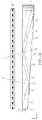
- FIG. 13Ais a schematic diagram illustrating in front view, an optical valve comprising a side light source arranged to achieve an on-axis optical window, in accordance with the present disclosure
- FIG. 13Bis a schematic diagram illustrating in side view, an optical valve comprising a side light source arranged to achieve an on-axis optical window, in accordance with the present disclosure
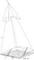
- FIG. 13Cis a schematic diagram illustrating in perspective view, the formation of first and second optical windows by edge and side light sources with a valve with arrangement similar to that shown in FIGS. 13A-13B , in accordance with the present disclosure;
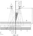
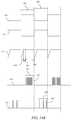
- FIGS. 14A-14Care schematic diagrams illustrating in top view, arrangements of viewing windows for a directional display in privacy mode for first and second phases of operation, in accordance with the present disclosure
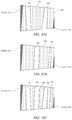
- FIGS. 15A-15Eare schematic diagrams illustrating the operation of a directional display in privacy mode wherein a primary image is provided on the spatial light modulator in at least one phase of operation, in accordance with the present disclosure
- FIGS. 16A-16Eare schematic diagrams illustrating the operation in a second phase of a directional display in privacy mode wherein a primary image is provided on the spatial light modulator in a first phase and a secondary image is provided on the spatial light modulator in a second phase, in accordance with the present disclosure;
- FIG. 16Fis a schematic graph illustrating the relationship between the grey levels of primary and second images, in accordance with the present disclosure.
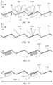
- FIG. 17is a schematic diagram illustrating sequence of image and illumination presentation to the spatial light modulator and light source array, in accordance with the present disclosure
- FIGS. 18A-18Care schematic diagrams illustrating perspective front views of the perceived image appearance for a privacy display with first and second phases comprising respective primary and secondary images further comprising cross talk from the secondary image to the primary observer, in accordance with the present disclosure
- FIG. 19Ais a schematic diagram illustrating a graph of display luminance and cross talk for the arrangement of FIGS. 17A-17C , in accordance with the present disclosure
- FIG. 19Bis a schematic diagram illustrating a graph of display luminance and cross talk for a stereoscopic privacy display, in accordance with the present disclosure
- FIG. 19Cis a schematic diagram illustrating sequence of image and illumination presentation to the spatial light modulator and light source array for a stereoscopic privacy display, in accordance with the present disclosure
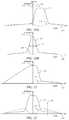
- FIGS. 20A-20B, 21, and 22are schematic diagrams illustrating graphs of angular luminance distributions for first and second phases, in accordance with the present disclosure
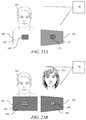
- FIGS. 23A-23Bare schematic diagrams illustrating perspective front views of the perceived image appearance for a privacy display in the second phase for non-detection and detection of a secondary observer respectively, in accordance with the present disclosure
- FIGS. 24-25are schematic diagrams illustrating graphs for first and second addressing schemes respectively of the variation of a pixel intensity level with time, the variation of addressing signal with time, and the variation of integrated luminance with time, in accordance with the present disclosure
- FIGS. 26A-26Bare schematic diagrams illustrating graphs of first and second addressing schemes respectively of the variation of an addressing signal with time, in accordance with the present disclosure
- FIGS. 27-28are schematic diagrams illustrating iso-contrast plots for twisted nematic and compensated twisted nematic liquid crystal displays respectively, in accordance with the present disclosure
- FIG. 29is a flow chart illustrating secondary image greyscale correction according to the measured polar position of a secondary observer, in accordance with the present disclosure
- FIG. 30is a schematic diagram illustrating a graph of first and second input greyscales against output transmission for a spatial light modulator, in accordance with the present disclosure
- FIG. 31is a flowchart illustrating the processing of signal data to achieve correct addressing of pixel data for alternating primary and secondary images, in accordance with the present disclosure
- FIGS. 32A-32Care schematic diagrams illustrating perspective front views of the image appearance for a privacy display with first and second phases comprising respective primary and secondary images, further comprising disruptive pattern image content, in accordance with the present disclosure
- FIG. 33is a flowchart illustrating the processing of signal data to achieve correct addressing of pixel data for alternating primary and secondary images comprising disruptive pattern image content, in accordance with the present disclosure
- FIGS. 34A-34Bare schematic timing diagrams illustrating the addressing of primary and secondary images and respective illumination signals, with matched phase length, in accordance with the present disclosure
- FIG. 34Cis a schematic timing diagram illustrating the addressing of primary and secondary images and respective illumination signals, with unmatched phase length, in accordance with the present disclosure
- FIGS. 35A-35Bare schematic diagrams illustrating the variation of spatial luminance across an optical valve for illumination by small numbers of light sources, in accordance with the present disclosure
- FIG. 35Cis a schematic diagram illustrating the combined spatial luminance across an optical valve for illumination by an increased numbers of light sources, in accordance with the present disclosure
- FIG. 36Ais a schematic diagram illustrating the cycling of image content in a privacy display, in accordance with the present disclosure
- FIG. 36Bis a schematic diagram illustrating the cycling of light source distribution in a privacy display, in accordance with the present disclosure
- FIGS. 36C-36Dare schematic diagrams illustrating the off-axis image appearance of images in first and second phases the luminance distribution across the image for first and second phases, in accordance with the present disclosure
- FIG. 36Eis a schematic flowchart illustrating the control of the arrangement of FIGS. 56-60 , in accordance with the present disclosure
- FIG. 37is a schematic diagram illustrating in front view the generation of stray light in an optical valve, in accordance with the present disclosure
- FIGS. 38A-38Care schematic graphs illustrating the angular distribution of output luminance for a display similar to the arrangement of FIG. 37 , in accordance with the present disclosure
- FIGS. 39-40are schematic diagrams illustrating in front views the formation and correction of image voids in an optical valve similar to the arrangement of FIG. 4A , in accordance with the present disclosure
- FIG. 41is a photo of the luminance distribution an optical valve for a privacy operation viewing position, in accordance with the present disclosure
- FIG. 42is a schematic diagram illustrating in a front view with a lateral angular offset isoluminance distribution regions for a privacy operation viewing position, in accordance with the present disclosure
- FIG. 43is a schematic graph illustrating greyscale mapping distributions for different display regions of FIG. 42 , in accordance with the present disclosure.
- FIGS. 44A-44Bare schematic graphs illustrating angular luminance variations for first and second display regions, in accordance with the present disclosure
- FIG. 45is a flowchart illustrating correction of mapping distributions for non-uniform greyscale mapping, in accordance with the present disclosure
- FIGS. 46-47are schematic diagrams illustrating in front view image correction regions, in accordance with the present disclosure.
- FIG. 48is a schematic diagram illustrating in perspective view an optical valve similar with masking layers arranged to reduce reflections from certain regions of the input side, in accordance with the present disclosure.
- FIGS. 49-52is a schematic diagram illustrating in front views the input side of an optical valve similar to that shown in FIG. 47 arranged to achieve reduced stray light in privacy viewing directions, in accordance with the present disclosure.
- Time multiplexed autostereoscopic displayscan advantageously improve the spatial resolution of an autostereoscopic display by directing light from all of the pixels of a spatial light modulator to a first viewing window in a first time slot, and all of the pixels to a second viewing window in a second time slot.
- Time multiplexed displayscan advantageously achieve directional illumination by directing an illuminator array through a substantially transparent time multiplexed spatial light modulator using directional optical elements, wherein the directional optical elements substantially form an image of the illuminator array in the window plane.
- the uniformity of the viewing windowsmay be advantageously independent of the arrangement of pixels in the spatial light modulator.
- Such displayscan provide observer tracking displays which have low flicker, with low levels of cross talk for a moving observer.
- the illuminator elements of the time sequential illumination systemmay be provided, for example, by pixels of a spatial light modulator with size approximately 100 micrometers in combination with a lens array.
- pixelssuffer from similar difficulties as for spatially multiplexed displays. Further, such devices may have low efficiency and higher cost, requiring additional display components.
- High window plane uniformitycan be conveniently achieved with macroscopic illuminators, for example, an array of LEDs in combination with homogenizing and diffusing optical elements that are typically of size 1 mm or greater.
- the increased size of the illuminator elementsmeans that the size of the directional optical elements increases proportionately. For example, a 16 mm wide illuminator imaged to a 65 mm wide viewing window may require a 200 mm back working distance.
- the increased thickness of the optical elementscan prevent useful application, for example, to mobile displays, or large area displays.
- optical valves as described in commonly-owned U.S. patent application Ser. No. 13/300,293advantageously can be arranged in combination with fast switching transmissive spatial light modulators to achieve time multiplexed autostereoscopic illumination in a thin package while providing high resolution images with flicker free observer tracking and low levels of cross talk.
- Describedis a one dimensional array of viewing positions, or windows, that can display different images in a first, typically horizontal, direction, but contain the same images when moving in a second, typically vertical, direction.
- imaging directional backlightsare arranged to direct the illumination from multiple light sources through a display panel to respective multiple viewing windows in at least one axis.
- Each viewing windowis substantially formed as an image in at least one axis of a light source by the imaging system of the imaging directional backlight.
- An imaging systemmay be formed between multiple light sources and the respective window images. In this manner, the light from each of the multiple light sources is substantially not visible for an observer's eye outside of the respective viewing window.
- Non-imaging backlightsare used for illumination of 2D displays. See, e.g., Kälil Käläntär et al., Backlight Unit With Double Surface Light Emission , J. Soc. Inf. Display, Vol. 12, Issue 4, pp. 379-387 (December 2004).
- Non-imaging backlightsare typically arranged to direct the illumination from multiple light sources through a display panel into a substantially common viewing zone for each of the multiple light sources to achieve wide viewing angle and high display uniformity.
- non-imaging backlightsdo not form viewing windows. In this manner, the light from each of the multiple light sources may be visible for an observer's eye at substantially all positions across the viewing zone.
- Such conventional non-imaging backlightsmay have some directionality, for example, to increase screen gain compared to Lambertian illumination, which may be provided by brightness enhancement films such as BEFTM from 3M. However, such directionality may be substantially the same for each of the respective light sources. Thus, for these reasons and others that should be apparent to persons of ordinary skill, conventional non-imaging backlights are different to imaging directional backlights.
- Edge lit non-imaging backlight illumination structuresmay be used in liquid crystal display systems such as those seen in 2D Laptops, Monitors and TVs. Light propagates from the edge of a lossy waveguide which may include sparse features; typically local indentations in the surface of the guide which cause light to be lost regardless of the propagation direction of the light.
- an optical valveis an optical structure that may be a type of light guiding structure or device referred to as, for example, a light valve, an optical valve directional backlight, and a valve directional backlight (“v-DBL”).
- optical valveis different to a spatial light modulator (even though spatial light modulators may be sometimes generally referred to as a “light valve” in the art).
- One example of an imaging directional backlightis an optical valve that may employ a folded optical system. Light may propagate substantially without loss in one direction through the optical valve, may be incident on an imaging reflector, and may counter-propagate such that the light may be extracted by reflection off tilted light extraction features, and directed to viewing windows as described in patent application Ser. No. 13/300,293, which is herein incorporated by reference in its entirety.
- an imaging directional backlightexamples include a stepped waveguide imaging directional backlight, a folded imaging directional backlight, or an optical valve.
- a stepped waveguide imaging directional backlightmay be an optical valve.
- a stepped waveguideis a waveguide for an imaging directional backlight including a waveguide for guiding light, further including a first light guiding surface; and a second light guiding surface, opposite the first light guiding surface, further including a plurality of light guiding features interspersed with a plurality of extraction features arranged as steps.
- lightmay propagate within an exemplary optical valve in a first direction from an input side to a reflective side and may be transmitted substantially without loss.
- Lightmay be reflected at the reflective side and propagates in a second direction substantially opposite the first direction.
- the lightmay be incident on light extraction features, which are operable to redirect the light outside the optical valve.
- the optical valvegenerally allows light to propagate in the first direction and may allow light to be extracted while propagating in the second direction.
- the optical valvemay achieve time sequential directional illumination of large display areas. Additionally, optical elements may be employed that are thinner than the back working distance of the optical elements to direct light from macroscopic illuminators to a window plane. Such displays may use an array of light extraction features arranged to extract light counter propagating in a substantially parallel waveguide.
- Thin imaging directional backlight implementations for use with LCDshave been proposed and demonstrated by 3M, for example U.S. Pat. No. 7,528,893; by Microsoft, for example U.S. Pat. No. 7,970,246 which may be referred to herein as a “wedge type directional backlight;” by RealD, for example U.S. patent application Ser. No. 13/300,293 which may be referred to herein as an “optical valve” or “optical valve directional backlight,” all of which are herein incorporated by reference in their entirety.
- the present disclosureprovides stepped waveguide imaging directional backlights in which light may reflect back and forth between the internal faces of, for example, a stepped waveguide which may include a first side and a first set of features. As the light travels along the length of the stepped waveguide, the light may not substantially change angle of incidence with respect to the first side and first set of surfaces and so may not reach the critical angle of the medium at these internal faces. Light extraction may be advantageously achieved by a second set of surfaces (the step “risers”) that are inclined to the first set of surfaces (the step “treads”). Note that the second set of surfaces may not be part of the light guiding operation of the stepped waveguide, but may be arranged to provide light extraction from the structure.
- a wedge type imaging directional backlightmay allow light to guide within a wedge profiled waveguide having continuous internal surfaces. The optical valve is thus not a wedge type imaging directional backlight.
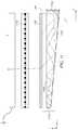
- FIG. 1Ais a schematic diagram illustrating a front view of light propagation in one embodiment of a directional display device
- FIG. 1Bis a schematic diagram illustrating a side view of light propagation in the directional display device of FIG. 1A .
- FIG. 1Aillustrates a front view in the xy plane of a directional backlight of a directional display device, and includes an illuminator array 15 which may be used to illuminate a stepped waveguide 1 .
- Illuminator array 15includes illuminator elements 15 a through illuminator element 15 n (where n is an integer greater than one).
- the stepped waveguide 1 of FIG. 1Amay be a stepped, display sized waveguide 1 .
- Illumination elements 15 a through 15 nare light sources that may be light emitting diodes (LEDs).
- FIG. 1Billustrates a side view in the xz plane, and includes illuminator array 15 , SLM (spatial light modulator) 48 , extraction features 12 , guiding features 10 , and stepped waveguide 1 , arranged as shown.
- the side view provided in FIG. 1Bis an alternative view of the front view shown in FIG. 1A . Accordingly, the illuminator array 15 of FIGS. 1A and 1B corresponds to one another and the stepped waveguide 1 of FIGS. 1A and 1B may correspond to one another.
- the stepped waveguide 1may have an input end 2 that is thin and a reflective end 4 that is thick.
- the waveguide 1extends between the input end 2 that receives input light and the reflective end 4 that reflects the input light back through the waveguide 1 .
- the length of the input end 2 in a lateral direction across the waveguideis greater than the height of the input end 2 .
- the illuminator elements 15 a - 15 nare disposed at different input positions in a lateral direction across the input end 2 .
- the waveguide 1has first and second, opposed guide surfaces extending between the input end 2 and the reflective end 4 for guiding light forwards and back along the waveguide 1 by total internal reflection.
- the first guide surfaceis planar.
- the second guide surfacehas a plurality of light extraction features 12 facing the reflective end 4 and inclined to reflect at least some of the light guided back through the waveguide 1 from the reflective end in directions that break the total internal reflection at the first guide surface and allow output through the first guide surface, for example, upwards in FIG. 1B , that is supplied to the SLM 48 .
- the light extraction features 12are reflective facets, although other reflective features may be used.
- the light extraction features 12do not guide light through the waveguide, whereas the intermediate regions of the second guide surface intermediate the light extraction features 12 guide light without extracting it. Those regions of the second guide surface are planar and may extend parallel to the first guide surface, or at a relatively low inclination.
- the light extraction features 12extend laterally to those regions so that the second guide surface has a stepped shape including of the light extraction features 12 and intermediate regions.
- the light extraction features 12are oriented to reflect light from the light sources, after reflection from the reflective end 4 , through the first guide surface.
- the light extraction features 12are arranged to direct input light from different input positions in the lateral direction across the input end in different directions relative to the first guide surface that are dependent on the input position.
- the illumination elements 15 a - 15 nare arranged at different input positions, the light from respective illumination elements 15 a - 15 n is reflected in those different directions.
- each of the illumination elements 15 a - 15 ndirects light into a respective optical window in output directions distributed in the lateral direction in dependence on the input positions.
- the lateral direction across the input end 2 in which the input positions are distributedcorresponds with regard to the output light to a lateral direction to the normal to the first guide surface.
- the illuminator elements 15 a - 15 nmay be selectively operated to direct light into a selectable optical window.
- the optical windowsmay be used individually or in groups as viewing windows.
- the reflective end 4may have positive optical power in the lateral direction across the waveguide.
- the optical axismay be defined with reference to the shape of the reflective end 4 , for example being a line that passes through the center of curvature of the reflective end 4 and coincides with the axis of reflective symmetry of the end 4 about the x-axis.
- the optical axismay be similarly defined with respect to other components having optical power, for example the light extraction features 12 if they are curved, or the Fresnel lens 62 described below.
- the optical axis 238is typically coincident with the mechanical axis of the waveguide 1 .
- the SLM 48extends across the waveguide is transmissive and modulates the light passing therethrough.
- the SLM 48may be a liquid crystal display (LCD) but this is merely by way of example, and other spatial light modulators or displays may be used including LCOS, DLP devices, and so forth, as this illuminator may work in reflection.
- the SLM 48is disposed across the first guide surface of the waveguide and modulates the light output through the first guide surface after reflection from the light extraction features 12 .
- FIG. 1AThe operation of a directional display device that may provide a one dimensional array of viewing windows is illustrated in front view in FIG. 1A , with its side profile shown in FIG. 1B .
- the lightmay propagate along +x in a first direction, within the stepped waveguide 1 , while at the same time, the light may fan out in the xy plane and upon reaching the far curved end side 4 , may substantially or entirely fill the curved end side 4 . While propagating, the light may spread out to a set of angles in the xz plane up to, but not exceeding the critical angle of the guide material.
- the extraction features 12 that link the guiding features 10 of the bottom side of the stepped waveguide 1may have a tilt angle greater than the critical angle and hence may be missed by substantially all light propagating along +x in the first direction, ensuring the substantially lossless forward propagation.
- the curved end side 4 of the stepped waveguide 1may be made reflective, typically by being coated with a reflective material such as, for example, silver, although other reflective techniques may be employed.
- Lightmay therefore be redirected in a second direction, back down the guide in the direction of ⁇ x and may be substantially collimated in the xy or display plane.
- the angular spreadmay be substantially preserved in the xz plane about the principal propagation direction, which may allow light to hit the riser edges and reflect out of the guide.
- lightmay be effectively directed approximately normal to the xy display plane with the xz angular spread substantially maintained relative to the propagation direction. This angular spread may be increased when light exits the stepped waveguide 1 through refraction, but may be decreased somewhat dependent on the reflective properties of the extraction features 12 .
- reflectionmay be reduced when total internal reflection (TIR) fails, squeezing the xz angular profile and shifting off normal.
- TIRtotal internal reflection
- the increased angular spread and central normal directionmay be preserved.
- lightmay exit the stepped waveguide 1 approximately collimated and may be directed off normal in proportion to the y-position of the respective illuminator element 15 a - 15 n in illuminator array 15 from the input edge center. Having independent illuminator elements 15 a - 15 n along the input edge 2 then enables light to exit from the entire first light directing side 6 and propagate at different external angles, as illustrated in FIG. 1A .
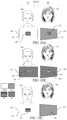
- Illuminating a spatial light modulator (SLM) 48 such as a fast liquid crystal display (LCD) panel with such a devicemay achieve autostereoscopic 3D as shown in top view or yz-plane viewed from the illuminator array 15 end in FIG. 2A , front view in FIG. 2B and side view in FIG. 2C .
- FIG. 2Ais a schematic diagram illustrating in a top view, propagation of light in a directional display device
- FIG. 2Bis a schematic diagram illustrating in a front view, propagation of light in a directional display device
- FIG. 2Cis a schematic diagram illustrating in side view propagation of light in a directional display device.
- FIGS. 1spatial light modulator
- a stepped waveguide 1may be located behind a fast (e.g., greater than 100 Hz) LCD panel SLM 48 that displays sequential right and left eye images.
- a faste.g., greater than 100 Hz
- specific illuminator elements 15 a through 15 n of illuminator array 15may be selectively turned on and off, providing illuminating light that enters right and left eyes substantially independently by virtue of the system's directionality.
- sets of illuminator elements of illuminator array 15are turned on together, providing a one dimensional viewing window 26 or an optical pupil with limited width in the horizontal direction, but extended in the vertical direction, in which both eyes horizontally separated may view a left eye image, and another viewing window 44 in which a right eye image may primarily be viewed by both eyes, and a central position in which both the eyes may view different images.
- 3Dmay be viewed when the head of a viewer is approximately centrally aligned. Movement to the side away from the central position may result in the scene collapsing onto a 2D image.
- the reflective end 4may have positive optical power in the lateral direction across the waveguide.
- the optical axismay be defined with reference to the shape of the reflective end 4 , for example being a line that passes through the center of curvature of the reflective end 4 and coincides with the axis of reflective symmetry of the end 4 about the x-axis.
- the optical axismay be similarly defined with respect to other components having optical power, for example the light extraction features 12 if they are curved, or the Fresnel lens 62 described below.
- the optical axis 238is typically coincident with the mechanical axis of the waveguide 1 .
- the cylindrical reflecting surface at end 4may typically be a spherical profile to optimize performance for on-axis and off-axis viewing positions. Other profiles may be used.
- FIG. 3is a schematic diagram illustrating in side view a directional display device. Further, FIG. 3 illustrates additional detail of a side view of the operation of a stepped waveguide 1 , which may be a transparent material.
- the stepped waveguide 1may include an illuminator input side 2 , a reflective side 4 , a first light directing side 6 which may be substantially planar, and a second light directing side 8 which includes guiding features 10 and light extraction features 12 .
- light rays 16 from an illuminator element 15 c of an illuminator array 15(not shown in FIG.
- reflective side 4may be a mirrored surface and may reflect light, it may in some embodiments also be possible for light to pass through reflective side 4 .
- light ray 18 reflected by the reflective side 4may be further guided in the stepped waveguide 1 by total internal reflection at the reflective side 4 and may be reflected by extraction features 12 .
- Light rays 18 that are incident on extraction features 12may be substantially deflected away from guiding modes of the stepped waveguide 1 and may be directed, as shown by ray 20 , through the side 6 to an optical pupil that may form a viewing window 26 of an autostereoscopic display.
- the width of the viewing window 26may be determined by at least the size of the illuminator, output design distance and optical power in the side 4 and extraction features 12 .
- each viewing window 26represents a range of separate output directions with respect to the surface normal direction of the spatial light modulator 48 that intersect with a plane at the nominal viewing distance.
- FIG. 4Ais a schematic diagram illustrating in front view a directional display device which may be illuminated by a first illuminator element and including curved light extraction features. Further, FIG. 4A shows in front view further guiding of light rays from illuminator element 15 c of illuminator array 15 , in the stepped waveguide 1 having an optical axis 28 .
- the directional backlightmay include the stepped waveguide 1 and the light source illuminator array 15 .
- Each of the output raysare directed from the input side 2 towards the same viewing window 26 from the respective illuminator 15 c .
- the light rays of FIG. 4Amay exit the reflective side 4 of the stepped waveguide 1 .
- ray 16may be directed from the illuminator element 15 c towards the reflective side 4 .
- Ray 18may then reflect from a light extraction feature 12 and exit the reflective side 4 towards the viewing window 26 .
- light ray 30may intersect the ray 20 in the viewing window 26 , or may have a different height in the viewing window as shown by ray 32 .
- sides 22 , 24 of the waveguide 1may be transparent, mirrored, or blackened surfaces.
- light extraction features 12may be elongate, and the orientation of light extraction features 12 in a first region 34 of the light directing side 8 (light directing side 8 shown in FIG. 3 , but not shown in FIG.
- the stepped waveguide 1may include a reflective surface on reflective side 4 .
- the reflective end of the stepped waveguide 1may have positive optical power in a lateral direction across the stepped waveguide 1 .
- the light extraction features 12 of each directional backlightmay have positive optical power in a lateral direction across the waveguide.
- each directional backlightmay include light extraction features 12 which may be facets of the second guide surface.
- the second guide surfacemay have regions alternating with the facets that may be arranged to direct light through the waveguide without substantially extracting it.
- FIG. 4Bis a schematic diagram illustrating in front view a directional display device which may illuminated by a second illuminator element. Further, FIG. 4B shows the light rays 40 , 42 from a second illuminator element 15 h of the illuminator array 15 . The curvature of the reflective surface on the side 4 and the light extraction features 12 cooperatively produce a second viewing window 44 laterally separated from the viewing window 26 with light rays from the illuminator element 15 h.
- the arrangement illustrated in FIG. 4Bmay provide a real image of the illuminator element 15 c at a viewing window 26 in which the real image may be formed by cooperation of optical power in reflective side 4 and optical power which may arise from different orientations of elongate light extraction features 12 between regions 34 and 36 , as shown in FIG. 4A .
- the arrangement of FIG. 4Bmay achieve improved aberrations of the imaging of illuminator element 15 c to lateral positions in viewing window 26 . Improved aberrations may achieve an extended viewing freedom for an autostereoscopic display while achieving low cross talk levels.
- FIG. 5is a schematic diagram illustrating in front view an embodiment of a directional display device having substantially linear light extraction features. Further, FIG. 5 shows a similar arrangement of components to FIG. 1 (with corresponding elements being similar), with one of the differences being that the light extraction features 12 are substantially linear and parallel to each other. Advantageously, such an arrangement may provide substantially uniform illumination across a display surface and may be more convenient to manufacture than the curved extraction features of FIG. 4A and FIG. 4B .
- the optical axis 321 of the directional waveguide 1may be the optical axis direction of the surface at side 4 .
- the optical power of the side 4is arranged to be across the optical axis direction, thus rays incident on the side 4 will have an angular deflection that varies according to the lateral offset 319 of the incident ray from the optical axis 321 .
- FIG. 6Ais a schematic diagram illustrating one embodiment of the generation of a first viewing window in a time multiplexed imaging directional display device in a first time slot
- FIG. 6Bis a schematic diagram illustrating another embodiment of the generation of a second viewing window in a time multiplexed imaging directional backlight apparatus in a second time slot
- FIG. 6Cis a schematic diagram illustrating another embodiment of the generation of a first and a second viewing window in a time multiplexed imaging directional display device.
- FIG. 6Ashows schematically the generation of viewing window 26 from stepped waveguide 1 .
- Illuminator element group 31 in illuminator array 15may provide a light cone 17 directed towards a viewing window 26 .
- Illuminator element group 33 in illuminator array 15may provide a light cone 19 directed towards viewing window 44 .
- windows 26 and 44may be provided in sequence as shown in FIG. 6C . If the image on a spatial light modulator 48 (not shown in FIGS. 6A, 6B, 6C ) is adjusted in correspondence with the light direction output, then an autostereoscopic image may be achieved for a suitably placed viewer. Similar operation can be achieved with all the imaging directional backlights described herein.
- illuminator element groups 31 , 33each include one or more illumination elements from illumination elements 15 a to 15 n , where n is an integer greater than one.
- FIG. 7is a schematic diagram illustrating one embodiment of an observer tracking autostereoscopic display apparatus including a time multiplexed directional display device.
- selectively turning on and off illuminator elements 15 a to 15 n along axis 29provides for directional control of viewing windows.
- the head 45 positionmay be monitored with a camera, motion sensor, motion detector, or any other appropriate optical, mechanical or electrical means, and the appropriate illuminator elements of illuminator array 15 may be turned on and off to provide substantially independent images to each eye irrespective of the head 45 position.
- the head tracking system(or a second head tracking system) may provide monitoring of more than one head 45 , 47 (head 47 not shown in FIG. 7 ) and may supply the same left and right eye images to each viewers' left and right eyes providing 3D to all viewers. Again similar operation can be achieved with all the imaging directional backlights described herein.
- FIG. 8is a schematic diagram illustrating one embodiment of a multi-viewer directional display device as an example including an imaging directional backlight.
- at least two 2D imagesmay be directed towards a pair of viewers 45 , 47 so that each viewer may watch a different image on the spatial light modulator 48 .
- the two 2D images of FIG. 8may be generated in a similar manner as described with respect to FIG. 7 in that the two images may be displayed in sequence and in synchronization with sources whose light is directed toward the two viewers.
- One imageis presented on the spatial light modulator 48 in a first phase
- a second imageis presented on the spatial light modulator 48 in a second phase different from the first phase.
- the output illuminationis adjusted to provide first and second viewing windows 26 , 44 respectively. An observer with both eyes in viewing window 26 will perceive a first image while an observer with both eyes in viewing window 44 will perceive a second image.
- FIG. 9is a schematic diagram illustrating a privacy directional display device which includes an imaging directional backlight.
- 2D display systemsmay also utilize directional backlighting for security and efficiency purposes in which light may be primarily directed at the eyes of a first viewer 45 as shown in FIG. 9 .
- first viewer 45may be able to view an image on device 50
- lightis not directed towards second viewer 47 .
- second viewer 47is prevented from viewing an image on device 50 .
- Each of the embodiments of the present disclosuremay advantageously provide autostereoscopic, dual image or privacy display functions.
- FIG. 10is a schematic diagram illustrating in side view the structure of a time multiplexed directional display device as an example including an imaging directional backlight. Further, FIG. 10 shows in side view an autostereoscopic directional display device, which may include the stepped waveguide 1 and a Fresnel lens 62 arranged to provide the viewing window 26 for a substantially collimated output across the stepped waveguide 1 output surface. A vertical diffuser 68 may be arranged to extend the height of the viewing window 26 further. The light may then be imaged through the spatial light modulator 48 .
- the illuminator array 15may include light emitting diodes (LEDs) that may, for example, be phosphor converted blue LEDs, or may be separate RGB LEDs.
- LEDslight emitting diodes
- the illuminator elements in illuminator array 15may include a uniform light source and spatial light modulator arranged to provide separate illumination regions.
- the illuminator elementsmay include laser light source(s).
- the laser outputmay be directed onto a diffuser by means of scanning, for example, using a galvo or MEMS scanner.
- laser lightmay thus be used to provide the appropriate illuminator elements in illuminator array 15 to provide a substantially uniform light source with the appropriate output angle, and further to provide reduction in speckle.
- the illuminator array 15may be an array of laser light emitting elements.
- the diffusermay be a wavelength converting phosphor, so that illumination may be at a different wavelength to the visible output light.
- waveguides, directional backlights and directional display devicesthat are based on and incorporate the structures of FIGS. 1 to 10 above. Except for the modifications and/or additional features which will now be described, the above description applies equally to the following waveguides, directional backlights and display devices, but for brevity will not be repeated.
- the waveguides described belowmay be incorporated into a directional backlight or a directional display device as described above.
- the directional backlights described belowmay be incorporated into a directional display device as described above.
- Optical windows from a directional backlightmay be formed by one light source of the array 15 of light sources.
- Optical windows from a parallax element and spatial light modulatormay be formed by a first set of pixel columns, each with one respective aligned slit of the parallax element.
- Viewing windowsmay comprise multiple optical windows.
- FIG. 11is a schematic diagram illustrating in side view, the structure of a directional display device comprising a wedge waveguide 1104 with faceted mirror end 1102 .
- the first guide surface 1105 of the waveguide 1104is arranged to guide light by total internal reflection and the second guide surface 1106 is substantially planar and inclined at an angle to direct light in directions that break the total internal reflection for outputting light through the first guide surface 1105 .
- the display devicefurther comprises a deflection element 1108 extending across the first guide surface 1105 of the waveguide 1104 for deflecting light from array 1101 of light sources towards the normal to the first guide surface 1105 .
- the waveguide 1104may further comprise a reflective end 1102 for reflecting input light back through the waveguide 1104 , the second guide 1106 surface being arranged to deflect light as output light through the first guide surface 1105 after reflection from the reflective end 1102 .
- the reflective endhas positive optical power in the lateral direction (y-axis) in a similar manner to the reflective end shown in FIG. 5 for example. Further facets in the reflective end 1102 deflect the reflected light cones within the waveguide 1104 to achieve output coupling on the return path. Thus viewing windows are produced in a similar manner to that shown in FIG. 11A .
- the directional displaymay comprise a spatial light modulator 1110 and parallax element 1100 aligned to the spatial light modulator 1110 that is further arranged to provide optical windows.
- a control system 72 similar to that shown in FIG. 11Amay be arranged to provide control of directional illumination providing viewing windows 26 and windows 109 from the parallax element and aligned spatial light modulator.
- a first guide surfacemay be arranged to guide light by total internal reflection and the second guide surface may be substantially planar and inclined at an angle to direct light in directions that break that total internal reflection for outputting light through the first guide surface, and the display device may further comprise a deflection element extending across the first guide surface of the waveguide for deflecting light towards the normal to the first guide surface.
- FIG. 12Ais a schematic diagram illustrating a directional display apparatus comprising a display device 100 and a control system.
- the arrangement and operation of the control systemwill now be described and may be applied, changing that which may be appropriately changed, to each of the display devices disclosed herein.
- a directional display device 100may include a directional backlight device that may itself include a stepped waveguide 1 and a light source illuminator array 15 .
- the stepped waveguide 1includes a light directing side 8 , a reflective end 4 , guiding features 10 and light extraction features 12 .
- the directional display device 100may further include an SLM 48 .
- the waveguide 1is arranged as described above.
- the reflective end 4converges the reflected light.
- a Fresnel lens 62may be arranged to cooperate with reflective end 4 to achieve viewing windows 26 at a viewing plane 106 observed by an observer 99 .
- a transmissive SLM 48may be arranged to receive the light from the directional backlight.
- a diffuser 68may be provided to substantially remove Moiré beating between the waveguide 1 and pixels of the SLM 48 as well as the Fresnel lens structure 62 .
- Diffuser 68may be an asymmetric diffuser arranged to provide diffusion in the vertical direction (x-axis) that is greater than the diffusion in the lateral direction (y-axis).
- the display uniformitycan be increased and the cross talk between adjacent viewing windows minimized
- the control systemmay comprise a sensor system arranged to detect the position of the observer 99 relative to the display device 100 .
- the sensor systemcomprises a position sensor 70 , such as a camera, and a head position measurement system 72 that may for example comprise a computer vision image processing system.
- the control systemmay further comprise an illumination controller 74 and an image controller 76 that are both supplied with the detected position of the observer supplied from the head position measurement system 72 .
- the illumination controller 74selectively operates the illuminator elements 15 to direct light to into the viewing windows 26 in cooperation with waveguide 1 .
- the illumination controller 74selects the illuminator elements 15 to be operated in dependence on the position of the observer detected by the head position measurement system 72 , so that the viewing windows 26 into which light is directed are in positions corresponding to the left and right eyes of the observer 99 . In this manner, the lateral output directionality of the waveguide 1 corresponds with the observer position.
- the image controller 76controls the SLM 48 to display images.
- the image controller 76 and the illumination controller 74may operate as follows.
- the image controller 76controls the SLM 48 to display temporally multiplexed left and right eye images.
- the illumination controller 74operate the light sources 15 to direct light into respective viewing windows in positions corresponding to the left and right eyes of an observer synchronously with the display of left and right eye images.
- an autostereoscopic effectmay be achieved using a time division multiplexing technique.
- a low contrast privacy effectmay be achieved using a time division multiplexing technique as will be described herein.
- FIG. 12Bis a schematic diagram illustrating in perspective view, the structure of a directional display device comprising a waveguide 1 arranged with a spatial light modulator 48 .
- Reflective end 4may be provided by a Fresnel mirror.
- Taper region 204may be arranged at the input to the waveguide 1 to increase input coupling efficiency from the light sources 15 a - 15 n of the array of illuminator elements 15 and to increase illumination uniformity.
- Shading layer 206 with aperture 203may be arranged to hide light scattering regions at the edge of the waveguide 1 .
- Rear reflector 200may comprise facets 202 that are curved and arranged to provide viewing windows 26 from groups of optical windows provided by imaging light sources of the array 15 to the window plane 106 .
- Optical stack 208may comprise reflective polarizers, retarder layers and diffusers.
- Rear reflectors 200 and optical stack 208are described further in U.S. patent application Ser. No. 14/186,862, filed Feb. 21, 2014, entitled “Directional backlight” incorporated herein by reference in its entirety.
- Spatial light modulator 48may comprise a liquid crystal display that may comprise an input polarizer 210 , TFT glass substrate 212 , liquid crystal layer 214 , color filter glass substrate 216 and output polarizer 218 .
- Red pixels 220 , green pixels 222 and blue pixels 224may be arranged in an array at the liquid crystal layer 214 .
- White, yellow, additional green or other color pixelsmay be further arranged in the liquid crystal layer to increase transmission efficiency, color gamut or perceived image resolution.
- FIG. 12Cis a schematic diagram illustrating in perspective view, the formation of an optical window by edge and side light sources with a valve with arrangement similar to that shown in FIG. 4A .
- Light ray 230 from source 15 n that is offset from optical axis 199is reflected at reflective end 4 and directed to an off-axis optical window 26 , that is offset in a lateral direction from axis 197 in the window plane.
- light ray 232 from source 17 n on side 22may be directed to optical window 26 by means of total internal reflection at side 24 .
- directional display apparatus 100comprises a directional backlight comprising a waveguide 1 comprising first and second, opposed guide surfaces 6 , 8 for guiding input light along the waveguide 1 , and an array 15 of light sources 15 a - n arranged to generate the input light at different input positions in a lateral direction across the waveguide 1 .
- the first guide surface 6may be arranged to guide light by total internal reflection
- second guide surface 8comprises a plurality of light extraction features 12 arranged to deflect light guided through the waveguide 1 out of the waveguide 1 through the first guide surface 8 as output light and intermediate regions 10 between the light extraction features 12 that are arranged to guide light along the waveguide 1
- the waveguide 1is arranged to direct the output light into optical windows 26 in output directions that are distributed in a lateral direction in dependence on the input position of the input light.
- a transmissive spatial light modulator 48is arranged to receive the output light from the first guide surface 6 of the waveguide and to modulate it to display an image.
- Such displaysmay be arranged to provide high efficiency by directing light to viewing windows near an observer and not wasting light in directions that are not in the region of the observer's eyes. Further such displays can desirably provide high luminance for improved visibility in environments with high ambient illuminance.
- the spatial light modulatormay be a temporally multiplexed spatial modulator with a frame rate of 120 Hz for example, achieving images comprising primary and secondary images with a 60 Hz frame rate.
- Such a directional display devicemay achieve autostereoscopic display through temporal multiplexing as described above.
- the first guide surfacemay be arranged to guide light by total internal reflection and the second guide surface may comprise a plurality of light extraction features oriented to direct light guided through the waveguide in directions allowing exit through the first guide surface as the output light and intermediate regions between the light extraction features that are arranged to guide light through the waveguide.
- the second guide surfacemay have a stepped shape comprising facets, that are said light extraction features, and the intermediate regions.
- the directional backlightmay further comprise a rear reflector comprising a linear array of reflective facets arranged to reflect light from the light sources that is transmitted through the plurality of facets of the waveguide, back through the waveguide to exit through the first guide surface into said optical windows.
- the light extraction featuresmay have positive optical power in the lateral direction.
- the waveguidemay further comprise an input end, the array of light sources being arranged along the input end.
- the waveguidemay further comprise a reflective end for reflecting input light back through the waveguide, the second guide surface being arranged to deflect light as output light through the first guide surface after reflection from the reflective end.
- the reflective endmay have positive optical power in the lateral direction.
- FIGS. 13A-13Care schematic diagrams illustrating in front, side and perspective views respectively, an optical valve comprising a light source 317 a arranged to achieve an on-axis optical window.
- a directional display devicemay comprise a waveguide 1301 that further comprises a reflective end 1304 that is elongated in a lateral direction (y-axis), the first and second guide surfaces 6 , 8 extending from laterally extending edges of the reflective end 1304 , the waveguide 1301 further comprising side surfaces 1322 , 1324 extending between the first and second guide surfaces 6 , 8 , and wherein the light sources include an array 1317 of light sources 1317 a - n arranged along a side surface 1322 to provide said input light through that side surface 1322 , and the reflective end 1304 , comprises first and second facets 1327 , 1329 alternating with each other in the lateral direction, the first facets 1327 being reflective and forming reflective facets of a Fresnel reflector having positive optical power in the
- the second facets 1329may be reflective and form reflective facets of a Fresnel reflector having positive optical power in the lateral direction, the Fresnel reflector 1304 having an optical axis 1289 that is inclined towards the side surface 1324 in a direction in which the Fresnel reflector 1304 deflects input light from the array of light sources 1319 into the waveguide 1301 .
- Illustrative light ray 1363 from source 1317 amay be arranged to provide optical window 1326 a and light ray 1365 from source 1317 b may be arranged to provide optical window 1326 b .
- Other layerssuch as diffusers, prismatic reflection films, retarders and spatial light modulators may be arranged in series with the waveguide 1301 in a similar manner to that described for waveguide 1 in the arrangement of FIG. 12B for example.
- a thin backlight with low bezel sizemay be achieved.
- Such an arrangementhas light sources that are not arranged on the long sides of the waveguide 1301 and thus may have small form factor. Further light sources 1317 and 1319 may be arranged with overlapping optical windows, and thus display luminance may be increased.
- FIG. 14Ais a schematic diagram illustrating in top view, the arrangement of viewing windows for a directional display in privacy mode, similar to that shown in FIG. 9 , however a single two dimensional image is provided in viewing cone 249 and formed by illumination of optical windows 26 in the window plane 106 .
- viewing window 247is formed from a combination of optical windows 26 from the display 100 .
- illumination of optical windows 26 in the window plane 106is provided by stray light in the directional backlight system.
- Such directional lightmay for example be provided by scatter, aberrations and reflection of light from the input facet 2 of the waveguide 1 .
- the stray light luminance of the display 100 when observed from within the viewing window 245may be finite, for example between 1% and 20% of the peak luminance of the viewing window 247 .
- an optical windowis formed by a single light source of the array 15 of light sources 15 a - n .
- a viewing windowis formed by a combination of optical windows.
- a control system 70 , 72 , 74 , 76 shown in FIG. 12Ais capable of controlling the spatial light modulator 48 and capable of selectively operating of light sources 15 a - n to direct light into corresponding optical windows 26 , wherein stray light in the directional backlight is directed in output directions, illustrated by cones 233 , 245 , outside the optical windows 26 corresponding to selectively operated light sources.
- FIG. 14Ashows the operation of a privacy display comprising off-axis luminance control as will be described with reference to FIGS. 15A-15E .
- FIG. 14Ashows the operation of a privacy display in a first phase of operation comprising off-axis luminance and contrast control as will be described with reference to FIGS. 16A-16E .
- FIG. 14Bis a schematic diagram illustrating in top view, the arrangement of optical windows for a directional display in the second phase of operation of a privacy mode of the present embodiments.
- secondary viewing windows 241 , 243 shown with secondary viewing cones 252 , 254 for a single point on the displayare provided to either side of the viewing windows 247 .
- FIG. 14Cis a schematic diagram illustrating in top view, the arrangement of optical windows for a directional display in the first and second phases of operation of a privacy mode of the present embodiments. Between the viewing cones 250 and 252 , 254 transition cones 256 , 258 are provided from which the display luminance will appear to change between the primary and secondary cones.
- the primary observermay be arranged within the primary viewing cone 250 and secondary observers may be arranged within secondary viewing cones 254 .
- the position of a primary observermay be within the primary optical window that may be a primary viewing window provided by multiple optical windows 26 .
- the secondary observermay be outside the primary optical window and may be within a secondary optical window that may be a secondary viewing window provided by multiple optical windows 26 .
- the primary optical window(which may a primary viewing window comprising multiple optical windows) may be defined as the width of the luminance distribution at which the intensity drops to less than 50% of the peak luminance.
- the stray lightmay provide a relatively uniform luminance distribution, due to the substantially uniform distribution of light across the input side 2 that is reflected.
- FIGS. 14A-Cas well as wide angle modes, high efficiency modes, high luminance modes and autostereoscopic modes may be switchable by means of control of the array 15 of light sources.
- FIGS. 15A-15Eare schematic diagrams illustrating the operation of a directional display in privacy mode wherein a primary image is provided on the spatial light modulator in at least one phase of operation. Such arrangements may be used for example in cooperation with a viewing window arrangement such as shown in FIG. 14A for a low luminance privacy display, or as shown in FIG. 14B for an obscured image privacy display as described herein.
- FIG. 15Ashows the relative luminous flux 262 of the light sources 15 a - n in array 15 of light sources against position 260 to achieve primary illumination structure in the window plane. Accordingly this is an example in which there are plural primary light sources.
- individual light source flux 264may be uniform in a region near the center of the array, and zero in other regions. Alternatively the flux 264 may vary across the illuminated elements to provide a graded luminance with viewing angle within the primary viewing cone 250 .
- FIG. 15Bshows an example displayed primary image 261 on the spatial light modulator 48 that comprises a low transmittance region 268 , for example 0% transmittance and high transmittance region 266 , for example 100%.
- FIG. 15Cshows a graph that illustrates the variation of relative luminance and contrast with viewing angle 270 of the display 100 .
- luminance distribution 272comprises a central viewing window 247 and stray light region 241 wherein the luminance is non-zero, for example 10% at the angular position 251 in the following illustrative example.
- the amount of stray lightmay vary within the region 241 , as shown. However, as stray light may be determined mainly be return reflections from the input side 2 of the waveguide 1 , relatively uniform output may be achieved in these regions.
- the primary viewing windowmay have an edge width 256 .
- FIG. 15Cfurther illustrates a distribution 274 of contrast of the perceived image seen on the spatial light modulator 48 with viewing angle.
- contrastmay be substantially uniform on-axis but may fall for off axis positions as will be described further for FIGS. 27-28 below.
- FIG. 15Dillustrates the perceived primary image 280 for a primary observer in the primary viewing window 247 , such that regions 267 , 269 have relative luminances of 100%, 0% that are substantially equivalent to relative transmittances of regions 266 , 268 respectively.
- FIG. 15Eshows, using a representation of perspective, the perceived secondary image 282 for angular position 251 comprising regions 271 , 273 .
- Region 273may have substantially 0% luminance
- region 271may have 10% luminance in this illustrative example, being the transmittance of region 266 modulated by the stray light luminance at angular position 251 .
- FIGS. 15A-15Emay provide a privacy mode operation in which the luminance for a secondary observer is 10% of the luminance for the primary observer.
- Such an image luminancemay provide obscuration of the primary image to the secondary observer.
- obscurationmay be provided by (i) frontal reflections and (ii) adaptation of the eye to ambient lighting levels that make the display appear to be dark.
- the contrast of the primary image to the secondary observermay be substantially the same and thus features may still be visible.
- FIG. 15A-15Emay be provided in a first phase of operation of a temporally multiplexed display.
- a second phase of operationis provided to achieve further image obscuration.
- FIGS. 16A-16Eare schematic diagrams illustrating the operation in a second phase of a directional display in privacy mode wherein a primary image is provided on the spatial light modulator in a first phase and a secondary image is provided on the spatial light modulator in a second phase of operation.
- Thisis an example in which there are plural secondary light sources.
- FIG. 16Ashows that the light sources of array 15 are operated so that the secondary light sources output light with differing luminous flux.
- secondary illumination structure with luminous flux 262such that light source flux 265 is arranged to provide substantially the same luminance as the stray light from the primary illumination in the stray light region 241 .
- the luminance structure 294may be substantially matched to structure 272 in the stray light region 241 , and thus in the illustrative embodiment may achieve a luminance of 10% at angular position 251 .
- the angular contrast distribution 274 in the secondary phaseis the same as for the primary phase.
- FIG. 16Bshows primary image 263 with 0% transmittance in the region 290 and 100% transmittance in the region 292 .
- the displayed secondary image 263may be inverted compared to the displayed primary image 261 .
- FIG. 16Dillustrates the perceived primary image 281 to the primary observer 300 comprising region 284 with luminance 0% and region 286 with luminance 1%.
- the on-axis luminance 295 of region 286is determined by the stray light from the secondary illumination pattern (determined by flux 265 distribution) that falls within the primary viewing window 247 , and in this illustrative example is typically 10% of the 10% transmittance, thus 1%.
- the perceived contrast of the primary imagemay be slightly degraded in the second phase, for example 100:1 or less. Reducing the stray light luminance 295 may increase the perceived primary image contrast.
- FIG. 16Eillustrates a representation of perspective of the perceived secondary image 283 comprising region 288 with 0% luminance and region 290 with 10% luminance, determined by the SLM 48 transmittance for the region 292 and luminance at position 251 .
- the perceived image 283 in the second phaseis substantially the inverse of the perceived image 282 in the first phase.
- the imagescombine to achieve a perceived secondary image with very low contrast.
- a high degree of obscuration of the primary image to a secondary observer in the secondary viewing windows 241may be provided due to contrast reduction.
- FIG. 16Fis a schematic graph illustrating the relationship between the grey levels of primary and second images.
- the inverted copy of the primary imagemay comprise a copy of the primary image inverted by an inversion function.
- a graph of primary image grey level 371 and secondary image grey level 373may be linear as shown by inversion function 373 .
- Inversion function 375may be linear with have a reduced grey level which may be compensated by control of luminous flux of secondary light sources.
- the inversion functionmay be non-linear such as functions 377 , 379 .
- the grey scale mappingcan be adjusted to minimise visibility of the combined primary and secondary images over the integration period of the observer's vision.
- FIG. 17is a schematic diagram illustrating sequence of image and illumination presentation to the spatial light modulator and light source array.
- FIG. 17shows the sequence of presentation of primary and secondary displayed images for first and second phases in synchronization with illumination of primary and secondary light sources 264 , 265 .
- the secondary image 263may comprise an inverted copy of the primary image 261 arranged to at least partly cancel the primary image 261 that modulates the stray light 241 directed outside the primary optical window 247 , as perceived by the primary observer 300 .
- the control systemis arranged to control the spatial light modulator 48 and the array of light sources 15 a - n in synchronization with each other so that: (a) the spatial light modulator 48 displays a primary image 261 while at least one primary light source 264 is selectively operated to direct light into at least one primary optical window 247 for viewing by a primary observer 300 , and (b) in a temporally multiplexed manner with the display of the primary image 261 , the spatial light modulator 48 displays a secondary image 263 while at least one light source 265 other than the at least one primary light source 264 is selectively operated to direct light into secondary optical windows 241 outside the at least one primary optical window 247
- Advantageously obscurationmay be achieved by contrast reduction for the secondary image.
- FIGS. 18A-18Care schematic diagrams illustrating representation of perspective for front views of the perceived image appearance for a privacy display with first and second phases comprising respective primary and secondary images, further comprising cross talk from the secondary image to the primary observer.
- FIG. 18Ashows a first phase of operation.
- Primary observer 300perceives a primary image 280 from a viewing position within at least one primary optical window, illustrated by viewing window 247 .
- Secondary observer 302 in viewing window 241sees image 282 that has the same contrast distribution as the primary image 280 and has a luminance that is provided by the stray light of the primary illumination luminous flux 264 distribution.
- FIG. 18Bshows a second phase of operation.
- Secondary observer 302perceives a secondary image 283 from a viewing position within at least one secondary optical window, illustrated by viewing window 241 .
- Primary observer 300 in primary viewing window 247sees image 281 that has the same contrast distribution as the secondary image 283 and has a luminance that is provided by the stray light of the secondary illumination luminous flux 265 distribution.
- FIG. 18Cshows the combined perceived image 285 as seen by primary observer 300 and combined perceived image 287 as seen by secondary observer 302 .
- the secondary image 287 as perceived by a secondary observer 302 outside the primary optical windowobscures the primary image 280 that modulates the stray light directed outside the primary optical window.
- a method of obscuring a primary image that modulates stray light directed outside the primary optical window in a directional display apparatuscomprising a directional backlight, wherein stray light in the directional backlight is directed in output directions outside the optical windows corresponding to selectively operated light sources; and a transmissive spatial light modulator arranged to receive the output light from the first guide surface of the waveguide and to modulate it to display an image.
- the methodmay comprise controlling the spatial light modulator and the array of light sources in synchronization with each other so that: (a) the spatial light modulator displays a primary image while at least one primary light source is selectively operated to direct light into at least one primary optical window for viewing by a primary observer, and (b) in a temporally multiplexed manner with the display of the primary image, the spatial light modulator displays a secondary image while light sources other than the at least one primary light source are selectively operated to direct light into secondary optical windows outside the at least one primary optical window, the secondary image as perceived by a secondary observer outside the primary optical window obscuring the primary image that modulates the stray light directed outside the primary optical window.
- FIG. 19Ais a schematic diagram illustrating a graph of display luminance and contrast for the arrangement of FIGS. 18A-18C .
- angular luminance distribution 272may be provided in a first phase of operation and angular luminance distribution 294 may be provided in a second phase of operation.
- the contrast of the perceived primary image 285 to the primary observer 300may have an angular distribution 296 that has a slightly on-axis contrast in comparison to a single phase operation display with angular contrast distribution 274 .
- the contrast that is seen by an observer of the secondary perceived image 287 outside of the primary optical window 247is substantially reduced in luminance and contrast.
- the primary imageis substantially obscured to the secondary image in comparison to the perceived image 282 of FIGS. 15E and 18A .
- the primary imagemay be a two dimensional image as described above. It may be desirable to provide a privacy mode of operation for a three dimensional image.
- FIG. 19Bis a schematic diagram illustrating a graph of display luminance and cross talk for an autostereoscopic privacy display
- FIG. 19Cis a schematic diagram illustrating sequence of image and illumination presentation to the spatial light modulator and light source array for an autostereoscopic privacy display.
- a left eye primary imagein a first phase of operation, may be provided in synchronization with a left eye primary optical window with angular luminance distribution 297 .
- a right eye primary imagein a second phase of operation may be in synchronization with a right eye primary optical window with angular luminance distribution 298 .
- a secondary imagemay be provided in synchronization with a secondary at least one optical window outside the at least one primary optical window and shown by distribution 294 .
- the secondary imagemay be a two dimensional image.
- the transmittance of the secondary imagemay be arranged on a pixel-pixel basis by 1 ⁇ a(L+R) where a is a constant, L is the left pixel transmittance and R is the right pixel transmittance and may be arranged to provide obscuration of the resultant primary autostereoscopic image to a secondary observer 302 outside the primary left and right optical windows.
- the primary imagemay be a three dimensional image comprising a left eye image and a right eye image.
- the control system 70 , 72 , 74 , 76may be arranged to control the spatial light modulator 48 to display the primary image by (a 1 ) controlling the spatial light modulator 48 to display the left eye image and the right eye image in a temporally multiplexed manner, and (a 2 ) in synchronization with the control of the spatial light modulator 48 , controlling the array 15 of light sources 15 a - n to selectively operate different primary light sources 264 to direct light into at least one primary optical window for viewing by the left and right eyes of the primary observer 300 , when the spatial light modulator 48 displays the left eye image and the right eye image, respectively.
- an autostereoscopic displaymay be provided that can achieve autostereoscopic 3D operation for a primary observer and obscuration of the 3D image for a secondary observer outside the primary optical windows 297 , 298 . Further, three phases of operation may be employed to achieve the privacy function as the left and right eye images may be obscured in substantially a single phase.
- FIGS. 20A-20B, 21, 22are schematic diagrams illustrating graphs of angular luminance distributions for first and second phases.
- the directional display apparatusmay further comprise a sensor system 70 arranged to detect the position of the head of the primary observer 300 , the control system being arranged to control the light sources 15 a - n in accordance with the detected position of the head of the observer 300 .
- the primary optical window 312may have an adjusted angular distribution that is shifted by angle 311 in order to maintain a primary image with obscured image for secondary observer 302 outside the primary optical window 312 .
- Advantageously viewer freedomcan be increased in the lateral direction.
- FIG. 20Billustrates that the width 313 of the primary optical window 316 may have a width that is varied.
- the variationcan be achieved through manual control or through the use of head tracking in which wide viewing freedom is not required as in a passive illumination system.
- the amount of stray light in the systemmay be reduced, increasing obscuration of the secondary image. Further the region over which a secondary observer may see the un-obscured primary image is reduced.
- FIG. 21illustrates that the profile 313 of the primary optical window 310 may be varied.
- a secondary optical window with luminance distribution 322may be provided on one side of the display only.
- a secondary observermay be positioned on one side with an obscured image, while a non-obscured image may be seen by a third observer on the other side to the secondary observer 302 .
- the primary observermay share display with the third observer while remaining private from the secondary observer 302 .
- FIG. 22illustrates that the profile 326 of the secondary optical window 310 may be provided with a higher luminance at position 251 compared to the luminance of the stray light from the primary optical window shown by distribution 324 .
- the secondary image 263may have a further transmittance reduction applied to increase the obscuration effect such that the resultant luminances are matched.
- the control of image transmittancemay be more conveniently tuned than the control of light source flux 265 and thus secondary perceived image contrast may be further fine-tuned to achieve greater obscuration of the primary image to the secondary observer 302 .
- Known face detectors and trackersmay be arranged to detect the presence or not of secondary observers.
- FIGS. 23A-23Bare schematic diagrams illustrating perspective front views of the perceived image appearance for a privacy display in the second phase for non-detection and detection of a secondary observer respectively.
- the sensor system 70may be arranged to detect a secondary observer 302 outside the primary optical window 247 , and the control system 72 , 74 , 76 may be arranged, in response to detecting the secondary observer 302 , to perform said control of the spatial light modulator 48 and the array of light sources 15 a - n in synchronization with each other so that the spatial light modulator 48 displays the primary image 261 and the secondary image 263 in a temporally multiplexed manner, and, in response to not detecting the secondary observer 302 , to control the spatial light modulator 48 and the array of light sources so that the spatial light modulator displays the primary image 261 while at least one primary light source is selectively operated to direct light into at least one primary optical window 247 for viewing by a primary observer 300 , without displaying the secondary image 2
- the primary observermay be provided with a higher contrast image.
- the displaymay not be required to be temporally multiplexed so that the luminance of the display may be increased by driving the light sources 15 a - n with continuous drive current, in comparison to the pulsed current drive scheme of temporal multiplexing.
- FIGS. 24-25are schematic diagrams illustrating graphs for first and second addressing schemes respectively of the variation of a pixel transmittance level with time, the variation of addressing signal level with time, and the variation of integrated luminance level with time.
- FIG. 24shows that for a single pixel, the desired transmittance may vary as 334 , 338 , 342 for the pixel operating in the first phase and 336 , 340 , 344 for the pixel when operating in the second phase, with a phase period of 358 . It may be considered that the pixel drive signals may be provided by function 352 , matched to desired grey scale variation.
- the temporal greyscale response characteristics of spatial light modulators 48such as liquid crystal displays, typically a resultant integrated pixel transmittance function 356 rather than desired non-varying function 354 .
- FIG. 25illustrates that the pixel drive function 360 may be desirably applied to achieve linear functions 354 , 360 in resultant pixel transmission integrated across phase period 358 .
- the secondary imagemay be driven to provide a correct inversion of the primary image for fast switching spatial light modulators 48 .
- FIGS. 26A-26Bare schematic diagrams illustrating graphs of first and second addressing schemes respectively of the variation of an addressing signal with time. It may be desirable to provide correct electrical inversion schemes for panel addressing. To avoid image sticking due to charge migration within the liquid crystal cell, typically liquid crystal displays use alternating fields of positive and negative voltages. As shown in FIG. 26A , if such a scheme were applied to the function 360 , an addressing scheme 361 may be provided, and deliver a non-uniform charge distribution on the pixel over several periods 358 . Such a scheme is particularly emphasized by the inverted image nature of the present embodiments and can result in image sticking Preferably the arrangement of FIG. 26B may be provided in which the inversion is completed over adjacent phase periods. In this case, the total output is always constant and high performance inversion correction can be arranged. Advantageously image sticking can be minimized.
- FIGS. 27-28are schematic diagrams illustrating polar iso-contrast plots for twisted nematic and compensated twisted nematic liquid crystal displays respectively.
- the primary observer 300may observe the primary image 261 and stray light illuminated secondary image 362 in a central region 452 whereas the secondary observer may observer the secondary image 263 with polar coordinates in the edge regions 456 , 457 , 458 .
- each regionmay have a different greyscale performance, and so the inverted secondary image perceived appearance in region 456 will be different to the inverted secondary image perceived appearance in region 457 for example.
- the obscuration of the primary image to the secondary observermay undesirably vary with viewing angle.
- FIG. 28shows that a compensated TN may provide similar greyscale performance for an off axis secondary observer, and thus obscuration by means of contrast reduction of the perceived secondary image 287 can advantageously be achieved over a wider range of observer positions.
- FIG. 29is a flow chart illustrating secondary image greyscale correction according to the measured polar position of a secondary observer.
- a first step 401the average position of the eyes of a secondary observer is measured across the subtended area of the secondary image.
- the greyscale characteristics of the spatial light modulator 48 for the polar angleis evaluated, for example by means of a look up table.
- the appropriate signals to apply to achieve a correctly inverted imageis calculated.
- the secondary imageis display in synchronization with the display of the primary image.
- FIG. 30is a schematic diagram illustrating a graph of first image input greyscale 420 and second input greyscales 422 against output transmission for a spatial light modulator that is running in time multiplexed display.
- the output transmittance of a pixelwill vary in a non-linear manner.
- Such a graphcan be used as the basis of the look up table that may be used in step 402 or other step to evaluate the correct pixel settings for inverted images.
- the spatial light modulator 48may thus comprise an array of pixels and the control system 72 , 76 may be arranged to control the spatial light modulator 48 to control the drive level of each pixel during the temporally multiplexed display of the primary and secondary images 261 , 263 taking into account the desired grey level of the pixel and the expected hysteresis of the pixel.
- FIG. 31is a flowchart illustrating the processing of signal data to achieve correct addressing of pixel data for alternating primary and secondary images.
- the control system 72 , 74 , 76may be arranged to control the spatial light modulator 48 and the array of light sources 15 a - n so that the secondary image 263 has the same luminance as the primary image 261 that modulates the stray light directed outside the primary optical window 247 .
- a primary image grey levelis inputted.
- the primary image pixel drive levelis calculated and used to drive the respective pixel of the primary image in the first phase as shown in the third step 416 .
- the desired inverted grey scale levelis calculated and in a fifth step 408 the appropriate inverted drive level is calculated, further using the data of the input grey level and the mapping function such as shown in FIG. 30 .
- the pixel data for the secondary imageis driven in synchronization with the second phase.
- the obscuration of the primary imagemay be enhanced by providing reduced contrast of the perceived secondary image 287 .
- FIGS. 32A-32Care schematic diagrams illustrating a representation of perspective for front views of the perceived image appearance for a privacy display with first and second phases comprising respective primary and secondary images, further comprising disruptive pattern image content.
- FIG. 32Amay be substantially the same as shown in FIG. 18A for example.
- FIG. 32Bshows that disruptive pattern 420 may be added to the secondary image 283 .
- Such secondary patternsmay be fixed or may be time varying.
- the disruptive patternsmay be chosen to best disrupt the nature of the image presented, for example may have a spatial frequency that is similar to the spatial frequency peaks of the primary image, but with different structures. Thus the disruptive pattern 420 may be different between text and photographs for instance, and may further vary in nature across the area of the spatial light modulator 48 .
- the perceived secondary image 287 seen by the secondary observer 302may show low the disruptive pattern in addition to the low contrast primary image as.
- FIG. 33is a flowchart illustrating the processing of signal data to achieve correct addressing of pixel data for time multiplexed primary and secondary images comprising disruptive pattern image content.
- the secondary image 263may comprise the inverted copy of the primary image superimposed by a disruptive pattern 420 .
- the secondary image 263may comprise a disruptive pattern 420 .
- the primary image 261may comprise an image for display to the primary observer superimposed by an inverted copy of the disruptive pattern 420 arranged to at least partly cancel the disruptive pattern 420 that modulates the stray light directed outside the secondary optical window 241 , as perceived by the primary observer 300 .
- FIG. 33is similar to FIG. 31 , with further step 422 to add disruptive pattern to the secondary image 263 and step 424 added to at least partially subtract the disruptive pattern from the primary image.
- the appearance of the disruptive pattern in the primary imagemay be minimized.
- FIGS. 34A-34Bare schematic timing diagrams illustrating the addressing of primary and secondary images and respective illumination signals, with matched phase length.
- Primary phase 480 addressing signal 470 and secondary phase 482 addressing signal 472are shown in antiphase.
- Spatial light modulator 48 addressingis shown in signal 474 with pixel row addressing in period 484 , liquid crystal response time in period 486 and illumination slot in 488 .
- Primary illumination timing signal 476is shown with pulses 492 that provide pulse width modulated output 490 for high luminance in the first phase as illustrated by light source flux 264 in FIG. 15A for example.
- Secondary illumination timing signal 478is shown with pulses 492 that provide pulse width modulated output 494 for lower luminance in the second phase, as illustrated by light source flux 265 in FIG. 16A for example.
- FIG. 34Bit may be desirable to provide more widely distributed pulses 496 in the second phase that may advantageously reduce flicker and provide increased uniformity of image obscuration across the panel area.
- FIGS. 34A-34Billustrate that the maximum display luminance may be limited by the width of the illumination slot 488 . It may be desirable to increase display luminance by increasing the illumination slot width.
- FIG. 34Cis a schematic timing diagram illustrating the addressing of primary and secondary images and respective illumination signals, with unmatched phase length.
- the control system 72 , 74 , 76may be arranged to control the spatial light modulator 48 and the array of light sources 15 a - n in synchronization with each other so that the spatial light modulator 48 displays a primary image 261 and the secondary image 263 in a temporally multiplexed manner in time slots 480 , 482 of unequal length.
- the period 484 for panel addressing and period 486 for liquid crystal responsemay be the same in both slots 480 , 482 , therefore the illumination slot 487 may be made longer than slot 489 .
- Thisprovides pulses 496 that are extended compared to pulses 490 of FIG. 34B .
- the illumination slot width 489 for the second phaseis set long enough to provide adequate intensity for the second luminous flux 265 pattern shown in FIG. 16A .
- Advantageously display luminancemay be increased.
- FIGS. 35A-35Bare schematic diagram illustrating the variation of spatial luminance across an optical valve for illumination by small numbers of light sources, and thus represent the illumination of a primary image 700 for an off-axis viewing position.
- Void A, 530 and void B, 532are illustrated and described elsewhere herein.
- Illuminated regions 704 , 702are provided by a pair of separated light sources for an observer near to but not necessarily at the window plane. Such non-uniform illumination regions are provided by the aberrations of the optical system, in particular the Fresnel mirror at the reflective end 4 and curved facets 12 and may change shape and position depending on viewing position as well as optical design.
- regions 706 , 708are further provided.
- regions 705 between regions 702 , 704stray light of lower luminance may be provided for example provided by reflections from the input side 2 , as described elsewhere herein.
- FIG. 35Cis a schematic diagram illustrating the combined spatial luminance across an optical valve for illumination by an increased numbers of light sources.
- multiple adjacent light sourcesare typically provided together with diffuser elements that spread the light across the whole of the display surface to provide uniform illumination for off-axis viewing positions.
- such non-uniformitiescan be used to provide further disruptive images to a secondary observer as will be described below.
- FIG. 36Ais a schematic diagram illustrating the cycling of image content in a privacy display. Such images thus are not required to have disruptive image content in the secondary images, and can cycle between a primary and inverted secondary image as described elsewhere herein.
- FIG. 36Bis a schematic diagram illustrating graphs of the luminance against light source position for the cycling of light source distribution in a privacy display using aberrational non-uniformity properties as described in FIGS. 35A-C .
- FIGS. 36C-36Dare schematic diagrams illustrating the off-axis image appearance of images in first and second phases the luminance distribution across the image for first and second phases.
- FIG. 36Eis a schematic flowchart illustrating the control of the arrangement of FIGS. 56-60 .
- Group 720 of primary light sources 730 and groups 722 , 724 of secondary light sources 732 , 734are provided, and this is an example in which there are plural primary light sources 730 and plural secondary light sources 732 , 734 .
- the primary light sourcesmay have equal flux.
- the primary light sources 730may have a flux distribution that varies with position to achieve a shaping of the optical window profile. Such shaping may improve perceived image spatial uniformity for an observer position approaching the edge of the primary optical window.
- secondary light sources 732may be illuminated in the first phase of operation when the primary image is displayed in addition to the primary light sources 730 , but while other secondary light sources 734 are not illuminated.
- Such additional secondary light sources 732provide spatially non-uniform illumination for off-axis viewing positions as described for FIG. 35A-C .
- Those additional secondary light sources 732are also operated in the second phase of operation when the secondary image is displayed, but with higher luminous flux than the other secondary light sources 734 .
- control systemmay be arranged to control the spatial light modulator 48 and the array 15 of light sources in synchronization with each as follows.
- a first phase of operationtop left in FIGS. 36A and 36B
- the additional light sources 732are selectively operated, in addition to the at least one primary light source 730 . This cause light to be directed into additional optical windows to the primary window.
- the other secondary light sources 734are not illuminated while primary light sources 730 and the additional light sources 732 are illuminated.
- a second phase of operation(top right in FIGS. 36A and 36B ), while the spatial light modulator 48 displays the secondary image, all the secondary light sources 732 , 734 , including the additional light sources 732 that were operated in the first phase and other secondary light sources 734 that were not operated in the first phase, are operated.
- the primary light sources 730are not illuminated while secondary light sources 732 , 734 are illuminated.
- the additional light sources 732may be operated to output light with a higher luminous flux than the other secondary light sources 734 to provide some further compensation of the privacy appearance for the illumination of the additional optical windows in the first phase, however not necessarily providing image cancellation.
- an image with different luminance levels across the display areamay be seen, advantageously achieving a disruptive image pattern.
- the first and second phasemay repeat in a temporally multiplexed manner, in which case the phases illustrated in the bottom right and bottom left of FIGS. 36A and 36B are not used.
- the operationmay additionally include third and fourth phases (bottom right and bottom left of FIGS. 36A and 36B ), which correspond to the first and second phases but in which the additional windows change by changing the additional light sources, that is by using additional sources 742 instead of additional light sources 732 .
- the location of the additional windows illuminated by the additional light sources 732 or 742 illuminated together with the primary light sources 730may move, thus providing a spatial non-uniformity across the display that is different to that achieved in the first and second phases. In this manner, as shown in FIGS.
- moving non-uniformitiesmay be provided to the secondary observer with minimal visibility to the primary observer.
- the at least one additional windowthus changes in different temporal phases of operation. In general, there may be even more phases in which the additional light source changes.
- the separation of the first and second phases to the third and fourth phasesmay be increased, thus controlling the temporal and spatial frequency of the secondary image disruption.
- Advantageously enhanced image disruptioncan be achieved without changing the image content provided to the spatial light modulator.
- Further the disruptive pattern appearancecan change with viewer position due to the aberrational spatial non-uniformities having an angular dependence. Additional disruptive patterns described in FIGS. 32A-32C can be further applied to the secondary images to further increase the degree of disruption.
- FIG. 37is a schematic diagram illustrating in front view the generation of stray light in an optical valve of the type shown in FIG. 4A for example, further comprising a Fresnel mirror at end 4 rather than domed reflector.
- light rays 502 , 504are directed to reflective end 4 and imaged to optical window 26 a (not shown).
- Wedge type waveguides 1104 illustrated in FIG. 11may be arranged so that all light may be extracted by means of end mirror 1102 that is faceted in the x-z plane and total internal reflection at the sides 1106 of the waveguide.
- the step waveguides 1 , 1301are typically arranged so that some light is incident on to the input end 2 .
- Light rays 502 that are close to source 15 a , in region 511may be usefully reflected as light rays 503 to provide optical windows that are close to the axis 197 .
- light rays 504 that are incident on region 515may also be reflected as rays 505 that are directed into directions in regions 512 of the angular distribution 500 . Such light rays undesirably increase visibility for privacy operation.
- FIGS. 38A-38Care schematic graphs illustrating the angular distribution 500 of output luminance 310 with angle 270 for a display similar to the arrangement of FIG. 37 .
- FIG. 38Aillustrates the primary optical window distribution 515 that is provided before reflection of light from the input side while
- FIG. 38Billustrates the optical window distribution 517 from light reflected from the input side for a region in the middle of the waveguide 1 and
- FIG. 38Cillustrates the combined optical window distribution 56 .
- Light distribution 517 in outer regions 512 , 514undesirably degrades privacy performance for displays which comprise a single primary image, as well as time multiplexed displays with primary and secondary images as described elsewhere herein.
- FIGS. 39-40are schematic diagrams illustrating in front views the formation and correction of image voids in an optical valve similar to the arrangement of FIG. 4A .
- FIG. 39is a schematic diagram illustrating in front view the origin of illumination void non-uniformities in a directional waveguide and is generally described further in U.S. Patent Provisional Application No. 62/167,185, entitled “Wide angle imaging directional backlights,” filed May 27, 2015, which is herein incorporated by reference its entirety.
- additional void regionsare provided for off-axis sources of array 15 .
- Void A, 530is provided by light that is outside a cone angle subtended by the light source and adjacent edge of the Fresnel reflector.
- Boundary 531separates void A from the main illumination region.
- Void B, 532is provided by light rays that are outside the critical angle ⁇ c of the light entering the waveguide for a light source in air. Boundary 533 separates void B from the main illumination region. Both voids create undesirable non-uniformities for off-axis viewing positions.
- FIG. 40is a schematic diagram illustrating in front view correction of illumination void non-uniformities in a directional waveguide.
- Void Acan be compensated by light source array 17 arranged on the sides of the waveguide 1 .
- Void Bcan be compensated by modification of the structure of the input end, for example by addition of diffusion structures to expand the cone angle inside the waveguide to be greater than the critical angle.
- a directional backlight for operation as a privacy displaymay comprise a waveguide 1 comprising an input end 2 ; an array 15 of input light sources arranged at different input positions in a lateral direction across the input end 2 of the waveguide 1 and arranged to input light into the waveguide 1 , the waveguide 1 further comprising first and second opposed, laterally extending guide surfaces 6 , 8 for guiding light along the waveguide 1 , side surfaces 22 , 24 extending between the first and second guide surfaces 6 , 8 , and a reflective end 4 having positive optical power facing the input end 2 for reflecting the input light back along the waveguide 1 , the second guide surface 8 being arranged to deflect the reflected input light through the first guide surface 6 as output light, and the waveguide 1 being arranged to direct the output light into optical windows 26 in output directions that are distributed in a lateral direction in dependence on the input position of the input light; and additional light sources 17 , 19 disposed along at least a part of each side surface 22 , 24 adjacent the input end 2 , the additional light sources 17
- the additional light sources 19may be arranged to direct additional light into the waveguide 1 through one of the side surfaces 24 in a direction in which the additional light is reflected by the reflective end 4 onto the opposite side surface 222 and by the opposite side surface 22 into a segment of the waveguide 1 adjacent the opposite side surface 22 extending from a corner between the reflective surface 4 and the side surface 22 .
- Region 535 between lines 531 , 533is illuminated by light source 15 .
- Advantageously void A, 530may be filled in a controllable manner by adjustment of the flux from the light sources 17 , for a wide range of viewing positions. Further the angular illumination profile of the output windows may be controlled to provide a wide angle mode of similar or better performance compared to conventional waveguides 1 .
- Such side light sources 17 , 19may be operated in wide angle mode of operation only, and may not be operated in privacy operation. Alternatively such side sources may provide some secondary light sources to improve correction of privacy performance in regions that would otherwise be void regions.
- Void regions of similar originare provided by the side illuminated waveguide of FIGS. 12D-12F . Thus void regions are to be expected for light reflected from regions 513 , 515 shown in FIG. 37 . Such voids provide spatial non-uniformities for privacy operation.
- FIG. 41is a photo of the spatial luminance distribution 550 across an optical valve 1 for a privacy operation viewing position
- FIG. 42is a schematic diagram illustrating in a front view with a lateral angular offset isoluminance distribution regions A-D for a privacy operation viewing position.
- the luminance distribution 552 as shownis provided by reflections of light rays 505 in region 515 of the input side 2 of the waveguide 1 .
- void 532 and region 535is present in the spatial uniformity of the privacy image.
- luminance of points 540 , 542may be substantially different in such a viewing position.
- FIG. 43is a schematic graph illustrating greyscale inversion functions for different display regions of FIG. 42 .
- the regions A, B, C, D in FIG. 42may be provided with inversion functions 560 , 562 , 564 , 566 respectively.
- the inverted copy of the primary imagemay comprise a copy of the primary image inverted by an inversion function that varies spatially across the image.
- visibility of the primary image for secondary observerscan be further reduced for regions across the observed image, improving overall privacy performance.
- Such variationcan be provided by flux distributions created directly by imaging of the light sources, or can be created by stray light reflected from the input side, as illustrated for example in FIGS. 37, 38, 40 and 42 .
- FIG. 44Ais a schematic graph illustrating angular luminance distributions 544 , 546 for the different display regions 540 , 542 respectively of FIG. 42 .
- the output luminance distribution of the optical windowsvaries spatially across the area of the displayed image.
- the luminance of regions 540 , 542will thus be different and desirably different inversion functions will be provided for regions 540 , 542 , that may vary with viewing angle 270 .
- FIG. 44Bis a schematic graph illustrating greyscale inversion functions 560 , 568 for regions 540 , 542 at viewing angle 570 and inversion functions 560 , 572 for regions 540 , 542 at viewing angle 574 .
- the inversion functionmay vary spatially across the image in correspondence with a spatial variation of the luminance of the output windows 26 a - n.
- FIG. 45is a flowchart illustrating correction of mapping distributions for non-uniform greyscale mapping.
- the observer angular positionmay be measured, as described elsewhere herein.
- the privacy luminance distributionsuch as shown in FIGS. 41-42 may be determined for the respective viewing angle. Such distributions may be calculated or may be determined from a look up table or other known determination technique for example.
- the distribution of inversion functions across the secondary imagemay be determined and used to drive the secondary image pixels in a fourth step 410 .
- the primary image pixelsmay be driven. In the fifth step some further distribution of drive functions may be arranged to provide increased image uniformity in the primary image.
- FIGS. 46-47are schematic diagrams illustrating in front view spatial variations of inversion functions, illustrating isofunction distributions across the secondary image 580 .
- regions 582 corresponding to image luminance regions 552 in FIG. 42may be provided that are an average for positive and negative viewing angles.
- Each region 582 shownmay correspond to a different inversion function and transitions between regions may be smoothed for example by interpolation to achieve a uniform variation of inversion functions.
- the regions 582may be vertical profile or may be a combination of functions for left and right viewing positions, for example +/ ⁇ 45 degrees with respect to axis 197 of the primary optical window.
- Advantageously improved spatial uniformitycan be achieved for the combination of primary and secondary image over a wider viewing freedom.
- FIG. 48is a schematic diagram illustrating in perspective view an optical valve with input side masking layers arranged to reduce reflections from certain regions of the input side.
- Such an arrangementis further generally described in U.S. Patent Provisional Application No. 62/167,185, entitled “Wide angle imaging directional backlights,” filed May 27, 2015, which is herein incorporated by reference in its entirety.
- a non-rectangular input side 2 shapeis provided to achieve improved uniformity of the primary image for optical window positions near the optical axis 197 .
- edge 600 between output side 6 and input side 2may be non-linear, as may side 601 between faceted side 8 and input side 2 .
- Such an aperture shapecan also advantageously be used to reduce reflected stray light.
- Light source arrays 15 , 17 , 19may be arranged with substantially constant emitting aperture height.
- the side 2may be transmissive or reflective to increase luminance of reflected light in the primary optical window.
- absorptive masks 602 , 604may be arranged to absorb light that is not incident on the light source arrays 15 , 17 , 19 .
- stray light that forms stray optical windows after reflection from the input side 2can be recirculated for the primary optical window and reduced for the regions of the secondary optical windows.
- Advantageously privacy performancemay be enhanced for off-axis observers.
- FIGS. 49-52is a schematic diagram illustrating in front views the input side of an optical valve similar to that shown in FIG. 47 arranged to achieve reduced stray light in privacy viewing directions.
- FIG. 49illustrates that the input side may further comprise inclined input facets 1626 and draft regions 1627 may be provided with either planar with polar light distribution profiles 1624 inside the waveguide in the x-y plane limited by the critical angle or structured surfaces with polar profiles 1630 that may be greater than the critical angle.
- the planar and structured surfacesmay be aligned with respective addressable light sources 15 x and 15 y .
- the angular profiles in a particular directionmay be controlled by the surface profile.
- the amount or light directedmay comprise a mixture of cones 1624 and 1630 , providing tuning of actual light distribution in said direction.
- the axis of said directionmay be determined by the slope 325 of the planar or structured surface.
- FIG. 50illustrates the reflection of stray light from the input side 2 with light rays 1650 from planar surfaces and rays 1652 from the structured surfaces.
- the spatial luminance distribution of the stray light optical windows as illustrated in FIGS. 41-42may be modified by design of the facet structure of the input surfaces 1626 , 1627 .
- FIG. 51illustrates that reflection from light source packages 15 x , 15 y can be reduced by reducing the number of light source packages and by optionally incorporating black package material for light sources in regions 513 , 515 of the input and for light source arrays 17 , 19 .
- FIG. 52shows that additional light shielding materials 1658 , structured facets 1627 and absorbing layers 1656 may be incorporated to further reduce stray light reflection from the input side.
- the structured and planar surfacesmay comprise microstructured surfaces that incorporate surface relief anti reflection structures with sub wavelength pitch, such as moth eye surfaces to further reduce reflection.
- the input surface and light source arraysmay be modified to provide efficient illumination of the primary optical window and reduced visibility of stray light for privacy viewing positions.
- the terms “substantially” and “approximately”provide an industry-accepted tolerance for its corresponding term and/or relativity between items. Such an industry-accepted tolerance ranges from zero percent to ten percent and corresponds to, but is not limited to, component values, angles, et cetera. Such relativity between items ranges between approximately zero percent to ten percent.
Landscapes
- Physics & Mathematics (AREA)
- General Physics & Mathematics (AREA)
- Optics & Photonics (AREA)
- Nonlinear Science (AREA)
- Chemical & Material Sciences (AREA)
- Signal Processing (AREA)
- Engineering & Computer Science (AREA)
- Crystallography & Structural Chemistry (AREA)
- Multimedia (AREA)
- Liquid Crystal (AREA)
- Control Of Indicators Other Than Cathode Ray Tubes (AREA)
- Planar Illumination Modules (AREA)
- Liquid Crystal Display Device Control (AREA)
- Devices For Indicating Variable Information By Combining Individual Elements (AREA)
Abstract
Description
Claims (26)
Priority Applications (1)
| Application Number | Priority Date | Filing Date | Title |
|---|---|---|---|
| US14/751,878US11067736B2 (en) | 2014-06-26 | 2015-06-26 | Directional privacy display |
Applications Claiming Priority (2)
| Application Number | Priority Date | Filing Date | Title |
|---|---|---|---|
| US201462017337P | 2014-06-26 | 2014-06-26 | |
| US14/751,878US11067736B2 (en) | 2014-06-26 | 2015-06-26 | Directional privacy display |
Publications (2)
| Publication Number | Publication Date |
|---|---|
| US20150378085A1 US20150378085A1 (en) | 2015-12-31 |
| US11067736B2true US11067736B2 (en) | 2021-07-20 |
Family
ID=54930273
Family Applications (1)
| Application Number | Title | Priority Date | Filing Date |
|---|---|---|---|
| US14/751,878ActiveUS11067736B2 (en) | 2014-06-26 | 2015-06-26 | Directional privacy display |
Country Status (5)
| Country | Link |
|---|---|
| US (1) | US11067736B2 (en) |
| EP (1) | EP3161550A4 (en) |
| JP (1) | JP6962521B2 (en) |
| CN (1) | CN106662773B (en) |
| WO (1) | WO2015200814A1 (en) |
Cited By (2)
| Publication number | Priority date | Publication date | Assignee | Title |
|---|---|---|---|---|
| US11619830B1 (en) | 2021-07-02 | 2023-04-04 | Apple Inc. | Display with a time-sequential directional backlight |
| US11663367B1 (en) | 2022-02-25 | 2023-05-30 | Dell Products L.P. | Display managed privacy mode to present information handling system visual images |
Families Citing this family (42)
| Publication number | Priority date | Publication date | Assignee | Title |
|---|---|---|---|---|
| WO2016168345A1 (en)* | 2015-04-13 | 2016-10-20 | Reald Inc. | Wide angle imaging directional backlights |
| WO2017039725A1 (en)* | 2015-09-05 | 2017-03-09 | Leia Inc. | Dual-direction collimator |
| US10475418B2 (en) | 2015-10-26 | 2019-11-12 | Reald Spark, Llc | Intelligent privacy system, apparatus, and method thereof |
| US20170131456A1 (en)* | 2015-11-05 | 2017-05-11 | Samsung Electronics Co., Ltd | Light guide plate and backlighting device including the same |
| EP3374692B1 (en)* | 2015-11-13 | 2021-02-24 | RealD Spark, LLC | Wide angle imaging directional backlights |
| DE102016100592B4 (en)* | 2016-01-14 | 2018-12-13 | Carl Zeiss Jena Gmbh | Projector for projecting images |
| EP3458897B1 (en) | 2016-05-19 | 2025-04-02 | RealD Spark, LLC | Wide angle imaging directional backlights |
| US10425635B2 (en)* | 2016-05-23 | 2019-09-24 | Reald Spark, Llc | Wide angle imaging directional backlights |
| KR20230131497A (en)* | 2016-07-15 | 2023-09-13 | 라이트 필드 랩 인코포레이티드 | Energy Propagation and Transverse Anderson Localization with Two-Dimensional, Light Field and Holographic Relays |
| KR102170123B1 (en)* | 2016-12-14 | 2020-10-26 | 주식회사 엘지화학 | Waveguide having light shielding and manufacturing method for the same |
| US10126575B1 (en) | 2017-05-08 | 2018-11-13 | Reald Spark, Llc | Optical stack for privacy display |
| CN116841075A (en) | 2017-05-08 | 2023-10-03 | 瑞尔D斯帕克有限责任公司 | Optical stack for directional display |
| US20210199879A1 (en) | 2017-05-08 | 2021-07-01 | Reald Spark, Llc | Optical stack for imaging directional backlights |
| TWI878209B (en) | 2017-09-15 | 2025-04-01 | 美商瑞爾D斯帕克有限責任公司 | Display device and a view angle control optical element for application to a display device |
| US10948648B2 (en) | 2017-09-29 | 2021-03-16 | Reald Spark, Llc | Backlights having stacked waveguide and optical components with different coefficients of friction |
| WO2019090246A1 (en) | 2017-11-06 | 2019-05-09 | Reald Spark, Llc | Privacy display apparatus |
| KR102759510B1 (en) | 2018-01-25 | 2025-02-04 | 리얼디 스파크, 엘엘씨 | Touchscreen for privacy display |
| US10976578B2 (en) | 2018-01-25 | 2021-04-13 | Reald Spark, Llc | Reflective optical stack for privacy display |
| EP3769516B1 (en) | 2018-03-22 | 2025-06-25 | RealD Spark, LLC | Optical waveguide for directional backlight |
| US11079645B2 (en) | 2018-06-29 | 2021-08-03 | Reald Spark, Llc | Stabilization for privacy display |
| WO2020018552A1 (en) | 2018-07-18 | 2020-01-23 | Reald Spark, Llc | Optical stack for switchable directional display |
| US11106103B2 (en) | 2018-10-03 | 2021-08-31 | Reald Spark, Llc | Privacy display apparatus controlled in response to environment of apparatus |
| US11092852B2 (en) | 2018-11-07 | 2021-08-17 | Reald Spark, Llc | Directional display apparatus |
| US11287677B2 (en) | 2019-01-07 | 2022-03-29 | Reald Spark, Llc | Optical stack for privacy display |
| US11029566B2 (en) | 2019-02-12 | 2021-06-08 | Reald Spark, Llc | Diffuser for privacy display |
| TW202102883A (en) | 2019-07-02 | 2021-01-16 | 美商瑞爾D斯帕克有限責任公司 | Directional display apparatus |
| WO2021026018A1 (en) | 2019-08-02 | 2021-02-11 | Reald Spark, Llc | Optical stack for privacy display |
| EP4038605B1 (en) | 2019-10-02 | 2024-09-25 | RealD Spark, LLC | Privacy display apparatus |
| US11733578B2 (en) | 2019-11-13 | 2023-08-22 | ReaID Spark, LLC | Display device with uniform off-axis luminance reduction |
| CN114761844A (en) | 2019-12-10 | 2022-07-15 | 瑞尔D斯帕克有限责任公司 | Control of reflection of display device |
| WO2021126707A1 (en) | 2019-12-18 | 2021-06-24 | Reald Spark, Llc | Control of ambient light for a privacy display |
| CN111312073B (en)* | 2020-02-25 | 2022-08-12 | 深圳市隆利科技股份有限公司 | Peep-proof display screen and electronic equipment |
| WO2021222598A1 (en) | 2020-04-30 | 2021-11-04 | Reald Spark, Llc | Directional display apparatus |
| US11353752B2 (en) | 2020-04-30 | 2022-06-07 | Reald Spark, Llc | Directional display apparatus |
| WO2021222606A1 (en) | 2020-04-30 | 2021-11-04 | Reald Spark, Llc | Directional display apparatus |
| EP4189285A4 (en)* | 2020-07-29 | 2024-07-24 | RealD Spark, LLC | REAR LIGHTING FOR A SWITCHABLE DIRECTION INDICATOR |
| EP4189447A4 (en) | 2020-07-29 | 2024-07-31 | RealD Spark, LLC | Pupillated illumination apparatus |
| US11892717B2 (en) | 2021-09-30 | 2024-02-06 | Reald Spark, Llc | Marks for privacy display |
| WO2023154217A1 (en) | 2022-02-09 | 2023-08-17 | Reald Spark, Llc | Observer-tracked privacy display |
| EP4505240A1 (en) | 2022-04-07 | 2025-02-12 | RealD Spark, LLC | Directional display apparatus |
| WO2024226506A1 (en) | 2023-04-25 | 2024-10-31 | Reald Spark, Llc | Switchable privacy display |
| WO2025030030A2 (en) | 2023-08-03 | 2025-02-06 | Reald Spark, Llc | Privacy displays |
Citations (350)
| Publication number | Priority date | Publication date | Assignee | Title |
|---|---|---|---|---|
| US1128979A (en) | 1912-06-01 | 1915-02-16 | Walter Hess | Stereoscopic picture. |
| US1970311A (en) | 1931-02-14 | 1934-08-14 | Bell Telephone Labor Inc | Projection of images for viewing in stereoscopic relief |
| US2133121A (en) | 1936-04-02 | 1938-10-11 | Richard I Stearns | Stereoscopic screen and method stereoscopic vision |
| US2247969A (en) | 1937-12-31 | 1941-07-01 | Adlake Co | Edge glow lighting system |
| US2480178A (en) | 1946-05-08 | 1949-08-30 | Ivan H Zinberg | Light conductor |
| US2810905A (en) | 1949-08-23 | 1957-10-22 | Sperry Rand Corp | High frequency directive beam apparatus |
| US3409351A (en) | 1966-02-07 | 1968-11-05 | Douglas F. Winnek | Composite stereography |
| US3715154A (en) | 1970-03-11 | 1973-02-06 | Agfa Gevaert Ag | Three-dimensional picture projection |
| US4057323A (en) | 1974-08-30 | 1977-11-08 | Ward Jr Robertson | Projection screen |
| US4528617A (en) | 1982-02-08 | 1985-07-09 | Sheltered Workshop For The Disabled, Inc. | Light distribution apparatus |
| US4542958A (en) | 1983-01-13 | 1985-09-24 | Vasco, Ltd. | Variable aspect display |
| US4804253A (en) | 1986-05-15 | 1989-02-14 | General Electric Company | Lenticular filter for display devices |
| US4807978A (en) | 1987-09-10 | 1989-02-28 | Hughes Aircraft Company | Color display device and method using holographic lenses |
| US4829365A (en) | 1986-03-07 | 1989-05-09 | Dimension Technologies, Inc. | Autostereoscopic display with illuminating lines, light valve and mask |
| US4914553A (en) | 1984-07-26 | 1990-04-03 | Sharp Kabushiki Kaisha | Lighting device |
| US5278608A (en) | 1992-05-19 | 1994-01-11 | Eastman Kodak Company | Electronically printed depth photography system with improved viewing range |
| WO1994006249A1 (en) | 1992-09-09 | 1994-03-17 | Eichenlaub Jesse B | Stroboscopic illumination system for video displays |
| WO1994006249B1 (en) | 1993-09-07 | 1994-04-14 | Stroboscopic illumination system for video displays | |
| US5347644A (en) | 1992-06-11 | 1994-09-13 | Sedlmayr Steven R | Three-dimensional image display device and systems and methods for implementation thereof |
| US5349419A (en) | 1992-04-15 | 1994-09-20 | Fuji Photo Film Co., Ltd. | Method and apparatus for recording stereoscopic images |
| EP0653891A1 (en) | 1993-11-12 | 1995-05-17 | Sharp Kabushiki Kaisha | Three-dimensional projection display apparatus |
| WO1995020811A1 (en) | 1994-01-31 | 1995-08-03 | Sdl, Inc. | Laser illuminated display system |
| US5459592A (en) | 1992-04-24 | 1995-10-17 | Sharp Kabushiki Kaisha | Projection display system including a collimating tapered waveguide or lens with the normal to optical axis angle increasing toward the lens center |
| WO1995027915A1 (en) | 1994-04-11 | 1995-10-19 | Minnesota, Mining And Manufacture Company | Tapered multilayer luminaire device |
| US5466926A (en) | 1992-01-27 | 1995-11-14 | Kabushiki Kaisha Toshiba | Colored microlens array and method of manufacturing same |
| JPH0870475A (en) | 1994-06-23 | 1996-03-12 | Sanyo Electric Co Ltd | Method and device for encoding and decoding stereoscopic animation |
| US5510831A (en) | 1994-02-10 | 1996-04-23 | Vision Iii Imaging, Inc. | Autostereoscopic imaging apparatus and method using suit scanning of parallax images |
| US5528720A (en) | 1992-03-23 | 1996-06-18 | Minnesota Mining And Manufacturing Co. | Tapered multilayer luminaire devices |
| EP0721131A2 (en) | 1994-12-29 | 1996-07-10 | Sharp Kabushiki Kaisha | Observer tracking autostereoscopic display and method of tracking an observer |
| JPH08211334A (en) | 1994-10-21 | 1996-08-20 | Sharp Corp | Light sources, 3D displays and directional displays |
| JPH08254617A (en) | 1995-01-30 | 1996-10-01 | Hoshi Seisakusho:Kk | Surface light emitting device |
| US5581402A (en) | 1993-11-22 | 1996-12-03 | Eastman Kodak Company | Method for producing an improved stereoscopic picture and stereoscopic picture obtained according to this method |
| JPH08340556A (en) | 1995-06-14 | 1996-12-24 | Mitsubishi Electric Corp | 3D image display device |
| US5588526A (en) | 1994-04-01 | 1996-12-31 | Insight, Inc. | Flat box system with multiple view optics |
| CN1142869A (en) | 1993-12-21 | 1997-02-12 | 美国3M公司 | Reflective polarizer with brightness enhancement |
| US5697006A (en) | 1992-02-06 | 1997-12-09 | Fuji Photo Film Co., Ltd. | Method and apparatus for recording stereoscopic images and lenticular recording material used therefor |
| US5703667A (en) | 1996-05-31 | 1997-12-30 | Shimada Precision, Co., Ltd. | Light guide plates and light guide plate assembly utilizing diffraction grating |
| US5727107A (en) | 1995-08-03 | 1998-03-10 | Nitto Denko Corporation | Light guide plate, surface light source device, polarized light source device and liquid crystal display |
| EP0830984A2 (en) | 1996-09-19 | 1998-03-25 | Hella KG Hueck & Co. | Vehicle light |
| EP0833183A1 (en) | 1996-09-27 | 1998-04-01 | Sharp Kabushiki Kaisha | LCD spatial light modulator as electronic parallax barrier |
| WO1998021620A1 (en) | 1996-11-14 | 1998-05-22 | Philips Electronics N.V. | Autostereoscopic display apparatus |
| US5771066A (en) | 1997-01-03 | 1998-06-23 | Barnea; Daniel I. | Three dimensional display device |
| US5796451A (en) | 1993-10-23 | 1998-08-18 | Samsung Display Devices Co., Ltd. | Liquid crystal cell with an external color filter |
| EP0860729A2 (en) | 1997-02-20 | 1998-08-26 | Canon Kabushiki Kaisha | Image display system, information processing apparatus, and method of controlling the same |
| US5808792A (en) | 1995-02-09 | 1998-09-15 | Sharp Kabushiki Kaisha | Autostereoscopic display and method of controlling an autostereoscopic display |
| US5875055A (en) | 1995-06-29 | 1999-02-23 | Canon Kabushiki Kaisha | Stereoscopic image display method and stereoscopic image display apparatus using the same |
| WO1999011074A1 (en) | 1997-08-22 | 1999-03-04 | HEINRICH-HERTZ-INSTITUT FüR NACHRICHTENTECHNIK BERLIN GMBH | Device for automatically adjusting an autostereoscopic flat screen |
| US5896225A (en) | 1993-05-24 | 1999-04-20 | Deutsche Thomson Brandt Gmbh | Device for stereoscopic image observation within an increased observation area |
| US5903388A (en) | 1992-06-11 | 1999-05-11 | Sedlmayr Steven R | High efficiency electromagnetic beam projector and systems and method for implementation thereof |
| US5933276A (en) | 1994-04-13 | 1999-08-03 | Board Of Trustees, University Of Arkansas, N.A. | Aberration-free directional image window sheet |
| EP0939273A1 (en) | 1998-02-26 | 1999-09-01 | Nitto Denko Corporation | Light guide plate, planar light source unit and reflection-type liquid-crystal display device |
| US5956001A (en) | 1996-03-15 | 1999-09-21 | Sharp Kabushiki Kaisha | Image display device |
| US5959702A (en) | 1996-10-04 | 1999-09-28 | Goodman; John Mott | Lensless video projector |
| US5971559A (en) | 1994-08-12 | 1999-10-26 | Enplas Corporation | Surface light source device |
| US6008484A (en) | 1996-09-27 | 1999-12-28 | Sharp Kabushiki Kaisha | Observer tracking directional display and observer tracking illumination system |
| US6014164A (en) | 1993-12-01 | 2000-01-11 | Sharp Kabushiki Kaisha | Display for 3D images |
| US6023315A (en) | 1995-07-04 | 2000-02-08 | Sharp Kabushiki Kaisha | Spatial light modulator and directional display |
| JP2000048618A (en) | 1998-07-29 | 2000-02-18 | Casio Comput Co Ltd | Lighting panel and display device using the same |
| US6044196A (en) | 1992-03-23 | 2000-03-28 | Minnesota Mining & Manufacturing, Co. | Luminaire device |
| US6055013A (en) | 1997-02-04 | 2000-04-25 | Sharp Kabushiki Kaisha | Autostereoscopic display |
| US6061179A (en) | 1996-01-23 | 2000-05-09 | Canon Kabushiki Kaisha | Stereoscopic image display apparatus with two-/three-dimensional image display switching function |
| US6064424A (en) | 1996-02-23 | 2000-05-16 | U.S. Philips Corporation | Autostereoscopic display apparatus |
| US6075557A (en) | 1997-04-17 | 2000-06-13 | Sharp Kabushiki Kaisha | Image tracking system and method and observer tracking autostereoscopic display |
| JP2000200049A (en) | 1998-11-02 | 2000-07-18 | Sony Corp | Reflection type display device |
| US6094216A (en) | 1995-05-22 | 2000-07-25 | Canon Kabushiki Kaisha | Stereoscopic image display method, and stereoscopic image display apparatus using the method |
| US6108059A (en) | 1998-03-10 | 2000-08-22 | Sony Corporation | Reflective display having a laminated structure of a polarizer and quarter wave plate being attached to a light guide plate |
| US6118584A (en) | 1995-07-05 | 2000-09-12 | U.S. Philips Corporation | Autostereoscopic display apparatus |
| US6128054A (en) | 1996-09-06 | 2000-10-03 | Central Research Laboratories Limited | Apparatus for displaying an image |
| US6144118A (en) | 1998-09-18 | 2000-11-07 | General Scanning, Inc. | High-speed precision positioning apparatus |
| US6172723B1 (en) | 1997-11-10 | 2001-01-09 | Canon Kabushiki Kaisha | Reflection type LCD pixel having outer low reflectivity region surrounding high reflectivity region upon which microlens light is focussed |
| JP2001093321A (en) | 1999-09-22 | 2001-04-06 | Hitachi Ltd | Illumination device and display device using the same |
| US6219113B1 (en) | 1996-12-17 | 2001-04-17 | Matsushita Electric Industrial Co., Ltd. | Method and apparatus for driving an active matrix display panel |
| WO2001027528A1 (en) | 1999-10-08 | 2001-04-19 | 3M Innovative Properties Company | Display illumination device and method of enhancing brightness in a display illumination device |
| US6224214B1 (en) | 1997-03-27 | 2001-05-01 | Litton Systems, Inc. | Autostereo projection system |
| US6232592B1 (en) | 1998-07-10 | 2001-05-15 | Canon Kabushiki Kaisha | Light guide member, illumination device, and image reading apparatus using them |
| US20010001566A1 (en) | 1996-07-12 | 2001-05-24 | Richard Robert Moseley | Directional display for a directional display having an angular intensity profile compensator |
| US6256447B1 (en) | 1998-12-31 | 2001-07-03 | Physical Optics Corporation | Backlight for correcting diagonal line distortion |
| US6262786B1 (en) | 1996-05-27 | 2001-07-17 | C.R.F. Societa Consortile Per Azioni | Devices with micro-filters and micro-choppers for dynamic selection of colours and images |
| CN1307481A (en) | 1998-04-27 | 2001-08-08 | 普雷西斯药品公司 | Methods for treating hot flashes and gynaecomastia |
| WO2001061241A1 (en) | 2000-02-16 | 2001-08-23 | 3M Innovative Properties Company | Wedge light extractor with risers |
| US6295109B1 (en) | 1997-12-26 | 2001-09-25 | Sharp Kabushiki Kaisha | LCD with plurality of pixels having reflective and transmissive regions |
| JP2001281456A (en) | 2000-03-30 | 2001-10-10 | Enplas Corp | Light transmission plate, surface light source device and display device |
| US6302541B1 (en) | 1998-06-20 | 2001-10-16 | Christoph Grossmann | Method and device for autostereoscopy |
| US6305813B1 (en) | 1999-08-11 | 2001-10-23 | North American Lighting, Inc. | Display device using a light guide for exterior automotive lighting |
| WO2001079923A1 (en) | 2000-04-18 | 2001-10-25 | 3M Innovative Properties Company | Transflective display with non-inverting image |
| US20010050686A1 (en) | 2000-02-15 | 2001-12-13 | U.S. Philips Corporation | Autostereoscopic display driver |
| US20020018299A1 (en) | 2000-03-17 | 2002-02-14 | Stephen Daniell | Optical reproduction system |
| JP2002049004A (en) | 2000-07-31 | 2002-02-15 | Mixed Reality Systems Laboratory Inc | Display controller and method |
| US6373637B1 (en) | 2000-09-13 | 2002-04-16 | Eastman Kodak Company | Diagonal lenticular image system |
| US6377295B1 (en) | 1996-09-12 | 2002-04-23 | Sharp Kabushiki Kaisha | Observer tracking directional display |
| US6422713B1 (en) | 2000-10-17 | 2002-07-23 | Ford Global Technologies, Inc. | Thin-sheet collimation optics for diode laser illumination systems for use in night vision and exterior lighting applications |
| US20020113866A1 (en) | 1996-01-31 | 2002-08-22 | Naosato Taniguchi | Stereoscopic image display apparatus whose observation area is widened |
| US20020113246A1 (en) | 2001-01-25 | 2002-08-22 | Hideo Nagai | Light-emitting unit, light-emitting unit assembly, and lighting apparatus produced using a plurality of light-emitting units |
| US6456340B1 (en) | 1998-08-12 | 2002-09-24 | Pixonics, Llc | Apparatus and method for performing image transforms in a digital display system |
| US6464365B1 (en) | 1999-07-23 | 2002-10-15 | Bae Systems Information And Electronic Systems Integration Inc. | Light collimator for liquid crystal displays |
| US6476850B1 (en) | 1998-10-09 | 2002-11-05 | Kenneth Erbey | Apparatus for the generation of a stereoscopic display |
| US20030046839A1 (en) | 1999-02-10 | 2003-03-13 | Dai Nippon Printing Co., Ltd. | Display apparatus |
| US20030117790A1 (en) | 2001-12-21 | 2003-06-26 | Au Optronics Corp. | Backlight unit of liquid crystal display |
| US20030133191A1 (en) | 2002-01-16 | 2003-07-17 | Kazuo Morita | Three-dimensional observation apparatus |
| US20030137738A1 (en) | 2002-01-18 | 2003-07-24 | Fuji Photo Optical Co., Ltd. | Optical device with barrier layer, optical system, and projector apparatus |
| US20030137821A1 (en) | 2002-01-23 | 2003-07-24 | Fujitsu Display Technologies Corp. | Light guide plate, light source device equipped therewith and display device |
| JP2003215705A (en) | 2001-11-06 | 2003-07-30 | Samsung Electronics Co Ltd | Illumination system and projection system adopting the same |
| US6654156B1 (en) | 1998-12-23 | 2003-11-25 | Holographic Imaging Llc | Image display system |
| CN1466005A (en) | 2002-06-20 | 2004-01-07 | 三星电子株式会社 | Lighting device for flat panel display |
| US20040008877A1 (en) | 2002-02-15 | 2004-01-15 | Ocular Sciences, Inc. | Systems and methods for inspection of ophthalmic lenses |
| US20040021809A1 (en) | 2000-07-11 | 2004-02-05 | Ken Sumiyoshi | Liquid crystal display device |
| US20040042233A1 (en) | 2002-08-30 | 2004-03-04 | Fujitsu Display Technologies Corporation | Lighting unit and display device |
| US20040046709A1 (en) | 2002-09-05 | 2004-03-11 | Kazutora Yoshino | 3 Dimensional image projector and holodeck |
| CN1487332A (en) | 2002-09-17 | 2004-04-07 | ������������ʽ���� | autostereoscopic display |
| US6724452B1 (en) | 1997-06-12 | 2004-04-20 | Fujitsu Display Technologies Corporation | Vertically aligned (VA) liquid crystal display device |
| US6731355B2 (en) | 2002-03-08 | 2004-05-04 | Citizen Electronics Co., Ltd. | Lighting panel for a display |
| US6736512B2 (en) | 2000-02-21 | 2004-05-18 | Sony International (Europe) Gmbh | Pixel element for a three-dimensional screen |
| US20040105264A1 (en) | 2002-07-12 | 2004-06-03 | Yechezkal Spero | Multiple Light-Source Illuminating System |
| US20040109303A1 (en) | 2002-12-04 | 2004-06-10 | Eugene Olczak | Polarization sensitive optical substrate |
| US20040108971A1 (en) | 1998-04-09 | 2004-06-10 | Digilens, Inc. | Method of and apparatus for viewing an image |
| US20040135741A1 (en) | 2002-10-31 | 2004-07-15 | Pioneer Corporation | Apparatus and method for displaying three-dimensional image |
| US20040170011A1 (en) | 2002-11-04 | 2004-09-02 | Samsung Electronics Co., Ltd. | Backlight unit |
| US6801243B1 (en) | 1997-07-23 | 2004-10-05 | Koninklijke Philips Electronics N.V. | Lenticular screen adaptor |
| US6816158B1 (en) | 1998-10-30 | 2004-11-09 | Lemelson Jerome H | Three-dimensional display system |
| JP2004319364A (en) | 2003-04-18 | 2004-11-11 | Alps Electric Co Ltd | Lighting system and liquid crystal display device |
| US6825985B2 (en) | 2001-07-13 | 2004-11-30 | Mems Optical, Inc. | Autostereoscopic display with rotated microlens and method of displaying multidimensional images, especially color images |
| US20040263969A1 (en) | 2002-11-25 | 2004-12-30 | Lenny Lipton | Lenticular antireflection display |
| US20040263968A1 (en) | 2003-04-21 | 2004-12-30 | Masanori Kobayashi | Method and apparatus for displaying three-dimensional stereo image using light deflector |
| US20050007753A1 (en) | 2001-06-01 | 2005-01-13 | Van Hees Antonius Johannes Maria | Compact illumination system and display device |
| US6847488B2 (en) | 2001-04-07 | 2005-01-25 | Cambridge Flat Projection Displays Limited | Far-field display |
| US6847354B2 (en) | 2000-03-23 | 2005-01-25 | The United States Of America As Represented By The Administrator Of The National Aeronautics And Space Administration | Three dimensional interactive display |
| US6859240B1 (en) | 2000-01-27 | 2005-02-22 | Mems Optical Inc. | Autostereoscopic display |
| GB2405542A (en) | 2003-08-30 | 2005-03-02 | Sharp Kk | Multiple view directional display having display layer and parallax optic sandwiched between substrates. |
| US6867828B2 (en) | 1999-10-08 | 2005-03-15 | International Business Machines Corporation | Light guide apparatus, a backlight apparatus and a liquid crystal display apparatus |
| US6870671B2 (en) | 2000-10-03 | 2005-03-22 | Cambridge 3D Display Limited | Flat-panel display |
| US6883919B2 (en) | 2000-11-25 | 2005-04-26 | Cambridge Flat Projection Displays Limited | Achromatic flat-panel display |
| JP2005116266A (en) | 2003-10-06 | 2005-04-28 | Seiko Epson Corp | Lighting device, display device, and projector |
| US20050094295A1 (en) | 2002-01-31 | 2005-05-05 | Tomoyoshi Yamashita | Light deflection element and light source apparatus using the same |
| JP2005135844A (en) | 2003-10-31 | 2005-05-26 | Sony Corp | Optical element and backlight device |
| US20050110980A1 (en) | 2003-03-14 | 2005-05-26 | Fujitsu Limited | Measurement method by OTDR and terminal station apparatus |
| US20050135116A1 (en) | 2003-12-17 | 2005-06-23 | 3M Innovative Properties Company | Illumination device |
| JP2005183030A (en) | 2003-12-16 | 2005-07-07 | Seiko Epson Corp | Light guide plate and lighting device |
| WO2005071449A2 (en) | 2004-01-17 | 2005-08-04 | Sharp Kabushiki Kaisha | Illumination system and display device |
| US20050174768A1 (en) | 2004-02-11 | 2005-08-11 | 3M Innovative Properties Company | Illumination system |
| US20050180167A1 (en) | 2002-03-28 | 2005-08-18 | Hoelen Christoph G.A. | Compact lighting system and display device |
| US20050190345A1 (en) | 2004-02-27 | 2005-09-01 | Dubin Matthew B. | Electro-optical dimming system |
| JP2005259361A (en) | 2004-03-09 | 2005-09-22 | Goyo Paper Working Co Ltd | Surface light source device |
| US20050237488A1 (en) | 2004-04-22 | 2005-10-27 | Futoshi Yamasaki | Image display apparatus |
| CN1696788A (en) | 2004-05-11 | 2005-11-16 | 株式会社日立显示器 | LCD Monitor |
| US20050254127A1 (en) | 2004-05-12 | 2005-11-17 | Allan Evans | Time-sequential colour projection |
| US20050264717A1 (en) | 2004-05-25 | 2005-12-01 | Ko-Wei Chien | Three-dimensional display system and method thereof |
| US20050274956A1 (en) | 2004-05-26 | 2005-12-15 | Bhat Jerome C | LED chip with integrated fast switching diode for ESD protection |
| US20050276071A1 (en) | 2002-09-19 | 2005-12-15 | Mitsubishi Denki Kabushiki Kaisha | Display unit and electronic apparatus with display unit |
| US20050280637A1 (en) | 2004-06-18 | 2005-12-22 | Nec Corporation | Input and output device and terminal device |
| JP2006004877A (en) | 2004-06-21 | 2006-01-05 | Nippon Leiz Co Ltd | Light guide plate, and flat illumination device |
| US20060012845A1 (en) | 2004-07-13 | 2006-01-19 | Imation Corp. | Spatial light modulator device with diffusive element |
| JP2006031941A (en) | 2004-07-12 | 2006-02-02 | Sharp Corp | Planar light source unit |
| US20060056166A1 (en) | 2004-09-09 | 2006-03-16 | Yeo Terence E | Enhanced LCD backlight |
| US20060114664A1 (en) | 2004-12-01 | 2006-06-01 | Seiko Epson Corporation | Light source device and image display device |
| US7058252B2 (en) | 2001-08-06 | 2006-06-06 | Ocuity Limited | Optical switching apparatus |
| US20060132423A1 (en) | 2003-06-06 | 2006-06-22 | Travis Adrian R L | Scanning backlight for flat-panel display |
| US20060139447A1 (en) | 2004-12-23 | 2006-06-29 | Unkrich Mark A | Eye detection system and method for control of a three-dimensional display |
| US20060158729A1 (en) | 2003-02-21 | 2006-07-20 | Koninklijke Philips Electronics N.V. | Autostereoscopic display |
| US20060176912A1 (en) | 2005-02-07 | 2006-08-10 | Anikitchev Serguei G | Apparatus for projecting a line of light from a diode-laser array |
| US7091931B2 (en) | 2001-08-17 | 2006-08-15 | Geo-Rae Co., Ltd. | Method and system of stereoscopic image display for guiding a viewer's eye motion using a three-dimensional mouse |
| CN1823292A (en) | 2003-07-10 | 2006-08-23 | 奥库提有限公司 | directional display device |
| CN1826553A (en) | 2003-07-23 | 2006-08-30 | 夏普株式会社 | Liquid crystal display device |
| US7101048B2 (en) | 2001-09-25 | 2006-09-05 | Cambridge Flat Protection Displays Limited | Flat-panel projection display |
| US20060203200A1 (en) | 2003-03-07 | 2006-09-14 | Jun Koide | Illumination optical system and projection display optical system |
| US20060215129A1 (en) | 2003-04-16 | 2006-09-28 | Upstream Engineering Oy | 2D/3D data projector |
| US20060221642A1 (en) | 2005-03-31 | 2006-10-05 | Casio Computer Co., Ltd. | Illuminator for emitting at least two lights having directivity and display apparatus using same |
| US20060227427A1 (en) | 2003-09-22 | 2006-10-12 | Gene Dolgoff | Omnidirectional lenticular and barrier-grid image displays and methods for making them |
| US20060244918A1 (en) | 2005-04-27 | 2006-11-02 | Actuality Systems, Inc. | Minimized-thickness angular scanner of electromagnetic radiation |
| US20060250580A1 (en) | 2005-05-03 | 2006-11-09 | Eastman Kodak Company | Display apparatus using LCD panel |
| US7136031B2 (en) | 2000-12-18 | 2006-11-14 | Byoungho Lee | Reflecting three-dimensional display system |
| GB2426352A (en) | 2005-05-21 | 2006-11-22 | Sharp Kk | A switchable multi-view display |
| US20060262376A1 (en) | 2005-05-19 | 2006-11-23 | Jonathan Mather | Display |
| US20060269213A1 (en) | 2005-05-31 | 2006-11-30 | Bright View Electronics Co., Ltd. | Illumination apparatus providing longitudinal illumination |
| US20060284974A1 (en) | 2005-04-08 | 2006-12-21 | Lenny Lipton | Autostereoscopic display with planar pass-through |
| US20060291053A1 (en) | 2006-01-23 | 2006-12-28 | Colorlink, Inc. | Achromatic Polarization Switches |
| US20060291243A1 (en) | 2005-06-24 | 2006-12-28 | Nec Corporation | Optical member, light source apparatus, display apparatus, and terminal apparatus |
| US20070008406A1 (en) | 2005-07-08 | 2007-01-11 | Samsung Electronics Co., Ltd. | High resolution 2D-3D switchable autostereoscopic display apparatus |
| US20070013624A1 (en) | 2005-07-13 | 2007-01-18 | Grant Bourhill | Display |
| US20070035706A1 (en) | 2005-06-20 | 2007-02-15 | Digital Display Innovations, Llc | Image and light source modulation for a digital display system |
| US20070035829A1 (en) | 2003-09-30 | 2007-02-15 | Ocuity Limited | Directional display apparatus |
| US20070035964A1 (en) | 2002-12-06 | 2007-02-15 | General Electric Company | Brightness enhancement film with improved view angle |
| CN2872404Y (en) | 2006-03-06 | 2007-02-21 | 胡国辉 | High-brightness light-conductive board |
| US20070081110A1 (en) | 2005-10-10 | 2007-04-12 | Eastman Kodak Company | Backlight unit with linearly reduced divergence |
| US20070085105A1 (en) | 2005-10-18 | 2007-04-19 | Goldeneye, Inc. | Light emitting diode and side emitting lens |
| US7215475B2 (en) | 2003-07-10 | 2007-05-08 | Ocuity Limited | Lens array structure |
| US7215391B2 (en) | 2004-07-16 | 2007-05-08 | United Microelectronics Corp. | Liquid crystal on silicon display with micro color filters positioned on the top surface of the transparent substrate |
| US20070109401A1 (en) | 2005-11-14 | 2007-05-17 | Real D | Monitor with integral interdigitation |
| US20070115551A1 (en) | 2005-04-01 | 2007-05-24 | Alexis Spilman | Space-variant waveplate for polarization conversion, methods and applications |
| US20070115552A1 (en) | 2005-09-02 | 2007-05-24 | Colorlink, Inc. | Polarization beam splitter and combiner |
| US20070121047A1 (en)* | 2005-11-30 | 2007-05-31 | Lg.Philips Lcd Co., Ltd. | In-plane switching mode liquid crystal display device with adjustable viewing angle and method of fabricating the same |
| US7239293B2 (en) | 1998-01-21 | 2007-07-03 | New York University | Autostereoscopic display |
| JP2007171500A (en) | 2005-12-21 | 2007-07-05 | Casio Comput Co Ltd | Liquid crystal display |
| US20070153160A1 (en) | 2005-12-29 | 2007-07-05 | Hye-Sun Lee | Liquid crystal display device and method of fabricating the same |
| US20070183466A1 (en) | 2006-02-09 | 2007-08-09 | Samsung Electronics Co., Ltd. | Laser display device |
| US20070188667A1 (en) | 2003-12-18 | 2007-08-16 | Seereal Technologies Gmbh | Multi-user autostereoscopic display with position tracking |
| US20070189701A1 (en) | 2006-02-10 | 2007-08-16 | Chakmakjian Stephen H | Optical devices for guiding illumination |
| CN101029975A (en) | 2006-02-27 | 2007-09-05 | 三星电子株式会社 | High resolution 2d-3d switchable autostereoscopic display apparatus |
| US20070223252A1 (en) | 2006-03-24 | 2007-09-27 | Junwon Lee | Illumination apparatus and film |
| CN101049028A (en) | 2004-09-21 | 2007-10-03 | 夏普株式会社 | multi-view display |
| JP2007273288A (en) | 2006-03-31 | 2007-10-18 | Nippon Leiz Co Ltd | Light guide plate and flat lighting system |
| JP2007286652A (en) | 2003-07-23 | 2007-11-01 | Sharp Corp | Liquid crystal display |
| CN200983052Y (en) | 2006-11-27 | 2007-11-28 | 比亚迪股份有限公司 | A backlight module for 3D LCD |
| CN101114080A (en) | 2006-07-26 | 2008-01-30 | 三星电子株式会社 | Light-emitting device and display device using the light-emitting device |
| CN101142823A (en) | 2005-03-17 | 2008-03-12 | 皇家飞利浦电子股份有限公司 | Autostereoscopic display device and its color filter |
| US20080079662A1 (en) | 2006-10-03 | 2008-04-03 | Kabushiki Kaisha Toshiba. | Stereoscopic display apparatus |
| US20080086289A1 (en) | 2006-10-06 | 2008-04-10 | 3M Innovative Properties Company | Method of designing a matched light guide for a stereoscopic 3d liquid crystal display |
| US7365908B2 (en) | 2001-11-08 | 2008-04-29 | Eugene Dolgoff | Tiling of panels for multiple-image displays |
| US7375886B2 (en) | 2004-04-19 | 2008-05-20 | Stereographics Corporation | Method and apparatus for optimizing the viewing distance of a lenticular stereogram |
| US20080128728A1 (en) | 2004-09-10 | 2008-06-05 | Luminus Devices, Inc. | Polarized light-emitting devices and methods |
| US7410286B2 (en) | 2001-08-02 | 2008-08-12 | Microsoft Corporation | Flat-panel display using tapered waveguide |
| JP2008204874A (en) | 2007-02-21 | 2008-09-04 | Fujifilm Corp | Surface lighting device |
| US20080225205A1 (en) | 2007-03-13 | 2008-09-18 | Microsoft Corporation | Display With Focussed Illumination |
| US7430358B2 (en) | 2005-04-20 | 2008-09-30 | Wavefront Technology, Inc. | Elliptical diffusers used in displays |
| US20080259012A1 (en) | 1994-10-25 | 2008-10-23 | Fergason James L | Optical display system and method, active and passive dithering using birefringence, color image superpositioning and display enhancement with phase coordinated polarization switching |
| US20080291359A1 (en) | 2007-05-08 | 2008-11-27 | Junji Miyashita | Optical member, backlight unit and display apparatus |
| US20080297459A1 (en) | 2004-01-15 | 2008-12-04 | Hitachi Chemical Co., Ltd. | Reflector and Backlight Device |
| US20080297431A1 (en) | 2004-02-13 | 2008-12-04 | Mitsubishi Electric Corporation | Liquid Crystal Display Apparatus and Information Device |
| US20080304282A1 (en) | 2007-06-11 | 2008-12-11 | Xiang-Dong Mi | Backlight containing formed birefringence reflective polarizer |
| US20080316768A1 (en) | 2005-02-05 | 2008-12-25 | Cambridge Flat Projection Displays Limited | Flat Panel Lens |
| CN100449353C (en) | 2005-08-04 | 2009-01-07 | 三星电子株式会社 | High-Resolution Autostereoscopic Displays |
| US20090016057A1 (en) | 2006-12-29 | 2009-01-15 | Oy Modines Ltd | Incoupling structure for lighting applications |
| US20090014700A1 (en) | 2005-09-29 | 2009-01-15 | W.P.R.W.M.D.M., L.L.C. | Equipment handling apparatus and method |
| CN101364004A (en) | 2007-08-07 | 2009-02-11 | 碧森科技股份有限公司 | Light guide plate of backlight unit with patterns |
| US20090040426A1 (en) | 2004-01-20 | 2009-02-12 | Jonathan Mather | Directional backlight, a multiple view display and a multi-direction display |
| US7492346B2 (en) | 1999-03-12 | 2009-02-17 | Panasonic Corporation | Surface lighting device and portable terminal using the same |
| US7528893B2 (en) | 2007-05-18 | 2009-05-05 | 3M Innovative Properties Company | Backlight for liquid crystal display |
| US20090135623A1 (en) | 2007-11-27 | 2009-05-28 | Minebea Co., Ltd. | Spread illuminating apparatus |
| US20090140656A1 (en) | 2005-08-12 | 2009-06-04 | Seiji Kohashikawa | Light source control device, illuminaton device, and liquid crystal display device |
| US7545429B2 (en) | 2000-11-30 | 2009-06-09 | Microsoft Corporation | Flat-panel camera |
| US20090160757A1 (en) | 2007-12-20 | 2009-06-25 | Real D | Intra-pixel illumination system |
| US20090167651A1 (en) | 2005-07-28 | 2009-07-02 | Light Prescriptions Innovators, Llc | Etendue-conserving illumination-optics for backlights and frontlights |
| US20090190072A1 (en) | 2008-01-23 | 2009-07-30 | Takayuki Nagata | Wavelength separator, planar illumination device and liquid crystal display device using the wavelength separator |
| US20090190079A1 (en) | 2002-03-19 | 2009-07-30 | Seiko Epson Corporation | Electro-optic device, electronic instrument, and projection display |
| US20090225380A1 (en) | 2005-05-06 | 2009-09-10 | Seereal Technologies S.A. | Device for holographic reconstruction of three-dimensional scenes |
| US7614777B2 (en) | 2006-04-10 | 2009-11-10 | Hitachi Displays, Ltd. | Liquid crystal display device |
| US20090278936A1 (en) | 2004-12-11 | 2009-11-12 | Siegmund Pastoor | Method for autostereoscopically producing three-dimensional image information from scanned sub-pixel extracts and device for carrying out said method |
| US20090290203A1 (en) | 2004-12-23 | 2009-11-26 | Seereal Technologies Gmbh | Method and Device for Computing Computer-Generated Video Holograms |
| US7660047B1 (en) | 2008-09-03 | 2010-02-09 | Microsoft Corporation | Flat panel lens |
| US20100034987A1 (en) | 2006-10-27 | 2010-02-11 | Hideki Fujii | White polyester film for light reflective plate |
| US20100040280A1 (en) | 2008-08-15 | 2010-02-18 | Real D | Enhanced ghost compensation for stereoscopic imagery |
| CN101660689A (en) | 2008-08-25 | 2010-03-03 | 乐金显示有限公司 | Backlight unit and liquid crystal display device having the same |
| US20100091093A1 (en) | 2008-10-03 | 2010-04-15 | Real D | Optimal depth mapping |
| US20100091254A1 (en) | 2006-10-02 | 2010-04-15 | Microsoft Corporation | Flat-Panel Optical Projection Apparatus with Reduced Distortion |
| EP1394593B1 (en) | 2002-08-27 | 2010-06-02 | Nec Corporation | 3D image / 2D image switching display apparatus |
| US20100165598A1 (en) | 2008-12-31 | 2010-07-01 | National Tsing Hua University (Taiwan) | Microstructural polarized light-guide device |
| US7750982B2 (en) | 2008-03-19 | 2010-07-06 | 3M Innovative Properties Company | Autostereoscopic display with fresnel lens element and double sided prism film adjacent a backlight having a light transmission surface with left and right eye light sources at opposing ends modulated at a rate of at least 90 hz |
| US20100177387A1 (en) | 2009-01-15 | 2010-07-15 | Microsoft Corporation | End reflector for a flat panel lens |
| JP2010160527A (en) | 2008-04-03 | 2010-07-22 | Sumitomo Chemical Co Ltd | Liquid crystal display |
| US20100182542A1 (en) | 2009-01-19 | 2010-07-22 | Hitachi Displays, Ltd. | Liquid crystal display device |
| US20100188438A1 (en) | 2007-07-20 | 2010-07-29 | Lg Innotek Co., Ltd. | Backlight and Liquid Crystal Display Device |
| US20100188602A1 (en) | 2009-01-28 | 2010-07-29 | Sharp Laboratories Of America, Inc. | Area active backlight with steerable light source |
| US7771102B2 (en) | 2007-06-07 | 2010-08-10 | Fujifilm Corporation | Planar lighting device |
| US20100214135A1 (en) | 2009-02-26 | 2010-08-26 | Microsoft Corporation | Dynamic rear-projected user interface |
| US20100220260A1 (en) | 2009-03-02 | 2010-09-02 | Hitachi Displays, Ltd. | Liquid crystal display device |
| US20100231498A1 (en) | 2009-03-13 | 2010-09-16 | Microsoft Corporation | Image display via multiple light guide sections |
| US20100277575A1 (en) | 2009-04-30 | 2010-11-04 | Tetracam, Inc. | Method and apparatus for providing a 3d image via a media device |
| US20100278480A1 (en) | 2009-04-21 | 2010-11-04 | Vasylyev Sergiy V | Light collection and illumination systems employing planar waveguide |
| US20100289870A1 (en) | 2009-05-13 | 2010-11-18 | Seereal Technologies S.A. | 3D Display Device with Controllable Device for Tracking Visibility Regions |
| US20100295920A1 (en) | 2009-05-21 | 2010-11-25 | Mcgowan James William | Method and apparatus for enabling improved eye contact in video teleconferencing applications |
| US20100295930A1 (en) | 2007-04-20 | 2010-11-25 | Stunny 3D, Llc | Stereoscopic method and a device for implementation thereof |
| US20100302135A1 (en) | 2007-11-19 | 2010-12-02 | Honeywell International Inc. | Backlight systems for liquid crystal displays |
| US20100300608A1 (en) | 2009-05-28 | 2010-12-02 | Microsoft Corporation | Making an optic with a cladding |
| US20100309296A1 (en) | 2009-06-03 | 2010-12-09 | Au Optronics Corporation | Autostereoscopic Display Apparatus |
| US20100321953A1 (en) | 2009-05-01 | 2010-12-23 | Zane Coleman | Light emitting devices and applications thereof |
| US20110013417A1 (en) | 2007-03-30 | 2011-01-20 | Honeywell International Inc. | Luminaire having a two-way waveguide |
| KR20110006773A (en) | 2009-07-15 | 2011-01-21 | 삼성전자주식회사 | Display and Television |
| US20110019112A1 (en) | 1991-02-21 | 2011-01-27 | Gene Dolgoff | Projection System with Enhanced Brightness |
| US20110032724A1 (en) | 2009-08-10 | 2011-02-10 | Harison Toshiba Lighting Corp. | Light emitting device and method for manufacturing same, lighting fixture, and lighting system |
| US20110032483A1 (en) | 2009-08-07 | 2011-02-10 | Hruska Curtis R | Multi-segment optical retarder for creating 3d images |
| KR20110017918A (en) | 2008-06-18 | 2011-02-22 | 쓰리엠 이노베이티브 프로퍼티즈 컴파니 | Film that enables autostereoscopic methods |
| US20110043142A1 (en) | 2009-08-21 | 2011-02-24 | Microsoft Corporation | Scanning collimation of light via flat panel lamp |
| US20110044579A1 (en) | 2009-08-21 | 2011-02-24 | Microsoft Corporation | Efficient collimation of light with optical wedge |
| WO2011020962A1 (en) | 2009-08-18 | 2011-02-24 | Screen Research | Method for manufacturing a projection screen, and corresponding screen |
| US20110043501A1 (en) | 2009-01-15 | 2011-02-24 | Tyler Jon Daniel | Material Simulation Device |
| US20110044056A1 (en) | 2009-08-21 | 2011-02-24 | Microsoft Corporation | Light collector for an illumination optic |
| US20110051237A1 (en) | 2009-08-25 | 2011-03-03 | Sony Corporation | Stereoscopic image displaying device and a method of manufacturing the same |
| US20110090959A1 (en)* | 2008-04-16 | 2011-04-21 | Fraunhofer-Gesellschaft Zur Foerderung Der Angewandten Forschung E.V. | Bit-depth scalability |
| WO2011068907A1 (en) | 2009-12-01 | 2011-06-09 | Luminit Llc | Projection screen for displaying two-dimensional and three-dimensional motion pictures and method of use thereof |
| KR20110067534A (en) | 2009-12-14 | 2011-06-22 | 엘지전자 주식회사 | Optical assembly, backlight unit and display device having same |
| US20110187635A1 (en) | 2010-02-04 | 2011-08-04 | Hong Seok Lee | Three-dimensional image display apparatus and method |
| US20110188120A1 (en) | 2010-01-29 | 2011-08-04 | Beam Engineering For Advanced Measurement Co. | Broadband optics for manipulating light beams and images |
| CN102147079A (en) | 2010-01-20 | 2011-08-10 | 三星电子株式会社 | Backlight assembly having a plurality of light guide plates |
| US20110216266A1 (en) | 2010-03-02 | 2011-09-08 | Microsoft Corporation | Wedge backlight with diffraction grating |
| US8016475B2 (en) | 2006-10-10 | 2011-09-13 | Microsoft Corporation | Prismatic film backlight |
| US20110221998A1 (en) | 2010-03-12 | 2011-09-15 | Hitachi Displays, Ltd. | Illuminating device and liquid crystal display device |
| US20110228183A1 (en) | 2010-03-16 | 2011-09-22 | Sony Corporation | Display device and electronic apparatus |
| US20110235359A1 (en) | 2003-05-14 | 2011-09-29 | Jian-Qiang Liu | Waveguide display |
| US20110242298A1 (en) | 2009-08-21 | 2011-10-06 | Microsoft Corporation | Private video presentation |
| US20110242150A1 (en) | 2010-03-31 | 2011-10-06 | Samsung Electronics Co., Ltd. | Backlight unit, 3d display having the same, and method of forming 3d image |
| US20110242277A1 (en) | 2010-03-30 | 2011-10-06 | Do Minh N | Systems and methods for embedding a foreground video into a background feed based on a control input |
| US20110255303A1 (en) | 2010-04-16 | 2011-10-20 | Anthony John Nichol | Illumination device comprising a film-based lightguide |
| JP2011216281A (en) | 2010-03-31 | 2011-10-27 | Shimada Precision Kk | Light guide plate using diffraction grating, and direct backlight device for liquid crystal television |
| US20110285927A1 (en) | 2010-05-24 | 2011-11-24 | Schultz John C | Directional Backlight with Reduced Crosstalk |
| WO2011149739A2 (en) | 2010-05-26 | 2011-12-01 | Microsoft Corporation | Shadow elimination in the backlight for a 3-d display |
| US20110310232A1 (en) | 2010-06-21 | 2011-12-22 | Microsoft Corporation | Spatial and temporal multiplexing display |
| US20120002295A1 (en) | 2009-02-25 | 2012-01-05 | Carl Zeiss Ag | Display device comprising multifunction glass, production method, and optical element having a fresnel structure |
| US20120002136A1 (en) | 2006-09-26 | 2012-01-05 | Takayuki Nagata | Planar illumination device and liquid crystal display device using the same |
| US20120008067A1 (en) | 2010-07-09 | 2012-01-12 | Samsung Electronics Co., Ltd. | Backlight unit and display device including the same |
| US20120013720A1 (en) | 2010-07-14 | 2012-01-19 | Shinichi Kadowaki | Display device |
| US20120062991A1 (en) | 2009-05-28 | 2012-03-15 | Koninklijke Philips Electronics N.V. | Autostereoscopic display device |
| US20120063166A1 (en) | 2010-09-13 | 2012-03-15 | Teledyne Lighting And Display Products, Inc. | Collimating waveguide apparatus and method |
| US20120075285A1 (en) | 2010-09-28 | 2012-03-29 | Nintendo Co., Ltd. | Storage medium having stored therein image processing program, image processing apparatus, image processing system, and image processing method |
| US20120081920A1 (en) | 2010-09-30 | 2012-04-05 | Global Lighting Technology Inc. | Backlight module |
| US20120086776A1 (en) | 2010-10-08 | 2012-04-12 | 3Dv Co. Ltd | 3D display system with active shutter plate |
| US20120106193A1 (en) | 2010-10-29 | 2012-05-03 | Kim Guk-Hyun | Backlight assembly and display apparatus having the same |
| EP2451180A2 (en) | 2010-11-05 | 2012-05-09 | Samsung Electronics Co., Ltd. | Display apparatus and method |
| US20120127573A1 (en) | 2010-11-19 | 2012-05-24 | Reald Inc. | Directional flat illuminators |
| US20120154450A1 (en) | 2010-12-16 | 2012-06-21 | 3M Innovative Properties Company | Dual-orientation autostereoscopic backlight and display |
| US20120162966A1 (en) | 2010-12-28 | 2012-06-28 | Lg Electronics Inc. | Display apparatus |
| US20120169838A1 (en) | 2011-01-05 | 2012-07-05 | Hitoshi Sekine | Three-dimensional video conferencing system with eye contact |
| US8223296B2 (en) | 2008-08-25 | 2012-07-17 | Lg Display Co. Ltd. | Backlight unit and liquid crystal display device having the same |
| US20120206050A1 (en) | 2002-07-12 | 2012-08-16 | Yechezkal Evan Spero | Detector Controlled Illuminating System |
| US8251562B2 (en) | 2006-07-21 | 2012-08-28 | Fujifilm Corporation | Unitary light guide plate, light guide plate unit, planar lighting device and liquid crystal display device |
| US20120236484A1 (en) | 2009-12-01 | 2012-09-20 | Hideyuki Miyake | Foldable mobile terminal |
| US20120243204A1 (en) | 2010-11-19 | 2012-09-27 | Reald Inc. | Efficient polarized directional backlight |
| US20120243261A1 (en) | 2011-03-23 | 2012-09-27 | Sony Corporation | Light-source circuit unit, illumination device, and display device |
| CN202486493U (en) | 2012-02-07 | 2012-10-10 | 天津三多水科技有限公司 | Projection curtain |
| US20120293721A1 (en) | 2010-02-10 | 2012-11-22 | Sharp Kabushiki Kaisha | Backlight device, liquid crystal display device and television receiver |
| WO2012158574A1 (en) | 2011-05-13 | 2012-11-22 | Reald Inc. | Efficient polarized directional backlight |
| US20120314145A1 (en) | 2010-11-19 | 2012-12-13 | Reald Inc. | Segmented directional backlight and related methods of backlight illumination |
| KR20130002646A (en) | 2011-06-29 | 2013-01-08 | 엘지전자 주식회사 | Mobile terminal and control method for mobile terminal |
| JP2013015619A (en) | 2011-07-01 | 2013-01-24 | Japan Display West Co Ltd | Display device |
| US20130101253A1 (en) | 2011-10-19 | 2013-04-25 | Milan Momcilo Popovich | Compact wearable display |
| US20130107340A1 (en) | 2011-10-31 | 2013-05-02 | Yoon Kean Wong | Autostereoscopic Steering Light-Guide Three-Dimensional Displays |
| US20130127861A1 (en) | 2011-11-18 | 2013-05-23 | Jacques Gollier | Display apparatuses and methods for simulating an autostereoscopic display device |
| US20130135588A1 (en) | 2011-11-29 | 2013-05-30 | Milan Momcilo Popovich | 3D display apparatus |
| US20130156265A1 (en) | 2010-08-16 | 2013-06-20 | Tandemlaunch Technologies Inc. | System and Method for Analyzing Three-Dimensional (3D) Media Content |
| US20130169701A1 (en) | 2002-03-13 | 2013-07-04 | Dolby Laboratories Licensing Corporation | Display with red, green, and blue light sources |
| US8502253B2 (en) | 2011-04-28 | 2013-08-06 | Lg Innotek Co., Ltd. | Light emitting device package |
| JP2013540083A (en) | 2010-10-22 | 2013-10-31 | エス.シー. ジョンソン アンド サン、インコーポレイテッド | Compressible bag with multiple crushable channels across the bottom |
| US20130294684A1 (en) | 2008-10-24 | 2013-11-07 | Reald Inc. | Stereoscopic image format with depth information |
| US20130307831A1 (en) | 2012-05-18 | 2013-11-21 | Reald Inc. | Wide angle imaging directional backlights |
| US20130308339A1 (en) | 2012-05-18 | 2013-11-21 | Reald Inc. | Directional backlight |
| US20130307946A1 (en) | 2012-05-18 | 2013-11-21 | Reald Inc. | Crosstalk suppression in a directional backlight |
| US20130308185A1 (en) | 2012-05-18 | 2013-11-21 | Reald Inc. | Polarization recovery in a directional display device |
| US20130321599A1 (en) | 2012-05-18 | 2013-12-05 | Reald Inc. | Directional display apparatus |
| US20130328866A1 (en) | 2010-11-19 | 2013-12-12 | Reald Inc. | Spatially multiplexed imaging directional backlight displays |
| US20130335821A1 (en) | 2012-05-18 | 2013-12-19 | Reald Inc. | Source conditioning for imaging directional backlights |
| US20140009508A1 (en) | 2012-05-18 | 2014-01-09 | Reald Inc. | Controlling light sources of a directional backlight |
| US20140022619A1 (en) | 2012-07-23 | 2014-01-23 | Reald Inc. | Observer tracking autostereoscopic display |
| US20140036361A1 (en) | 2012-05-18 | 2014-02-06 | Reald Inc. | Directionally illuminated waveguide arrangement |
| US20140043323A1 (en) | 2012-08-13 | 2014-02-13 | Naoki Sumi | Three-dimensional image display apparatus and three-dimensional image processing method |
| US20140126238A1 (en) | 2012-11-07 | 2014-05-08 | Wistron Corporation | Light source module and manufacturing method thereof |
| US8752995B2 (en) | 2011-08-24 | 2014-06-17 | Lg Innotek Co., Ltd. | Light emitting module and backlight unit having the same |
| US20140240828A1 (en) | 2013-02-22 | 2014-08-28 | Reald Inc. | Directional Backlight |
| US20140340728A1 (en) | 2012-01-31 | 2014-11-20 | Alphamicron Incorporated | Electronically dimmable optical device |
| KR20140139730A (en) | 2013-05-28 | 2014-12-08 | 주식회사 포디컬쳐 | Method for classifying elements of face using depth difference |
| US20140368602A1 (en) | 2013-06-17 | 2014-12-18 | Reald Inc. | Controlling light sources of a directional backlight |
| US20150138059A1 (en)* | 2013-11-19 | 2015-05-21 | Microsoft Corporation | Private and non-private display modes |
| US9197884B2 (en) | 2010-08-09 | 2015-11-24 | Lg Electronics Inc. | System, apparatus, and method for displaying 3-dimensional image and location tracking device |
Family Cites Families (9)
| Publication number | Priority date | Publication date | Assignee | Title |
|---|---|---|---|---|
| CA2548192A1 (en)* | 2004-03-30 | 2005-10-20 | Waterstrike Incorporated | Confidential viewing system utilizing spatial multiplexing |
| JP4742300B2 (en)* | 2005-02-25 | 2011-08-10 | カシオ計算機株式会社 | Display device |
| CN101371190B (en)* | 2006-01-20 | 2010-10-13 | 日本电气株式会社 | Mobile terminal |
| JP5508721B2 (en)* | 2006-02-10 | 2014-06-04 | リアルディー インコーポレイテッド | Multifunctional active matrix liquid crystal display |
| CN101187749A (en)* | 2006-11-15 | 2008-05-28 | 群康科技(深圳)有限公司 | Liquid crystal display |
| WO2009073649A1 (en)* | 2007-12-04 | 2009-06-11 | Particle Measuring Systems, Inc. | Non-orthogonal particle detection systems and methods |
| CN103492933B (en)* | 2011-02-24 | 2015-08-19 | 瑞尔D股份有限公司 | Stereo glasses with stray light management |
| CN103091845A (en)* | 2011-10-28 | 2013-05-08 | 奥斯兰姆有限公司 | Optical device and optical system and optical transforming method |
| US8668372B2 (en)* | 2012-05-11 | 2014-03-11 | Empire Technology Development Llc | Transparent illumination panels |
- 2015
- 2015-06-26EPEP15811293.8Apatent/EP3161550A4/ennot_activeWithdrawn
- 2015-06-26USUS14/751,878patent/US11067736B2/enactiveActive
- 2015-06-26CNCN201580043069.5Apatent/CN106662773B/enactiveActive
- 2015-06-26WOPCT/US2015/038024patent/WO2015200814A1/enactiveApplication Filing
- 2015-06-26JPJP2016570259Apatent/JP6962521B2/enactiveActive
Patent Citations (404)
| Publication number | Priority date | Publication date | Assignee | Title |
|---|---|---|---|---|
| US1128979A (en) | 1912-06-01 | 1915-02-16 | Walter Hess | Stereoscopic picture. |
| US1970311A (en) | 1931-02-14 | 1934-08-14 | Bell Telephone Labor Inc | Projection of images for viewing in stereoscopic relief |
| US2133121A (en) | 1936-04-02 | 1938-10-11 | Richard I Stearns | Stereoscopic screen and method stereoscopic vision |
| US2247969A (en) | 1937-12-31 | 1941-07-01 | Adlake Co | Edge glow lighting system |
| US2480178A (en) | 1946-05-08 | 1949-08-30 | Ivan H Zinberg | Light conductor |
| US2810905A (en) | 1949-08-23 | 1957-10-22 | Sperry Rand Corp | High frequency directive beam apparatus |
| US3409351A (en) | 1966-02-07 | 1968-11-05 | Douglas F. Winnek | Composite stereography |
| US3715154A (en) | 1970-03-11 | 1973-02-06 | Agfa Gevaert Ag | Three-dimensional picture projection |
| US4057323A (en) | 1974-08-30 | 1977-11-08 | Ward Jr Robertson | Projection screen |
| US4528617A (en) | 1982-02-08 | 1985-07-09 | Sheltered Workshop For The Disabled, Inc. | Light distribution apparatus |
| US4542958A (en) | 1983-01-13 | 1985-09-24 | Vasco, Ltd. | Variable aspect display |
| US4914553A (en) | 1984-07-26 | 1990-04-03 | Sharp Kabushiki Kaisha | Lighting device |
| US4829365A (en) | 1986-03-07 | 1989-05-09 | Dimension Technologies, Inc. | Autostereoscopic display with illuminating lines, light valve and mask |
| US4804253A (en) | 1986-05-15 | 1989-02-14 | General Electric Company | Lenticular filter for display devices |
| US4807978A (en) | 1987-09-10 | 1989-02-28 | Hughes Aircraft Company | Color display device and method using holographic lenses |
| US20110019112A1 (en) | 1991-02-21 | 2011-01-27 | Gene Dolgoff | Projection System with Enhanced Brightness |
| US5466926A (en) | 1992-01-27 | 1995-11-14 | Kabushiki Kaisha Toshiba | Colored microlens array and method of manufacturing same |
| US5850580A (en) | 1992-02-06 | 1998-12-15 | Fuji Photo Film Co., Ltd. | Method and apparatus for recording stereoscopic images and lenticular recording material used thereof |
| US5697006A (en) | 1992-02-06 | 1997-12-09 | Fuji Photo Film Co., Ltd. | Method and apparatus for recording stereoscopic images and lenticular recording material used therefor |
| US20070025680A1 (en) | 1992-03-23 | 2007-02-01 | 3M Innovative Properties Company | Luminaire device |
| US6044196A (en) | 1992-03-23 | 2000-03-28 | Minnesota Mining & Manufacturing, Co. | Luminaire device |
| US6335999B1 (en) | 1992-03-23 | 2002-01-01 | Minnesota Mining & Mfg. Co. | Multilayer luminaire device |
| US7587117B2 (en) | 1992-03-23 | 2009-09-08 | 3M Innovative Properties Company | Luminaire device |
| US5528720A (en) | 1992-03-23 | 1996-06-18 | Minnesota Mining And Manufacturing Co. | Tapered multilayer luminaire devices |
| US5349419A (en) | 1992-04-15 | 1994-09-20 | Fuji Photo Film Co., Ltd. | Method and apparatus for recording stereoscopic images |
| US5459592A (en) | 1992-04-24 | 1995-10-17 | Sharp Kabushiki Kaisha | Projection display system including a collimating tapered waveguide or lens with the normal to optical axis angle increasing toward the lens center |
| US5278608A (en) | 1992-05-19 | 1994-01-11 | Eastman Kodak Company | Electronically printed depth photography system with improved viewing range |
| US5347644A (en) | 1992-06-11 | 1994-09-13 | Sedlmayr Steven R | Three-dimensional image display device and systems and methods for implementation thereof |
| US5903388A (en) | 1992-06-11 | 1999-05-11 | Sedlmayr Steven R | High efficiency electromagnetic beam projector and systems and method for implementation thereof |
| WO1994006249A1 (en) | 1992-09-09 | 1994-03-17 | Eichenlaub Jesse B | Stroboscopic illumination system for video displays |
| US5896225A (en) | 1993-05-24 | 1999-04-20 | Deutsche Thomson Brandt Gmbh | Device for stereoscopic image observation within an increased observation area |
| WO1994006249B1 (en) | 1993-09-07 | 1994-04-14 | Stroboscopic illumination system for video displays | |
| US5796451A (en) | 1993-10-23 | 1998-08-18 | Samsung Display Devices Co., Ltd. | Liquid crystal cell with an external color filter |
| EP0653891A1 (en) | 1993-11-12 | 1995-05-17 | Sharp Kabushiki Kaisha | Three-dimensional projection display apparatus |
| US5581402A (en) | 1993-11-22 | 1996-12-03 | Eastman Kodak Company | Method for producing an improved stereoscopic picture and stereoscopic picture obtained according to this method |
| US6014164A (en) | 1993-12-01 | 2000-01-11 | Sharp Kabushiki Kaisha | Display for 3D images |
| EP0656555B1 (en) | 1993-12-01 | 2003-03-19 | Sharp Kabushiki Kaisha | Display for 3D images |
| CN1142869A (en) | 1993-12-21 | 1997-02-12 | 美国3M公司 | Reflective polarizer with brightness enhancement |
| WO1995020811A1 (en) | 1994-01-31 | 1995-08-03 | Sdl, Inc. | Laser illuminated display system |
| US5510831A (en) | 1994-02-10 | 1996-04-23 | Vision Iii Imaging, Inc. | Autostereoscopic imaging apparatus and method using suit scanning of parallax images |
| US5588526A (en) | 1994-04-01 | 1996-12-31 | Insight, Inc. | Flat box system with multiple view optics |
| WO1995027915A1 (en) | 1994-04-11 | 1995-10-19 | Minnesota, Mining And Manufacture Company | Tapered multilayer luminaire device |
| US5933276A (en) | 1994-04-13 | 1999-08-03 | Board Of Trustees, University Of Arkansas, N.A. | Aberration-free directional image window sheet |
| JPH0870475A (en) | 1994-06-23 | 1996-03-12 | Sanyo Electric Co Ltd | Method and device for encoding and decoding stereoscopic animation |
| US5971559A (en) | 1994-08-12 | 1999-10-26 | Enplas Corporation | Surface light source device |
| US6061489A (en) | 1994-10-12 | 2000-05-09 | Sharp Kabushiki Kaisha | Light source and display |
| JPH08211334A (en) | 1994-10-21 | 1996-08-20 | Sharp Corp | Light sources, 3D displays and directional displays |
| US20080259012A1 (en) | 1994-10-25 | 2008-10-23 | Fergason James L | Optical display system and method, active and passive dithering using birefringence, color image superpositioning and display enhancement with phase coordinated polarization switching |
| US5959664A (en) | 1994-12-29 | 1999-09-28 | Sharp Kabushiki Kaisha | Observer tracking autostereoscopic display and method of tracking an observer |
| EP0721131A2 (en) | 1994-12-29 | 1996-07-10 | Sharp Kabushiki Kaisha | Observer tracking autostereoscopic display and method of tracking an observer |
| JPH08237691A (en) | 1994-12-29 | 1996-09-13 | Sharp Corp | Observer tracking type autostereoscopic display device and observer tracking method |
| JPH08254617A (en) | 1995-01-30 | 1996-10-01 | Hoshi Seisakusho:Kk | Surface light emitting device |
| US5808792A (en) | 1995-02-09 | 1998-09-15 | Sharp Kabushiki Kaisha | Autostereoscopic display and method of controlling an autostereoscopic display |
| US6094216A (en) | 1995-05-22 | 2000-07-25 | Canon Kabushiki Kaisha | Stereoscopic image display method, and stereoscopic image display apparatus using the method |
| JPH08340556A (en) | 1995-06-14 | 1996-12-24 | Mitsubishi Electric Corp | 3D image display device |
| US5875055A (en) | 1995-06-29 | 1999-02-23 | Canon Kabushiki Kaisha | Stereoscopic image display method and stereoscopic image display apparatus using the same |
| US6023315A (en) | 1995-07-04 | 2000-02-08 | Sharp Kabushiki Kaisha | Spatial light modulator and directional display |
| US6118584A (en) | 1995-07-05 | 2000-09-12 | U.S. Philips Corporation | Autostereoscopic display apparatus |
| US5727107A (en) | 1995-08-03 | 1998-03-10 | Nitto Denko Corporation | Light guide plate, surface light source device, polarized light source device and liquid crystal display |
| US6061179A (en) | 1996-01-23 | 2000-05-09 | Canon Kabushiki Kaisha | Stereoscopic image display apparatus with two-/three-dimensional image display switching function |
| US20020113866A1 (en) | 1996-01-31 | 2002-08-22 | Naosato Taniguchi | Stereoscopic image display apparatus whose observation area is widened |
| US6064424A (en) | 1996-02-23 | 2000-05-16 | U.S. Philips Corporation | Autostereoscopic display apparatus |
| US5956001A (en) | 1996-03-15 | 1999-09-21 | Sharp Kabushiki Kaisha | Image display device |
| US6262786B1 (en) | 1996-05-27 | 2001-07-17 | C.R.F. Societa Consortile Per Azioni | Devices with micro-filters and micro-choppers for dynamic selection of colours and images |
| US5703667A (en) | 1996-05-31 | 1997-12-30 | Shimada Precision, Co., Ltd. | Light guide plates and light guide plate assembly utilizing diffraction grating |
| US20010001566A1 (en) | 1996-07-12 | 2001-05-24 | Richard Robert Moseley | Directional display for a directional display having an angular intensity profile compensator |
| US6128054A (en) | 1996-09-06 | 2000-10-03 | Central Research Laboratories Limited | Apparatus for displaying an image |
| US6377295B1 (en) | 1996-09-12 | 2002-04-23 | Sharp Kabushiki Kaisha | Observer tracking directional display |
| EP0830984A2 (en) | 1996-09-19 | 1998-03-25 | Hella KG Hueck & Co. | Vehicle light |
| EP0833183A1 (en) | 1996-09-27 | 1998-04-01 | Sharp Kabushiki Kaisha | LCD spatial light modulator as electronic parallax barrier |
| US5969850A (en) | 1996-09-27 | 1999-10-19 | Sharp Kabushiki Kaisha | Spatial light modulator, directional display and directional light source |
| US6008484A (en) | 1996-09-27 | 1999-12-28 | Sharp Kabushiki Kaisha | Observer tracking directional display and observer tracking illumination system |
| US5959702A (en) | 1996-10-04 | 1999-09-28 | Goodman; John Mott | Lensless video projector |
| WO1998021620A1 (en) | 1996-11-14 | 1998-05-22 | Philips Electronics N.V. | Autostereoscopic display apparatus |
| US6219113B1 (en) | 1996-12-17 | 2001-04-17 | Matsushita Electric Industrial Co., Ltd. | Method and apparatus for driving an active matrix display panel |
| US5771066A (en) | 1997-01-03 | 1998-06-23 | Barnea; Daniel I. | Three dimensional display device |
| US6055013A (en) | 1997-02-04 | 2000-04-25 | Sharp Kabushiki Kaisha | Autostereoscopic display |
| EP0860729A2 (en) | 1997-02-20 | 1998-08-26 | Canon Kabushiki Kaisha | Image display system, information processing apparatus, and method of controlling the same |
| US6481849B2 (en) | 1997-03-27 | 2002-11-19 | .Litton Systems, Inc. | Autostereo projection system |
| US6224214B1 (en) | 1997-03-27 | 2001-05-01 | Litton Systems, Inc. | Autostereo projection system |
| US6075557A (en) | 1997-04-17 | 2000-06-13 | Sharp Kabushiki Kaisha | Image tracking system and method and observer tracking autostereoscopic display |
| US6724452B1 (en) | 1997-06-12 | 2004-04-20 | Fujitsu Display Technologies Corporation | Vertically aligned (VA) liquid crystal display device |
| US6801243B1 (en) | 1997-07-23 | 2004-10-05 | Koninklijke Philips Electronics N.V. | Lenticular screen adaptor |
| WO1999011074A1 (en) | 1997-08-22 | 1999-03-04 | HEINRICH-HERTZ-INSTITUT FüR NACHRICHTENTECHNIK BERLIN GMBH | Device for automatically adjusting an autostereoscopic flat screen |
| US6172723B1 (en) | 1997-11-10 | 2001-01-09 | Canon Kabushiki Kaisha | Reflection type LCD pixel having outer low reflectivity region surrounding high reflectivity region upon which microlens light is focussed |
| US6295109B1 (en) | 1997-12-26 | 2001-09-25 | Sharp Kabushiki Kaisha | LCD with plurality of pixels having reflective and transmissive regions |
| US7239293B2 (en) | 1998-01-21 | 2007-07-03 | New York University | Autostereoscopic display |
| US6199995B1 (en) | 1998-02-26 | 2001-03-13 | Nitto Denko Corporation | Light guide plate, planer light source unit and reflection-type liquid-crystal display device |
| EP0939273A1 (en) | 1998-02-26 | 1999-09-01 | Nitto Denko Corporation | Light guide plate, planar light source unit and reflection-type liquid-crystal display device |
| US6108059A (en) | 1998-03-10 | 2000-08-22 | Sony Corporation | Reflective display having a laminated structure of a polarizer and quarter wave plate being attached to a light guide plate |
| US20040108971A1 (en) | 1998-04-09 | 2004-06-10 | Digilens, Inc. | Method of and apparatus for viewing an image |
| CN1307481A (en) | 1998-04-27 | 2001-08-08 | 普雷西斯药品公司 | Methods for treating hot flashes and gynaecomastia |
| US6302541B1 (en) | 1998-06-20 | 2001-10-16 | Christoph Grossmann | Method and device for autostereoscopy |
| US6232592B1 (en) | 1998-07-10 | 2001-05-15 | Canon Kabushiki Kaisha | Light guide member, illumination device, and image reading apparatus using them |
| JP2000048618A (en) | 1998-07-29 | 2000-02-18 | Casio Comput Co Ltd | Lighting panel and display device using the same |
| US6456340B1 (en) | 1998-08-12 | 2002-09-24 | Pixonics, Llc | Apparatus and method for performing image transforms in a digital display system |
| US6144118A (en) | 1998-09-18 | 2000-11-07 | General Scanning, Inc. | High-speed precision positioning apparatus |
| US6476850B1 (en) | 1998-10-09 | 2002-11-05 | Kenneth Erbey | Apparatus for the generation of a stereoscopic display |
| US6816158B1 (en) | 1998-10-30 | 2004-11-09 | Lemelson Jerome H | Three-dimensional display system |
| JP2000200049A (en) | 1998-11-02 | 2000-07-18 | Sony Corp | Reflection type display device |
| US6654156B1 (en) | 1998-12-23 | 2003-11-25 | Holographic Imaging Llc | Image display system |
| US6256447B1 (en) | 1998-12-31 | 2001-07-03 | Physical Optics Corporation | Backlight for correcting diagonal line distortion |
| US20030046839A1 (en) | 1999-02-10 | 2003-03-13 | Dai Nippon Printing Co., Ltd. | Display apparatus |
| US7492346B2 (en) | 1999-03-12 | 2009-02-17 | Panasonic Corporation | Surface lighting device and portable terminal using the same |
| US6464365B1 (en) | 1999-07-23 | 2002-10-15 | Bae Systems Information And Electronic Systems Integration Inc. | Light collimator for liquid crystal displays |
| US6305813B1 (en) | 1999-08-11 | 2001-10-23 | North American Lighting, Inc. | Display device using a light guide for exterior automotive lighting |
| JP2001093321A (en) | 1999-09-22 | 2001-04-06 | Hitachi Ltd | Illumination device and display device using the same |
| CN1377453A (en) | 1999-10-08 | 2002-10-30 | 3M创新有限公司 | Display illumination device and method of enhancing brightness in a display illumination device |
| US6867828B2 (en) | 1999-10-08 | 2005-03-15 | International Business Machines Corporation | Light guide apparatus, a backlight apparatus and a liquid crystal display apparatus |
| WO2001027528A1 (en) | 1999-10-08 | 2001-04-19 | 3M Innovative Properties Company | Display illumination device and method of enhancing brightness in a display illumination device |
| US6859240B1 (en) | 2000-01-27 | 2005-02-22 | Mems Optical Inc. | Autostereoscopic display |
| US20010050686A1 (en) | 2000-02-15 | 2001-12-13 | U.S. Philips Corporation | Autostereoscopic display driver |
| WO2001061241A1 (en) | 2000-02-16 | 2001-08-23 | 3M Innovative Properties Company | Wedge light extractor with risers |
| US6736512B2 (en) | 2000-02-21 | 2004-05-18 | Sony International (Europe) Gmbh | Pixel element for a three-dimensional screen |
| US20020018299A1 (en) | 2000-03-17 | 2002-02-14 | Stephen Daniell | Optical reproduction system |
| US6847354B2 (en) | 2000-03-23 | 2005-01-25 | The United States Of America As Represented By The Administrator Of The National Aeronautics And Space Administration | Three dimensional interactive display |
| JP2001281456A (en) | 2000-03-30 | 2001-10-10 | Enplas Corp | Light transmission plate, surface light source device and display device |
| JP3968742B2 (en) | 2000-03-30 | 2007-08-29 | 株式会社エンプラス | Light guide plate, surface light source device and display device |
| US6663254B2 (en) | 2000-03-30 | 2003-12-16 | Enplas Corporation | Light guide plate, surface light source device and display |
| CN1454329A (en) | 2000-04-18 | 2003-11-05 | 3M创新有限公司 | Transflective display with non-inverting image |
| WO2001079923A1 (en) | 2000-04-18 | 2001-10-25 | 3M Innovative Properties Company | Transflective display with non-inverting image |
| US20040021809A1 (en) | 2000-07-11 | 2004-02-05 | Ken Sumiyoshi | Liquid crystal display device |
| JP2002049004A (en) | 2000-07-31 | 2002-02-15 | Mixed Reality Systems Laboratory Inc | Display controller and method |
| US6373637B1 (en) | 2000-09-13 | 2002-04-16 | Eastman Kodak Company | Diagonal lenticular image system |
| US6870671B2 (en) | 2000-10-03 | 2005-03-22 | Cambridge 3D Display Limited | Flat-panel display |
| US6422713B1 (en) | 2000-10-17 | 2002-07-23 | Ford Global Technologies, Inc. | Thin-sheet collimation optics for diode laser illumination systems for use in night vision and exterior lighting applications |
| US6883919B2 (en) | 2000-11-25 | 2005-04-26 | Cambridge Flat Projection Displays Limited | Achromatic flat-panel display |
| US7545429B2 (en) | 2000-11-30 | 2009-06-09 | Microsoft Corporation | Flat-panel camera |
| US7136031B2 (en) | 2000-12-18 | 2006-11-14 | Byoungho Lee | Reflecting three-dimensional display system |
| US20020113246A1 (en) | 2001-01-25 | 2002-08-22 | Hideo Nagai | Light-emitting unit, light-emitting unit assembly, and lighting apparatus produced using a plurality of light-emitting units |
| US6847488B2 (en) | 2001-04-07 | 2005-01-25 | Cambridge Flat Projection Displays Limited | Far-field display |
| US20050007753A1 (en) | 2001-06-01 | 2005-01-13 | Van Hees Antonius Johannes Maria | Compact illumination system and display device |
| US6825985B2 (en) | 2001-07-13 | 2004-11-30 | Mems Optical, Inc. | Autostereoscopic display with rotated microlens and method of displaying multidimensional images, especially color images |
| US7410286B2 (en) | 2001-08-02 | 2008-08-12 | Microsoft Corporation | Flat-panel display using tapered waveguide |
| US7058252B2 (en) | 2001-08-06 | 2006-06-06 | Ocuity Limited | Optical switching apparatus |
| US7091931B2 (en) | 2001-08-17 | 2006-08-15 | Geo-Rae Co., Ltd. | Method and system of stereoscopic image display for guiding a viewer's eye motion using a three-dimensional mouse |
| US7101048B2 (en) | 2001-09-25 | 2006-09-05 | Cambridge Flat Protection Displays Limited | Flat-panel projection display |
| JP2003215705A (en) | 2001-11-06 | 2003-07-30 | Samsung Electronics Co Ltd | Illumination system and projection system adopting the same |
| US7365908B2 (en) | 2001-11-08 | 2008-04-29 | Eugene Dolgoff | Tiling of panels for multiple-image displays |
| US20030117790A1 (en) | 2001-12-21 | 2003-06-26 | Au Optronics Corp. | Backlight unit of liquid crystal display |
| US20030133191A1 (en) | 2002-01-16 | 2003-07-17 | Kazuo Morita | Three-dimensional observation apparatus |
| US20030137738A1 (en) | 2002-01-18 | 2003-07-24 | Fuji Photo Optical Co., Ltd. | Optical device with barrier layer, optical system, and projector apparatus |
| US20030137821A1 (en) | 2002-01-23 | 2003-07-24 | Fujitsu Display Technologies Corp. | Light guide plate, light source device equipped therewith and display device |
| JP2003215349A (en) | 2002-01-23 | 2003-07-30 | Fujitsu Display Technologies Corp | Light guide plate, and light source device and display device provided with the same |
| US7073933B2 (en) | 2002-01-23 | 2006-07-11 | Sharp Kabushiki Kaisha | Light guide plate, light source device equipped therewith and display device |
| KR20030064258A (en) | 2002-01-23 | 2003-07-31 | 후지쯔 디스플레이 테크놀로지스 코포레이션 | Light guide plate, light source device equipped therewith and display device |
| US20050094295A1 (en) | 2002-01-31 | 2005-05-05 | Tomoyoshi Yamashita | Light deflection element and light source apparatus using the same |
| US20040008877A1 (en) | 2002-02-15 | 2004-01-15 | Ocular Sciences, Inc. | Systems and methods for inspection of ophthalmic lenses |
| US6731355B2 (en) | 2002-03-08 | 2004-05-04 | Citizen Electronics Co., Ltd. | Lighting panel for a display |
| US20130169701A1 (en) | 2002-03-13 | 2013-07-04 | Dolby Laboratories Licensing Corporation | Display with red, green, and blue light sources |
| US20090190079A1 (en) | 2002-03-19 | 2009-07-30 | Seiko Epson Corporation | Electro-optic device, electronic instrument, and projection display |
| US20050180167A1 (en) | 2002-03-28 | 2005-08-18 | Hoelen Christoph G.A. | Compact lighting system and display device |
| CN1466005A (en) | 2002-06-20 | 2004-01-07 | 三星电子株式会社 | Lighting device for flat panel display |
| US20120206050A1 (en) | 2002-07-12 | 2012-08-16 | Yechezkal Evan Spero | Detector Controlled Illuminating System |
| US20040105264A1 (en) | 2002-07-12 | 2004-06-03 | Yechezkal Spero | Multiple Light-Source Illuminating System |
| EP1394593B1 (en) | 2002-08-27 | 2010-06-02 | Nec Corporation | 3D image / 2D image switching display apparatus |
| US20040042233A1 (en) | 2002-08-30 | 2004-03-04 | Fujitsu Display Technologies Corporation | Lighting unit and display device |
| US20040046709A1 (en) | 2002-09-05 | 2004-03-11 | Kazutora Yoshino | 3 Dimensional image projector and holodeck |
| CN1487332A (en) | 2002-09-17 | 2004-04-07 | ������������ʽ���� | autostereoscopic display |
| US20050276071A1 (en) | 2002-09-19 | 2005-12-15 | Mitsubishi Denki Kabushiki Kaisha | Display unit and electronic apparatus with display unit |
| US20040135741A1 (en) | 2002-10-31 | 2004-07-15 | Pioneer Corporation | Apparatus and method for displaying three-dimensional image |
| US20040170011A1 (en) | 2002-11-04 | 2004-09-02 | Samsung Electronics Co., Ltd. | Backlight unit |
| US20040263969A1 (en) | 2002-11-25 | 2004-12-30 | Lenny Lipton | Lenticular antireflection display |
| US20040109303A1 (en) | 2002-12-04 | 2004-06-10 | Eugene Olczak | Polarization sensitive optical substrate |
| US20070035964A1 (en) | 2002-12-06 | 2007-02-15 | General Electric Company | Brightness enhancement film with improved view angle |
| US20060158729A1 (en) | 2003-02-21 | 2006-07-20 | Koninklijke Philips Electronics N.V. | Autostereoscopic display |
| US20060203200A1 (en) | 2003-03-07 | 2006-09-14 | Jun Koide | Illumination optical system and projection display optical system |
| US20050110980A1 (en) | 2003-03-14 | 2005-05-26 | Fujitsu Limited | Measurement method by OTDR and terminal station apparatus |
| US7215415B2 (en) | 2003-03-14 | 2007-05-08 | Fujitsu Limited | Measurement method by OTDR and terminal station apparatus |
| US20060215129A1 (en) | 2003-04-16 | 2006-09-28 | Upstream Engineering Oy | 2D/3D data projector |
| JP2004319364A (en) | 2003-04-18 | 2004-11-11 | Alps Electric Co Ltd | Lighting system and liquid crystal display device |
| US20040263968A1 (en) | 2003-04-21 | 2004-12-30 | Masanori Kobayashi | Method and apparatus for displaying three-dimensional stereo image using light deflector |
| US20110235359A1 (en) | 2003-05-14 | 2011-09-29 | Jian-Qiang Liu | Waveguide display |
| US20110187293A1 (en) | 2003-06-06 | 2011-08-04 | Microsoft Corporation | Scanning backlight for flat-panel display |
| EP1634119B1 (en) | 2003-06-06 | 2012-08-08 | Cambridge Flat Projection Displays Limited | Flat-panel display comprising a scanning backlight |
| US20060132423A1 (en) | 2003-06-06 | 2006-06-22 | Travis Adrian R L | Scanning backlight for flat-panel display |
| US7944428B2 (en) | 2003-06-06 | 2011-05-17 | Microsoft Corporation | Scanning backlight for flat-panel display |
| US7215475B2 (en) | 2003-07-10 | 2007-05-08 | Ocuity Limited | Lens array structure |
| CN100591141C (en) | 2003-07-10 | 2010-02-17 | 友达光电股份有限公司 | Lens array structure and display device |
| CN1823292A (en) | 2003-07-10 | 2006-08-23 | 奥库提有限公司 | directional display device |
| CN1826553A (en) | 2003-07-23 | 2006-08-30 | 夏普株式会社 | Liquid crystal display device |
| JP2007286652A (en) | 2003-07-23 | 2007-11-01 | Sharp Corp | Liquid crystal display |
| GB2405542A (en) | 2003-08-30 | 2005-03-02 | Sharp Kk | Multiple view directional display having display layer and parallax optic sandwiched between substrates. |
| US20060227427A1 (en) | 2003-09-22 | 2006-10-12 | Gene Dolgoff | Omnidirectional lenticular and barrier-grid image displays and methods for making them |
| US20070035829A1 (en) | 2003-09-30 | 2007-02-15 | Ocuity Limited | Directional display apparatus |
| JP2005116266A (en) | 2003-10-06 | 2005-04-28 | Seiko Epson Corp | Lighting device, display device, and projector |
| JP2005135844A (en) | 2003-10-31 | 2005-05-26 | Sony Corp | Optical element and backlight device |
| JP2005183030A (en) | 2003-12-16 | 2005-07-07 | Seiko Epson Corp | Light guide plate and lighting device |
| TW200528780A (en) | 2003-12-17 | 2005-09-01 | 3M Innovative Properties Co | Illumination device |
| US20050135116A1 (en) | 2003-12-17 | 2005-06-23 | 3M Innovative Properties Company | Illumination device |
| US7052168B2 (en) | 2003-12-17 | 2006-05-30 | 3M Innovative Properties Company | Illumination device |
| US20070188667A1 (en) | 2003-12-18 | 2007-08-16 | Seereal Technologies Gmbh | Multi-user autostereoscopic display with position tracking |
| US20080297459A1 (en) | 2004-01-15 | 2008-12-04 | Hitachi Chemical Co., Ltd. | Reflector and Backlight Device |
| CN1910399B (en) | 2004-01-15 | 2013-05-15 | 日立化成株式会社 | Reflector and backlight device |
| US20090067156A1 (en) | 2004-01-17 | 2009-03-12 | Sharp Kabushiki Kaisha | Illumination system and display device |
| WO2005071449A2 (en) | 2004-01-17 | 2005-08-04 | Sharp Kabushiki Kaisha | Illumination system and display device |
| US20090040426A1 (en) | 2004-01-20 | 2009-02-12 | Jonathan Mather | Directional backlight, a multiple view display and a multi-direction display |
| US20050174768A1 (en) | 2004-02-11 | 2005-08-11 | 3M Innovative Properties Company | Illumination system |
| US20080297431A1 (en) | 2004-02-13 | 2008-12-04 | Mitsubishi Electric Corporation | Liquid Crystal Display Apparatus and Information Device |
| US20050190345A1 (en) | 2004-02-27 | 2005-09-01 | Dubin Matthew B. | Electro-optical dimming system |
| JP2005259361A (en) | 2004-03-09 | 2005-09-22 | Goyo Paper Working Co Ltd | Surface light source device |
| US7375886B2 (en) | 2004-04-19 | 2008-05-20 | Stereographics Corporation | Method and apparatus for optimizing the viewing distance of a lenticular stereogram |
| US20050237488A1 (en) | 2004-04-22 | 2005-10-27 | Futoshi Yamasaki | Image display apparatus |
| CN1696788A (en) | 2004-05-11 | 2005-11-16 | 株式会社日立显示器 | LCD Monitor |
| US20050254127A1 (en) | 2004-05-12 | 2005-11-17 | Allan Evans | Time-sequential colour projection |
| US20050264717A1 (en) | 2004-05-25 | 2005-12-01 | Ko-Wei Chien | Three-dimensional display system and method thereof |
| US20050274956A1 (en) | 2004-05-26 | 2005-12-15 | Bhat Jerome C | LED chip with integrated fast switching diode for ESD protection |
| US20050280637A1 (en) | 2004-06-18 | 2005-12-22 | Nec Corporation | Input and output device and terminal device |
| JP2006004877A (en) | 2004-06-21 | 2006-01-05 | Nippon Leiz Co Ltd | Light guide plate, and flat illumination device |
| JP2006031941A (en) | 2004-07-12 | 2006-02-02 | Sharp Corp | Planar light source unit |
| US20060012845A1 (en) | 2004-07-13 | 2006-01-19 | Imation Corp. | Spatial light modulator device with diffusive element |
| US7215391B2 (en) | 2004-07-16 | 2007-05-08 | United Microelectronics Corp. | Liquid crystal on silicon display with micro color filters positioned on the top surface of the transparent substrate |
| US20060056166A1 (en) | 2004-09-09 | 2006-03-16 | Yeo Terence E | Enhanced LCD backlight |
| US20080128728A1 (en) | 2004-09-10 | 2008-06-05 | Luminus Devices, Inc. | Polarized light-emitting devices and methods |
| CN101049028A (en) | 2004-09-21 | 2007-10-03 | 夏普株式会社 | multi-view display |
| US20060114664A1 (en) | 2004-12-01 | 2006-06-01 | Seiko Epson Corporation | Light source device and image display device |
| US20090278936A1 (en) | 2004-12-11 | 2009-11-12 | Siegmund Pastoor | Method for autostereoscopically producing three-dimensional image information from scanned sub-pixel extracts and device for carrying out said method |
| US20090290203A1 (en) | 2004-12-23 | 2009-11-26 | Seereal Technologies Gmbh | Method and Device for Computing Computer-Generated Video Holograms |
| US20060139447A1 (en) | 2004-12-23 | 2006-06-29 | Unkrich Mark A | Eye detection system and method for control of a three-dimensional display |
| US7976208B2 (en) | 2005-02-05 | 2011-07-12 | Microsoft Corporation | Flat panel lens |
| US20080316768A1 (en) | 2005-02-05 | 2008-12-25 | Cambridge Flat Projection Displays Limited | Flat Panel Lens |
| US20060176912A1 (en) | 2005-02-07 | 2006-08-10 | Anikitchev Serguei G | Apparatus for projecting a line of light from a diode-laser array |
| CN101142823A (en) | 2005-03-17 | 2008-03-12 | 皇家飞利浦电子股份有限公司 | Autostereoscopic display device and its color filter |
| CN1866112A (en) | 2005-03-31 | 2006-11-22 | 卡西欧计算机株式会社 | Lighting device and display device using the same |
| CN101598863B (en) | 2005-03-31 | 2013-07-17 | 卡西欧计算机株式会社 | Display device |
| US20060221642A1 (en) | 2005-03-31 | 2006-10-05 | Casio Computer Co., Ltd. | Illuminator for emitting at least two lights having directivity and display apparatus using same |
| CN101598863A (en) | 2005-03-31 | 2009-12-09 | 卡西欧计算机株式会社 | Driving method of display device |
| JP2006310269A (en) | 2005-03-31 | 2006-11-09 | Casio Comput Co Ltd | Illumination device that emits at least two illumination lights having directivity and display device using the same |
| US20090174700A1 (en) | 2005-03-31 | 2009-07-09 | Casio Computer Co., Ltd. | Illuminator for emitting at least two lights having directivity and display apparatus using same |
| US20070115551A1 (en) | 2005-04-01 | 2007-05-24 | Alexis Spilman | Space-variant waveplate for polarization conversion, methods and applications |
| US20060284974A1 (en) | 2005-04-08 | 2006-12-21 | Lenny Lipton | Autostereoscopic display with planar pass-through |
| US7430358B2 (en) | 2005-04-20 | 2008-09-30 | Wavefront Technology, Inc. | Elliptical diffusers used in displays |
| US20060244918A1 (en) | 2005-04-27 | 2006-11-02 | Actuality Systems, Inc. | Minimized-thickness angular scanner of electromagnetic radiation |
| US20060250580A1 (en) | 2005-05-03 | 2006-11-09 | Eastman Kodak Company | Display apparatus using LCD panel |
| US20090225380A1 (en) | 2005-05-06 | 2009-09-10 | Seereal Technologies S.A. | Device for holographic reconstruction of three-dimensional scenes |
| US20060262376A1 (en) | 2005-05-19 | 2006-11-23 | Jonathan Mather | Display |
| GB2426352A (en) | 2005-05-21 | 2006-11-22 | Sharp Kk | A switchable multi-view display |
| US20060269213A1 (en) | 2005-05-31 | 2006-11-30 | Bright View Electronics Co., Ltd. | Illumination apparatus providing longitudinal illumination |
| US20070035706A1 (en) | 2005-06-20 | 2007-02-15 | Digital Display Innovations, Llc | Image and light source modulation for a digital display system |
| US20060291243A1 (en) | 2005-06-24 | 2006-12-28 | Nec Corporation | Optical member, light source apparatus, display apparatus, and terminal apparatus |
| US20070008406A1 (en) | 2005-07-08 | 2007-01-11 | Samsung Electronics Co., Ltd. | High resolution 2D-3D switchable autostereoscopic display apparatus |
| US20070013624A1 (en) | 2005-07-13 | 2007-01-18 | Grant Bourhill | Display |
| US20090167651A1 (en) | 2005-07-28 | 2009-07-02 | Light Prescriptions Innovators, Llc | Etendue-conserving illumination-optics for backlights and frontlights |
| US7750981B2 (en) | 2005-08-04 | 2010-07-06 | Samsung Electronics Co., Ltd. | High-resolution autostereoscopic display |
| CN100449353C (en) | 2005-08-04 | 2009-01-07 | 三星电子株式会社 | High-Resolution Autostereoscopic Displays |
| US20090140656A1 (en) | 2005-08-12 | 2009-06-04 | Seiji Kohashikawa | Light source control device, illuminaton device, and liquid crystal display device |
| US20070115552A1 (en) | 2005-09-02 | 2007-05-24 | Colorlink, Inc. | Polarization beam splitter and combiner |
| US20090014700A1 (en) | 2005-09-29 | 2009-01-15 | W.P.R.W.M.D.M., L.L.C. | Equipment handling apparatus and method |
| US20070081110A1 (en) | 2005-10-10 | 2007-04-12 | Eastman Kodak Company | Backlight unit with linearly reduced divergence |
| US20070085105A1 (en) | 2005-10-18 | 2007-04-19 | Goldeneye, Inc. | Light emitting diode and side emitting lens |
| US20070109401A1 (en) | 2005-11-14 | 2007-05-17 | Real D | Monitor with integral interdigitation |
| US20070121047A1 (en)* | 2005-11-30 | 2007-05-31 | Lg.Philips Lcd Co., Ltd. | In-plane switching mode liquid crystal display device with adjustable viewing angle and method of fabricating the same |
| JP2007171500A (en) | 2005-12-21 | 2007-07-05 | Casio Comput Co Ltd | Liquid crystal display |
| US20070153160A1 (en) | 2005-12-29 | 2007-07-05 | Hye-Sun Lee | Liquid crystal display device and method of fabricating the same |
| US20060291053A1 (en) | 2006-01-23 | 2006-12-28 | Colorlink, Inc. | Achromatic Polarization Switches |
| US20070183466A1 (en) | 2006-02-09 | 2007-08-09 | Samsung Electronics Co., Ltd. | Laser display device |
| US20070189701A1 (en) | 2006-02-10 | 2007-08-16 | Chakmakjian Stephen H | Optical devices for guiding illumination |
| CN101029975A (en) | 2006-02-27 | 2007-09-05 | 三星电子株式会社 | High resolution 2d-3d switchable autostereoscopic display apparatus |
| CN2872404Y (en) | 2006-03-06 | 2007-02-21 | 胡国辉 | High-brightness light-conductive board |
| US20070223252A1 (en) | 2006-03-24 | 2007-09-27 | Junwon Lee | Illumination apparatus and film |
| JP2007273288A (en) | 2006-03-31 | 2007-10-18 | Nippon Leiz Co Ltd | Light guide plate and flat lighting system |
| US7614777B2 (en) | 2006-04-10 | 2009-11-10 | Hitachi Displays, Ltd. | Liquid crystal display device |
| US8251562B2 (en) | 2006-07-21 | 2012-08-28 | Fujifilm Corporation | Unitary light guide plate, light guide plate unit, planar lighting device and liquid crystal display device |
| CN101114080A (en) | 2006-07-26 | 2008-01-30 | 三星电子株式会社 | Light-emitting device and display device using the light-emitting device |
| US20120002136A1 (en) | 2006-09-26 | 2012-01-05 | Takayuki Nagata | Planar illumination device and liquid crystal display device using the same |
| US20100091254A1 (en) | 2006-10-02 | 2010-04-15 | Microsoft Corporation | Flat-Panel Optical Projection Apparatus with Reduced Distortion |
| US20080079662A1 (en) | 2006-10-03 | 2008-04-03 | Kabushiki Kaisha Toshiba. | Stereoscopic display apparatus |
| US20080084519A1 (en) | 2006-10-06 | 2008-04-10 | 3M Innovative Properties Company | Stereoscopic 3d liquid crystal display apparatus with scanning backlight |
| US20080086289A1 (en) | 2006-10-06 | 2008-04-10 | 3M Innovative Properties Company | Method of designing a matched light guide for a stereoscopic 3d liquid crystal display |
| US8016475B2 (en) | 2006-10-10 | 2011-09-13 | Microsoft Corporation | Prismatic film backlight |
| US20100034987A1 (en) | 2006-10-27 | 2010-02-11 | Hideki Fujii | White polyester film for light reflective plate |
| CN200983052Y (en) | 2006-11-27 | 2007-11-28 | 比亚迪股份有限公司 | A backlight module for 3D LCD |
| US20090016057A1 (en) | 2006-12-29 | 2009-01-15 | Oy Modines Ltd | Incoupling structure for lighting applications |
| JP2008204874A (en) | 2007-02-21 | 2008-09-04 | Fujifilm Corp | Surface lighting device |
| US20080225205A1 (en) | 2007-03-13 | 2008-09-18 | Microsoft Corporation | Display With Focussed Illumination |
| US20110013417A1 (en) | 2007-03-30 | 2011-01-20 | Honeywell International Inc. | Luminaire having a two-way waveguide |
| US20100295930A1 (en) | 2007-04-20 | 2010-11-25 | Stunny 3D, Llc | Stereoscopic method and a device for implementation thereof |
| US20080291359A1 (en) | 2007-05-08 | 2008-11-27 | Junji Miyashita | Optical member, backlight unit and display apparatus |
| US7528893B2 (en) | 2007-05-18 | 2009-05-05 | 3M Innovative Properties Company | Backlight for liquid crystal display |
| US7771102B2 (en) | 2007-06-07 | 2010-08-10 | Fujifilm Corporation | Planar lighting device |
| US20080304282A1 (en) | 2007-06-11 | 2008-12-11 | Xiang-Dong Mi | Backlight containing formed birefringence reflective polarizer |
| EP2003394A2 (en) | 2007-06-11 | 2008-12-17 | Rohm and Haas Denmark Finance A/S | Backlight containing formed birefringence reflective polarizer |
| US20100188438A1 (en) | 2007-07-20 | 2010-07-29 | Lg Innotek Co., Ltd. | Backlight and Liquid Crystal Display Device |
| CN101364004A (en) | 2007-08-07 | 2009-02-11 | 碧森科技股份有限公司 | Light guide plate of backlight unit with patterns |
| US20100302135A1 (en) | 2007-11-19 | 2010-12-02 | Honeywell International Inc. | Backlight systems for liquid crystal displays |
| US20090135623A1 (en) | 2007-11-27 | 2009-05-28 | Minebea Co., Ltd. | Spread illuminating apparatus |
| US20090160757A1 (en) | 2007-12-20 | 2009-06-25 | Real D | Intra-pixel illumination system |
| US20090190072A1 (en) | 2008-01-23 | 2009-07-30 | Takayuki Nagata | Wavelength separator, planar illumination device and liquid crystal display device using the wavelength separator |
| US7750982B2 (en) | 2008-03-19 | 2010-07-06 | 3M Innovative Properties Company | Autostereoscopic display with fresnel lens element and double sided prism film adjacent a backlight having a light transmission surface with left and right eye light sources at opposing ends modulated at a rate of at least 90 hz |
| JP2010160527A (en) | 2008-04-03 | 2010-07-22 | Sumitomo Chemical Co Ltd | Liquid crystal display |
| US20110090959A1 (en)* | 2008-04-16 | 2011-04-21 | Fraunhofer-Gesellschaft Zur Foerderung Der Angewandten Forschung E.V. | Bit-depth scalability |
| KR20110017918A (en) | 2008-06-18 | 2011-02-22 | 쓰리엠 이노베이티브 프로퍼티즈 컴파니 | Film that enables autostereoscopic methods |
| US20100040280A1 (en) | 2008-08-15 | 2010-02-18 | Real D | Enhanced ghost compensation for stereoscopic imagery |
| CN101660689A (en) | 2008-08-25 | 2010-03-03 | 乐金显示有限公司 | Backlight unit and liquid crystal display device having the same |
| US8223296B2 (en) | 2008-08-25 | 2012-07-17 | Lg Display Co. Ltd. | Backlight unit and liquid crystal display device having the same |
| US7660047B1 (en) | 2008-09-03 | 2010-02-09 | Microsoft Corporation | Flat panel lens |
| US20100053771A1 (en) | 2008-09-03 | 2010-03-04 | Microsoft Corporation | Flat panel lens |
| US20100091093A1 (en) | 2008-10-03 | 2010-04-15 | Real D | Optimal depth mapping |
| US20130294684A1 (en) | 2008-10-24 | 2013-11-07 | Reald Inc. | Stereoscopic image format with depth information |
| US20100165598A1 (en) | 2008-12-31 | 2010-07-01 | National Tsing Hua University (Taiwan) | Microstructural polarized light-guide device |
| US20110043501A1 (en) | 2009-01-15 | 2011-02-24 | Tyler Jon Daniel | Material Simulation Device |
| US20100177387A1 (en) | 2009-01-15 | 2010-07-15 | Microsoft Corporation | End reflector for a flat panel lens |
| US20100182542A1 (en) | 2009-01-19 | 2010-07-22 | Hitachi Displays, Ltd. | Liquid crystal display device |
| US20100188602A1 (en) | 2009-01-28 | 2010-07-29 | Sharp Laboratories Of America, Inc. | Area active backlight with steerable light source |
| US20120002295A1 (en) | 2009-02-25 | 2012-01-05 | Carl Zeiss Ag | Display device comprising multifunction glass, production method, and optical element having a fresnel structure |
| US20100214135A1 (en) | 2009-02-26 | 2010-08-26 | Microsoft Corporation | Dynamic rear-projected user interface |
| US8325295B2 (en) | 2009-03-02 | 2012-12-04 | Hitachi Displays, Ltd. | Liquid crystal display device |
| US20100220260A1 (en) | 2009-03-02 | 2010-09-02 | Hitachi Displays, Ltd. | Liquid crystal display device |
| US20100231498A1 (en) | 2009-03-13 | 2010-09-16 | Microsoft Corporation | Image display via multiple light guide sections |
| US20100278480A1 (en) | 2009-04-21 | 2010-11-04 | Vasylyev Sergiy V | Light collection and illumination systems employing planar waveguide |
| US20100277575A1 (en) | 2009-04-30 | 2010-11-04 | Tetracam, Inc. | Method and apparatus for providing a 3d image via a media device |
| US20100321953A1 (en) | 2009-05-01 | 2010-12-23 | Zane Coleman | Light emitting devices and applications thereof |
| US20100289870A1 (en) | 2009-05-13 | 2010-11-18 | Seereal Technologies S.A. | 3D Display Device with Controllable Device for Tracking Visibility Regions |
| US20100295920A1 (en) | 2009-05-21 | 2010-11-25 | Mcgowan James William | Method and apparatus for enabling improved eye contact in video teleconferencing applications |
| US20100300608A1 (en) | 2009-05-28 | 2010-12-02 | Microsoft Corporation | Making an optic with a cladding |
| US8216405B2 (en) | 2009-05-28 | 2012-07-10 | Microsoft Corporation | Making an optic with a cladding |
| US20120062991A1 (en) | 2009-05-28 | 2012-03-15 | Koninklijke Philips Electronics N.V. | Autostereoscopic display device |
| US20100309296A1 (en) | 2009-06-03 | 2010-12-09 | Au Optronics Corporation | Autostereoscopic Display Apparatus |
| KR20110006773A (en) | 2009-07-15 | 2011-01-21 | 삼성전자주식회사 | Display and Television |
| US20110032483A1 (en) | 2009-08-07 | 2011-02-10 | Hruska Curtis R | Multi-segment optical retarder for creating 3d images |
| US20110032724A1 (en) | 2009-08-10 | 2011-02-10 | Harison Toshiba Lighting Corp. | Light emitting device and method for manufacturing same, lighting fixture, and lighting system |
| WO2011020962A1 (en) | 2009-08-18 | 2011-02-24 | Screen Research | Method for manufacturing a projection screen, and corresponding screen |
| JP2013502693A (en) | 2009-08-21 | 2013-01-24 | マイクロソフト コーポレーション | Scanning collimation of light by flat panel lamp |
| US20110044056A1 (en) | 2009-08-21 | 2011-02-24 | Microsoft Corporation | Light collector for an illumination optic |
| US20110043142A1 (en) | 2009-08-21 | 2011-02-24 | Microsoft Corporation | Scanning collimation of light via flat panel lamp |
| KR20120049890A (en) | 2009-08-21 | 2012-05-17 | 마이크로소프트 코포레이션 | Efficient collimation of light with optical wedge |
| US20110044579A1 (en) | 2009-08-21 | 2011-02-24 | Microsoft Corporation | Efficient collimation of light with optical wedge |
| US20110242298A1 (en) | 2009-08-21 | 2011-10-06 | Microsoft Corporation | Private video presentation |
| WO2011022342A2 (en) | 2009-08-21 | 2011-02-24 | Microsoft Corporation | Scanning collimation of light via flat panel lamp |
| US8354806B2 (en) | 2009-08-21 | 2013-01-15 | Microsoft Corporation | Scanning collimation of light via flat panel lamp |
| US7970246B2 (en) | 2009-08-21 | 2011-06-28 | Microsoft Corporation | Efficient collimation of light with optical wedge |
| US20110051237A1 (en) | 2009-08-25 | 2011-03-03 | Sony Corporation | Stereoscopic image displaying device and a method of manufacturing the same |
| WO2011068907A1 (en) | 2009-12-01 | 2011-06-09 | Luminit Llc | Projection screen for displaying two-dimensional and three-dimensional motion pictures and method of use thereof |
| US20120236484A1 (en) | 2009-12-01 | 2012-09-20 | Hideyuki Miyake | Foldable mobile terminal |
| KR20110067534A (en) | 2009-12-14 | 2011-06-22 | 엘지전자 주식회사 | Optical assembly, backlight unit and display device having same |
| CN102147079A (en) | 2010-01-20 | 2011-08-10 | 三星电子株式会社 | Backlight assembly having a plurality of light guide plates |
| US8556491B2 (en) | 2010-01-20 | 2013-10-15 | Samsung Display Co., Ltd. | Backlight assembly having a plurality of light guide plates |
| US20110188120A1 (en) | 2010-01-29 | 2011-08-04 | Beam Engineering For Advanced Measurement Co. | Broadband optics for manipulating light beams and images |
| US20110187635A1 (en) | 2010-02-04 | 2011-08-04 | Hong Seok Lee | Three-dimensional image display apparatus and method |
| US20120293721A1 (en) | 2010-02-10 | 2012-11-22 | Sharp Kabushiki Kaisha | Backlight device, liquid crystal display device and television receiver |
| US20110216266A1 (en) | 2010-03-02 | 2011-09-08 | Microsoft Corporation | Wedge backlight with diffraction grating |
| US20110221998A1 (en) | 2010-03-12 | 2011-09-15 | Hitachi Displays, Ltd. | Illuminating device and liquid crystal display device |
| US20110228183A1 (en) | 2010-03-16 | 2011-09-22 | Sony Corporation | Display device and electronic apparatus |
| US20110242277A1 (en) | 2010-03-30 | 2011-10-06 | Do Minh N | Systems and methods for embedding a foreground video into a background feed based on a control input |
| US20110242150A1 (en) | 2010-03-31 | 2011-10-06 | Samsung Electronics Co., Ltd. | Backlight unit, 3d display having the same, and method of forming 3d image |
| JP2011216281A (en) | 2010-03-31 | 2011-10-27 | Shimada Precision Kk | Light guide plate using diffraction grating, and direct backlight device for liquid crystal television |
| US20110255303A1 (en) | 2010-04-16 | 2011-10-20 | Anthony John Nichol | Illumination device comprising a film-based lightguide |
| US20110285927A1 (en) | 2010-05-24 | 2011-11-24 | Schultz John C | Directional Backlight with Reduced Crosstalk |
| WO2011149739A2 (en) | 2010-05-26 | 2011-12-01 | Microsoft Corporation | Shadow elimination in the backlight for a 3-d display |
| US20110292321A1 (en) | 2010-05-26 | 2011-12-01 | Microsoft Corporation | Shadow elimination in the backlight for a 3-d display |
| US8477261B2 (en) | 2010-05-26 | 2013-07-02 | Microsoft Corporation | Shadow elimination in the backlight for a 3-D display |
| US20110310232A1 (en) | 2010-06-21 | 2011-12-22 | Microsoft Corporation | Spatial and temporal multiplexing display |
| US20120008067A1 (en) | 2010-07-09 | 2012-01-12 | Samsung Electronics Co., Ltd. | Backlight unit and display device including the same |
| US20120013720A1 (en) | 2010-07-14 | 2012-01-19 | Shinichi Kadowaki | Display device |
| US9197884B2 (en) | 2010-08-09 | 2015-11-24 | Lg Electronics Inc. | System, apparatus, and method for displaying 3-dimensional image and location tracking device |
| US20130156265A1 (en) | 2010-08-16 | 2013-06-20 | Tandemlaunch Technologies Inc. | System and Method for Analyzing Three-Dimensional (3D) Media Content |
| CN103238090A (en) | 2010-09-13 | 2013-08-07 | 泰利尼科技公司 | Collimating waveguide apparatus and method |
| US8534901B2 (en) | 2010-09-13 | 2013-09-17 | Teledyne Reynolds, Inc. | Collimating waveguide apparatus and method |
| US20120063166A1 (en) | 2010-09-13 | 2012-03-15 | Teledyne Lighting And Display Products, Inc. | Collimating waveguide apparatus and method |
| US20120075285A1 (en) | 2010-09-28 | 2012-03-29 | Nintendo Co., Ltd. | Storage medium having stored therein image processing program, image processing apparatus, image processing system, and image processing method |
| US8651725B2 (en) | 2010-09-30 | 2014-02-18 | Global Lighting Technology Inc. | Backlight module |
| US20120081920A1 (en) | 2010-09-30 | 2012-04-05 | Global Lighting Technology Inc. | Backlight module |
| US20120086776A1 (en) | 2010-10-08 | 2012-04-12 | 3Dv Co. Ltd | 3D display system with active shutter plate |
| JP2013540083A (en) | 2010-10-22 | 2013-10-31 | エス.シー. ジョンソン アンド サン、インコーポレイテッド | Compressible bag with multiple crushable channels across the bottom |
| US20120106193A1 (en) | 2010-10-29 | 2012-05-03 | Kim Guk-Hyun | Backlight assembly and display apparatus having the same |
| US8714804B2 (en) | 2010-10-29 | 2014-05-06 | Samsung Display Co., Ltd | Backlight assembly and display apparatus having the same |
| KR20120048301A (en) | 2010-11-05 | 2012-05-15 | 삼성전자주식회사 | Display apparatus and method |
| EP2451180A2 (en) | 2010-11-05 | 2012-05-09 | Samsung Electronics Co., Ltd. | Display apparatus and method |
| US20120314145A1 (en) | 2010-11-19 | 2012-12-13 | Reald Inc. | Segmented directional backlight and related methods of backlight illumination |
| US20120127573A1 (en) | 2010-11-19 | 2012-05-24 | Reald Inc. | Directional flat illuminators |
| US20130328866A1 (en) | 2010-11-19 | 2013-12-12 | Reald Inc. | Spatially multiplexed imaging directional backlight displays |
| US20120299913A1 (en) | 2010-11-19 | 2012-11-29 | ReaID Inc. | Directional flat illuminators |
| US20120243204A1 (en) | 2010-11-19 | 2012-09-27 | Reald Inc. | Efficient polarized directional backlight |
| US20120154450A1 (en) | 2010-12-16 | 2012-06-21 | 3M Innovative Properties Company | Dual-orientation autostereoscopic backlight and display |
| US20120162966A1 (en) | 2010-12-28 | 2012-06-28 | Lg Electronics Inc. | Display apparatus |
| US20120169838A1 (en) | 2011-01-05 | 2012-07-05 | Hitoshi Sekine | Three-dimensional video conferencing system with eye contact |
| US20120243261A1 (en) | 2011-03-23 | 2012-09-27 | Sony Corporation | Light-source circuit unit, illumination device, and display device |
| US8502253B2 (en) | 2011-04-28 | 2013-08-06 | Lg Innotek Co., Ltd. | Light emitting device package |
| WO2012158574A1 (en) | 2011-05-13 | 2012-11-22 | Reald Inc. | Efficient polarized directional backlight |
| KR20130002646A (en) | 2011-06-29 | 2013-01-08 | 엘지전자 주식회사 | Mobile terminal and control method for mobile terminal |
| JP2013015619A (en) | 2011-07-01 | 2013-01-24 | Japan Display West Co Ltd | Display device |
| US8752995B2 (en) | 2011-08-24 | 2014-06-17 | Lg Innotek Co., Ltd. | Light emitting module and backlight unit having the same |
| US20130101253A1 (en) | 2011-10-19 | 2013-04-25 | Milan Momcilo Popovich | Compact wearable display |
| US20130107340A1 (en) | 2011-10-31 | 2013-05-02 | Yoon Kean Wong | Autostereoscopic Steering Light-Guide Three-Dimensional Displays |
| US20130127861A1 (en) | 2011-11-18 | 2013-05-23 | Jacques Gollier | Display apparatuses and methods for simulating an autostereoscopic display device |
| US20130135588A1 (en) | 2011-11-29 | 2013-05-30 | Milan Momcilo Popovich | 3D display apparatus |
| US20140340728A1 (en) | 2012-01-31 | 2014-11-20 | Alphamicron Incorporated | Electronically dimmable optical device |
| CN202486493U (en) | 2012-02-07 | 2012-10-10 | 天津三多水科技有限公司 | Projection curtain |
| US20140036361A1 (en) | 2012-05-18 | 2014-02-06 | Reald Inc. | Directionally illuminated waveguide arrangement |
| US20130308339A1 (en) | 2012-05-18 | 2013-11-21 | Reald Inc. | Directional backlight |
| US20130335821A1 (en) | 2012-05-18 | 2013-12-19 | Reald Inc. | Source conditioning for imaging directional backlights |
| US20140009508A1 (en) | 2012-05-18 | 2014-01-09 | Reald Inc. | Controlling light sources of a directional backlight |
| US20130321599A1 (en) | 2012-05-18 | 2013-12-05 | Reald Inc. | Directional display apparatus |
| US20130308185A1 (en) | 2012-05-18 | 2013-11-21 | Reald Inc. | Polarization recovery in a directional display device |
| US9350980B2 (en) | 2012-05-18 | 2016-05-24 | Reald Inc. | Crosstalk suppression in a directional backlight |
| US20130307946A1 (en) | 2012-05-18 | 2013-11-21 | Reald Inc. | Crosstalk suppression in a directional backlight |
| US20130307831A1 (en) | 2012-05-18 | 2013-11-21 | Reald Inc. | Wide angle imaging directional backlights |
| US20140022619A1 (en) | 2012-07-23 | 2014-01-23 | Reald Inc. | Observer tracking autostereoscopic display |
| US20140043323A1 (en) | 2012-08-13 | 2014-02-13 | Naoki Sumi | Three-dimensional image display apparatus and three-dimensional image processing method |
| US20140126238A1 (en) | 2012-11-07 | 2014-05-08 | Wistron Corporation | Light source module and manufacturing method thereof |
| US20140240828A1 (en) | 2013-02-22 | 2014-08-28 | Reald Inc. | Directional Backlight |
| KR20140139730A (en) | 2013-05-28 | 2014-12-08 | 주식회사 포디컬쳐 | Method for classifying elements of face using depth difference |
| US20140368602A1 (en) | 2013-06-17 | 2014-12-18 | Reald Inc. | Controlling light sources of a directional backlight |
| US20150138059A1 (en)* | 2013-11-19 | 2015-05-21 | Microsoft Corporation | Private and non-private display modes |
Non-Patent Citations (114)
| Title |
|---|
| 3M™ ePrivacy Filter software professional version; http://www.cdw.com/shop/products/3M-ePrivacy-Filter-software-professional-version/3239412.aspx?cm_mmc=ShoppingFeeds-_-ChannelIntelligence-_-Software-_-3239412_3MT%20ePrivacy%20Filter%20software%20professional%20version_3MF-EPFPRO&cpncode=37-7582919&srccode=cii_10191459#PO; Copyright 2007-2016. |
| AU-2011329639 Australia Patent Examination Report No. 1 dated Mar. 6, 2014. |
| AU-2013262869 Australian Office Action of Australian Patent Office dated Feb. 22, 2016. |
| AU-2015258258 Australian Office Action of Australian Patent Office dated Jun. 9, 2016. |
| Bahadur, "Liquid crystals applications and uses," World Scientific, vol. 1, pp. 178 (1990). |
| CA-2817044 Canadian office action dated Jul. 14, 2016. |
| CN-201180065590.0 Office first action dated Dec. 31, 2014. |
| CN-201180065590.0 Office second action dated Oct. 21, 2015. |
| CN-201180065590.0 Office Third action dated Jun. 6, 2016. |
| CN-201280034488.9 1st Office Action from the State Intellectual Property Office of P.R. China dated Jun. 11, 2015. |
| CN-201280034488.9 2d Office Action from the State Intellectual Property Office of P.R. China dated Mar. 22, 2016. |
| CN-201380026045.X Chinese First Office Action of Chinese Patent Office dated Aug. 29, 2016. |
| CN-201380026046.4 Chinese 1st Office Action of the State Intellectual Property Office of P.R. China dated Oct. 24, 2016. |
| CN-201380026047.9 Chinese 1st Office Action of the State Intellectual Property Office of P.R. dated Dec. 18, 2015. |
| CN-201380026047.9 Chinese 2d Office Action of the State Intellectual Property Office of P.R. dated Jul. 12, 2016. |
| CN-201380026050.0 Chinese 1st Office Action of the State Intellectual Property Office of P.R. dated Jun. 3, 2016. |
| CN-201380026058.7 Chinese 1st Office Action of the State Intellectual Property Office of P.R. China dated Nov. 2, 2016. |
| CN-201380026059.1 Chinese 1st Office Action of the State Intellectual Property Office of P.R. dated Apr. 25, 2016. |
| CN-201380026076.5 Office first action dated May 11, 2016. |
| CN-201380049451.8 Chinese Office Action of the State Intellectual Property Office of P.R. dated Apr. 5, 2016. |
| CN-201380063047.6 Chinese Office Action of the State Intellectual Property Office of P.R. China dated Oct. 9, 2016. |
| CN-201380063055.0 Chinese 1st Office Action of the State Intellectual Property Office of P.R. dated Jun. 23, 2016. |
| CN-201480023023.2 Office action dated Aug. 12, 2016. |
| Dogruel, "A Method for concealment of displayed data", Displays Devi, DEMPA Publications, Tokyo, JP, vol. 24, No. 3, Oct. 1, 2003 (Oct. 1, 2003), pp. 97-102. |
| EP-07864751.8 European Search Report dated Jun. 1, 2012. |
| EP-07864751.8 Supplementary European Search Report dated May 29, 2015. |
| EP-09817048.3 European Search Report dated Apr. 29, 2016. |
| EP-11842021.5 Office Action dated Dec. 17, 2014. |
| EP-11842021.5 Office Action dated Oct. 2, 2015. |
| EP-11842021.5 Office Action dated Sep. 2, 2016. |
| EP-13758536.0 European Extended Search Report of European Patent Office dated Feb. 4, 2016. |
| EP-13790013.0 European Extended Search Report of European Patent Office dated Jan. 26, 2016. |
| EP-13790141.9 European Extended Search Report of European Patent Office dated Feb. 11, 2016. |
| EP-13790195.5 European Extended Search Report of European Patent Office dated Mar. 2, 2016. |
| EP-13790267.2 European Extended Search Report of European Patent Office dated Feb. 25, 2016. |
| EP-13790274.8 European Extended Search Report of European Patent Office dated Feb. 8, 2016. |
| EP-13790775.4 European Extended Search Report of European Patent Office dated Oct. 9, 2015. |
| EP-13790775.4 Office Action dated Aug. 29, 2016. |
| EP-13790809.1 European Extended Search Report of European Patent Office dated Feb. 16, 2016. |
| EP-13790942.0 European Extended Search Report of European Patent Office dated May 23, 2016. |
| EP-13791332.3 European Extended Search Report of European Patent Office dated Feb. 1, 2016. |
| EP-13791437.0 European Extended Search Report of European Patent Office dated Oct. 14, 2015. |
| EP-13791437.0 European first office action dated Aug. 30, 2016. |
| EP-13822472.0 European Extended Search Report of European Patent Office dated Mar. 2, 2016. |
| EP-13843659.7 European Extended Search Report of European Patent Office dated May 10, 2016. |
| EP-13844510.1 European Extended Search Report of European Patent Office dated May 13, 2016. |
| EP-13865893.5 European Extended Search Report of European Patent Office dated Oct. 6, 2016. |
| EP-14754859.8 European Extended Search Report of European Patent Office dated Oct. 14, 2016. |
| EP15811293.8 European Office Action dated Mar. 19, 2021. |
| EP-16150248.9 European Extended Search Report of European Patent Office dated Jun. 16, 2016. |
| Ian Sexton et al: "Stereoscopic and autostereoscopic display-systems",—IEEE Signal Processing Magazine, May 1, 1999 (May 1, 1999 ), pp. 85-99, XP055305471, Retrieved from the Internet: RL:http://ieeexplore.ieee.org/iel5/79/16655/00768575.pdf [retrieved on Sep. 26, 2016]. |
| International search report and written opinion of international searching authority in co-pending PCT/US2015/038024. |
| JP-2009538527 Reasons for rejection dated Jul. 17, 2012 with translation. |
| JP-200980150139.1 1st Office Action dated Feb. 11, 2014. |
| JP-200980150139.1 2d Office Action dated Apr. 5, 2015. |
| JP-2013540083 Notice of reasons for rejection dated Jun. 30, 2015. |
| JP-2013540083 Notice of reasons for rejection with translation dated Jun. 21, 2016. |
| Kalantar, et al. "Backlight Unit With Double Surface Light Emission," J. Soc. Inf. Display, vol. 12, Issue 4, pp. 379-387 (Dec. 2004). |
| KR-20117010839 1st Office action (translated) dated Aug. 28, 2015. |
| KR-20117010839 2d Office action (translated) dated Apr. 28, 2016. |
| KR-20137015775 Office action (translated) dated Oct. 18, 2016. |
| L. LIPTON: "Stereographics: Developers' Handbook", STEREOGRAPHICS DEVELOPERS HANDBOOK, XX, XX, 1 January 1997 (1997-01-01), XX, pages complete, XP002239311 |
| Languy et al., "Performance comparison of four kinds of flat nonimaging Fresnel lenses made of polycarbonates and polymethyl methacrylate for concentrated photovoltaics", Optics Letters, 36, pp. 2743-2745. |
| Lipton, "Stereographics: Developers' Handbook", Stereographic Developers Handbook, Jan. 1, 1997, XP002239311, p. 42-49. |
| Marjanovic, M.,"Interlace, Interleave, and Field Dominance," http://www.mir.com/DMG/interl.html, pp. 1-5 (2001). |
| PCT/US2007/85475 International preliminary report on patentability dated May 26, 2009. |
| PCT/US2007/85475 International search report and written opinion dated Apr. 10, 2008. |
| PCT/US2009/060686 international preliminary report on patentability dated Apr. 19, 2011. |
| PCT/US2009/060686 international search report and written opinion of international searching authority dated Dec. 10, 2009. |
| PCT/US2011/061511 International Preliminary Report on Patentability dated May 21, 2013. |
| PCT/US2011/061511 International search report and written opinion of international searching authority dated Jun. 29, 2012. |
| PCT/US2012/037677 International search report and written opinion of international searching authority dated Jun. 29, 2012. |
| PCT/US2012/042279 International search report and written opinion of international searching authority dated Feb. 26, 2013. |
| PCT/US2012/052189 International search report and written opinion of the international searching authority dated Jan. 29, 2013. |
| PCT/US2013/041192 International search report and written opinion of international searching authority dated Aug. 28, 2013. |
| PCT/US2013/041228 International search report and written opinion of international searching authority dated Aug. 23, 2013. |
| PCT/US2013/041235 International search report and written opinion of international searching authority dated Aug. 23, 2013. |
| PCT/US2013/041237 International search report and written opinion of international searching authority dated May 15, 2013. |
| PCT/US2013/041548 International search report and written opinion of international searching authority dated Aug. 27, 2013. |
| PCT/US2013/041619 International search report and written opinion of international searching authority dated Aug. 27, 2013. |
| PCT/US2013/041655 International search report and written opinion of international searching authority dated Aug. 27, 2013. |
| PCT/US2013/041683 International search report and written opinion of international searching authority dated Aug. 27, 2013. |
| PCT/US2013/041697 International search report and written opinion of international searching authority dated Aug. 23, 2013. |
| PCT/US2013/041703 International search report and written opinion of international searching authority dated Aug. 27, 2013. |
| PCT/US2013/049969 International search report and written opinion of international searching authority dated Oct. 23, 2013. |
| PCT/US2013/063125 International search report and written opinion of international searching authority dated Jan. 20, 2014. |
| PCT/US2013/063133 International search report and written opinion of international searching authority dated Jan. 20, 2014. |
| PCT/US2013/077288 International search report and written opinion of international searching authority dated Apr. 18, 2014. |
| PCT/US2014/017779 International search report and written opinion of international searching authority dated May 28, 2014. |
| PCT/US2014/042721 International search report and written opinion of international searching authority dated Oct. 10, 2014. |
| PCT/US2014/057860 International Preliminary Report on Patentability dated Apr. 5, 2016. |
| PCT/US2014/057860 International search report and written opinion of international searching authority dated Jan. 5, 2015. |
| PCT/US2014/060312 International search report and written opinion of international searching authority dated Jan. 19, 2015. |
| PCT/US2014/060368 International search report and written opinion of international searching authority dated Jan. 14, 2015. |
| PCT/US2014/065020 International search report and written opinion of international searching authority dated May 21, 2015. |
| PCT/US2015/000327 International search report and written opinion of international searching authority dated Apr. 25, 2016. |
| PCT/US2015/021583 International search report and written opinion of international searching authority dated Sep. 10, 2015. |
| PCT/US2015/038024 International search report and written opinion of international searching authority dated Dec. 30, 2015. |
| PCT/US2016/027297 International search report and written opinion of international searching authority dated Jul. 26, 2017. |
| PCT/US2016/027350 International search report and written opinion of the international searching authority dated Jul. 25, 2016. |
| PCT/US2016/034418 International search report and written opinion of the international searching authority dated Sep. 7, 2016. |
| Robinson et al., U.S. Appl. No. 14/751,878 entitled "Directional privacy display" filed Jun. 26, 2015. |
| Robinson et al., U.S. Appl. No. 15/097,750 entitled "Wide angle imaging directional backlights" filed Apr. 13, 2016. |
| Robinson et al., U.S. Appl. No. 15/098,084 entitled "Wide angle imaging directional backlights" filed Apr. 13, 2016. |
| Robinson et al., U.S. Appl. No. 15/165,960 entitled "Wide Angle Imaging Directional Backlights" filed May 26, 2016. |
| Robinson et al., U.S. Appl. No. 15/290,543 entitled "Wide angle imaging directional backlights" filed Oct. 11, 2016. |
| Robinson, U.S. Appl. No. 13/300,293 entitled "Directional flat illuminators" filed Nov. 18, 2011. |
| RU-2013122560 First office action dated Jan. 1, 2014. |
| RU-2013122560 Second office action dated Apr. 10, 2015. |
| Tabiryan et al., "The Promise of Diffractive Waveplates," Optics and Photonics News, vol. 21, Issue 3, pp. 40-45 (Mar. 2010). |
| Travis, et al. "Backlight for view-sequential autostereo 3D", Microsoft E&DD Applied Sciences, (date unknown), 25 pages. |
| Travis, et al. "Collimated light from a waveguide for a display," Optics Express, vol. 17, No. 22, pp. 19714-19719 (2009). |
| Williams S P et al., "New Computational Control Techniques and Increased Understanding for Stereo 3-D Displays", Proceedings of SPIE, SPIE, US, vol. 1256, Jan. 1, 1990, XP000565512, p. 75, 77, 79. |
| WILLIAMS S. P., PARRISH R. V.: "NEW COMPUTATIONAL CONTROL TECHNIQUES AND INCREASED UNDERSTANDING FOR STEREO 3-D DISPLAYS.", PROCEEDINGS OF SPIE, IEEE, US, vol. 1256., 1 January 1990 (1990-01-01), US, pages 73 - 82., XP000565512, ISBN: 978-1-62841-730-2, DOI: 10.1117/12.19891 |
Cited By (2)
| Publication number | Priority date | Publication date | Assignee | Title |
|---|---|---|---|---|
| US11619830B1 (en) | 2021-07-02 | 2023-04-04 | Apple Inc. | Display with a time-sequential directional backlight |
| US11663367B1 (en) | 2022-02-25 | 2023-05-30 | Dell Products L.P. | Display managed privacy mode to present information handling system visual images |
Also Published As
| Publication number | Publication date |
|---|---|
| CN106662773A (en) | 2017-05-10 |
| EP3161550A1 (en) | 2017-05-03 |
| CN106662773B (en) | 2021-08-06 |
| EP3161550A4 (en) | 2018-04-18 |
| US20150378085A1 (en) | 2015-12-31 |
| JP6962521B2 (en) | 2021-11-05 |
| WO2015200814A1 (en) | 2015-12-30 |
| JP2017527835A (en) | 2017-09-21 |
Similar Documents
| Publication | Publication Date | Title |
|---|---|---|
| US11067736B2 (en) | Directional privacy display | |
| US20220365361A1 (en) | Directional backlight | |
| US11287878B2 (en) | Controlling light sources of a directional backlight | |
| US10425635B2 (en) | Wide angle imaging directional backlights | |
| US10634840B2 (en) | Wide angle imaging directional backlights | |
| EP3566094B1 (en) | Optical stack for imaging directional backlights | |
| US10228505B2 (en) | Wide angle imaging directional backlights | |
| US10488578B2 (en) | Light input for directional backlight |
Legal Events
| Date | Code | Title | Description |
|---|---|---|---|
| AS | Assignment | Owner name:REALD INC., CALIFORNIA Free format text:ASSIGNMENT OF ASSIGNORS INTEREST;ASSIGNORS:ROBINSON, MICHAEL G.;WOODGATE, GRAHAM J.;HARROLD, JONATHAN;SIGNING DATES FROM 20150701 TO 20150826;REEL/FRAME:036451/0029 | |
| AS | Assignment | Owner name:HIGHBRIDGE PRINCIPAL STRATEGIES, LLC, NEW YORK Free format text:SECURITY INTEREST;ASSIGNORS:REALD INC.;STEREOGRAPHICS CORPORATION;COLORLINK INC.;AND OTHERS;REEL/FRAME:038243/0526 Effective date:20160322 | |
| AS | Assignment | Owner name:REALD SPARK, LLC, CALIFORNIA Free format text:ASSIGNMENT OF ASSIGNORS INTEREST;ASSIGNOR:REALD INC.;REEL/FRAME:043758/0919 Effective date:20170928 | |
| AS | Assignment | Owner name:JEFFERIES FINANCE LLC, AS COLLATERAL AGENT, NEW YORK Free format text:SECURITY INTEREST;ASSIGNORS:REALD INC.;RHOMBUS INTERMEDIATE HOLDINGS, LP;REALD HOLDINGS, INC;AND OTHERS;REEL/FRAME:047723/0767 Effective date:20181130 Owner name:JEFFERIES FINANCE LLC, AS COLLATERAL AGENT, NEW YO Free format text:SECURITY INTEREST;ASSIGNORS:REALD INC.;RHOMBUS INTERMEDIATE HOLDINGS, LP;REALD HOLDINGS, INC;AND OTHERS;REEL/FRAME:047723/0767 Effective date:20181130 | |
| AS | Assignment | Owner name:JEFFERIES FINANCE LLC, AS COLLATERAL AGENT, NEW YORK Free format text:SECURITY INTEREST;ASSIGNORS:REALD INC.;RHOMBUS INTERMEDIATE HOLDINGS, LP;REALD HOLDINGS, INC;AND OTHERS;REEL/FRAME:047740/0085 Effective date:20181130 Owner name:JEFFERIES FINANCE LLC, AS COLLATERAL AGENT, NEW YO Free format text:SECURITY INTEREST;ASSIGNORS:REALD INC.;RHOMBUS INTERMEDIATE HOLDINGS, LP;REALD HOLDINGS, INC;AND OTHERS;REEL/FRAME:047740/0085 Effective date:20181130 Owner name:COLORLINK, INC., CALIFORNIA Free format text:RELEASE BY SECURED PARTY;ASSIGNOR:HPS INVESTMENT PARTNERS, LLC, AS COLLATERAL AGENT;REEL/FRAME:047741/0621 Effective date:20181130 Owner name:REALD INC., CALIFORNIA Free format text:RELEASE BY SECURED PARTY;ASSIGNOR:HPS INVESTMENT PARTNERS, LLC, AS COLLATERAL AGENT;REEL/FRAME:047741/0621 Effective date:20181130 Owner name:STEREOGRAPHICS CORPORATION, CALIFORNIA Free format text:RELEASE BY SECURED PARTY;ASSIGNOR:HPS INVESTMENT PARTNERS, LLC, AS COLLATERAL AGENT;REEL/FRAME:047741/0621 Effective date:20181130 Owner name:REALD DDMG ACQUISITION, LLC, CALIFORNIA Free format text:RELEASE BY SECURED PARTY;ASSIGNOR:HPS INVESTMENT PARTNERS, LLC, AS COLLATERAL AGENT;REEL/FRAME:047741/0621 Effective date:20181130 | |
| STPP | Information on status: patent application and granting procedure in general | Free format text:RESPONSE AFTER FINAL ACTION FORWARDED TO EXAMINER | |
| STPP | Information on status: patent application and granting procedure in general | Free format text:ADVISORY ACTION MAILED | |
| STCV | Information on status: appeal procedure | Free format text:NOTICE OF APPEAL FILED | |
| STCV | Information on status: appeal procedure | Free format text:APPEAL BRIEF (OR SUPPLEMENTAL BRIEF) ENTERED AND FORWARDED TO EXAMINER | |
| STCV | Information on status: appeal procedure | Free format text:EXAMINER'S ANSWER TO APPEAL BRIEF MAILED | |
| STCV | Information on status: appeal procedure | Free format text:ON APPEAL -- AWAITING DECISION BY THE BOARD OF APPEALS | |
| AS | Assignment | Owner name:HPS INVESTMENT PARTNERS, LLC, AS THE SUCCESSOR-IN-INTEREST, NEW YORK Free format text:SECURITY INTEREST;ASSIGNOR:JEFFERIES FINANCE LLC, AS COLLATERAL AGENT;REEL/FRAME:052622/0104 Effective date:20200506 Owner name:CORTLAND CAPITAL MARKET SERVICES LLC, AS THE SUCCESSOR COLLATERAL AGENT, ILLINOIS Free format text:ASSIGNMENT OF SECURITY INTEREST IN COLLATERAL;ASSIGNOR:JEFFERIES FINANCE LLC, AS COLLATERAL AGENT;REEL/FRAME:052623/0086 Effective date:20200506 | |
| AS | Assignment | Owner name:COLORLINK, INC., CALIFORNIA Free format text:RELEASE OF SECURITY INTEREST RECORDED AT REEL/FRAME 047740/0085;ASSIGNOR:CORTLAND CAPITAL MARKET SERVICES, LLC;REEL/FRAME:054593/0247 Effective date:20201120 Owner name:REALD SPARK, LLC, CALIFORNIA Free format text:RELEASE OF SECURITY INTEREST RECORDED AT REEL/FRAME 047740/0085;ASSIGNOR:CORTLAND CAPITAL MARKET SERVICES, LLC;REEL/FRAME:054593/0247 Effective date:20201120 Owner name:REALD DDMG ACQUISITION, LLC, CALIFORNIA Free format text:RELEASE OF SECURITY INTEREST RECORDED AT REEL/FRAME 047740/0085;ASSIGNOR:CORTLAND CAPITAL MARKET SERVICES, LLC;REEL/FRAME:054593/0247 Effective date:20201120 Owner name:RHOMBUS INTERMEDIATE HOLDINGS, LP, CALIFORNIA Free format text:RELEASE OF SECURITY INTEREST RECORDED AT REEL/FRAME 047740/0085;ASSIGNOR:CORTLAND CAPITAL MARKET SERVICES, LLC;REEL/FRAME:054593/0247 Effective date:20201120 Owner name:REALD INC., CALIFORNIA Free format text:RELEASE OF SECURITY INTEREST RECORDED AT REEL/FRAME 047740/0085;ASSIGNOR:CORTLAND CAPITAL MARKET SERVICES, LLC;REEL/FRAME:054593/0247 Effective date:20201120 | |
| STPP | Information on status: patent application and granting procedure in general | Free format text:NON FINAL ACTION MAILED | |
| AS | Assignment | Owner name:REALD SPARK, LLC, CALIFORNIA Free format text:PARTIAL RELEASE OF SECURITY INTEREST;ASSIGNOR:HPS INVESTMENT PARTNERS, LLC;REEL/FRAME:055333/0559 Effective date:20210217 | |
| STPP | Information on status: patent application and granting procedure in general | Free format text:RESPONSE TO NON-FINAL OFFICE ACTION ENTERED AND FORWARDED TO EXAMINER | |
| STPP | Information on status: patent application and granting procedure in general | Free format text:NOTICE OF ALLOWANCE MAILED -- APPLICATION RECEIVED IN OFFICE OF PUBLICATIONS | |
| FEPP | Fee payment procedure | Free format text:ENTITY STATUS SET TO UNDISCOUNTED (ORIGINAL EVENT CODE: BIG.); ENTITY STATUS OF PATENT OWNER: LARGE ENTITY | |
| STPP | Information on status: patent application and granting procedure in general | Free format text:PUBLICATIONS -- ISSUE FEE PAYMENT RECEIVED | |
| STPP | Information on status: patent application and granting procedure in general | Free format text:PUBLICATIONS -- ISSUE FEE PAYMENT VERIFIED | |
| STCF | Information on status: patent grant | Free format text:PATENTED CASE | |
| MAFP | Maintenance fee payment | Free format text:PAYMENT OF MAINTENANCE FEE, 4TH YEAR, LARGE ENTITY (ORIGINAL EVENT CODE: M1551); ENTITY STATUS OF PATENT OWNER: LARGE ENTITY Year of fee payment:4 |