US11067671B2 - LIDAR sensing arrangements - Google Patents
LIDAR sensing arrangementsDownload PDFInfo
- Publication number
- US11067671B2 US11067671B2US15/954,878US201815954878AUS11067671B2US 11067671 B2US11067671 B2US 11067671B2US 201815954878 AUS201815954878 AUS 201815954878AUS 11067671 B2US11067671 B2US 11067671B2
- Authority
- US
- United States
- Prior art keywords
- wavelength
- external environment
- mirror
- collimated beam
- light source
- Prior art date
- Legal status (The legal status is an assumption and is not a legal conclusion. Google has not performed a legal analysis and makes no representation as to the accuracy of the status listed.)
- Active, expires
Links
- 238000000034methodMethods0.000claimsdescription50
- 230000035559beat frequencyEffects0.000claimsdescription15
- 238000012545processingMethods0.000claimsdescription9
- 238000005516engineering processMethods0.000description8
- 230000006870functionEffects0.000description5
- 238000012986modificationMethods0.000description5
- 230000004048modificationEffects0.000description5
- 238000004458analytical methodMethods0.000description3
- 238000001514detection methodMethods0.000description3
- 238000005259measurementMethods0.000description3
- 238000001914filtrationMethods0.000description2
- 230000014509gene expressionEffects0.000description2
- 239000000203mixtureSubstances0.000description2
- 238000005096rolling processMethods0.000description2
- 239000003153chemical reaction reagentSubstances0.000description1
- 150000001875compoundsChemical class0.000description1
- 230000003287optical effectEffects0.000description1
- 230000002123temporal effectEffects0.000description1
Images


Classifications
- G—PHYSICS
- G01—MEASURING; TESTING
- G01S—RADIO DIRECTION-FINDING; RADIO NAVIGATION; DETERMINING DISTANCE OR VELOCITY BY USE OF RADIO WAVES; LOCATING OR PRESENCE-DETECTING BY USE OF THE REFLECTION OR RERADIATION OF RADIO WAVES; ANALOGOUS ARRANGEMENTS USING OTHER WAVES
- G01S7/00—Details of systems according to groups G01S13/00, G01S15/00, G01S17/00
- G01S7/48—Details of systems according to groups G01S13/00, G01S15/00, G01S17/00 of systems according to group G01S17/00
- G01S7/481—Constructional features, e.g. arrangements of optical elements
- G01S7/4817—Constructional features, e.g. arrangements of optical elements relating to scanning
- G—PHYSICS
- G01—MEASURING; TESTING
- G01S—RADIO DIRECTION-FINDING; RADIO NAVIGATION; DETERMINING DISTANCE OR VELOCITY BY USE OF RADIO WAVES; LOCATING OR PRESENCE-DETECTING BY USE OF THE REFLECTION OR RERADIATION OF RADIO WAVES; ANALOGOUS ARRANGEMENTS USING OTHER WAVES
- G01S17/00—Systems using the reflection or reradiation of electromagnetic waves other than radio waves, e.g. lidar systems
- G01S17/02—Systems using the reflection of electromagnetic waves other than radio waves
- G01S17/06—Systems determining position data of a target
- G01S17/42—Simultaneous measurement of distance and other co-ordinates
- G—PHYSICS
- G01—MEASURING; TESTING
- G01S—RADIO DIRECTION-FINDING; RADIO NAVIGATION; DETERMINING DISTANCE OR VELOCITY BY USE OF RADIO WAVES; LOCATING OR PRESENCE-DETECTING BY USE OF THE REFLECTION OR RERADIATION OF RADIO WAVES; ANALOGOUS ARRANGEMENTS USING OTHER WAVES
- G01S7/00—Details of systems according to groups G01S13/00, G01S15/00, G01S17/00
- G01S7/48—Details of systems according to groups G01S13/00, G01S15/00, G01S17/00 of systems according to group G01S17/00
- G01S7/481—Constructional features, e.g. arrangements of optical elements
- G01S7/4814—Constructional features, e.g. arrangements of optical elements of transmitters alone
- G—PHYSICS
- G01—MEASURING; TESTING
- G01S—RADIO DIRECTION-FINDING; RADIO NAVIGATION; DETERMINING DISTANCE OR VELOCITY BY USE OF RADIO WAVES; LOCATING OR PRESENCE-DETECTING BY USE OF THE REFLECTION OR RERADIATION OF RADIO WAVES; ANALOGOUS ARRANGEMENTS USING OTHER WAVES
- G01S7/00—Details of systems according to groups G01S13/00, G01S15/00, G01S17/00
- G01S7/48—Details of systems according to groups G01S13/00, G01S15/00, G01S17/00 of systems according to group G01S17/00
- G01S7/483—Details of pulse systems
- G01S7/486—Receivers
- G01S7/4861—Circuits for detection, sampling, integration or read-out
- G—PHYSICS
- G01—MEASURING; TESTING
- G01S—RADIO DIRECTION-FINDING; RADIO NAVIGATION; DETERMINING DISTANCE OR VELOCITY BY USE OF RADIO WAVES; LOCATING OR PRESENCE-DETECTING BY USE OF THE REFLECTION OR RERADIATION OF RADIO WAVES; ANALOGOUS ARRANGEMENTS USING OTHER WAVES
- G01S7/00—Details of systems according to groups G01S13/00, G01S15/00, G01S17/00
- G01S7/48—Details of systems according to groups G01S13/00, G01S15/00, G01S17/00 of systems according to group G01S17/00
- G01S7/483—Details of pulse systems
- G01S7/486—Receivers
- G01S7/4865—Time delay measurement, e.g. time-of-flight measurement, time of arrival measurement or determining the exact position of a peak
Definitions
- the present inventionrelates generally to the field of sensing and, more specifically, to Light Detection and Ranging (LIDAR) sensing arrangements.
- LIDARLight Detection and Ranging
- LIDAR systemsuse light for detecting a distance between a light source and a target.
- a collimated beame.g., a laser
- LIDAR systemstypically identify the time it takes for light to reach the target, be deflected off the target, and return to a detector. Based on this time and the speed of light, a distance to the target is determined.
- the present technologyprovides improved LIDAR systems that are capable of capturing more extensive areas of an external environment.
- a LIDAR sensing systemin one implementation of the present technology, includes a light source arranged to project a collimated beam along a path.
- the light sourceis configured to adjust a wavelength of the projected collimated beam.
- the LIDAR sensing systemincludes an interferometer that splits the collimated beam into 1) a reference beam and 2) an object beam that is directed into an external environment of the LIDAR sensing system.
- the LIDAR sensing systemincludes diffraction grating arranged along the path of the object beam.
- the light sourceprojects the collimated beam onto the diffraction grating at an incident angle via the interferometer, and the diffraction grating diffracts the collimated beam into the external environment at one of multiple diffraction angles according to the wavelength of the collimated beam.
- the LIDAR sensing systemincludes a detector that detects interference patterns generated by the interferometer and corresponding to 1) light reflected off objects located in the external environment and 2) the reference beam.
- the LIDAR sensing systemincludes a computing system including a processing circuit.
- the processing circuitincludes a processor and memory.
- the memoryis structured to store instructions that, when executed by the processor, cause the processor to generate a scan along an axis of the external environment.
- the instructions to generate the scan along the axis of the external environmentinclude instructions to control the light source to project the collimated beam at a first wavelength at a first time and at a second wavelength at a second time.
- the object beamis diffracted from the diffraction grating at a first diffraction angle when the collimated beam is projected at the first wavelength.
- the object beamis diffracted from the diffraction grating at a second diffraction angle when the collimated beam is projected at the second wavelength.
- the first diffraction angle and the second diffraction angledefine a field of view along the axis.
- the instructions to generate the scan along the axis of the external environmentinclude instructions to calculate distances associated with objects located within the field of view based on the interference patterns detected by the detector.
- a LIDAR sensing systemin another implementation of the present technology, includes a light source arranged to project a collimated beam along a path. The light source is configured to adjust a wavelength of the projected collimated beam.
- the LIDAR sensing systemincludes an interferometer that splits the collimated beam into 1) a reference beam and 2) an object beam that is directed into an external environment of the LIDAR sensing system.
- the LIDAR sensing systemincludes a detector that detects interference patterns generated by the interferometer and corresponding to 1) light reflected off objects located in the external environment and 2) the reference beam.
- the LIDAR sensing systemincludes a computing system including a processing circuit.
- the processing circuitincludes a processor and memory.
- the memoryis structured to store instructions that, when executed by the processor, cause the processor to generate a scan along an axis of the external environment.
- the instructions to generate the scan along the axis of the external environmentinclude instructions to control the light source to sweep a wavelength of the collimated beam through a plurality of incremental wavelengths between a first wavelength and a second wavelength.
- the instructions to generate the scan along the axis of the external environmentinclude instructions to calculate distances associated with objects located within the field of view based on the interference patterns detected by the detector as the light source is controlled to sweep the wavelength of the collimated beam. The distances are calculated at each incremental wavelength as the light source is swept between the first wavelength and the second wavelength.
- a method of LIDAR sensingincludes controlling a light source to project a collimated beam at a first wavelength at a first time and at a second wavelength at a second time.
- the collimated beamis projected towards diffraction grating via an interferometer that splits the collimated beam into a reference beam and an object beam.
- the diffraction gratingdiffracts the object beam into the external environment at one of multiple diffraction angles according to the wavelength of the object beam.
- the object beamis diffracted from the diffraction grating at a first diffraction angle when the collimated beam is projected at the first wavelength.
- the object beamis diffracted from the diffraction grating at a second diffraction angle when the collimated beam is projected at the second wavelength.
- the first diffraction angle and the second diffraction angledefine a field of view along an axis.
- the methodincludes calculating distances associated with objects located within the field of view based on interference patterns generated by the interferometer and detected by a detector.
- the interference patternsare generated based on 1) light corresponding to the object beam being reflected off objects in the external environment and 2) the reference beam reflected off a reference mirror.
- a method of LIDAR sensingincludes controlling a light source to project the collimated beam at a first wavelength at a first time, wherein an object beam corresponding to the collimated beam is diffracted from diffraction grating at a first diffraction angle.
- the methodincludes performing frequency analysis on a signal from a detector and corresponding to an interference pattern to identify one or more frequency characteristics of the signal, the interference pattern being generated based on 1) light corresponding to the object beam being reflected off an object in an external environment and 2) a reference beam reflected off a reference mirror.
- the methodincludes calculating distances based on the one or more frequency characteristics of the signal.
- the methodincludes controlling the light source to project the collimated beam at a second wavelength, the object beam being diffracted from the diffraction grating at a second diffraction angle different from the first diffraction angle, whereby the first diffraction angle and the second diffraction angle define a field of view along an axis.
- FIG. 1depicts a LIDAR sensing system in accordance with an illustrative embodiment.
- FIG. 2depicts another LIDAR sensing system, including an object being ranged by the LIDAR sensing system, in accordance with an illustrative embodiment.
- FIG. 3depicts an example signal profile of the example object ranged in FIG. 2 in accordance with an illustrative embodiment.
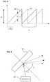
- FIG. 4depicts a detailed view of diffraction grating in the LIDAR sensing system of FIG. 1 in accordance with an illustrative embodiment.
- FIG. 5depicts the LIDAR sensing system of FIG. 1 including a field of view (FOV) expansion system in accordance with an illustrative embodiment.
- FOVfield of view
- FIG. 6depicts the LIDAR sensing system of FIG. 1 including an example rotational system in accordance with an illustrative embodiment.
- FIG. 7depicts a flow chart showing an example method of LIDAR sensing in accordance with an illustrative embodiment.
- Described hereinare systems and methods for LIDAR sensing.
- a LIDAR sensing systemincludes a light source that is controlled to project a collimated beam at various wavelengths.
- An interferometerreceives the collimated beam and projects an object beam corresponding to the collimated beam at a diffraction grating.
- the object beamis diffracted from the diffraction grating at different angles corresponding to the wavelength of the collimated beam.
- the LIDAR sensing systemgenerates a vertical scan (e.g., a two-dimensional scan) of the external environment.
- Various components of the LIDAR sensing systemare then configured to rotate to produce multiple vertical scans, thus generating a three-dimensional scan.
- the LIDAR sensing system 100is shown to include a light source 102 .
- the light source 102may output a collimated beam (e.g., a laser). Additionally, the light source 102 may be configured for adjustment of a wavelength ⁇ of the collimated beam.
- the light source 102may be a tunable laser where (at least) the wavelength ⁇ of the laser is tuned.
- the light source 102may be configured for adjustment of the wavelength ⁇ of the collimated beam across a range. In some examples, the range of wavelengths ⁇ may be between 1.25 ⁇ m and 1.35 ⁇ m.
- the light source 102may be swept across the range of wavelengths k, as will be discussed in greater detail below.
- the LIDAR sensing system 100is also shown to include diffraction grating 104 . While the diffraction grating 104 is included in the LIDAR sensing system 100 of FIG. 1 , in some embodiments, the LIDAR sensing system 100 may not necessarily include diffraction grating 104 .
- the light source 102may be arranged to project components of the collimated beam onto the diffraction grating 104 .
- the diffraction grating 104may be arranged along a path of an object beam corresponding to the collimated beam projected from the light source 102 .
- the object beammay be projected onto the diffraction grating 104 at an incident angle ⁇ 0 (see FIG. 4 ), and the object beam may be diffracted off the diffraction grating 104 at various diffraction angles ⁇ corresponding to a wavelength of the collimated beam from the light source 102 .
- light from the object beamreflects off a surface of an object located in an external environment 106 of the LIDAR sensing system 100 .
- the light reflected off the surface of the objectmay then be detected by the LIDAR sensing system 100 and used for determining a distance to the object.
- the LIDAR sensing system 100may be used to determine a distance to an object 200 in the external environment 106 .
- FIG. 2depicted in FIG. 2 is another example of a LIDAR sensing system 100 including an example of the object 200 being ranged using the LIDAR sensing system 100 .
- the LIDAR sensing system 100is shown to include a detector 202 .
- the detector 202may be arranged to detect light reflected off the object 200 .
- the LIDAR sensing system 100may or may not include diffraction grating 104 .
- the LIDAR sensing system 100may include an interferometer 110 .
- the interferometer 110may be or include components arranged to receive the collimated beam from the light source 102 , and split the collimated beam into one or more component beams. For instance, the interferometer 110 may split the collimated beam into an object beam and a reference beam. The object beam may be projected towards the diffraction grating 104 , and the reference beam may be projected towards a reference mirror 206 .
- the interferometer 110may generate an interference pattern based on a difference between light reflected off surfaces of objects in the external environment 106 and light reflected off the reference mirror 206 .
- the LIDAR sensing system 100may determine a distance to the objects based on the interference pattern.
- the object beam reflected off the object 200may return to the diffraction grating 104 , diffract from the diffraction grating 104 to the interferometer 110 , and the detector 202 may detect an interference pattern from the interferometer 110 .
- the detector 202may generate signals based on the interference pattern.
- the signals from the detector 202may be used for determining the distance to the corresponding objects located in the external environment 106 .
- the LIDAR sensing system 100may include a computing system 112 .
- the computing system 112may include a processor 114 and memory 116 .
- the processor 114may include any component or group of components that are configured to execute, implement, and/or perform any of the processes or functions described herein or any form of instructions to carry out such processes or cause such processes to be performed.
- the processor 114may be a main processor of the LIDAR sensing system 100 . Examples of suitable processors include microprocessors, microcontrollers, DSP processors, and other circuitry that may execute software.
- processorsinclude, but are not limited to, a central processing unit (CPU), an array processor, a vector processor, a digital signal processor (DSP), a field-programmable gate array (FPGA), a programmable logic array (PLA), an application specific integrated circuit (ASIC), programmable logic circuitry, and a controller.
- the processor 114may include at least one hardware circuit (e.g., an integrated circuit) configured to carry out instructions contained in program code. In arrangements in which there is a plurality of processors, such processors may work independently from each other or one or more processors may work in combination with each other.
- the memory 116may be structured for storing one or more types of data.
- the memory 116 storemay include volatile and/or non-volatile memory. Examples of suitable memory 116 include RAM (Random Access Memory), flash memory, ROM (Read Only Memory), PROM (Programmable Read-Only Memory), EPROM (Erasable Programmable Read-Only Memory), EEPROM (Electrically Erasable Programmable Read-Only Memory), registers, magnetic disks, optical disks, hard drives, or any other suitable storage medium, or any combination thereof.
- the memory 116may be a component of the processor 114 , or the memory 116 may be operatively connected to the processor 114 for use thereby. In some arrangements, the memory 116 may be located remotely and accessible by the processor 114 , such as via a suitable communications device.
- the LIDAR sensing system 100may include a light source controller 118 .
- the light source controller 118may be or include computer-readable instructions to control one or more aspects of the light source 102 .
- the light source controller 118may be stored on memory 116 as shown. In other implementations, the light source controller 118 may be stored remotely and accessible by various components of the LIDAR sensing system 100 .
- the processor 114may control the light source 102 in accordance with the instructions from the light source controller 118 .
- the light source controller 118may include instructions to generate a pattern for the collimated beam projected from the light source 102 .
- the collimated beammay be projected from the light source 102 in a pattern 204 having a frequency (e.g., pulsed, saw tooth, etc.).
- the light source controller 118may include instructions to generate, for example, a saw tooth signal 204 that corresponds to the frequency pattern of the collimated beam projected from the light source 102 .
- the frequency patternmay be used for determining a distance between the object and the LIDAR sensing system 100 .
- FIG. 2 and FIG. 3an example of the object 200 being ranged using the LIDAR sensing system 100 and corresponding signal profile are respectively shown. It should be understood that, while described with reference to FIG. 2 and FIG. 3 , the same description may apply to FIG. 1 .
- the LIDAR sensing system 100 shown in FIG. 2the LIDAR sensing system 100 does not include diffraction grating 104 .
- the arrangements described hereincan sweep the frequency of the collimated beam, and calculate as the frequency is incrementally changed for the collimated beam.
- the signal generated by the detector 202may correspond to the signal generated by the light source controller 118 and projected via the light source 102 onto the object 102 .
- the light source 102may be arranged to project the collimated beam both onto the object 200 and the reference mirror 206 (e.g., through the interferometer 110 ).
- the reference mirror 206may be located at a fixed distance D from a point (e.g., from the interferometer 110 , for example).
- the object 200may be located a distance away that is equal to the sum of the fixed distance D and the range R to the object 200 .
- the interferometer 110may generate an interference pattern that corresponds to the reference beam reflected off the reference mirror 206 (e.g., reference signal 300 ) and light which is reflected off the surface of the object 200 (e.g., object signal 302 ).
- the detector 202may detect the interference pattern generated by interferometer 110 and generate signals corresponding to the interference patterns.
- the signals generated by the detector 202may be filtered (e.g., by filter 120 ). Following the signals being generated by the detector 202 (and optional filtering by filter 120 ), the frequency of the signals may be identified.
- the computing system 112may include a signal analyzer 122 .
- the signal analyzer 122may be or include instructions to process signals from the detector 202 (following optional filtering by the filter 120 ) to identify a frequency ⁇ of the signals.
- the signal analyzer 122can be or include a frequency counter to calculate, identify, quantify, or otherwise determine a frequency associated with the signals corresponding to the interference patterns.
- the signal analyzer 122may include computer-readable instructions to perform frequency analysis (e.g., fast Fourier analysis) of the interference pattern to identify frequencies of the signals.
- the signal analyzer 122may include instructions to identify a range of frequencies ⁇ for each of the respective signals.
- the signal analyzer 122may include instructions to identify a time shift ⁇ between the reference signal 300 and object signal 302 .
- the signal analyzer 122may include instructions to identify the ramp period t m for the reference signal 300 and/or object signal 302 .
- the signal analyzer 122may include instructions to identify a beat frequency ⁇ beat at various points in time between the reference signal 300 and object signal 302 . Each (or a subset) of these frequency or other characteristics of the respective signals may be used for determining a distance R to the object 200 .
- the reference signal 300 and object signal 302are shown in FIG. 3 .
- the reference signal 300is detected sooner than the object signal 302 , as the object 200 is located at a distance (e.g. R) further than the reference mirror 206 .
- the LIDAR sensing system 100may determine the distance between the object and the point within the LIDAR sensing system 100 based on the comparison of the reference signal 300 and the object signal 302 .
- the LIDAR sensing system 100may determine the distance according to equation (1):
- Rcf beat 2 ⁇ ( ⁇ ⁇ ⁇ f t m ) ( 1 )
- cthe speed of light
- ⁇ beatis the beat frequency
- ⁇is the range of frequencies
- t mis the ramp period (e.g., the time between t 1 and t 2 ).
- the distance between the object and the same pointis the sum of the fixed distance D and R (as shown in FIG. 2 ). Accordingly, the distance between a single point on a surface of an object (e.g., object 200 ) and a point within the LIDAR sensing system 100 may be determined based on the interference pattern corresponding to the reference signal 300 and object signal 302 .
- the LIDAR sensing system 100may calculate the distance instantaneously (or substantially instantaneously). In implementations such as these, the LIDAR sensing system 100 may calculate the distance according to equation (2):
- Rcf beat 2 ⁇ ( df dt m ) ( 2 ) where df dt m is the instantaneous slope of the frequency ramp, and dt m is the ramp increment. Implementation such as these can compensate for any nonlinearity of frequency ramp of tunable light source 102 , which may increase reliability of the distance calculations.
- the LIDAR sensing system 100may include the interferometer 110 (e.g., a main interferometer) and an auxiliary interferometer.
- the auxiliary interferometermay be substantially the same as the main interferometer.
- the LIDAR sensing system 100may include the detector 202 (e.g., a main detector) and an auxiliary detector.
- the auxiliary detectormay be substantially the same as the main detector.
- the auxiliary interferometermay be arranged to receive the collimated beam from the light source 102 .
- the auxiliary interferometermay split the collimated beam from the light source 102 into two beams, each of which is located at a fixed path length (e.g., a fixed range or distance from the auxiliary interferometer).
- the auxiliary detectormay detect interference patterns from the auxiliary interferometer.
- the interferometer 110may generate the same interference patterns described above, and the auxiliary interferometer may generate interference patterns corresponding to the fixed path length.
- the signal analyzer 122can include instructions for analyzing signals from both the detector 202 and auxiliary detector. The signal analyzer 122 can calculate distances according to equation (3):
- RR o ⁇ f beat f refbeat ( 3 )
- R ois the fixed path length associated with the auxiliary interferometer
- ⁇ ref beatis the beat frequency from the auxiliary interferometer
- ⁇ beatis the beat frequency from the main interferometer (described above).
- the LIDAR sensing system 100may compensate for any nonlinearity of the light source 102 , which may increase accuracy of the distance calculations.
- distancesmay be calculated on a “rolling” basis as the wavelength of the light source 102 is swept across a range. Further, various arrangements and calculations described above may further increase accuracy of the distance calculations (e.g., through different mathematical calculations, additional interferometers, etc.).
- the LIDAR sensing system 100may calculate distances at each interval as the wavelength (and therefore frequency) is changed.
- the wavelength (and frequency)can be incrementally changed.
- the range of wavelengthscan be subdivided into a number of increments.
- the distancecan be calculated (e.g., according to any of the implementations described above, according to time shift or a time difference between receiving an indication of detection of the object beam and reference beam, etc.).
- the computing system 112may include a point cloud generator 124 .
- the point cloud generator 124may be or include instructions to generate a point cloud from various distance measurements.
- Point cloudrefers to a two or three dimensional representation of an external environment 106 of the LIDAR sensing system 100 based on measured distances to various surfaces detected in the external environment 106 .
- the point cloud generator 124may include instructions to store each calculated distance and, for instance, an associated coordinate in a coordinate system. Additionally, where the object beam is moved (e.g., mechanically or electromechanically), further distance measurements may be obtained and thereby producing a two-dimensional scan or three-dimensional scan of the external environment 106 . At least some of these measurements may be used for forming the point cloud.
- the point cloudmay be a 3D point cloud.
- the point cloud generator 124may generate a 360° point cloud. Each of the measured distances and their associated coordinates may be used for forming the point cloud.
- the collimated beam projected from the light source 102may have a wavelength that is swept across a range to change a diffraction angle ⁇ . While described as “swept” herein, it should be understood that the wavelength can be continuously swept, swept at intervals or increments, etc.
- light from the light source 102may be projected onto the diffraction grating 104 (through interferometer 110 ) at an incident angle ⁇ 0 .
- the incident angle ⁇ 0may be fixed. Accordingly, the relationship between the interferometer 110 and the diffraction grating 104 may be maintained throughout various scans, as will be discussed in greater detail below.
- the collimated beammay be projected from the light source 102 at a variable wavelength.
- the light source controller 118may include instructions for changing the wavelength of the collimated beam from the light source 102 .
- the range of wavelengths ⁇ at which the collimated beam from the light source 102 may be sweptmay be between 1.25 ⁇ m and 1.35 ⁇ m. As the wavelength ⁇ of the collimated beam projected from the light source 102 is swept, the diffraction angle ⁇ changes.
- the collimated beam projected from the light source 102may have a linewidth of 1 MHz. In implementations such as these, the coherence length may be 300 m (or a single path range of 150 m). Additionally, the collimated beam projected from the light source 102 may have a tuning range of 1.6 GHz. In these implementations, the resolution may be 9 cm. In each of these implementations, the LIDAR sensing system 100 may satisfy, at least, current standard requirements for LIDAR in many autonomous driving applications (e.g., ranging of 100 m and a resolution of less than 10 cm).
- the LIDAR sensing system 100may further include components to increase the field of view along an axis.
- the LIDAR sensing systemmay include a field of view (FOV) expansion system 500 .
- the FOV expansion system 500may include a rotational element 502 and a mirror 504 .
- the rotational element 502may be operatively connected to mirror 504 .
- the rotational element 502may be operatively connected to a swivel 506 for the mirror 504 .
- the rotational element 502may be a micro-electromechanical system (MEMS) driver.
- MEMSmicro-electromechanical system
- the diffraction grating 104may be arranged to diffract the object beam towards the mirror 504 .
- the rotational element 502may then rotate the mirror 504 to further expand the field of view of the LIDAR sensing system 100 along the axis.
- the rotational element 502may rotate the mirror 504 a number of degrees along the vertical axis. In so doing, the object beam diffracted from the diffraction grating 104 may be reflected off the mirror 504 at an angular range 508 corresponding to the rotation of the mirror 504 .
- the field of view 510 of the LIDAR sensing system 100may be defined by the degree of rotation of the mirror 504 and the change in wavelength of the collimated beam from the light source 102 .
- the LIDAR sensing system 100may acquire data corresponding to various distances to objects in the external environment 106 (e.g., along the axis).
- the LIDAR sensing system 100may execute a scan (e.g., a two-dimensional scan) of the external environment 106 along an axis (e.g., the vertical axis of the external environment 106 ).
- a scane.g., a two-dimensional scan
- an axise.g., the vertical axis of the external environment 106
- the LIDAR sensing system 100may generate additional vertical scans. These additional vertical scans may be combined to generate a three-dimensional scan of the external environment 106 (e.g., via the point cloud generator 124 ).
- Such a three-dimensional scanmay have several practical applications including, but not limited to, object detection and tracking, advanced driving assistance systems, autonomous driving, etc. Additionally, such a three-dimensional scan may be used in other fields outside of vehicle applications including, for instance, generation of three-dimensional maps.
- the LIDAR sensing system 100may include a rotational system 126 .
- the rotational system 126may be or include any component or group of components configured to rotate one or more elements of the LIDAR sensing system 100 .
- the rotational system 126may be used for generating a three-dimensional data and a resulting three-dimensional point cloud of the external environment 106 .
- the rotational system 126may include a motor 128 , one or more rotational drivers 130 , and one or more rotary stages 132 .
- the motor 128may be a DC motor.
- the motor 128may be connected to (e.g., via a shaft) the rotational driver 130 .
- the motor 128may be configured to rotate the rotational driver 130 .
- the rotational driver 130may be or include one or more gears, pulleys, and/or other components configured to be rotated by the motor 128 and, as a result, rotate the rotary stage 132 .
- the rotary stage 132may be configured to support (and thereby rotate) one or more elements of the LIDAR sensing system 100 .
- the rotary stage 132may support the diffraction grating 104 , the FOV expansion system 500 (where included), etc., which may be mounted thereto.
- the rotary stage 132may include an aperture 134 to allow the object beam to pass through the rotary stage 132 and onto the diffraction grating 104 .
- the motor 128may be configured to rotate about an axis 136 as shown. When the motor 128 rotates about the axis 136 , the motor 128 may rotate the rotational driver 130 about another axis. In the example shown, the motor 128 causes the rotational driver 130 to rotate about the same axis 136 . However, the motor 128 may cause the rotational driver 130 to rotate along an axis that is different from axis 136 . Accordingly, the present disclosure is not limited to the particular arrangement shown in FIG. 1 .
- the rotational driver 130may cause the rotary stage 132 to rotate about another axis 138 .
- the rotational driver 130may cause the rotary stage 132 to rotate a full 360° about the axis 138 .
- the rotation driver 130may cause the rotary stage 132 to rotate less than (or greater than) the full 360° about the axis 138 .
- LIDAR sensing system 100may generate additional scans along the vertical axis (e.g., through controlling the light source 102 ). Each of these scans may generate distance data associated with various objects located along the vertical axis.
- the point cloud generator 124may include instructions to generate a three-dimensional point cloud based on each of these vertical scans.
- the rotational system 126may include a rotational element 502 and mirror 504 .
- the rotational element 502 and mirror 504may be similar to those described above with reference to FIG. 5 .
- the LIDAR sensing system 100may include both the FOV expansion system 500 and rotational system 126 , in which case the LIDAR sensing system 100 includes two rotational elements 502 and two mirrors 504 .
- the rotational element 502may be arranged to rotate the mirror 504 about axis 602 (e.g., an axis 602 parallel to the vertical axis).
- the mirror 504may be rotated about the axis 602 , and subsequent vertical scans may be generated of the external environment 106 (e.g., shown by box 604 ). Each of these vertical scans may be used to generate a point cloud, as described above.
- FIG. 7provides only one example of LIDAR scanning. Accordingly, the following disclosure should not be limited to each and every function block shown in FIG. 7 . To the contrary, the method does not require each and every function block shown in FIG. 7 . In some examples, the method may include additional function blocks. Further, the method does not need to be performed in the same chronological order shown in FIG. 7 .
- FIG. 7a flow chart is shown to depict an example method 700 of LIDAR scanning is shown.
- the method 700may begin. For example, the method 700 may begin when an initialization signal (e.g., from a user) is received by the various components/systems described herein. As another example, the method 700 may begin when a vehicle is started (e.g., when the LIDAR sensing system 100 is a component of the vehicle). The method 700 may proceed to operation 704 .
- an initialization signale.g., from a user
- a vehiclee.g., when the LIDAR sensing system 100 is a component of the vehicle.
- the method 700may proceed to operation 704 .
- the method 700may include controlling the light source 102 to project the collimated beam at a first wavelength at a first time.
- the collimated beammay be split by interferometer 110 into the object beam and reference beam.
- the object beammay be projected onto the diffraction grating 104 .
- the processor 114may control the light source 102 in accordance with the instructions from the light source controller 118 .
- the object beammay be diffracted from the diffraction grating 104 at a first diffraction angle ⁇ .
- the object beammay be diffracted from the diffraction grating 104 at the first diffraction angle ⁇ in accordance with the wavelength of the collimated beam.
- the method 700may proceed to operation 706 .
- the method 700may further include generating one or more control signals FOV expansion system 500 to control the rotational element 502 to rotate the mirror 504 in a first direction.
- the collimated beammay be reflected off the mirror 504 into the external environment 106 at a first angular range 508 corresponding to a degree of rotation of the mirror 504 .
- the field of view for the LIDAR sensing system 100may be defined by the first and second diffraction angle and the first angular range 508 .
- the method 700may include receiving a signal corresponding to a first interference pattern from the detector 202 .
- the interferometer 110may generate the first interference pattern based on light reflected off objects in the external environment 106 and the reference mirror 206 .
- the detector 202may detect the interference pattern, and may generate a signal corresponding to the interference pattern.
- the first interference patternmay be associated with the collimated beam projected at operation 704 .
- the method 700may proceed to operation 708 .
- the method 700may include calculating a first distance associated with the first interference pattern from operation 706 .
- the signal analyzer 122can include instructions for calculating the first distance (e.g., via any of equations 1-3).
- the signal analyzer 122can include instructions for analyzing the signal from function block 706 to determine various signal characteristics (e.g., frequency, temporal, or other characteristics).
- the signal analyzer 122can include instructions for calculating the first distance based on various characteristics of the analyzed signal.
- the method 700may proceed to operation 710 .
- the method 700may include controlling the light source 102 to project the collimated beam at a second wavelength at a second time. Operation 710 may be similar to operation 704 . However, the second wavelength may be different from the first wavelength. Accordingly, the object beam may be diffracted from the diffraction grating 104 at a second diffraction angle ⁇ different from the first diffraction angle ⁇ . The object beam may be diffracted from the diffraction grating 104 at the second diffraction angle ⁇ in accordance with the wavelength of the collimated beam.
- the method 700may include calculating additional distances in substantially the same manner as described above with reference to operation 708 .
- the method 700may include calculating distances associated with various objects located along the axis in the external environment 106 .
- the distancesmay be calculated based on interference patterns generated by the interferometer 110 and detected by the detector 202 .
- the distancesmay be calculated on a “rolling” basis. For instance, as the light source 102 is controlled to sweep the collimated beam across a range of wavelengths, the method 700 may include calculating distances as the collimated beam is swept across the range of wavelengths.
- the method 700may further include generating one or more control signals for the FOV expansion system 500 to control the rotational element 502 to rotate the mirror 504 in a second direction.
- the object beammay be reflected off the mirror 504 into the external environment 106 at a second angular range 508 corresponding to a degree of rotation of the mirror 504 .
- the field of view for the LIDAR sensing system 100may be defined by the first and second diffraction angle and the second angular range 508 .
- the field of view for the LIDAR sensing system 100may be defined by the first and second diffraction angle and the first and second angular range 508 .
- the method 700may further include generating one or more control signals for the rotational system 126 to one or more components of the LIDAR sensing system 100 about another axis to a second position. In implementations such as these, the method 700 may further include generating a second scan (and additional scans) of adjacent portions of the external environment 106 (e.g., through executing operations 702 through 710 when the rotary stage 132 is located at the second position).
- the method 700may include generating a point cloud map based on distances (including the first distance calculated at operation 708 ).
- the point cloud mapmay be a 360° point cloud map.
- the point cloud mapmay be a 360° point cloud map when the rotary stage is rotated 360° about the second axis.
Landscapes
- Engineering & Computer Science (AREA)
- Physics & Mathematics (AREA)
- Computer Networks & Wireless Communication (AREA)
- General Physics & Mathematics (AREA)
- Radar, Positioning & Navigation (AREA)
- Remote Sensing (AREA)
- Electromagnetism (AREA)
- Optical Radar Systems And Details Thereof (AREA)
Abstract
Description
where c is the speed of light, ƒbeatis the beat frequency, Δƒ is the range of frequencies, and tmis the ramp period (e.g., the time between t1and t2). Where the fixed distance D between the
is the instantaneous slope of the frequency ramp, and dtmis the ramp increment. Implementation such as these can compensate for any nonlinearity of frequency ramp of tunable
where Rois the fixed path length associated with the auxiliary interferometer, ƒref beatis the beat frequency from the auxiliary interferometer, and ƒbeatis the beat frequency from the main interferometer (described above). In implementations such as these, the
λ=d(sin α0−sin β) (4)
where the groove frequency d of grating in the
Claims (20)
Priority Applications (6)
| Application Number | Priority Date | Filing Date | Title |
|---|---|---|---|
| US15/954,878US11067671B2 (en) | 2018-04-17 | 2018-04-17 | LIDAR sensing arrangements |
| US16/278,582US10838047B2 (en) | 2018-04-17 | 2019-02-18 | Systems and methods for LIDAR scanning of an environment over a sweep of wavelengths |
| JP2020556228AJP7233745B2 (en) | 2018-04-17 | 2019-04-16 | lidar sensing device |
| PCT/US2019/027671WO2019204301A1 (en) | 2018-04-17 | 2019-04-16 | Lidar sensing arrangements |
| DE112019002028.5TDE112019002028T5 (en) | 2018-04-17 | 2019-04-16 | LIDAR DETECTION ARRANGEMENTS |
| US17/099,220US11994628B2 (en) | 2018-04-17 | 2020-11-16 | Systems and methods for scanning of an environment using a frequency-varied beam split into a reference beam and object beam |
Applications Claiming Priority (1)
| Application Number | Priority Date | Filing Date | Title |
|---|---|---|---|
| US15/954,878US11067671B2 (en) | 2018-04-17 | 2018-04-17 | LIDAR sensing arrangements |
Related Child Applications (1)
| Application Number | Title | Priority Date | Filing Date |
|---|---|---|---|
| US16/278,582Continuation-In-PartUS10838047B2 (en) | 2018-04-17 | 2019-02-18 | Systems and methods for LIDAR scanning of an environment over a sweep of wavelengths |
Publications (2)
| Publication Number | Publication Date |
|---|---|
| US20190317194A1 US20190317194A1 (en) | 2019-10-17 |
| US11067671B2true US11067671B2 (en) | 2021-07-20 |
Family
ID=68161609
Family Applications (1)
| Application Number | Title | Priority Date | Filing Date |
|---|---|---|---|
| US15/954,878Active2039-11-18US11067671B2 (en) | 2018-04-17 | 2018-04-17 | LIDAR sensing arrangements |
Country Status (1)
| Country | Link |
|---|---|
| US (1) | US11067671B2 (en) |
Cited By (9)
| Publication number | Priority date | Publication date | Assignee | Title |
|---|---|---|---|---|
| US20220334260A1 (en)* | 2021-04-16 | 2022-10-20 | Santec Corporation | Systems and methods for lidar sensing |
| US11486792B2 (en) | 2020-06-05 | 2022-11-01 | Santec Corporation | Tunable light source for optical fiber proximity and testing |
| US11513228B2 (en)* | 2020-03-05 | 2022-11-29 | Santec Corporation | Lidar sensing arrangements |
| US11933967B2 (en) | 2019-08-22 | 2024-03-19 | Red Creamery, LLC | Distally actuated scanning mirror |
| US11994628B2 (en) | 2018-04-17 | 2024-05-28 | santec Holdings Corporation | Systems and methods for scanning of an environment using a frequency-varied beam split into a reference beam and object beam |
| US12123950B2 (en) | 2016-02-15 | 2024-10-22 | Red Creamery, LLC | Hybrid LADAR with co-planar scanning and imaging field-of-view |
| US12313883B2 (en) | 2023-03-03 | 2025-05-27 | santec Holdings Corporation | Photonic beam steering device with wavelength sweep |
| US12399279B1 (en) | 2016-02-15 | 2025-08-26 | Red Creamery Llc | Enhanced hybrid LIDAR with high-speed scanning |
| US12399278B1 (en) | 2016-02-15 | 2025-08-26 | Red Creamery Llc | Hybrid LIDAR with optically enhanced scanned laser |
Families Citing this family (4)
| Publication number | Priority date | Publication date | Assignee | Title |
|---|---|---|---|---|
| WO2019232585A1 (en)* | 2018-06-07 | 2019-12-12 | Baraja Pty Ltd | An optical beam director |
| US12210122B2 (en)* | 2020-08-26 | 2025-01-28 | Infineon Technologies Ag | Mirror movement and laser shoot pattern compensation for frequency-modulated continous-wave (FMCW) LIDAR |
| CN112327319B (en)* | 2020-11-09 | 2023-12-19 | 之江实验室 | Solid-state lidar detection method and system based on cyclic frequency shift loop |
| CN112630795B (en)* | 2020-12-24 | 2023-05-26 | 浙江大学滨海产业技术研究院 | Three-dimensional point cloud data synthesis system based on 2D laser radar |
Citations (114)
| Publication number | Priority date | Publication date | Assignee | Title |
|---|---|---|---|---|
| US4466699A (en) | 1982-01-22 | 1984-08-21 | Honeywell Inc. | Curved tunable Fabry-Perot filter |
| US5022745A (en) | 1989-09-07 | 1991-06-11 | Massachusetts Institute Of Technology | Electrostatically deformable single crystal dielectrically coated mirror |
| US5319668A (en) | 1992-09-30 | 1994-06-07 | New Focus, Inc. | Tuning system for external cavity diode laser |
| US5372135A (en) | 1991-12-31 | 1994-12-13 | Vivascan Corporation | Blood constituent determination based on differential spectral analysis |
| US5430574A (en) | 1994-07-25 | 1995-07-04 | Litton Systems, Inc. | Rugged optical filter and switch for communication networks |
| US5537162A (en) | 1993-12-17 | 1996-07-16 | Carl Zeiss, Inc. | Method and apparatus for optical coherence tomographic fundus imaging without vignetting |
| US5561523A (en) | 1994-02-17 | 1996-10-01 | Vaisala Oy | Electrically tunable fabry-perot interferometer produced by surface micromechanical techniques for use in optical material analysis |
| US5979760A (en) | 1997-06-27 | 1999-11-09 | Accu-Sort Systems, Inc. | Scanner with linear actuator based lens positioning system |
| US5982963A (en) | 1997-12-15 | 1999-11-09 | University Of Southern California | Tunable nonlinearly chirped grating |
| US6070093A (en) | 1997-12-02 | 2000-05-30 | Abbott Laboratories | Multiplex sensor and method of use |
| US6111645A (en) | 1991-04-29 | 2000-08-29 | Massachusetts Institute Of Technology | Grating based phase control optical delay line |
| US6134003A (en) | 1991-04-29 | 2000-10-17 | Massachusetts Institute Of Technology | Method and apparatus for performing optical measurements using a fiber optic imaging guidewire, catheter or endoscope |
| US6160826A (en) | 1991-04-29 | 2000-12-12 | Massachusetts Institute Of Technology | Method and apparatus for performing optical frequency domain reflectometry |
| US6275718B1 (en) | 1999-03-23 | 2001-08-14 | Philip Lempert | Method and apparatus for imaging and analysis of ocular tissue |
| US6373632B1 (en) | 2000-03-03 | 2002-04-16 | Axsun Technologies, Inc. | Tunable Fabry-Perot filter |
| US20020163948A1 (en) | 2001-05-01 | 2002-11-07 | The Furukawa Electric Co., Ltd. | Semiconductor laser device having a diffraction grating on a light emission side |
| US6485413B1 (en) | 1991-04-29 | 2002-11-26 | The General Hospital Corporation | Methods and apparatus for forward-directed optical scanning instruments |
| US6501551B1 (en) | 1991-04-29 | 2002-12-31 | Massachusetts Institute Of Technology | Fiber optic imaging endoscope interferometer with at least one faraday rotator |
| US6556853B1 (en) | 1995-12-12 | 2003-04-29 | Applied Spectral Imaging Ltd. | Spectral bio-imaging of the eye |
| US6564087B1 (en) | 1991-04-29 | 2003-05-13 | Massachusetts Institute Of Technology | Fiber optic needle probes for optical coherence tomography imaging |
| US20030089778A1 (en) | 1998-03-24 | 2003-05-15 | Tsikos Constantine J. | Method of and system for automatically producing digital images of a moving object, with pixels having a substantially uniform white level independent of the velocity of said moving object |
| US20040036838A1 (en) | 2002-06-28 | 2004-02-26 | Podoleanu Adrian Gh. | Optical mapping apparatus with adjustable depth resolution and multiple functionality |
| US6725073B1 (en) | 1999-08-17 | 2004-04-20 | Board Of Regents, The University Of Texas System | Methods for noninvasive analyte sensing |
| US20050171438A1 (en) | 2003-12-09 | 2005-08-04 | Zhongping Chen | High speed spectral domain functional optical coherence tomography and optical doppler tomography for in vivo blood flow dynamics and tissue structure |
| US20050201432A1 (en) | 2004-03-10 | 2005-09-15 | Santec Corporation | Wide bandwidth light source |
| US20050213103A1 (en) | 2004-03-29 | 2005-09-29 | Everett Matthew J | Simple high efficiency optical coherence domain reflectometer design |
| US20060105209A1 (en) | 2004-11-12 | 2006-05-18 | Jurgen Thyroff | System and method for drying a fuel cell stack at system shutdown |
| US20060109872A1 (en) | 2004-11-24 | 2006-05-25 | Sanders Scott T | Modeless wavelength-agile laser |
| JP2006202543A (en) | 2005-01-18 | 2006-08-03 | Nissan Motor Co Ltd | Operation method of fuel cell system |
| US7099358B1 (en) | 2005-08-05 | 2006-08-29 | Santec Corporation | Tunable laser light source |
| US20060215713A1 (en) | 2005-03-28 | 2006-09-28 | Axsun Technologies, Inc. | Laser with tilted multi spatial mode resonator tuning element |
| US20070040033A1 (en) | 2005-11-18 | 2007-02-22 | Outland Research | Digital mirror system with advanced imaging features and hands-free control |
| US20070076217A1 (en) | 2005-10-05 | 2007-04-05 | Chris Baker | Optical coherence tomography for eye-length measurement |
| US20070081166A1 (en) | 2005-09-29 | 2007-04-12 | Bioptigen, Inc. | Portable Optical Coherence Tomography (OCT) Devices and Related Systems |
| US7231243B2 (en) | 2000-10-30 | 2007-06-12 | The General Hospital Corporation | Optical methods for tissue analysis |
| US20070133647A1 (en) | 2005-09-30 | 2007-06-14 | Andrew Daiber | Wavelength modulated laser |
| US20070141418A1 (en) | 2004-03-17 | 2007-06-21 | Toyota Jidosha Kabushiki Kaisha | Fuel cell system control device |
| US20070233396A1 (en) | 2005-09-29 | 2007-10-04 | The General Hospital Corporation | Method and apparatus for optical imaging via spectral encoding |
| US20070263226A1 (en) | 2006-05-15 | 2007-11-15 | Eastman Kodak Company | Tissue imaging system |
| US20070291277A1 (en) | 2006-06-20 | 2007-12-20 | Everett Matthew J | Spectral domain optical coherence tomography system |
| US7324214B2 (en) | 2003-03-06 | 2008-01-29 | Zygo Corporation | Interferometer and method for measuring characteristics of optically unresolved surface features |
| US7323680B2 (en) | 2005-04-12 | 2008-01-29 | Santec Corporation | Optical deflection probe and optical deflection probe device |
| US7352783B2 (en) | 2004-09-10 | 2008-04-01 | Santec Corporation | Tunable fiber laser light source |
| US20080097194A1 (en) | 2006-10-18 | 2008-04-24 | Milner Thomas E | Hemoglobin contrast in magneto-motive optical doppler tomography, optical coherence tomography, and ultrasound imaging methods and apparatus |
| US7382809B2 (en) | 2005-02-25 | 2008-06-03 | Santec Corporation | Tunable fiber laser light source |
| US7414779B2 (en) | 2005-01-20 | 2008-08-19 | Massachusetts Institute Of Technology | Mode locking methods and apparatus |
| JP2008188047A (en) | 2007-01-31 | 2008-08-21 | Nidek Co Ltd | Axial length measuring device |
| US7428057B2 (en) | 2005-01-20 | 2008-09-23 | Zygo Corporation | Interferometer for determining characteristics of an object surface, including processing and calibration |
| US20080269575A1 (en) | 2005-02-17 | 2008-10-30 | Iddan Gavriel J | Method and Apparatus for Monitoring Bodily Analytes |
| US20090022181A1 (en) | 2007-07-20 | 2009-01-22 | International Business Machines Corporation | Optical spectral filtering and dispersion control for wavelength multiplexed laser sources using fiber bragg gratings |
| US20090079993A1 (en) | 2005-11-22 | 2009-03-26 | Shofu Inc. | Dental Optical Coherence Tomograph |
| US20090103050A1 (en) | 2007-10-19 | 2009-04-23 | Wavetec Vision Systems, Inc. | Optical instrument alignment system |
| US20090169928A1 (en) | 2007-12-27 | 2009-07-02 | Nissan Motor Co., Ltd. | Fuel cell system and control method thereof |
| US20090247853A1 (en) | 2008-03-31 | 2009-10-01 | Nellcor Puritan Bennett Llc | Non-Invasive Total Hemoglobin Measurement by Spectral Optical Coherence Tomography |
| US20090268020A1 (en) | 2008-04-23 | 2009-10-29 | Bioptigen, Inc. | Optical Coherence Tomography (OCT) Imaging Systems for Use in Pediatric Ophthalmic Applications and Related Methods and Computer Program Products |
| US20090290613A1 (en) | 2008-05-21 | 2009-11-26 | Applied Optoelectronics, Inc. | External cavity laser assembly including external chirped exit reflector for improved linearity |
| US7701588B2 (en) | 2006-04-11 | 2010-04-20 | Santec Corporation | Swept source type optical coherent tomography system |
| US20100110171A1 (en) | 2008-11-05 | 2010-05-06 | Nidek Co., Ltd. | Ophthalmic photographing apparatus |
| US7725169B2 (en) | 2005-04-15 | 2010-05-25 | The Board Of Trustees Of The University Of Illinois | Contrast enhanced spectroscopic optical coherence tomography |
| US20100157308A1 (en) | 2005-02-04 | 2010-06-24 | University Of Florida Research Foundation, Inc. | Single fiber endoscopic full-field optical coherence tomography (oct) imaging probe |
| JP2010172538A (en) | 2009-01-30 | 2010-08-12 | Nidek Co Ltd | Ophthalmic ultrasonic diagnostic apparatus |
| US20100246612A1 (en) | 2007-10-25 | 2010-09-30 | Nec Corporation | Mode-locked laser |
| US20100253908A1 (en) | 2006-04-24 | 2010-10-07 | Hammer Daniel X | Stabilized Retinal Imaging With Adaptive Optics |
| US20100284021A1 (en) | 2007-09-28 | 2010-11-11 | Carl Zeiss Meditec Ag | Short coherence interferometer |
| US7835010B2 (en) | 2007-04-13 | 2010-11-16 | Santec Corporation | Optical coherence tomography system and optical coherence tomography method |
| US7865231B2 (en) | 2001-05-01 | 2011-01-04 | The General Hospital Corporation | Method and apparatus for determination of atherosclerotic plaque type by measurement of tissue optical properties |
| US7869057B2 (en) | 2002-09-09 | 2011-01-11 | Zygo Corporation | Multiple-angle multiple-wavelength interferometer using high-NA imaging and spectral analysis |
| US7884945B2 (en) | 2005-01-21 | 2011-02-08 | Massachusetts Institute Of Technology | Methods and apparatus for optical coherence tomography scanning |
| US20110112385A1 (en) | 2008-04-21 | 2011-05-12 | Academisch Medisch Centrum | Apparatus and method for dating a body sample |
| US7961312B2 (en) | 2007-08-13 | 2011-06-14 | C8 Medisensors Inc. | Calibrated analyte concentration measurements in mixtures |
| US20110228218A1 (en) | 2008-11-26 | 2011-09-22 | Carl Zeiss Surgical Gmbh | Imaging system |
| US20110235045A1 (en) | 2008-10-10 | 2011-09-29 | Universitaet Stuttgart | Method and apparatus for interferometry |
| US8036727B2 (en) | 2004-08-11 | 2011-10-11 | Glt Acquisition Corp. | Methods for noninvasively measuring analyte levels in a subject |
| US20110255054A1 (en) | 2008-12-23 | 2011-10-20 | Carl Zeiss Meditec Ag | Device for swept-source optical coherence domain reflectometry |
| US20110299034A1 (en) | 2008-07-18 | 2011-12-08 | Doheny Eye Institute | Optical coherence tomography- based ophthalmic testing methods, devices and systems |
| US20120013849A1 (en) | 2010-07-13 | 2012-01-19 | University Of Kent At Canterbury | Apparatus and method of monitoring and measurement using spectral low coherence interferometry |
| US20120026466A1 (en) | 2006-01-20 | 2012-02-02 | Clarity Medical Systems, Inc. | Large diopter range real time sequential wavefront sensor |
| US8115934B2 (en) | 2008-01-18 | 2012-02-14 | The Board Of Trustees Of The University Of Illinois | Device and method for imaging the ear using optical coherence tomography |
| US20120133950A1 (en) | 2010-11-26 | 2012-05-31 | Canon Kabushiki Kaisha | Tomographic imaging method and tomographic imaging apparatus |
| US20120136259A1 (en) | 2006-06-05 | 2012-05-31 | Volcano Corporation | Polarization-sensitive spectral interferometry |
| WO2012075126A2 (en) | 2010-11-30 | 2012-06-07 | The Board Of Regents Of The University Of Texas System | Methods and apparatus related to photothermal optical coherence tomography (oct) |
| US20120188555A1 (en) | 2011-01-21 | 2012-07-26 | Duke University | Systems and methods for complex conjugate artifact resolved optical coherence tomography |
| US8315282B2 (en) | 2005-01-20 | 2012-11-20 | Massachusetts Institute Of Technology | Fourier domain mode locking: method and apparatus for control and improved performance |
| DE102011114797A1 (en) | 2011-10-01 | 2013-04-04 | Daimler Ag | Method for operating fuel cell system utilized in passenger car to generate electrical driving power, involves recirculating unreacted fuel into fuel, and heating nozzle of fuel jet pump only when fuel is not made to flow through jet pump |
| US8427649B2 (en) | 2009-05-15 | 2013-04-23 | Michigan Aerospace Corporation | Range imaging lidar |
| US8500279B2 (en) | 2008-11-06 | 2013-08-06 | Carl Zeiss Meditec, Inc. | Variable resolution optical coherence tomography scanner and method for using same |
| US20130265545A1 (en) | 2012-04-05 | 2013-10-10 | Bioptigen, Inc. | Surgical Microscopes Using Optical Coherence Tomography and Related Systems and Methods |
| WO2013168149A1 (en) | 2012-05-09 | 2013-11-14 | Technion Research & Development Foundation Limited | System and method for optical coherence tomography |
| US8625104B2 (en) | 2009-10-23 | 2014-01-07 | Bioptigen, Inc. | Systems for comprehensive fourier domain optical coherence tomography (FDOCT) and related methods |
| US20140051952A1 (en) | 2008-03-04 | 2014-02-20 | Glt Acquisition Corp. | Flowometry in optical coherence tomography for analyte level estimation |
| US8690328B1 (en) | 2013-01-30 | 2014-04-08 | Santec Corporation | Methods and devices for ophthalmic optical tomographic image display |
| US20140111774A1 (en) | 2012-10-24 | 2014-04-24 | Canon Kabushiki Kaisha | Ophthalmologic apparatus, ophthalmologic control method, and recording medium |
| US20140228681A1 (en) | 2012-02-03 | 2014-08-14 | Oregon Health & Science University | In vivo optical flow imaging |
| US20140293290A1 (en) | 2010-11-08 | 2014-10-02 | Netra Systems Inc. | Method and System for Compact Optical Coherence Tomography |
| US20140336479A1 (en) | 2013-05-07 | 2014-11-13 | Hideo Ando | Detection method of life activity, measuring device of life activity, transmission method of life activity detection signal, or service based on life activity information |
| US20150177380A1 (en)* | 2011-08-16 | 2015-06-25 | California Institute Of Technology | Three-dimensional tomographic imaging camera |
| US20150223681A1 (en) | 2012-08-30 | 2015-08-13 | The Board Of Regents Of The University Of Texas Systems | Method and Apparatus for Ultrafast Multi-Wavelength Photothermal Optical Coherence Tomography (OCT) |
| WO2015121756A2 (en) | 2014-01-21 | 2015-08-20 | Santec Corporation | Optical coherence tomography system with multiple sample paths |
| US9163930B2 (en) | 2009-09-22 | 2015-10-20 | Bioptigen, Inc. | Systems for extended depth frequency domain optical coherence tomography (FDOCT) and related methods |
| US20150348287A1 (en) | 2014-04-28 | 2015-12-03 | Northwestern University | Devices, methods, and systems of functional optical coherence tomography |
| US9295391B1 (en) | 2000-11-10 | 2016-03-29 | The General Hospital Corporation | Spectrally encoded miniature endoscopic imaging probe |
| US9335154B2 (en) | 2013-02-01 | 2016-05-10 | Duke University | Systems and methods of angle-resolved low coherence interferometry based optical correlation |
| US20160178346A1 (en) | 2009-02-19 | 2016-06-23 | Netra Systems, Inc | Method and System for Low Coherence Interferometry |
| US20160259038A1 (en) | 2015-03-05 | 2016-09-08 | Facet Technology Corp. | Methods and Apparatus for Increased Precision and Improved Range in a Multiple Detector LiDAR Array |
| US20160356881A1 (en) | 2014-04-11 | 2016-12-08 | Facet Technology Corp. | Methods and apparatus for object detection and identification in a multiple detector lidar array |
| US20170090031A1 (en) | 2015-09-28 | 2017-03-30 | Federico Collarte Bondy | Spatial profiling system and method |
| WO2017176901A1 (en) | 2016-04-07 | 2017-10-12 | Arizona Board Of Regents On Behalf Of The University Of Arizona | Diffraction-based light beam scanner |
| US9851433B2 (en) | 2013-12-19 | 2017-12-26 | DSCG Solutions, Inc. | Single laser LIDAR system |
| US20180088236A1 (en) | 2015-11-30 | 2018-03-29 | Luminar Technologies, Inc. | Lidar system |
| US20180128594A1 (en) | 2016-11-09 | 2018-05-10 | Korea Basic Science Institute | Common-path optical fiber-based handheld parallel optical coherence tomography (oct) apparatus |
| US20190257927A1 (en)* | 2018-02-16 | 2019-08-22 | Xiaotian Steve Yao | Optical sensing based on wavelength division multiplexed (wdm) light at different wavelengths in light detection and ranging lidar systems |
| WO2019204301A1 (en) | 2018-04-17 | 2019-10-24 | Santec Corporation | Lidar sensing arrangements |
| US20200292673A1 (en) | 2019-01-04 | 2020-09-17 | Blackmore Sensors & Analytics, Llc | Lidar system including multifaceted deflector |
| US20200292674A1 (en) | 2019-01-04 | 2020-09-17 | Blackmore Sensors & Analytics, Llc | Systems and methods for refractive beam-steering |
- 2018
- 2018-04-17USUS15/954,878patent/US11067671B2/enactiveActive
Patent Citations (123)
| Publication number | Priority date | Publication date | Assignee | Title |
|---|---|---|---|---|
| US4466699A (en) | 1982-01-22 | 1984-08-21 | Honeywell Inc. | Curved tunable Fabry-Perot filter |
| US5022745A (en) | 1989-09-07 | 1991-06-11 | Massachusetts Institute Of Technology | Electrostatically deformable single crystal dielectrically coated mirror |
| US6485413B1 (en) | 1991-04-29 | 2002-11-26 | The General Hospital Corporation | Methods and apparatus for forward-directed optical scanning instruments |
| US6111645A (en) | 1991-04-29 | 2000-08-29 | Massachusetts Institute Of Technology | Grating based phase control optical delay line |
| US6134003A (en) | 1991-04-29 | 2000-10-17 | Massachusetts Institute Of Technology | Method and apparatus for performing optical measurements using a fiber optic imaging guidewire, catheter or endoscope |
| US6160826A (en) | 1991-04-29 | 2000-12-12 | Massachusetts Institute Of Technology | Method and apparatus for performing optical frequency domain reflectometry |
| US6421164B2 (en) | 1991-04-29 | 2002-07-16 | Massachusetts Institute Of Technology | Interferometeric imaging with a grating based phase control optical delay line |
| US6282011B1 (en) | 1991-04-29 | 2001-08-28 | Massachusetts Institute Of Technology | Grating based phase control optical delay line |
| US6501551B1 (en) | 1991-04-29 | 2002-12-31 | Massachusetts Institute Of Technology | Fiber optic imaging endoscope interferometer with at least one faraday rotator |
| US6564087B1 (en) | 1991-04-29 | 2003-05-13 | Massachusetts Institute Of Technology | Fiber optic needle probes for optical coherence tomography imaging |
| US5372135A (en) | 1991-12-31 | 1994-12-13 | Vivascan Corporation | Blood constituent determination based on differential spectral analysis |
| US5319668A (en) | 1992-09-30 | 1994-06-07 | New Focus, Inc. | Tuning system for external cavity diode laser |
| US5537162A (en) | 1993-12-17 | 1996-07-16 | Carl Zeiss, Inc. | Method and apparatus for optical coherence tomographic fundus imaging without vignetting |
| US5561523A (en) | 1994-02-17 | 1996-10-01 | Vaisala Oy | Electrically tunable fabry-perot interferometer produced by surface micromechanical techniques for use in optical material analysis |
| US5430574A (en) | 1994-07-25 | 1995-07-04 | Litton Systems, Inc. | Rugged optical filter and switch for communication networks |
| US6556853B1 (en) | 1995-12-12 | 2003-04-29 | Applied Spectral Imaging Ltd. | Spectral bio-imaging of the eye |
| US5979760A (en) | 1997-06-27 | 1999-11-09 | Accu-Sort Systems, Inc. | Scanner with linear actuator based lens positioning system |
| US6070093A (en) | 1997-12-02 | 2000-05-30 | Abbott Laboratories | Multiplex sensor and method of use |
| US5982963A (en) | 1997-12-15 | 1999-11-09 | University Of Southern California | Tunable nonlinearly chirped grating |
| US20030089778A1 (en) | 1998-03-24 | 2003-05-15 | Tsikos Constantine J. | Method of and system for automatically producing digital images of a moving object, with pixels having a substantially uniform white level independent of the velocity of said moving object |
| US6275718B1 (en) | 1999-03-23 | 2001-08-14 | Philip Lempert | Method and apparatus for imaging and analysis of ocular tissue |
| US6725073B1 (en) | 1999-08-17 | 2004-04-20 | Board Of Regents, The University Of Texas System | Methods for noninvasive analyte sensing |
| US6373632B1 (en) | 2000-03-03 | 2002-04-16 | Axsun Technologies, Inc. | Tunable Fabry-Perot filter |
| US7231243B2 (en) | 2000-10-30 | 2007-06-12 | The General Hospital Corporation | Optical methods for tissue analysis |
| US9295391B1 (en) | 2000-11-10 | 2016-03-29 | The General Hospital Corporation | Spectrally encoded miniature endoscopic imaging probe |
| US20020163948A1 (en) | 2001-05-01 | 2002-11-07 | The Furukawa Electric Co., Ltd. | Semiconductor laser device having a diffraction grating on a light emission side |
| US7865231B2 (en) | 2001-05-01 | 2011-01-04 | The General Hospital Corporation | Method and apparatus for determination of atherosclerotic plaque type by measurement of tissue optical properties |
| US20040036838A1 (en) | 2002-06-28 | 2004-02-26 | Podoleanu Adrian Gh. | Optical mapping apparatus with adjustable depth resolution and multiple functionality |
| US7869057B2 (en) | 2002-09-09 | 2011-01-11 | Zygo Corporation | Multiple-angle multiple-wavelength interferometer using high-NA imaging and spectral analysis |
| US7324214B2 (en) | 2003-03-06 | 2008-01-29 | Zygo Corporation | Interferometer and method for measuring characteristics of optically unresolved surface features |
| US20050171438A1 (en) | 2003-12-09 | 2005-08-04 | Zhongping Chen | High speed spectral domain functional optical coherence tomography and optical doppler tomography for in vivo blood flow dynamics and tissue structure |
| US7388891B2 (en) | 2004-03-10 | 2008-06-17 | Santec Corporation | Wide bandwidth light source |
| US20050201432A1 (en) | 2004-03-10 | 2005-09-15 | Santec Corporation | Wide bandwidth light source |
| US20070141418A1 (en) | 2004-03-17 | 2007-06-21 | Toyota Jidosha Kabushiki Kaisha | Fuel cell system control device |
| US20050213103A1 (en) | 2004-03-29 | 2005-09-29 | Everett Matthew J | Simple high efficiency optical coherence domain reflectometer design |
| US8036727B2 (en) | 2004-08-11 | 2011-10-11 | Glt Acquisition Corp. | Methods for noninvasively measuring analyte levels in a subject |
| US7352783B2 (en) | 2004-09-10 | 2008-04-01 | Santec Corporation | Tunable fiber laser light source |
| US20060105209A1 (en) | 2004-11-12 | 2006-05-18 | Jurgen Thyroff | System and method for drying a fuel cell stack at system shutdown |
| US20060109872A1 (en) | 2004-11-24 | 2006-05-25 | Sanders Scott T | Modeless wavelength-agile laser |
| JP2006202543A (en) | 2005-01-18 | 2006-08-03 | Nissan Motor Co Ltd | Operation method of fuel cell system |
| US7428057B2 (en) | 2005-01-20 | 2008-09-23 | Zygo Corporation | Interferometer for determining characteristics of an object surface, including processing and calibration |
| US8315282B2 (en) | 2005-01-20 | 2012-11-20 | Massachusetts Institute Of Technology | Fourier domain mode locking: method and apparatus for control and improved performance |
| US7414779B2 (en) | 2005-01-20 | 2008-08-19 | Massachusetts Institute Of Technology | Mode locking methods and apparatus |
| US8405834B2 (en) | 2005-01-21 | 2013-03-26 | Massachusetts Institute Of Technology | Methods and apparatus for optical coherence tomography scanning |
| US7884945B2 (en) | 2005-01-21 | 2011-02-08 | Massachusetts Institute Of Technology | Methods and apparatus for optical coherence tomography scanning |
| US20100157308A1 (en) | 2005-02-04 | 2010-06-24 | University Of Florida Research Foundation, Inc. | Single fiber endoscopic full-field optical coherence tomography (oct) imaging probe |
| US20080269575A1 (en) | 2005-02-17 | 2008-10-30 | Iddan Gavriel J | Method and Apparatus for Monitoring Bodily Analytes |
| US7489713B2 (en) | 2005-02-25 | 2009-02-10 | Santec Corporation | Tunable fiber laser light source |
| US7382809B2 (en) | 2005-02-25 | 2008-06-03 | Santec Corporation | Tunable fiber laser light source |
| US20060215713A1 (en) | 2005-03-28 | 2006-09-28 | Axsun Technologies, Inc. | Laser with tilted multi spatial mode resonator tuning element |
| US7323680B2 (en) | 2005-04-12 | 2008-01-29 | Santec Corporation | Optical deflection probe and optical deflection probe device |
| US7725169B2 (en) | 2005-04-15 | 2010-05-25 | The Board Of Trustees Of The University Of Illinois | Contrast enhanced spectroscopic optical coherence tomography |
| US7099358B1 (en) | 2005-08-05 | 2006-08-29 | Santec Corporation | Tunable laser light source |
| US20070081166A1 (en) | 2005-09-29 | 2007-04-12 | Bioptigen, Inc. | Portable Optical Coherence Tomography (OCT) Devices and Related Systems |
| US20070233396A1 (en) | 2005-09-29 | 2007-10-04 | The General Hospital Corporation | Method and apparatus for optical imaging via spectral encoding |
| US20070133647A1 (en) | 2005-09-30 | 2007-06-14 | Andrew Daiber | Wavelength modulated laser |
| US7400410B2 (en) | 2005-10-05 | 2008-07-15 | Carl Zeiss Meditec, Inc. | Optical coherence tomography for eye-length measurement |
| US20070076217A1 (en) | 2005-10-05 | 2007-04-05 | Chris Baker | Optical coherence tomography for eye-length measurement |
| US20070040033A1 (en) | 2005-11-18 | 2007-02-22 | Outland Research | Digital mirror system with advanced imaging features and hands-free control |
| US20090079993A1 (en) | 2005-11-22 | 2009-03-26 | Shofu Inc. | Dental Optical Coherence Tomograph |
| US20120026466A1 (en) | 2006-01-20 | 2012-02-02 | Clarity Medical Systems, Inc. | Large diopter range real time sequential wavefront sensor |
| US7701588B2 (en) | 2006-04-11 | 2010-04-20 | Santec Corporation | Swept source type optical coherent tomography system |
| US20100253908A1 (en) | 2006-04-24 | 2010-10-07 | Hammer Daniel X | Stabilized Retinal Imaging With Adaptive Optics |
| US20070263226A1 (en) | 2006-05-15 | 2007-11-15 | Eastman Kodak Company | Tissue imaging system |
| US20120136259A1 (en) | 2006-06-05 | 2012-05-31 | Volcano Corporation | Polarization-sensitive spectral interferometry |
| US20070291277A1 (en) | 2006-06-20 | 2007-12-20 | Everett Matthew J | Spectral domain optical coherence tomography system |
| US20080097194A1 (en) | 2006-10-18 | 2008-04-24 | Milner Thomas E | Hemoglobin contrast in magneto-motive optical doppler tomography, optical coherence tomography, and ultrasound imaging methods and apparatus |
| JP2008188047A (en) | 2007-01-31 | 2008-08-21 | Nidek Co Ltd | Axial length measuring device |
| US7835010B2 (en) | 2007-04-13 | 2010-11-16 | Santec Corporation | Optical coherence tomography system and optical coherence tomography method |
| US20090022181A1 (en) | 2007-07-20 | 2009-01-22 | International Business Machines Corporation | Optical spectral filtering and dispersion control for wavelength multiplexed laser sources using fiber bragg gratings |
| US7961312B2 (en) | 2007-08-13 | 2011-06-14 | C8 Medisensors Inc. | Calibrated analyte concentration measurements in mixtures |
| US20100284021A1 (en) | 2007-09-28 | 2010-11-11 | Carl Zeiss Meditec Ag | Short coherence interferometer |
| JP2010540914A (en) | 2007-09-28 | 2010-12-24 | カール ツァイス メディテック アクチエンゲゼルシャフト | Short coherence interferometer |
| US20090103050A1 (en) | 2007-10-19 | 2009-04-23 | Wavetec Vision Systems, Inc. | Optical instrument alignment system |
| US20100246612A1 (en) | 2007-10-25 | 2010-09-30 | Nec Corporation | Mode-locked laser |
| US20090169928A1 (en) | 2007-12-27 | 2009-07-02 | Nissan Motor Co., Ltd. | Fuel cell system and control method thereof |
| US8115934B2 (en) | 2008-01-18 | 2012-02-14 | The Board Of Trustees Of The University Of Illinois | Device and method for imaging the ear using optical coherence tomography |
| US20140051952A1 (en) | 2008-03-04 | 2014-02-20 | Glt Acquisition Corp. | Flowometry in optical coherence tomography for analyte level estimation |
| US20090247853A1 (en) | 2008-03-31 | 2009-10-01 | Nellcor Puritan Bennett Llc | Non-Invasive Total Hemoglobin Measurement by Spectral Optical Coherence Tomography |
| US20110112385A1 (en) | 2008-04-21 | 2011-05-12 | Academisch Medisch Centrum | Apparatus and method for dating a body sample |
| US20090268020A1 (en) | 2008-04-23 | 2009-10-29 | Bioptigen, Inc. | Optical Coherence Tomography (OCT) Imaging Systems for Use in Pediatric Ophthalmic Applications and Related Methods and Computer Program Products |
| US20090290613A1 (en) | 2008-05-21 | 2009-11-26 | Applied Optoelectronics, Inc. | External cavity laser assembly including external chirped exit reflector for improved linearity |
| US20110299034A1 (en) | 2008-07-18 | 2011-12-08 | Doheny Eye Institute | Optical coherence tomography- based ophthalmic testing methods, devices and systems |
| US20110235045A1 (en) | 2008-10-10 | 2011-09-29 | Universitaet Stuttgart | Method and apparatus for interferometry |
| US20100110171A1 (en) | 2008-11-05 | 2010-05-06 | Nidek Co., Ltd. | Ophthalmic photographing apparatus |
| US8500279B2 (en) | 2008-11-06 | 2013-08-06 | Carl Zeiss Meditec, Inc. | Variable resolution optical coherence tomography scanner and method for using same |
| US20110228218A1 (en) | 2008-11-26 | 2011-09-22 | Carl Zeiss Surgical Gmbh | Imaging system |
| US20110255054A1 (en) | 2008-12-23 | 2011-10-20 | Carl Zeiss Meditec Ag | Device for swept-source optical coherence domain reflectometry |
| US8690330B2 (en) | 2008-12-23 | 2014-04-08 | Carl Zeiss Meditec Ag | Device for swept-source optical coherence domain reflectometry |
| JP2010172538A (en) | 2009-01-30 | 2010-08-12 | Nidek Co Ltd | Ophthalmic ultrasonic diagnostic apparatus |
| US20160178346A1 (en) | 2009-02-19 | 2016-06-23 | Netra Systems, Inc | Method and System for Low Coherence Interferometry |
| US8427649B2 (en) | 2009-05-15 | 2013-04-23 | Michigan Aerospace Corporation | Range imaging lidar |
| US9163930B2 (en) | 2009-09-22 | 2015-10-20 | Bioptigen, Inc. | Systems for extended depth frequency domain optical coherence tomography (FDOCT) and related methods |
| US8625104B2 (en) | 2009-10-23 | 2014-01-07 | Bioptigen, Inc. | Systems for comprehensive fourier domain optical coherence tomography (FDOCT) and related methods |
| US20120013849A1 (en) | 2010-07-13 | 2012-01-19 | University Of Kent At Canterbury | Apparatus and method of monitoring and measurement using spectral low coherence interferometry |
| US20140293290A1 (en) | 2010-11-08 | 2014-10-02 | Netra Systems Inc. | Method and System for Compact Optical Coherence Tomography |
| US20120133950A1 (en) | 2010-11-26 | 2012-05-31 | Canon Kabushiki Kaisha | Tomographic imaging method and tomographic imaging apparatus |
| US20140268163A1 (en) | 2010-11-30 | 2014-09-18 | Thomas E. Milner | Methods and Apparatus Related to Multi Wavelength Photothermal Optical Coherence Tomography |
| WO2012075126A2 (en) | 2010-11-30 | 2012-06-07 | The Board Of Regents Of The University Of Texas System | Methods and apparatus related to photothermal optical coherence tomography (oct) |
| US20120188555A1 (en) | 2011-01-21 | 2012-07-26 | Duke University | Systems and methods for complex conjugate artifact resolved optical coherence tomography |
| US20150177380A1 (en)* | 2011-08-16 | 2015-06-25 | California Institute Of Technology | Three-dimensional tomographic imaging camera |
| DE102011114797A1 (en) | 2011-10-01 | 2013-04-04 | Daimler Ag | Method for operating fuel cell system utilized in passenger car to generate electrical driving power, involves recirculating unreacted fuel into fuel, and heating nozzle of fuel jet pump only when fuel is not made to flow through jet pump |
| US20140228681A1 (en) | 2012-02-03 | 2014-08-14 | Oregon Health & Science University | In vivo optical flow imaging |
| US20130265545A1 (en) | 2012-04-05 | 2013-10-10 | Bioptigen, Inc. | Surgical Microscopes Using Optical Coherence Tomography and Related Systems and Methods |
| WO2013168149A1 (en) | 2012-05-09 | 2013-11-14 | Technion Research & Development Foundation Limited | System and method for optical coherence tomography |
| US20150223681A1 (en) | 2012-08-30 | 2015-08-13 | The Board Of Regents Of The University Of Texas Systems | Method and Apparatus for Ultrafast Multi-Wavelength Photothermal Optical Coherence Tomography (OCT) |
| US20140111774A1 (en) | 2012-10-24 | 2014-04-24 | Canon Kabushiki Kaisha | Ophthalmologic apparatus, ophthalmologic control method, and recording medium |
| US8690328B1 (en) | 2013-01-30 | 2014-04-08 | Santec Corporation | Methods and devices for ophthalmic optical tomographic image display |
| US9335154B2 (en) | 2013-02-01 | 2016-05-10 | Duke University | Systems and methods of angle-resolved low coherence interferometry based optical correlation |
| US20140336479A1 (en) | 2013-05-07 | 2014-11-13 | Hideo Ando | Detection method of life activity, measuring device of life activity, transmission method of life activity detection signal, or service based on life activity information |
| US9851433B2 (en) | 2013-12-19 | 2017-12-26 | DSCG Solutions, Inc. | Single laser LIDAR system |
| WO2015121756A2 (en) | 2014-01-21 | 2015-08-20 | Santec Corporation | Optical coherence tomography system with multiple sample paths |
| US20160356881A1 (en) | 2014-04-11 | 2016-12-08 | Facet Technology Corp. | Methods and apparatus for object detection and identification in a multiple detector lidar array |
| US20150348287A1 (en) | 2014-04-28 | 2015-12-03 | Northwestern University | Devices, methods, and systems of functional optical coherence tomography |
| US20160259038A1 (en) | 2015-03-05 | 2016-09-08 | Facet Technology Corp. | Methods and Apparatus for Increased Precision and Improved Range in a Multiple Detector LiDAR Array |
| US20170090031A1 (en) | 2015-09-28 | 2017-03-30 | Federico Collarte Bondy | Spatial profiling system and method |
| US20180088236A1 (en) | 2015-11-30 | 2018-03-29 | Luminar Technologies, Inc. | Lidar system |
| WO2017176901A1 (en) | 2016-04-07 | 2017-10-12 | Arizona Board Of Regents On Behalf Of The University Of Arizona | Diffraction-based light beam scanner |
| US20180128594A1 (en) | 2016-11-09 | 2018-05-10 | Korea Basic Science Institute | Common-path optical fiber-based handheld parallel optical coherence tomography (oct) apparatus |
| US20190257927A1 (en)* | 2018-02-16 | 2019-08-22 | Xiaotian Steve Yao | Optical sensing based on wavelength division multiplexed (wdm) light at different wavelengths in light detection and ranging lidar systems |
| WO2019204301A1 (en) | 2018-04-17 | 2019-10-24 | Santec Corporation | Lidar sensing arrangements |
| US20200292673A1 (en) | 2019-01-04 | 2020-09-17 | Blackmore Sensors & Analytics, Llc | Lidar system including multifaceted deflector |
| US20200292674A1 (en) | 2019-01-04 | 2020-09-17 | Blackmore Sensors & Analytics, Llc | Systems and methods for refractive beam-steering |
Non-Patent Citations (62)
| Title |
|---|
| Aflatouni, et al., "Nanophotonic coherent imager," Optics Express 5118, vol. 23, No. 4, Feb. 23, 2015, DOI:10.1364/OE.23.005117 (9 pages). |
| Chong, et al. "Large Coherence Length Swept Source for Axial Length Measurement of the Eye," Applied Optics, 2009, pp. D145-D150, vol. 48, Issue 10. |
| Chopra et al., Topographical Thickness of the Skin in the Human Face, Aesthetic Surgery Journal, vol. 35(8), 2015, pp. 1007-1013. |
| Chowdhury, et al., "Challenges & Countermeasures in Optical Noninvasive Blood Glucose Detection," International Journal of Innovative Research in Science, Engineering and Technology, Jan. 2013, pp. 329-334, vol. 2, Issue 1. |
| Dai, et al., "Optical coherence tomography for whole eye segment imaging," Optics Express, Mar. 2012, pp. 6109-6115, vol. 20, Issue 6. |
| Dhalla, et al., "Simultaneous swept source optical coherence tomography of the anterior segment and retina using coherence revival," Optics Letters, 2012, pp. 1883-1885, vol. 37, No. 11. |
| Fainman, et al., "Nanophotonics for Information Systems," Information Optics and Photonics, Oct. 1, 2010, pp. 13-37, T. Fournel and B. Javidi eds., Springer New York. |
| Final Office Action on U.S. Appl. No. 14/723,325 dated Jul. 26, 2018. |
| Final Office Action on U.S. Appl. No. 15/139,579 dated May 15, 2019. |
| Final Rejection Office Action on U.S. Appl. No. 14/641,200 dated Dec. 7, 2015 (13 pages). |
| Final Rejection Office Action on U.S. Appl. No. 14/723,325 dated Apr. 24, 2017 (8 pages). |
| Hulme, et al., "Fully integrated hybrid silicon free-space beam steering source with 32 channel phased array," Proc. of SPIE vol. 8989 898907-1, 2014 (15 pages). |
| International Preliminary Report on Patentability on International Application No. PCT/IB2015/000808 dated Aug. 4, 2016 (7 pages). |
| International Preliminary Report on Patentability on International Application No. PCT/US2015/019299 dated Sep. 13, 2016 (8 pages). |
| International Preliminary Report on Patentability on International Application No. PCT/US2015/032727 dated Dec. 8, 2016 (7 pages). |
| International Preliminary Report on Patentability on International Application No. PCT/US2016/035012 dated Dec. 14, 2017 (11 pages). |
| International Search Report and Written Opinion dated Aug. 26, 2015 for PCT/US15/32727 (8 pages). |
| International Search Report and Written Opinion for International Application No. PCT/US2021/019341 dated May 3, 2021, 10 pages. |
| International Search Report and Written Opinion in PCT/US2019/027671 dated Jul. 1, 2019. |
| International Search Report and Written Opinion on International Application No. PCT/EP2009/009189 dated Apr. 6, 2010 (12 pages). |
| International Search Report and Written Opinion on International Application No. PCT/IB2015/000808 dated Oct. 20, 2015 (12 pages). |
| International Search Report and Written Opinion on International Application No. PCT/US2015/19299 dated Nov. 2, 2015(10 pages). |
| International Search Report and Written Opinion on International application No. PCT/US2016/035012 dated Aug. 18, 2016 (13 pages). |
| Jeong, et al., "Spectral-domain OCT with dual illumination and interlaced detection for simultaneous anterior segment and retina imaging," Optics Express, Aug. 2012, pp. 19148-19159, vol. 20, Issue 17. |
| Jia, et al., "Split-Spectrum Amplitude-Decorrelation Angiography with Optical Coherence Tomography," Optics Express, Feb. 2012, pp. 4710-4725, vol. 20 No. 4. |
| Lexer, et al., "Wavelength-tuning interferometry of intraocular distances," Applied Optics, 1997, pp. 6548-6553, vol. 36, Issue 25. |
| Mariampillai, et al., "Speckle Variance Detection of Microvasculature Using Swept-Source Optical Coherence Tomography," Optics Letters, Jul. 2008, pp. 1530-1532, vol. 33 No. 13. |
| Nankivil, et al., "Handheld, rapidly switchable, anterior/posterior segment swept source optical coherence tomography probe," Biomedical Optics Express, Nov. 2015, pp. 4516-4528, vol. 6, Issue 11. |
| Non-Final Office Action on U.S. Appl. No. 14/641,200 dated Aug. 19, 2015 (12 pages). |
| Non-Final Office Action on U.S. Appl. No. 15/086,520 dated Aug. 6, 2018. |
| Non-Final Office Action on U.S. Appl. No. 15/139,579 dated Jul. 17, 2018. |
| Non-Final Office Action on U.S. Appl. No. 15/648,239 dated Jun. 6, 2018. |
| Non-Final Rejection Office Action on U.S. Appl. No. 13/892,997 dated Sep. 12, 2013 (15 pages). |
| Non-Final Rejection Office Action on U.S. Appl. No. 14/601,945 dated Mar. 2, 2016 (13 pages). |
| Non-Final Rejection Office Action on U.S. Appl. No. 14/613,644 dated Jun. 8, 2016 (8 pages). |
| Non-Final Rejection Office Action on U.S. Appl. No. 14/641,200 dated Mar. 14, 2016 (13 pages). |
| Non-Final Rejection Office Action on U.S. Appl. No. 14/723,325 dated Dec. 7, 2017 (11 pages). |
| Non-Final Rejection Office Action on U.S. Appl. No. 14/723,325 dated Nov. 18, 2016 (8 pages). |
| Non-Final Rejection Office Action on U.S. Appl. No. 15/202,925 dated Jul. 27, 2017 (8 pages). |
| Notice of Allowance on U.S. Appl. No. 13/892,997 dated Dec. 6, 2013 (9 pages). |
| Notice of Allowance on U.S. Appl. No. 14/601,945 dated Sep. 13, 2016 (10 pages). |
| Notice of Allowance on U.S. Appl. No. 14/613,644 dated Nov. 18, 2016 (4 pages). |
| Notice of Allowance on U.S. Appl. No. 14/613,644 dated Nov. 7, 2016 7 pages). |
| Notice of Allowance on U.S. Appl. No. 14/641,200 dated Jul. 12, 2016 (10 pages). |
| Notice of Allowance on U.S. Appl. No. 15/086,520 dated Jul. 9, 2019. |
| Notice of Allowance on U.S. Appl. No. 15/202,925 dated Feb. 13, 2018 (9 pages). |
| Notice of Allowance on U.S. Appl. No. 15/578,421 dated May 1, 2019. |
| Notice of Allowance on U.S. Appl. No. 15/611,515 dated May 21, 2019. |
| Notice of Allowance on U.S. Appl. No. 15/630,654 dated Apr. 22, 2019. |
| Ortiz, et al., "Corneal Topography From Spectral Optical Coherence Tomography (sOCT)," Biomedical Optics Express, Dec. 2011, pp. 3232-3247, vol. 2, No. 12. |
| Pierrottet, D. et al., "Linear FMCW Laser Radar for Precision Range and Vector Velocity Measurements," MRS Proceedings, 1076-K04-06; doi:10.1557/PROC-1076-K04-06. |
| Poddar, et al., "Non-Invasive Glucose Monitoring Techniques: A Review and Current Trends," Oct. 2008, pp. 1-47. |
| Poulton, et al., "Coherent solid-state LIDAR with silicon photonic optical phased arrays," vol. 42, No. 20, Oct. 15, 2017, Optics Letters 4091 (6 pages). |
| Sarlet, et al., "Wavelength and Mode Stabilization of Widely Tunable SG-DBR and SSG-DBR Lasers," IEEE Photonics Technology Letters, Nov. 1999, pp. 1351-1353, vol. 11, Issue 11. |
| Segawa, et al., "Semiconductor Double-Ring-Resonator-Coupled Tunable Laser for Wavelength Routing," IEEE Journal of Quantum Electronics, Jul. 2009, pp. 892-899, vol. 45, Issue 7. |
| Tayebati, et al., "Microelectromechanical tunable filter with stable half symmetric cavity," Electronics Letters, Oct. 1998, pp. 1967-1968, vol. 34, Issue 20. |
| U.S. Notice of Allowance on U.S. Appl. No. 15/202,925 dated May 17, 2018. |
| U.S. Office Action on U.S. Appl. No. 14/723,325 dated Apr. 19, 2019. |
| U.S. Office Action on U.S. Appl. No. 15/630,654 dated Apr. 4, 2018. |
| White et al., "In Vivo Dynamic Human Retinal Blood Flow Imaging Using Ultra-High-Speed Spectral Domain Optical Doppler Tomography," Opt. Express 11, 3490-3497 (2003). |
| Zhao, Y. et al., "Doppler Standard Deviation Imaging for Clinical Monitoring of In Vivo Human Skin Blood Flow," Opt. Lett. 25, 1358-1360 (2000). |
| Zhou, et al., "Space-division multiplexing optical coherence tomography," Opt. Exp., Aug. 12, 2013, vol. 21, No. 16, pp. 19219-19227. |
Cited By (10)
| Publication number | Priority date | Publication date | Assignee | Title |
|---|---|---|---|---|
| US12123950B2 (en) | 2016-02-15 | 2024-10-22 | Red Creamery, LLC | Hybrid LADAR with co-planar scanning and imaging field-of-view |
| US12399279B1 (en) | 2016-02-15 | 2025-08-26 | Red Creamery Llc | Enhanced hybrid LIDAR with high-speed scanning |
| US12399278B1 (en) | 2016-02-15 | 2025-08-26 | Red Creamery Llc | Hybrid LIDAR with optically enhanced scanned laser |
| US11994628B2 (en) | 2018-04-17 | 2024-05-28 | santec Holdings Corporation | Systems and methods for scanning of an environment using a frequency-varied beam split into a reference beam and object beam |
| US11933967B2 (en) | 2019-08-22 | 2024-03-19 | Red Creamery, LLC | Distally actuated scanning mirror |
| US11513228B2 (en)* | 2020-03-05 | 2022-11-29 | Santec Corporation | Lidar sensing arrangements |
| US11486792B2 (en) | 2020-06-05 | 2022-11-01 | Santec Corporation | Tunable light source for optical fiber proximity and testing |
| US20220334260A1 (en)* | 2021-04-16 | 2022-10-20 | Santec Corporation | Systems and methods for lidar sensing |
| US12135373B2 (en)* | 2021-04-16 | 2024-11-05 | santec Holdings Corporation | Systems and methods for LIDAR sensing |
| US12313883B2 (en) | 2023-03-03 | 2025-05-27 | santec Holdings Corporation | Photonic beam steering device with wavelength sweep |
Also Published As
| Publication number | Publication date |
|---|---|
| US20190317194A1 (en) | 2019-10-17 |
Similar Documents
| Publication | Publication Date | Title |
|---|---|---|
| US11067671B2 (en) | LIDAR sensing arrangements | |
| US11994628B2 (en) | Systems and methods for scanning of an environment using a frequency-varied beam split into a reference beam and object beam | |
| KR102603968B1 (en) | Method and system for scanning of coherent lidar with fan of collimated beams | |
| EP1742087B1 (en) | Chirped synthetic wave laser radar apparatus and methods | |
| WO2020110779A1 (en) | Optical measurement device and measurement method | |
| US20250298143A1 (en) | Method and System for Refractive Beam-Steering | |
| US10295673B1 (en) | Nested interferometer for optical autocovariance lidar | |
| US20070273863A1 (en) | Ultra-linear signal processing for radar and laser radar | |
| JP2025077047A (en) | LIDAR sensing device | |
| US12135373B2 (en) | Systems and methods for LIDAR sensing | |
| JP2023526921A (en) | LIDAR system | |
| Zhang et al. | A high precision signal processing method for laser Doppler velocimeter | |
| EP2873946A1 (en) | Measuring apparatus, and method of manufacturing article | |
| US9857159B1 (en) | Velocity compensated frequency sweeping interferometer and method of using same | |
| US11513229B2 (en) | Multi-beam processing of lidar vibration signals | |
| CN108761478B (en) | Absolute distance measurement for dynamic targets | |
| US20250244453A1 (en) | Lidar Sensor System For A Vehicle | |
| EP2634528A1 (en) | Measurement apparatus for measuring shape of test object and measurement method | |
| Schmitz et al. | Using the Resolution Capability | |
| JP2015215292A (en) | Measuring device and measuring method | |
| JP2005207915A (en) | Displacement measuring instrument |
Legal Events
| Date | Code | Title | Description |
|---|---|---|---|
| FEPP | Fee payment procedure | Free format text:ENTITY STATUS SET TO UNDISCOUNTED (ORIGINAL EVENT CODE: BIG.); ENTITY STATUS OF PATENT OWNER: SMALL ENTITY | |
| FEPP | Fee payment procedure | Free format text:ENTITY STATUS SET TO SMALL (ORIGINAL EVENT CODE: SMAL); ENTITY STATUS OF PATENT OWNER: SMALL ENTITY | |
| AS | Assignment | Owner name:SANTEC CORPORATION, JAPAN Free format text:ASSIGNMENT OF ASSIGNORS INTEREST;ASSIGNOR:CHONG, CHANGHO;REEL/FRAME:052092/0142 Effective date:20200213 | |
| STPP | Information on status: patent application and granting procedure in general | Free format text:RESPONSE TO NON-FINAL OFFICE ACTION ENTERED AND FORWARDED TO EXAMINER | |
| STPP | Information on status: patent application and granting procedure in general | Free format text:EX PARTE QUAYLE ACTION MAILED | |
| STPP | Information on status: patent application and granting procedure in general | Free format text:RESPONSE TO EX PARTE QUAYLE ACTION ENTERED AND FORWARDED TO EXAMINER | |
| STPP | Information on status: patent application and granting procedure in general | Free format text:NOTICE OF ALLOWANCE MAILED -- APPLICATION RECEIVED IN OFFICE OF PUBLICATIONS | |
| STPP | Information on status: patent application and granting procedure in general | Free format text:PUBLICATIONS -- ISSUE FEE PAYMENT RECEIVED | |
| STPP | Information on status: patent application and granting procedure in general | Free format text:PUBLICATIONS -- ISSUE FEE PAYMENT VERIFIED | |
| STPP | Information on status: patent application and granting procedure in general | Free format text:AWAITING TC RESP, ISSUE FEE PAYMENT VERIFIED | |
| STPP | Information on status: patent application and granting procedure in general | Free format text:PUBLICATIONS -- ISSUE FEE PAYMENT VERIFIED | |
| STCF | Information on status: patent grant | Free format text:PATENTED CASE | |
| AS | Assignment | Owner name:SANTEC HOLDINGS CORPORATION, JAPAN Free format text:CHANGE OF NAME;ASSIGNOR:SANTEC CORPORATION;REEL/FRAME:066917/0833 Effective date:20230401 | |
| MAFP | Maintenance fee payment | Free format text:PAYMENT OF MAINTENANCE FEE, 4TH YR, SMALL ENTITY (ORIGINAL EVENT CODE: M2551); ENTITY STATUS OF PATENT OWNER: SMALL ENTITY Year of fee payment:4 |