US11067418B2 - Magnetically inductive flowmeter for suppressing noise - Google Patents
Magnetically inductive flowmeter for suppressing noiseDownload PDFInfo
- Publication number
- US11067418B2 US11067418B2US16/312,807US201716312807AUS11067418B2US 11067418 B2US11067418 B2US 11067418B2US 201716312807 AUS201716312807 AUS 201716312807AUS 11067418 B2US11067418 B2US 11067418B2
- Authority
- US
- United States
- Prior art keywords
- signal
- voltage
- frequency noise
- noise signal
- electrode
- Prior art date
- Legal status (The legal status is an assumption and is not a legal conclusion. Google has not performed a legal analysis and makes no representation as to the accuracy of the status listed.)
- Active, expires
Links
- 230000001939inductive effectEffects0.000titleclaimsabstractdescription18
- 238000005259measurementMethods0.000claimsabstractdescription53
- 238000011156evaluationMethods0.000claimsabstractdescription11
- 230000001419dependent effectEffects0.000claimsabstract2
- 230000003111delayed effectEffects0.000claimsdescription6
- 230000000903blocking effectEffects0.000claimsdescription4
- 238000001914filtrationMethods0.000claimsdescription3
- 230000003213activating effectEffects0.000claims1
- 238000012545processingMethods0.000abstractdescription7
- 230000000694effectsEffects0.000abstractdescription3
- 238000000034methodMethods0.000description5
- 238000009826distributionMethods0.000description3
- 239000003792electrolyteSubstances0.000description3
- 239000012530fluidSubstances0.000description3
- 230000007774longtermEffects0.000description3
- 230000015572biosynthetic processEffects0.000description2
- 238000004891communicationMethods0.000description2
- 238000010586diagramMethods0.000description2
- 238000003487electrochemical reactionMethods0.000description2
- 238000005516engineering processMethods0.000description2
- 238000000605extractionMethods0.000description2
- 239000000463materialSubstances0.000description2
- 230000001629suppressionEffects0.000description2
- 238000013459approachMethods0.000description1
- 239000004020conductorSubstances0.000description1
- 238000011109contaminationMethods0.000description1
- 238000005260corrosionMethods0.000description1
- 230000007797corrosionEffects0.000description1
- 238000013461designMethods0.000description1
- 238000001514detection methodMethods0.000description1
- 230000006866deteriorationEffects0.000description1
- 238000003745diagnosisMethods0.000description1
- 230000008030eliminationEffects0.000description1
- 238000003379elimination reactionMethods0.000description1
- 230000006698inductionEffects0.000description1
- 239000007788liquidSubstances0.000description1
- 238000012423maintenanceMethods0.000description1
- 238000004519manufacturing processMethods0.000description1
- 239000002184metalSubstances0.000description1
- 239000002245particleSubstances0.000description1
- 238000005498polishingMethods0.000description1
- 230000035945sensitivityEffects0.000description1
- 239000007787solidSubstances0.000description1
- 238000006467substitution reactionMethods0.000description1
- 238000004381surface treatmentMethods0.000description1
Images

Classifications
- G—PHYSICS
- G01—MEASURING; TESTING
- G01F—MEASURING VOLUME, VOLUME FLOW, MASS FLOW OR LIQUID LEVEL; METERING BY VOLUME
- G01F1/00—Measuring the volume flow or mass flow of fluid or fluent solid material wherein the fluid passes through a meter in a continuous flow
- G01F1/56—Measuring the volume flow or mass flow of fluid or fluent solid material wherein the fluid passes through a meter in a continuous flow by using electric or magnetic effects
- G01F1/58—Measuring the volume flow or mass flow of fluid or fluent solid material wherein the fluid passes through a meter in a continuous flow by using electric or magnetic effects by electromagnetic flowmeters
- G01F1/584—Measuring the volume flow or mass flow of fluid or fluent solid material wherein the fluid passes through a meter in a continuous flow by using electric or magnetic effects by electromagnetic flowmeters constructions of electrodes, accessories therefor
- G—PHYSICS
- G01—MEASURING; TESTING
- G01F—MEASURING VOLUME, VOLUME FLOW, MASS FLOW OR LIQUID LEVEL; METERING BY VOLUME
- G01F1/00—Measuring the volume flow or mass flow of fluid or fluent solid material wherein the fluid passes through a meter in a continuous flow
- G01F1/56—Measuring the volume flow or mass flow of fluid or fluent solid material wherein the fluid passes through a meter in a continuous flow by using electric or magnetic effects
- G01F1/58—Measuring the volume flow or mass flow of fluid or fluent solid material wherein the fluid passes through a meter in a continuous flow by using electric or magnetic effects by electromagnetic flowmeters
- G01F1/60—Circuits therefor
- G—PHYSICS
- G01—MEASURING; TESTING
- G01F—MEASURING VOLUME, VOLUME FLOW, MASS FLOW OR LIQUID LEVEL; METERING BY VOLUME
- G01F1/00—Measuring the volume flow or mass flow of fluid or fluent solid material wherein the fluid passes through a meter in a continuous flow
- G01F1/56—Measuring the volume flow or mass flow of fluid or fluent solid material wherein the fluid passes through a meter in a continuous flow by using electric or magnetic effects
- G01F1/58—Measuring the volume flow or mass flow of fluid or fluent solid material wherein the fluid passes through a meter in a continuous flow by using electric or magnetic effects by electromagnetic flowmeters
- G01F1/586—Measuring the volume flow or mass flow of fluid or fluent solid material wherein the fluid passes through a meter in a continuous flow by using electric or magnetic effects by electromagnetic flowmeters constructions of coils, magnetic circuits, accessories therefor
Definitions
- the inventionrelates to a magnetically inductive flowmeter having a measurement section, through which a medium flows, which includes a device for creating a magnetic field of alternating polarity, an electrode arrangement, and a control and evaluation device.
- Magnetically inductive flowmetersuse Faraday's law of induction to determine the flow speed of a fluid flowing through them.
- a magnetic field at right angles to the direction of flowis created.
- a voltagearises at right angles to the magnetic field and to the direction of flow, which can be measured with the aid of electrodes.
- the measurement voltage established in this way along the measurement sectionis proportional to a speed of flow determined over the flow cross-section.
- the mediumFor capturing the induced voltage with electrodes, a certain conductivity of the medium is required, especially when the electrodes are contacting the medium in a galvanic manner. Moreover, the medium should possess a good homogeneity, so that the measurement section, via which the induced voltage is captured with the two electrodes, does not include any electrically non-conducting gas bubbles, solid matter particles or drops of liquid. In a disadvantageous manner, these types of inclusions of electrically non-conducting materials particularly lead to a noisy signal in the detection of the induced voltage, and thus to a deterioration of the measurement accuracy, in particular when the inclusions are located close to the electrodes.
- a further cause of noisy signals in the measurement signalare fluctuations of the electrode potential as a result of electrochemical effects.
- the conductive medium and the electrode that contacts the mediumform an electrochemical cell.
- an electrode potentialarises, which is defined in general by the electromotive force that an electrode or electrochemical cell delivers.
- U.S. Pat. No. 4,644,799discloses a magnetically inductive flowmeter in which, in order to rectify low-frequency noise signals, the measurement signal tapped off at the electrodes is delayed by a whole-number multiple of a half period, which corresponds to the frequency of the polarity change of the magnetic field. For further processing, the difference between the measurement signal delayed in this way and the non-delayed measurement signal is established. Higher-frequency noise signals continue to act in a disadvantageous way on the measurement result, however.
- an object of the inventionis to provide a magnetically inductive flowmeter with improved insensitivity with regard to noise.
- a magnetically inductive flowmeterin which both low-frequency and also high-frequency signal components in the measurement signal, which have the causes described above, are effectively and advantageously suppressed as a result of the innovative signal processing even in long-term operation of the magnetically inductive flowmeter.
- the noise signal suppressionis much more effective than the conventional above-described methods for gas bubbles in the area of the electrodes, inhomogeneous distribution of the flow speed of the medium or fluctuations of the electrolyte concentration, which can lead to voltage peaks in the measurement signal.
- the described advantagescan be achieved solely by changes that are made to the signal processing. As a result, no additional components are advantageously required compared to conventional flowmeters. Without appreciably increasing the costs of production, a magnetically inductive flowmeter with lower sensitivity to noise of the measurement signal and, thus, improved measurement accuracy can be obtained.
- the extraction of the respective noise signal from each of the two voltage signals, which is detected between a measurement electrode and the reference potentialallows a diagnosis of the state of the flowmeter in an especially simple way based on a threshold value comparison.
- the diagnostic information that can be obtained in this wayrelates, for example, to the presence of gas bubbles in fluids, to fluctuations in the electrical conductivity of the mediums, to ph value fluctuations and/or to the fill state of the measurement tube.
- the diagnostic information obtainedcan be passed on, for example, via a communications interface to a higher-ranking control station in a process technology system. If an error state is displayed via the diagnostic information, then maintenance measures that might possibly be required for avoiding errors or rectifying errors can be initiated.
- a reference electrodein order to capture the reference potential, which is used to determine the electrode potentials of the two measurement electrodes, a reference electrode is provided, which preferably consists of the same material as the two measurement electrodes and likewise contacts the medium to be measured in a galvanic manner.
- the reference potential electrodecan be arranged on or in the wall of a measuring tube, in its circumferential area between the two electrodes.
- the three electrodes used for the measurementare all subjected to the same flow conditions and electrochemical influences.
- a notch filterFor extraction of the noise signal from the two captured voltage signals, a notch filter can be used in a simple way, of which the blocking frequency is tuned to the frequency of the polarity change of the magnetic field.
- the frequency components of the usable signalwhich corresponds to the voltage induced in the medium flowing over the measurement section, i.e., lies in a narrow range around the frequency of the magnetic field or of its multiples and can therefore be filtered out effectively with one or more notch filters with blocking frequency tuned thereto in each case.
- Notch filters and also filters in generalcan cause a certain delay between the filtered signal output and the unfiltered input signal.
- a further improvement in the noise suppressioncan therefore be achieved by the first voltage signal, before its summation with the second noise signal, as well as the second voltage signal, before its summation with the first noise signal, likewise being delayed to compensate for the respective signal delay arising during their filtering.
- This embodiment of the inventionis able to be realized with a low outlay when digital filters and digital signal processing are used.
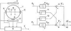
- FIG. 1is a schematic block diagram illustrating a magnetically inductive flowmeter in accordance with the invention.
- FIG. 2is a schematic block diagram illustrating the signal processing in accordance with the invention.
- a magnetically inductive flowmeterhas a measurement tube 1 , which extends at right angles to the plane of the drawing and through which a medium flows, of which the volume flow is to be detected.
- a magnetic field B of alternating polarityis created in the inside of the tube and thus in the flow medium, by virtue of a direct current of alternating polarity being fed into the coils 2 and 3 , for example.
- a measurement section DArranged on both sides of a measurement section D are measurement electrodes A and C and on the floor of the measurement tube 1 , for example, there is a reference electrode R, which serves as a reference potential electrode.
- the measurement electrodes A and Cdelimit the measurement section D, of which the length corresponds in the exemplary illustrated embodiment to the diameter of the measurement tube 1 .
- a voltageis induced in measurement section D, which is determined via the electrode arrangement, which comprises the measurement electrodes A and C and also the reference potential electrode R, and a control and evaluation device 4 .
- the control and evaluation device 4thus establishes the voltage induced over the measurement section D, calculates from this a measurement value for the flow and establishes diagnostic information about the state of the flowmeter.
- the results obtainedcan be passed on via a communications interface 5 to a higher-ranking control station in a process technology system.
- a first electrical voltage signal E Ais captured by the voltage between the electrode A ( FIG. 1 ) and a reference potential being tapped off.
- the potential tapped off at the reference electrode R ( FIG. 1 )preferably serves as the reference potential.
- a second voltage signal E Cis captured via the electrode C ( FIG. 1 ), which is arranged on the opposite side of the measurement section D, and the reference electrode R.
- the signal components caused by the electrochemical effects described aboveare filtered out of the first voltage signal E A and the second voltage signal E C with a notch filter 6 or 7 in each case, and in this way the first noise signal E NA and the second noise signal E NC obtained.
- the blocking frequency of the notch filter 6 and 7is tuned to the frequency of the polarity change of the magnetic field B ( FIG. 1 ).
- the first noise signal E NA and also the second noise signal E NCare thus freed from the signal components that stem from the flow.
- the first voltage signal E A and the second noise signal E NCare summed to create a first sum signal E′ A or the second voltage signal E C and the first noise signal E NA to create a second sum signal E′ C .
- suitable delay elements 11 or 12which advantageously cause the same delay, can be inserted into the respective parallel signal paths for compensation.
- an electromagnetic flowmeteris thus obtained, with which a long-term elimination of the noise caused by electrochemical reactions can be guaranteed. This furthermore results in a more stable measurement signal with lower susceptibility to noise and an improved signal-to-noise ratio, as well as ultimately to a higher measurement accuracy of the flowmeter.
Landscapes
- Physics & Mathematics (AREA)
- Electromagnetism (AREA)
- Fluid Mechanics (AREA)
- General Physics & Mathematics (AREA)
- Engineering & Computer Science (AREA)
- Power Engineering (AREA)
- Measuring Volume Flow (AREA)
Abstract
Description
EA=ESA+ENAand
EC=ESC+ENC. Eq. 1
E′A=ESA+ENA+ENCand
E′C=ESC+ENC+ENA. Eq. 2
ΔE′A,C=E′A−E′C=(ESA+ENA+ENC)−(ESC+ENC+ENA)=ESA−ESC. Eq. 3
Claims (6)
Applications Claiming Priority (3)
| Application Number | Priority Date | Filing Date | Title |
|---|---|---|---|
| DE102016211577.4 | 2016-06-28 | ||
| DE102016211577.4ADE102016211577A1 (en) | 2016-06-28 | 2016-06-28 | Magnetic-inductive flowmeter |
| PCT/EP2017/065991WO2018002135A1 (en) | 2016-06-28 | 2017-06-28 | Magnetically inductive flowmeter |
Publications (2)
| Publication Number | Publication Date |
|---|---|
| US20200166392A1 US20200166392A1 (en) | 2020-05-28 |
| US11067418B2true US11067418B2 (en) | 2021-07-20 |
Family
ID=59270019
Family Applications (1)
| Application Number | Title | Priority Date | Filing Date |
|---|---|---|---|
| US16/312,807Active2038-03-30US11067418B2 (en) | 2016-06-28 | 2017-06-28 | Magnetically inductive flowmeter for suppressing noise |
Country Status (5)
| Country | Link |
|---|---|
| US (1) | US11067418B2 (en) |
| EP (1) | EP3475665B1 (en) |
| CN (1) | CN109416268B (en) |
| DE (1) | DE102016211577A1 (en) |
| WO (1) | WO2018002135A1 (en) |
Families Citing this family (9)
| Publication number | Priority date | Publication date | Assignee | Title |
|---|---|---|---|---|
| DE102016211577A1 (en) | 2016-06-28 | 2017-12-28 | Siemens Aktiengesellschaft | Magnetic-inductive flowmeter |
| DE102017105547A1 (en)* | 2017-03-15 | 2018-09-20 | Krohne Ag | Method for determining the flow profile, transducer, electromagnetic flowmeter and use of a magnetic-inductive flowmeter |
| WO2020079085A1 (en)* | 2018-10-18 | 2020-04-23 | Eicon Gmbh | Magnetic flow meter |
| CN109974793B (en)* | 2019-04-22 | 2020-08-04 | 合肥工业大学 | Signal processing method for measuring flow of gas-containing conductive liquid by electromagnetic vortex shedding flowmeter |
| CN110464329B (en)* | 2019-07-19 | 2020-06-02 | 东北大学 | A method and device for measuring blood flow velocity distribution |
| US11131571B2 (en)* | 2019-07-22 | 2021-09-28 | Georg Fischer Signett LLC | Magnetic flowmeter assembly with glitch removing capability |
| US11092470B2 (en)* | 2019-09-13 | 2021-08-17 | Micro Motion Inc. | Magnetic flowmeter with noise adaptive dead time |
| DE102020123941A1 (en)* | 2020-09-15 | 2022-03-17 | Krohne Messtechnik Gmbh | Method for operating a magnetic-inductive flowmeter and corresponding magnetic-inductive flowmeter |
| CN114527334B (en)* | 2021-12-30 | 2025-03-04 | 江苏宜海新能源材料科技有限公司 | A device for measuring magnetic field strength based on potential difference method |
Citations (19)
| Publication number | Priority date | Publication date | Assignee | Title |
|---|---|---|---|---|
| DE2410407A1 (en) | 1974-03-05 | 1975-09-18 | Krohne Fa Ludwig | PROCEDURE FOR COMPENSATION OF THE ELECTROCHEMICAL INTERFERENCE VOLTAGE DURING INDUCTIVE FLOW MEASUREMENT WITH PERIODICALLY SWITCHED EQUAL FIELD |
| US4036052A (en) | 1976-07-30 | 1977-07-19 | Fischer & Porter Co. | Electromagnetic flowmeter usable in less-than-full fluid lines |
| US4644799A (en) | 1984-09-07 | 1987-02-24 | Kabushiki Kaisha Toshiba | Electromagnetic flow meter |
| US5388465A (en) | 1992-11-17 | 1995-02-14 | Yamatake-Honeywell Co., Ltd. | Electromagnetic flowmeter |
| EP1042651A1 (en) | 1997-12-24 | 2000-10-11 | ABB Kent-Taylor Limited | Electrode integrity checking |
| US6920799B1 (en) | 2004-04-15 | 2005-07-26 | Rosemount Inc. | Magnetic flow meter with reference electrode |
| US20070035309A1 (en)* | 2005-07-16 | 2007-02-15 | Dieter Keese | Method and device for detecting physical-chemical states on measuring electrodes of a flowmeter |
| CN101221057A (en) | 2008-01-18 | 2008-07-16 | 天津天仪集团仪表有限公司 | On-site bus electromagnetic flowmeter |
| US20080250866A1 (en)* | 2004-11-29 | 2008-10-16 | Endress + Hauser Flowtec Ag | Method For Monitoring Function of a Magneto-Inductive Flow Transducer |
| DE102007053222A1 (en) | 2007-11-06 | 2009-05-07 | Endress + Hauser Flowtec Ag | Apparatus and method for signal processing of voltage signals from electrodes of a magnetic inductive flowmeter |
| US20100192700A1 (en) | 2009-02-03 | 2010-08-05 | Kabushiki Kaisha Toshiba | Measurement apparatus |
| US20110239778A1 (en) | 2010-03-30 | 2011-10-06 | Yamatake Corporation | Electromagnetic flow meter |
| US20130238259A1 (en) | 2010-11-19 | 2013-09-12 | Azbil Corporation | Electromagnetic flow meter |
| CN103743443A (en) | 2013-11-08 | 2014-04-23 | 上海大学 | Method for detecting signal faults of electromagnetic flow meter |
| CN104061969A (en) | 2014-07-08 | 2014-09-24 | 电子科技大学 | Capacitive electromagnetic flow signal converter |
| US20150177035A1 (en)* | 2013-12-20 | 2015-06-25 | Rosemount Inc. | Magnetic flowmeter with automatic operating setpoint selection |
| US20160231152A1 (en)* | 2015-02-05 | 2016-08-11 | Invensys Systems, Inc. | Electromagnetic flowmeter and method of using same |
| WO2018002135A1 (en) | 2016-06-28 | 2018-01-04 | Siemens Aktiengesellschaft | Magnetically inductive flowmeter |
| US20190156600A1 (en)* | 2006-11-16 | 2019-05-23 | Ge Global Sourcing Llc | Locomotive sensor system for monitoring engine and lubricant health |
Family Cites Families (2)
| Publication number | Priority date | Publication date | Assignee | Title |
|---|---|---|---|---|
| US5555190A (en)* | 1995-07-12 | 1996-09-10 | Micro Motion, Inc. | Method and apparatus for adaptive line enhancement in Coriolis mass flow meter measurement |
| DE19716119C1 (en)* | 1997-04-17 | 1998-09-03 | Bailey Fischer & Porter Gmbh | Signal input circuit for magnetic inductive flowmeter with liquid flowing through measuring tube |
- 2016
- 2016-06-28DEDE102016211577.4Apatent/DE102016211577A1/ennot_activeWithdrawn
- 2017
- 2017-06-28WOPCT/EP2017/065991patent/WO2018002135A1/ennot_activeCeased
- 2017-06-28USUS16/312,807patent/US11067418B2/enactiveActive
- 2017-06-28CNCN201780040318.4Apatent/CN109416268B/enactiveActive
- 2017-06-28EPEP17734711.9Apatent/EP3475665B1/enactiveActive
Patent Citations (24)
| Publication number | Priority date | Publication date | Assignee | Title |
|---|---|---|---|---|
| DE2410407A1 (en) | 1974-03-05 | 1975-09-18 | Krohne Fa Ludwig | PROCEDURE FOR COMPENSATION OF THE ELECTROCHEMICAL INTERFERENCE VOLTAGE DURING INDUCTIVE FLOW MEASUREMENT WITH PERIODICALLY SWITCHED EQUAL FIELD |
| US4010644A (en) | 1974-03-05 | 1977-03-08 | Ludwig Krohne K.G. | Method for compensation of the electrochemical perturbing direct current potential in inductive flow measurement with a periodically switched uniform field |
| US4036052A (en) | 1976-07-30 | 1977-07-19 | Fischer & Porter Co. | Electromagnetic flowmeter usable in less-than-full fluid lines |
| US4644799A (en) | 1984-09-07 | 1987-02-24 | Kabushiki Kaisha Toshiba | Electromagnetic flow meter |
| US5388465A (en) | 1992-11-17 | 1995-02-14 | Yamatake-Honeywell Co., Ltd. | Electromagnetic flowmeter |
| EP1042651A1 (en) | 1997-12-24 | 2000-10-11 | ABB Kent-Taylor Limited | Electrode integrity checking |
| US6392416B1 (en) | 1997-12-24 | 2002-05-21 | Abb Kent Taylor Limited | Electrode integrity checking |
| GB2333161B (en) | 1997-12-24 | 2002-06-12 | Abb Kent Taylor Ltd | Electrode integrity checking |
| US6920799B1 (en) | 2004-04-15 | 2005-07-26 | Rosemount Inc. | Magnetic flow meter with reference electrode |
| WO2005106400A1 (en) | 2004-04-15 | 2005-11-10 | Rosemount Inc. | Magnetic flow meter with reference elctrode |
| US20080250866A1 (en)* | 2004-11-29 | 2008-10-16 | Endress + Hauser Flowtec Ag | Method For Monitoring Function of a Magneto-Inductive Flow Transducer |
| US20070035309A1 (en)* | 2005-07-16 | 2007-02-15 | Dieter Keese | Method and device for detecting physical-chemical states on measuring electrodes of a flowmeter |
| US20190156600A1 (en)* | 2006-11-16 | 2019-05-23 | Ge Global Sourcing Llc | Locomotive sensor system for monitoring engine and lubricant health |
| DE102007053222A1 (en) | 2007-11-06 | 2009-05-07 | Endress + Hauser Flowtec Ag | Apparatus and method for signal processing of voltage signals from electrodes of a magnetic inductive flowmeter |
| US20100231294A1 (en)* | 2007-11-06 | 2010-09-16 | Endress + Hauser Flowtec Ag | Apparatus and method for signal processing of voltage signals from electrodes of a magneto-inductive, flow measuring device bier3004/fjd |
| CN101221057A (en) | 2008-01-18 | 2008-07-16 | 天津天仪集团仪表有限公司 | On-site bus electromagnetic flowmeter |
| US20100192700A1 (en) | 2009-02-03 | 2010-08-05 | Kabushiki Kaisha Toshiba | Measurement apparatus |
| US20110239778A1 (en) | 2010-03-30 | 2011-10-06 | Yamatake Corporation | Electromagnetic flow meter |
| US20130238259A1 (en) | 2010-11-19 | 2013-09-12 | Azbil Corporation | Electromagnetic flow meter |
| CN103743443A (en) | 2013-11-08 | 2014-04-23 | 上海大学 | Method for detecting signal faults of electromagnetic flow meter |
| US20150177035A1 (en)* | 2013-12-20 | 2015-06-25 | Rosemount Inc. | Magnetic flowmeter with automatic operating setpoint selection |
| CN104061969A (en) | 2014-07-08 | 2014-09-24 | 电子科技大学 | Capacitive electromagnetic flow signal converter |
| US20160231152A1 (en)* | 2015-02-05 | 2016-08-11 | Invensys Systems, Inc. | Electromagnetic flowmeter and method of using same |
| WO2018002135A1 (en) | 2016-06-28 | 2018-01-04 | Siemens Aktiengesellschaft | Magnetically inductive flowmeter |
Non-Patent Citations (1)
| Title |
|---|
| PCT International Search Report based on PCT/EP2017/065991 dated Sep. 22, 2017. |
Also Published As
| Publication number | Publication date |
|---|---|
| EP3475665A1 (en) | 2019-05-01 |
| CN109416268A (en) | 2019-03-01 |
| US20200166392A1 (en) | 2020-05-28 |
| CN109416268B (en) | 2020-11-03 |
| WO2018002135A1 (en) | 2018-01-04 |
| DE102016211577A1 (en) | 2017-12-28 |
| EP3475665B1 (en) | 2023-12-27 |
| EP3475665C0 (en) | 2023-12-27 |
Similar Documents
| Publication | Publication Date | Title |
|---|---|---|
| US11067418B2 (en) | Magnetically inductive flowmeter for suppressing noise | |
| EP0416866B1 (en) | Electromagnetic flowmeter utilizing magnetic fields of a plurality of frequencies | |
| US7343817B2 (en) | Magnetic flow meter with unibody construction and conductive polymer electrodes | |
| US8408070B2 (en) | Electromagnetic flowmeter and method incorporating the same | |
| US7265544B2 (en) | Method and device for detecting physical-chemical states on measuring electrodes of a flowmeter | |
| EP2372317A1 (en) | Electromagnetic flow meter | |
| CN101424652A (en) | Method and device for measuring foreign bodies in the measuring medium | |
| US7117750B2 (en) | Method for operating a magnetoinductive flowmeter | |
| DE102015104217A1 (en) | Measuring system for determining the specific electrical conductivity | |
| EP1285236B1 (en) | Conduction indication in a magnetic flowmeter | |
| DE102014119512A1 (en) | Flowmeter | |
| CN105737727B (en) | Probe of eddy current sensor and eddy current sensor | |
| AU2011247656B2 (en) | Measuring device and method for measuring the flow rate of a medium flowing through a measuring tube | |
| CN105571662A (en) | Signal processing method and device for electromagnetic flowmeter | |
| Liu et al. | Research on the influence of different microchannel position on the sensitivity of inductive sensor | |
| US8857268B2 (en) | Method and electromagnetic flowmeter having corrosion protected measuring electrodes | |
| US20200309577A1 (en) | Magnetic Flowmeter with Enhanced Signal/Noise Ratio | |
| JP4860588B2 (en) | Ion concentration measuring device | |
| JP5854217B2 (en) | Electromagnetic flow meter | |
| US20240302193A1 (en) | Method for Operating a Magnetic-Inductive Flowmeter and Magnetic-Inductive Flowmeter | |
| JPS6383614A (en) | electromagnetic flow meter | |
| Maalouf | A validated model for the electromagnetic flowmeter's measuring cell: case of having an electrolytic conductor flowing through | |
| Velt et al. | Measuring the metal-containing mass of pulp products using the electromagnetic method | |
| JPH0886674A (en) | Capacity type electromagnetic flow meter | |
| Velt et al. | Electromagnetic Flowmeters With the Governing Boundary Conditions on The Channel Wall |
Legal Events
| Date | Code | Title | Description |
|---|---|---|---|
| FEPP | Fee payment procedure | Free format text:ENTITY STATUS SET TO UNDISCOUNTED (ORIGINAL EVENT CODE: BIG.); ENTITY STATUS OF PATENT OWNER: LARGE ENTITY | |
| STPP | Information on status: patent application and granting procedure in general | Free format text:RESPONSE TO NON-FINAL OFFICE ACTION ENTERED AND FORWARDED TO EXAMINER | |
| STPP | Information on status: patent application and granting procedure in general | Free format text:NOTICE OF ALLOWANCE MAILED -- APPLICATION RECEIVED IN OFFICE OF PUBLICATIONS | |
| STPP | Information on status: patent application and granting procedure in general | Free format text:NOTICE OF ALLOWANCE MAILED -- APPLICATION RECEIVED IN OFFICE OF PUBLICATIONS | |
| AS | Assignment | Owner name:SIEMENS A/S, DENMARK Free format text:ASSIGNMENT OF ASSIGNORS INTEREST;ASSIGNORS:ISIK-UPPENKAMP, SONNUR;MONDRUP, NIELS PER;SIGNING DATES FROM 20200226 TO 20210517;REEL/FRAME:056311/0296 Owner name:SIEMENS AKTIENGESELLSCHAFT, GERMANY Free format text:ASSIGNMENT OF ASSIGNORS INTEREST;ASSIGNOR:SIEMENS A/S;REEL/FRAME:056311/0310 Effective date:20210519 | |
| STPP | Information on status: patent application and granting procedure in general | Free format text:PUBLICATIONS -- ISSUE FEE PAYMENT RECEIVED | |
| STPP | Information on status: patent application and granting procedure in general | Free format text:PUBLICATIONS -- ISSUE FEE PAYMENT VERIFIED | |
| STCF | Information on status: patent grant | Free format text:PATENTED CASE | |
| MAFP | Maintenance fee payment | Free format text:PAYMENT OF MAINTENANCE FEE, 4TH YEAR, LARGE ENTITY (ORIGINAL EVENT CODE: M1551); ENTITY STATUS OF PATENT OWNER: LARGE ENTITY Year of fee payment:4 |