US11066159B2 - EVTOL aircraft using large, variable speed tilt rotors - Google Patents
EVTOL aircraft using large, variable speed tilt rotorsDownload PDFInfo
- Publication number
- US11066159B2 US11066159B2US16/155,669US201816155669AUS11066159B2US 11066159 B2US11066159 B2US 11066159B2US 201816155669 AUS201816155669 AUS 201816155669AUS 11066159 B2US11066159 B2US 11066159B2
- Authority
- US
- United States
- Prior art keywords
- rotors
- design
- aircraft
- engineering
- rotor
- Prior art date
- Legal status (The legal status is an assumption and is not a legal conclusion. Google has not performed a legal analysis and makes no representation as to the accuracy of the status listed.)
- Active, expires
Links
- 238000000034methodMethods0.000claimsabstractdescription31
- 238000013461designMethods0.000claimsdescription42
- 230000007704transitionEffects0.000claimsdescription13
- 230000002459sustained effectEffects0.000claimsdescription6
- 210000003746featherAnatomy0.000description12
- 230000008901benefitEffects0.000description9
- 238000001816coolingMethods0.000description8
- 238000005452bendingMethods0.000description7
- 230000006870functionEffects0.000description6
- 230000009467reductionEffects0.000description6
- 239000012530fluidSubstances0.000description5
- 230000003068static effectEffects0.000description5
- 239000013585weight reducing agentSubstances0.000description5
- 238000004458analytical methodMethods0.000description4
- 238000009434installationMethods0.000description4
- 241000272517AnseriformesSpecies0.000description3
- 238000013459approachMethods0.000description3
- 230000008878couplingEffects0.000description3
- 238000010168coupling processMethods0.000description3
- 238000005859coupling reactionMethods0.000description3
- 238000009826distributionMethods0.000description3
- 230000000694effectsEffects0.000description3
- 230000005284excitationEffects0.000description3
- 238000005457optimizationMethods0.000description3
- 230000004044responseEffects0.000description3
- 238000000926separation methodMethods0.000description3
- LYCAIKOWRPUZTN-UHFFFAOYSA-NEthylene glycolChemical compoundOCCOLYCAIKOWRPUZTN-UHFFFAOYSA-N0.000description2
- 238000006243chemical reactionMethods0.000description2
- 230000007423decreaseEffects0.000description2
- 238000011161developmentMethods0.000description2
- 238000005516engineering processMethods0.000description2
- 238000012986modificationMethods0.000description2
- 230000004048modificationEffects0.000description2
- 238000011084recoveryMethods0.000description2
- RZVHIXYEVGDQDX-UHFFFAOYSA-N9,10-anthraquinoneChemical compoundC1=CC=C2C(=O)C3=CC=CC=C3C(=O)C2=C1RZVHIXYEVGDQDX-UHFFFAOYSA-N0.000description1
- 230000004308accommodationEffects0.000description1
- 230000004075alterationEffects0.000description1
- 230000000712assemblyEffects0.000description1
- 238000000429assemblyMethods0.000description1
- 238000002485combustion reactionMethods0.000description1
- 230000000295complement effectEffects0.000description1
- 239000002131composite materialSubstances0.000description1
- 238000010276constructionMethods0.000description1
- 239000002826coolantSubstances0.000description1
- 238000012217deletionMethods0.000description1
- 230000037430deletionEffects0.000description1
- 230000005611electricityEffects0.000description1
- 230000010006flightEffects0.000description1
- 210000004907glandAnatomy0.000description1
- 230000017525heat dissipationEffects0.000description1
- WGCNASOHLSPBMP-UHFFFAOYSA-NhydroxyacetaldehydeNatural productsOCC=OWGCNASOHLSPBMP-UHFFFAOYSA-N0.000description1
- 239000004615ingredientSubstances0.000description1
- 239000007788liquidSubstances0.000description1
- 229910001416lithium ionInorganic materials0.000description1
- 230000033001locomotionEffects0.000description1
- 238000012423maintenanceMethods0.000description1
- 230000014759maintenance of locationEffects0.000description1
- 239000000463materialSubstances0.000description1
- 239000011159matrix materialSubstances0.000description1
- 238000005259measurementMethods0.000description1
- 239000002184metalSubstances0.000description1
- 229920000642polymerPolymers0.000description1
- 230000036316preloadEffects0.000description1
- 230000000717retained effectEffects0.000description1
- 238000005096rolling processMethods0.000description1
- 238000004088simulationMethods0.000description1
- 238000004513sizingMethods0.000description1
- 238000012916structural analysisMethods0.000description1
- 239000000126substanceSubstances0.000description1
- 238000012360testing methodMethods0.000description1
- 238000012549trainingMethods0.000description1
- 238000012546transferMethods0.000description1
- XLYOFNOQVPJJNP-UHFFFAOYSA-NwaterSubstancesOXLYOFNOQVPJJNP-UHFFFAOYSA-N0.000description1
- 238000004804windingMethods0.000description1
Images


Classifications
- B—PERFORMING OPERATIONS; TRANSPORTING
- B64—AIRCRAFT; AVIATION; COSMONAUTICS
- B64C—AEROPLANES; HELICOPTERS
- B64C11/00—Propellers, e.g. of ducted type; Features common to propellers and rotors for rotorcraft
- B64C11/30—Blade pitch-changing mechanisms
- B64C11/44—Blade pitch-changing mechanisms electric
- B—PERFORMING OPERATIONS; TRANSPORTING
- B64—AIRCRAFT; AVIATION; COSMONAUTICS
- B64C—AEROPLANES; HELICOPTERS
- B64C29/00—Aircraft capable of landing or taking-off vertically, e.g. vertical take-off and landing [VTOL] aircraft
- B64C29/0008—Aircraft capable of landing or taking-off vertically, e.g. vertical take-off and landing [VTOL] aircraft having its flight directional axis horizontal when grounded
- B64C29/0016—Aircraft capable of landing or taking-off vertically, e.g. vertical take-off and landing [VTOL] aircraft having its flight directional axis horizontal when grounded the lift during taking-off being created by free or ducted propellers or by blowers
- B64C29/0033—Aircraft capable of landing or taking-off vertically, e.g. vertical take-off and landing [VTOL] aircraft having its flight directional axis horizontal when grounded the lift during taking-off being created by free or ducted propellers or by blowers the propellers being tiltable relative to the fuselage
- B—PERFORMING OPERATIONS; TRANSPORTING
- B64—AIRCRAFT; AVIATION; COSMONAUTICS
- B64C—AEROPLANES; HELICOPTERS
- B64C11/00—Propellers, e.g. of ducted type; Features common to propellers and rotors for rotorcraft
- B64C11/30—Blade pitch-changing mechanisms
- B64C11/32—Blade pitch-changing mechanisms mechanical
- B64C11/325—Blade pitch-changing mechanisms mechanical comprising feathering, braking or stopping systems
- B—PERFORMING OPERATIONS; TRANSPORTING
- B64—AIRCRAFT; AVIATION; COSMONAUTICS
- B64C—AEROPLANES; HELICOPTERS
- B64C13/00—Control systems or transmitting systems for actuating flying-control surfaces, lift-increasing flaps, air brakes, or spoilers
- B64C13/02—Initiating means
- B64C13/16—Initiating means actuated automatically, e.g. responsive to gust detectors
- B64C13/18—Initiating means actuated automatically, e.g. responsive to gust detectors using automatic pilot
- B—PERFORMING OPERATIONS; TRANSPORTING
- B64—AIRCRAFT; AVIATION; COSMONAUTICS
- B64C—AEROPLANES; HELICOPTERS
- B64C27/00—Rotorcraft; Rotors peculiar thereto
- B64C27/22—Compound rotorcraft, i.e. aircraft using in flight the features of both aeroplane and rotorcraft
- B64C27/28—Compound rotorcraft, i.e. aircraft using in flight the features of both aeroplane and rotorcraft with forward-propulsion propellers pivotable to act as lifting rotors
- B—PERFORMING OPERATIONS; TRANSPORTING
- B64—AIRCRAFT; AVIATION; COSMONAUTICS
- B64C—AEROPLANES; HELICOPTERS
- B64C3/00—Wings
- B64C3/10—Shape of wings
- B—PERFORMING OPERATIONS; TRANSPORTING
- B64—AIRCRAFT; AVIATION; COSMONAUTICS
- B64C—AEROPLANES; HELICOPTERS
- B64C3/00—Wings
- B64C3/10—Shape of wings
- B64C3/16—Frontal aspect
- B—PERFORMING OPERATIONS; TRANSPORTING
- B64—AIRCRAFT; AVIATION; COSMONAUTICS
- B64C—AEROPLANES; HELICOPTERS
- B64C39/00—Aircraft not otherwise provided for
- B64C39/12—Canard-type aircraft
- B—PERFORMING OPERATIONS; TRANSPORTING
- B64—AIRCRAFT; AVIATION; COSMONAUTICS
- B64C—AEROPLANES; HELICOPTERS
- B64C5/00—Stabilising surfaces
- B64C5/02—Tailplanes
- B—PERFORMING OPERATIONS; TRANSPORTING
- B64—AIRCRAFT; AVIATION; COSMONAUTICS
- B64C—AEROPLANES; HELICOPTERS
- B64C9/00—Adjustable control surfaces or members, e.g. rudders
- B64C9/14—Adjustable control surfaces or members, e.g. rudders forming slots
- B64C9/16—Adjustable control surfaces or members, e.g. rudders forming slots at the rear of the wing
- B64C9/18—Adjustable control surfaces or members, e.g. rudders forming slots at the rear of the wing by single flaps
- B—PERFORMING OPERATIONS; TRANSPORTING
- B64—AIRCRAFT; AVIATION; COSMONAUTICS
- B64D—EQUIPMENT FOR FITTING IN OR TO AIRCRAFT; FLIGHT SUITS; PARACHUTES; ARRANGEMENT OR MOUNTING OF POWER PLANTS OR PROPULSION TRANSMISSIONS IN AIRCRAFT
- B64D27/00—Arrangement or mounting of power plants in aircraft; Aircraft characterised by the type or position of power plants
- B64D27/02—Aircraft characterised by the type or position of power plants
- B64D27/24—Aircraft characterised by the type or position of power plants using steam or spring force
- B—PERFORMING OPERATIONS; TRANSPORTING
- B64—AIRCRAFT; AVIATION; COSMONAUTICS
- B64D—EQUIPMENT FOR FITTING IN OR TO AIRCRAFT; FLIGHT SUITS; PARACHUTES; ARRANGEMENT OR MOUNTING OF POWER PLANTS OR PROPULSION TRANSMISSIONS IN AIRCRAFT
- B64D27/00—Arrangement or mounting of power plants in aircraft; Aircraft characterised by the type or position of power plants
- B64D27/02—Aircraft characterised by the type or position of power plants
- B64D27/30—Aircraft characterised by electric power plants
- B64D27/34—All-electric aircraft
- B—PERFORMING OPERATIONS; TRANSPORTING
- B64—AIRCRAFT; AVIATION; COSMONAUTICS
- B64D—EQUIPMENT FOR FITTING IN OR TO AIRCRAFT; FLIGHT SUITS; PARACHUTES; ARRANGEMENT OR MOUNTING OF POWER PLANTS OR PROPULSION TRANSMISSIONS IN AIRCRAFT
- B64D35/00—Transmitting power from power plants to propellers or rotors; Arrangements of transmissions
- B64D35/02—Transmitting power from power plants to propellers or rotors; Arrangements of transmissions specially adapted for specific power plants
- B64D35/021—Transmitting power from power plants to propellers or rotors; Arrangements of transmissions specially adapted for specific power plants for electric power plants
- B—PERFORMING OPERATIONS; TRANSPORTING
- B64—AIRCRAFT; AVIATION; COSMONAUTICS
- B64F—GROUND OR AIRCRAFT-CARRIER-DECK INSTALLATIONS SPECIALLY ADAPTED FOR USE IN CONNECTION WITH AIRCRAFT; DESIGNING, MANUFACTURING, ASSEMBLING, CLEANING, MAINTAINING OR REPAIRING AIRCRAFT, NOT OTHERWISE PROVIDED FOR; HANDLING, TRANSPORTING, TESTING OR INSPECTING AIRCRAFT COMPONENTS, NOT OTHERWISE PROVIDED FOR
- B64F5/00—Designing, manufacturing, assembling, cleaning, maintaining or repairing aircraft, not otherwise provided for; Handling, transporting, testing or inspecting aircraft components, not otherwise provided for
- Y—GENERAL TAGGING OF NEW TECHNOLOGICAL DEVELOPMENTS; GENERAL TAGGING OF CROSS-SECTIONAL TECHNOLOGIES SPANNING OVER SEVERAL SECTIONS OF THE IPC; TECHNICAL SUBJECTS COVERED BY FORMER USPC CROSS-REFERENCE ART COLLECTIONS [XRACs] AND DIGESTS
- Y02—TECHNOLOGIES OR APPLICATIONS FOR MITIGATION OR ADAPTATION AGAINST CLIMATE CHANGE
- Y02T—CLIMATE CHANGE MITIGATION TECHNOLOGIES RELATED TO TRANSPORTATION
- Y02T50/00—Aeronautics or air transport
- Y02T50/40—Weight reduction
- Y—GENERAL TAGGING OF NEW TECHNOLOGICAL DEVELOPMENTS; GENERAL TAGGING OF CROSS-SECTIONAL TECHNOLOGIES SPANNING OVER SEVERAL SECTIONS OF THE IPC; TECHNICAL SUBJECTS COVERED BY FORMER USPC CROSS-REFERENCE ART COLLECTIONS [XRACs] AND DIGESTS
- Y02—TECHNOLOGIES OR APPLICATIONS FOR MITIGATION OR ADAPTATION AGAINST CLIMATE CHANGE
- Y02T—CLIMATE CHANGE MITIGATION TECHNOLOGIES RELATED TO TRANSPORTATION
- Y02T50/00—Aeronautics or air transport
- Y02T50/60—Efficient propulsion technologies, e.g. for aircraft
Definitions
- the field of the inventionis vertical take-off and landing aircraft.
- FIG. 1Ais a conceptual image of an upcoming urban transportation market for Uber®'s proposed hybrid-electric vertical takeoff and landing (eVTOL) aircraft.
- FIG. 1Bis a projected schedule of development and operations for such aircraft.
- FIGS. 2A and 2Bare artist's renditions of a prior art 16-rotor VolocopterTM
- FIG. 3is a photograph of a prior art 8-rotor EhangTM
- FIG. 4is a photograph of a prior art 8-rotor CityAirbusTM. All these designs are, however, problematic because the rotors do not tilt from vertical lift to forward propulsion positions, and there are no wings. That combination is extremely inefficient in forward flight, which limits the aircraft to relatively short ranges.
- FIG. 5is an artist's rendition of a prior art 36-rotor LiliumTM eVTOL, in which the rotors tilt about the forward and aft wings.
- the manufacturerclaims a 300 km range, and 300 km/hr speed.
- This aircraftis, however, still problematic because the high disc loading results in low power loading (high installed power per weight), which reduces efficiency and range, and produces high noise levels.
- FIG. 6is an artist's rendition of an 8-rotor AirbusTM A3 Vahana. This aircraft is problematic because it trades off higher efficiency in forward flight for very high power requirements during transition from vertical lift to forward flight. In such transition, the wings act as huge airbrakes.
- FIG. 7is an image of a Computational Fluid Dynamics (CFD) flow solution for the JobyTM 6-rotor eVTOL concept.
- CFDComputational Fluid Dynamics
- FIG. 8is an artist's rendition of the AuroraTM eVTOL concept, which uses eight lifting rotors and an aft facing propeller.
- This designis problematic because the duplicate propulsion systems require heavier and more expensive hardware, have marginal climb rate in wing borne cruise due to sizing the cruise powerplant for level cruise, and potentially have a smaller wingborne stall speed margin—gust entry and recovery, due to design optimization for higher cruise lift coefficient (smaller wing).
- Example: if flying at 130 mph, a vertical gust of 20 Ft/sec will increase the angle of attack by 6 degrees, may stall a small wing at its efficient lift coefficient of 0.9, but not stall a bigger wing at CL0.5.
- FIGS. 9A and 9Bshow artists' conceptions of a similar design, the TerrafugiaTM eVTOL. This design has the drawbacks mentioned above with respect to duplicate propulsion systems, and in addition, the twin tilt rotor configuration does not provide a method for pitch control in rotor borne flight.
- FIG. 10shows the motor installation of the AirbusTM A3 VahanaTM.
- the motoris arranged in a direct-drive configuration where motor and propeller spin at the same rotational speed. This simple propulsion system solution is problematic for large rotors with large torque requirements.
- the numbers expressing quantities of ingredients, properties such as concentration, reaction conditions, and so forth, used to describe and claim certain embodiments of the inventionare to be understood as being modified in some instances by the term “about.” Accordingly, in some embodiments, the numerical parameters set forth in the written description and attached claims are approximations that can vary depending upon the desired properties sought to be obtained by a particular embodiment. In some embodiments, the numerical parameters should be construed in light of the number of reported significant digits and by applying ordinary rounding techniques. Notwithstanding that the numerical ranges and parameters setting forth the broad scope of some embodiments of the invention are approximations, the numerical values set forth in the specific examples are reported as precisely as practicable. The numerical values presented in some embodiments of the invention may contain certain errors necessarily resulting from the standard deviation found in their respective testing measurements.
- Coupled tois intended to include both direct coupling (in which two elements that are coupled to each other contact each other) and indirect coupling (in which at least one additional element is located between the two elements). Therefore, the terms “coupled to” and “coupled with” are used synonymously.
- inventive subject matteris considered to include all possible combinations of the disclosed elements.
- inventive subject matteris also considered to include other remaining combinations of A, B, C, or D, even if not explicitly disclosed.
- inventive subject matterprovides apparatus, systems and methods in which an electric vertical takeoff and landing (eVTOL) aircraft is engineered to carry at least 500 pounds (approx. 227 kg) using a reduced number (e.g., 2-4) of variable speed rigid (non-articulated) rotors.
- eVTOLelectric vertical takeoff and landing
- FIG. 1Ais a prior art conceptual image of an upcoming urban transportation market for Uber®'s proposed hybrid-electric vertical takeoff and landing (eVTOL) aircraft.
- eVTOLhybrid-electric vertical takeoff and landing
- FIG. 1Bis a prior art projected schedule of development and operations for an aircraft according to FIG. 1A .
- FIGS. 2A and 2Bare artist's renditions of a prior art 16-rotor VolocopterTM.
- FIG. 3is an artist's rendition of a prior art 8-rotor EhangTM.
- FIG. 4is an artist's rendition of a prior art 8-rotor CityAirbusTM.
- FIG. 5is an artist's rendition of a prior art 36-rotor LiliumTM eVTOL, in which the rotors tilt about the forward and aft wings.
- FIG. 6which is an artist's rendition of a prior art, 8-rotor AirbusTM A3 VahanaTM.
- FIG. 7is an image of a Computational Fluid Dynamics (CFD) flow solution for the prior art JobyTM 6-rotor eVTOL concept aircraft.
- CFDComputational Fluid Dynamics
- FIG. 8is a prior art artist's rendition of the AuroraTM eVTOL concept aircraft, which uses eight lifting rotors and an aft facing propeller.
- FIGS. 9A and 9Bshow prior art artists' conceptions of a TerrafugiaTM eVTOL aircraft.
- FIG. 10shows the motor installation of the prior art AirbusTM A3 VahanaTM.
- FIG. 11is a schematic perspective view of a preferred VTOL aircraft according to the inventive concepts herein.
- FIG. 12is a table of dimensions and parameters of the aircraft of FIG. 11 .
- FIGS. 13A and 13Bare schematic top and side views, respectively, dimensioned drawings of the aircraft of FIG. 11 .
- FIG. 13Cis a table describing possible seating arrangements and calculated weights of the aircraft of FIG. 11 .
- FIGS. 13D and 13Eare schematic perspective views of the aircraft of FIG. 11 , with doors and hatches open.
- FIG. 13Fis a schematic side view of an open aft ramp of the aircraft of FIG. 11 .
- FIG. 13Gis a schematic view of a side section of the aircraft of FIG. 11 .
- FIG. 14is a schematic side view of a slotted flap that can be used with the aircraft of FIG. 11 , depicted in four different positions.
- FIG. 15Ais a schematic perspective view of an outboard wing fold feature that can be used with the aircraft of FIG. 11 .
- FIG. 15Bis a schematic front view of the outboard wing of FIG. 15A , in a folded orientation in the aircraft of FIG. 11 .
- FIG. 15Cis a schematic top view of the aircraft of FIG. 11 , with the outboard wing in a folded orientation, such that the aircraft fits in a 45′ diameter projected circular parking space.
- FIG. 16Ais a table describing calculated rotor geometry and properties as functions of non-dimensional radial station of the aircraft of FIG. 11 .
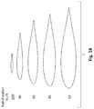
- FIGS. 16B-16Fare graphs depicting calculated beam flapwise bending stiffness, chordwise bending stiffness, torsional stiffness, mass per unit length, and cg position relative to the blade pitch axis, of the proposed rotor blades of the aircraft of FIG. 11 .
- FIG. 17is a graph depicting calculated lowest blade natural frequencies at a collective control setting of zero degrees as a function of rotor speed, of the aircraft of FIG. 11 .
- FIG. 18are schematics of five cross-sectional airfoil profiles of the rotor blades at specified radial stations, of the aircraft of FIG. 11 .
- FIG. 19Ais a first schematic perspective view of the drive system that can be used with the aircraft of FIG. 11 , enclosed in a streamlined nacelle, in position required for wing-borne flight.
- FIG. 19Bis a second schematic perspective view of a portion of the drive system that can be used with the aircraft of FIG. 11 .
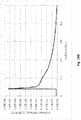
- FIG. 20is a graph depicting calculated effects of motor speed on motor weight, for the aircraft of FIG. 11 .
- FIG. 21Ais a schematic of a vertical cross-section of a preferred individual blade control (IBC) configuration, which can be used with the aircraft of FIG. 11 .
- IBCindividual blade control
- FIG. 21Bis a schematic of a vertical cross-section of an alternative preferred individual blade control (IBC) configuration, which can be used with the aircraft of FIG. 11 .
- IBCindividual blade control
- FIG. 22is a schematic perspective view of the aircraft of FIG. 11 , having individual blade control (IBC) actuators according to FIGS. 21A or 21B , having four-blade primary and four-blade secondary rotors.
- IBCblade control
- FIG. 23Ais a schematic cross sectional view of a nacelle that can be used with the aircraft of FIG. 11 , in which a battery is disposed below the wing, and internal to the nacelle.
- FIG. 23Bis a schematic cross sectional view of a nacelle and wing that can be used with the aircraft of FIG. 11 , in which a battery is disposed within the wing.
- FIGS. 24A-24Gare schematic perspective views of an alternative preferred VTOL aircraft according to the inventive concepts herein. This version has no secondary rotors.
- FIG. 25A and 25Bare schematic vertical cross-sectional views of the alternative VTOL aircraft of FIGS. 24A-24G , depicting a 3-row seating comparable to that of the 4-rotor configuration of FIG. 13G
- FIG. 26is a table of dimensions and parameters of the 2-rotor alternative VTOL aircraft of FIGS. 24A-24G .
- the inventive subject matterprovides apparatus, systems and methods in which an electric powered vertical takeoff and landing (eVTOL) aircraft is engineered to carry at least 500 pounds (approx. 227 kg) using a reduced number (2-4) of variable speed rigid (non-articulated) rotors, generally assembled as primary and secondary rotors.
- the rotorswhether primary or secondary, are preferably tilt rotors such that one or more of the rotors provides a significant amount of lift (e.g., 70%, etc) during rotor borne flight (e.g., vertical takeoff, etc), and can be tilted to provide forward thrust (or air braking) during wingborne flight.
- each rotorcan be powered by its own electric motor or motors, and in other contemplated embodiments, multiple rotors can be powered by a single electric motor. In especially preferred embodiments, individual rotors can be powered by three electric motors. It is also contemplated that different electric motors could be powered by different battery packs, or multiple electric motors could be powered by a single battery pack.
- batteryand “battery pack” are used interchangeably herein to refer to one or multiple chemical cells that produce electricity. Batteries preferably utilize Li-ion chemistries, and have a specific energy density of about 100 kWh/lb. Other contemplated battery chemistries include Li-Polymer and Li-Metal.
- Non-articulated rotorsare preferred because alteration of individual blade angles can be used to apply force moments to control pitch of the aircraft in both VTOL and wingborne cruise flight.
- Blade angle controlis preferably achieved by individual blade control actuators preferably fit inside their respective blades, fitted axially to the pitch axis.
- the individual blade control system utilized on at least each of the first and second primary rotorsimparts a differential collective pitch between blades on the rotor, such that rotor thrust is maintained approximately constant, while shaft torque is increased above the torque required without differential collective.
- the aircrafthas primary and secondary rotors.
- the primary rotorscomprise blades and hubs configured to provide for force moments at least equal to the rotor maximum lift times 6% of rotor radius, more preferably at least 9% of rotor radius, and most preferably at least 12% of rotor radius
- each of the primary rotorsis configured to provide a disc loading lower than 10 psf, and hover power loading higher than 8 lb/HP. More preferably, each of the primary rotors is configured to provide a disc loading lower than 6 psf, and hover power loading higher than 10 lb/HP. Other contemplated aircraft embodiments have less than 8 lb/HP power loading.
- contemplated embodimentsutilize rotor designs disclosed in U.S. Pat. No. 6,007,298 (Karem) “Optimum Speed Rotor” (OSR) and U.S. Pat. No. 6,641,365 (Karem) “Optimum Speed Tilt Rotor” (OSTR).
- aircraft contemplated hereinpreferably achieve flap stiffness of each blade that is not less than the product of 100, or even more preferably 200, times the rotor diameter in feet to the fourth power, as measured in lbs-in2, at 30% of the rotor radius as measured from a center of rotor rotation.
- each blade weight in lbspreferably does not exceed the product of 0.004 times the diameter of the rotor in feet cubed.
- Embodiments having first and second primary rotorsare contemplated to include at least one optional first auxiliary rotor, each of which has no greater than 50% of the disc area of each of the primary rotors.
- each of the auxiliary rotorshas no greater than 40% of the disc area of each of the primary rotors.
- Auxiliary rotorsneed not be the same size as each other.
- the auxiliary rotor or rotorsis/are also preferably rigid (no-articulated) rotors, which are configured to produce pitch force moments by altering the pitch of individual blades.
- At least the first auxiliary rotoris advantageously configured to provide a maximum aircraft pitch force moment that is no greater than the collective total aircraft pitch force moment capability of the primary rotors.
- the rotating hub, the corresponding hub bearing, gearbox, and motor mounting fixtureare all configured together as an integrated rotor drive system.
- the preferred embodimentincludes three independently controlled motors connected to a single gearbox per primary rotor.
- the three independently controlled motorsprovide a safety benefit through redundancy, and additionally that configuration has been found to be a lightweight solution for the high torque output required by a variable speed rotor.
- Preferred embodimentsinclude a wing that carries at least first and second of the rotors, each of which is disposed in a rotor assembly configured to tilt at least 90° relative to the wing.
- corresponding motors or other powerplantsare configured to tilt along with rotor assemblies.
- At least the primary rotorsare open, i.e., as the rotors tilt they are not bounded circumferentially by an air-directing band.
- the wingis relatively large relative to the weight of the aircraft and the payload. It is preferred, for example, that the wing is sized and dimensioned to provide for wing loading no higher than 40 psf, and for wingborne stall speed no higher than 90 KIAS. Especially preferred wings are further configured to provide for wing loading no higher than 20 psf, and for wingborne stall speed no higher than 50 KIAS. Preferred wings are further configured to provide a flight speed margin of no less than 20 KIAS in transition from fully rotor borne level flight to fully wing borne level flight, and wingborne cruise lift/drag ratio of no less than 10. Especially preferred wings are further configured to provide a transition flight speed margin of no less than 40 KIAS.
- the preferred wingis fitted with an actuated slotted flap.
- the flapcan be used to provide aircraft roll control.
- the wingis preferably configured with wing tip sections having a control system, and electric or other actuators that adjust the wing tips to an anhedral angle of between 20-90 degrees to: (a) provide for reduced wing down load in hover; (b) provide for roll support in taxi at cross wind; and (c) provide for aircraft tie down.
- the wing, rotors and other components and features discussed hereinare preferably engineered such that the aircraft can maneuver at 3 g at maximum weight without loss of altitude or speed, but still providing the aircraft with a low sustained autorotation descent rate if a motor fails.
- the preferred embodimenthas a sustained autorotation descent rate of less than 1,000 ft/min.
- At least a first battery or other power sourceis disposed in the wing.
- a landing gearextends from at least one of the fuselage and the wing.
- At least a first battery or other power sourceis disposed in a primary rotor nacelle.
- Embodimentsare contemplated that have a tail and/or a canard, each of which preferably has a lifting surface having an area between 10%-100% that of the wing.
- Contemplated embodimentsinclude both manned and unmanned aircraft.
- a fuselageis present, it can have a passenger compartment with at least one seat configured to seat a human.
- Electronic controlsare also contemplated, sufficient to fly the aircraft without an onboard human pilot.
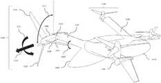
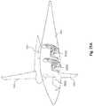
- FIG. 11is a perspective view of a preferred VTOL aircraft according to the inventive concepts herein.
- the aircrafthas a wing 1101 , static nacelle 1102 , tilting nacelle 1103 , fuselage 1150 , tail surface 1130 , and first tilting rotor system 1110 .
- An especially preferred embodimentincludes a first tilting auxiliary rotor system 1140 .
- Rotor system 1110includes rotor blades 1120 .
- the rotor bladesare of a stiff hingeless variety, including for example that described in U.S. Pat. No. 6,641,365 (Karem).
- the rotor systemcollectively provides thrust as indicated by arrow 1113 and force moment 1114 .
- the moments and forcescan be controlled by rotating the blades about a feather axis 1121 running the length of the blade 1120 .
- the pitch angle around the feather axis 1121is represented by arrow 1122 .
- the tip of the rotor bladefollows a rotational trajectory represented by a circle 1116 .
- the rotor blades 1120 and tilting nacelle 1103can tilt along the path represented by arrow 1111 about the tilt axis 1112 .
- the right-hand nacelleis in wingborne flight orientation while the left-hand nacelle is in rotor borne flight orientation.
- the nacelleswould be in similar orientations during typical operation.
- Wing 1101transmits loads from the rotor system to the fuselage 1150 .
- Fuselage 1150is designed to carry payload and passengers and contain various systems including a landing gear.
- FIG. 12is a table of dimensions and parameters of a preferred embodiment, with “*” denoting turbulent flow.
- the preferred embodiment described by the tableis designed for a nominal payload of approximately 1,100 lbs and Basic Mission Takeoff Weight of 4,767 lbs.
- a wing area of 250 sq. ft.produces a wing loading of 19.1 psf.
- a total disc area of 849 sq. ft.gives a hover disc loading of 6.62 lb/ft2 when including the effects of rotor wash on the airframe.
- FIGS. 13A and 13Bshow top and side views, respectively, dimensioned drawings of the preferred embodiment consistent with the aircraft represented in FIG. 11 .
- 1310is a main landing gear wheel attached to the fuselage 1150 .
- 1311is a nose landing gear wheel attached to the fuselage 1150 . All elements numbered previously are as described above.
- FIG. 13Bis a side view section showing the 2 upward opening nose hatches 1312 , car-like 4 doors, 1313 and 1314 , and baggage compartment 1315 of the preferred embodiment aircraft with 3 possible configurations: a) Air Taxi with one pilot and 4 passengers, b) Family Use with up to 8 passengers, and c) Cargo/Ambulance Use with folding aft row seats and optional ramp replacing the baggage compartment.
- the Family Use configurationwith 1,350 Lb payload capacity, is aimed at accommodating a family in a similar manner to that of a big SUV, except that the aircraft with the 2 nose hatches provides the equivalent of 6 doors as compared to the 4 doors of the SUV.
- FIG. 13Cis a table describing the preferred aircraft's seating arrangement and calculated weights.
- C.G. shiftloading vector
- Providing aircraft stability and control with such a wide C.G. shiftis made possible in rotor borne flight by the powerful pitch control combination of the preferred embodiment auxiliary rotors and the pitch moment of the rigid primary rotors, and in wingborne flight by the powerful pitch control combination of the large tail elevators and the pitch moment of the rigid primary rotors.
- FIGS. 13D and 13Eshow views of the preferred embodiment aircraft with doors and hatches open.
- FIG. 13Fshows the aft ramp 1316 open.
- Nose gear 1311optionally has variable height, allowing adjustment of the fuselage to ground angle, providing additional clearance at the ramp opening.
- FIG. 13Gshows a side view section of the fuselage with a proposed seating arrangement consistent with FIG. 13C .
- Electronics 1317capable of flying the aircraft without an onboard human pilot are envisioned for future operations.
- Aircraft contemplated hereinare designed for efficient vertical and cruise flight. Additionally, such aircraft are designed provide a safe flight and to be well-behaved in the intermediate flight condition between fully wingborne and rotorborne flight known as “transition.”
- Rotor thrust required for vertical flightis on the order of 10 ⁇ that required for efficient cruise flight.
- the preferred embodiment aircraftuses the variable speed rotor described in U.S. Pat. No. 6,641,365 (Karem) to achieve high efficiency from 100 RPM in low speed wingborne flight to 460 RPM in hover at 12,000 feet.
- the rotor aerodynamic designrepresents the relatively minor compromise of optimal characteristics for hover vs cruise flight typical with the 5:1 RPM range available with such rotor.
- a combination of airfoil designswhich have linear lift characteristics across a wide range of angle of attack and twist and chord distributions which balance vertical and cruise flight conditions are required.
- Sectional airfoil design and analysis toolssuch as XFOIL can be used to design and investigate airfoils which achieve the desired characteristics.
- Rotor analysis software for cruise such as XROTOR and software for hover rotor performance such as CHARM (CDI)can be used to optimize the rotor geometry for desired performance characteristics.
- the resulting preferred rotor geometryis given as a table in FIG. 16A and airfoil sections in FIG. 18 .
- a high lift-to-drag ratio of at least 10is desired.
- the drag of the fuselage and the nacelleare minimized by using computational fluid dynamics (CFD) programs, for example STAR-CCM+, to analyze and iteratively optimize the shape subject to practical considerations such as volume for propulsion and payload and for structural requirements.
- CFDcomputational fluid dynamics
- the wing airfoilcan be optimized using airfoil tools such as the aforementioned XFOIL. Considerations pertinent to wing optimization include a compromise between cruise drag, download in vertical flight, maximum lift in transition, and structural requirements.
- a preferred method for increasing maximum lift in transition without negatively affecting cruise dragis a slotted flap, as shown in the sectional drawing FIG. 14 .
- the figureincludes multiple flap deflection angle positions: maximum up deflection ( ⁇ 8), no deflection (0), maximum CL (+22), and maximum down deflection (+65).
- the flap 1401rotates about a simple hinge 1404 . When retracted (position 0), the flap 1401 incurs minimal additional drag compared to a single element airfoil. When deployed to an optimal high lift angle (position +22), a slot is exposed which allows airflow from the lower side of the first element 1402 to pass over the flap element 1401 .
- the flap and slot shapeare designed to provide linear lift response to small deflection angles such that the slotted flaps are additionally capable of precise control as ailerons for aircraft roll control.
- the preferred slotted flapextends spanwise from the fuselage side to the wing tip with an interruption at the propulsion system nacelle.
- the flapis segmented into multiple spanwise sections to reduce stresses induced by wing deformation.
- the flap hingeis offset from the wing surface such that a slot opens as the flap is deflected downward.
- a flexible upper surface seal 1403minimizes drag when the flap is in its retracted position.
- the most flight safety critical phase of a winged eVTOL flightis the transition from fully rotor borne to wing borne at a safe forward speed. This is especially important in turbulent windy conditions, in low altitude urban environments. Unlike the prior art, the use of large primary rotors and large wing area combine to provide safe transition.
- the use of large rotorsresults in disc loading, which produces low noise (350 RPM, rotor tip Mach number lower than 0.35), efficient steady hover, and 2 g rotor borne maneuvering at 495 RPM.
- the aircraftIn combination with a large (250 Ft ⁇ 2) wing having a slotted flap at 22 degrees, the aircraft is engineered to provide a stall speed of 50 KIAS at an aircraft weight of 4,767 Lb.
- the aircraftcan be fully rotor borne (zero wing and tail lift) at 90 KIAS, 40 KIAS higher than the minimum wingborne speed, and can carry 2.5 g instantaneous rotor lift.
- the aircraftcan have 3.25 g wingborne lift.
- the outboard wing fold featureis depicted in FIG. 15A .
- the outboard wing 1501folds with respect to inboard wing 1502 about hingeline 1503 , and the motion is controlled by a fold actuator (not shown).
- the folding wing actuationis designed to withstand flight and ground loads. It features a sprung skid 1504 at the wingtip which contacts the ground upon landing.
- the large wingspan necessary for efficient flight and acceptable transition characteristicsmakes the aircraft sensitive to cross wind and wind gust on the ground. Tip skids give the aircraft additional ground stability and safety.
- the wingtipalso includes tie-down features (not shown) for securing the aircraft while parked.
- FIG. 15Bshows the front view of the aircraft with the outboard wings folded. Additionally, the folded aircraft can fit in a smaller parking area.
- FIG. 15Cshows the top view of the aircraft, which fits in a 45′ diameter projected circular parking space.
- FIG. 16Agives the rotor geometry and properties as functions of non-dimensional radial station.
- FIG. 18shows cross-sectional airfoil profiles of the rotor blade at specified radial stations.
- FIG. 16Bdepicts the flapwise, or normal to the chord, bending stiffness of the exemplary embodiment rotor blade from radial station zero at the root to radial station 1 at the tip.
- FIG. 16Cdepicts the lag, or chordwise, bending stiffness of the exemplary embodiment rotor blade from radial station zero at the root to radial station 1 at the tip.
- FIG. 16Ddepicts the torsional stiffness of the exemplary embodiment rotor blade from radial station zero at the root to radial station 1 at the tip.
- FIG. 16Edepicts the mass per unit length of the exemplary embodiment rotor blade from radial station zero at the root to radial station 1 at the tip.
- FIG. 16Fdepicts the chordwise cg position relative to the blade pitch axis of the exemplary embodiment rotor blade from radial station zero at the root to radial station 1 at the tip.
- FIGS. 16C-Edepict the beam flapwise bending stiffness, chordwise bending stiffness and torsional stiffness of the proposed embodiment blades.
- High stiffness to massis required to avoid structural dynamics problems while operating the rotor over a large range of rotor speeds.
- the blade mass distribution of the proposed embodiment bladeis shown in FIG. 16E .
- the chordwise center of mass of the rotor bladecannot be much further aft than the blade pitch, or feather, axis.
- the embodiment rotor bladewas found to be free of aeroelastic instabilities over the operating conditions with the center of mass balanced as depicted in FIG. 16F .
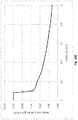
- FIG. 17depicts the lowest blade natural frequencies at a collective setting of zero as a function of rotor speed.
- the rays emanating from the origindepict the 1/rev, 2/rev . . . 10/rev harmonic frequencies of the rotor.
- Operating speed rangesare marked on the horizontal axis.
- the stiffness and mass distributions of FIGS. 16A-Fare the primary influences on the rotor blade natural frequencies.
- the natural frequenciesremain well separated from each other across the operating range. As a result of the high stiffness to weight design, the natural frequencies are much higher than typical rotor blades.
- the first flap moderemains above the 3/rev excitation frequency of the rotor across the entire operating range whereas the more lightly damped first lag mode remains above the 4/rev excitation frequency.
- This separation above the primary rotor excitation frequency of 3/revpermits operation over a wide rotor speed range without encountering excessive vibratory loads or vibrations due to resonance.
- Rotor dynamics simulation and optimization software programssuch as CHARM and CAMRAD may be used to iterate the rotor blade design subject to the desired characteristics described.
- Finite Element Analyses (FEA) softwaremay be used for higher fidelity structural analysis, and CFD codes may be used for higher fidelity aerodynamic analysis and refinement.
- the preferred auxiliary rotor and bladesare designed following the same performance constraints as the primary rotor with a smaller diameter.
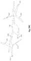
- the drive systemis enclosed in a streamlined nacelle, illustrated in FIG. 19A in the position required for wing-borne flight.
- the axis of rotation of the rotoris show as X-X and the direction of flight by Arrow A.
- Tilt rotor aircraftby definition, require the thrust axis of the rotor to be rotated from the horizontal flight condition to the vertical lift condition. This angle is not less than 90 Deg. and can be 105 Deg. or more.
- the axis about which the forward section of the nacelle tilts, including all drive elements,is shown as Y-Y.
- Blade Shanks, 1901are mounted in Feather Bearing Containment Hoops, 1902 , which are bolted to the rotating Hub, 1903 supported on large diameter Bearing, 1904 .
- the three Motors, 1905are symmetrically disposed about the hub center, one of which is shown sectioned, 1906 .
- the output Sun Gear, 1907is driven via Sprag Clutch, 1908 .
- the Planet Gears, 1909are mounted in Planet Carrier, 1910 which is attached to Output Pinion, 1911 .
- the three identical output pinionsmesh with Ring Gear, 1912 . Hub loads are carried from the hub bearing through Intermediate Structure, 1913 which is attached by bonding and riveting to Nacelle, 1914 , of monocoque composite construction.
- the shell structureis attached to the aft nacelle at Hinge Points, 1915 , with the tilt actuation Truss, 1916 , connecting both nacelle elements at actuator Attachment Bracket, 1917 .
- the electronics motor Driver Boxes, 1918are individually packaged for redundancy, with Phase Connections, 1919 to the motors.
- the motor Liquid Cooling connection, 1920is illustrated, as is the Oil Containment Sump, 1921 .
- the alternative Rotary Tilt Actuator, 1922is shown mounted on a transverse axis of rotation.
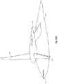
- FIG. 19Bdepicts an alternative perspective view of a portion of the streamlined nacelle depicted in FIG. 19A .
- FIG. 19Bprovides a closer view of Blade Shanks 1901 as mounted in Feather Bearing Containment Hoops 1902 , as well as the bolting of Feather Bearing Containment Hoops 1902 to rotating Hub 1903 , which is supported on large diameter Bearing 1904 .
- the entire rotor hubincluding the blade feather bearings and pitch actuation system coupled with the electric drive, form an integrated assembly.
- the systemis illustrated as a three-bladed arrangement; other blade numbers are similarly installed.
- the four predominating loads resolved through the assembly from the rotating frame to the nacelle structureare the blade flap loads, the mast moment, the thrust or lift vector and the drive torque.
- a large diameter, moment-carrying bearingconnects the rotating hub elements to the nacelle structure.
- the large, slow-turning rotorcreates a drive condition where the rotor torque/speed characteristics are well beyond the capabilities of a direct-drive motor.
- the high-speed motor with gear reductionoffers weight reduction with increasing gear ratio, and, further weight reduction is realized by multiplexing the motors. Because flight safety is of prime importance, multiplexed motors offer complete electrical redundancy. A degree of mechanical redundancy is also provided by the inclusion of a one-way clutch (“sprag” clutch) on each of the motor output shafts.
- the system illustratedhas three motors but is adaptable to a larger complement of motors.
- the weight breakpointis near 2000 RPM.
- the primary rotor RPM in high-power hoveris 400-460 and the RPM in high-power wingborne climb is 350, resulting in a clear preference of a geared rotor drive.
- the gearbox weightis driven by the high-torque output stage, to first order, the gearbox weight is independent of the gear ratio. As shown in FIG. 20 , the weight of the motors scale inversely with RPM. However, the weight savings is limited by the reduced ability for heat dissipation as size decreases. In addition, there are practical limitations to motor RPM that include: retention of magnets under high centrifugal force (for motors of that design type), limitations in available bearing speeds, and limitations of electronic switching speeds for motor commutation.
- gear ratio of 20:1provides weight reduction while limiting the challenges of very high motor RPMs.
- the gearboxmay have ratios of 3:1, 5:1, 10:1, 20:1, or 30:1.
- Each motoris equipped with a planetary reduction set driving a combining ring gear attached to the hub. All features of the assembly are optimized for minimum weight, for example, the use of three driver pinions engaging with a single large ring gear minimizes the face width of the ring with consequent material saving.
- the motors, their driver electronics and the gearbox in totalrequire cooling.
- the preferred fluid for motor and electronics coolingis water/glycol, and a further liquid-to-oil heat exchanger is employed for gearbox oil cooling.
- Gearbox oilis contained in a sump located at the lower aft extremity of the gearbox housing.
- the nacelle tilt systemis shown as system of three linear actuators, the aft. pair providing 60 Deg. of nacelle travel and the fwd. actuator the remaining 55 Deg.
- An alternative systemis the application of a high-torque rotary actuator operating through a four-bar linkage.
- the rotary actuatorU.S. Pat. No. 7,871,033 (Karem et al.) which describes its execution in detail, is cited in the references.
- individual blade control (IBC) actuators 2101enable precise, independent control of the rotor blade trajectories. By independently controlling the blade angle, the rotor moment and forces can be controlled.
- FIG. 22shows a similar to that depicted in FIG. 11 , except that first tilting rotor system 2210 and first tilting auxiliary rotor system 2240 are 4-blade rotor applications.
- IBC actuation with a 4-blade rotorenables aircraft braking (negative rotor thrust) in wingborne flight without introducing large hub moments. All elements similarly numbered as in FIG. 11 are described as above.
- FIG. 21AA preferred IBC configuration is shown in FIG. 21A .
- the design approachis to locate an electric actuator within the blade itself, positioned so the actuator and blade feather axes are concurrent. Certain blade design conditions have to be met for this approach to be feasible.
- OSTR rotor bladesshould, with great advantage, have a high stiffness in flap bending and lead-lag which leads to blade root section chords and thicknesses much larger than seen in conventional rotor blades.
- the resultant blade sparbeing hollow and of adequate diameter, conveniently accepts the cylindrical electric actuator.
- electric motor drivecan connect the blade to the hub in a rotational sense without the need for mechanical links and can be commanded and controlled exactly as other flight control actuators.
- the general term applied to this type of actuationis Individual Blade Control (IBC) which permits an entirely new and optimized matrix of blade azimuth and pitch angle. There are aerodynamic advantages in doing so.
- IBCIndividual Blade Control
- Hollow Blade Spar, 2101is inserted into receiving bore of Hub, 2102 supporting the blade by Bearing, 2103 running on Inner Race, 2104 and sealed by Seal, 2105 . If required to fold, the blade and hub portion rotates about Hinge, 2106 .
- Either one Motor Stator, 2107 , or, two Motor Stators, 2107 and 2108operate Rotor, 2109 , guided by Tail Bearing, 2110 and Rotor Bearing, 2111 .
- the motor rotors position and hence blade angular positionis sensed by Encoder, 2112 with a static reference by means of Stationary Core, 2113 .
- the motorsdrive the Gearbox, 2114 , which is secured to the blade root by Fastenings, 2115 .
- the gearbox reaction torqueis carried by Flexible Coupling, 2116 , whose purpose is to isolate the gearbox from moment-induced deflections resulting from blade flap and lead-lag loads. Centrifugal loads as well as moment-induced radial loads are carried by Taper Roller Bearing, 2117 . Blade actuation torque is reacted through Spline, 2117 and the Centrifugal Force is reacted by Nut, 2119 . Flexible electrical Connection Cable, 2120 carries motor power and control information from Slip Ring, 2121 , which rotates about Hub Rotation Axis, 2122 (shown by Axis X-X) with the static portion of the slip ring supported by Airframe Structure, 2123 . The Coolant Fluid flow and return lines, 2124 , are fed through Rotary Gland, 2125 .
- FIG. 21Bshows an alternative component layout. If the rotor blade is not required to fold, and the blade feather axis is tightly controlled relative to the hub by means of rigid feather bearings, then the pitch actuator can be hub-mounted as opposed to blade-mounted.
- the actuator assemblyconsisting of motor or motors, the reduction gearbox and the required sensors and connection wiring is connected to the hub. This connection is torsional stiff, but flexible in alignment to accept the deflections inherent in highly-loaded blades.
- the splined output drive discmates with an engaging spline internal to the blade.
- Cylindrical blade spar, 2131is supported in the Outboard Feather Bearing Assembly consisting of Bearing Retainer Hoop, 2132 , Outer Race, 2133 , Rollers and Cage, 2134 , Inner Race, 2135 , and Seals, 2136 .
- the blade rootis stabilized with Inner Diaphragm, 2137 , secured with Rivets, 2138 .
- the diaphragmis internally splined at 2139 for torque transfer from the Flexible Drive Bellows, 2140 . This is the point of separation when the removed blade is withdrawn over the fixed actuator.
- the Split Blade Retaining Clamp, 2141secures the Inboard Root Fitting, 2142 , to the Inboard Feather Bearing Outer Race, 2143 .
- the Taper Roller and Cage, 2144runs on Inner Race, 2145 , sealed by Seal, 2146 .
- Bearing pre-loadis provided by Belleville Spring, 2147 , operating on Thrust Washer, 2148 .
- Blade centrifugal forceis reacted by Actuator Housing, 2149 , retained by Fastener Set, 2150 which also secures Static Core, 2151 to the Rotating Hub Component, 2152 .
- the static corecarries both Motor Stator Windings, 2153 and the Position Encoder, 2154 .
- the electric motor Rotor, 2155is supported in Journal Bearing, 2156 and Tail Bearing, 2157 , and drives the Reduction Gearbox, 2158 .
- a tubular Extension, 2159attached to airframe structure, non-rotating, carries Slip Ring, 2160 , providing current and control signals to the actuator via fixed wiring Harness, 2161 .
- the preferred battery installationis shown in the nacelle cross sectional view in FIG. 23A .
- the battery 2301is disposed below the wing 2302 and internal to the nacelle 2303 . Flight direction is indicated by block arrow B.
- the aft volume of the nacelleincludes sufficient volume to include portions of the cooling system required for the electric propulsion system.
- the battery 2311can be contained in the wing structure 2312 as shown in FIG. 23B .
- the battery 2311is shown of smaller cross-sectional dimensions than in FIG. 23A but it provides the same volume because it is enclosed by the long wing 2321 .
- the nacelle 2313can then be significantly smaller and lower drag than in the primary preferred embodiment.
- a nacelle arrangement with an internal combustion engine and a generatorhybrid propulsion
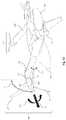
- FIGS. 24A-Gshow an alternative preferred embodiment without auxiliary rotors.
- This preferred embodimentuses the powerful pitch control of the primary rotors 2401 in rotor borne flight and the pitch control of a long control arm canard surface 2411 in wingborne flight to make possible an aircraft with lower weight, drag, installed power and cost, providing the same aircraft performance but with reduced aircraft control in transition and in wind gust and reduced level of accommodation of C.G. shift and payload versatility (no cargo ramp and reduced luggage volume and weight) as compared to the preferred embodiment with the auxiliary rotors and large tail area.
- the alternative preferred embodimentfeatures a fuselage 2421 , wing 2431 , rotor blades 2401 , and canard 2411 .
- the internal configurationis similar to the primary preferred embodiment.
- the fuselagehas 3 rows of seating: front row 2501 , middle row 2502 , and aft row 2503 .
- While the cabin volume of the 2-rotor alternative configurationis comparable to that of the one with the 4 rotors, its wingborne drag is reduced by: a) wing area reduced from 250 Ft ⁇ 2 to 140 Ft ⁇ 2, b) no tail section, c) no auxiliary rotor nacelles, d) wing to fuselage attachment behind the cabin (lower frontal area), e) option for extensive fuselage laminar flow, and f) lower cruise drag due to lower cruise weight (estimated as 817 Lb lighter due to a lighter airframe and smaller battery).
- FIGS. 25A and 25Bshow the inboard profile of the 2-rotor alternative configuration demonstrating a 3-row seating comparable to that of the 4 rotors configuration.
- FIG. 26is a table of dimensions and parameters of the 2-rotor alternative configuration.
Landscapes
- Engineering & Computer Science (AREA)
- Aviation & Aerospace Engineering (AREA)
- Mechanical Engineering (AREA)
- Automation & Control Theory (AREA)
- Transportation (AREA)
- Manufacturing & Machinery (AREA)
- Chemical & Material Sciences (AREA)
- Combustion & Propulsion (AREA)
- Transmission Devices (AREA)
- Toys (AREA)
- Wind Motors (AREA)
- Other Liquid Machine Or Engine Such As Wave Power Use (AREA)
- Retarders (AREA)
Abstract
Description
- Automobiles—these are the easiest vehicles to adopt electric power. Automobiles can accept heavy batteries, there is a relatively low battery drain rate, and operation can be safely stopped with depletion of the battery.
- Powered sailplanes—Here a powerplant is used for launching an otherwise safe glider.
- Fixed-wing training aircraft—useful for flights of short duration, operated from established airports with professional instructors, maintenance, and management.
- Privately owned fixed-wing—next easiest due rolling take-off and landing with a high wingborne lift to drag ratio.
- Electric VTOL (eVTOL)—more challenging due the high power required for hover, especially if high-speed efficient cruise is also required
Claims (23)
Priority Applications (5)
| Application Number | Priority Date | Filing Date | Title |
|---|---|---|---|
| US16/155,669US11066159B2 (en) | 2017-05-22 | 2018-10-09 | EVTOL aircraft using large, variable speed tilt rotors |
| US16/872,017US11964755B2 (en) | 2017-05-22 | 2020-05-11 | Tilt actuator for aircraft |
| US17/513,804US20220048619A1 (en) | 2017-05-22 | 2021-10-28 | Propulsion system blade with internal actuator |
| US19/209,431US20250269954A1 (en) | 2017-05-22 | 2025-05-15 | Battery and engine architecture for vtol aircraft |
| US19/209,424US12404020B1 (en) | 2017-05-22 | 2025-05-15 | VTOL aircraft using large, variable speed tilt rotors |
Applications Claiming Priority (5)
| Application Number | Priority Date | Filing Date | Title |
|---|---|---|---|
| US201762509666P | 2017-05-22 | 2017-05-22 | |
| US201762509674P | 2017-05-22 | 2017-05-22 | |
| US201862656971P | 2018-04-12 | 2018-04-12 | |
| US15/985,507US10351235B2 (en) | 2017-05-22 | 2018-05-21 | EVTOL aircraft using large, variable speed tilt rotors |
| US16/155,669US11066159B2 (en) | 2017-05-22 | 2018-10-09 | EVTOL aircraft using large, variable speed tilt rotors |
Related Parent Applications (1)
| Application Number | Title | Priority Date | Filing Date |
|---|---|---|---|
| US15/985,507DivisionUS10351235B2 (en) | 2017-05-22 | 2018-05-21 | EVTOL aircraft using large, variable speed tilt rotors |
Related Child Applications (1)
| Application Number | Title | Priority Date | Filing Date |
|---|---|---|---|
| US16/872,017DivisionUS11964755B2 (en) | 2017-05-22 | 2020-05-11 | Tilt actuator for aircraft |
Publications (2)
| Publication Number | Publication Date |
|---|---|
| US20190100304A1 US20190100304A1 (en) | 2019-04-04 |
| US11066159B2true US11066159B2 (en) | 2021-07-20 |
Family
ID=64270534
Family Applications (6)
| Application Number | Title | Priority Date | Filing Date |
|---|---|---|---|
| US15/985,507ActiveUS10351235B2 (en) | 2017-05-22 | 2018-05-21 | EVTOL aircraft using large, variable speed tilt rotors |
| US16/155,669Active2039-08-07US11066159B2 (en) | 2017-05-22 | 2018-10-09 | EVTOL aircraft using large, variable speed tilt rotors |
| US16/872,017Active2040-07-30US11964755B2 (en) | 2017-05-22 | 2020-05-11 | Tilt actuator for aircraft |
| US17/513,804PendingUS20220048619A1 (en) | 2017-05-22 | 2021-10-28 | Propulsion system blade with internal actuator |
| US19/209,424ActiveUS12404020B1 (en) | 2017-05-22 | 2025-05-15 | VTOL aircraft using large, variable speed tilt rotors |
| US19/209,431PendingUS20250269954A1 (en) | 2017-05-22 | 2025-05-15 | Battery and engine architecture for vtol aircraft |
Family Applications Before (1)
| Application Number | Title | Priority Date | Filing Date |
|---|---|---|---|
| US15/985,507ActiveUS10351235B2 (en) | 2017-05-22 | 2018-05-21 | EVTOL aircraft using large, variable speed tilt rotors |
Family Applications After (4)
| Application Number | Title | Priority Date | Filing Date |
|---|---|---|---|
| US16/872,017Active2040-07-30US11964755B2 (en) | 2017-05-22 | 2020-05-11 | Tilt actuator for aircraft |
| US17/513,804PendingUS20220048619A1 (en) | 2017-05-22 | 2021-10-28 | Propulsion system blade with internal actuator |
| US19/209,424ActiveUS12404020B1 (en) | 2017-05-22 | 2025-05-15 | VTOL aircraft using large, variable speed tilt rotors |
| US19/209,431PendingUS20250269954A1 (en) | 2017-05-22 | 2025-05-15 | Battery and engine architecture for vtol aircraft |
Country Status (6)
| Country | Link |
|---|---|
| US (6) | US10351235B2 (en) |
| EP (2) | EP4606699A3 (en) |
| JP (3) | JP6955280B2 (en) |
| KR (4) | KR102627083B1 (en) |
| CN (1) | CN110650889B (en) |
| WO (1) | WO2018217667A1 (en) |
Cited By (3)
| Publication number | Priority date | Publication date | Assignee | Title |
|---|---|---|---|---|
| US11440671B2 (en)* | 2019-01-24 | 2022-09-13 | Amazon Technologies, Inc. | Adjustable motor fairings for aerial vehicles |
| WO2024020362A1 (en)* | 2022-07-21 | 2024-01-25 | Overair Inc. | Mast moment sensing for an aircraft |
| US12420922B2 (en) | 2021-07-31 | 2025-09-23 | Supernal, Llc | Vertical take-off and landing craft systems and methods |
Families Citing this family (76)
| Publication number | Priority date | Publication date | Assignee | Title |
|---|---|---|---|---|
| US10421540B1 (en)* | 2017-03-02 | 2019-09-24 | Bell Textron Inc. | Tiltrotor aircraft having optimized hover capabilities |
| KR102627083B1 (en)* | 2017-05-22 | 2024-01-18 | 오버에어, 인코퍼레이티드 | Evtol aircraft using large, variable speed tilt rotors |
| US10974826B2 (en)* | 2017-05-22 | 2021-04-13 | Overair, Inc. | EVTOL having many variable speed tilt rotors |
| US10329014B2 (en)* | 2017-05-26 | 2019-06-25 | Bell Helicopter Textron Inc. | Aircraft having M-wings |
| US10618656B2 (en)* | 2017-10-04 | 2020-04-14 | Textron Innovations Inc. | Tiltrotor aircraft having interchangeable payload modules |
| US11053004B2 (en)* | 2017-10-17 | 2021-07-06 | Periscope Aviation, Llc | Aerodynamic drone using airfoil-designed fuselages and associated parts |
| CA3080796A1 (en)* | 2017-11-02 | 2019-05-09 | Peter F. SHANNON | Vertiport management platform |
| US11328611B2 (en) | 2017-11-02 | 2022-05-10 | Peter F. SHANNON | Vertiport management platform |
| US11034445B2 (en)* | 2017-11-27 | 2021-06-15 | Wing Aviation Llc | Wing structure and attachment to frame for unmanned aerial vehicles |
| US10723433B2 (en) | 2017-11-27 | 2020-07-28 | Wing Aviation Llc | Assembly systems and methods for unmanned aerial vehicles |
| US11260972B2 (en)* | 2018-01-24 | 2022-03-01 | Arizona Board Of Regents On Behalf Of Arizona State University | Systems and methods for a foldable unmanned aerial vehicle having a laminate structure |
| US11453513B2 (en) | 2018-04-26 | 2022-09-27 | Skydio, Inc. | Autonomous aerial vehicle hardware configuration |
| FR3086641B1 (en)* | 2018-09-28 | 2020-09-04 | Airbus Helicopters | ELECTRIC OR HYBRID MOTORIZED MULTIROTOR AIRCRAFT WITH OPTIMIZED ENERGY CONSUMPTION |
| US10988248B2 (en)* | 2019-04-25 | 2021-04-27 | Joby Aero, Inc. | VTOL aircraft |
| CN110188504B (en)* | 2019-06-11 | 2020-04-17 | 武汉理工大学 | Method for analyzing support rigidity of driven gear of main reducer of reducer shell and rear axle housing |
| US11186367B2 (en) | 2019-06-11 | 2021-11-30 | The Suppes Family Trust | Multicopter with improved failsafe operation |
| US11148791B2 (en)* | 2019-06-27 | 2021-10-19 | Harry Messimore | Hybrid power tri-propeller helicopter apparatus |
| EP3757410B1 (en)* | 2019-06-28 | 2021-11-03 | Airbus Operations (S.A.S.) | Bearing assembly of a hinge coupling a first component and a second component |
| CN114555465A (en)* | 2019-07-26 | 2022-05-27 | 优飞科技私人有限公司 | Lift enhancement assembly for aircraft with fixed wings |
| CN114286782B (en)* | 2019-08-28 | 2024-09-10 | 株式会社电装 | Control device of electric vertical lifting machine |
| EP4592189A3 (en) | 2019-10-09 | 2025-09-03 | Kitty Hawk Corporation | Hybrid power systems for different modes of flight |
| US12110106B2 (en)* | 2019-10-28 | 2024-10-08 | Joby Aero, Inc. | Aerial vehicle with differential control mechanisms |
| CN111017231B (en)* | 2019-11-28 | 2021-06-29 | 嘉兴安行信息科技有限公司 | Mounting structure of engine among unmanned aerial vehicle |
| CN110901890A (en)* | 2019-12-04 | 2020-03-24 | 中国直升机设计研究所 | High-speed rotor craft with rotor capable of being designed in classification mode |
| KR20210088052A (en) | 2020-01-03 | 2021-07-14 | 현대자동차주식회사 | Verticla takeoff and landing air mobility |
| US11738862B2 (en) | 2020-01-28 | 2023-08-29 | Overair, Inc. | Fail-operational vtol aircraft |
| US11465738B2 (en)* | 2020-01-28 | 2022-10-11 | Overair, Inc. | Fail-operational VTOL aircraft |
| WO2021225651A2 (en)* | 2020-02-06 | 2021-11-11 | Suppes Galen J | Flat plate airfoil platform vehicle |
| US12006030B2 (en) | 2020-04-24 | 2024-06-11 | United States Of America As Represented By The Administrator Of Nasa | Distributed electric propulsion modular wing aircraft with blown wing and extreme flaps for VTOL and/or STOL flight |
| WO2021222528A1 (en)* | 2020-05-01 | 2021-11-04 | Overair, Inc. | Adaptive cooling system for an aircraft |
| WO2021224593A1 (en) | 2020-05-07 | 2021-11-11 | Bae Systems Plc | Rotorcraft |
| EP4146538B1 (en) | 2020-05-07 | 2024-11-06 | BAE SYSTEMS plc | Rotorcraft |
| GB2594744B (en)* | 2020-05-07 | 2024-04-03 | Bae Systems Plc | Rotorcraft |
| KR20210138441A (en) | 2020-05-12 | 2021-11-19 | 현대자동차주식회사 | Control system and control method of air mobility |
| DE102021111923B4 (en)* | 2020-10-02 | 2025-08-14 | Obrist Technologies Gmbh | aircraft |
| JP2022092705A (en)* | 2020-12-11 | 2022-06-23 | quintuple air株式会社 | Flight body |
| US11760473B2 (en) | 2021-02-11 | 2023-09-19 | Karem Aircraft, Inc. | Rotorcraft with interchangeable rotor diameters |
| JP7012227B1 (en)* | 2021-02-15 | 2022-01-28 | 株式会社松山ドローンサービス | Flying object |
| KR102370186B1 (en)* | 2021-04-05 | 2022-03-07 | (주)팔로우테크닉스 | Cable Aerial Vehicle |
| USD978768S1 (en) | 2021-05-13 | 2023-02-21 | Alakai Technologies Corporation | Aircraft airframe |
| US11353889B1 (en) | 2021-06-16 | 2022-06-07 | Beta Air, Llc | System for electric aircraft navigation |
| US12183212B2 (en) | 2021-06-16 | 2024-12-31 | Beta Air Llc | System for electric aircraft navigation |
| IT202100018170A1 (en) | 2021-07-09 | 2023-01-09 | Gen Electric | HYBRID ELECTRIC AIRPLANE WITH GYRO STABILIZATION CONTROL |
| US11392143B1 (en)* | 2021-07-23 | 2022-07-19 | Beta Air, Llc | System and method for producing a control signal of an electric vertical take-off and landing (eVTOL) aircraft |
| US20230067713A1 (en)* | 2021-08-27 | 2023-03-02 | Aerhart, LLC | Vertical Takeoff and Landing Aeronautical Apparatus with a Folding Wing |
| CN113525679B (en)* | 2021-08-30 | 2025-08-29 | 上海时的科技有限公司 | An electric vertical take-off and landing aircraft structure and working method thereof |
| MX2024004577A (en)* | 2021-10-15 | 2024-07-10 | Real Time Robotics Inc | A MULTICOPTER. |
| JP7571002B2 (en) | 2021-12-22 | 2024-10-22 | 本田技研工業株式会社 | aircraft |
| CN114001919B (en)* | 2022-01-04 | 2022-03-15 | 中国空气动力研究与发展中心低速空气动力研究所 | Ground simulation method for full-size tilt rotor axial flow forward flight performance test |
| US11790790B2 (en)* | 2022-01-13 | 2023-10-17 | Beta Air, Llc | Methods and apparatuses for generating an electric aircraft flight plan |
| EP4227222B1 (en)* | 2022-02-09 | 2024-05-29 | Lilium eAircraft GmbH | Airfoil of an aircraft with an ice protection system, aircraft with the airfoil and method of ice protecting the airfoil |
| US12107459B2 (en) | 2022-03-25 | 2024-10-01 | Beta Air Llc | Rotor for an electric aircraft motor comprising a plurality of magnets |
| US12043400B2 (en) | 2022-03-29 | 2024-07-23 | Toyota Motor Engineering & Manufacturing North America, Inc. | Cooling system for aircraft components including ram chute body and relatively rotatable air conduit |
| US12227296B2 (en) | 2022-03-30 | 2025-02-18 | Toyota Motor Engineering & Manufacturing North America, Inc. | Cooling system for aircraft components |
| US12332659B2 (en) | 2022-04-29 | 2025-06-17 | Beta Air Llc | System for propeller parking control for an electric aircraft and a method for its use |
| US11691721B1 (en) | 2022-04-29 | 2023-07-04 | Beta Air, Llc | System for propeller parking control for an electric aircraft and a method for its use |
| US11634232B1 (en)* | 2022-04-30 | 2023-04-25 | Beta Air, Llc | Hybrid propulsion systems for an electric aircraft |
| US12195192B2 (en)* | 2022-04-30 | 2025-01-14 | Beta Air Llc | Hybrid propulsion systems for an electric aircraft |
| US11639230B1 (en)* | 2022-04-30 | 2023-05-02 | Beta Air, Llc | System for an integral hybrid electric aircraft |
| CN115127589B (en)* | 2022-06-14 | 2024-04-30 | 西北工业大学 | A distributed fault-tolerant relative navigation method under wing deflection |
| WO2024059777A1 (en)* | 2022-09-16 | 2024-03-21 | Overair Inc. | Proprotor hub for an aircraft |
| US11787551B1 (en) | 2022-10-06 | 2023-10-17 | Archer Aviation, Inc. | Vertical takeoff and landing aircraft electric engine configuration |
| US20240270393A1 (en) | 2022-10-06 | 2024-08-15 | Archer Aviation Inc. | SYSTEMS AND METHODS FOR OIL MAINTENANCE IN GEARBOXES FOR eVTOL AIRCRAFT |
| US12312091B2 (en) | 2022-10-06 | 2025-05-27 | Archer Aviation Inc. | Systems and methods for improved gearboxes for evtol aircraft |
| KR102538151B1 (en)* | 2022-10-19 | 2023-05-30 | 주식회사 플라나 | Battery cooling structure and fuselage including the same |
| US20240228036A9 (en)* | 2022-10-24 | 2024-07-11 | Textron Aviation Inc. | Electric Aircraft |
| US12358616B2 (en) | 2022-11-02 | 2025-07-15 | Leviation Technology, Inc. | Compound vertical takeoff and landing aircraft |
| US12337992B2 (en)* | 2022-12-01 | 2025-06-24 | Kara E. Johnson | Aircraft takeoff and landing apparatus |
| CN115700210A (en)* | 2022-12-02 | 2023-02-07 | 书禹教育科技(上海)有限公司 | A manned aircraft with injection molded front flap, coaxial anti-slurry engine and two-wing flight attitude conversion |
| CN116080945B (en)* | 2022-12-08 | 2023-10-20 | 深圳市生态环境智能管控中心 | Multi-rotor unmanned aerial vehicle capable of switching flight postures and flight method |
| KR102855608B1 (en)* | 2023-06-26 | 2025-09-05 | 건국대학교 산학협력단 | Estimation and separation method of dynamic stability derivatives of urban air mobility aircraft |
| CN116853489B (en)* | 2023-07-25 | 2025-06-27 | 四川沃飞长空科技发展有限公司 | Aircraft and method for designing tilting device |
| JP2025018025A (en)* | 2023-07-26 | 2025-02-06 | 川崎重工業株式会社 | Aircraft Propulsion Systems |
| JP2025018024A (en)* | 2023-07-26 | 2025-02-06 | 川崎重工業株式会社 | Aircraft Propulsion Systems |
| CN116853491B (en)* | 2023-09-01 | 2023-11-07 | 成都沃飞天驭科技有限公司 | Tilt device, design method and aircraft thereof |
| KR102698822B1 (en) | 2023-10-31 | 2024-08-26 | 한화시스템 주식회사 | Rotor shape design method and apparatus for urban air mobility |
Citations (50)
| Publication number | Priority date | Publication date | Assignee | Title |
|---|---|---|---|---|
| GB598879A (en)* | 1945-09-21 | 1948-02-27 | Fairey Aviat Co Ltd | Improvements in or relating to rotary wing aircraft |
| US3292710A (en)* | 1964-11-23 | 1966-12-20 | Hugo T Grut | Variable pitch propeller or rotor |
| US3494707A (en)* | 1967-12-29 | 1970-02-10 | Boeing Co | Convertiplane |
| US4979698A (en)* | 1988-07-07 | 1990-12-25 | Paul Lederman | Rotor system for winged aircraft |
| US5765783A (en)* | 1994-03-04 | 1998-06-16 | The Boeing Company | Vertically launchable and recoverable winged aircraft |
| CA2315524A1 (en) | 2000-07-28 | 2001-05-21 | John F. Austen-Brown | Personal hoverplane having four tiltmotors |
| US6276633B1 (en) | 1999-03-25 | 2001-08-21 | Eurocopter | Convertible aircraft with tilting rotors |
| US20100193644A1 (en)* | 2008-04-25 | 2010-08-05 | Abe Karem | Aircraft with Integrated Lift and Propulsion System |
| US20110024552A1 (en)* | 2008-04-25 | 2011-02-03 | Karem Aircraft, Inc. | Anhedral Tip Blades for Tiltrotor Aircraft |
| US20110024555A1 (en) | 2009-01-27 | 2011-02-03 | Kuhn Jr Ira Francis | Purebred and Hybrid Electric VTOL Tilt Rotor Aircraft |
| US8083172B2 (en)* | 2008-04-25 | 2011-12-27 | Abe Karem | Combination spar and trunnion structure for a tilt rotor aircraft |
| US20120043413A1 (en) | 2005-10-18 | 2012-02-23 | Smith Frick A | Apparatus and method for vertical take-off and landing aircraft |
| US8376264B1 (en)* | 2009-08-24 | 2013-02-19 | Jianhui Hong | Rotor for a dual mode aircraft |
| US20140061392A1 (en)* | 2005-08-15 | 2014-03-06 | Abe Karem | Aircraft With Integrated Lift And Propulsion System |
| US20140338372A1 (en) | 2013-05-17 | 2014-11-20 | REbound Technology LLC | Methods, Systems, and Devices for Producing a Heat Pump |
| US8931732B2 (en) | 2007-11-30 | 2015-01-13 | Sikorsky Aircraft Corporation | Electric powered rotary-wing aircraft |
| KR20150058197A (en) | 2012-09-23 | 2015-05-28 | 이스라엘 에어로스페이스 인더스트리즈 리미티드 | A system, a method and a computer program product for maneuvering of an air vehicle |
| US20150274292A1 (en) | 2012-12-07 | 2015-10-01 | Delorean Aerospace, Llc | Vertical takeoff and landing aircraft |
| US20160031555A1 (en) | 2014-03-18 | 2016-02-04 | Joby Aviation, Inc. | Aerodynamically efficient lightweight vertical take-off and landing aircraft with pivoting rotors and stowing rotor blades |
| US20160031556A1 (en) | 2014-03-18 | 2016-02-04 | Joby Aviation, Inc. | Impact Resistant Propeller System, Fast Response Electric Propulsion System And Lightweight Vertical Take-Off And Landing Aircraft Using Same |
| US20160076629A1 (en) | 2014-04-10 | 2016-03-17 | Bell Helicopter Textron Inc. | Variable speed aircraft transmission |
| US9346542B2 (en) | 2012-10-05 | 2016-05-24 | Skykar Inc. | Electrically powered aerial vehicles and flight control methods |
| US20160200436A1 (en)* | 2013-08-13 | 2016-07-14 | U.S.A. As Represented By The Administrator Of The National Aeronautics And Space Administration | Tri-Rotor Aircraft Capable of Vertical Takeoff and Landing and Transitioning to Forward Flight |
| US20160244158A1 (en)* | 2013-08-13 | 2016-08-25 | Usa As Represented By The Administrator Of The National Aeronautics And Space Adminstration | Vertical take-off and landing vehicle with increased cruise efficiency |
| US20160280369A1 (en)* | 2013-11-01 | 2016-09-29 | The University Of Queensland | Rotorcraft |
| US20160304194A1 (en) | 2014-03-18 | 2016-10-20 | Joby Aviation, Inc. | Articulated Electric Propulsion System With Fully Stowing Blades And Lightweight Vertical Take-Off And Landing Aircraft Using Same |
| US20160340038A1 (en) | 2015-03-26 | 2016-11-24 | Bell Helicopter Textron Inc. | Integrated aircraft hoist |
| US20170088291A1 (en) | 2015-03-05 | 2017-03-30 | Thomas Norman Hesse | Gyroscopic Orbiter with Vertical Takeoff and Vertical Landing Capabilities |
| WO2017158417A1 (en) | 2016-03-15 | 2017-09-21 | Navis S.R.L. | Vertical take off and landing aircraft with four tilting wings and electric motors |
| US9856029B2 (en)* | 2013-08-14 | 2018-01-02 | Bell Helicopter Textron Inc. | Tiltrotor aircraft having tip rib mounted pylon assemblies |
| US20180002012A1 (en) | 2016-07-01 | 2018-01-04 | Bell Helicopter Textron Inc. | Aircraft with Independently Controllable Propulsion Assemblies |
| US20180002011A1 (en) | 2016-07-01 | 2018-01-04 | Bell Helicopter Textron Inc. | Aircraft with Selectively Attachable Passenger Pod Assembly |
| US9868541B2 (en)* | 2013-08-14 | 2018-01-16 | Bell Helicopter Textron Inc. | Tiltrotor aircraft having journal bearing mounted pylon assemblies |
| US20180057148A1 (en) | 2016-08-31 | 2018-03-01 | Bell Helicopter Textron Inc. | Tiltrotor Aircraft having Active Wing Extensions |
| US20180057159A1 (en) | 2016-08-31 | 2018-03-01 | Bell Helicopter Textron Inc. | Tiltrotor Aircraft having Rotatable Wing Extensions |
| US20180141671A1 (en) | 2016-11-22 | 2018-05-24 | Honeywell International Inc. | Hybrid electric aircraft propulsion system with motors using induction effect |
| WO2018099856A1 (en) | 2016-11-29 | 2018-06-07 | Pfammatter Thomas | Electrical vertical take-off and landing aircraft |
| US20180155019A1 (en) | 2016-11-28 | 2018-06-07 | Korea Aerospace Research Institute | Tilt-prop aircraft |
| US10053213B1 (en) | 2017-05-08 | 2018-08-21 | Pinnacle Vista, LLC | Multi-copter lift body aircraft with tail pusher |
| US20180290742A1 (en) | 2016-07-01 | 2018-10-11 | Bell Helicopter Textron Inc. | Two-Axis Gimbal Mounted Propulsion Systems for Aircraft |
| US20180297698A1 (en) | 2017-04-13 | 2018-10-18 | Sanjay Dhall | Aircraft Having Telescopic Wings and Tilting Motor Assemblies |
| US20180305005A1 (en)* | 2017-04-24 | 2018-10-25 | AFS-DV VTOL Technologies Corporation | Vertical Take-Off and Landing Aircraft |
| US20190135425A1 (en)* | 2017-11-03 | 2019-05-09 | Uber Technologies, Inc. | Vtol m-wing configuration |
| US20190263515A1 (en)* | 2017-05-22 | 2019-08-29 | Karem Aircraft, Inc. | eVTOL Having Many Variable Speed Tilt Rotors |
| US20190291862A1 (en) | 2016-05-18 | 2019-09-26 | A^3 By Airbus Llc | Self-piloted aircraft for passenger or cargo transportation |
| US20190329882A1 (en) | 2018-04-27 | 2019-10-31 | Aai Corporation | Variable pitch rotor assembly for electrically driven vectored thrust aircraft applications |
| WO2019232535A1 (en) | 2018-06-01 | 2019-12-05 | Joby Aero, Inc. | System and method for aircraft noise mitigation |
| US20200010187A1 (en) | 2018-05-31 | 2020-01-09 | Joby Aero, Inc. | Electric power system architecture and fault tolerant vtol aircraft using same |
| US20200017204A1 (en)* | 2018-07-13 | 2020-01-16 | The Boeing Company | Canted co-axial rotors for a rotorcraft |
| US20200023963A1 (en)* | 2018-07-13 | 2020-01-23 | Rolls-Royce Plc | Vertical take-off and landing aircraft |
Family Cites Families (81)
| Publication number | Priority date | Publication date | Assignee | Title |
|---|---|---|---|---|
| GB400735A (en)* | 1931-12-31 | 1933-11-02 | Harold Bolas | Improvements in or relating to aircraft |
| US2957364A (en)* | 1954-12-09 | 1960-10-25 | Ile Office Tech Internat O T I | Electromagnetic and electromechanical transmissions and torque converters |
| FR1507306A (en)* | 1966-11-17 | 1967-12-29 | Sud Aviation | Connection device filtering vibrations between a vibrating member and a support, in particular a rotor and a helicopter structure |
| EP0057053A1 (en)* | 1981-01-22 | 1982-08-04 | WESTLAND plc | Helicopter rotors |
| JP3201100B2 (en) | 1993-10-25 | 2001-08-20 | 松下電器産業株式会社 | Magneto-optical disk spindle motor |
| JPH0911994A (en)* | 1995-06-30 | 1997-01-14 | Mitsubishi Heavy Ind Ltd | Pitch controller for helicopter |
| US6641365B2 (en) | 1998-02-20 | 2003-11-04 | Abraham E. Karem | Optimum speed tilt rotor |
| DE69931035T2 (en) | 1998-02-20 | 2007-05-10 | Abraham E. Lake Forest Karem | ROTOR WITH OPTIMIZED SPEED |
| US6322324B1 (en)* | 2000-03-03 | 2001-11-27 | The Boeing Company | Helicopter in-flight rotor tracking system, method, and smart actuator therefor |
| US9493235B2 (en)* | 2002-10-01 | 2016-11-15 | Dylan T X Zhou | Amphibious vertical takeoff and landing unmanned device |
| US7500935B2 (en)* | 2005-06-23 | 2009-03-10 | Karem Aircraft, Inc. | Lightweight reduction gearbox |
| US20100270435A1 (en) | 2005-08-15 | 2010-10-28 | Abe Karem | Wing efficiency for tilt-rotor aircraft |
| US8608441B2 (en) | 2006-06-12 | 2013-12-17 | Energyield Llc | Rotatable blade apparatus with individually adjustable blades |
| EP2097317A1 (en) | 2006-11-02 | 2009-09-09 | Severino Manuel Oliveira Raposo | System and process of vector propulsion with independent control of three translation and three rotation axis |
| DE102006056356A1 (en) | 2006-11-29 | 2008-06-05 | Airbus Deutschland Gmbh | Drive device for aircraft, has energy converters which are attached for supplying drive unit with operating powers, where drive unit is attached for producing form feed using one operating power |
| US20080184906A1 (en)* | 2007-02-07 | 2008-08-07 | Kejha Joseph B | Long range hybrid electric airplane |
| US8950468B2 (en) | 2007-05-11 | 2015-02-10 | The Boeing Company | Cooling system for aerospace vehicle components |
| WO2009126905A1 (en) | 2008-04-11 | 2009-10-15 | Karem Aircraft, Inc. | Tilt actuation for a rotorcraft |
| WO2010026517A2 (en)* | 2008-09-02 | 2010-03-11 | Urban Aeronautics Ltd. | Vtol vehicle with coaxially tilted or tiltable rotors |
| US20110001020A1 (en)* | 2009-07-02 | 2011-01-06 | Pavol Forgac | Quad tilt rotor aerial vehicle with stoppable rotors |
| ITTO20090632A1 (en)* | 2009-08-11 | 2011-02-12 | Santino Pancotti | TILTROTOR |
| US8616492B2 (en)* | 2009-10-09 | 2013-12-31 | Oliver Vtol, Llc | Three wing, six tilt-propulsion units, VTOL aircraft |
| FR2954273B1 (en)* | 2009-12-17 | 2012-02-24 | Eurocopter France | ROTOR CARRIER STRUCTURE AND FLYING APPARATUS PROVIDED WITH SUCH A CARRIER STRUCTURE |
| US9108727B2 (en)* | 2010-06-16 | 2015-08-18 | Sikorsky Aircraft Corporation | Blade fold system monitoring |
| JP5559621B2 (en)* | 2010-07-12 | 2014-07-23 | 川崎重工業株式会社 | Articulated rotor hub structure for rotorcraft and method for manufacturing the same |
| JP5421503B2 (en)* | 2010-07-19 | 2014-02-19 | ズィー.エアロ インコーポレイテッド | Private aircraft |
| US8602347B2 (en)* | 2011-02-04 | 2013-12-10 | Textron Innovations Inc. | Tilt rotor aircraft with fixed engine arrangement |
| FR2975668B1 (en)* | 2011-05-27 | 2013-07-05 | Eurocopter France | METHOD AND AIRCRAFT PROVIDED WITH DEVICE FOR VIBRATION REDUCTION |
| TWI538852B (en)* | 2011-07-19 | 2016-06-21 | 季航空股份有限公司 | Personal aircraft |
| IL217070A0 (en)* | 2011-12-18 | 2012-03-29 | Ofek Eshkolot Res And Dev Ltd | Aircraft with fixed and tilting thrusters |
| IL217501A (en)* | 2012-01-12 | 2017-09-28 | Israel Aerospace Ind Ltd | System and method for maneuvering of an air vehicle |
| GB2501510B (en)* | 2012-04-25 | 2019-01-09 | Mactaggart Scott | Gearbox test rig |
| DE202012013513U1 (en) | 2012-07-27 | 2017-05-12 | Jonathan Hesselbarth | Vertical airplane |
| US9694908B2 (en)* | 2012-10-16 | 2017-07-04 | Aeroxo Limited | Convertiplane (variants) |
| FR2999150B1 (en)* | 2012-12-10 | 2015-10-09 | Bermond Gerome Maurice Paul | CONVERTIBLE AIRCRAFT COMPRISING TWO CAREN ROTORS AT THE END OF A WING AND A HORIZONTAL FAN IN FUSELAGE |
| US9126678B2 (en)* | 2013-03-13 | 2015-09-08 | Bell Helicopter Textron Inc. | Spindle mounted tiltrotor pylon with fixed engine arrangement |
| CN105121188B (en) | 2013-03-15 | 2019-03-15 | 特力飞车股份有限公司 | Combined flying/driving vehicle with vertical take-off and fixed-wing cruise capabilities |
| FR3011818B1 (en)* | 2013-10-11 | 2015-12-25 | Eurocopter France | ADAPTIVE ROTATING BLADE, AND AIRCRAFT PROVIDED WITH SUCH A BLADE |
| US9296472B2 (en) | 2013-10-17 | 2016-03-29 | The Boeing Company | Wingtip control system |
| CN103693194B (en)* | 2013-12-17 | 2015-11-18 | 南京航空航天大学 | One can be verted quadrotor |
| US9294016B2 (en)* | 2013-12-19 | 2016-03-22 | Google Inc. | Control methods and systems for motors and generators operating in a stacked configuration |
| US10144509B2 (en) | 2014-06-03 | 2018-12-04 | Juan Gabriel Cruz Ayoroa | High performance VTOL aircraft |
| WO2016028358A2 (en)* | 2014-06-03 | 2016-02-25 | Juan Cruz Ayoroa | High Performance VTOL Aircraft |
| WO2016009824A1 (en)* | 2014-07-17 | 2016-01-21 | 国立研究開発法人宇宙航空研究開発機構 | Motorized aircraft and method for determining output and number of electric motors in motorized aircraft |
| IL233902B (en)* | 2014-07-31 | 2020-07-30 | Israel Aerospace Ind Ltd | egnition system |
| US11014658B1 (en)* | 2015-01-02 | 2021-05-25 | Delbert Tesar | Driveline architecture for rotorcraft featuring active response actuators |
| EP3240726B1 (en)* | 2015-01-03 | 2020-08-05 | Joseph B. Seale | Rotary wing vtol with fixed wing forward flight mode |
| US20170368608A1 (en)* | 2015-01-05 | 2017-12-28 | Sikorsky Aircraft Corporation | Integrated vibration damper for additively manufactured structure and method |
| JP2018526270A (en)* | 2015-08-31 | 2018-09-13 | ユニバーシティー オブ メリーランド,カレッジ パーク | General purpose vehicle with improved stability for safe operation in air, water and terrain environments |
| JP3201100U (en)* | 2015-09-09 | 2015-11-19 | 李宏富 | Multi-rotor variable pitch helicopter |
| JP2017059955A (en)* | 2015-09-15 | 2017-03-23 | ツネイシホールディングス株式会社 | Imaging system and computer program |
| US20170129597A1 (en)* | 2015-11-10 | 2017-05-11 | Sikorsky Aircraft Corporation | Reduced power individual blade control system on a rotorcraft |
| US20180162525A1 (en)* | 2016-12-08 | 2018-06-14 | Aurora Flight Sciences Corporation | Double-Blown Wing Vertical Takeoff and Landing Aircraft |
| US10442525B2 (en)* | 2016-05-07 | 2019-10-15 | Optivector Ltd | Rotor or propeller blade with dynamically variable geometry and other properties |
| US10633088B2 (en) | 2016-07-01 | 2020-04-28 | Textron Innovations Inc. | Aerial imaging aircraft having attitude stability during translation |
| EP3854693B1 (en) | 2016-07-27 | 2023-12-20 | Ratier-Figeac SAS | Actuator assembly and a method of reacting torque on the same |
| US10239605B2 (en)* | 2016-09-19 | 2019-03-26 | Bell Helicopter Textron Inc. | Chordwise folding and locking of rotor systems |
| GB2555439A (en)* | 2016-10-27 | 2018-05-02 | Mono Aerospace Ip Ltd | Vertical take-off and landing aircraft and control method |
| US10826343B2 (en) | 2016-11-17 | 2020-11-03 | General Electric Company | High speed electric machine with radially supported rotor magnets |
| EP3548377B1 (en)* | 2016-11-29 | 2021-08-04 | Pfammatter, Thomas | Electrical vertical take-off and landing aircraft |
| FR3060523B1 (en) | 2016-12-21 | 2019-05-17 | Safran Aircraft Engines | ELECTROMECHANICAL STEM ACTUATION SYSTEM FOR A TURBOMACHINE PROPELLER |
| US11731772B2 (en)* | 2017-03-02 | 2023-08-22 | Textron Innovations Inc. | Hybrid propulsion drive train system for tiltrotor aircraft |
| US10421540B1 (en)* | 2017-03-02 | 2019-09-24 | Bell Textron Inc. | Tiltrotor aircraft having optimized hover capabilities |
| CN106672232A (en) | 2017-03-02 | 2017-05-17 | 北京天宇新超航空科技有限公司 | Efficient vertical takeoff and landing aircraft |
| US10850835B2 (en)* | 2017-03-30 | 2020-12-01 | Qualcomm Incorporated | Unmanned aerial vehicle with monolithic wing and twin-rotor propulsion/lift modules |
| US10208629B2 (en) | 2017-03-31 | 2019-02-19 | The Boeing Company | Piezo-electric motor for bowed rotor mitigation |
| GB2550489B (en)* | 2017-05-03 | 2018-07-18 | Wirth Res Limited | An unmanned aerial vehicle |
| US10589841B2 (en)* | 2017-05-18 | 2020-03-17 | Bell Helicopter Textron Inc. | Aircraft hub fairing with movable members |
| KR102627083B1 (en) | 2017-05-22 | 2024-01-18 | 오버에어, 인코퍼레이티드 | Evtol aircraft using large, variable speed tilt rotors |
| US11203423B2 (en) | 2017-06-01 | 2021-12-21 | Karem Aircraft, Inc. | Use of individual blade control on a propeller or rotor in axial flight for the purpose of aerodynamic braking and power response modulation |
| US10543912B2 (en)* | 2017-07-19 | 2020-01-28 | Sikorsky Aircraft Corporation | Higher harmonic control augmented with active vibration control |
| WO2019056053A1 (en)* | 2017-09-22 | 2019-03-28 | AMSL Innovations Pty Ltd | Wing tilt actuation system for electric vertical take-off and landing (vtol) aircraft |
| JP2020536016A (en)* | 2017-10-02 | 2020-12-10 | カリフォルニア インスティチュート オブ テクノロジー | Autonomous flight ambulance |
| US10988248B2 (en)* | 2019-04-25 | 2021-04-27 | Joby Aero, Inc. | VTOL aircraft |
| US11505314B2 (en)* | 2019-07-22 | 2022-11-22 | Aurora Flight Sciences Corporation | Vertical takeoff and landing aircraft with tiltable rotors |
| US11465738B2 (en)* | 2020-01-28 | 2022-10-11 | Overair, Inc. | Fail-operational VTOL aircraft |
| US11572165B2 (en)* | 2020-02-19 | 2023-02-07 | Bryan B Solstin | Tandem-tiltrotor apparatus |
| WO2021222528A1 (en)* | 2020-05-01 | 2021-11-04 | Overair, Inc. | Adaptive cooling system for an aircraft |
| EP4291489A1 (en) | 2021-02-09 | 2023-12-20 | Joby Aero, Inc. | Aircraft propulsion unit |
| CN113525678B (en)* | 2021-09-17 | 2022-05-10 | 北京航空航天大学 | A tow-propulsion tilt-wing vertical take-off and landing manned aircraft |
| US11780555B1 (en)* | 2022-08-03 | 2023-10-10 | Karem Aircraft, Inc. | Ground effect wing having a flapping wingtip |
- 2018
- 2018-05-21KRKR1020227046081Apatent/KR102627083B1/enactiveActive
- 2018-05-21EPEP25169297.6Apatent/EP4606699A3/enactivePending
- 2018-05-21KRKR1020197034883Apatent/KR20190133799A/ennot_activeCeased
- 2018-05-21KRKR1020227017198Apatent/KR102483971B1/enactiveActive
- 2018-05-21EPEP18805029.8Apatent/EP3630603B1/enactiveActive
- 2018-05-21CNCN201880033495.4Apatent/CN110650889B/enactiveActive
- 2018-05-21JPJP2019565421Apatent/JP6955280B2/enactiveActive
- 2018-05-21WOPCT/US2018/033744patent/WO2018217667A1/ennot_activeCeased
- 2018-05-21USUS15/985,507patent/US10351235B2/enactiveActive
- 2018-05-21KRKR1020237035915Apatent/KR102761931B1/enactiveActive
- 2018-10-09USUS16/155,669patent/US11066159B2/enactiveActive
- 2020
- 2020-05-11USUS16/872,017patent/US11964755B2/enactiveActive
- 2021
- 2021-04-30JPJP2021077747Apatent/JP2021119080A/enactivePending
- 2021-10-28USUS17/513,804patent/US20220048619A1/enactivePending
- 2023
- 2023-06-01JPJP2023090982Apatent/JP7466963B2/enactiveActive
- 2025
- 2025-05-15USUS19/209,424patent/US12404020B1/enactiveActive
- 2025-05-15USUS19/209,431patent/US20250269954A1/enactivePending
Patent Citations (50)
| Publication number | Priority date | Publication date | Assignee | Title |
|---|---|---|---|---|
| GB598879A (en)* | 1945-09-21 | 1948-02-27 | Fairey Aviat Co Ltd | Improvements in or relating to rotary wing aircraft |
| US3292710A (en)* | 1964-11-23 | 1966-12-20 | Hugo T Grut | Variable pitch propeller or rotor |
| US3494707A (en)* | 1967-12-29 | 1970-02-10 | Boeing Co | Convertiplane |
| US4979698A (en)* | 1988-07-07 | 1990-12-25 | Paul Lederman | Rotor system for winged aircraft |
| US5765783A (en)* | 1994-03-04 | 1998-06-16 | The Boeing Company | Vertically launchable and recoverable winged aircraft |
| US6276633B1 (en) | 1999-03-25 | 2001-08-21 | Eurocopter | Convertible aircraft with tilting rotors |
| CA2315524A1 (en) | 2000-07-28 | 2001-05-21 | John F. Austen-Brown | Personal hoverplane having four tiltmotors |
| US20140061392A1 (en)* | 2005-08-15 | 2014-03-06 | Abe Karem | Aircraft With Integrated Lift And Propulsion System |
| US20120043413A1 (en) | 2005-10-18 | 2012-02-23 | Smith Frick A | Apparatus and method for vertical take-off and landing aircraft |
| US8931732B2 (en) | 2007-11-30 | 2015-01-13 | Sikorsky Aircraft Corporation | Electric powered rotary-wing aircraft |
| US8083172B2 (en)* | 2008-04-25 | 2011-12-27 | Abe Karem | Combination spar and trunnion structure for a tilt rotor aircraft |
| US20110024552A1 (en)* | 2008-04-25 | 2011-02-03 | Karem Aircraft, Inc. | Anhedral Tip Blades for Tiltrotor Aircraft |
| US20100193644A1 (en)* | 2008-04-25 | 2010-08-05 | Abe Karem | Aircraft with Integrated Lift and Propulsion System |
| US20110024555A1 (en) | 2009-01-27 | 2011-02-03 | Kuhn Jr Ira Francis | Purebred and Hybrid Electric VTOL Tilt Rotor Aircraft |
| US8376264B1 (en)* | 2009-08-24 | 2013-02-19 | Jianhui Hong | Rotor for a dual mode aircraft |
| KR20150058197A (en) | 2012-09-23 | 2015-05-28 | 이스라엘 에어로스페이스 인더스트리즈 리미티드 | A system, a method and a computer program product for maneuvering of an air vehicle |
| US9346542B2 (en) | 2012-10-05 | 2016-05-24 | Skykar Inc. | Electrically powered aerial vehicles and flight control methods |
| US20150274292A1 (en) | 2012-12-07 | 2015-10-01 | Delorean Aerospace, Llc | Vertical takeoff and landing aircraft |
| US20140338372A1 (en) | 2013-05-17 | 2014-11-20 | REbound Technology LLC | Methods, Systems, and Devices for Producing a Heat Pump |
| US20160244158A1 (en)* | 2013-08-13 | 2016-08-25 | Usa As Represented By The Administrator Of The National Aeronautics And Space Adminstration | Vertical take-off and landing vehicle with increased cruise efficiency |
| US20160200436A1 (en)* | 2013-08-13 | 2016-07-14 | U.S.A. As Represented By The Administrator Of The National Aeronautics And Space Administration | Tri-Rotor Aircraft Capable of Vertical Takeoff and Landing and Transitioning to Forward Flight |
| US9868541B2 (en)* | 2013-08-14 | 2018-01-16 | Bell Helicopter Textron Inc. | Tiltrotor aircraft having journal bearing mounted pylon assemblies |
| US9856029B2 (en)* | 2013-08-14 | 2018-01-02 | Bell Helicopter Textron Inc. | Tiltrotor aircraft having tip rib mounted pylon assemblies |
| US20160280369A1 (en)* | 2013-11-01 | 2016-09-29 | The University Of Queensland | Rotorcraft |
| US20160031555A1 (en) | 2014-03-18 | 2016-02-04 | Joby Aviation, Inc. | Aerodynamically efficient lightweight vertical take-off and landing aircraft with pivoting rotors and stowing rotor blades |
| US20160304194A1 (en) | 2014-03-18 | 2016-10-20 | Joby Aviation, Inc. | Articulated Electric Propulsion System With Fully Stowing Blades And Lightweight Vertical Take-Off And Landing Aircraft Using Same |
| US20160031556A1 (en) | 2014-03-18 | 2016-02-04 | Joby Aviation, Inc. | Impact Resistant Propeller System, Fast Response Electric Propulsion System And Lightweight Vertical Take-Off And Landing Aircraft Using Same |
| US20160076629A1 (en) | 2014-04-10 | 2016-03-17 | Bell Helicopter Textron Inc. | Variable speed aircraft transmission |
| US20170088291A1 (en) | 2015-03-05 | 2017-03-30 | Thomas Norman Hesse | Gyroscopic Orbiter with Vertical Takeoff and Vertical Landing Capabilities |
| US20160340038A1 (en) | 2015-03-26 | 2016-11-24 | Bell Helicopter Textron Inc. | Integrated aircraft hoist |
| WO2017158417A1 (en) | 2016-03-15 | 2017-09-21 | Navis S.R.L. | Vertical take off and landing aircraft with four tilting wings and electric motors |
| US20190291862A1 (en) | 2016-05-18 | 2019-09-26 | A^3 By Airbus Llc | Self-piloted aircraft for passenger or cargo transportation |
| US20180002012A1 (en) | 2016-07-01 | 2018-01-04 | Bell Helicopter Textron Inc. | Aircraft with Independently Controllable Propulsion Assemblies |
| US20180002011A1 (en) | 2016-07-01 | 2018-01-04 | Bell Helicopter Textron Inc. | Aircraft with Selectively Attachable Passenger Pod Assembly |
| US20180290742A1 (en) | 2016-07-01 | 2018-10-11 | Bell Helicopter Textron Inc. | Two-Axis Gimbal Mounted Propulsion Systems for Aircraft |
| US20180057148A1 (en) | 2016-08-31 | 2018-03-01 | Bell Helicopter Textron Inc. | Tiltrotor Aircraft having Active Wing Extensions |
| US20180057159A1 (en) | 2016-08-31 | 2018-03-01 | Bell Helicopter Textron Inc. | Tiltrotor Aircraft having Rotatable Wing Extensions |
| US20180141671A1 (en) | 2016-11-22 | 2018-05-24 | Honeywell International Inc. | Hybrid electric aircraft propulsion system with motors using induction effect |
| US20180155019A1 (en) | 2016-11-28 | 2018-06-07 | Korea Aerospace Research Institute | Tilt-prop aircraft |
| WO2018099856A1 (en) | 2016-11-29 | 2018-06-07 | Pfammatter Thomas | Electrical vertical take-off and landing aircraft |
| US20180297698A1 (en) | 2017-04-13 | 2018-10-18 | Sanjay Dhall | Aircraft Having Telescopic Wings and Tilting Motor Assemblies |
| US20180305005A1 (en)* | 2017-04-24 | 2018-10-25 | AFS-DV VTOL Technologies Corporation | Vertical Take-Off and Landing Aircraft |
| US10053213B1 (en) | 2017-05-08 | 2018-08-21 | Pinnacle Vista, LLC | Multi-copter lift body aircraft with tail pusher |
| US20190263515A1 (en)* | 2017-05-22 | 2019-08-29 | Karem Aircraft, Inc. | eVTOL Having Many Variable Speed Tilt Rotors |
| US20190135425A1 (en)* | 2017-11-03 | 2019-05-09 | Uber Technologies, Inc. | Vtol m-wing configuration |
| US20190329882A1 (en) | 2018-04-27 | 2019-10-31 | Aai Corporation | Variable pitch rotor assembly for electrically driven vectored thrust aircraft applications |
| US20200010187A1 (en) | 2018-05-31 | 2020-01-09 | Joby Aero, Inc. | Electric power system architecture and fault tolerant vtol aircraft using same |
| WO2019232535A1 (en) | 2018-06-01 | 2019-12-05 | Joby Aero, Inc. | System and method for aircraft noise mitigation |
| US20200017204A1 (en)* | 2018-07-13 | 2020-01-16 | The Boeing Company | Canted co-axial rotors for a rotorcraft |
| US20200023963A1 (en)* | 2018-07-13 | 2020-01-23 | Rolls-Royce Plc | Vertical take-off and landing aircraft |
Non-Patent Citations (3)
| Title |
|---|
| Elan Head, Behind the controls of an eVTOL aircraft: A test pilot's perspective; https://verticalmag.com/news/evtol-test-pilot-perspective/; Feb. 7, 2019. |
| International Seach Report and Written Opinion; PCT/US18/33744; dated Sep. 12, 2018. |
| PCT International Search Report and Written Opinion PCT/US2018/033744; dated Sep. 12, 2018. |
Cited By (5)
| Publication number | Priority date | Publication date | Assignee | Title |
|---|---|---|---|---|
| US11440671B2 (en)* | 2019-01-24 | 2022-09-13 | Amazon Technologies, Inc. | Adjustable motor fairings for aerial vehicles |
| US20220371740A1 (en)* | 2019-01-24 | 2022-11-24 | Amazon Technologies, Inc. | Adjustable motor fairings for aerial vehicles |
| US12227301B2 (en)* | 2019-01-24 | 2025-02-18 | Amazon Technologies, Inc. | Adjustable motor fairings for aerial vehicles |
| US12420922B2 (en) | 2021-07-31 | 2025-09-23 | Supernal, Llc | Vertical take-off and landing craft systems and methods |
| WO2024020362A1 (en)* | 2022-07-21 | 2024-01-25 | Overair Inc. | Mast moment sensing for an aircraft |
Also Published As
| Publication number | Publication date |
|---|---|
| CN110650889B (en) | 2023-08-15 |
| EP3630603B1 (en) | 2025-04-09 |
| JP2023101764A (en) | 2023-07-21 |
| EP4606699A2 (en) | 2025-08-27 |
| JP2021119080A (en) | 2021-08-12 |
| KR102627083B1 (en) | 2024-01-18 |
| KR20230151059A (en) | 2023-10-31 |
| US10351235B2 (en) | 2019-07-16 |
| JP6955280B2 (en) | 2021-10-27 |
| KR20190133799A (en) | 2019-12-03 |
| JP2020520854A (en) | 2020-07-16 |
| WO2018217667A1 (en) | 2018-11-29 |
| KR20230005442A (en) | 2023-01-09 |
| US20200354053A1 (en) | 2020-11-12 |
| US20250276790A1 (en) | 2025-09-04 |
| CN110650889A (en) | 2020-01-03 |
| US20250269954A1 (en) | 2025-08-28 |
| US20220048619A1 (en) | 2022-02-17 |
| JP7466963B2 (en) | 2024-04-15 |
| EP3630603A1 (en) | 2020-04-08 |
| US20190100304A1 (en) | 2019-04-04 |
| BR112019024551A2 (en) | 2020-06-09 |
| US12404020B1 (en) | 2025-09-02 |
| US20180334251A1 (en) | 2018-11-22 |
| US11964755B2 (en) | 2024-04-23 |
| KR102483971B1 (en) | 2023-01-02 |
| EP3630603A4 (en) | 2021-03-03 |
| KR102761931B1 (en) | 2025-02-03 |
| EP3630603C0 (en) | 2025-04-09 |
| KR20220075239A (en) | 2022-06-07 |
| EP4606699A3 (en) | 2025-10-08 |
Similar Documents
| Publication | Publication Date | Title |
|---|---|---|
| US12404020B1 (en) | VTOL aircraft using large, variable speed tilt rotors | |
| US10974826B2 (en) | EVTOL having many variable speed tilt rotors | |
| US12325516B2 (en) | Distributed propulsion system | |
| CA2967402C (en) | Distributed propulsion | |
| BR112019024551B1 (en) | ELECTRICITY-POWERED VTOL AIRCRAFT CAPABLE OF CARRYING A PAYLOAD OF AT LEAST 226.78 KILOGRAMS |
Legal Events
| Date | Code | Title | Description |
|---|---|---|---|
| AS | Assignment | Owner name:KAREM AIRKRAFT, INC., CALIFORNIA Free format text:ASSIGNMENT OF ASSIGNORS INTEREST;ASSIGNORS:KAREM, ABE;WAIDE, WILLIAM MARTIN;REEL/FRAME:047110/0904 Effective date:20180521 | |
| FEPP | Fee payment procedure | Free format text:ENTITY STATUS SET TO UNDISCOUNTED (ORIGINAL EVENT CODE: BIG.); ENTITY STATUS OF PATENT OWNER: LARGE ENTITY | |
| FEPP | Fee payment procedure | Free format text:ENTITY STATUS SET TO SMALL (ORIGINAL EVENT CODE: SMAL); ENTITY STATUS OF PATENT OWNER: LARGE ENTITY | |
| STPP | Information on status: patent application and granting procedure in general | Free format text:DOCKETED NEW CASE - READY FOR EXAMINATION | |
| AS | Assignment | Owner name:KAREM AIRCRAFT, INC., CALIFORNIA Free format text:ASSIGNMENT OF ASSIGNORS INTEREST;ASSIGNORS:KAREM, ABE;WAIDE, WILLIAM MARTIN;REEL/FRAME:049663/0888 Effective date:20190621 | |
| AS | Assignment | Owner name:OVERAIR, INC., CALIFORNIA Free format text:ASSIGNMENT OF ASSIGNORS INTEREST;ASSIGNOR:KAREM AIRCRAFT, INC.;REEL/FRAME:053087/0488 Effective date:20200604 | |
| STPP | Information on status: patent application and granting procedure in general | Free format text:NOTICE OF ALLOWANCE MAILED -- APPLICATION RECEIVED IN OFFICE OF PUBLICATIONS | |
| FEPP | Fee payment procedure | Free format text:ENTITY STATUS SET TO UNDISCOUNTED (ORIGINAL EVENT CODE: BIG.); ENTITY STATUS OF PATENT OWNER: LARGE ENTITY | |
| STPP | Information on status: patent application and granting procedure in general | Free format text:PUBLICATIONS -- ISSUE FEE PAYMENT RECEIVED | |
| STPP | Information on status: patent application and granting procedure in general | Free format text:PUBLICATIONS -- ISSUE FEE PAYMENT VERIFIED | |
| STCF | Information on status: patent grant | Free format text:PATENTED CASE | |
| MAFP | Maintenance fee payment | Free format text:PAYMENT OF MAINTENANCE FEE, 4TH YEAR, LARGE ENTITY (ORIGINAL EVENT CODE: M1551); ENTITY STATUS OF PATENT OWNER: LARGE ENTITY Year of fee payment:4 | |
| AS | Assignment | Owner name:ARCHER AVIATION INC., CALIFORNIA Free format text:ASSIGNMENT OF ASSIGNORS INTEREST;ASSIGNOR:OVERAIR, INC.;REEL/FRAME:071041/0433 Effective date:20250404 |