US11066132B2 - Boat transfer system - Google Patents
Boat transfer systemDownload PDFInfo
- Publication number
- US11066132B2 US11066132B2US16/470,428US201716470428AUS11066132B2US 11066132 B2US11066132 B2US 11066132B2US 201716470428 AUS201716470428 AUS 201716470428AUS 11066132 B2US11066132 B2US 11066132B2
- Authority
- US
- United States
- Prior art keywords
- cradle
- upright guides
- transfer system
- boat transfer
- guides
- Prior art date
- Legal status (The legal status is an assumption and is not a legal conclusion. Google has not performed a legal analysis and makes no representation as to the accuracy of the status listed.)
- Active
Links
- 238000003032molecular dockingMethods0.000claimsdescription5
- 229910000831SteelInorganic materials0.000claimsdescription3
- 239000010959steelSubstances0.000claimsdescription3
- XLYOFNOQVPJJNP-UHFFFAOYSA-NwaterSubstancesOXLYOFNOQVPJJNP-UHFFFAOYSA-N0.000description9
- 238000011084recoveryMethods0.000description3
- 238000010586diagramMethods0.000description2
- 238000005096rolling processMethods0.000description2
- 208000027418Wounds and injuryDiseases0.000description1
- 230000006378damageEffects0.000description1
- 230000000694effectsEffects0.000description1
- 230000002631hypothermal effectEffects0.000description1
- 208000014674injuryDiseases0.000description1
- 238000009434installationMethods0.000description1
- 239000000463materialSubstances0.000description1
Images


Classifications
- B—PERFORMING OPERATIONS; TRANSPORTING
- B63—SHIPS OR OTHER WATERBORNE VESSELS; RELATED EQUIPMENT
- B63B—SHIPS OR OTHER WATERBORNE VESSELS; EQUIPMENT FOR SHIPPING
- B63B23/00—Equipment for handling lifeboats or the like
- B63B23/02—Davits, i.e. devices having arms for lowering boats by cables or the like
- B63B23/26—Davits, i.e. devices having arms for lowering boats by cables or the like with rectilinear translation of boat before lowering
- B—PERFORMING OPERATIONS; TRANSPORTING
- B63—SHIPS OR OTHER WATERBORNE VESSELS; RELATED EQUIPMENT
- B63B—SHIPS OR OTHER WATERBORNE VESSELS; EQUIPMENT FOR SHIPPING
- B63B23/00—Equipment for handling lifeboats or the like
- B63B23/02—Davits, i.e. devices having arms for lowering boats by cables or the like
- B—PERFORMING OPERATIONS; TRANSPORTING
- B63—SHIPS OR OTHER WATERBORNE VESSELS; RELATED EQUIPMENT
- B63B—SHIPS OR OTHER WATERBORNE VESSELS; EQUIPMENT FOR SHIPPING
- B63B23/00—Equipment for handling lifeboats or the like
- B63B23/30—Devices for guiding boats to water surface
- B63B23/32—Rigid guides, e.g. having arms pivoted near waterline
- B—PERFORMING OPERATIONS; TRANSPORTING
- B63—SHIPS OR OTHER WATERBORNE VESSELS; RELATED EQUIPMENT
- B63B—SHIPS OR OTHER WATERBORNE VESSELS; EQUIPMENT FOR SHIPPING
- B63B23/00—Equipment for handling lifeboats or the like
- B63B23/30—Devices for guiding boats to water surface
- B63B23/34—Guiding means for lowering by cables, e.g. for listing ships
- B—PERFORMING OPERATIONS; TRANSPORTING
- B63—SHIPS OR OTHER WATERBORNE VESSELS; RELATED EQUIPMENT
- B63B—SHIPS OR OTHER WATERBORNE VESSELS; EQUIPMENT FOR SHIPPING
- B63B27/00—Arrangement of ship-based loading or unloading equipment for cargo or passengers
- B63B27/36—Arrangement of ship-based loading or unloading equipment for floating cargo
- B—PERFORMING OPERATIONS; TRANSPORTING
- B63—SHIPS OR OTHER WATERBORNE VESSELS; RELATED EQUIPMENT
- B63C—LAUNCHING, HAULING-OUT, OR DRY-DOCKING OF VESSELS; LIFE-SAVING IN WATER; EQUIPMENT FOR DWELLING OR WORKING UNDER WATER; MEANS FOR SALVAGING OR SEARCHING FOR UNDERWATER OBJECTS
- B63C3/00—Launching or hauling-out by landborne slipways; Slipways
- B63C3/12—Launching or hauling-out by landborne slipways; Slipways using cradles
Definitions
- the present inventionrelates to a boat transfer system (BTS), comprising a deployment frame for deployment of a cradle.
- BTSboat transfer system
- the present inventionis a a boat transfer system for lifting smaller craft “boats” on to a larger vessel “ship” and if required to both launch and recover boats.
- the present inventionprovides a system for deployment and recovery of boats in a controlled manner during the full operation.
- WO 9910229 A1disclose a launch and retrieval system for a smaller watercraft, such as a jet ski, comprising a cradle for a smaller watercraft, a first vertically oriented drive, a device for securing the cradle to the first drive for vertical movement for launch and retrieval of the watercraft, a second horizontally oriented drive for preferably aft mounting on a larger watercraft.
- the second drivehas a low profile telescoping frame having a first part fixed to the aft mounting device and a telescopic second part.
- the drivehas power means to reciprocate the second part relative to the first.
- a devicefor mounting the first drive to the outboard end of the telescopic second part to position thereby the mounting of the first drive to the second drive at about swim platform level.
- the first driveelevates the cradle to a level for its storage position which permits second drive to retract at least a portion of the cradle to within the second drive.
- DE 9307194 U1relates to a lifting device for tenders on the stern of a greater motor boat or sailing yacht, comprising motor driven double telescopic devices.
- US 2017/096202 A1relates to a boat handling apparatus includes a carriage frame supported for rolling movement along a first horizontal track between a lifting position adjacent to a first end of the first track and a stored position adjacent to an opposing second end of the first track.
- a second upright trackis fixed in proximity to the first end of the first track to depend downwardly from the first track.
- a cradle frame which is arranged to support a boat thereonis transferrable from a raised position supported on the carriage frame so as to be movable with the carriage frame between lifting and storage positions thereof, to a lowered position in which the cradle frame is movable up and down along the second track below the first horizontal track.
- GB 785202 Adiscloses a platform on a carriage adapted to be raised or lowered on the side of a ship or dock by hydraulic means, the carriage being movable along rails when the platform is raised.
- the platformmay be moved up or down by cylinders, or away from the ship's side by cylinders
- U.S. Pat. No. 4,976,211 Adiscloses a system for launching a boat that includes a platform which is movable horizontally over the edge of a seawall, a dock or the like. Once the platform has been moved over the edge of the seawall, it then may be lowered vertically under the surface of the water. Once under the surface of the water, the boat may be floated away from its support on the platform.
- the present boat transfer systemcan be configured to suit a variety of ships and boats. It may also be used on offshore windfarms. Among the applications are rescue operations at sea in the event of a marine incident, where the ship uses the BTS to recover lifeboats from the water to the deck of the ship, the boat survivors remaining in the boat during the operation and transferring dryshod to the deck of the ship. Survivors can also be recovered from the water and taken on board using the BTS without being rolled or squeezed, or transferred from the large life rafts used on some passenger ships.
- the boat transfer systemcan be configured for the dedicated frequent or infrequent deployment of specific boats.
- the inventionis adaptable and scalable. It can hoist and take on board lifeboats whether conventional, freefall or hyperbaric, daughter craft and other small craft.
- the inventionis also applicable to a cylinder operated multi-arm system, such as a knuckle boom handling unit designed to handle an object (cradle) from a park position to a launch position over the side or through a moonpool of a vessel or any suitable offshore installation. It can also include a wire winch for lifting and lowering the object in a vertical direction.
- a cylinder operated multi-arm systemsuch as a knuckle boom handling unit designed to handle an object (cradle) from a park position to a launch position over the side or through a moonpool of a vessel or any suitable offshore installation. It can also include a wire winch for lifting and lowering the object in a vertical direction.
- the inventionprovides at least some of the benefits:
- the handling unit(s)can handle 3rd party equipment, such as a rescue boats or daughter craft, in a safer way than today's solutions using only lifting line.
- a boat transfer system on a floating vesselcomprising at least one deployment frame for deployment of a cradle, wherein said deployment frame is movable in a mainly horizontal direction and the deployment frame is equipped with upright guides for vertical movement of the cradle, and said cradle is connected to a guide system for controlled movement of the cradle in the upright guides.
- the boat transfer systemmay comprise first upright guides and second upright guides.
- the deployment frameis in an inner position in a parked position, and the deployment frame is in an outer position in an operational launch position, wherein the first upright guides is aligned with the second upright guides mounted below the first upright guides.
- the cradlecan be driven from the first upright guides to the second upright guides, or vice versa.
- the deployment framecan be horizontally skidable on a fixed frame, in where the fixed frame is overhead mounted in a foundation.
- the deployment framecan be horizontally skidable on a fixed frame, wherein the fixed frame is base mounted on an underlying foundation.
- the guide systemcan be connected to a hoisting/lowering system.
- the guide systemcan comprises a winch and optionally wire sheaves for hoisting and lowering of the cradle.
- the cradlemay comprise a self-draining rescue net stretched across the cradle.
- the cradlecan be made from steel sections and tubes, and be of a general U-shape with fendering or perforated walls.
- the deployment frame for the movement in the mainly horizontal directioncan be connected to an articulated multi-arm system.
- the first upright guides for vertical movement of the cradleare vertically connected to the articulated multi-arm system.
- the first upright guidesis at an upper end connected to an upper arm of the articulated multi-arm system, and a lower end of the first upright guides is skidable connected to a lower arm of the articulated multi-arm system.
- the deployment framecan in an inner position be in a parked position when the multi-arm system is retracted, and when the multi-arm system is extended the deployment frame can be in an outer position and in an operational launch position, wherein the first upright guides is aligned with second upright guides mounted below the first upright guides.
- the second upright guidesare preferable mounted on a side of the vessel, and the second upright guides is mounted below the first upright guides, and wherein the cradle is driven from the first upright guides to the second upright guides, or vice versa.
- the deployment framecan comprise a docking head or latch for connection of the cradle.
- the lower arm of the articulated multi-arm systemcan comprise an integrated rail, and possible wheels attached to the lowermost end of the first upright guides, to ensure smooth movement during tilting of the multi-arm system.
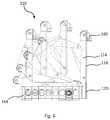
- FIG. 1shows a first embodiment of a boat transfer system according to the invention in a retracted position and overhead mounted in a foundation.
- FIG. 2shows the boat transfer system of FIG. 2 with a deployed cradle.
- FIG. 3shows a second embodiment of a boat transfer system according to the invention in a partially retracted position and base mounted on a foundation.
- FIGS. 4 and 5show a third embodiment of a boat transfer system according to the invention.
- FIG. 6shows movement of the third embodiment shown in FIGS. 4 and 5 .
- the inventionrelates to a boat transfer system 10 ; 110 on a floating vessel 30 or similar, and comprises at least one deployment frame 14 ; 114 for deployment of a cradle 12 .
- the deployment frame 14 ; 114is movable in a mainly horizontal direction, and the deployment frame 14 ; 114 is equipped with first upright guides 18 ; 118 for vertical movement of the cradle 12 .
- the cradle 12is further connected to a guide system 22 ; 130 , 132 , 134 for controlled movement of the cradle 12 in the first upright guides 18 ; 118 .
- Two similar systemscan be placed side by side to operate one cradle 12 .
- the boat transfer system 10 ; 110may comprise first upright guides 18 ; 118 and second upright guides 20 ; 120 .
- the deployment frame 14 ; 114is in an inner position in a parked position, and the deployment frame 14 ; 114 is in an outer position in an operational launch position, such that the first upright guides 18 ; 118 is aligned with the second upright guides 20 ; 120 mounted below the first upright guides 18 ; 118 .
- the boat transfer system 10may have the following main components:
- a cradle 12A cradle 12 .
- a deployment frame 14is provided.
- a fixed frame 16attached temporarily or permanently to the ship or vessel 30 .
- Optional guides 18 on hull 34are optionally provided.
- the cradle 12In the stowed position the cradle 12 , attached to the moving deployment frame 14 by guides and hoisting system, is retracted inboard within the fixed frame 16 .
- the deployment frame 14which may also be a cylinder/multi-arm (as seen in FIG. 4-6 ), moves on horizontal guides on the fixed frame 16 until the inner edge of the cradle 12 is just beyond the ship's side 34 .
- the cradle 12is then lowered, for example by a winch attached to the deployment frame 14 , or by other means.
- First upright guides 18 placed vertically on the deployment frame 14control the cradle 12 so that it can be hoisted or lowered, i.e. move vertically, but cannot swing sideways or fore and aft despite rolling or pitching of the ship 30 .
- the guides in all embodimentscan be tracks or similar, but are not shown in detail in the drawings.
- the boat transfer system operatorlowers the cradle 12 into the water to a depth that allows the subject boat (not shown) to enter the open end of the cradle 12 .
- the boat coxthen drives the boat into the cradle 12 to touch the closed far end, keeping power on until the boat transfer system 10 raises the cradle, and with it the boat.
- the cradle 12incorporates one part of the guide system 22 engaging with the deployment frame 14 and optionally with fixed guides 20 attached to the ship in the freeboard region.
- the deployment frame 14controls the vertical movement of the cradle 12 with a guide system and hoisting/lowering system.
- the guides 18 , 20are arranged so that the cradle can only move up and down, and can not swing away from the ship's side 34 under the influence of waves or ship 30 motion or tilt.
- the fixed frame 16attached to the ship 30 , controls the sideways motion of the deployment frame 14 and cradle 12 .
- Guides and an actuating mechanismmove the deployment frame 14 with cradle 12 from the stowed position within the outline of the ship 30 to the deployment position where the inboard face of the cradle 12 is just beyond the ship's side 34 and the first vertical guides 18 on the deployment frame 14 and the second freeboard guides 20 line up.
- the fixed frame 16may be a complete freestanding unit bolted or welded to the ship's deck 32 , an open frame or incorporating a housing to protect the boat transfer system in harsh climates. Or the guiding/traversing elements may be incorporated in the structure of the ship 30 . Steps and ramps may be included for safe movement of personnel.
- the deployment frame 14may be hung from the movable part of the fixed frame 16 ( FIGS. 1 and 2 ) or the guides for the movable element may be fixed directly to, or recessed into, the deck 32 of the ship 30 ( FIG. 3 ).
- the fixed frame 16is overhead mounted to an overlaying structure (not shown) of the ship 30 .
- the third embodiment of the inventionshall now be described with reference to FIGS. 4-6 .
- the third embodimentcan be used similar as disclosed above.
- the boat transfer system 110 according to the third embodiment of the inventionmay have the following main components:
- a foundation or support structure 144is provided.
- a lower arm or boom 142is attached to A lower arm or boom 142 .
- An upper arm or boom 140An upper arm or boom 140 .
- a docking head/latch 160A docking head/latch 160 .
- Wire sheaves 132 , 134are wire sheaves 132 , 134 .
- An upper boom tilt cylinder 152is provided.
- a lower boom tilt cylinder 150is .
- a wire winch/hoisting winch 130A wire winch/hoisting winch 130 .
- Locking pawl(s) 148 for the first upright guides 118Locking pawl(s) 148 for the first upright guides 118 .
- Second upright guides 120as a vertical rail extension element and end stopper.
- a handling unit park end-stopper 146A handling unit park end-stopper 146 .
- the third embodiment of the inventioncomprises cylinder operated multi-arm system with a tiltable lower arm 142 or boom and an upper arm 140 or boom enabling a rail extension element, i.e. the first upright guides 118 , fixed to a deployment frame 114 and the object to be handled (cradle 12 ), to maintain a vertical position throughout the travel from parked to operational position (as seen in FIG. 6 ).
- a rail extension elementi.e. the first upright guides 118
- Thisis done by means of hydraulic cylinders 150 , 152 .
- An integrated rail 126 in the lower arm 142 , and possible wheels attached to the lower most end of the first upright guides 118ensures smooth movement during tilting.
- An end-stopperensures that the first upright guides 118 are aligned with the connecting vertical rail extension element, i.e. the second upright guides 120 , before operation can start. Additional vertical rails can be connected to the bottom of the second upright guides 120 to increase the vertical travel length.
- the cylinder operated multi-arm systemcan be designed as a knuckle boom crane.
- a foundation/support structure 144may be used to support the lower arm or boom 142 and the lower boom tilt cylinder 150 . It can also include foundation for a wire winch 130 and handling unit park end-stopper 146 .
- the cradle 12is connected to the handling unit(s) docking head/latch 160 when handled between park- and launch position, and the wire winch 130 runs in a tension mode to prevent wire slack.
- the load from the cradle 12is handled by the wire winch 130 .
- the wireruns from the wire winch 130 , via the integrated wire sheaves 132 , 134 to the connection point on the object to be handled (cradle 12 ).
- the cradle 12uses the vertical rail on the first upright guides 118 and second upright guides 120 for guidance.
- the first upright guides 118is secured to the lower arm or boom 142 using locking pawl(s) 148 . Similar locking pawl(s) can also be used in the first and second embodiment of the invention.
- the unit 110 as shown in the drawingscan be arranged as a stand-alone unit or in combination with two or more units working together.
- the two wire winches 130can be linked together using a torsion pipe (not shown).
- the cradle 12may be made from steel sections and tubes or other material. It may be of a generalized U-shape, closed at one end, with fendering or perforated walls to suit the particular application. In end elevation, the lower part may be of different shapes either to accommodate unspecified boats or to cradle a specific boat hull form. Or a series of flexible strops within the cradle may be used to locate a boat.
- the systemcan also be used to retrieve persons from the water of from other floating objects that do not fit in the cradle.
- the cradle 12may thus comprise a self-draining rescue net (not shown) stretched across the cradle 12 .
- the self-draining fine net ‘trampoline’can be stretched across the cradle 12 at various heights. Lowered to just below the surface the net can receive swimmers. If it is raised a little above the water survivors can get on to it from rafts without going into the water, and be lifted to deck level or inboard. The aim is to avoid survivors having to climb scrambling nets or be pulled up the ship's side. Ship personnel may go on to the “trampoline” to assist survivors suffering from injuries or hypothermia.
- the location of the boat transfer system on the ship or foundationis not predefined. For example it can be at the side or the stern as suits the ship and the application.
- empty boatscan be extracted endwise from the stowed cradle and parked on deck, freeing the system to take up the next boat.
- the boat transfer system controlsmay be local or remote. Safety and locking devices can be incorporated to ensure that all phases of the operation are under full control.
Landscapes
- Engineering & Computer Science (AREA)
- Mechanical Engineering (AREA)
- Ocean & Marine Engineering (AREA)
- Combustion & Propulsion (AREA)
- Chemical & Material Sciences (AREA)
- Load-Engaging Elements For Cranes (AREA)
- Ship Loading And Unloading (AREA)
- Separation Using Semi-Permeable Membranes (AREA)
- Two-Way Televisions, Distribution Of Moving Picture Or The Like (AREA)
- Container, Conveyance, Adherence, Positioning, Of Wafer (AREA)
- Jib Cranes (AREA)
- Attitude Control For Articles On Conveyors (AREA)
- Packaging Of Special Articles (AREA)
- Specific Conveyance Elements (AREA)
Abstract
Description
Claims (10)
Applications Claiming Priority (3)
| Application Number | Priority Date | Filing Date | Title |
|---|---|---|---|
| NO20161990ANO20161990A1 (en) | 2016-12-15 | 2016-12-15 | Boat transfer system |
| NO20161990 | 2016-12-15 | ||
| PCT/NO2017/050329WO2018111118A1 (en) | 2016-12-15 | 2017-12-15 | Boat transfer system |
Publications (2)
| Publication Number | Publication Date |
|---|---|
| US20200108899A1 US20200108899A1 (en) | 2020-04-09 |
| US11066132B2true US11066132B2 (en) | 2021-07-20 |
Family
ID=62559053
Family Applications (1)
| Application Number | Title | Priority Date | Filing Date |
|---|---|---|---|
| US16/470,428ActiveUS11066132B2 (en) | 2016-12-15 | 2017-12-15 | Boat transfer system |
Country Status (8)
| Country | Link |
|---|---|
| US (1) | US11066132B2 (en) |
| EP (1) | EP3554939B1 (en) |
| CN (1) | CN110382345B (en) |
| DK (1) | DK3554939T3 (en) |
| ES (1) | ES2925910T3 (en) |
| HR (1) | HRP20221108T1 (en) |
| NO (1) | NO20161990A1 (en) |
| WO (1) | WO2018111118A1 (en) |
Families Citing this family (2)
| Publication number | Priority date | Publication date | Assignee | Title |
|---|---|---|---|---|
| CN111846116B (en)* | 2020-07-07 | 2022-06-03 | 中国舰船研究设计中心 | Device and method for quickly and automatically collecting, releasing and transferring small boat |
| US12291316B2 (en)* | 2022-01-19 | 2025-05-06 | William Golden | Shallow water hydraulic boat lift |
Citations (18)
| Publication number | Priority date | Publication date | Assignee | Title |
|---|---|---|---|---|
| US2761571A (en) | 1955-05-19 | 1956-09-04 | Donald T Adams | Marine hoist |
| GB785202A (en) | 1955-05-19 | 1957-10-23 | Donald Thomas Adams | Improvements in or relating to marine hoists |
| GB2012238A (en) | 1978-01-06 | 1979-07-25 | Blehr & Tenvig As | Marine pick-up |
| AU1782683A (en) | 1982-08-09 | 1984-02-16 | Donald Albert Cooper | Marine structure |
| US4797055A (en) | 1986-12-18 | 1989-01-10 | Atlas Marine Technologies | Load moving apparatus |
| WO1989009723A1 (en) | 1987-03-18 | 1989-10-19 | Ships A/S Excelsior | Device for launching and hoisting up a lifeboat, pick-up boat, etc. |
| US4976211A (en) | 1987-08-31 | 1990-12-11 | Reinhardt Lloyd C | Boat launching system |
| WO1999010229A1 (en) | 1997-08-21 | 1999-03-04 | Dwf Products Ltd. | Dual position personal watercraft lift |
| US6003463A (en) | 1997-08-21 | 1999-12-21 | Dwf Products Ltd. | Dual position personal watercraft lift |
| US6591770B1 (en)* | 2000-10-23 | 2003-07-15 | St. Croix Marine Products, Inc. | Boating lift |
| WO2004022421A1 (en) | 2002-09-05 | 2004-03-18 | West Innovation | A cradle for lifting and launching a small watercraft on an exposed marine landing site |
| WO2006120593A1 (en) | 2005-05-06 | 2006-11-16 | Opacmare S.P.A. | Moving gangway for boats with vertical movement |
| US7156036B2 (en)* | 2005-05-13 | 2007-01-02 | Seiple Ronald L | Launch and recovery system |
| JP2007097177A (en) | 2005-09-28 | 2007-04-12 | Xerox Corp | Image forming apparatus with haptic interface |
| US7377720B2 (en)* | 2005-08-18 | 2008-05-27 | Martin E. Romansi | Boat lift |
| NO20111341A1 (en) | 2011-10-03 | 2013-04-04 | Maritime Robotics As | Ceiling device for launching and recording of boats and objects to / from the sea |
| US20150266550A1 (en) | 2014-03-24 | 2015-09-24 | Otto L. Isbill | Davit cradle lift for small boats |
| US20170096202A1 (en) | 2015-10-06 | 2017-04-06 | Dale David Place | Boat Handling Apparatus |
Family Cites Families (10)
| Publication number | Priority date | Publication date | Assignee | Title |
|---|---|---|---|---|
| JPS525760B2 (en)* | 1971-12-30 | 1977-02-16 | ||
| DE9307194U1 (en) | 1993-05-12 | 1993-07-29 | Pfeil Yachten Handelsgesellschaft mbH, 4000 Düsseldorf | Lifting device for dinghies |
| JP4851870B2 (en) | 2006-07-05 | 2012-01-11 | カヤバ システム マシナリー株式会社 | Upper limit position stop mechanism |
| CN201573776U (en)* | 2009-12-25 | 2010-09-08 | 中国舰船研究设计中心 | Concealed telescopic ship boat-handling device |
| WO2012069853A2 (en)* | 2010-11-26 | 2012-05-31 | Divex Limited | Apparatus to launch and recover a boat |
| SE535660C2 (en) | 2011-02-02 | 2012-10-30 | Lifting or carrying device intended for recreational craft | |
| SG195206A1 (en)* | 2011-06-01 | 2013-12-30 | Nadiro As | A launch and retrieval system |
| US9032895B2 (en) | 2012-09-04 | 2015-05-19 | Larry Ray Buck | Protective boat swim-step extension platform |
| CN203450339U (en)* | 2013-09-23 | 2014-02-26 | 江苏佼燕船舶设备有限公司 | Lifting device for horizontally moving rescue boat |
| CN205396449U (en)* | 2016-02-23 | 2016-07-27 | 江阴耐波特船用设备有限公司 | Hydraulic pressure falls arm -type boat lifting frame |
- 2016
- 2016-12-15NONO20161990Apatent/NO20161990A1/ennot_activeApplication Discontinuation
- 2017
- 2017-12-15ESES17881978Tpatent/ES2925910T3/enactiveActive
- 2017-12-15CNCN201780078070.0Apatent/CN110382345B/enactiveActive
- 2017-12-15HRHRP20221108TTpatent/HRP20221108T1/enunknown
- 2017-12-15USUS16/470,428patent/US11066132B2/enactiveActive
- 2017-12-15WOPCT/NO2017/050329patent/WO2018111118A1/ennot_activeCeased
- 2017-12-15DKDK17881978.5Tpatent/DK3554939T3/enactive
- 2017-12-15EPEP17881978.5Apatent/EP3554939B1/enactiveActive
Patent Citations (18)
| Publication number | Priority date | Publication date | Assignee | Title |
|---|---|---|---|---|
| US2761571A (en) | 1955-05-19 | 1956-09-04 | Donald T Adams | Marine hoist |
| GB785202A (en) | 1955-05-19 | 1957-10-23 | Donald Thomas Adams | Improvements in or relating to marine hoists |
| GB2012238A (en) | 1978-01-06 | 1979-07-25 | Blehr & Tenvig As | Marine pick-up |
| AU1782683A (en) | 1982-08-09 | 1984-02-16 | Donald Albert Cooper | Marine structure |
| US4797055A (en) | 1986-12-18 | 1989-01-10 | Atlas Marine Technologies | Load moving apparatus |
| WO1989009723A1 (en) | 1987-03-18 | 1989-10-19 | Ships A/S Excelsior | Device for launching and hoisting up a lifeboat, pick-up boat, etc. |
| US4976211A (en) | 1987-08-31 | 1990-12-11 | Reinhardt Lloyd C | Boat launching system |
| US6003463A (en) | 1997-08-21 | 1999-12-21 | Dwf Products Ltd. | Dual position personal watercraft lift |
| WO1999010229A1 (en) | 1997-08-21 | 1999-03-04 | Dwf Products Ltd. | Dual position personal watercraft lift |
| US6591770B1 (en)* | 2000-10-23 | 2003-07-15 | St. Croix Marine Products, Inc. | Boating lift |
| WO2004022421A1 (en) | 2002-09-05 | 2004-03-18 | West Innovation | A cradle for lifting and launching a small watercraft on an exposed marine landing site |
| WO2006120593A1 (en) | 2005-05-06 | 2006-11-16 | Opacmare S.P.A. | Moving gangway for boats with vertical movement |
| US7156036B2 (en)* | 2005-05-13 | 2007-01-02 | Seiple Ronald L | Launch and recovery system |
| US7377720B2 (en)* | 2005-08-18 | 2008-05-27 | Martin E. Romansi | Boat lift |
| JP2007097177A (en) | 2005-09-28 | 2007-04-12 | Xerox Corp | Image forming apparatus with haptic interface |
| NO20111341A1 (en) | 2011-10-03 | 2013-04-04 | Maritime Robotics As | Ceiling device for launching and recording of boats and objects to / from the sea |
| US20150266550A1 (en) | 2014-03-24 | 2015-09-24 | Otto L. Isbill | Davit cradle lift for small boats |
| US20170096202A1 (en) | 2015-10-06 | 2017-04-06 | Dale David Place | Boat Handling Apparatus |
Non-Patent Citations (1)
| Title |
|---|
| Extended European Search Report for Application 17881978.5-1015 / 3554939 PCT/NO2017050329, Applicant: Kongsberg Maritime CM AS, dated Jul. 24, 2020. |
Also Published As
| Publication number | Publication date |
|---|---|
| US20200108899A1 (en) | 2020-04-09 |
| EP3554939A1 (en) | 2019-10-23 |
| EP3554939A4 (en) | 2020-08-26 |
| DK3554939T3 (en) | 2022-09-19 |
| WO2018111118A1 (en) | 2018-06-21 |
| CN110382345B (en) | 2021-10-22 |
| CN110382345A (en) | 2019-10-25 |
| HRP20221108T1 (en) | 2022-11-25 |
| ES2925910T3 (en) | 2022-10-20 |
| EP3554939B1 (en) | 2022-06-15 |
| NO20161990A1 (en) | 2018-06-18 |
Similar Documents
| Publication | Publication Date | Title |
|---|---|---|
| US11667355B2 (en) | System and method for launch and recovery of a marine vessel | |
| US8127388B2 (en) | Gangway apparatus | |
| US6152065A (en) | Apparatus for launching and recovery of boats | |
| EP3992368B1 (en) | Jack-up platform with receiving space for a barge and method for offshore installation of a wind turbine | |
| WO2016116771A1 (en) | Multifunctional aft door | |
| US9908590B2 (en) | Aqua lift | |
| KR20220050793A (en) | Boat launch and recovery platform and associated method of launching and recovering | |
| US8156886B2 (en) | Device, system, structure, method, computer program product and control system | |
| US11066132B2 (en) | Boat transfer system | |
| US8631752B2 (en) | Tender stowage method and apparatus | |
| EP2218671A1 (en) | Device for transferring objects at sea | |
| CA2235985C (en) | Dual position personal watercraft lift | |
| EP1268267B1 (en) | A floating arrangement and methods related thereto | |
| US5941192A (en) | Ship borne lifts for tenders and methods for using same | |
| JP4568632B2 (en) | Lifting device | |
| NO20180166A1 (en) | Boat transfer system. | |
| CN114408761A (en) | A kind of navigation mark recovery hoisting device and method | |
| HRP970121A2 (en) | Hydraulic and gravity davit | |
| JP2698736B2 (en) | Port ladder equipment | |
| KR20160146388A (en) | Lifeboat launching device | |
| SU755680A1 (en) | Apparatus for lifting sunk floating means | |
| CN117262123A (en) | Small boat retraction device and small boat retraction method | |
| RU2163878C2 (en) | Ship-raising unit | |
| SU175407A1 (en) | DEVICE FOR LIFTING SMALL SHIPS ON SHIP-BASE DECK AND DOWN THEM TO WATER | |
| JPH03100209A (en) | Riding device for boat |
Legal Events
| Date | Code | Title | Description |
|---|---|---|---|
| FEPP | Fee payment procedure | Free format text:ENTITY STATUS SET TO UNDISCOUNTED (ORIGINAL EVENT CODE: BIG.); ENTITY STATUS OF PATENT OWNER: LARGE ENTITY | |
| AS | Assignment | Owner name:KONGSBERG MARITIME CM AS, NORWAY Free format text:CHANGE OF NAME;ASSIGNOR:ROLLS-ROYCE MARINE AS;REEL/FRAME:049564/0514 Effective date:20190523 | |
| AS | Assignment | Owner name:KONGSBERG MARITIME CM AS, NORWAY Free format text:ASSIGNMENT OF ASSIGNORS INTEREST;ASSIGNORS:DE JONGH, MARTIJN;FYLLING EIDE, LARS;SIGNING DATES FROM 20190709 TO 20190916;REEL/FRAME:050746/0667 | |
| STPP | Information on status: patent application and granting procedure in general | Free format text:NON FINAL ACTION MAILED | |
| STPP | Information on status: patent application and granting procedure in general | Free format text:RESPONSE TO NON-FINAL OFFICE ACTION ENTERED AND FORWARDED TO EXAMINER | |
| STPP | Information on status: patent application and granting procedure in general | Free format text:NOTICE OF ALLOWANCE MAILED -- APPLICATION RECEIVED IN OFFICE OF PUBLICATIONS | |
| AS | Assignment | Owner name:KONGSBERG MARITIME AS, NORWAY Free format text:MERGER;ASSIGNOR:KONGSBERG MARITIME CM AS;REEL/FRAME:056558/0551 Effective date:20210107 | |
| STPP | Information on status: patent application and granting procedure in general | Free format text:PUBLICATIONS -- ISSUE FEE PAYMENT RECEIVED | |
| STPP | Information on status: patent application and granting procedure in general | Free format text:PUBLICATIONS -- ISSUE FEE PAYMENT VERIFIED | |
| STCF | Information on status: patent grant | Free format text:PATENTED CASE | |
| MAFP | Maintenance fee payment | Free format text:PAYMENT OF MAINTENANCE FEE, 4TH YEAR, LARGE ENTITY (ORIGINAL EVENT CODE: M1551); ENTITY STATUS OF PATENT OWNER: LARGE ENTITY Year of fee payment:4 |