US11065461B2 - Implantable power adapter - Google Patents
Implantable power adapterDownload PDFInfo
- Publication number
- US11065461B2 US11065461B2US16/504,623US201916504623AUS11065461B2US 11065461 B2US11065461 B2US 11065461B2US 201916504623 AUS201916504623 AUS 201916504623AUS 11065461 B2US11065461 B2US 11065461B2
- Authority
- US
- United States
- Prior art keywords
- energy
- electrode
- housing
- circuit
- implant
- Prior art date
- Legal status (The legal status is an assumption and is not a legal conclusion. Google has not performed a legal analysis and makes no representation as to the accuracy of the status listed.)
- Active
Links
Images


Classifications
- A—HUMAN NECESSITIES
- A61—MEDICAL OR VETERINARY SCIENCE; HYGIENE
- A61N—ELECTROTHERAPY; MAGNETOTHERAPY; RADIATION THERAPY; ULTRASOUND THERAPY
- A61N1/00—Electrotherapy; Circuits therefor
- A61N1/18—Applying electric currents by contact electrodes
- A61N1/32—Applying electric currents by contact electrodes alternating or intermittent currents
- A61N1/36—Applying electric currents by contact electrodes alternating or intermittent currents for stimulation
- A61N1/372—Arrangements in connection with the implantation of stimulators
- A61N1/378—Electrical supply
- A61N1/3787—Electrical supply from an external energy source
- A—HUMAN NECESSITIES
- A61—MEDICAL OR VETERINARY SCIENCE; HYGIENE
- A61N—ELECTROTHERAPY; MAGNETOTHERAPY; RADIATION THERAPY; ULTRASOUND THERAPY
- A61N1/00—Electrotherapy; Circuits therefor
- A61N1/18—Applying electric currents by contact electrodes
- A61N1/32—Applying electric currents by contact electrodes alternating or intermittent currents
- A61N1/36—Applying electric currents by contact electrodes alternating or intermittent currents for stimulation
- A61N1/372—Arrangements in connection with the implantation of stimulators
- A61N1/37211—Means for communicating with stimulators
- A—HUMAN NECESSITIES
- A61—MEDICAL OR VETERINARY SCIENCE; HYGIENE
- A61B—DIAGNOSIS; SURGERY; IDENTIFICATION
- A61B5/00—Measuring for diagnostic purposes; Identification of persons
- A61B5/0002—Remote monitoring of patients using telemetry, e.g. transmission of vital signals via a communication network
- A61B5/0031—Implanted circuitry
Definitions
- the present disclosurerelates generally to the field of implantable devices, and in particular, to a power adapter configured to be used with an implant.
- Some known implantable devicesreceive power and/or energy by transcutaneously applying low frequency electrical current, similar to the transcutaneous energy transfer and application used in some known devices for delivering transcutaneous electrical stimulation.
- low frequenciescan cause pain, muscle contraction, discomfort, and other undesirable sensations to a subject when applied to a body of the subject.
- Sensitivitye.g., of a body
- an apparatusin some embodiments, includes a housing and a circuit at least partially disposed in the housing.
- the housingcan be configured to be coupled to an implantable electrical conductor for disposition in a body.
- the circuitcan be configured to be electrically connected to a pick-up electrode of the implantable electrical conductor when the housing is coupled to the implantable electrical conductor.
- the circuitis configured to (1) receive, transcutaneously from a power supply, a first energy, (2) convert the first energy to a second energy, and (3) transmit, to the pick-up electrode, the second energy such that the implantable electrical conductor can apply, via a stimulating electrode, the second energy at the second frequency to a region in the body.
- FIG. 1Ais a schematic block diagram depicting a power adapter coupled to an implant, in accordance with an embodiment.
- FIG. 1Bis a schematic block diagram depicting an implant without a power adapter, in accordance with an embodiment.
- FIG. 2is a schematic block diagram depicting a power adapter, in accordance with an embodiment.
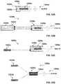
- FIG. 3is a schematic block diagram depicting an example of use of an apparatus in conjunction with a transmitter, in accordance with an embodiment.
- FIG. 4is a flowchart depicting a method of using a power adapter, in accordance with an embodiment.
- FIGS. 5A and 5Bare schematic diagrams depicting an effect of using a power adapter in conjunction with a transmitter, in accordance with an embodiment.
- FIGS. 5C-5Eare waveforms illustrating potential waveforms used with respect to a power adapter, in accordance with an embodiment.
- FIG. 5Fis a graph illustrating the relationship between charge and frequency when applied to an individual, according to an embodiment.
- FIGS. 6A-6Fdepict various views of a power adapter and/or an implant, in accordance with an embodiment.
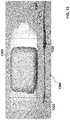
- FIGS. 7A and 7Bdepict a side view and a partial cross-sectional perspective view, respectively, of a power adapter and an implant, in accordance with an embodiment.
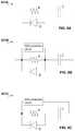
- FIGS. 8A-8Care schematic diagrams depicting circuits of a power adapter, in accordance with various embodiments.
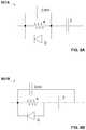
- FIGS. 9A and 9Bare schematic diagrams depicting circuits of a power adapter, in accordance with various embodiments.
- FIG. 11Adepicts a non-rectified waveform (e.g., an alternating current waveform), in accordance with an embodiment.
- a non-rectified waveforme.g., an alternating current waveform
- FIG. 11Bdepicts a one-way rectified waveform, in accordance with an embodiment.
- FIG. 11Cdepicts a two-way rectified waveform, in accordance with an embodiment.
- FIGS. 12A-12Dare schematic diagrams depicting at least a portion of a power adapter, in accordance with various embodiments.
- FIG. 13depicts a transmitter, and a power adapter coupled to an implant, in accordance with an embodiment.
- FIG. 14is a schematic diagram depicting a kit including a power adapter and associated implements, in accordance with an embodiment.
- an apparatusin some embodiments, includes a housing and a circuit at least partially disposed in the housing (e.g., as part of a power adapter).
- the housingcan be configured to be coupled to an implantable electrical conductor for disposition in a body.
- the circuitcan be configured to be electrically connected to a pick-up electrode of the implantable electrical conductor when the housing is coupled to the implantable electrical conductor.
- the circuitWhen the housing is coupled to the implantable electrical conductor and implanted in a body, the circuit is configured to (1) receive, transcutaneously from a power supply, a first energy, (2) convert the first energy to a second energy, and (3) transmit, to the pick-up electrode, the second energy such that the implantable electrical conductor can apply, via a stimulating electrode, the second energy at the second frequency to a region in the body.
- an apparatusin some embodiments, includes a power adapter having a housing and a circuit at least partially disposed in the housing.
- the housingcan be configured to be coupled to an implantable device for disposition in a body.
- the circuitcan be configured to be electrically connected to the implantable device when the housing is coupled to the implantable electrical conductor.
- the circuitcan be configured to (1) receive, transcutaneously from a power supply, a first energy having a first set of characteristics, (2) convert the first energy to a second energy having a second set of characteristics different from the first set of characteristics, and (3) transfer, to the implantable device, the second energy such that the second energy powers the implantable device.
- a methodincludes receiving, transcutaneously and from an electrical pulse generator, first energy having a first set of characteristics.
- the first energyis converted, via a rectification circuit, to a second energy having a second set of characteristics different from the first set of characteristics.
- the second energyis transferred from the rectification circuit to a stimulating electrode of an implantable electrical conductor such that the implantable electrical conductor applies, via the stimulating electrode, the second energy to a target nerve internal to a body.
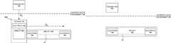
- FIG. 1Ais a schematic block diagram depicting a power adapter 100 coupled to an implant 104 , in accordance with an embodiment.
- the power adapter 100includes a housing 110 , a circuit 120 at least partially disposed in the housing 110 and an electrode 123 .
- the power adapter 100can be configured to be coupled or interconnected to implant 104 such as at and via the housing 110 , as shown in FIG. 1A .
- the power adapter 100can be configured to operate, in conjunction with and when coupled to the implant 104 , in an environment of and internal to a body, such as environment 101 , which can be defined, for example, by a boundary such as skin/partition S, such as shown in FIG. 1A .
- FIG. 1Bis a schematic block diagram depicting the implant 104 without a power adapter being couple thereto (e.g., the power adapter 100 shown in FIG. 1A ).
- the implant 104includes electrodes 19 a and 19 b .
- the power adapter 100when coupled to the implant 104 (e.g., at and/or over electrode 19 a such as shown in FIG. 1A ), can be configured to operate in the environment 101 , in conjunction with the implant 104 and a device such as the transmitter 102 to, for example, enable (e.g., supply power to) the implant 104 to perform or otherwise carry out a medical procedure, task, operation, or measurement in the body.
- the electrode 123can be configured to receive electrical energy from transmitter 102 , the circuit 120 can convert the frequency and/or waveform of the electrical energy, and the power adapter 100 can provide the converted electrical energy to the electrode 19 a , as described in further detail herein.
- the power adapter 100can be configured to receive, from the transmitter 102 and via the electrode 123 , energy E 1 (referred to herein as “first energy”) such as a first form or quantity of energy, power, or signals (collectively, “energy”) having a first characteristic or set of characteristics (e.g., a first frequency, a first waveform, a first burst pattern, and/or the like).
- first energysuch as a first form or quantity of energy, power, or signals (collectively, “energy”) having a first characteristic or set of characteristics (e.g., a first frequency, a first waveform, a first burst pattern, and/or the like).
- the first energy E 1due to the first characteristic(s), may be unsuitable for use in powering and/or to be otherwise provided to or used by the implant 104 .
- the power adapter 100can be configured to transform, rectify, derive, adapt, and/or otherwise convert the first energy E 1 to a second energy E 2 , including a second form or quantity of energy, power, or signals (“collectively, energy”) having a second characteristic or set of characteristics (e.g., a second frequency, a second waveform, a second burst pattern, and/or the like). As shown in FIG.
- the power adapter 100can be configured to convert the first energy E 1 to the second energy E 2 such that the second energy E 2 , due to the second characteristic(s), is suitable for use by the implant 104 , such that the implant 104 is enabled to perform, using the second energy E 2 , the medical procedure in the body (e.g., including providing, via the second energy E 2 , stimulation, activation, or excitation of tissue, nerves, or muscles in the body).
- the power adapter 100can be configured to transfer or input the second energy E 2 to the implant 104 to enable (e.g., powering of, or control over) the implant 104 in performing or otherwise carrying out the medical procedure in the body.
- the circuit 120is electrically coupled to the electrode 19 a (e.g., via a conductor or the like not shown in FIG. 1A ) such that the second energy E 2 that is generated by the circuit 120 is provided as an input to the electrode 19 a.
- the housing 110can be configured to be coupled to the implant 104 for disposition in a body therewith.
- the electrode 123 of the power adapter 100can be configured to receive, transcutaneously with respect to the body, the first energy E 1 (e.g., high frequency electrical bursts, low frequency pulses, etc.) for conversion and transfer to implant 104 for application (e.g., in the form of bursts or pulses, to be used by the implant 104 , etc.), as described herein.
- Skin/partition Scan include, for example, a barrier, partition, skin, and the like, such as of the body of a subject, including, for example, a person, patient, and the like.
- the body of the subjectcan include an (e.g., internal) environment, such as environment 101 .
- the transmitter 102can be or include, for example, an external pulse transmitter (EPT), a power source or supply, an energy source or supply, a voltage source or supply, a (wireless) energy transfer device, a signal transmitter, and/or the like.
- the transmitter 102can be configured to transmit energy (e.g., the first energy E 1 ) into a body of a subject, which can be received, for example, by the power adapter 100 and used in and/or by implant 104 (e.g., when power adapter 100 is coupled to implant 104 ).
- the transmitter 102can be configured to transmit the energy into the body for receipt, or pick-up (e.g., of some portion of the energy), by the power adapter 100 .
- the energyafter being received by the power adapter 100 , can be transferred from the power adapter 100 to the implant 104 (e.g., the second energy E 2 , shown in FIG. 1A ).
- the energycan be converted to a form (e.g., from a first form of energy to a second form of energy) suitable for use in powering the implant 104 , such as to enable the implant 104 to perform a medical procedure in the body, as described herein.
- the power adapter 100can have and/or can be placed in a pass-through configuration and/or state in which the energy received from the transmitter is transferred to the implant without substantially modifying the characteristics of the energy. Accordingly, the second energy E 2 transferred from the power adapter 100 to the implant 104 can have characteristics similar to or different from characteristics of the first energy E 1 received from the transmitter 102 .
- the transmitter 102can be configured to transmit the energy into a body of a subject transcutaneously, at various levels of current, or electrical charge, and at current and/or frequency levels, to avoid causing adverse sensory or motor activation or stimulation (e.g., an undesirable local response) in and by the body.
- the transmitter 102can deliver energy transcutaneously via hydrogel, wetted cloth, and/or other electrodes attached to the skin.
- the transmitter 102can be configured to transmit the energy via output of a time-varying voltage (or electrical potential), current (or electrical charge), or electromagnetic field—at a predetermined frequency or range of frequencies, and with a predetermined waveform.
- the output from the transmitter 102can include, for example, a time-varying flow of electrical charge.
- the time-varying flow of electrical chargecan include, for example, electrical bursts, electrical pulses, and/or the like (“electrical burst(s)” or “burst(s)”), such as in the form of a train or series of high frequency bursts, including, for example, electrical, electromagnetic, and/or magnetic bursts.
- the output of the transmitter 102can include a train or series of low frequency bursts, where each burst includes a single low frequency pulse.
- the output of the transmitter 102can include a train or series of bursts including any suitable combination of one or more low frequency energy bursts and one or more high frequency energy bursts.
- the one or more low frequency energy burstscan have one or more characteristics configured to result in a desirable local response in and by the body such as, for example, increased blood flow within a region of the body adjacent to or relatively near the transmitter 102 , while the one or more high frequency energy bursts can be received by, for example, the power adapter 100 .
- the predetermined frequency or range of frequenciescan include, for example, a frequency or range of frequencies in the range of approximately 10 kilohertz (kHz) to 60 kHz.
- the predetermined frequency or range of frequenciescan otherwise include a frequency or range of frequencies at which the energy output from the transmitter 102 can be applied, such as to a body of a subject, without causing an undesirable response, or stimulation (“response”), such as an undesirable local motor response, in and by the body, such as shown in FIG. 5F .
- the transmitter 102can be configured to transmit the energy (e.g., first energy E 1 ) at a frequency and charge configured to avoid causing a sensation or response in or by the body tissues (e.g., a local response).
- the transmitter 102can be configured to transmit energy (e.g., the first energy E 1 ) at a frequency and charge configured to cause a desirable local response (e.g., increased blood flow or other desired local responses).
- the transmitter 102can be configured to transmit energy (e.g., the first energy E 1 ), in which a first portion of the energy is at a first frequency and/or charge configured to avoid causing a local response and a second portion of the energy is at a second frequency and/or charge configured to cause the desirable local response.
- the transmitter 102can be configured to transmit the first portion of the energy and the second portion of the energy in any suitable combination, pattern, interval, sequence, and/or the like.
- the predetermined waveformcan include, for example, a sinusoidal waveform, a rectangular waveform, a triangular waveform, or any other suitable waveform, such as shown and described with reference to FIGS. 5C-5E .
- the predetermined waveformcan otherwise include any suitable type of waveform.
- Operating parameters by which the transmitter 102 can be configured to transmit the energycan include, for example, pulse width, pulse frequency, current magnitude, current density, power magnitude, power density, and the like.
- the transmitter 102can be configured to transmit the energy by application of the output to a body of a subject at or with respect to a position, region, or location surrounding, encompassing, or adjacent to a position or location at which the power adapter 100 or the implant 104 are disposed (e.g., implanted) in the body, such as shown in FIG. 1A .
- the transmitter 102can be configured to transmit the energy by application of the output to the body, transcutaneously, such as along or with respect to a path (e.g., electrical path, conductive path) at least partially disposed internal to the body, and interconnecting the transmitter 102 , the power adapter 100 , and the implant 104 .
- a pathe.g., electrical path, conductive path
- the pathcan be defined, in part, by the body into which the transmitter 102 is configured to transmit the energy, such as by the portion of the body between the transmitter 102 , power adapter 100 , and implant 104 , such as shown and described with reference to FIG. 3 .
- the implant 104represents an implant such as an implantable device, including, for example, an implantable electrical conductor, and/or the like (“implant” or “implantable device” or “implantable electrical conductor”).
- the implant 104can be configured to be powered by and/or otherwise use energy received from an external device such as an external transmitter or power supply (e.g., transmitter 102 ), via a power adapter (e.g., power adapter 100 ), to perform a medical procedure in a body (e.g., in environment 101 ) of a subject, as described herein.
- the implant 104can include an onboard energy source, energy storage device, and/or the like, such as a battery. Such a battery can, for example, store and/or be recharged by the energy received transcutaneously.
- the implant 104can be or include an implantable electrical conductor, such as of an implantable stimulation device, or stimulator, configured to operate in the body, and to be powered, via the power adapter 100 , by an external device such as the transmitter 102 .
- the implantable stimulation device, or stimulatorcan be or include, for example, a nerve stimulator, an artificial pacemaker, and/or the like.
- the implant 104can be or include an implantable electrical conductor, such as of a fluid conveyance device, or fluid conveyor, such as a pump or compressor (e.g., insulin pump), or a vacuum, suction, or depressurizing device.
- the implant 104can be or include an implantable electrical conductor, such as a sensor, transducer, monitor, and/or recorder, including, for example, an electrocardiography (ECG) sensor, a heart rate monitor, a Holter monitor, and/or the like.
- ECGelectrocardiography
- the implantcan otherwise be or include any suitable type and number of implantable electrical conductors.
- the implant 104includes electrodes 19 a and 19 b , interconnected over conductor 18 .
- the implant 104can include an input and an output, such as at the electrode 19 a and the electrode 19 b , respectively.
- the implant 104can be configured to receive energy at the input (e.g., at the electrode 19 a ), and to provide energy at the output, (e.g., at the electrode 19 b ). Energy can be conveyed between the input (e.g., electrode 19 a ) and the output (e.g., electrode 19 b ) via an implantable electrical conductor (e.g., conductor 18 ) of the implant 104 .
- an implantable electrical conductore.g., conductor 18
- the implant 104can be configured to receive, transcutaneously and at the electrode 19 a , energy from a transmitter such as transmitter 102 .
- the energycan be received, for example, to power the implant 104 , to control the implant 104 (e.g., as in performing a medical procedure), and/or the like.
- the implant 104can be configured to receive energy from the transmitter 102 via the power adapter 100 .
- the power adapter 100can be configured to receive the first energy E 1 (e.g., having a first frequency, waveform and/or other characteristic) from the transmitter, for conversion of the first energy to the second energy E 2 (e.g., having a second frequency, waveform and/or other characteristic), and transfer of the second energy E 2 , from the power adapter 100 and to the implant 104 , such as by input to the implant 104 at the electrode 19 a , such that the implant 104 receives the second energy E 2 (e.g., for output at electrode 19 b ).
- the first energy E 1e.g., having a first frequency, waveform and/or other characteristic
- the second energy E 2e.g., having a second frequency, waveform and/or other characteristic
- the electrode 19 acan receive the second energy E 2 directly.
- the implant 104can be retrofitted and/or adapted to receive the first energy E 1 rather than the second energy E 2 . That is, when the power adapter 100 is connected to the implant 104 , such as shown in FIG. 1A , the power adapter 100 can prevent the electrode 19 a from directly receiving energy.
- the energy output by electrode 19 bcan be detected and/or received by the transmitter 102 (e.g., by a skin electrode (not shown in FIG. 1A or 1B ) to complete an electrical circuit including the transmitter 120 , the housing 110 and the implant 104 .
- the electrodes 19 a and 19 bcan each include one or more electrodes, electrical contacts, electrical terminals, and the like.
- the electrode 19 acan include an input electrode and the electrode 19 b can include an output electrode.
- the electrode 19 acan include an input electrode such as a receiving electrode, a pick-up electrode, and/or the like (referred to herein as “pick-up electrode”).
- the electrode 19 bcan include an output electrode such as a stimulating or stimulation electrode, a stimulation lead, and/or the like (referred to herein as “stimulating electrode” or “stimulation electrode”).
- the electrode 19 acan include or be formed of a material such as a material composed of titanium (Ti), titanium-nitride (TiN), platinum-iridium (Pt—Ir) compound, and/or the like.
- the electrode 19 bcan include or be formed of a material such as a material composed of platinum (Pt), iridium (Ir), a platinum-iridium (Pt—Ir) compound, or alloy, and/or the like.
- the conductor 18can include any suitable electrical conductor, electrical lead, and/or conductive material over which the electrodes 19 a and 19 b can be interconnected.
- the conductor 18can include a path such as a conductive path or an electrical path configured to interconnect the electrodes 19 a and 19 b over the implant 104 .
- the conductor 18can include or be formed of a material such as an inert or non-reactive material, or any other material suitable for use in a body of a subject, in accordance with embodiments described herein.
- the housing 110can be or can include any suitable type of housing or casing.
- the housing 110can include a housing such as an hermetically sealed casing, or can, configured to house or otherwise contain one or more circuits (e.g., circuit 120 ), and, having a feedthrough, inner contact (e.g., electric conductor), one or more mating features (e.g., grip mechanism assembly) configured to electrically and mechanically couple to and make contact with a pick-up electrode (e.g., electrode 19 a of implant 104 ), and a sleeve (e.g., for mechanical and/or electrical protection).
- the housing 110can be configured to at least partially house one or more circuits, including, for example, the circuit 120 .
- the housing 110can be configured to be coupled to an implant such as implant 104 for disposition, with implant 104 (and the circuit 120 ), in a body of a subject.
- the housing 110can be configured to mechanically insulate the circuit 120 from the body, including, for example, from an environment in the body such as environment 101 .
- the housing 110can be configured to insulate the circuit 120 from, for example, an environment such as environment 101 in the body of the subject, such as when the housing 110 is coupled to implant 104 and disposed in environment 101 , such as by implantation with implant 104 in the body.
- the housing 110can include any suitable housing capable of attaching, coupling, connecting, interconnecting, or otherwise being added, mechanically, electrically, and otherwise, to an implant such as implant 104 , as described herein.
- the housing 110can include any suitable type and number of components, such as including resistors, capacitors, transistors, diodes, inductors, an energy source, energy storage device, and/or the like.
- the housing 110does not include an energy source, energy storage device, and/or the like, which can be or include, for example, a battery or other chemical source of energy.
- the housingcan include an energy storage device (e.g., battery, energy storage capacitor, etc.) that can be used to power the implant 104 and/or can be recharged by receiving the transcutaneous transfer of energy, as described herein.
- the housing 110can be or include, for example, a hermetically sealed can configured to at least partially house the circuit 120 .
- the circuit 120can be or include a circuit such as an integrated circuit (IC), and/or the like.
- the circuit 120can be configured to be electrically connected to an implantable device such as the implant 104 when the housing 110 is coupled to the implant 104 , such as at the electrode 19 a .
- the circuit 120can be configured to electrically connect to the implant 104 , when the housing 110 is coupled to the implant 104 , such as at a pick-up electrode (e.g., electrode 19 a ) of the implant 104 , to enable the circuit 120 to provide energy (e.g., transformed power, conditioned signals) to the implant 104 .
- energye.g., transformed power, conditioned signals
- the energycan be provided, by the circuit 120 and to the implant 104 , via input to the implant 104 at the pick-up electrode (e.g., via a conductor or electric interface in electric communication with the electrode 19 a ).
- the circuit 120can be configured to receive the energy (e.g., for conversion of the energy and transfer of the converted energy to implant 104 ) from a transmitter such as transmitter 102 , as described herein.
- the circuit 120can include various components, such as described herein with reference to FIG. 2 .
- the power adapter 100can be configured to be implanted, in a coupled or interconnected state with implant 104 , in a body of a subject.
- the power adapter 100can be configured to be coupled to implant 104 by attachment of the housing 110 over a pick-up electrode (electrode 19 a ) of the implant 104 .
- the power adapter 100can be configured to be retrofit to an existing implant in a body of a subject, such as the implant 104 .
- the power adapter 100can be configured to be mated to the existing implant such as by crimping, or the like.
- operating parametersincluding, for example, stimulation parameters, and the like, can be set (e.g., at transmitter 102 ), as described herein.
- the power adapter 100along with the transmitter 102 and the implant 104 —can be configured for use, such as by the subject of the body (in which the power adapter 100 is implanted with the implant 104 ).
- the power adapter 100can be integral to the implant 104 .
- the power adapter 100can be provided as part of or embedded in the implant 104 , such as in a pre-coupled or -interconnected state with the implant (e.g., via interconnection to electrode 19 a ).
- the functions of the power adapter 100can be part of and/or integrated into the implant. In such implementations, a separate power adapter 100 is not needed and/or used to receive the transcutaneous energy transfer.
- the power adapter 100can be configured to convert the first energy E 1 (e.g., from transmitter 102 ) to the second energy E 2 , for input of the second energy E 2 to the implant 104 to enable the implant 104 in performing a medical procedure.
- the medical procedurecan include, for example, a medical procedure in which the implant 104 is configured to provide stimulation, activation, excitation, and the like (“stimulation”) of tissue, nerves, or muscles in a body of a subject.
- the implant 104can be configured to perform the medical procedure in the body via output of the second energy E 2 at the electrode 19 b .
- the second energy E 2can include, for example, a sequence of low frequency pulses or bursts and/or a sequence of high frequency pulses or bursts.
- the second energy E 2can include, for example, interlaced delivery of low and high frequency energy, stimulation, bursts, and/or pulses.
- the medical procedurecan be performed, for example, to activate a cutaneous receptor, a muscle, and/or a nerve of the body.
- FIG. 2is a schematic block diagram depicting a power adapter 200 , in accordance with an embodiment.
- the power adapter 200includes a housing 210 and a circuit 220 at least partially disposed in the housing 210 .
- the power adapter 200can be configured to be coupled or interconnected to an implant (e.g., the implant 104 ) for disposition in a body, such as to operate in an environment (e.g., the environment 101 ) of and internal to the body.
- the circuit 220when the housing 210 is coupled to an implant (e.g., the implant 104 ) and implanted in a body, can be configured to electrically interconnect (e.g., via an electrode 223 b ) to a stimulating electrode of the implant.
- the power adapter 200can be structurally and/or functionally similar to other power adapters (e.g., the power adapter 100 ) shown and described herein.
- the circuit 220includes a rectification circuit 221 and an electrode 223 a (e.g., pick-up electrode).
- the rectification circuit 221can be or include, for example, a halfwave-rectification circuit or a fullwave-rectification circuit.
- the rectification circuit 221can include a resistor 222 , a diode 224 , and a capacitor 226 .
- the circuitcan include another capacitor and/or an inductor to provide protection at frequencies used with respect to MRI devices.
- the rectification circuit 221can be configured to selectively convert received energy (e.g., received from the transmitter 102 via the electrode 223 a ).
- the rectification circuit 221can be configured to convert first energy by rectification of the first energy to provide second energy (e.g., via the electrode 223 b ).
- the second energycan be substantially positive DC or substantially negative DC.
- the rectification circuit 221can be configured to convert and filter received signals in a manner similar to that of an amplitude modulation (AM) receiver.
- AMamplitude modulation
- the capacitor 226can be or include, for example, a direct current (DC) blocking capacitor.
- the capacitor 226can be configured to maintain a level of charge balance of the rectification circuit 221 .
- the capacitor 226can be configured to provide charge balancing of energy transmitted from the rectification circuit 221 .
- a type or characteristic of the capacitor 226can be chosen, for example, based on a characteristic (e.g., operating condition) such as tissue-electrode capacitance, such as of a pick-up electrode (e.g., electrode 19 a ) and a stimulating electrode (e.g., electrode 19 b ) of the implant 104 , with respect to tissue internal to a body of a subject (e.g., in environment 101 ).
- tissue-electrode capacitancesuch as of a pick-up electrode (e.g., electrode 19 a ) and a stimulating electrode (e.g., electrode 19 b ) of the implant 104
- the capacitor 226can effectively be connected in series with the pick-up electrode and the stimulating electrode.
- the capacitor with the least amount of capacitancedetermines the combined capacitance of the capacitors (e.g., which is substantially equal to the capacitance of the capacitor with the least relative amount of capacitance).
- the capacitor 226can be chosen or configured to have a particular value or measure of capacitance to not decrease the overall capacitance of the path (e.g., interconnecting the capacitor 226 , the pick-up electrode, and the stimulating electrode) based on the effective capacitance of the tissue-electrode capacitance of the pick-up electrode and the stimulating electrode.
- the capacitor 226can be chosen or configured to have a value or measure of capacitance of approximately 4 ⁇ F, or greater.
- the value of the capacitor 226can be chosen or configured based on the tissue-electrode capacitance of the tissue internal to the body and the pick-up electrode (e.g., electrode 19 a ) and the stimulating electrode (e.g., electrode 19 b ) of the implant 104 .
- the capacitor 226can be chosen or configured to have a value or measure of capacitance that does not decrease, but supports and/or maintains an overall capacitance of the conductive path (e.g., the path interconnecting a pick-up electrode with a stimulating electrode) of the implant 104 .
- the diode 224can be or include, for example, a rectifying diode.
- the diode 224can be or include a rectifying diode such as a Schottky diode, a silicone diode, and/or the like.
- a type or characteristic of the diode 224can be chosen, for example, based on a characteristic such as a magnitude of a voltage drop (e.g., in a forward direction) over the diode 224 .
- the type of the diode 224can be chosen to reduce a magnitude of the voltage drop over the diode 224 .
- the type of the diode 224can be chosen to be or include a Schottky diode (e.g., instead of a silicon diode) to reduce the magnitude of the voltage drop over the diode 224 (e.g., compared to that of the silicon diode), and to thereby achieve a higher pick-up ratio (e.g., compared to that of a silicone diode).
- a type of the diode 224can be chosen based on or to facilitate any suitable characteristic, such as amount of leak current, amount of back leak current, a discharge rate (e.g., of capacitor 226 ) between applied electrical bursts, and/or the like.
- pick-up” ratiorefers to the amount of energy received by the implant relative to the amount of energy sent by the external transmitter. For example, a pick-up ratio of 0.5 indicates that the amount of energy received is approximately half the amount of energy sent.
- the resistor 222provides a discharge path (from rectification circuit 221 ) for the capacitor 226 .
- a type or characteristic of the resistor 222can be chosen, for example, based on a characteristic of the rectification circuit 221 including, for example, a discharge path characteristic of the rectification circuit 221 .
- the resistor 222can be chosen to have a measure or value of resistance greater than an effective resistance of the diode 224 , to prevent bypass (e.g., by electrical current) of the diode 224 in use (e.g., of the power adapter 200 with an implant such as implant 104 ).
- a type or characteristic of the resistor 222can be chosen, for example, based on an applied frequency or frequency range of the energy (e.g., electrical signals, electrical bursts) from transmitter 102 , a burst repetition frequency of the applied frequency or frequency range of the energy, a burst duration of the applied frequency or frequency range of the energy, and/or the like.
- the energye.g., electrical signals, electrical bursts
- FIG. 3is a schematic block diagram depicting an example use of a power adapter 300 in conjunction with a transmitter 302 , in accordance with an embodiment.
- the power adapter 300includes a housing 310 (labeled “add-on receiver”) and a circuit (not shown) at least partially disposed in the housing 310 .
- the power adapter 300can be structurally and/or functionally similar to other power adapters (e.g., 100 , 200 ) described herein.
- the transmitter 302can be configured to send or otherwise provide energy to power adapter 300 (for powering and/or supplying energy to implant 304 ) via path 303 .
- the electrical pulse generatore.g., transmitter 102 , transmitter 302
- the path 303along which the energy is received, transferred, and applied, can include, for example, a portion of the body of the subject between the transmitter 302 (e.g., at a gel and/or cloth electrode of the transmitter (not shown)) and the power adapter 300 (when disposed with implant 104 in the body).
- the power adapter 300 , the housing 310 , and the circuitcan be structurally and/or functionally similar to the power adapter 100 , the housing 110 , and the circuit 120 , respectively, as described herein.
- the power adapter 300can be configured to be coupled, via the housing 310 , to an implant such as implant 304 for disposition in a body with implant 304 , such as beneath skin and in environment 301 of the body.
- the power adapter 300can be configured to be attached or coupled to implant 304 such that the pick-up electrode of implant 304 is electrically insulated from the environment 301 (e.g., when implant 304 and power adapter 300 are implanted in a body).
- the power adapter 300can be configured to receive energy from the transmitter 302 for conversion and transfer to implant 304 , and application, via a stimulating electrode of implant 304 , to a target site or object in the body.
- the transmitter 302can be structurally and/or functionally similar to the transmitter 102 , as described herein.
- the transmitter 302can include an external transmitter (labeled “transmitter”) and a patch (not shown) including one or more gel electrodes (labeled “gel electrode”).
- the external transmittercan include, for example, a high frequency transmitter.
- the patchcan include, for example, a gel patch, a hydrogel patch, a cloth patch, and/or the like, including, for example, electrodes such as gel electrodes, hydrogel electrodes, cloth electrodes, and/or the like.
- the patchcan include a disposable patch.
- the transmitter 302can be configured to transmit energy transcutaneously into the body of a subject (e.g., for receipt by the circuit disposed in the housing 310 ), such as by application, via the patch, of the output of the transmitter 302 to the body.
- Implant 304can be structurally and/or functionally similar to implant 104 , as described herein.
- implant 304can include an electrical conductor or lead (labeled “lead”), a stimulating electrode (labeled “stimulating electrode”), and a pick-up electrode (not shown), over which the power adapter 300 can be attached or coupled, such as described herein with reference to FIG. 1 , and shown in FIG. 3 .
- the lead of implant 304can include, for example, a conductive path interconnecting the stimulating electrode and the pick-up electrode.
- the lead of implant 304can be or include, for example, an electrical conductor such as a coiled wire (Pt—Ir) conductor disposed within a silicone sheath, or tubing.
- Pt—Ircoiled wire
- the lead of implant 304can be insulated (e.g., from tissue in the environment 301 ) by the silicone tubing and by silicone backfill disposed in and configured to close the tubing at each end.
- Implant 304can be configured to receive, transcutaneously and via the power adapter 300 (e.g., disposed at the pick-up electrode of implant 304 ), energy (e.g., electrical signal, electromagnetic signal, magnetic signal) from the transmitter of the transmitter 302 .
- implant 304can be configured to receive the energy to apply, via the stimulating electrode, a stimulus (e.g., electrical bursts, electrical pulses) to a target site or object in a body of a subject.
- implant 304can include, for example, three or more stimulating electrodes (e.g., such as the electrode 19 b ).
- the power adapter 300can be configured to receive, transcutaneously from the transmitter 302 , transdermal high frequency bursts of energy (e.g., electrical energy).
- the energycan be received at, or can otherwise include, for example, a first frequency of between about 30 kHz and 100 kHz, or greater. In other instances, the first frequency can be between 100 kHz and 3 megahertz (MHz). In yet other instances, the first frequency can be 10 MHz or less and/or any other suitable frequency.
- the received energycan be converted, by the power adapter 300 , to a form suitable for use in providing stimulation, activation, or excitation (e.g., of tissue, nerve, muscle) in a body of a subject.
- the received energycan be converted, by the power adapter 300 , to a second energy (e.g., stimulation current) having a second frequency less than the first frequency, such as, for example about 1 kHz.
- the second frequencycan be between 1 kHz and 10 kHz.
- the second frequencycan be between 500 Hz and 30 kHz.
- the energy conversioncan include, for example, rectification and charge balancing via the power adapter 300 .
- the converted energycan be transferred, from the power adapter 300 to a stimulating electrode of the implant 304 , for application to a target in the body (e.g., nerve) at the stimulating electrode.
- the implant 304can be or include a lead such as a flexible electrical conductor having a length of approximately 15 cm and a diameter of approximately 1.2 mm.
- the stimulating electrode of the implant 304can be positioned at or near a target object in the body, such as a nerve, or the like.
- the pick-up electrode of the implant 304can be covered by attachment of the power adapter 300 to the end of the implant 304 at which the pick-up electrode is disposed.
- the target objectcan include any suitable point, region, or part of interest, such as a nerve (e.g., peroneal nerve, peripheral nerve, etc.).
- the implant 304can include, for example, one or more stimulating electrodes having dimensions in the range of approximately 1 mm in length.
- the stimulating electrodescan be spaced along the lead of the implant 304 at a spacing of approximately 1 mm apart.
- one or more of the stimulating electrodes of the implant 304can be manufactured or assembled by coiling of an electrical conductor (e.g., the lead of the implant 304 ) on the outside of the silicone tubing (e.g., silicone sheath) and at the end of the lead, such as shown in FIG. 3 .
- a conductive surface of the stimulating electrodee.g., at the stimulation end of the implant 304
- the implant 304can include, for example, an anchor (e.g., hook, tines) having a diameter of approximately 1.5 mm.
- the anchorcan be configured to fix the implant 304 in position, or otherwise prevent lead migration in the environment 301 upon implantation and positioning of the implant 304 with the power adapter 300 in a body of a subject.
- the anchorcan include a silicone anchor having four prongs or hooks, and can be disposed at the stimulation end of the implant 104 .
- the transmitter 302can optionally be configured to be used or programmed for use via software (e.g., residing on a device external to the transmitter).
- the softwarecan reside or otherwise be hosted on any suitable type of compute device (e.g., mobile device, tablet computer, server).
- the softwarecan be executed at a compute device to generate and send signals (e.g., including commands) to the transmitter 302 for execution (e.g., at the transmitter 302 ), and the transmitter 302 can be configured to receive, from the compute device, one or more of the signals, including, for example, a signal corresponding to a command configured to be executed at the transmitter 302 .
- the signalscan include, for example, machine- or processor-readable code and/or instructions configured to be stored on and/or executed at the transmitter 302 .
- the codecan include instructions configured to be executed at the transmitter 302 , such as to set or specify one or more operating parameters, stimulation parameters, and/or the like, of and/or at the transmitter 302 .
- one or more of the operating parameters of the transmitter 302can include a particular stimulation routine to be applied (e.g., via the implant 104 ), a particular stimulation intensity to be applied (e.g., transcutaneously to the body), an applied frequency or frequency range of the energy to be applied, and so on.
- the softwarecan be configured for use, for example, by a user or operator such as a clinician, a patient, and/or the like.
- the software by which the transmitter 302 can optionally be configured to be used or programmed for usecan be stored, for example, at a compute device such as a tablet compute device.
- the compute devicecan be configured to communicate with the transmitter 302 via a communications link such as a Bluetooth Low Energy (BLE) communications link, or the like.
- BLEBluetooth Low Energy
- the softwarecan be configured to enable access to data including, for example, patient demographic information, session data, patient stimulation profiles, and the like.
- the softwarecan reside or otherwise be hosted for use via a smartphone platform (e.g., iOS, Android).
- the softwarecan include, for example, a mobile app.
- the softwarecan be configured to enable, for example, use tracking, system error or fault notification, and/or the like.
- the softwarecan be configured to control various functions of the transmitter 302 , including, for example, selection of a stimulation program or routine (e.g., as pre-defined by a user such as a clinician), stimulation activation and deactivation (e.g., turning the transmitter 302 on and off), increase or decrease (applied) stimulation intensity, and so on.
- the softwarecan be configured to provide (e.g., via a display, transducer such as a speaker) an indication (e.g., visual, auditory) as to operating status, such as with respect to selected stimulation program, selected stimulation intensity level, good or bad electrode connection, among other types of indications of errors or operating status.
- an indicatione.g., visual, auditory
- operating statussuch as with respect to selected stimulation program, selected stimulation intensity level, good or bad electrode connection, among other types of indications of errors or operating status.
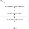
- FIG. 4is a flowchart depicting a method 401 of using a power adapter, in accordance with an embodiment.
- the power adaptercan be structurally and/or functionally similar to any of the power adapters (e.g., 100 , 200 , and/or 300 ) described herein.
- the method 401includes receiving (e.g., via the power adapter 100 , 200 , and/or 300 ), transcutaneously and from an electrical pulse generator (e.g., the transmitter 102 and/or 302 ), first energy at a first frequency and/or first waveform.
- the method 401includes converting, via a rectification circuit (e.g., the rectification circuit 221 ), the first energy to a second energy.
- the second energycan have a second frequency different from the first frequency and/or a second waveform different from the first waveform.
- the method 401includes transferring, from the rectification circuit, the second energy to a stimulating electrode (e.g., the electrode 19 b shown in FIGS. 1A and 1B ) of an implantable electrical conductor (e.g., the implant 104 and/or 304 ) such that the implantable electrical conductor applies, at the second frequency and via the stimulating electrode, the second energy to a target internal to a body (e.g., of a subject).
- the target internal to the bodycan include, for example, a nerve, a region in the body, and/or the like.
- the second energycan be transferred from the rectification circuit (e.g., the rectification circuit 221 ) to a pick-up electrode (e.g., the electrode 19 a ) of the implantable electrical conductor (e.g., the implant 104 ), for subsequent transfer and routing via the implantable electrical conductor (e.g., the conductor 18 of the implant 104 ) to the stimulating electrode (e.g., the electrode 19 b ), and application, at the stimulating electrode, to a target nerve internal to the body.
- the second energycan be transferred from the rectification circuit to the implantable electrical conductor, and in particular, the stimulating electrode, to enable application of the second energy to the target internal to the body.
- the first energycan include, for example, alternating current.
- the second energycan include, for example, pulsating direct current.
- the first frequencycan include, for example, a frequency in the range of about 30 kHz and 100 kHz.
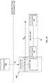
- FIGS. 5A and 5Bare schematic diagrams depicting an effect of using a power adapter 500 in conjunction with a transmitter (e.g., the transmitter 502 b ) and the implant 504 , in accordance with an embodiment.
- the power adapter 500can be structurally and/or functionally similar to other power adapters (e.g., the power adapter 100 , 200 , and/or 300 ) described herein.
- the implant 504can be structurally and/or functionally similar to the implants or implantable electrical conductors (e.g., the implant 104 and/or 304 ) described herein.
- transmitter 502 a(labeled “External Transmitter (low frequency)”) can be configured to apply transcutaneous stimulation (e.g., first energy) via an electrode patch 57 a (e.g., disposed at a skin surface) into a body of a subject.
- the transmitter 502 acan be or include, for example, a low frequency external transmitter, and/or the like, configured to operate in conjunction with the implant 504 (e.g., without the power adapter 500 ).
- the transmitter 502 acan be structurally and/or functionally similar to any of the transmitters (e.g., the transmitter 102 ), as described herein.
- the transmitter 502 acan be configured to transmit the energy by application (e.g., via the electrode patch 57 a ) of the output to the body (e.g., at a skin surface of the body), transcutaneously, such as along or with respect to a path (e.g., electrical path, conductive path) at least partially disposed internal to the body, and interconnecting the transmitter 502 a and the implant 504 .
- the pathcan include, for example, the electrode patch 57 a , a first portion of the body 50 a , the implant 504 (e.g., via the electrodes 59 a and 59 b ), a second portion of the body 50 b , an electrode patch 57 b , and the transmitter 502 a .
- a portion of the applied transcutaneous stimulation(e.g., 10%-20%) can be picked up or received by the implant 504 , at electrode 59 a , and can be transferred and/or routed, to electrode 59 b and along the implant 104 (e.g., via the conductor 18 ).
- the electrode 59 acan include, for example, a pick-up electrode.
- the electrode 59 bcan include, for example, a stimulating electrode.
- the implant 504can include insulation such as a silicone backfill and tubing, disposed about a lead body (e.g., the conductor 18 shown in FIGS. 1A and 1B ) of the implant 504 , such that energy (e.g., electrical pulses received via the electrode 59 a ) can be transmitted efficiently to the conductive surfaces of the stimulation electrode contacts (e.g., of the electrode 59 b ), where the electrical current can then be applied to a target such as a target peripheral nerve, or any other suitable site in the body, as described herein.
- the lead body (e.g., the conductor 18 shown in FIGS. 1A and 1B ) of the implant 504can include, for example, a Pt—Ir lead.
- the energy frequency 51 a at the pick-up electrode and the energy frequency 51 b at the stimulating electrodecan be similar, or substantially equal or identical.
- the waveformcan also be similar, or substantially equal or identical, with the exception of the signal amplitude.
- the transmitter 502 acan be configured to apply and deliver energy transcutaneously at a low applied frequency or frequency range (e.g., below 10 kHz) for stimulation at the low applied frequency at and by the electrode 59 b.
- transmitter 502 b(labeled “External Transmitter (high frequency bursts)”) can be configured to send or transmit first energy (e.g., energy including high frequency bursts) via electrode patch 57 a (e.g., disposed at a skin surface) into a body of a subject, such as described herein.
- the transmitter 502 bcan be or include, for example, a high frequency external transmitter, and/or the like, configured to operate in conjunction with the implant 504 via power adapter 500 .
- the transmitter 502 bcan be structurally and/or functionally similar to transmitters (e.g., the transmitter 102 and/or 302 ) described herein.
- the transmitter 502 bcan be configured to send the first energy at a frequency of approximately 35 kHz-50 kHz, to avoid causing sensation in the body of the subject.
- the transmitter 502 bcan be configured to send the first energy at a frequency to avoid causing direct activation of the nerves about the location of application of the transcutaneous stimulation to the body.
- the transmitter 502 bcan be configured to transmit the energy by application (e.g., via the electrode patch 57 a ) to the body (e.g., at a skin surface of the body), transcutaneously, such as along or with respect to a path (e.g., electrical path, conductive path) at least partially disposed internal to the body, and interconnecting the transmitter 502 b , the power adapter 500 , and the implant 504 .
- the pathcan include, for example, the electrode patch 57 a , a first portion of the body 50 a , the power adapter 500 (e.g., via the electrode 123 and/or 223 a in FIGS. 1 and 2 , respectively), the implant 504 (e.g., via the electrodes 59 a and 59 b ), a second portion of the body 50 b , an electrode patch 57 b , and the transmitter 502 b.
- a portion of the applied transcutaneous stimulation such as between approximately 10%-20%can be picked up by the pick-up electrode of the power adapter 500 , in the form of the first energy 52 a (e.g., having a first frequency and/or having a first waveform) and converted, by a rectification circuit (e.g., the rectification circuit 221 ) of a circuit (e.g., the circuit 120 and/or 220 ) of the power adapter 500 (e.g., at least partially disposed in the housing 510 of the power adapter 500 ), to second energy 52 b (e.g., having a second frequency and/or having a second waveform).
- a rectification circuite.g., the rectification circuit 221
- a circuite.g., the circuit 120 and/or 220
- second energy 52 be.g., having a second frequency and/or having a second waveform
- the second energy 52 bcan include, for example, low frequency bursts, high frequency bursts, and/or the like.
- the second energy 52 bcan be routed to the electrode 59 b for application, via one or more electrodes at or of the electrode 59 b , to a target such as a target peripheral nerve, or any other suitable site in the body, such as to treat pain.
- the second energy 52 bcan include, for example, a sinusoidal waveform, a rectangular waveform, a triangular waveform, or the like.
- the power adapter 500(via the circuit disposed in the housing 510 ) can be configured to operate in a manner similar to that of an AM radio receiver, by demodulating energy including signals such as high frequency bursts (e.g., carrier wave) and detecting the low frequency (e.g., modulated) signal.
- the power adapter 500can be configured to be retrofit and/or adapted for use in or with an implant (e.g., the implant 504 ) normally configured to receive energy at a first frequency (e.g., a low frequency) and/or having a first waveform, such that the implant can receive energy at a second frequency (e.g., low frequency pulses, high frequency bursts) and/or having a second waveform.
- a first frequencye.g., a low frequency
- a second frequencye.g., low frequency pulses, high frequency bursts
- the rectification circuit of the circuit at least partially disposed in housing 510 of the power adapter 500can include a rectifying diode (e.g., the diode 224 ) oriented in a cathodic orientation, such as shown in FIG. 5B , such that cathodic stimulation is provided via the stimulating electrode (of the implant 504 ).
- the rectification circuit of the circuit at least partially disposed in housing 510 of the power adapter 500can include a rectifying diode (e.g., the diode 224 ) oriented in a cathodic orientation such that cathodic stimulation is provided via the stimulating electrode (of the implant 504 ).
- the nerve (e.g., sensory, motor) activation threshold in the cathodic orientationis lower than that of an anodic orientation of the rectifying diode (e.g., the diode 224 ) as it causes more effective depolarization of the cell membrane and subsequent activation of the nerve.
- the housing 510can be or include a hermetically sealed housing made of Titanium.
- the first energy (e.g., current at first frequency) applied by the transmitter 502 bcan be returned, transcutaneously and from the stimulating electrode, to the transmitter in the form of the second energy (e.g., current at second frequency) to complete the electrical circuit.
- the rectifying diode(e.g., the diode 224 ) can be oriented to be connected to the stimulating electrode of the implant 504 .
- the rectifying diode(e.g., the diode 224 ) can be oriented in an anodic orientation such that anodic stimulation is provided via the stimulating electrode (of the implant 504 ).
- FIGS. 5C-5Eare waveforms illustrating potential waveforms used with respect to a power adapter, in accordance with an embodiment.
- waveform 52 ccan be provided similar to first energy 52 a .
- a characteristic of the waveform 52 ccan include, for example, a first frequency and/or waveform, such as a rectangular waveform, or the like.
- Such a waveform 52 ccan be used to provide first energy 52 a to power adapter 500 .
- the power adapter 500can then convert the first energy 52 a to second energy 52 b having a second frequency and/or waveform.
- FIGS. 5D and 5Eshow waveforms 52 d and 52 e , respectively, that are examples of waveforms of second energy 52 b (e.g., as input by the power adapter 500 to the electrode 59 a , and applied by the implant 504 via output at the electrode 59 b ).
- the waveform 52 dis a rectified version of the waveform 52 c of FIG. 5C (e.g., using envelope detection rectification). More specifically, the square wave bursts of the waveform 52 c are rectified to produce the square waveform 52 d , which effectively is a square waveform having a lower frequency than the square wave bursts of the waveform 52 c .
- the waveform 52 ecan be produced using simple rectification of the waveform 52 c .
- the waveform 52 eincludes the positive components of the waveform 52 c , and has removed the negative portions of the waveform 52 c .
- the frequency of the waveform 52 ee.g., of the second energy
- the frequency of the waveform 52 ecan be similar or substantially equal or identical to the frequency of the waveform 52 c (e.g., of the first energy).
- FIG. 5Fis a graph illustrating the relationship between charge per burst and frequency when applied transcutaneously to an individual, according to an embodiment.
- the predetermined frequency or range of frequenciescan include, for example, a frequency or range of frequencies in the range of approximately 10 kHz to 60 kHz.
- the predetermined frequency or range of frequenciescan otherwise include a frequency or range of frequencies and the range of energy and/or charge at which the energy output from the transmitter 102 can be applied, such as to a body of a subject, without causing a response, or stimulation (“response”), such as a local motor response or sensation, in and by the body.
- responsestimulation
- the predetermined frequency or range of frequencies and the amount of energy and/or chargecan be chosen or determined to achieve a targeted response (labeled “Targeted response”) as a function of frequency with respect to a magnitude of the applied energy.
- the magnitude of the applied energycan be specified, for example, such as in terms of a current magnitude, measured in Coulombs.
- FIG. 5Fas the frequency increases, the amount of energy and/or charge that can be applied to the individual without an undesirable local response can also increase.
- Line A illustrated in FIG. 5Fis an example frequency at which the transmitter 502 a of FIG. 5A can transmit the first energy 51 a .
- Line B illustrated in FIG. 5Fis an example frequency at which the transmitter 502 b of FIG.
- the 5Bcan transmit the first energy 52 a to the power adapter 500 .
- a transmittercan be configured to transmit energy that includes any suitable combination of the energy 51 a (e.g., the relatively low frequency) and the energy 52 a (e.g., the relatively high frequency).
- the transmittercan transmit the energy in any suitable pattern, combination, sequence, interlaced or non-interlaced series, time-dependent bursts or pulses, random bursts or pulses, and/or the like.
- the relatively low frequency energycan be configured to result in and/or otherwise cause a desirable local response such as, for example, increased blood flow or other desirable response within a region of the body adjacent and/or near the transmitter, while the relatively high frequency energy can be received by the power adapter and transmitted to the implant, as described above.
- FIGS. 6A-6Fdepict various views of a power adapter 600 and/or an implant 604 , in accordance with an embodiment.
- the power adapter 600can be structurally and/or functionally similar to other power adapters (e.g., 100 , 200 , 300 , and/or 500 ) shown and described herein.
- the implant 604can be structurally and/or functionally similar to other implants (e.g., 104 , 304 , and/or 504 ) shown and described herein.
- the implant 604can include a pick-up electrode 69 a and a stimulating electrode 69 b , such as shown in FIG. 6A .
- the housing 610can be configured to be coupled, for example, to, on, and/or over implant 604 , such that the housing 610 at least partially covers an end of implant 604 , such as shown in FIGS. 6E and 6F .
- the housing 610can be configured to be coupled on and over implant 604 to at least partially cover (e.g., non-hermetically) one or more of the electrodes, such as a pick-up electrode, of the implant 604 , as described herein.
- the housing 610in covering one or more of the electrodes of the implant 604 , can be configured to insulate (e.g., electrically insulate) the one or more (e.g., covered) electrodes from surrounding tissue (e.g., as in environment 101 ) when disposed in a body with implant 604 .
- the one or more covered (e.g., by housing 610 ) electrodes of implant 604can include, for example, a pick-up electrode.
- the housing 610can be configured to be coupled to, on, and over implant 604 with a retainment force of approximately 6.5 Newtons (N).
- the pick-up electrode 69 a of the implant 604is shown in FIG. 6D .
- the power adapter 600can be attached on and over the pick-up electrode of the implant 604 .
- circuit 620can be at least partially disposed in the housing 610 , where the housing 610 includes, for example, a housing (1), configured to function as a pick-up electrode of the power adapter 600 .
- the housing 610can be configured to hermetically seal the circuit 620 inside the housing (1).
- the power adapter 600can include a feed-through conductor (2) through which (converted) energy from the circuit 620 can be transferred to the stimulating electrode of the implant 604 .
- the power adapter 600can include electrical conductors (4).
- the electrical conductors (4)can be, for example, press-fit against the pick-up electrode of the (5) of the implant 604 .
- the housing 610can include a housing configured to couple to the implant 604 , and to fit over the pick-up electrode of the implant 604 , upon coupling of the housing 610 to the implant 604 .
- the housing 610can include a silicone sleeve (3), to electrically insulate the pick-up electrode from surrounding tissue (e.g., when the housing 610 is coupled to the implant 604 and disposed in a body).
- the silicone sleeve (3)can be configured to provide a friction or retainment force to the coupling between the housing 610 and the implant 604 upon coupling of the housing 610 to the implant 604 .
- the silicone sleeve (3)can be configured to apply pressure and friction to the coupling or interface between the power adapter 600 and the implant 604 upon coupling of the housing 610 to the implant 604 .
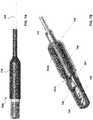
- FIGS. 7A and 7Bdepict a side view and a partial cross-sectional view, respectively, of a power adapter 700 and a portion of an implant 704 , in accordance with an embodiment.
- the power adapter 700can be structurally and/or functionally similar to other power adapters (e.g., 100 , 200 , 300 , 500 , and/or 600 ) shown and described herein.
- the implant 704can be structurally and/or functionally similar to other implants (e.g., 104 , 304 , 504 , and/or 604 ) shown and described herein.
- the implant 704can include a pick-up electrode and a stimulating electrode (not shown), as described above with reference to the implant 604 of FIG. 6A .
- a housing 710 of the power adapter 700can be configured to be coupled, for example, to, on, and/or over implant 704 , such that the housing 710 at least partially covers an end of implant 704 , such as shown in FIGS. 7A and 7B .
- the housing 710can be configured to be coupled on and over implant 704 to at least partially cover (e.g., non-hermetically) one or more of the electrodes, such as a pick-up electrode, of the implant 704 , as described herein.
- the housing 710in covering one or more of the electrodes of the implant 704 , can be configured to insulate (e.g., electrically insulate) the one or more (e.g., covered) electrodes from surrounding tissue (e.g., as in environment 101 ) when disposed in a body with implant 704 .
- the one or more covered (e.g., by housing 710 ) electrodes of implant 704can include, for example, a pick-up electrode.
- the housing 710can be configured to be coupled to, on, and over implant 704 with a retainment force of approximately 6.5 Newtons (N).
- the power adapter 700can be attached on and over a pick-up electrode 705 of the implant 704 .
- a circuit 720can be at least partially disposed in the housing 710 and, in conjunction with the pick-up electrode 705 , can be configured to function as a pick-up electrode of the power adapter 700 .
- the housing 710can be configured to hermetically seal the circuit 720 inside the housing 710 .
- the housing 710can include a first sleeve 703 A and a second sleeve 703 B.
- the first sleeve 703 Acan be, for example, a sleeve, cover, housing, etc. formed from any suitable material.
- the first sleeve 703 Acan be formed from materials such as thermoplastic polyurethane (e.g., Tecothane), polyether ether ketone (PEEK), and/or the like.
- the second sleeve 703 Bcan be a sleeve, cover, housing, etc. formed from any suitable material (e.g., a material similar to or different from the material of the first sleeve 703 A).
- the second sleeve 703 Bcan be formed from a material such as silicone and/or the like.
- At least one of the first sleeve 703 A and/or the second sleeve 703 Bcan be configured to electrically insulate the pick-up electrode 705 from surrounding tissue (e.g., when the housing 710 is coupled to the implant 704 and disposed in a body).
- the first sleeve 703 A and the second sleeve 703 B—alone or in combination—can be configured to provide a friction or retainment force to the coupling between the housing 710 and the implant 704 .
- the sleeve(s) 703 A and/or 703 Bcan be configured to apply pressure and friction to the coupling or interface between the power adapter 700 and the implant 704 upon coupling of the housing 710 to the implant 704 .
- the power adapter 700can include a feed-through conductor 702 through which (converted) energy from the circuit 720 can be transferred to the stimulating electrode of the implant 704 .
- the power adapter 700can further include electrical conductors 706 .
- the electrical conductors 706can be, for example, press-fit against the pick-up electrode 705 of the implant 704 .
- the electrical conductors 706can be electrically connected to the feed-through conductor 702 , thereby allowing the electrical conductors 706 to transmit electric power between the feed-through conductor 702 and the pick-up electrode 705 of the implant 704 .
- a space 707 within the housing 710 at or around an interface between the feed-through conductor 702 and the electrical conductors 706can be filed with epoxy and/or silicone and configured to electrically insulate the interface therebetween. Accordingly, the power adapter 700 can be structurally and/or functionally similar to the power adapter 600 .
- FIG. 8Ais a schematic diagram depicting a circuit 821 A of a power adapter, in accordance with an embodiment.
- the circuit 821 Acan be structurally and/or functionally similar to other circuits or a portion of other circuits (e.g., the circuit 221 ) described herein.
- the circuit 821 Aincludes a capacitor C (e.g., the capacitor 226 ) in series with a resistor R (e.g., the resistor 222 ), which is in parallel with a diode D (e.g., the diode 224 ).
- the diode Dcan include a rectifying diode.
- the capacitor Ccan include a DC blocking capacitor, as described above with respect to capacitor 226 in FIG. 2 .
- the capacitor Ccan be disposed on either side of the diode D.
- the diode Dcan be oriented in cathodic orientation or in anodic orientation.
- a cathode of the diode Dcan be connected to the implant (e.g., at the electrode 19 a ).
- an anode of the diode Dcan be connected to the implant (e.g., at the electrode 19 a of the implant 104 ).
- the resistor Rcan be disposed in parallel to the diode to enable discharge of the capacitor C during positive phase of the pulse (e.g., second energy).
- FIGS. 8B and 8Care schematic diagrams depicting individual circuits 821 B and 821 C, respectively, of a power adapter, in accordance with an embodiment.
- the circuits 821 B and 821 Ccan be configured to provide electrostatic discharge protection (ESD) via an ESD protection circuit.
- ESDelectrostatic discharge protection
- the circuits 821 B and 821 Ccan otherwise be structurally and/or functionally similar to other circuits or a portion of other circuits (e.g., the circuit 221 ) described herein.
- the circuits 821 B and 821 Ccan include a capacitor C (e.g., the capacitor 226 ) in series with a resistor R (e.g., the resistor 222 ) and a diode D (e.g., the diode 224 )—the resistor R is in parallel with the diode D.
- each circuit 821 B and 821 Ccan include an electrostatic discharge (ESD) protection circuit, such as shown in FIG. 8B .
- ESDelectrostatic discharge
- the circuit 821 Bcan include the ESD protection circuit connected in parallel with the diode D (and the resistor R). Accordingly, the ESD protection circuit in the circuit 821 B can be configured to provide protection over the diode D.
- the circuit 821 Ccan include the ESD protection circuit connected in parallel with the diode D and the capacitor C (and the resistor R).
- the ESD protection circuitcan include, for example, a diode such as a Zener diode, a transient volt suppressor (TVS) diode, bidirectional Zener diodes (e.g., two diodes connected in series front to front or back to back) and/or the like.
- the ESD protection circuitcan be configured to reduce an exposure to risk of accidental electrostatic discharge such as during manufacturing and implantation, and further, reduces the need for other ESD protection.
- FIGS. 9A and 9Bare schematic diagrams depicting individual circuits 921 A and 921 B, respectively, of a power adapter, in accordance with an embodiment.
- the circuits 921 A and 921 Bcan be structurally and/or functionally similar to other circuits or a portion of other circuits (e.g., the circuit 221 ) described herein.
- non-rectified current at 64 MHz or 128 MHzwill not activate the nerve (unlike the rectified current), and will not cause any unintended stimulation and/or unpleasant sensation during the MRI procedure.
- the aforementioned frequenciesare MRI frequencies (for 1.5 T and 3.0 T MRI machines respectively), which will bypass the rectifying circuit via the Cmri short circuit (e.g., 921 A and 921 B). Accordingly, at these frequencies, the circuits 921 A and 921 B are configured to not provide rectified pulses to the stimulating electrode of the implant (e.g., the implant 104 ).
- FIGS. 10A and 10Bare schematic diagrams depicting individual circuits 1021 A and 1021 B, respectively, of a power adapter, in accordance with an embodiment.
- the circuits 1021 A and 1021 Bcan be structurally and/or functionally similar to other circuits or a portion of other circuits (e.g., the circuit 221 ) described herein.
- the inductor Lmrican be configured to block higher frequencies, reduce current via the receiver, and can prevent undesired stimulation and also heating (e.g., of the power adapter 100 and/or the implant 104 ) due to the current flow.
- the inductor Lmrican include dimensions of approximately 2.5 mm ⁇ 2.5 mm ⁇ 3.8 mm.
- the aforementioned frequenciesare MRI frequencies that will be blocked by the inductor, which is capable of blocking the MRI frequencies in the circuit 1021 A (e.g., as described above with reference to the circuits 921 A and 921 B). Accordingly, at these frequencies, the circuit 1021 A is configured to not provide pulses to the stimulating electrode of the implant (e.g., the implant 104 ), thereby providing protection to the patient when in an MRI machine.
- the implante.g., the implant 104
- a circuitcan include both an inductor and a capacitor (e.g., a LC circuit).
- the circuit 1021 Bincludes a capacitor Cmri and an inductor Lmri, each of which can be configured to provide magnetic resonance imaging (MRI) protection alone or in combination.
- MRImagnetic resonance imaging
- At least one of the capacitor 1021 A and/or the inductor 1021 Bcan limit, prevent, and/or substantially prevent the circuit 1021 B from providing pulses to the stimulating electrode of the implant (e.g., the implant 104 ), thereby providing protection to the patient when in an MRI machine.
- FIGS. 11A-11Care waveforms illustrating potential waveforms used with respect to a power adapter, in accordance with an embodiment.
- Any of the power adapters described hereincan be used with, can receive, can convert, and/or can output energy having any suitable characteristic or set of characteristics, which can include, for example, one or more characteristics associated with waveform.
- FIG. 11Aillustrates a waveform 1102 a , in accordance with an embodiment.
- the waveform 1102 acan be, for example, a non-rectified waveform associated with and/or otherwise having alternating current.
- a transmittersuch as those described herein can be configured to generate and provide energy (e.g., a first energy) to a power adapter.
- the first energycan have a waveform similar to or substantially the same as the waveform 1102 a shown, for example, in FIG. 11A .
- the power adapter and/or at least a portion thereofcan be configured to rectify the first energy received from the transmitter such that a second energy having a rectified waveform (e.g., a halfwave rectified) waveform or a fullwave rectified waveform) is transferred to, for example, a pick-up electrode of an implant.
- a rectified waveforme.g., a halfwave rectified waveform or a fullwave rectified waveform
- the rectificationcan be, for example, a one-way rectification (also referred to as halfwave-rectification).
- FIG. 11Billustrates a waveform 1102 b resulting from, for example, a one-way or halfwave rectification of the waveform 1102 a .
- the rectificationcan be, for example, a two-way rectification (also referred to as fullwave-rectification).
- FIG. 11Cillustrates a waveform 1102 c resulting from, for example, a two-way or fullwave rectification of the waveform 1102 a.
- FIGS. 12A-12Dare schematic diagrams depicting power adapters, in accordance with various embodiments.
- the power adapters described hereincan be configured to rectify an energy transcutaneously received from a transmitter.
- FIG. 12Aillustrates a power adapter 1200 a coupled to an implant 1204 a .
- the power adapter 1200 a and the implant 1204 acan be similar in at least form and/or function to any of the power adapters and implants, respectively, described in detail herein.
- the power adapter 1200 acan include a circuit 1220 a and one or more electrodes 1223 a that is/are configured to receive energy from the transmitter (e.g., as described above with reference to the electrode 123 and/or 223 a ).
- the power adapter 1200 a and/or the circuit 1220 acan be configured to perform, for example, one-way or halfwave rectification on the energy (e.g., a first energy) received from the transmitter and can provide energy having the one-way of halfwave rectified waveform (e.g., shown in FIG. 11B ) to a pick-up electrode 1205 a of the implant 1204 a (e.g., a second energy).
- FIG. 12Billustrates a power adapter 1200 b coupled to an implant 1204 b , in accordance with an embodiment.
- the power adapter 1200 b and the implant 1204 bcan be similar in at least form and/or function to any of the power adapters and implants, respectively, described in detail herein.
- the power adapter 1200 bcan include a circuit 1220 b , one or more proximal electrodes 1223 b , and a distal electrode 1228 b .
- the electrodes 1223 b and 1228 bcan be configured to receive energy from the transmitter, as described in detail above. In the embodiment shown in FIG.
- the power adapter 1200 bcan be configured as a lead or the like having the circuit 1220 b disposed at or near the proximal end and the distal electrode 1228 b disposed at or near the distal end.
- the power adapter 1200 b and/or the circuit 1220 bcan be configured to perform, for example, two-way or full-wave rectification on the energy (e.g., a first energy) received from the transmitter and can provide the two-way or fullwave rectified energy (e.g., a second energy) to a pick-up electrode of the implant 1204 b .
- the energye.g., a first energy
- the two-way or fullwave rectified energye.g., a second energy
- the proximal electrode 1223 b and the distal electrode 1228 bcan be in electrical communication with the transmitter and configured to transfer energy therebetween (e.g., via two electrical connections, wires, interconnects, etc.).
- the circuit 1220 bcan include, for example, two or more diodes that can enable the power adapter 1200 b and/or the circuit 1220 b to perform the two-way or fullwave rectification on the energy received from the transmitter (e.g., a first energy).
- the power adapter 1200 bcan be configured to provide two-way or fullwave rectified energy to a pick-up electrode 1205 b of the implant 1204 b (e.g., a second energy).
- FIG. 12Cillustrates a power adapter 1200 c coupled to an implant 1204 c , in accordance with an embodiment.
- the power adapter 1200 cincludes a circuit 1220 c and a distal electrode 1228 c at or near the distal end of the power adapter 1200 c and a proximal electrode 1223 c at or near the proximal end of the power adapter 1200 c .
- the power adapter 1200 ccan be similar in at least function to the power adapter 1200 b and, as such, can be configured to provide two-way of fullwave rectified energy to a pick-up electrode of the implant 1204 c .
- providing the circuit 1220 c at or near the distal end of the power adapter 1200 ccan allow for a single electrical connection between the proximal electrode 1223 c and the distal electrode 1228 c (e.g., rather than two electrical connections, as shown in FIG. 12B ).
- FIG. 12Dillustrates a power adapter 1200 d coupled to an implant 1204 d , in accordance with an embodiment.
- the power adapter 1200 dincludes a circuit 1220 d and a distal electrode (not shown in FIG. 12D ) at or near the distal end of the power adapter 1200 d , as described above with reference to the power adapter 1200 c shown in FIG. 12C .
- the power adapter 1200 dcan include a pair of proximal electrodes 1223 d at or near the proximal end of the power adapter 1200 d .
- the power adapter 1200 dcan be similar in at least function to the power adapter 1200 b and/or 1200 c and, as such, can be configured to provide two-way rectified energy to a pick-up electrode of the implant 1204 d .
- including various arrangements of one or more proximal electrodescan allow the power adapter 1200 d to be used with transmitters having various shapes and/or sizes.
- FIG. 13illustrates a power adapter 1300 coupled to an implant 1304 , and a transmitter 1302 configured to provide energy transcutaneously to the power adapter 1300 , in accordance with an embodiment.
- the power adapter 1300 shown in FIG. 13can be configured to perform two-way rectification on the energy received from a transmitter 1302 .
- the power adapter 1300can be configured as a lead or the like that can be coupled to the implant 1304 as described in detail above.
- the power adapter 1300can be configured as a lead having a proximal electrode 1323 disposed at or near a proximal end of the lead and a circuit 1320 at or near a distal end of the lead.
- the leadcan have a length of about 7.0 centimeters (cm). In other embodiments, the lead can be longer than 7.0 cm or can be shorter than 7.0 cm. In some embodiments, the length of the lead and/or power adapter 1300 can be at least partially based on a size and/or shape of the transmitter 1302 used therewith. For example, as shown in FIG. 13 , the arrangement of the power adapter 1300 can be such that the proximal electrode 1323 is at least partially aligned with a first patch, a first side, and/or other suitable portion (e.g., a first portion) of the transmitter 1302 and the circuit 1320 and/or an electrode of the circuit 1320 (not shown in FIG.
- the power adapter 1300 , the transmitter 1302 , and a portion of the body disposed therebetweencan form a circuit and/or at least a portion of a circuit, thereby allowing the power adapter 1300 to perform two-way rectification on the energy (e.g., a first energy) received from the transmitter 1302 .
- the power adapter 1300can be configured to provide two-way rectified energy (e.g., a second energy) to the implant 1304 , as described in detail herein.
- two-way rectified energye.g., a second energy
- the implantcan be structurally and/or functionally similar to other implants (e.g., 104 , 304 , 504 , and/or 604 ) shown and described herein. While the kit 1405 is shown as including seven or more discrete devices, other arrangements and/or configurations can include any number of devices and/or implements, in accordance with embodiments of the present disclosure
- the kit 1405represents a tool set including various implements and tools by which to facilitate disposition of the implant in a body of a subject.
- the lead adaptercan include a lead adapter configured to couple the implant (e.g., 104 , 304 , 504 , and/or 604 ) to a transmitter (e.g., transmitter 102 ) such as during an intraoperative implantation procedure.
- the implantcan include electrodes or probes, and be provided with an energy (e.g., signal, power) input end (e.g., at pick-up electrode) and an energy (e.g., signal, power) output end (e.g., at stimulating electrode, transducing end, sensing end), such as described herein.
- the implantcan be provided in a loading or deployment device, or loader, configured to facilitate implantation of the implant in a body.
- the introducer setcan include, for example, an incision-forming tool, a hollow tube (e.g., through which to dispose the power adapter and the implant in a body of a subject), and a seal.
- the introducer setcan include a trocar including an obturator, a tube such as a cannula, and a medical seal.
- the tunneling needle and the tunneling needle styletcan include a tunneling needle configured to facilitate access to a body, such for subsequent implantation of the implant (e.g., and the power adapter) in the body.
- the anchorcan include, for example, a silicon anchor.
- the anchorcan otherwise include an anchor formed of any suitable material, such as a non-reactive or inert material, and the like.
- the anchorcan be configured to fix the implant (e.g., along with the power adapter) in position in a body when disposed in the body.
- the anchorcan include a 4-pronged anchor configured to prevent or reduce lead migration after implantation.
- the kit 1405can otherwise include any other suitable tool or implement for facilitating access to a body of a subject, and disposition (e.g., via implantation) of the power adapter and the implant in the body, in accordance with embodiments disclosed herein.
- the kit 1405can include tools and implements (provided and supplied in various conditions) such as listed in Table 1, below.
- references in the specification to “one embodiment,” “an embodiment,” “an example embodiment,” or the like,indicate that the embodiment described can include one or more particular features, structures, or characteristics, but it shall be understood that such particular features, structures, or characteristics may or may not be common to each and every disclosed embodiment disclosed herein. Moreover, such phrases do not necessarily refer to any one particular embodiment per se. As such, when one or more particular features, structures, or characteristics is described in connection with an embodiment, it is submitted that it is within the knowledge of those skilled in the art to affect such one or more features, structures, or characteristics in connection with other embodiments, where applicable, whether or not explicitly described.
- the terms “about” and/or “approximately” when used in conjunction with values and/or rangesgenerally refer to those values and/or ranges near to a recited value and/or range. In some instances, the terms “about” and “approximately” may mean within ⁇ 10% of the recited value. For example, in some instances, “approximately a diameter of an instrument” may mean within ⁇ 10% of the length of the instrument. The terms “about” and “approximately” may be used interchangeably. Similarly, the term “substantially” when used in conjunction with physical and/or geometric feature(s), structure(s), characteristic(s), relationship(s), etc.
- a first quantity that is described as being “substantially equal” to a second quantityis intended to convey that, although equality may be desirable, some variance can occur. Such variance can result from manufacturing tolerances, limitations, approximations, and/or other practical considerations.
- the specific configurations of the various componentscan also be varied.
- the size and specific shape of the various componentscan be different from the embodiments shown, while still providing the functions as described herein. More specifically, the size and shape of the various components can be specifically selected for a desired or intended usage.
- the size, shape, and/or arrangement of the embodiments and/or components thereofcan be adapted for a given use unless the context explicitly states otherwise.
Landscapes
- Health & Medical Sciences (AREA)
- Engineering & Computer Science (AREA)
- Biomedical Technology (AREA)
- Nuclear Medicine, Radiotherapy & Molecular Imaging (AREA)
- Radiology & Medical Imaging (AREA)
- Life Sciences & Earth Sciences (AREA)
- Animal Behavior & Ethology (AREA)
- General Health & Medical Sciences (AREA)
- Public Health (AREA)
- Veterinary Medicine (AREA)
- Electrotherapy Devices (AREA)
Abstract
Description
| TABLE 1 |
| Tools and Implements |
| Number | ||
| Components | included | Sterile |
| Implantable Lead (StimRouter Lead in | 1 | Yes |
| Stimulation Probes | 2 | Yes |
| Stimulation Cables (yellow) | 2 | Yes |
| Introducer Set 9 | 1 | |
| Lead Adapter | ||
| 1 | ||
| Tunneling Needle | ||
| 1 | Yes | |
| 1 | Yes | |
| Pack of 4 | 1 | No |
| Gel Electrode Cable (black) | 1 | No |
| 1 | No | |
Claims (30)
Priority Applications (8)
| Application Number | Priority Date | Filing Date | Title |
|---|---|---|---|
| US16/504,623US11065461B2 (en) | 2019-07-08 | 2019-07-08 | Implantable power adapter |
| JP2021566334AJP2022540285A (en) | 2019-07-08 | 2020-07-08 | Apparatus and method for providing electrical energy to a subject |
| CA3139126ACA3139126A1 (en) | 2019-07-08 | 2020-07-08 | Apparatus and methods for providing electric energy to a subject |
| AU2020311913AAU2020311913A1 (en) | 2019-07-08 | 2020-07-08 | Apparatus and methods for providing electric energy to a subject |
| PCT/US2020/041234WO2021007340A1 (en) | 2019-07-08 | 2020-07-08 | Apparatus and methods for providing electric energy to a subject |
| EP20837675.6AEP3996798B1 (en) | 2019-07-08 | 2020-07-08 | Apparatus for providing electric energy to a subject |
| US17/379,220US11890485B2 (en) | 2019-07-08 | 2021-07-19 | Implantable power adapter |
| US18/410,217US20240399159A1 (en) | 2019-07-08 | 2024-01-11 | Implantable power adapter |
Applications Claiming Priority (1)
| Application Number | Priority Date | Filing Date | Title |
|---|---|---|---|
| US16/504,623US11065461B2 (en) | 2019-07-08 | 2019-07-08 | Implantable power adapter |
Related Child Applications (1)
| Application Number | Title | Priority Date | Filing Date |
|---|---|---|---|
| US17/379,220DivisionUS11890485B2 (en) | 2019-07-08 | 2021-07-19 | Implantable power adapter |
Publications (2)
| Publication Number | Publication Date |
|---|---|
| US20210008376A1 US20210008376A1 (en) | 2021-01-14 |
| US11065461B2true US11065461B2 (en) | 2021-07-20 |
Family
ID=74101469
Family Applications (3)
| Application Number | Title | Priority Date | Filing Date |
|---|---|---|---|
| US16/504,623ActiveUS11065461B2 (en) | 2019-07-08 | 2019-07-08 | Implantable power adapter |
| US17/379,220Active2040-06-18US11890485B2 (en) | 2019-07-08 | 2021-07-19 | Implantable power adapter |
| US18/410,217PendingUS20240399159A1 (en) | 2019-07-08 | 2024-01-11 | Implantable power adapter |
Family Applications After (2)
| Application Number | Title | Priority Date | Filing Date |
|---|---|---|---|
| US17/379,220Active2040-06-18US11890485B2 (en) | 2019-07-08 | 2021-07-19 | Implantable power adapter |
| US18/410,217PendingUS20240399159A1 (en) | 2019-07-08 | 2024-01-11 | Implantable power adapter |
Country Status (1)
| Country | Link |
|---|---|
| US (3) | US11065461B2 (en) |
Cited By (1)
| Publication number | Priority date | Publication date | Assignee | Title |
|---|---|---|---|---|
| US11890485B2 (en) | 2019-07-08 | 2024-02-06 | Bioness Inc. | Implantable power adapter |
Families Citing this family (4)
| Publication number | Priority date | Publication date | Assignee | Title |
|---|---|---|---|---|
| AU2020353092A1 (en)* | 2019-09-25 | 2022-04-14 | Bionet Sonar | Systems and methods for using ultrasonic waves for wireless powering and communication of a cardiac assist device |
| US11872387B2 (en)* | 2020-07-28 | 2024-01-16 | Saluda Medical Pty Limited | Trial neurostimulation system with a lead adapter |
| US11696683B2 (en)* | 2021-02-10 | 2023-07-11 | International Business Machines Corporation | Medical device system |
| US20230386362A1 (en)* | 2022-05-27 | 2023-11-30 | Stephen Sophorn Lim | Alternative Braille Communication Device |
Citations (274)
| Publication number | Priority date | Publication date | Assignee | Title |
|---|---|---|---|---|
| US3204637A (en) | 1963-02-07 | 1965-09-07 | Erich J Frank | Stimulating apparatus |
| US3426748A (en) | 1965-11-23 | 1969-02-11 | Gen Electric | Stimulator analyzer and locater |
| US3494907A (en) | 1967-10-03 | 1970-02-10 | Gaf Corp | Functional polymers of heterocyclic n-vinyl monomers and process of preparing the same |
| US3563968A (en) | 1967-10-03 | 1971-02-16 | Gaf Corp | Process for the preparation of functional polymers from n-vinyl pyrrolidone |
| US3796221A (en) | 1971-07-07 | 1974-03-12 | N Hagfors | Apparatus for delivering electrical stimulation energy to body-implanted apparatus with signal-receiving means |
| US4269198A (en) | 1979-12-26 | 1981-05-26 | Medtronic, Inc. | Body implantable lead |
| US4271847A (en) | 1979-06-28 | 1981-06-09 | Medtronic, Inc. | Temporary adjustable bipolar lead |
| US4479500A (en) | 1982-09-16 | 1984-10-30 | Medtronic, Inc. | Pacing lead with A-V distance adapter |
| US4506673A (en) | 1982-10-18 | 1985-03-26 | Rorer Group Inc. | Therapeutic treatment within joint capsules of the body |
| US4515167A (en) | 1983-02-28 | 1985-05-07 | Hochman Joel S | Device for the development, training and rehabilitation of the pubococcygeal and related perineal musculature of the female |
| US4559951A (en) | 1982-11-29 | 1985-12-24 | Cardiac Pacemakers, Inc. | Catheter assembly |
| US4574814A (en) | 1981-07-31 | 1986-03-11 | Cardiofrance-Compagnie Francaise D'electrocardiologie | Sliding coaxial probe for a pacemaker |
| US4658835A (en) | 1985-07-25 | 1987-04-21 | Cordis Corporation | Neural stimulating lead with fixation canopy formation |
| US4664120A (en) | 1986-01-22 | 1987-05-12 | Cordis Corporation | Adjustable isodiametric atrial-ventricular pervenous lead |
| US4702732A (en) | 1984-12-24 | 1987-10-27 | Trustees Of Boston University | Electrodes, electrode assemblies, methods, and systems for tissue stimulation and transdermal delivery of pharmacologically active ligands |
| US4917104A (en) | 1988-06-10 | 1990-04-17 | Telectronics Pacing Systems, Inc. | Electrically insulated "J" stiffener wire |
| US4989617A (en) | 1989-07-14 | 1991-02-05 | Case Western Reserve University | Intramuscular electrode for neuromuscular stimulation system |
| US5012806A (en) | 1986-11-11 | 1991-05-07 | Ferruccio De Bellis | Implantations for cardiac stimulation by pacemaker |
| US5016646A (en) | 1988-11-29 | 1991-05-21 | Telectronics, N.V. | Thin electrode lead and connections |
| US5030457A (en) | 1989-08-28 | 1991-07-09 | Pharmaceutical Delivery Systems, Inc. | Bioerodible polymers useful for the controlled release of therapeutic agents |
| US5217028A (en) | 1989-11-02 | 1993-06-08 | Possis Medical, Inc. | Bipolar cardiac lead with drug eluting device |
| US5231996A (en) | 1992-01-28 | 1993-08-03 | Medtronic, Inc. | Removable endocardial lead |
| US5300107A (en) | 1992-10-22 | 1994-04-05 | Medtronic, Inc. | Universal tined myocardial pacing lead |
| US5324316A (en) | 1991-12-18 | 1994-06-28 | Alfred E. Mann Foundation For Scientific Research | Implantable microstimulator |
| US5330489A (en) | 1992-10-09 | 1994-07-19 | United States Surgical Corporation | Sternum closure buckle |
| US5405367A (en) | 1991-12-18 | 1995-04-11 | Alfred E. Mann Foundation For Scientific Research | Structure and method of manufacture of an implantable microstimulator |
| US5441527A (en) | 1992-02-20 | 1995-08-15 | Amei Technologies Inc. | Implantable bone growth stimulator and method of operation |
| US5545206A (en) | 1994-12-22 | 1996-08-13 | Ventritex, Inc. | Low profile lead with automatic tine activation |
| US5653742A (en) | 1995-09-20 | 1997-08-05 | Cochlear Pty. Ltd. | Use of bioresorbable polymers in cochlear implants and other implantable devices |
| US5769858A (en) | 1995-10-20 | 1998-06-23 | Medtronic, Inc. | Locking stylet for extracting implantable lead or catheter |
| EP0862925A2 (en) | 1997-03-03 | 1998-09-09 | Medtronic, Inc. | Sacral medical electrical lead |
| US5814090A (en) | 1995-06-07 | 1998-09-29 | Angeion Corporation | Implantable medical device having heat-shrink conforming shield |
| WO1998048887A1 (en) | 1997-04-29 | 1998-11-05 | Medtronic, Inc. | Intracardiac defibrillation system |
| US5849033A (en) | 1994-01-21 | 1998-12-15 | Medtronic, Inc. | Temporary medical electrical lead |
| US5861019A (en)* | 1997-07-25 | 1999-01-19 | Medtronic Inc. | Implantable medical device microstrip telemetry antenna |
| US5871531A (en) | 1997-09-25 | 1999-02-16 | Medtronic, Inc. | Medical electrical lead having tapered spiral fixation |
| US5897585A (en) | 1997-12-18 | 1999-04-27 | Medtronic, Inc. | Stretchable pacing lead |
| US5919222A (en) | 1998-01-06 | 1999-07-06 | Medtronic Inc. | Adjustable medical electrode lead |
| US5931864A (en) | 1998-02-20 | 1999-08-03 | Cardiac Pacemakers, Inc. | Coronary venous lead having fixation mechanism |
| US5939453A (en) | 1998-06-04 | 1999-08-17 | Advanced Polymer Systems, Inc. | PEG-POE, PEG-POE-PEG, and POE-PEG-POE block copolymers |
| US5944729A (en) | 1997-12-12 | 1999-08-31 | Scanlan International, Inc. | Vascular occlusion clamp with radiopaque retrieval, identification and marking string |
| US5954759A (en) | 1997-04-21 | 1999-09-21 | Medtronic, Inc. | Fracture resistant medical electrical lead |
| US5968543A (en) | 1996-01-05 | 1999-10-19 | Advanced Polymer Systems, Inc. | Polymers with controlled physical state and bioerodibility |
| US6006122A (en) | 1997-09-25 | 1999-12-21 | Medtronic, Inc. | Medical electrical lead |
| US6083216A (en) | 1999-01-05 | 2000-07-04 | Intermedics Inc. | Bent cardiac lead with shape memory torque coil |
| US6153664A (en) | 1997-04-18 | 2000-11-28 | Cambridge Scientific, Inc. | Bioerodible polymeric semi-interpenetrating network alloys and internal fixation devices made therefrom |
| US6181973B1 (en) | 1999-04-02 | 2001-01-30 | Claudio Ceron | Anchoring structure for implantable electrodes |
| US6214032B1 (en) | 1996-02-20 | 2001-04-10 | Advanced Bionics Corporation | System for implanting a microstimulator |
| US6240322B1 (en) | 1998-11-04 | 2001-05-29 | Cardiac Pacemakers, Inc. | System and apparatus having low profile collapsible tines |
| US6289251B1 (en) | 1999-11-01 | 2001-09-11 | Medtronic, Inc. | High strength medical electrical lead |
| US6304786B1 (en) | 1999-03-29 | 2001-10-16 | Cardiac Pacemakers, Inc. | Implantable lead with dissolvable coating for improved fixation and extraction |
| US6330481B1 (en) | 1999-10-04 | 2001-12-11 | Medtronic Inc. | Temporary medical electrical lead having biodegradable electrode mounting pad |
| US20010051807A1 (en) | 2000-06-12 | 2001-12-13 | Arthrex, Inc. | Expandable tissue anchor |
| US20020007204A1 (en) | 2000-05-17 | 2002-01-17 | Cook Vascular Incorporated | Apparatus for removing an elongated structure implanted in biological tissue |
| US6438428B1 (en) | 1999-10-27 | 2002-08-20 | Axelgaard Manufacturing Co., Ltd. | Electrical stimulation compress |
| US6505074B2 (en) | 1998-10-26 | 2003-01-07 | Birinder R. Boveja | Method and apparatus for electrical stimulation adjunct (add-on) treatment of urinary incontinence and urological disorders using an external stimulator |
| US6505082B1 (en) | 1998-07-22 | 2003-01-07 | Cardiac Pacemakers, Inc. | Single pass lead system |
| US6510347B2 (en) | 2000-08-17 | 2003-01-21 | William N. Borkan | Spinal cord stimulation leads |
| US6517559B1 (en) | 1999-05-03 | 2003-02-11 | O'connell Paul T. | Blood filter and method for treating vascular disease |
| US20030050672A1 (en)* | 2000-03-08 | 2003-03-13 | Kenneth Dahlberg | Manufacturing process in connection with pacers connectors |
| US20030078618A1 (en) | 2001-10-19 | 2003-04-24 | Fey Kate E. | System and method for removing implanted devices |
| US6580949B1 (en) | 1999-07-23 | 2003-06-17 | Terumo Kabushiki Kaisha | Implantable electrode lead |
| US20030139794A1 (en) | 2002-01-18 | 2003-07-24 | Jenney Christopher R. | Body implantable lead including one or more conductive polymer electrodes and methods for fabricating same |
| US20030149468A1 (en) | 2000-05-26 | 2003-08-07 | Wallsten Hans I | Balloon catheter |
| US6650922B2 (en) | 2000-04-13 | 2003-11-18 | Nihon Kohden Corporation | Biological electrode |
| US6666208B1 (en) | 1998-09-17 | 2003-12-23 | Adeva Medical Gesellschaft Fur Entwicklung Und Vertrieb Von Medizinischen Implantat-Artikeln Mbh | Set for inserting a shunt valve into a shunt between the oesophagus and the trachea |
| US6735475B1 (en) | 2001-01-30 | 2004-05-11 | Advanced Bionics Corporation | Fully implantable miniature neurostimulator for stimulation as a therapy for headache and/or facial pain |
| US6735474B1 (en) | 1998-07-06 | 2004-05-11 | Advanced Bionics Corporation | Implantable stimulator system and method for treatment of incontinence and pain |
| US6754472B1 (en) | 2000-04-27 | 2004-06-22 | Microsoft Corporation | Method and apparatus for transmitting power and data using the human body |
| GB2397233A (en) | 2003-01-20 | 2004-07-21 | Julie Gold | Biomedical device with bioerodable coating |
| US20040143240A1 (en) | 2003-01-17 | 2004-07-22 | Armstrong Joseph R. | Adjustable length catheter |
| US20040164783A1 (en) | 2003-02-24 | 2004-08-26 | Neurostream Technologies, Inc. | Precision full-wave rectifier circuit for high-density, low-power implantable medical device |
| US6788979B1 (en) | 1999-10-27 | 2004-09-07 | Axelgaard Manufacturing Co., Ltd. | Electrical stimulation compress kit |
| US20040220665A1 (en) | 1999-09-03 | 2004-11-04 | Hossainy Syed F.A. | Thermal treatment of a drug eluting implantable medical device |
| US6829508B2 (en) | 2001-10-19 | 2004-12-07 | Alfred E. Mann Foundation For Scientific Research | Electrically sensing and stimulating system for placement of a nerve stimulator or sensor |
| US20050015048A1 (en) | 2003-03-12 | 2005-01-20 | Chiu Jessica G. | Infusion treatment agents, catheters, filter devices, and occlusion devices, and use thereof |
| US6847844B2 (en) | 2002-06-06 | 2005-01-25 | University Of Pittsburgh Of The Commonwealth System Of Higher Education | Method of data communication with implanted device and associated apparatus |
| US6896675B2 (en) | 2002-03-05 | 2005-05-24 | Baylis Medical Company Inc. | Intradiscal lesioning device |
| US20050112759A1 (en) | 2003-06-20 | 2005-05-26 | Milica Radisic | Application of electrical stimulation for functional tissue engineering in vitro and in vivo |
| US6909918B2 (en) | 2001-10-10 | 2005-06-21 | Medtronic, Inc. | Implantable percutaneous stimulation lead with lead carrier |
| US6913765B2 (en) | 2001-03-21 | 2005-07-05 | Scimed Life Systems, Inc. | Controlling resorption of bioresorbable medical implant material |
| US20050165465A1 (en) | 2002-01-29 | 2005-07-28 | Pianca Anne M. | Lead assembly for implantable microstimulator |
| US6925318B2 (en) | 2002-06-14 | 2005-08-02 | Scimed Life Systems, Inc. | Medical probe with variable tip length and shape |
| WO2005070494A1 (en) | 2004-01-22 | 2005-08-04 | Rehabtronics Inc. | Method of routing electrical current to bodily tissues via implanted passive conductors |
| US20050182449A1 (en) | 2001-05-26 | 2005-08-18 | Map Technologies, Llc | Methods for electrosurgical electrolysis |
| US6939569B1 (en) | 1998-06-19 | 2005-09-06 | Oxibio, Inc. | Medical device having anti-infective and contraceptive properties |
| US6941171B2 (en) | 1998-07-06 | 2005-09-06 | Advanced Bionics Corporation | Implantable stimulator methods for treatment of incontinence and pain |
| US6961623B2 (en) | 2002-10-17 | 2005-11-01 | Rehabtronics Inc. | Method and apparatus for controlling a device or process with vibrations generated by tooth clicks |
| US20050267557A1 (en) | 1998-07-22 | 2005-12-01 | Cardiac Pacemakers, Inc. | Extendable and retractable lead having a snap-fit terminal connector |
| US20050267555A1 (en) | 2004-05-28 | 2005-12-01 | Marnfeldt Goran N | Engagement tool for implantable medical devices |
| US20050283202A1 (en) | 2004-06-22 | 2005-12-22 | Gellman Barry N | Neuromodulation system |
| US6997735B2 (en) | 2001-06-01 | 2006-02-14 | Sherwood Services Ag | Return pad cable connector |
| US6999819B2 (en) | 2001-08-31 | 2006-02-14 | Medtronic, Inc. | Implantable medical electrical stimulation lead fixation method and apparatus |
| US7004948B1 (en) | 2001-01-31 | 2006-02-28 | Advanced Bionics Corporation | Cranial sealing plug |
| US7013179B2 (en) | 2000-01-07 | 2006-03-14 | Biowave Corporation | Percutaneous electrode array |
| US20060058598A1 (en) | 2004-09-14 | 2006-03-16 | Richard Esposito | Catheter having anchoring and stabilizing devices |
| US20060095078A1 (en) | 2004-10-29 | 2006-05-04 | Tronnes Carole A | Expandable fixation mechanism |
| US7043299B2 (en) | 2000-09-18 | 2006-05-09 | Cameron Health, Inc. | Subcutaneous implantable cardioverter-defibrillator employing a telescoping lead |
| US7058456B2 (en) | 2002-08-09 | 2006-06-06 | Concentric Medical, Inc. | Methods and devices for changing the shape of a medical device |
| US20060121180A1 (en) | 2001-09-19 | 2006-06-08 | Medlogics Device Corporation | Metallic structures incorporating bioactive materials and methods for creating the same |
| US7062330B1 (en) | 1998-10-26 | 2006-06-13 | Boveja Birinder R | Electrical stimulation adjunct (Add-ON) therapy for urinary incontinence and urological disorders using implanted lead stimulus-receiver and an external pulse generator |
| US20060129216A1 (en) | 2004-12-14 | 2006-06-15 | Hastings Roger N | Stimulation of cell growth at implant surfaces |
| US7101840B2 (en) | 1995-07-28 | 2006-09-05 | Rutgers, The State University | Polymeric drug formulations |
| US7101394B2 (en) | 2002-05-02 | 2006-09-05 | Boston Scientific Scimed, Inc. | Energetically-controlled delivery of biologically active material from an implanted medical device |
| US7146222B2 (en) | 2002-04-15 | 2006-12-05 | Neurospace, Inc. | Reinforced sensing and stimulation leads and use in detection systems |
| US20060282123A1 (en) | 2003-11-20 | 2006-12-14 | Angiotech International Ag | Electrical devices and anti-scarring agents |
| US7155292B2 (en) | 2003-09-25 | 2006-12-26 | Cardiac Pacemakers, Inc. | Active fixation assembly for an implantable device |
| US7162303B2 (en) | 2002-04-08 | 2007-01-09 | Ardian, Inc. | Renal nerve stimulation method and apparatus for treatment of patients |
| US7187980B2 (en) | 2001-11-09 | 2007-03-06 | Oscor Inc. | Cardiac lead with steroid eluting ring |
| US7191018B2 (en) | 1998-04-30 | 2007-03-13 | Medtronic, Inc. | Techniques for positioning therapy delivery elements within a spinal cord or brain |
| US7210210B2 (en) | 2002-05-28 | 2007-05-01 | Lippitt Extractor Company, Llc | Method of making a medical grasper |
| US7212869B2 (en) | 2004-02-04 | 2007-05-01 | Medtronic, Inc. | Lead retention means |
| US20070100411A1 (en) | 2005-10-27 | 2007-05-03 | Medtronic, Inc. | Implantable medical electrical stimulation lead fixation method and apparatus |
| US20070142890A1 (en) | 2005-12-19 | 2007-06-21 | Cardiac Pacemakers, Inc. | Interconnections of implantable lead conductors and electrodes and reinforcement therefor |
| US20070261115A1 (en) | 2006-04-27 | 2007-11-08 | Medtronic, Inc. | Implantable medical electrical stimulation lead fixation method and apparatus |
| US20070299491A1 (en) | 2006-06-22 | 2007-12-27 | Harshad Borgaonkar | Drug-eluting coating on shocking coil of tachy lead and methods related thereto |
| US7324853B2 (en) | 2001-04-26 | 2008-01-29 | Biocontrol Medical Ltd. | Nerve stimulation for treating spasticity, tremor, muscle weakness, and other motor disorders |
| US20080071340A1 (en) | 2006-09-15 | 2008-03-20 | Boston Scientific Scimed, Inc. | Implantable electrodes with polyoxometalates |
| US7349742B2 (en) | 2003-04-11 | 2008-03-25 | Cardiac Pacemakers, Inc. | Expandable fixation elements for subcutaneous electrodes |
| US7389145B2 (en) | 2001-02-20 | 2008-06-17 | Case Western Reserve University | Systems and methods for reversibly blocking nerve activity |
| US20090043367A1 (en) | 2007-08-09 | 2009-02-12 | Yitzhak Zilberman | Apparatus and methods for removing an electronic implant from a body |
| US20090099612A1 (en) | 2007-10-15 | 2009-04-16 | Armstrong Julie S | Electrical conductor having a bioerodible coating |
| US7536226B2 (en) | 2001-10-18 | 2009-05-19 | Uroplasty, Inc. | Electro-nerve stimulator system and methods |
| US20090210040A1 (en) | 2008-02-19 | 2009-08-20 | Ochoa Francisco | Variable length medical electrical stimulation lead |
| US20090259280A1 (en) | 2007-10-15 | 2009-10-15 | Kevin Wilkin | Electrical stimulation lead with bioerodible anchors and anchor straps |
| US20090281409A1 (en) | 2008-05-06 | 2009-11-12 | Jeryle Walter | Reinforced medical device |
| US20090326611A1 (en)* | 2006-07-25 | 2009-12-31 | Ivor Stephen Gillbe | Method of Powering Implanted Devices by Direct Transfer of Electrical Energy |
| US20100198298A1 (en) | 2005-06-28 | 2010-08-05 | Arkady Glukhovsky | Implant system and method using implanted passive conductors for routing electrical current |
| US8027718B2 (en) | 2006-03-07 | 2011-09-27 | Mayo Foundation For Medical Education And Research | Regional anesthetic |
| US8025668B2 (en) | 2005-04-28 | 2011-09-27 | C. R. Bard, Inc. | Medical device removal system |
| US8032220B2 (en) | 1999-10-01 | 2011-10-04 | Boston Scientific Neuromodulation Corporation | Method of implanting microdevice with extended lead and remote electrode |
| US20110282414A1 (en) | 2010-05-11 | 2011-11-17 | Boston Scientific Neuromodulation Corporation | System and method for defining neurostimulation lead configurations |
| US8170675B2 (en) | 2009-04-22 | 2012-05-01 | Nevro Corporation | Selective high frequency spinal cord modulation for inhibiting pain with reduced side effects, and associated systems and methods |
| US8255057B2 (en) | 2009-01-29 | 2012-08-28 | Nevro Corporation | Systems and methods for producing asynchronous neural responses to treat pain and/or other patient conditions |
| US20120232615A1 (en) | 2011-03-07 | 2012-09-13 | Giancarlo Barolat | Modular Limb Peripheral Nerve Stimulation System and Method of Use |
| US8361067B2 (en) | 2002-09-30 | 2013-01-29 | Relievant Medsystems, Inc. | Methods of therapeutically heating a vertebral body to treat back pain |
| US8414571B2 (en) | 2010-01-07 | 2013-04-09 | Relievant Medsystems, Inc. | Vertebral bone navigation systems |
| US8419730B2 (en) | 2008-09-26 | 2013-04-16 | Relievant Medsystems, Inc. | Systems and methods for navigating an instrument through bone |
| US8428728B2 (en) | 2007-03-09 | 2013-04-23 | Mainstay Medical Limited | Muscle stimulator |
| US8425507B2 (en) | 2002-09-30 | 2013-04-23 | Relievant Medsystems, Inc. | Basivertebral nerve denervation |
| US20130274829A1 (en) | 2012-04-17 | 2013-10-17 | Boston Scientific Neuromodulation Corporation | Neurostimulation device having frequency selective surface to prevent electromagnetic interference during mri |
| US20130282070A1 (en)* | 2006-06-20 | 2013-10-24 | Ebr Systems, Inc. | Systems and methods for implantable leadless tissue stimulation |
| US8583256B2 (en) | 2004-02-11 | 2013-11-12 | Ethicon, Inc. | System and method for nerve stimulation |
| US8588930B2 (en) | 2005-06-07 | 2013-11-19 | Ethicon, Inc. | Piezoelectric stimulation device |
| US8649874B2 (en) | 2010-11-30 | 2014-02-11 | Nevro Corporation | Extended pain relief via high frequency spinal cord modulation, and associated systems and methods |
| US20140074186A1 (en) | 2009-12-23 | 2014-03-13 | Michael A. Faltys | Neural stimulation devices and systems for treatment of chronic inflammation |
| US8676331B2 (en) | 2012-04-02 | 2014-03-18 | Nevro Corporation | Devices for controlling spinal cord modulation for inhibiting pain, and associated systems and methods, including controllers for automated parameter selection |
| US8706230B2 (en) | 2009-04-23 | 2014-04-22 | Impulse Dynamics Nv | Implantable lead connector |
| US8751003B2 (en) | 2004-02-11 | 2014-06-10 | Ethicon, Inc. | Conductive mesh for neurostimulation |
| WO2014093288A1 (en) | 2012-12-11 | 2014-06-19 | Med-El Elektromedizinische Geraete Gmbh | Hearing implant housing with bottom surface lead |
| US8768472B2 (en) | 2007-11-05 | 2014-07-01 | Nevro Corporation | Multi-frequency neural treatments and associated systems and methods |
| US8798754B2 (en) | 2005-09-26 | 2014-08-05 | Venturi Group, Llc | Neural blocking therapy |
| US8805519B2 (en) | 2010-09-30 | 2014-08-12 | Nevro Corporation | Systems and methods for detecting intrathecal penetration |
| US8843188B2 (en) | 2009-11-23 | 2014-09-23 | Case Western Reserve University | Adjustable nerve electrode |
| US8880189B2 (en) | 2011-02-23 | 2014-11-04 | John D. LIPANI | System and method for electrical stimulation of the lumbar vertebral column |
| US8882764B2 (en) | 2003-03-28 | 2014-11-11 | Relievant Medsystems, Inc. | Thermal denervation devices |
| US8903494B2 (en) | 2012-11-26 | 2014-12-02 | Thync, Inc. | Wearable transdermal electrical stimulation devices and methods of using them |
| US8903502B2 (en) | 2012-05-21 | 2014-12-02 | Micron Devices Llc | Methods and devices for modulating excitable tissue of the exiting spinal nerves |
| US8918181B2 (en) | 2010-11-16 | 2014-12-23 | The Board Of Trustees Of The Leland Stanford Junior University | Systems and methods for treatment of dry eye |
| US8958880B2 (en) | 2009-10-05 | 2015-02-17 | The Regents Of The University Of California | Extracranial implantable devices, systems and methods for the treatment of neuropsychiatric disorders |
| US8965482B2 (en) | 2010-09-30 | 2015-02-24 | Nevro Corporation | Systems and methods for positioning implanted devices in a patient |
| US8996137B2 (en) | 2013-04-19 | 2015-03-31 | Oculeve, Inc. | Nasal stimulation devices and methods |
| US9002458B2 (en) | 2013-06-29 | 2015-04-07 | Thync, Inc. | Transdermal electrical stimulation devices for modifying or inducing cognitive state |
| US9002467B2 (en) | 2005-05-18 | 2015-04-07 | Cardiac Pacemakers, Inc. | Modular antitachyarrhythmia therapy system |
| WO2015079319A1 (en) | 2013-11-27 | 2015-06-04 | The Governing Council Of The University Of Toronto | Systems and methods of enhancing electrical activation of nervous tissue |
| US20150165186A1 (en) | 2007-08-23 | 2015-06-18 | Bioness Inc. | System for transmitting electrical current to a bodily tissue |
| US20150174418A1 (en) | 2012-06-22 | 2015-06-25 | Thync, Inc. | Device and Methods for Noninvasive Neuromodulation Using Targeted Transcranial Electrical Stimulation |
| US9101769B2 (en) | 2011-01-03 | 2015-08-11 | The Regents Of The University Of California | High density epidural stimulation for facilitation of locomotion, posture, voluntary movement, and recovery of autonomic, sexual, vasomotor, and cognitive function after neurological injury |
| CN204684455U (en) | 2015-05-29 | 2015-10-07 | 李思成 | A kind of implanted artificial respiration pacing system |
| US9174006B2 (en) | 2010-02-02 | 2015-11-03 | Hahn-Schickard-Gesellschaft Fur Angewandte Forschung E.V. | Dermal access device |
| US20150328462A1 (en) | 2009-12-30 | 2015-11-19 | Boston Scientific Neuromodulation Corporation | System and method for independently operating multiple neurostimulation channels |
| US20150335888A1 (en) | 2014-05-25 | 2015-11-26 | Remi Demers | Transdermal neurostimulator adapted to reduce capacitive build-up |
| US9220897B2 (en) | 2011-04-04 | 2015-12-29 | Micron Devices Llc | Implantable lead |
| US9248278B2 (en) | 2010-03-11 | 2016-02-02 | Mainstay Medical Limited | Modular stimulator for treatment of back pain, implantable RF ablation system and methods of use |
| US9265956B2 (en) | 2013-03-08 | 2016-02-23 | Oculeve, Inc. | Devices and methods for treating dry eye in animals |
| US9278215B2 (en) | 2011-09-08 | 2016-03-08 | Nevro Corporation | Selective high frequency spinal cord modulation for inhibiting pain, including cephalic and/or total body pain with reduced side effects, and associated systems and methods |
| US20160121115A1 (en) | 2013-05-15 | 2016-05-05 | Ripple Llc | Systems and methods for electrical stimulation of neural tissue |
| US9364674B2 (en) | 2010-11-30 | 2016-06-14 | Ian A. Cook | Pulse generator for cranial nerve stimulation |
| US20160175585A1 (en) | 2014-12-18 | 2016-06-23 | Daniel T. Gregory | Transcutaneous neural stimulation device |
| WO2016111974A1 (en) | 2015-01-05 | 2016-07-14 | Thync, Inc. | Systems and methods for transdermal electrical stimulation to improve sleep |
| US9393409B2 (en) | 2011-11-11 | 2016-07-19 | Neuroenabling Technologies, Inc. | Non invasive neuromodulation device for enabling recovery of motor, sensory, autonomic, sexual, vasomotor and cognitive function |
| US9393430B2 (en) | 2014-05-17 | 2016-07-19 | Thync Global, Inc. | Methods and apparatuses for control of a wearable transdermal neurostimulator to apply ensemble waveforms |
| US9399126B2 (en) | 2014-02-27 | 2016-07-26 | Thync Global, Inc. | Methods for user control of neurostimulation to modify a cognitive state |
| US9403011B2 (en) | 2014-08-27 | 2016-08-02 | Aleva Neurotherapeutics | Leadless neurostimulator |
| US9403020B2 (en) | 2008-11-04 | 2016-08-02 | Nevro Corporation | Modeling positions of implanted devices in a patient |
| US9409023B2 (en) | 2011-03-24 | 2016-08-09 | California Institute Of Technology | Spinal stimulator systems for restoration of function |
| US9409019B2 (en) | 2009-07-28 | 2016-08-09 | Nevro Corporation | Linked area parameter adjustment for spinal cord stimulation and associated systems and methods |
| US9409011B2 (en) | 2011-01-21 | 2016-08-09 | California Institute Of Technology | Method of constructing an implantable microelectrode array |
| US9415218B2 (en) | 2011-11-11 | 2016-08-16 | The Regents Of The University Of California | Transcutaneous spinal cord stimulation: noninvasive tool for activation of locomotor circuitry |
| KR101653889B1 (en) | 2014-12-31 | 2016-09-09 | 영남대학교 산학협력단 | Active type trans-sacral implanted epidural pulsed radio frequency stimulator for spinal cord stimulation |
| US9440070B2 (en) | 2012-11-26 | 2016-09-13 | Thyne Global, Inc. | Wearable transdermal electrical stimulation devices and methods of using them |
| US9457186B2 (en) | 2010-11-15 | 2016-10-04 | Bluewind Medical Ltd. | Bilateral feedback |
| US20160346530A1 (en) | 2015-05-29 | 2016-12-01 | Douglas Jeffery | Methods and apparatuses for transdermal electrical stimulation |
| US20160346545A1 (en) | 2015-02-27 | 2016-12-01 | Sumon K. PAL | Apparatuses and methods for neuromodulation |
| US9511226B2 (en) | 2013-01-30 | 2016-12-06 | Les Hopitaux Universitaires De Genève | Device and method for electrical stimulation of neural or muscular tissue |
| US20160361535A1 (en) | 2015-06-11 | 2016-12-15 | Micron Devices Llc | Embedded fixation devices or leads |
| US9526909B2 (en) | 2014-08-28 | 2016-12-27 | Cardiac Pacemakers, Inc. | Medical device with triggered blanking period |
| US9592391B2 (en) | 2014-01-10 | 2017-03-14 | Cardiac Pacemakers, Inc. | Systems and methods for detecting cardiac arrhythmias |
| US20170076414A1 (en) | 2015-09-14 | 2017-03-16 | Jason EGNAL | Apparatuses and methods for auto-replenishment of electrodes for transdermal electrical stimulation |
| WO2017041138A1 (en) | 2015-09-08 | 2017-03-16 | D'urso Paul S | Systems and methods of neuromodulation |
| US9597521B2 (en) | 2015-01-21 | 2017-03-21 | Bluewind Medical Ltd. | Transmitting coils for neurostimulation |
| USRE46356E1 (en) | 2002-09-30 | 2017-04-04 | Relievant Medsystems, Inc. | Method of treating an intraosseous nerve |
| US9643022B2 (en) | 2013-06-17 | 2017-05-09 | Nyxoah SA | Flexible control housing for disposable patch |
| US9669230B2 (en) | 2015-02-06 | 2017-06-06 | Cardiac Pacemakers, Inc. | Systems and methods for treating cardiac arrhythmias |
| US9687652B2 (en) | 2014-07-25 | 2017-06-27 | Oculeve, Inc. | Stimulation patterns for treating dry eye |
| US20170182285A1 (en) | 2012-11-26 | 2017-06-29 | William J. TYLER | Systems and methods for transdermal electrical stimulation to improve sleep |
| US9694189B2 (en) | 2014-08-06 | 2017-07-04 | Cardiac Pacemakers, Inc. | Method and apparatus for communicating between medical devices |
| US9713707B2 (en) | 2015-11-12 | 2017-07-25 | Bluewind Medical Ltd. | Inhibition of implant migration |
| US9717627B2 (en) | 2013-03-12 | 2017-08-01 | Oculeve, Inc. | Implant delivery devices, systems, and methods |
| US9724107B2 (en) | 2008-09-26 | 2017-08-08 | Relievant Medsystems, Inc. | Nerve modulation systems |
| US9724151B2 (en) | 2013-08-08 | 2017-08-08 | Relievant Medsystems, Inc. | Modulating nerves within bone using bone fasteners |
| US20170224990A1 (en) | 2012-11-26 | 2017-08-10 | Isy Goldwasser | Apparatuses and methods for neuromodulation |
| US9737712B2 (en) | 2014-10-22 | 2017-08-22 | Oculeve, Inc. | Stimulation devices and methods for treating dry eye |
| US9757570B2 (en) | 2014-08-06 | 2017-09-12 | Cardiac Pacemakers, Inc. | Communications in a medical device system |
| US9764150B2 (en) | 2014-10-22 | 2017-09-19 | Oculeve, Inc. | Contact lens for increasing tear production |
| US9764146B2 (en) | 2015-01-21 | 2017-09-19 | Bluewind Medical Ltd. | Extracorporeal implant controllers |
| US9770583B2 (en) | 2014-02-25 | 2017-09-26 | Oculeve, Inc. | Polymer formulations for nasolacrimal stimulation |
| US9775627B2 (en) | 2012-11-05 | 2017-10-03 | Relievant Medsystems, Inc. | Systems and methods for creating curved paths through bone and modulating nerves within the bone |
| US9808631B2 (en) | 2014-08-06 | 2017-11-07 | Cardiac Pacemakers, Inc. | Communication between a plurality of medical devices using time delays between communication pulses to distinguish between symbols |
| US9821159B2 (en) | 2010-11-16 | 2017-11-21 | The Board Of Trustees Of The Leland Stanford Junior University | Stimulation devices and methods |
| US9833614B1 (en) | 2012-06-22 | 2017-12-05 | Nevro Corp. | Autonomic nervous system control via high frequency spinal cord modulation, and associated systems and methods |
| US9849289B2 (en) | 2009-10-20 | 2017-12-26 | Nyxoah SA | Device and method for snoring detection and control |
| US9853743B2 (en) | 2015-08-20 | 2017-12-26 | Cardiac Pacemakers, Inc. | Systems and methods for communication between medical devices |
| US9855032B2 (en) | 2012-07-26 | 2018-01-02 | Nyxoah SA | Transcutaneous power conveyance device |
| US9861812B2 (en) | 2012-12-06 | 2018-01-09 | Blue Wind Medical Ltd. | Delivery of implantable neurostimulators |
| US20180028824A1 (en) | 2015-02-06 | 2018-02-01 | Nalu Medical, Inc. | Medical apparatus including an implantable system and an external system |
| US9895539B1 (en) | 2013-06-10 | 2018-02-20 | Nevro Corp. | Methods and systems for disease treatment using electrical stimulation |
| US9907950B1 (en) | 2013-06-22 | 2018-03-06 | Micron Devices Llc | System and method for stimulation with electrode |
| US20180085593A1 (en) | 2015-10-21 | 2018-03-29 | Timothy A. Fayram | Devices, systems, and methods for stimulation therapy |
| US9943686B2 (en) | 2009-10-20 | 2018-04-17 | Nyxoah SA | Method and device for treating sleep apnea based on tongue movement |
| US9956405B2 (en) | 2015-12-18 | 2018-05-01 | Thyne Global, Inc. | Transdermal electrical stimulation at the neck to induce neuromodulation |
| US9956414B2 (en) | 2015-08-27 | 2018-05-01 | Cardiac Pacemakers, Inc. | Temporal configuration of a motion sensor in an implantable medical device |
| US9968783B2 (en) | 2013-04-04 | 2018-05-15 | Drexel University | Treatment for cardiac conductance abnormalities |
| US9968787B2 (en) | 2015-08-27 | 2018-05-15 | Cardiac Pacemakers, Inc. | Spatial configuration of a motion sensor in an implantable medical device |
| US9993642B2 (en) | 2013-03-15 | 2018-06-12 | The Regents Of The University Of California | Multi-site transcutaneous electrical stimulation of the spinal cord for facilitation of locomotion |
| US10004896B2 (en) | 2015-01-21 | 2018-06-26 | Bluewind Medical Ltd. | Anchors and implant devices |
| US10016600B2 (en) | 2013-05-30 | 2018-07-10 | Neurostim Solutions, Llc | Topical neurological stimulation |
| US10029107B1 (en) | 2017-01-26 | 2018-07-24 | Cardiac Pacemakers, Inc. | Leadless device with overmolded components |
| US10046167B2 (en) | 2015-02-09 | 2018-08-14 | Cardiac Pacemakers, Inc. | Implantable medical device with radiopaque ID tag |
| US10050700B2 (en) | 2015-03-18 | 2018-08-14 | Cardiac Pacemakers, Inc. | Communications in a medical device system with temporal optimization |
| US10052097B2 (en) | 2012-07-26 | 2018-08-21 | Nyxoah SA | Implant unit delivery tool |
| US10065041B2 (en) | 2015-10-08 | 2018-09-04 | Cardiac Pacemakers, Inc. | Devices and methods for adjusting pacing rates in an implantable medical device |
| US10071241B2 (en) | 2012-06-15 | 2018-09-11 | Case Western Reserve University | Therapy delivery devices and methods for non-damaging neural tissue conduction block |
| US20180256906A1 (en) | 2015-09-11 | 2018-09-13 | Nalu Medical, Inc. | Apparatus for peripheral or spinal stimulation |
| US20180272118A1 (en) | 2016-05-20 | 2018-09-27 | Thync Global, Inc. | Transdermal electrical stimulation at the neck |
| US20180280708A1 (en) | 2015-07-31 | 2018-10-04 | University Of Ulster | Transcutaneous Energy Transfer Systems and Methods |
| US10092760B2 (en) | 2015-09-11 | 2018-10-09 | Cardiac Pacemakers, Inc. | Arrhythmia detection and confirmation |
| US10092750B2 (en) | 2011-11-11 | 2018-10-09 | Neuroenabling Technologies, Inc. | Transcutaneous neuromodulation system and methods of using same |
| US10105540B2 (en) | 2015-11-09 | 2018-10-23 | Bluewind Medical Ltd. | Optimization of application of current |
| US10124178B2 (en) | 2016-11-23 | 2018-11-13 | Bluewind Medical Ltd. | Implant and delivery tool therefor |
| US10137305B2 (en) | 2015-08-28 | 2018-11-27 | Cardiac Pacemakers, Inc. | Systems and methods for behaviorally responsive signal detection and therapy delivery |
| US10137299B2 (en) | 2013-09-27 | 2018-11-27 | The Regents Of The University Of California | Engaging the cervical spinal cord circuitry to re-enable volitional control of hand function in tetraplegic subjects |
| US10149978B1 (en) | 2013-11-07 | 2018-12-11 | Nevro Corp. | Spinal cord modulation for inhibiting pain via short pulse width waveforms, and associated systems and methods |
| US10159842B2 (en) | 2015-08-28 | 2018-12-25 | Cardiac Pacemakers, Inc. | System and method for detecting tamponade |
| US10179244B2 (en) | 2016-01-15 | 2019-01-15 | Stimwave Technologies Incorporated | Implantable relay module |
| US10183170B2 (en) | 2015-12-17 | 2019-01-22 | Cardiac Pacemakers, Inc. | Conducted communication in a medical device system |
| US10195434B2 (en) | 2012-06-15 | 2019-02-05 | Case Western Reserve University | Treatment of pain using electrical nerve conduction block |
| US20190051988A1 (en) | 2017-08-11 | 2019-02-14 | Oticon Medical A/S | Implantable medical device comprising a wireless transcutaneous link |
| US10207108B2 (en) | 2014-10-22 | 2019-02-19 | Oculeve, Inc. | Implantable nasal stimulator systems and methods |
| US10213610B2 (en) | 2015-03-18 | 2019-02-26 | Cardiac Pacemakers, Inc. | Communications in a medical device system with link quality assessment |
| US10220213B2 (en) | 2015-02-06 | 2019-03-05 | Cardiac Pacemakers, Inc. | Systems and methods for safe delivery of electrical stimulation therapy |
| US10226631B2 (en) | 2015-08-28 | 2019-03-12 | Cardiac Pacemakers, Inc. | Systems and methods for infarct detection |
| US10238872B2 (en) | 2014-03-14 | 2019-03-26 | Nalu Medical, Inc. | Method and apparatus for versatile minimally invasive neuromodulators |
| US10238862B2 (en) | 2009-10-05 | 2019-03-26 | The Regents Of The University Of California | Extracranial implantable devices, systems and methods for the treatment of medical disorders |
| US10252048B2 (en) | 2016-02-19 | 2019-04-09 | Oculeve, Inc. | Nasal stimulation for rhinitis, nasal congestion, and ocular allergies |
| CN109603007A (en) | 2018-12-07 | 2019-04-12 | 浙江大学 | An implantable electrical stimulation device based on magnetic coupling resonance wireless energy transmission |
| US20190151659A1 (en) | 2016-07-18 | 2019-05-23 | Nalu Medical, Inc. | Methods and systems for treating pelvic disorders and pain conditions |
| US10369369B2 (en) | 2012-12-05 | 2019-08-06 | Stimwave Technologies Incorporated | Devices and methods for connecting implantable devices to wireless energy |
| US10485980B2 (en) | 2017-01-30 | 2019-11-26 | NeuSpera Medical Inc. | Midfield transmitter and receiver systems |
| US20190374776A1 (en) | 2017-02-24 | 2019-12-12 | Nalu Medical, Inc. | Apparatus with sequentially implanted stimulators |
| US20200139138A1 (en) | 2016-12-30 | 2020-05-07 | Nalu Medical, Inc. | Stimulation apparatus |
| US20200197710A1 (en) | 2018-12-21 | 2020-06-25 | Medtronic, Inc. | Passive propagation fractal antenna for intrabody transmissions |
| CN111420281A (en) | 2020-05-07 | 2020-07-17 | 博睿康科技(常州)股份有限公司 | brain neuroregulator |
| US20200306528A1 (en) | 2017-05-09 | 2020-10-01 | Nalu Medical, Inc. | Stimulation apparatus |
Family Cites Families (5)
| Publication number | Priority date | Publication date | Assignee | Title |
|---|---|---|---|---|
| AU2007207297B2 (en) | 2006-01-23 | 2011-12-22 | 2249020 Alberta Ltd. | Method of routing electrical current to bodily tissues via implanted passive conductors |
| BR112014018151A8 (en) | 2012-01-23 | 2017-07-11 | Univ Utah State | WIRELESS POWER TRANSFER SYSTEM |
| KR20190005861A (en) | 2016-04-07 | 2019-01-16 | 창밍 양 | Multi-functional fabric detection system, method and article |
| US11065461B2 (en)* | 2019-07-08 | 2021-07-20 | Bioness Inc. | Implantable power adapter |
| AU2020311913A1 (en) | 2019-07-08 | 2021-11-25 | Bioness Inc. | Apparatus and methods for providing electric energy to a subject |
- 2019
- 2019-07-08USUS16/504,623patent/US11065461B2/enactiveActive
- 2021
- 2021-07-19USUS17/379,220patent/US11890485B2/enactiveActive
- 2024
- 2024-01-11USUS18/410,217patent/US20240399159A1/enactivePending
Patent Citations (398)
| Publication number | Priority date | Publication date | Assignee | Title |
|---|---|---|---|---|
| US3204637A (en) | 1963-02-07 | 1965-09-07 | Erich J Frank | Stimulating apparatus |
| US3426748A (en) | 1965-11-23 | 1969-02-11 | Gen Electric | Stimulator analyzer and locater |
| US3494907A (en) | 1967-10-03 | 1970-02-10 | Gaf Corp | Functional polymers of heterocyclic n-vinyl monomers and process of preparing the same |
| US3563968A (en) | 1967-10-03 | 1971-02-16 | Gaf Corp | Process for the preparation of functional polymers from n-vinyl pyrrolidone |
| US3796221A (en) | 1971-07-07 | 1974-03-12 | N Hagfors | Apparatus for delivering electrical stimulation energy to body-implanted apparatus with signal-receiving means |
| US4271847A (en) | 1979-06-28 | 1981-06-09 | Medtronic, Inc. | Temporary adjustable bipolar lead |
| US4269198A (en) | 1979-12-26 | 1981-05-26 | Medtronic, Inc. | Body implantable lead |
| US4574814A (en) | 1981-07-31 | 1986-03-11 | Cardiofrance-Compagnie Francaise D'electrocardiologie | Sliding coaxial probe for a pacemaker |
| US4479500A (en) | 1982-09-16 | 1984-10-30 | Medtronic, Inc. | Pacing lead with A-V distance adapter |
| US4506673A (en) | 1982-10-18 | 1985-03-26 | Rorer Group Inc. | Therapeutic treatment within joint capsules of the body |
| US4559951A (en) | 1982-11-29 | 1985-12-24 | Cardiac Pacemakers, Inc. | Catheter assembly |
| US4515167A (en) | 1983-02-28 | 1985-05-07 | Hochman Joel S | Device for the development, training and rehabilitation of the pubococcygeal and related perineal musculature of the female |
| US4702732A (en) | 1984-12-24 | 1987-10-27 | Trustees Of Boston University | Electrodes, electrode assemblies, methods, and systems for tissue stimulation and transdermal delivery of pharmacologically active ligands |
| US4658835A (en) | 1985-07-25 | 1987-04-21 | Cordis Corporation | Neural stimulating lead with fixation canopy formation |
| US4664120A (en) | 1986-01-22 | 1987-05-12 | Cordis Corporation | Adjustable isodiametric atrial-ventricular pervenous lead |
| US5012806A (en) | 1986-11-11 | 1991-05-07 | Ferruccio De Bellis | Implantations for cardiac stimulation by pacemaker |
| US4917104A (en) | 1988-06-10 | 1990-04-17 | Telectronics Pacing Systems, Inc. | Electrically insulated "J" stiffener wire |
| US5016646A (en) | 1988-11-29 | 1991-05-21 | Telectronics, N.V. | Thin electrode lead and connections |
| US4989617A (en) | 1989-07-14 | 1991-02-05 | Case Western Reserve University | Intramuscular electrode for neuromuscular stimulation system |
| US5030457A (en) | 1989-08-28 | 1991-07-09 | Pharmaceutical Delivery Systems, Inc. | Bioerodible polymers useful for the controlled release of therapeutic agents |
| US5217028A (en) | 1989-11-02 | 1993-06-08 | Possis Medical, Inc. | Bipolar cardiac lead with drug eluting device |
| US5405367A (en) | 1991-12-18 | 1995-04-11 | Alfred E. Mann Foundation For Scientific Research | Structure and method of manufacture of an implantable microstimulator |
| US5324316A (en) | 1991-12-18 | 1994-06-28 | Alfred E. Mann Foundation For Scientific Research | Implantable microstimulator |
| US5231996A (en) | 1992-01-28 | 1993-08-03 | Medtronic, Inc. | Removable endocardial lead |
| US5441527A (en) | 1992-02-20 | 1995-08-15 | Amei Technologies Inc. | Implantable bone growth stimulator and method of operation |
| US5330489A (en) | 1992-10-09 | 1994-07-19 | United States Surgical Corporation | Sternum closure buckle |
| US5300107A (en) | 1992-10-22 | 1994-04-05 | Medtronic, Inc. | Universal tined myocardial pacing lead |
| US5849033A (en) | 1994-01-21 | 1998-12-15 | Medtronic, Inc. | Temporary medical electrical lead |
| US5545206A (en) | 1994-12-22 | 1996-08-13 | Ventritex, Inc. | Low profile lead with automatic tine activation |
| US5814090A (en) | 1995-06-07 | 1998-09-29 | Angeion Corporation | Implantable medical device having heat-shrink conforming shield |
| US7101840B2 (en) | 1995-07-28 | 2006-09-05 | Rutgers, The State University | Polymeric drug formulations |
| US5653742A (en) | 1995-09-20 | 1997-08-05 | Cochlear Pty. Ltd. | Use of bioresorbable polymers in cochlear implants and other implantable devices |
| US5769858A (en) | 1995-10-20 | 1998-06-23 | Medtronic, Inc. | Locking stylet for extracting implantable lead or catheter |
| US5968543A (en) | 1996-01-05 | 1999-10-19 | Advanced Polymer Systems, Inc. | Polymers with controlled physical state and bioerodibility |
| US6214032B1 (en) | 1996-02-20 | 2001-04-10 | Advanced Bionics Corporation | System for implanting a microstimulator |
| EP0862925A2 (en) | 1997-03-03 | 1998-09-09 | Medtronic, Inc. | Sacral medical electrical lead |
| US6153664A (en) | 1997-04-18 | 2000-11-28 | Cambridge Scientific, Inc. | Bioerodible polymeric semi-interpenetrating network alloys and internal fixation devices made therefrom |
| US5954759A (en) | 1997-04-21 | 1999-09-21 | Medtronic, Inc. | Fracture resistant medical electrical lead |
| US6178355B1 (en) | 1997-04-29 | 2001-01-23 | Medtronic, Inc. | Intracardiac defibrillation leads |
| WO1998048887A1 (en) | 1997-04-29 | 1998-11-05 | Medtronic, Inc. | Intracardiac defibrillation system |
| US5861019A (en)* | 1997-07-25 | 1999-01-19 | Medtronic Inc. | Implantable medical device microstrip telemetry antenna |
| US5871531A (en) | 1997-09-25 | 1999-02-16 | Medtronic, Inc. | Medical electrical lead having tapered spiral fixation |
| US6006122A (en) | 1997-09-25 | 1999-12-21 | Medtronic, Inc. | Medical electrical lead |
| US5944729A (en) | 1997-12-12 | 1999-08-31 | Scanlan International, Inc. | Vascular occlusion clamp with radiopaque retrieval, identification and marking string |
| US5897585A (en) | 1997-12-18 | 1999-04-27 | Medtronic, Inc. | Stretchable pacing lead |
| US5919222A (en) | 1998-01-06 | 1999-07-06 | Medtronic Inc. | Adjustable medical electrode lead |
| US6178356B1 (en) | 1998-02-20 | 2001-01-23 | Cardiac Pacemakers, Inc. | Coronary venous lead having fixation mechanism |
| US5931864A (en) | 1998-02-20 | 1999-08-03 | Cardiac Pacemakers, Inc. | Coronary venous lead having fixation mechanism |
| US7191018B2 (en) | 1998-04-30 | 2007-03-13 | Medtronic, Inc. | Techniques for positioning therapy delivery elements within a spinal cord or brain |
| US5939453A (en) | 1998-06-04 | 1999-08-17 | Advanced Polymer Systems, Inc. | PEG-POE, PEG-POE-PEG, and POE-PEG-POE block copolymers |
| US6939569B1 (en) | 1998-06-19 | 2005-09-06 | Oxibio, Inc. | Medical device having anti-infective and contraceptive properties |
| US6941171B2 (en) | 1998-07-06 | 2005-09-06 | Advanced Bionics Corporation | Implantable stimulator methods for treatment of incontinence and pain |
| US6735474B1 (en) | 1998-07-06 | 2004-05-11 | Advanced Bionics Corporation | Implantable stimulator system and method for treatment of incontinence and pain |
| US6505082B1 (en) | 1998-07-22 | 2003-01-07 | Cardiac Pacemakers, Inc. | Single pass lead system |
| US20050267557A1 (en) | 1998-07-22 | 2005-12-01 | Cardiac Pacemakers, Inc. | Extendable and retractable lead having a snap-fit terminal connector |
| US6666208B1 (en) | 1998-09-17 | 2003-12-23 | Adeva Medical Gesellschaft Fur Entwicklung Und Vertrieb Von Medizinischen Implantat-Artikeln Mbh | Set for inserting a shunt valve into a shunt between the oesophagus and the trachea |
| US7062330B1 (en) | 1998-10-26 | 2006-06-13 | Boveja Birinder R | Electrical stimulation adjunct (Add-ON) therapy for urinary incontinence and urological disorders using implanted lead stimulus-receiver and an external pulse generator |
| US6505074B2 (en) | 1998-10-26 | 2003-01-07 | Birinder R. Boveja | Method and apparatus for electrical stimulation adjunct (add-on) treatment of urinary incontinence and urological disorders using an external stimulator |
| US6240322B1 (en) | 1998-11-04 | 2001-05-29 | Cardiac Pacemakers, Inc. | System and apparatus having low profile collapsible tines |
| US6083216A (en) | 1999-01-05 | 2000-07-04 | Intermedics Inc. | Bent cardiac lead with shape memory torque coil |
| US6304786B1 (en) | 1999-03-29 | 2001-10-16 | Cardiac Pacemakers, Inc. | Implantable lead with dissolvable coating for improved fixation and extraction |
| US6181973B1 (en) | 1999-04-02 | 2001-01-30 | Claudio Ceron | Anchoring structure for implantable electrodes |
| US6517559B1 (en) | 1999-05-03 | 2003-02-11 | O'connell Paul T. | Blood filter and method for treating vascular disease |
| US6580949B1 (en) | 1999-07-23 | 2003-06-17 | Terumo Kabushiki Kaisha | Implantable electrode lead |
| US20040220665A1 (en) | 1999-09-03 | 2004-11-04 | Hossainy Syed F.A. | Thermal treatment of a drug eluting implantable medical device |
| US8032220B2 (en) | 1999-10-01 | 2011-10-04 | Boston Scientific Neuromodulation Corporation | Method of implanting microdevice with extended lead and remote electrode |
| US6330481B1 (en) | 1999-10-04 | 2001-12-11 | Medtronic Inc. | Temporary medical electrical lead having biodegradable electrode mounting pad |
| US6438428B1 (en) | 1999-10-27 | 2002-08-20 | Axelgaard Manufacturing Co., Ltd. | Electrical stimulation compress |
| US6788979B1 (en) | 1999-10-27 | 2004-09-07 | Axelgaard Manufacturing Co., Ltd. | Electrical stimulation compress kit |
| US6289251B1 (en) | 1999-11-01 | 2001-09-11 | Medtronic, Inc. | High strength medical electrical lead |
| US7013179B2 (en) | 2000-01-07 | 2006-03-14 | Biowave Corporation | Percutaneous electrode array |
| US20030050672A1 (en)* | 2000-03-08 | 2003-03-13 | Kenneth Dahlberg | Manufacturing process in connection with pacers connectors |
| US6650922B2 (en) | 2000-04-13 | 2003-11-18 | Nihon Kohden Corporation | Biological electrode |
| US6754472B1 (en) | 2000-04-27 | 2004-06-22 | Microsoft Corporation | Method and apparatus for transmitting power and data using the human body |
| US20020007204A1 (en) | 2000-05-17 | 2002-01-17 | Cook Vascular Incorporated | Apparatus for removing an elongated structure implanted in biological tissue |
| US20030149468A1 (en) | 2000-05-26 | 2003-08-07 | Wallsten Hans I | Balloon catheter |
| US20010051807A1 (en) | 2000-06-12 | 2001-12-13 | Arthrex, Inc. | Expandable tissue anchor |
| US6510347B2 (en) | 2000-08-17 | 2003-01-21 | William N. Borkan | Spinal cord stimulation leads |
| US7043299B2 (en) | 2000-09-18 | 2006-05-09 | Cameron Health, Inc. | Subcutaneous implantable cardioverter-defibrillator employing a telescoping lead |
| US6735475B1 (en) | 2001-01-30 | 2004-05-11 | Advanced Bionics Corporation | Fully implantable miniature neurostimulator for stimulation as a therapy for headache and/or facial pain |
| US7004948B1 (en) | 2001-01-31 | 2006-02-28 | Advanced Bionics Corporation | Cranial sealing plug |
| US7389145B2 (en) | 2001-02-20 | 2008-06-17 | Case Western Reserve University | Systems and methods for reversibly blocking nerve activity |
| US6913765B2 (en) | 2001-03-21 | 2005-07-05 | Scimed Life Systems, Inc. | Controlling resorption of bioresorbable medical implant material |
| US7324853B2 (en) | 2001-04-26 | 2008-01-29 | Biocontrol Medical Ltd. | Nerve stimulation for treating spasticity, tremor, muscle weakness, and other motor disorders |
| US20050182449A1 (en) | 2001-05-26 | 2005-08-18 | Map Technologies, Llc | Methods for electrosurgical electrolysis |
| US6997735B2 (en) | 2001-06-01 | 2006-02-14 | Sherwood Services Ag | Return pad cable connector |
| US6999819B2 (en) | 2001-08-31 | 2006-02-14 | Medtronic, Inc. | Implantable medical electrical stimulation lead fixation method and apparatus |
| US20060121180A1 (en) | 2001-09-19 | 2006-06-08 | Medlogics Device Corporation | Metallic structures incorporating bioactive materials and methods for creating the same |
| US6909918B2 (en) | 2001-10-10 | 2005-06-21 | Medtronic, Inc. | Implantable percutaneous stimulation lead with lead carrier |
| US7536226B2 (en) | 2001-10-18 | 2009-05-19 | Uroplasty, Inc. | Electro-nerve stimulator system and methods |
| US6829508B2 (en) | 2001-10-19 | 2004-12-07 | Alfred E. Mann Foundation For Scientific Research | Electrically sensing and stimulating system for placement of a nerve stimulator or sensor |
| US20030078618A1 (en) | 2001-10-19 | 2003-04-24 | Fey Kate E. | System and method for removing implanted devices |
| US7187980B2 (en) | 2001-11-09 | 2007-03-06 | Oscor Inc. | Cardiac lead with steroid eluting ring |
| US20030139794A1 (en) | 2002-01-18 | 2003-07-24 | Jenney Christopher R. | Body implantable lead including one or more conductive polymer electrodes and methods for fabricating same |
| US20050165465A1 (en) | 2002-01-29 | 2005-07-28 | Pianca Anne M. | Lead assembly for implantable microstimulator |
| US6896675B2 (en) | 2002-03-05 | 2005-05-24 | Baylis Medical Company Inc. | Intradiscal lesioning device |
| US7162303B2 (en) | 2002-04-08 | 2007-01-09 | Ardian, Inc. | Renal nerve stimulation method and apparatus for treatment of patients |
| US20070043410A1 (en) | 2002-04-15 | 2007-02-22 | Neuropace, Inc. | Reinforced sensing and stimulation leads and use in detection systems |
| US7146222B2 (en) | 2002-04-15 | 2006-12-05 | Neurospace, Inc. | Reinforced sensing and stimulation leads and use in detection systems |
| US7101394B2 (en) | 2002-05-02 | 2006-09-05 | Boston Scientific Scimed, Inc. | Energetically-controlled delivery of biologically active material from an implanted medical device |
| US7210210B2 (en) | 2002-05-28 | 2007-05-01 | Lippitt Extractor Company, Llc | Method of making a medical grasper |
| US6847844B2 (en) | 2002-06-06 | 2005-01-25 | University Of Pittsburgh Of The Commonwealth System Of Higher Education | Method of data communication with implanted device and associated apparatus |
| US6925318B2 (en) | 2002-06-14 | 2005-08-02 | Scimed Life Systems, Inc. | Medical probe with variable tip length and shape |
| US7058456B2 (en) | 2002-08-09 | 2006-06-06 | Concentric Medical, Inc. | Methods and devices for changing the shape of a medical device |
| US9486279B2 (en) | 2002-09-30 | 2016-11-08 | Relievant Medsystems, Inc. | Intraosseous nerve treatment |
| US9848944B2 (en) | 2002-09-30 | 2017-12-26 | Relievant Medsystems, Inc. | Thermal denervation devices and methods |
| USRE46356E1 (en) | 2002-09-30 | 2017-04-04 | Relievant Medsystems, Inc. | Method of treating an intraosseous nerve |
| US8613744B2 (en) | 2002-09-30 | 2013-12-24 | Relievant Medsystems, Inc. | Systems and methods for navigating an instrument through bone |
| US8419731B2 (en) | 2002-09-30 | 2013-04-16 | Relievant Medsystems, Inc. | Methods of treating back pain |
| US8992522B2 (en) | 2002-09-30 | 2015-03-31 | Relievant Medsystems, Inc. | Back pain treatment methods |
| US8992523B2 (en) | 2002-09-30 | 2015-03-31 | Relievant Medsystems, Inc. | Vertebral treatment |
| US8361067B2 (en) | 2002-09-30 | 2013-01-29 | Relievant Medsystems, Inc. | Methods of therapeutically heating a vertebral body to treat back pain |
| US8623014B2 (en) | 2002-09-30 | 2014-01-07 | Relievant Medsystems, Inc. | Systems for denervation of basivertebral nerves |
| US10111704B2 (en) | 2002-09-30 | 2018-10-30 | Relievant Medsystems, Inc. | Intraosseous nerve treatment |
| US9421064B2 (en) | 2002-09-30 | 2016-08-23 | Relievant Medsystems, Inc. | Nerve modulation systems |
| US9017325B2 (en) | 2002-09-30 | 2015-04-28 | Relievant Medsystems, Inc. | Nerve modulation systems |
| US9023038B2 (en) | 2002-09-30 | 2015-05-05 | Relievant Medsystems, Inc. | Denervation methods |
| US8425507B2 (en) | 2002-09-30 | 2013-04-23 | Relievant Medsystems, Inc. | Basivertebral nerve denervation |
| US9173676B2 (en) | 2002-09-30 | 2015-11-03 | Relievant Medsystems, Inc. | Nerve modulation methods |
| US8628528B2 (en) | 2002-09-30 | 2014-01-14 | Relievant Medsystems, Inc. | Vertebral denervation |
| US6961623B2 (en) | 2002-10-17 | 2005-11-01 | Rehabtronics Inc. | Method and apparatus for controlling a device or process with vibrations generated by tooth clicks |
| US20040143240A1 (en) | 2003-01-17 | 2004-07-22 | Armstrong Joseph R. | Adjustable length catheter |
| GB2397233A (en) | 2003-01-20 | 2004-07-21 | Julie Gold | Biomedical device with bioerodable coating |
| US20040164783A1 (en) | 2003-02-24 | 2004-08-26 | Neurostream Technologies, Inc. | Precision full-wave rectifier circuit for high-density, low-power implantable medical device |
| US20050015048A1 (en) | 2003-03-12 | 2005-01-20 | Chiu Jessica G. | Infusion treatment agents, catheters, filter devices, and occlusion devices, and use thereof |
| US8882764B2 (en) | 2003-03-28 | 2014-11-11 | Relievant Medsystems, Inc. | Thermal denervation devices |
| US7349742B2 (en) | 2003-04-11 | 2008-03-25 | Cardiac Pacemakers, Inc. | Expandable fixation elements for subcutaneous electrodes |
| US20050112759A1 (en) | 2003-06-20 | 2005-05-26 | Milica Radisic | Application of electrical stimulation for functional tissue engineering in vitro and in vivo |
| US7155292B2 (en) | 2003-09-25 | 2006-12-26 | Cardiac Pacemakers, Inc. | Active fixation assembly for an implantable device |
| US20060282123A1 (en) | 2003-11-20 | 2006-12-14 | Angiotech International Ag | Electrical devices and anti-scarring agents |
| US7502652B2 (en) | 2004-01-22 | 2009-03-10 | Rehabtronics, Inc. | Method of routing electrical current to bodily tissues via implanted passive conductors |
| US9072886B2 (en) | 2004-01-22 | 2015-07-07 | Rehabtronics, Inc. | Method of routing electrical current to bodily tissues via implanted passive conductors |
| US8406886B2 (en) | 2004-01-22 | 2013-03-26 | Rehabtronics, Inc. | Method of routing electrical current to bodily tissues via implanted passive conductors |
| WO2005070494A1 (en) | 2004-01-22 | 2005-08-04 | Rehabtronics Inc. | Method of routing electrical current to bodily tissues via implanted passive conductors |
| US7212869B2 (en) | 2004-02-04 | 2007-05-01 | Medtronic, Inc. | Lead retention means |
| US8583256B2 (en) | 2004-02-11 | 2013-11-12 | Ethicon, Inc. | System and method for nerve stimulation |
| US8751003B2 (en) | 2004-02-11 | 2014-06-10 | Ethicon, Inc. | Conductive mesh for neurostimulation |
| US20050267555A1 (en) | 2004-05-28 | 2005-12-01 | Marnfeldt Goran N | Engagement tool for implantable medical devices |
| US20050283202A1 (en) | 2004-06-22 | 2005-12-22 | Gellman Barry N | Neuromodulation system |
| US20060058598A1 (en) | 2004-09-14 | 2006-03-16 | Richard Esposito | Catheter having anchoring and stabilizing devices |
| US20060095078A1 (en) | 2004-10-29 | 2006-05-04 | Tronnes Carole A | Expandable fixation mechanism |
| US20060129216A1 (en) | 2004-12-14 | 2006-06-15 | Hastings Roger N | Stimulation of cell growth at implant surfaces |
| US8025668B2 (en) | 2005-04-28 | 2011-09-27 | C. R. Bard, Inc. | Medical device removal system |
| US9242113B2 (en) | 2005-05-18 | 2016-01-26 | Cardiac Pacemarkers, Inc. | Modular antitachyarrhythmia therapy system |
| US9002467B2 (en) | 2005-05-18 | 2015-04-07 | Cardiac Pacemakers, Inc. | Modular antitachyarrhythmia therapy system |
| US9993654B2 (en) | 2005-05-18 | 2018-06-12 | Cardiac Pacemakers, Inc. | Modular antitachyarrhythmia therapy system |
| US9352164B2 (en) | 2005-05-18 | 2016-05-31 | Cardiac Pacemakers, Inc. | Modular antitachyarrhythmia therapy system |
| US8588930B2 (en) | 2005-06-07 | 2013-11-19 | Ethicon, Inc. | Piezoelectric stimulation device |
| US8862225B2 (en) | 2005-06-28 | 2014-10-14 | Bioness Inc. | Implant, system and method using implanted passive conductors for routing electrical current |
| US20100198298A1 (en) | 2005-06-28 | 2010-08-05 | Arkady Glukhovsky | Implant system and method using implanted passive conductors for routing electrical current |
| US8332029B2 (en) | 2005-06-28 | 2012-12-11 | Bioness Inc. | Implant system and method using implanted passive conductors for routing electrical current |
| US8538517B2 (en) | 2005-06-28 | 2013-09-17 | Bioness Inc. | Implant, system and method using implanted passive conductors for routing electrical current |
| US8798754B2 (en) | 2005-09-26 | 2014-08-05 | Venturi Group, Llc | Neural blocking therapy |
| US20070100411A1 (en) | 2005-10-27 | 2007-05-03 | Medtronic, Inc. | Implantable medical electrical stimulation lead fixation method and apparatus |
| US20070142890A1 (en) | 2005-12-19 | 2007-06-21 | Cardiac Pacemakers, Inc. | Interconnections of implantable lead conductors and electrodes and reinforcement therefor |
| US8027718B2 (en) | 2006-03-07 | 2011-09-27 | Mayo Foundation For Medical Education And Research | Regional anesthetic |
| US20070261115A1 (en) | 2006-04-27 | 2007-11-08 | Medtronic, Inc. | Implantable medical electrical stimulation lead fixation method and apparatus |
| US20130282070A1 (en)* | 2006-06-20 | 2013-10-24 | Ebr Systems, Inc. | Systems and methods for implantable leadless tissue stimulation |
| US20070299491A1 (en) | 2006-06-22 | 2007-12-27 | Harshad Borgaonkar | Drug-eluting coating on shocking coil of tachy lead and methods related thereto |
| US20090326611A1 (en)* | 2006-07-25 | 2009-12-31 | Ivor Stephen Gillbe | Method of Powering Implanted Devices by Direct Transfer of Electrical Energy |
| US20080071340A1 (en) | 2006-09-15 | 2008-03-20 | Boston Scientific Scimed, Inc. | Implantable electrodes with polyoxometalates |
| US8428728B2 (en) | 2007-03-09 | 2013-04-23 | Mainstay Medical Limited | Muscle stimulator |
| US20090043367A1 (en) | 2007-08-09 | 2009-02-12 | Yitzhak Zilberman | Apparatus and methods for removing an electronic implant from a body |
| US9757554B2 (en) | 2007-08-23 | 2017-09-12 | Bioness Inc. | System for transmitting electrical current to a bodily tissue |
| US20150165186A1 (en) | 2007-08-23 | 2015-06-18 | Bioness Inc. | System for transmitting electrical current to a bodily tissue |
| US20090259280A1 (en) | 2007-10-15 | 2009-10-15 | Kevin Wilkin | Electrical stimulation lead with bioerodible anchors and anchor straps |
| US20090099612A1 (en) | 2007-10-15 | 2009-04-16 | Armstrong Julie S | Electrical conductor having a bioerodible coating |
| US8768472B2 (en) | 2007-11-05 | 2014-07-01 | Nevro Corporation | Multi-frequency neural treatments and associated systems and methods |
| US8774926B2 (en) | 2007-11-05 | 2014-07-08 | Nevro Corporation | Multi-frequency neural treatments and associated systems and methods |
| US20090210040A1 (en) | 2008-02-19 | 2009-08-20 | Ochoa Francisco | Variable length medical electrical stimulation lead |
| US20090281409A1 (en) | 2008-05-06 | 2009-11-12 | Jeryle Walter | Reinforced medical device |
| US8419730B2 (en) | 2008-09-26 | 2013-04-16 | Relievant Medsystems, Inc. | Systems and methods for navigating an instrument through bone |
| US9724107B2 (en) | 2008-09-26 | 2017-08-08 | Relievant Medsystems, Inc. | Nerve modulation systems |
| US9259241B2 (en) | 2008-09-26 | 2016-02-16 | Relievant Medsystems, Inc. | Methods of treating nerves within bone using fluid |
| US9265522B2 (en) | 2008-09-26 | 2016-02-23 | Relievant Medsystems, Inc. | Methods for navigating an instrument through bone |
| US10028753B2 (en) | 2008-09-26 | 2018-07-24 | Relievant Medsystems, Inc. | Spine treatment kits |
| US8808284B2 (en) | 2008-09-26 | 2014-08-19 | Relievant Medsystems, Inc. | Systems for navigating an instrument through bone |
| US9039701B2 (en) | 2008-09-26 | 2015-05-26 | Relievant Medsystems, Inc. | Channeling paths into bone |
| US9403020B2 (en) | 2008-11-04 | 2016-08-02 | Nevro Corporation | Modeling positions of implanted devices in a patient |
| US8255057B2 (en) | 2009-01-29 | 2012-08-28 | Nevro Corporation | Systems and methods for producing asynchronous neural responses to treat pain and/or other patient conditions |
| US10179241B2 (en) | 2009-01-29 | 2019-01-15 | Nevro Corp. | Systems and methods for producing asynchronous neural responses to treat pain and/or other patient conditions |
| US10173065B2 (en) | 2009-01-29 | 2019-01-08 | Nevro Corp. | Systems and methods for producing asynchronous neural responses to treat pain and/or other patient conditions |
| US8509906B2 (en) | 2009-01-29 | 2013-08-13 | Nevro Corporation | Systems and methods for producing asynchronous neural responses to treat pain and/or other patient conditions |
| US8849410B2 (en) | 2009-01-29 | 2014-09-30 | Nevro Corporation | Systems and methods for producing asynchronous neural responses to treat pain and/or other patient conditions |
| US9403013B2 (en) | 2009-01-29 | 2016-08-02 | Nevro Corporation | Systems and methods for producing asynchronous neural responses to treat pain and/or other patient conditions |
| US8892209B2 (en) | 2009-04-22 | 2014-11-18 | Nevro Corporation | Selective high frequency spinal cord modulation for inhibiting pain with reduced side effects, and associated systems and methods |
| US10226626B2 (en) | 2009-04-22 | 2019-03-12 | Nevro Corp. | Selective high frequency spinal cord modulation for inhibiting pain with reduced side effects, and associated systems and methods |
| US8396559B2 (en) | 2009-04-22 | 2013-03-12 | Nevro Corporation | Selective high frequency spinal cord modulation for inhibiting pain with reduced side effects, and associated systems and methods |
| US8868192B2 (en) | 2009-04-22 | 2014-10-21 | Nevro Corporation | Selective high frequency spinal cord modulation for inhibiting pain with reduced side effects, and associated systems and methods |
| US8874221B2 (en) | 2009-04-22 | 2014-10-28 | Nevro Corporation | Selective high frequency spinal cord modulation for inhibiting pain with reduced side effects, and associated systems and methods |
| US8874222B2 (en) | 2009-04-22 | 2014-10-28 | Nevro Corporation | Selective high frequency spinal cord modulation for inhibiting pain with reduced side effects, and associated systems and methods |
| US8874217B2 (en) | 2009-04-22 | 2014-10-28 | Nevro Corporation | Selective high frequency spinal cord modulation for inhibiting pain with reduced side effects, and associated systems and methods |
| US8359103B2 (en) | 2009-04-22 | 2013-01-22 | Nevro Corporation | Selective high frequency spinal cord modulation for inhibiting pain with reduced side effects, and associated systems and methods |
| US8880177B2 (en) | 2009-04-22 | 2014-11-04 | Nevro Corporation | Selective high frequency spinal cord modulation for inhibiting pain with reduced side effects, and associated systems and methods |
| US8838248B2 (en) | 2009-04-22 | 2014-09-16 | Nevro Corporation | Devices for controlling high frequency spinal cord modulation for inhibiting pain, and associated systems and methods, including simplified program selection |
| US8886327B2 (en) | 2009-04-22 | 2014-11-11 | Nevro Corporation | Selective high frequency spinal cord modulation for inhibiting pain with reduced side effects, and associated systems and methods |
| US8886328B2 (en) | 2009-04-22 | 2014-11-11 | Nevro Corporation | Selective high frequency spinal cord modulation for inhibiting pain with reduced side effects, and associated systems and methods |
| US8886326B2 (en) | 2009-04-22 | 2014-11-11 | Nevro Corporation | Selective high frequency spinal cord modulation for inhibiting pain with reduced side effects, and associated systems and methods |
| US8170675B2 (en) | 2009-04-22 | 2012-05-01 | Nevro Corporation | Selective high frequency spinal cord modulation for inhibiting pain with reduced side effects, and associated systems and methods |
| US10245433B2 (en) | 2009-04-22 | 2019-04-02 | Nevro Corp. | Selective high frequency spinal cord modulation for inhibiting pain with reduced side effects, and associated systems and methods |
| US8862239B2 (en) | 2009-04-22 | 2014-10-14 | Nevro Corporation | Selective high frequency spinal cord modulation for inhibiting pain with reduced side effects, and associated systems and methods |
| US8509905B2 (en) | 2009-04-22 | 2013-08-13 | Nevro Corporation | Selective high frequency spinal cord modulation for inhibiting pain with reduced side effects, and associated systems and methods |
| US9480842B2 (en) | 2009-04-22 | 2016-11-01 | Nevro Corporation | Selective high frequency spinal cord modulation for inhibiting pain with reduced side effects, and associated systems and methods |
| US8423147B2 (en) | 2009-04-22 | 2013-04-16 | Nevro Corporation | Devices for controlling high frequency spinal cord modulation for inhibiting pain, and associated systems and methods, including simplified controllers |
| US8989865B2 (en) | 2009-04-22 | 2015-03-24 | Nevro Corporation | Selective high frequency spinal cord modulation for inhibiting pain with reduced side effects, and associated systems and methods |
| US8209021B2 (en) | 2009-04-22 | 2012-06-26 | Nevro Corporation | Selective high frequency spinal cord modulation for inhibiting pain with reduced side effects, and associated systems and methods |
| US8792988B2 (en) | 2009-04-22 | 2014-07-29 | Nevro Corporation | Selective high frequency spinal cord modulation for inhibiting pain with reduced side effects, and associated systems and methods |
| US8428748B2 (en) | 2009-04-22 | 2013-04-23 | Nevro Corporation | Selective high frequency spinal cord modulation for inhibiting pain with reduced side effects, and associated systems and methods |
| US9248293B2 (en) | 2009-04-22 | 2016-02-02 | Nevro Corporation | Devices for controlling high frequency spinal cord modulation for inhibiting pain, and associated systems and methods, including simplified program selection |
| US9387327B2 (en) | 2009-04-22 | 2016-07-12 | Nevro Corporation | Selective high frequency spinal cord modulation for inhibiting pain with reduced side effects, and associated systems and methods |
| US8718781B2 (en) | 2009-04-22 | 2014-05-06 | Nevro Corporation | Selective high frequency spinal cord modulation for inhibiting pain with reduced side effects, and associated systems and methods |
| US10220209B2 (en) | 2009-04-22 | 2019-03-05 | Nevro Corp. | Selective high frequency spinal cord modulation for inhibiting pain with reduced side effects, and associated systems and methods |
| US8718782B2 (en) | 2009-04-22 | 2014-05-06 | Nevro Corporation | Selective high frequency spinal cord modulation for inhibiting pain with reduced side effects, and associated systems and methods |
| US8712533B2 (en) | 2009-04-22 | 2014-04-29 | Nevro Corporation | Selective high frequency spinal cord modulation for inhibiting pain with reduced side effects, and associated systems and methods |
| US9993645B2 (en) | 2009-04-22 | 2018-06-12 | Nevro Corp. | Devices for controlling high frequency spinal cord modulation for inhibiting pain, and associated systems and methods, including simplified program selection |
| US10220208B2 (en) | 2009-04-22 | 2019-03-05 | Nevro Corp. | Selective high frequency spinal cord modulation for inhibiting pain with reduced side effects, and associated systems and methods |
| US8694108B2 (en) | 2009-04-22 | 2014-04-08 | Nevro Corporation | Devices for controlling high frequency spinal cord modulation for inhibiting pain, and associated systems and methods, including simplified controllers |
| US8554326B2 (en) | 2009-04-22 | 2013-10-08 | Nevro Corporation | Selective high frequency spinal cord modulation for inhibiting pain with reduced side effects, and associated systems and methods |
| US8694109B2 (en) | 2009-04-22 | 2014-04-08 | Nevro Corporation | Selective high frequency spinal cord modulation for inhibiting pain with reduced side effects, and associated systems and methods |
| US9333357B2 (en) | 2009-04-22 | 2016-05-10 | Nevro Corporation | Selective high frequency spinal cord modulation for inhibiting pain with reduced side effects, and associated systems and methods |
| US9333359B2 (en) | 2009-04-22 | 2016-05-10 | Nevro Corporation | Selective high frequency spinal cord modulation for inhibiting pain with reduced side effects, and associated systems and methods |
| US8359102B2 (en) | 2009-04-22 | 2013-01-22 | Nevro Corporation | Selective high frequency spinal cord modulation for inhibiting pain with reduced side effects, and associated systems and methods |
| US9333358B2 (en) | 2009-04-22 | 2016-05-10 | Nevro Corporation | Selective high frequency spinal cord modulation for inhibiting pain with reduced side effects, and associated systems and methods |
| US9333360B2 (en) | 2009-04-22 | 2016-05-10 | Nevro Corporation | Selective high frequency spinal cord modulation for inhibiting pain with reduced side effects, and associated systems and methods |
| US9327126B2 (en) | 2009-04-22 | 2016-05-03 | Nevro Corporation | Selective high frequency spinal cord modulation for inhibiting pain with reduced side effects, and associated systems and methods |
| US9327127B2 (en) | 2009-04-22 | 2016-05-03 | Nevro Corporation | Selective high frequency spinal cord modulation for inhibiting pain with reduced side effects, and associated systems and methods |
| US10195433B2 (en) | 2009-04-22 | 2019-02-05 | Nevro Corp. | Selective high frequency spinal cord modulation for inhibiting pain with reduced side effects, and associated systems and methods |
| US9327125B2 (en) | 2009-04-22 | 2016-05-03 | Nevro Corporation | Selective high frequency spinal cord modulation for inhibiting pain with reduced side effects, and associated systems and methods |
| US9592388B2 (en) | 2009-04-22 | 2017-03-14 | Nevro Corp. | Devices for controlling high frequency spinal cord modulation for inhibiting pain, and associated systems and methods, including simplified contact selection |
| US8355792B2 (en) | 2009-04-22 | 2013-01-15 | Nevro Corporation | Selective high frequency spinal cord modulation for inhibiting pain with reduced side effects, and associated systems and methods |
| US8706230B2 (en) | 2009-04-23 | 2014-04-22 | Impulse Dynamics Nv | Implantable lead connector |
| US9409019B2 (en) | 2009-07-28 | 2016-08-09 | Nevro Corporation | Linked area parameter adjustment for spinal cord stimulation and associated systems and methods |
| US10238862B2 (en) | 2009-10-05 | 2019-03-26 | The Regents Of The University Of California | Extracranial implantable devices, systems and methods for the treatment of medical disorders |
| US9682236B2 (en) | 2009-10-05 | 2017-06-20 | The Regents Of The University Of California | Devices, systems and methods for treatment of neuropsychiatric disorders |
| US10058704B2 (en) | 2009-10-05 | 2018-08-28 | The Regents Of The University Of California | Systems, devices and methods for the treatment of neurological disorders and conditions |
| US8958880B2 (en) | 2009-10-05 | 2015-02-17 | The Regents Of The University Of California | Extracranial implantable devices, systems and methods for the treatment of neuropsychiatric disorders |
| US9504827B2 (en) | 2009-10-05 | 2016-11-29 | The Regents Of The University Of California | Systems, devices and methods for the treatment of neurological disorders and conditions |
| US10195435B2 (en) | 2009-10-05 | 2019-02-05 | The Regents Of The University Of California | Extracranial implantable devices, systems and methods for the treatment of neuropsychiatric disorders |
| US9511223B2 (en) | 2009-10-05 | 2016-12-06 | The Regents Of The University Of California | Extracranial implantable devices, systems and methods for the treatment of neuropsychiatric disorders |
| US9238139B2 (en) | 2009-10-05 | 2016-01-19 | The Regents Of The University Of California | Devices, systems and methods for treatment of neuropsychiatric disorders |
| US9950166B2 (en) | 2009-10-20 | 2018-04-24 | Nyxoah SA | Acred implant unit for modulation of nerves |
| US9943686B2 (en) | 2009-10-20 | 2018-04-17 | Nyxoah SA | Method and device for treating sleep apnea based on tongue movement |
| US9849289B2 (en) | 2009-10-20 | 2017-12-26 | Nyxoah SA | Device and method for snoring detection and control |
| US8843188B2 (en) | 2009-11-23 | 2014-09-23 | Case Western Reserve University | Adjustable nerve electrode |
| US9364661B2 (en) | 2009-11-23 | 2016-06-14 | Case Western Reserve University | Adjustable nerve electrode |
| US10039917B2 (en) | 2009-11-23 | 2018-08-07 | Case Western Reserve University | Adjustable nerve electrode |
| US20140074186A1 (en) | 2009-12-23 | 2014-03-13 | Michael A. Faltys | Neural stimulation devices and systems for treatment of chronic inflammation |
| US20150328462A1 (en) | 2009-12-30 | 2015-11-19 | Boston Scientific Neuromodulation Corporation | System and method for independently operating multiple neurostimulation channels |
| US8414571B2 (en) | 2010-01-07 | 2013-04-09 | Relievant Medsystems, Inc. | Vertebral bone navigation systems |
| US8535309B2 (en) | 2010-01-07 | 2013-09-17 | Relievant Medsystems, Inc. | Vertebral bone channeling systems |
| US9174006B2 (en) | 2010-02-02 | 2015-11-03 | Hahn-Schickard-Gesellschaft Fur Angewandte Forschung E.V. | Dermal access device |
| US9248278B2 (en) | 2010-03-11 | 2016-02-02 | Mainstay Medical Limited | Modular stimulator for treatment of back pain, implantable RF ablation system and methods of use |
| US20110282414A1 (en) | 2010-05-11 | 2011-11-17 | Boston Scientific Neuromodulation Corporation | System and method for defining neurostimulation lead configurations |
| US8805519B2 (en) | 2010-09-30 | 2014-08-12 | Nevro Corporation | Systems and methods for detecting intrathecal penetration |
| US9358388B2 (en) | 2010-09-30 | 2016-06-07 | Nevro Corporation | Systems and methods for detecting intrathecal penetration |
| US9345891B2 (en) | 2010-09-30 | 2016-05-24 | Nevro Corporation | Systems and methods for positioning implanted devices in a patient |
| US8965482B2 (en) | 2010-09-30 | 2015-02-24 | Nevro Corporation | Systems and methods for positioning implanted devices in a patient |
| US9457186B2 (en) | 2010-11-15 | 2016-10-04 | Bluewind Medical Ltd. | Bilateral feedback |
| US9095723B2 (en) | 2010-11-16 | 2015-08-04 | The Board Of Trustees Of The Leland Stanford Junior University | Systems and methods for treatment of dry eye |
| US9821159B2 (en) | 2010-11-16 | 2017-11-21 | The Board Of Trustees Of The Leland Stanford Junior University | Stimulation devices and methods |
| US8918181B2 (en) | 2010-11-16 | 2014-12-23 | The Board Of Trustees Of The Leland Stanford Junior University | Systems and methods for treatment of dry eye |
| US10143846B2 (en) | 2010-11-16 | 2018-12-04 | The Board Of Trustees Of The Leland Stanford Junior University | Systems and methods for treatment of dry eye |
| US9364674B2 (en) | 2010-11-30 | 2016-06-14 | Ian A. Cook | Pulse generator for cranial nerve stimulation |
| US9180298B2 (en) | 2010-11-30 | 2015-11-10 | Nevro Corp. | Extended pain relief via high frequency spinal cord modulation, and associated systems and methods |
| US10016601B2 (en) | 2010-11-30 | 2018-07-10 | The Regents Of The University Of California | Pulse generator for cranial nerve stimulation |
| US8649874B2 (en) | 2010-11-30 | 2014-02-11 | Nevro Corporation | Extended pain relief via high frequency spinal cord modulation, and associated systems and methods |
| US9101769B2 (en) | 2011-01-03 | 2015-08-11 | The Regents Of The University Of California | High density epidural stimulation for facilitation of locomotion, posture, voluntary movement, and recovery of autonomic, sexual, vasomotor, and cognitive function after neurological injury |
| US9907958B2 (en) | 2011-01-03 | 2018-03-06 | The Regents Of The University Of California | High density epidural stimulation for facilitation of locomotion, posture, voluntary movement, and recovery of autonomic, sexual, vasomotor, and cognitive function after neurological injury |
| US9409011B2 (en) | 2011-01-21 | 2016-08-09 | California Institute Of Technology | Method of constructing an implantable microelectrode array |
| US8880189B2 (en) | 2011-02-23 | 2014-11-04 | John D. LIPANI | System and method for electrical stimulation of the lumbar vertebral column |
| US20120232615A1 (en) | 2011-03-07 | 2012-09-13 | Giancarlo Barolat | Modular Limb Peripheral Nerve Stimulation System and Method of Use |
| US9409023B2 (en) | 2011-03-24 | 2016-08-09 | California Institute Of Technology | Spinal stimulator systems for restoration of function |
| US9931508B2 (en) | 2011-03-24 | 2018-04-03 | California Institute Of Technology | Neurostimulator devices using a machine learning method implementing a gaussian process optimization |
| US9789314B2 (en) | 2011-04-04 | 2017-10-17 | Micron Devices Llc | Implantable lead |
| US10238874B2 (en) | 2011-04-04 | 2019-03-26 | Stimwave Technologies Incorporated | Implantable lead |
| US9220897B2 (en) | 2011-04-04 | 2015-12-29 | Micron Devices Llc | Implantable lead |
| US9278215B2 (en) | 2011-09-08 | 2016-03-08 | Nevro Corporation | Selective high frequency spinal cord modulation for inhibiting pain, including cephalic and/or total body pain with reduced side effects, and associated systems and methods |
| US9327121B2 (en) | 2011-09-08 | 2016-05-03 | Nevro Corporation | Selective high frequency spinal cord modulation for inhibiting pain, including cephalic and/or total body pain with reduced side effects, and associated systems and methods |
| US9295839B2 (en) | 2011-09-08 | 2016-03-29 | Nevro Corporation | Selective high frequency spinal cord modulation for inhibiting pain, including cephalic and/or total body pain with reduced side effects, and associated systems and methods |
| US9283387B2 (en) | 2011-09-08 | 2016-03-15 | Nevro Corporation | Selective high frequency spinal cord modulation for inhibiting pain, including cephalic and/or total body pain with reduced side effects, and associated systems and methods |
| US9283388B2 (en) | 2011-09-08 | 2016-03-15 | Nevro Corporation | Selective high frequency spinal cord modulation for inhibiting pain, including cephalic and/or total body pain with reduced side effects, and associated systems and methods |
| US9393409B2 (en) | 2011-11-11 | 2016-07-19 | Neuroenabling Technologies, Inc. | Non invasive neuromodulation device for enabling recovery of motor, sensory, autonomic, sexual, vasomotor and cognitive function |
| US10092750B2 (en) | 2011-11-11 | 2018-10-09 | Neuroenabling Technologies, Inc. | Transcutaneous neuromodulation system and methods of using same |
| US10124166B2 (en) | 2011-11-11 | 2018-11-13 | Neuroenabling Technologies, Inc. | Non invasive neuromodulation device for enabling recovery of motor, sensory, autonomic, sexual, vasomotor and cognitive function |
| US9415218B2 (en) | 2011-11-11 | 2016-08-16 | The Regents Of The University Of California | Transcutaneous spinal cord stimulation: noninvasive tool for activation of locomotor circuitry |
| US8676331B2 (en) | 2012-04-02 | 2014-03-18 | Nevro Corporation | Devices for controlling spinal cord modulation for inhibiting pain, and associated systems and methods, including controllers for automated parameter selection |
| US9604059B2 (en) | 2012-04-02 | 2017-03-28 | Nevro Corp. | Devices for controlling spinal cord modulation for inhibiting pain, and associated systems and methods, including controllers for automated parameter selection |
| US9002460B2 (en) | 2012-04-02 | 2015-04-07 | Nevro Corporation | Devices for controlling spinal cord modulation for inhibiting pain, and associated systems and methods, including controllers for automated parameter selection |
| US10076665B2 (en) | 2012-04-02 | 2018-09-18 | Nevro Corp. | Devices for controlling spinal cord modulation for inhibiting pain, and associated systems and methods, including controllers for automated parameter selection |
| US20130274829A1 (en) | 2012-04-17 | 2013-10-17 | Boston Scientific Neuromodulation Corporation | Neurostimulation device having frequency selective surface to prevent electromagnetic interference during mri |
| US8903502B2 (en) | 2012-05-21 | 2014-12-02 | Micron Devices Llc | Methods and devices for modulating excitable tissue of the exiting spinal nerves |
| US10195434B2 (en) | 2012-06-15 | 2019-02-05 | Case Western Reserve University | Treatment of pain using electrical nerve conduction block |
| US10071241B2 (en) | 2012-06-15 | 2018-09-11 | Case Western Reserve University | Therapy delivery devices and methods for non-damaging neural tissue conduction block |
| US20150174418A1 (en) | 2012-06-22 | 2015-06-25 | Thync, Inc. | Device and Methods for Noninvasive Neuromodulation Using Targeted Transcranial Electrical Stimulation |
| US9833614B1 (en) | 2012-06-22 | 2017-12-05 | Nevro Corp. | Autonomic nervous system control via high frequency spinal cord modulation, and associated systems and methods |
| US10052097B2 (en) | 2012-07-26 | 2018-08-21 | Nyxoah SA | Implant unit delivery tool |
| US9855032B2 (en) | 2012-07-26 | 2018-01-02 | Nyxoah SA | Transcutaneous power conveyance device |
| US9775627B2 (en) | 2012-11-05 | 2017-10-03 | Relievant Medsystems, Inc. | Systems and methods for creating curved paths through bone and modulating nerves within the bone |
| US20170182285A1 (en) | 2012-11-26 | 2017-06-29 | William J. TYLER | Systems and methods for transdermal electrical stimulation to improve sleep |
| US9440070B2 (en) | 2012-11-26 | 2016-09-13 | Thyne Global, Inc. | Wearable transdermal electrical stimulation devices and methods of using them |
| US20170224990A1 (en) | 2012-11-26 | 2017-08-10 | Isy Goldwasser | Apparatuses and methods for neuromodulation |
| US8903494B2 (en) | 2012-11-26 | 2014-12-02 | Thync, Inc. | Wearable transdermal electrical stimulation devices and methods of using them |
| US20170368297A1 (en) | 2012-11-26 | 2017-12-28 | Thync Global, Inc. | Systems and methods for transdermal electrical stimulation to improve sleep |
| US10369369B2 (en) | 2012-12-05 | 2019-08-06 | Stimwave Technologies Incorporated | Devices and methods for connecting implantable devices to wireless energy |
| US9861812B2 (en) | 2012-12-06 | 2018-01-09 | Blue Wind Medical Ltd. | Delivery of implantable neurostimulators |
| US10238863B2 (en) | 2012-12-06 | 2019-03-26 | Bluewind Medical Ltd. | Delivery of implantable neurostimulators |
| WO2014093288A1 (en) | 2012-12-11 | 2014-06-19 | Med-El Elektromedizinische Geraete Gmbh | Hearing implant housing with bottom surface lead |
| US9511226B2 (en) | 2013-01-30 | 2016-12-06 | Les Hopitaux Universitaires De Genève | Device and method for electrical stimulation of neural or muscular tissue |
| US9265956B2 (en) | 2013-03-08 | 2016-02-23 | Oculeve, Inc. | Devices and methods for treating dry eye in animals |
| US9717627B2 (en) | 2013-03-12 | 2017-08-01 | Oculeve, Inc. | Implant delivery devices, systems, and methods |
| US9993642B2 (en) | 2013-03-15 | 2018-06-12 | The Regents Of The University Of California | Multi-site transcutaneous electrical stimulation of the spinal cord for facilitation of locomotion |
| US9968783B2 (en) | 2013-04-04 | 2018-05-15 | Drexel University | Treatment for cardiac conductance abnormalities |
| US9737702B2 (en) | 2013-04-19 | 2017-08-22 | Oculeve, Inc. | Nasal stimulation devices and methods |
| US9440065B2 (en) | 2013-04-19 | 2016-09-13 | Oculeve, Inc. | Nasal stimulation devices and methods |
| US10155108B2 (en) | 2013-04-19 | 2018-12-18 | Oculeve, Inc. | Nasal stimulation devices and methods |
| US8996137B2 (en) | 2013-04-19 | 2015-03-31 | Oculeve, Inc. | Nasal stimulation devices and methods |
| US10238861B2 (en) | 2013-04-19 | 2019-03-26 | Oculeve, Inc. | Nasal stimulation devices and methods for treating dry eye |
| US20160121115A1 (en) | 2013-05-15 | 2016-05-05 | Ripple Llc | Systems and methods for electrical stimulation of neural tissue |
| US10016600B2 (en) | 2013-05-30 | 2018-07-10 | Neurostim Solutions, Llc | Topical neurological stimulation |
| US9895539B1 (en) | 2013-06-10 | 2018-02-20 | Nevro Corp. | Methods and systems for disease treatment using electrical stimulation |
| US9643022B2 (en) | 2013-06-17 | 2017-05-09 | Nyxoah SA | Flexible control housing for disposable patch |
| US9907950B1 (en) | 2013-06-22 | 2018-03-06 | Micron Devices Llc | System and method for stimulation with electrode |
| US9233244B2 (en) | 2013-06-29 | 2016-01-12 | Thync, Inc. | Transdermal electrical stimulation devices for modifying or inducing cognitive state |
| US9014811B2 (en) | 2013-06-29 | 2015-04-21 | Thync, Inc. | Transdermal electrical stimulation methods for modifying or inducing cognitive state |
| US9002458B2 (en) | 2013-06-29 | 2015-04-07 | Thync, Inc. | Transdermal electrical stimulation devices for modifying or inducing cognitive state |
| US9724151B2 (en) | 2013-08-08 | 2017-08-08 | Relievant Medsystems, Inc. | Modulating nerves within bone using bone fasteners |
| US10137299B2 (en) | 2013-09-27 | 2018-11-27 | The Regents Of The University Of California | Engaging the cervical spinal cord circuitry to re-enable volitional control of hand function in tetraplegic subjects |
| US10149978B1 (en) | 2013-11-07 | 2018-12-11 | Nevro Corp. | Spinal cord modulation for inhibiting pain via short pulse width waveforms, and associated systems and methods |
| WO2015079319A1 (en) | 2013-11-27 | 2015-06-04 | The Governing Council Of The University Of Toronto | Systems and methods of enhancing electrical activation of nervous tissue |
| US9592391B2 (en) | 2014-01-10 | 2017-03-14 | Cardiac Pacemakers, Inc. | Systems and methods for detecting cardiac arrhythmias |
| US9956397B2 (en) | 2014-02-25 | 2018-05-01 | Oculeve, Inc. | Polymer Formulations for nasolacrimal stimulation |
| US9770583B2 (en) | 2014-02-25 | 2017-09-26 | Oculeve, Inc. | Polymer formulations for nasolacrimal stimulation |
| US9399126B2 (en) | 2014-02-27 | 2016-07-26 | Thync Global, Inc. | Methods for user control of neurostimulation to modify a cognitive state |
| US9968780B2 (en) | 2014-02-27 | 2018-05-15 | Thync Global, Inc. | Methods for user control of neurostimulation to modify a cognitive state |
| US10238872B2 (en) | 2014-03-14 | 2019-03-26 | Nalu Medical, Inc. | Method and apparatus for versatile minimally invasive neuromodulators |
| US9393430B2 (en) | 2014-05-17 | 2016-07-19 | Thync Global, Inc. | Methods and apparatuses for control of a wearable transdermal neurostimulator to apply ensemble waveforms |
| US9517351B2 (en) | 2014-05-17 | 2016-12-13 | Thyne Global, Inc. | Methods and apparatuses for amplitude-modulated ensemble waveforms for neurostimulation |
| US20150335888A1 (en) | 2014-05-25 | 2015-11-26 | Remi Demers | Transdermal neurostimulator adapted to reduce capacitive build-up |
| US9474891B2 (en) | 2014-05-25 | 2016-10-25 | Thync Global, Inc. | Transdermal neurostimulator adapted to reduce capacitive build-up |
| WO2015183620A2 (en) | 2014-05-25 | 2015-12-03 | Thync, Inc. | Wearable transdermal neurostimulators |
| US9687652B2 (en) | 2014-07-25 | 2017-06-27 | Oculeve, Inc. | Stimulation patterns for treating dry eye |
| US9694189B2 (en) | 2014-08-06 | 2017-07-04 | Cardiac Pacemakers, Inc. | Method and apparatus for communicating between medical devices |
| US9808631B2 (en) | 2014-08-06 | 2017-11-07 | Cardiac Pacemakers, Inc. | Communication between a plurality of medical devices using time delays between communication pulses to distinguish between symbols |
| US9757570B2 (en) | 2014-08-06 | 2017-09-12 | Cardiac Pacemakers, Inc. | Communications in a medical device system |
| US9403011B2 (en) | 2014-08-27 | 2016-08-02 | Aleva Neurotherapeutics | Leadless neurostimulator |
| US9526909B2 (en) | 2014-08-28 | 2016-12-27 | Cardiac Pacemakers, Inc. | Medical device with triggered blanking period |
| US9737712B2 (en) | 2014-10-22 | 2017-08-22 | Oculeve, Inc. | Stimulation devices and methods for treating dry eye |
| US10207108B2 (en) | 2014-10-22 | 2019-02-19 | Oculeve, Inc. | Implantable nasal stimulator systems and methods |
| US10112048B2 (en) | 2014-10-22 | 2018-10-30 | Oculeve, Inc. | Stimulation devices and methods for treating dry eye |
| US9764150B2 (en) | 2014-10-22 | 2017-09-19 | Oculeve, Inc. | Contact lens for increasing tear production |
| US20160175585A1 (en) | 2014-12-18 | 2016-06-23 | Daniel T. Gregory | Transcutaneous neural stimulation device |
| KR101653889B1 (en) | 2014-12-31 | 2016-09-09 | 영남대학교 산학협력단 | Active type trans-sacral implanted epidural pulsed radio frequency stimulator for spinal cord stimulation |
| WO2016111974A1 (en) | 2015-01-05 | 2016-07-14 | Thync, Inc. | Systems and methods for transdermal electrical stimulation to improve sleep |
| US9597521B2 (en) | 2015-01-21 | 2017-03-21 | Bluewind Medical Ltd. | Transmitting coils for neurostimulation |
| US9764146B2 (en) | 2015-01-21 | 2017-09-19 | Bluewind Medical Ltd. | Extracorporeal implant controllers |
| US10004896B2 (en) | 2015-01-21 | 2018-06-26 | Bluewind Medical Ltd. | Anchors and implant devices |
| US10220213B2 (en) | 2015-02-06 | 2019-03-05 | Cardiac Pacemakers, Inc. | Systems and methods for safe delivery of electrical stimulation therapy |
| US10238882B2 (en) | 2015-02-06 | 2019-03-26 | Cardiac Pacemakers | Systems and methods for treating cardiac arrhythmias |
| US9669230B2 (en) | 2015-02-06 | 2017-06-06 | Cardiac Pacemakers, Inc. | Systems and methods for treating cardiac arrhythmias |
| US20180028824A1 (en) | 2015-02-06 | 2018-02-01 | Nalu Medical, Inc. | Medical apparatus including an implantable system and an external system |
| US10046167B2 (en) | 2015-02-09 | 2018-08-14 | Cardiac Pacemakers, Inc. | Implantable medical device with radiopaque ID tag |
| US20160346545A1 (en) | 2015-02-27 | 2016-12-01 | Sumon K. PAL | Apparatuses and methods for neuromodulation |
| US10050700B2 (en) | 2015-03-18 | 2018-08-14 | Cardiac Pacemakers, Inc. | Communications in a medical device system with temporal optimization |
| US10213610B2 (en) | 2015-03-18 | 2019-02-26 | Cardiac Pacemakers, Inc. | Communications in a medical device system with link quality assessment |
| US20160346530A1 (en) | 2015-05-29 | 2016-12-01 | Douglas Jeffery | Methods and apparatuses for transdermal electrical stimulation |
| CN204684455U (en) | 2015-05-29 | 2015-10-07 | 李思成 | A kind of implanted artificial respiration pacing system |
| US20160361535A1 (en) | 2015-06-11 | 2016-12-15 | Micron Devices Llc | Embedded fixation devices or leads |
| US20180280708A1 (en) | 2015-07-31 | 2018-10-04 | University Of Ulster | Transcutaneous Energy Transfer Systems and Methods |
| US9853743B2 (en) | 2015-08-20 | 2017-12-26 | Cardiac Pacemakers, Inc. | Systems and methods for communication between medical devices |
| US9968787B2 (en) | 2015-08-27 | 2018-05-15 | Cardiac Pacemakers, Inc. | Spatial configuration of a motion sensor in an implantable medical device |
| US9956414B2 (en) | 2015-08-27 | 2018-05-01 | Cardiac Pacemakers, Inc. | Temporal configuration of a motion sensor in an implantable medical device |
| US10226631B2 (en) | 2015-08-28 | 2019-03-12 | Cardiac Pacemakers, Inc. | Systems and methods for infarct detection |
| US10159842B2 (en) | 2015-08-28 | 2018-12-25 | Cardiac Pacemakers, Inc. | System and method for detecting tamponade |
| US10137305B2 (en) | 2015-08-28 | 2018-11-27 | Cardiac Pacemakers, Inc. | Systems and methods for behaviorally responsive signal detection and therapy delivery |
| WO2017041138A1 (en) | 2015-09-08 | 2017-03-16 | D'urso Paul S | Systems and methods of neuromodulation |
| US10092760B2 (en) | 2015-09-11 | 2018-10-09 | Cardiac Pacemakers, Inc. | Arrhythmia detection and confirmation |
| US20180256906A1 (en) | 2015-09-11 | 2018-09-13 | Nalu Medical, Inc. | Apparatus for peripheral or spinal stimulation |
| US20170076414A1 (en) | 2015-09-14 | 2017-03-16 | Jason EGNAL | Apparatuses and methods for auto-replenishment of electrodes for transdermal electrical stimulation |
| US10065041B2 (en) | 2015-10-08 | 2018-09-04 | Cardiac Pacemakers, Inc. | Devices and methods for adjusting pacing rates in an implantable medical device |
| US20180085593A1 (en) | 2015-10-21 | 2018-03-29 | Timothy A. Fayram | Devices, systems, and methods for stimulation therapy |
| US10105540B2 (en) | 2015-11-09 | 2018-10-23 | Bluewind Medical Ltd. | Optimization of application of current |
| US9713707B2 (en) | 2015-11-12 | 2017-07-25 | Bluewind Medical Ltd. | Inhibition of implant migration |
| US10183170B2 (en) | 2015-12-17 | 2019-01-22 | Cardiac Pacemakers, Inc. | Conducted communication in a medical device system |
| US9956405B2 (en) | 2015-12-18 | 2018-05-01 | Thyne Global, Inc. | Transdermal electrical stimulation at the neck to induce neuromodulation |
| US10179244B2 (en) | 2016-01-15 | 2019-01-15 | Stimwave Technologies Incorporated | Implantable relay module |
| US10252048B2 (en) | 2016-02-19 | 2019-04-09 | Oculeve, Inc. | Nasal stimulation for rhinitis, nasal congestion, and ocular allergies |
| US20180272118A1 (en) | 2016-05-20 | 2018-09-27 | Thync Global, Inc. | Transdermal electrical stimulation at the neck |
| US20190151659A1 (en) | 2016-07-18 | 2019-05-23 | Nalu Medical, Inc. | Methods and systems for treating pelvic disorders and pain conditions |
| US10124178B2 (en) | 2016-11-23 | 2018-11-13 | Bluewind Medical Ltd. | Implant and delivery tool therefor |
| US20200139138A1 (en) | 2016-12-30 | 2020-05-07 | Nalu Medical, Inc. | Stimulation apparatus |
| US10029107B1 (en) | 2017-01-26 | 2018-07-24 | Cardiac Pacemakers, Inc. | Leadless device with overmolded components |
| US10485980B2 (en) | 2017-01-30 | 2019-11-26 | NeuSpera Medical Inc. | Midfield transmitter and receiver systems |
| US20190374776A1 (en) | 2017-02-24 | 2019-12-12 | Nalu Medical, Inc. | Apparatus with sequentially implanted stimulators |
| US20200306528A1 (en) | 2017-05-09 | 2020-10-01 | Nalu Medical, Inc. | Stimulation apparatus |
| US20190051988A1 (en) | 2017-08-11 | 2019-02-14 | Oticon Medical A/S | Implantable medical device comprising a wireless transcutaneous link |
| CN109603007A (en) | 2018-12-07 | 2019-04-12 | 浙江大学 | An implantable electrical stimulation device based on magnetic coupling resonance wireless energy transmission |
| US20200197710A1 (en) | 2018-12-21 | 2020-06-25 | Medtronic, Inc. | Passive propagation fractal antenna for intrabody transmissions |
| CN111420281A (en) | 2020-05-07 | 2020-07-17 | 博睿康科技(常州)股份有限公司 | brain neuroregulator |
Non-Patent Citations (40)
| Title |
|---|
| "BioGlue® Surgical Adhesive," [online] CryoLife®, Inc., [Retrieved on Jul. 10, 2008] Retrieved from the Internet: <URL: http://www.cryolife.com/products/bioglue-surgical-adhesive>. |
| Becerra-Fajardo, L. et al., "In Vivo Demonstration of Addressable Microstimulators Powered by Rectification of Epidermically Applied Currents for Miniaturized Neuroprostheses," PLoS ONE (2015) 10(7): e0131666, 19 pages. |
| Bocan, K. et al., "Adaptive Transcutaneous Power Transfer to Implantable Devices: A State of the Art Review." Sensors, vol. 16, 393 (2016), 23 pages. |
| Bossetti, C., Design and Evaluation of a Transcutaneous Energy Transfer System, Department of Biomedical Engineering, Duke University, 2009, 188 pages. |
| Brazel, C., et al. "Modeling of Drug Release from Swellable Polymers" European Journal of Pharmaceutics and Biopharmaceutics, vol. 49 (2000) pp. 47-58. |
| Brem, H., et al., "Biocompatibility of a Biodegradable, Controlled-Release Polymer in the Rabbit Brain" Selective Cancer Therapeutics vol. 5, No. 2 (1989), pp. 55-65. |
| Brem, H., et al., "Interstitial chemotherapy with drug polymer implants for the treatment of recurrent gliomas" Journal of Neurosurgery, vol. 74, (Mar. 1991), pp. 441-446. |
| Brown, L., et al., "Controlled Release of Insulin From Polymer Matrices: Control of Diabetes in Rats" Diabetes, vol. 35, (Jun. 1986), pp. 692-697. |
| Chamberlin et al., "Analysis of the Charge Exchange Between the Human Body and Ground: Evaluation of ‘Earthing’ From an Electrical Perspective," Journal of Chiropractic Medicine, vol. 13 (2014), pp. 239-246. |
| Chizmadzhev et al., "Electrical Properties of Skin at Medium Voltages: Contribution of Appendageal Macropores," Biophysical Journal, vol. 74 (Feb. 1998), pp. 843-856. |
| Cosendai, G., et al., "Magnetic Resonance Safety and RF BION® Microstimulators," 8th Annual Conference of the International Functional Electrical Stimulation Society (IFESS), Jul. 1-5, 2003, 3 pages. |
| Davis, R., et al., "Surgical Technique to insert and retrieve BIONs® (microstimulators) safely near deep Nerves for Functional Electrical Stimulation," 7th Annual Conference of the International Functional Electrical Stimulation Society (IFESS), May 24, 2002, 3 pages. |
| Deer, T. et al., "Spinal Cord Stimulation for Refractory Angina Pectoris and Peripheral Vascular Disease," Pain Physician, 9(4):347-352 (2006). |
| Gabriel, C., "Compilation of the Dielectric Properties of Body Tissues at RF and Microwave Frequencies," Final Technical Report for the Period Dec. 15, 1994 to Dec. 14, 1995 for the Armstrong Laboratory (AFMC) Brooks AFB TX 78235, Jun. 1996, 273 pages. |
| Gabriel, C., "Compilation of the Dielectric Properties of Body Tissues at RF and Microwave Frequencies," Final Technical Report for the Period Sep. 15, 1993 to Dec. 14, 1994, for the Armstrong Laboratory (AFMC) Brooks AFB TX 78235, Jan. 1996, 21 pages. |
| Gabriel, C., "Compilation of the Dielectric Properties of Body Tissues at RF and Microwave Frequencies," Final Technical Report for the Period Sep. 15, 1993 to Dec. 14, 1995 for the AFOSR/NL Bolling AFB DC 20332-0001, Feb. 1996, 271 pages. |
| Gan, L. et al., "The Stimulus Router: A Novel Means of Directing Current From Surface Electrodes to Nerves." 10th Annual Conference of the International FES Society, Jul. 2005, pp. 21-23. |
| Goodson, J. "Dental applications." In R. Langer and D. Wise (eds.) Medical Applications of Controlled Release, vol. II Applications and Evaluation, CRC Press, Boca Rotan, FL, pp. 115-138. |
| International Search Report and Written Opinion of the International Searching Authority for International Application No. PCT/US2020/041234 dated Oct. 1, 2020, 13 pages. |
| Ivorra A. et al., "Flexible Thread-like Electrical Stimulation Implants Based on Rectification of Epidermically Applied Currents Which Perform Charge Balance." Replace, Repair, Restore, Relieve—Bridging Clinical and Engineering Solutions in Neurorehabilitation SE—67 (2014), pp. 447-455. |
| Karpul D. et al., "Low-power Transcutaneous Current Stimulator for Wearable Applications." BioMedical Engineering OnLine (2017) 16:118. |
| Kwon, I. et al., "Electrically Erodible Polymer Gel for Controlled Release of Drugs," Nature, vol. 354, Nov. 28, 1991, pp. 291-293. |
| Langer, R., et al., "Polymers for the Sustained Release of Proteins and other Macromolecules" Nature, vol. 263, (Oct. 28, 1976) pp. 797-800. |
| Levy, R., et al., "Inhibition of Calcification of Bioprosthetic Heart Valves by Local Controlled-Release Diphosphonate" Science, vol. 228, No. 4696 (Apr. 12, 1985) pp. 190-192. |
| Liu et al., "Five Valuable Functions of Blocking Capacitors in Stimulators." 13th Annual International Conference of the FES Society (IFESS 2008), pp. 322-324. |
| Masters, D., et al., "Sustained Local Anesthetic Release from Bioerodible Polymer Matrices: A Potential Method for Prolonged Regional Anesthesia" Pharmaceutical Research, vol. 10, No. 10, (1993) pp. 1527-1532. |
| Masters, D.B. et al., "Prolonged Regional Nerve Blockade by Controlled Release of Local Anesthetic from a Biodegradable Polymer Matrix" Anesthesiology, 79(2):340-346 (1993). |
| Narasimhan, B., et al., "Release Kinetics, Data Interpretation," Encyclopedia of Controlled Drug Delivery, vol. 2, New York (1999), 17 pages. |
| Nash, H. "Controlled Release Systems for Contraception." In R. Langer and D. Wise (eds.) Medical Applications of Controlled Release, vol. II Applications and Evaluation, CRC Press, Boca Rotan, FL (1984) pp. 35-64. |
| Palti, Y., "Stimulation of muscles and nerves by means of externally applied electrodes," Bulletin of the Research Council of Israel, Section E: Experimental Medicine, Jun. 1962, 10E(1): 54-56. |
| Park et al., "Design and Implementation of Wireless Transcutaneous Electrical Nerve Stimulator (TENS) for Smart Phone." IEICE Electronics Express, vol. 6, No. 22 (2009), pp. 1587-1594. |
| Pless, M., et al., "Tumor treating fields: concept, evidence and future," Expert Opinion on Investigational Drugs, (2011) 20:8, 1099-1106. |
| Prochazka, A., "Functional Microstimulation of the Lumbosacral Spinal Cord" Neural Prosthesis Program Meeting, NIH Meeting, Nov. 2004. |
| Shaikhutdinov, E.M. et al., "Surface Properties of Polyacid-Poly (N-Vinyl Pyrrolidone) Complexes," Colloid Journal, 63(6):779-783 (2001). |
| Sharon, C. et al., "Development of Drug Delivery Systems for Use in Treatment of Narcotic Addiction" In R. E. Willette and G. Barnett (eds.), Naltrexone: Research Monograph 28, National Institute on Drug Abuse (1980) pp. 194-213. |
| Taalla, R. V. et al., "A Review on Miniaturized Ultrasonic Wireless Power Transfer to Implantable Medical Devices," IEEE Access, Jan. 7, 2019, vol. 7, pp. 2092-2106. |
| Trafton, A., "Researchers Develop a Wireless Way to Power Human Implants," SciTechDaily, Jun. 4, 2018, 4 pages, retrieved from https://scitechdaily.com/researchers-develop-wireless-way-to-power-human-implants/. |
| Vargas Luna et al., "Dynamic Impedance Model of the Skin-Electrode Interface for Transcutaneous Electrical Stimulation." PLoS ONE 10(5): e0125609 (May 2015), 15 pages. |
| Voigt, M. et al., "Cathodic-leading Pulses are More Effective Than Anodic-leading Pulses in Intracortical Microstimulation of the Auditory Cortex." Journal of Nueral Engineering, vol. 16, 036002 (2019), 14 pages. |
| Yolles, S., et al., "Sustained Delivery of Drugs From Polymer/Drug Mixtures" Polymer News, 1(4/5):9-15 (1970). |
Cited By (1)
| Publication number | Priority date | Publication date | Assignee | Title |
|---|---|---|---|---|
| US11890485B2 (en) | 2019-07-08 | 2024-02-06 | Bioness Inc. | Implantable power adapter |
Also Published As
| Publication number | Publication date |
|---|---|
| US11890485B2 (en) | 2024-02-06 |
| US20240399159A1 (en) | 2024-12-05 |
| US20210008376A1 (en) | 2021-01-14 |
| US20210346704A1 (en) | 2021-11-11 |
Similar Documents
| Publication | Publication Date | Title |
|---|---|---|
| US11890485B2 (en) | Implantable power adapter | |
| JP7161585B2 (en) | Wireless implantable power receiver system and method | |
| EP3737465B1 (en) | Systems to sense stimulation electrode-tissue interface impedance | |
| US20200009392A1 (en) | Devices and methods for connecting implantable devices to wireless energy | |
| CA2156858A1 (en) | Rf lead fixation | |
| AU2012333113B2 (en) | Implantable medical device lead including inner coil reverse-wound relative to shocking coil | |
| CA2892996C (en) | Extracorporeal unit for inspecting the insulation of an electrical wire of an implanted medical device | |
| EP2852432A1 (en) | Implantable medical system with means for determining whether a lead-related condition exists | |
| WO2013172826A1 (en) | Implantable wireless therapy system | |
| US8676307B2 (en) | Electrical energy delivery tissue site validation | |
| EP3996798B1 (en) | Apparatus for providing electric energy to a subject | |
| US8423138B2 (en) | Implantable device for transmitting therapeutic and diagnostic signals | |
| US12440691B2 (en) | Wireless implantable power receiver system and methods | |
| US20250242154A1 (en) | Device and Method for Delivery of Transcutaneous Current |
Legal Events
| Date | Code | Title | Description |
|---|---|---|---|
| FEPP | Fee payment procedure | Free format text:ENTITY STATUS SET TO UNDISCOUNTED (ORIGINAL EVENT CODE: BIG.); ENTITY STATUS OF PATENT OWNER: LARGE ENTITY | |
| AS | Assignment | Owner name:BIONESS INC., CALIFORNIA Free format text:ASSIGNMENT OF ASSIGNORS INTEREST;ASSIGNORS:MCBRIDE, KEITH;GLUKHOVSKY, ARKADY;SIGNING DATES FROM 20190715 TO 20191209;REEL/FRAME:051272/0831 | |
| STPP | Information on status: patent application and granting procedure in general | Free format text:DOCKETED NEW CASE - READY FOR EXAMINATION | |
| STPP | Information on status: patent application and granting procedure in general | Free format text:NOTICE OF ALLOWANCE MAILED -- APPLICATION RECEIVED IN OFFICE OF PUBLICATIONS | |
| AS | Assignment | Owner name:WELLS FARGO BANK, NATIONAL ASSOCIATION, AS COLLATERAL AGENT, VIRGINIA Free format text:SECURITY INTEREST;ASSIGNOR:BIONESS INC.;REEL/FRAME:056388/0884 Effective date:20210528 | |
| STPP | Information on status: patent application and granting procedure in general | Free format text:PUBLICATIONS -- ISSUE FEE PAYMENT RECEIVED | |
| STPP | Information on status: patent application and granting procedure in general | Free format text:AWAITING TC RESP, ISSUE FEE PAYMENT VERIFIED Free format text:PUBLICATIONS -- ISSUE FEE PAYMENT VERIFIED | |
| STPP | Information on status: patent application and granting procedure in general | Free format text:PUBLICATIONS -- ISSUE FEE PAYMENT VERIFIED | |
| STCF | Information on status: patent grant | Free format text:PATENTED CASE | |
| MAFP | Maintenance fee payment | Free format text:PAYMENT OF MAINTENANCE FEE, 4TH YEAR, LARGE ENTITY (ORIGINAL EVENT CODE: M1551); ENTITY STATUS OF PATENT OWNER: LARGE ENTITY Year of fee payment:4 | |
| AS | Assignment | Owner name:BIONESS INC., CALIFORNIA Free format text:RELEASE BY SECURED PARTY;ASSIGNOR:WELLS FARGO BANK, NATIONAL ASSOCIATION, AS COLLATERAL AGENT;REEL/FRAME:071910/0913 Effective date:20250731 Owner name:WELLS FARGO BANK, NATIONAL ASSOCIATION, AS ADMINISTRATIVE AGENT, TEXAS Free format text:SECURITY INTEREST;ASSIGNOR:BIONESS INC.;REEL/FRAME:071904/0391 Effective date:20250731 |