US11065393B2 - Device for the dosed administration of a fluid product, adapted for the replacement of a container - Google Patents
Device for the dosed administration of a fluid product, adapted for the replacement of a containerDownload PDFInfo
- Publication number
- US11065393B2 US11065393B2US16/127,951US201816127951AUS11065393B2US 11065393 B2US11065393 B2US 11065393B2US 201816127951 AUS201816127951 AUS 201816127951AUS 11065393 B2US11065393 B2US 11065393B2
- Authority
- US
- United States
- Prior art keywords
- coupler
- movement
- casing part
- piston rod
- decoupling
- Prior art date
- Legal status (The legal status is an assumption and is not a legal conclusion. Google has not performed a legal analysis and makes no representation as to the accuracy of the status listed.)
- Active, expires
Links
- 239000012530fluidSubstances0.000titleclaimsabstractdescription9
- 230000000903blocking effectEffects0.000claimsdescription72
- 230000000284resting effectEffects0.000claimsdescription13
- 230000008859changeEffects0.000claimsdescription5
- 230000000295complement effectEffects0.000claims2
- 230000008878couplingEffects0.000abstractdescription35
- 238000010168coupling processMethods0.000abstractdescription35
- 238000005859coupling reactionMethods0.000abstractdescription35
- 238000002347injectionMethods0.000description63
- 239000007924injectionSubstances0.000description63
- 238000000034methodMethods0.000description10
- 230000007246mechanismEffects0.000description8
- 230000000694effectsEffects0.000description7
- 238000003825pressingMethods0.000description7
- 230000008569processEffects0.000description7
- 238000004804windingMethods0.000description6
- 230000004048modificationEffects0.000description5
- 238000012986modificationMethods0.000description5
- 230000004323axial lengthEffects0.000description3
- 101000793686Homo sapiens AzurocidinProteins0.000description2
- 208000001132OsteoporosisDiseases0.000description2
- 238000011161developmentMethods0.000description2
- 230000018109developmental processEffects0.000description2
- 239000003814drugSubstances0.000description2
- 239000000122growth hormoneSubstances0.000description2
- NOESYZHRGYRDHS-UHFFFAOYSA-NinsulinChemical compoundN1C(=O)C(NC(=O)C(CCC(N)=O)NC(=O)C(CCC(O)=O)NC(=O)C(C(C)C)NC(=O)C(NC(=O)CN)C(C)CC)CSSCC(C(NC(CO)C(=O)NC(CC(C)C)C(=O)NC(CC=2C=CC(O)=CC=2)C(=O)NC(CCC(N)=O)C(=O)NC(CC(C)C)C(=O)NC(CCC(O)=O)C(=O)NC(CC(N)=O)C(=O)NC(CC=2C=CC(O)=CC=2)C(=O)NC(CSSCC(NC(=O)C(C(C)C)NC(=O)C(CC(C)C)NC(=O)C(CC=2C=CC(O)=CC=2)NC(=O)C(CC(C)C)NC(=O)C(C)NC(=O)C(CCC(O)=O)NC(=O)C(C(C)C)NC(=O)C(CC(C)C)NC(=O)C(CC=2NC=NC=2)NC(=O)C(CO)NC(=O)CNC2=O)C(=O)NCC(=O)NC(CCC(O)=O)C(=O)NC(CCCNC(N)=N)C(=O)NCC(=O)NC(CC=3C=CC=CC=3)C(=O)NC(CC=3C=CC=CC=3)C(=O)NC(CC=3C=CC(O)=CC=3)C(=O)NC(C(C)O)C(=O)N3C(CCC3)C(=O)NC(CCCCN)C(=O)NC(C)C(O)=O)C(=O)NC(CC(N)=O)C(O)=O)=O)NC(=O)C(C(C)CC)NC(=O)C(CO)NC(=O)C(C(C)O)NC(=O)C1CSSCC2NC(=O)C(CC(C)C)NC(=O)C(NC(=O)C(CCC(N)=O)NC(=O)C(CC(N)=O)NC(=O)C(NC(=O)C(N)CC=1C=CC=CC=1)C(C)C)CC1=CN=CN1NOESYZHRGYRDHS-UHFFFAOYSA-N0.000description2
- 239000000463materialSubstances0.000description2
- 238000002360preparation methodMethods0.000description2
- 230000037452primingEffects0.000description2
- 230000001681protective effectEffects0.000description2
- 102000018997Growth HormoneHuman genes0.000description1
- 108010051696Growth HormoneProteins0.000description1
- 102000004877InsulinHuman genes0.000description1
- 108090001061InsulinProteins0.000description1
- 239000000853adhesiveSubstances0.000description1
- 230000001070adhesive effectEffects0.000description1
- 239000003708ampulSubstances0.000description1
- 230000008901benefitEffects0.000description1
- 239000000919ceramicSubstances0.000description1
- 206010012601diabetes mellitusDiseases0.000description1
- 238000009434installationMethods0.000description1
- 229940125396insulinDrugs0.000description1
- 239000002184metalSubstances0.000description1
- 229910052751metalInorganic materials0.000description1
- 229910001092metal group alloyInorganic materials0.000description1
- 230000003287optical effectEffects0.000description1
- 229920003023plasticPolymers0.000description1
- 239000004033plasticSubstances0.000description1
- 230000009467reductionEffects0.000description1
- 238000005476solderingMethods0.000description1
- 238000003860storageMethods0.000description1
- 238000010254subcutaneous injectionMethods0.000description1
- 239000007929subcutaneous injectionSubstances0.000description1
- 239000000126substanceSubstances0.000description1
- 238000002560therapeutic procedureMethods0.000description1
- 230000001960triggered effectEffects0.000description1
- 238000003466weldingMethods0.000description1
Images


Classifications
- A—HUMAN NECESSITIES
- A61—MEDICAL OR VETERINARY SCIENCE; HYGIENE
- A61M—DEVICES FOR INTRODUCING MEDIA INTO, OR ONTO, THE BODY; DEVICES FOR TRANSDUCING BODY MEDIA OR FOR TAKING MEDIA FROM THE BODY; DEVICES FOR PRODUCING OR ENDING SLEEP OR STUPOR
- A61M5/00—Devices for bringing media into the body in a subcutaneous, intra-vascular or intramuscular way; Accessories therefor, e.g. filling or cleaning devices, arm-rests
- A61M5/178—Syringes
- A61M5/31—Details
- A61M5/32—Needles; Details of needles pertaining to their connection with syringe or hub; Accessories for bringing the needle into, or holding the needle on, the body; Devices for protection of needles
- A61M5/3202—Devices for protection of the needle before use, e.g. caps
- A61M5/3204—Needle cap remover, i.e. devices to dislodge protection cover from needle or needle hub, e.g. deshielding devices
- A—HUMAN NECESSITIES
- A61—MEDICAL OR VETERINARY SCIENCE; HYGIENE
- A61M—DEVICES FOR INTRODUCING MEDIA INTO, OR ONTO, THE BODY; DEVICES FOR TRANSDUCING BODY MEDIA OR FOR TAKING MEDIA FROM THE BODY; DEVICES FOR PRODUCING OR ENDING SLEEP OR STUPOR
- A61M5/00—Devices for bringing media into the body in a subcutaneous, intra-vascular or intramuscular way; Accessories therefor, e.g. filling or cleaning devices, arm-rests
- A61M5/178—Syringes
- A61M5/31—Details
- A61M5/315—Pistons; Piston-rods; Guiding, blocking or restricting the movement of the rod or piston; Appliances on the rod for facilitating dosing ; Dosing mechanisms
- A61M5/31533—Dosing mechanisms, i.e. setting a dose
- A61M5/31545—Setting modes for dosing
- A61M5/31548—Mechanically operated dose setting member
- A61M5/3155—Mechanically operated dose setting member by rotational movement of dose setting member, e.g. during setting or filling of a syringe
- A61M5/31553—Mechanically operated dose setting member by rotational movement of dose setting member, e.g. during setting or filling of a syringe without axial movement of dose setting member
- A—HUMAN NECESSITIES
- A61—MEDICAL OR VETERINARY SCIENCE; HYGIENE
- A61M—DEVICES FOR INTRODUCING MEDIA INTO, OR ONTO, THE BODY; DEVICES FOR TRANSDUCING BODY MEDIA OR FOR TAKING MEDIA FROM THE BODY; DEVICES FOR PRODUCING OR ENDING SLEEP OR STUPOR
- A61M5/00—Devices for bringing media into the body in a subcutaneous, intra-vascular or intramuscular way; Accessories therefor, e.g. filling or cleaning devices, arm-rests
- A61M5/178—Syringes
- A61M5/31—Details
- A61M5/315—Pistons; Piston-rods; Guiding, blocking or restricting the movement of the rod or piston; Appliances on the rod for facilitating dosing ; Dosing mechanisms
- A61M5/31533—Dosing mechanisms, i.e. setting a dose
- A61M5/31545—Setting modes for dosing
- A61M5/31548—Mechanically operated dose setting member
- A61M5/31555—Mechanically operated dose setting member by purely axial movement of dose setting member, e.g. during setting or filling of a syringe
- A—HUMAN NECESSITIES
- A61—MEDICAL OR VETERINARY SCIENCE; HYGIENE
- A61M—DEVICES FOR INTRODUCING MEDIA INTO, OR ONTO, THE BODY; DEVICES FOR TRANSDUCING BODY MEDIA OR FOR TAKING MEDIA FROM THE BODY; DEVICES FOR PRODUCING OR ENDING SLEEP OR STUPOR
- A61M5/00—Devices for bringing media into the body in a subcutaneous, intra-vascular or intramuscular way; Accessories therefor, e.g. filling or cleaning devices, arm-rests
- A61M5/178—Syringes
- A61M5/31—Details
- A61M5/315—Pistons; Piston-rods; Guiding, blocking or restricting the movement of the rod or piston; Appliances on the rod for facilitating dosing ; Dosing mechanisms
- A61M5/31565—Administration mechanisms, i.e. constructional features, modes of administering a dose
- A61M5/31576—Constructional features or modes of drive mechanisms for piston rods
- A61M5/31583—Constructional features or modes of drive mechanisms for piston rods based on rotational translation, i.e. movement of piston rod is caused by relative rotation between the user activated actuator and the piston rod
- A61M5/31585—Constructional features or modes of drive mechanisms for piston rods based on rotational translation, i.e. movement of piston rod is caused by relative rotation between the user activated actuator and the piston rod performed by axially moving actuator, e.g. an injection button
- A—HUMAN NECESSITIES
- A61—MEDICAL OR VETERINARY SCIENCE; HYGIENE
- A61M—DEVICES FOR INTRODUCING MEDIA INTO, OR ONTO, THE BODY; DEVICES FOR TRANSDUCING BODY MEDIA OR FOR TAKING MEDIA FROM THE BODY; DEVICES FOR PRODUCING OR ENDING SLEEP OR STUPOR
- A61M5/00—Devices for bringing media into the body in a subcutaneous, intra-vascular or intramuscular way; Accessories therefor, e.g. filling or cleaning devices, arm-rests
- A61M5/178—Syringes
- A61M5/31—Details
- A61M5/32—Needles; Details of needles pertaining to their connection with syringe or hub; Accessories for bringing the needle into, or holding the needle on, the body; Devices for protection of needles
- A61M5/3205—Apparatus for removing or disposing of used needles or syringes, e.g. containers; Means for protection against accidental injuries from used needles
- A61M5/321—Means for protection against accidental injuries by used needles
- A61M5/3243—Means for protection against accidental injuries by used needles being axially-extensible, e.g. protective sleeves coaxially slidable on the syringe barrel
- A61M5/3245—Constructional features thereof, e.g. to improve manipulation or functioning
- F—MECHANICAL ENGINEERING; LIGHTING; HEATING; WEAPONS; BLASTING
- F04—POSITIVE - DISPLACEMENT MACHINES FOR LIQUIDS; PUMPS FOR LIQUIDS OR ELASTIC FLUIDS
- F04B—POSITIVE-DISPLACEMENT MACHINES FOR LIQUIDS; PUMPS
- F04B49/00—Control, e.g. of pump delivery, or pump pressure of, or safety measures for, machines, pumps, or pumping installations, not otherwise provided for, or of interest apart from, groups F04B1/00 - F04B47/00
- F04B49/10—Other safety measures
- F04B49/106—Responsive to pumped volume
- A—HUMAN NECESSITIES
- A61—MEDICAL OR VETERINARY SCIENCE; HYGIENE
- A61M—DEVICES FOR INTRODUCING MEDIA INTO, OR ONTO, THE BODY; DEVICES FOR TRANSDUCING BODY MEDIA OR FOR TAKING MEDIA FROM THE BODY; DEVICES FOR PRODUCING OR ENDING SLEEP OR STUPOR
- A61M5/00—Devices for bringing media into the body in a subcutaneous, intra-vascular or intramuscular way; Accessories therefor, e.g. filling or cleaning devices, arm-rests
- A61M5/178—Syringes
- A61M5/20—Automatic syringes, e.g. with automatically actuated piston rod, with automatic needle injection, filling automatically
- A61M2005/2006—Having specific accessories
- A61M2005/202—Having specific accessories cocking means, e.g. to bias the main drive spring of an injector
- A—HUMAN NECESSITIES
- A61—MEDICAL OR VETERINARY SCIENCE; HYGIENE
- A61M—DEVICES FOR INTRODUCING MEDIA INTO, OR ONTO, THE BODY; DEVICES FOR TRANSDUCING BODY MEDIA OR FOR TAKING MEDIA FROM THE BODY; DEVICES FOR PRODUCING OR ENDING SLEEP OR STUPOR
- A61M5/00—Devices for bringing media into the body in a subcutaneous, intra-vascular or intramuscular way; Accessories therefor, e.g. filling or cleaning devices, arm-rests
- A61M5/178—Syringes
- A61M5/31—Details
- A61M2005/3125—Details specific display means, e.g. to indicate dose setting
- A61M2005/3126—Specific display means related to dosing
- A—HUMAN NECESSITIES
- A61—MEDICAL OR VETERINARY SCIENCE; HYGIENE
- A61M—DEVICES FOR INTRODUCING MEDIA INTO, OR ONTO, THE BODY; DEVICES FOR TRANSDUCING BODY MEDIA OR FOR TAKING MEDIA FROM THE BODY; DEVICES FOR PRODUCING OR ENDING SLEEP OR STUPOR
- A61M5/00—Devices for bringing media into the body in a subcutaneous, intra-vascular or intramuscular way; Accessories therefor, e.g. filling or cleaning devices, arm-rests
- A61M5/178—Syringes
- A61M5/31—Details
- A61M5/3129—Syringe barrels
- A61M2005/3142—Modular constructions, e.g. supplied in separate pieces to be assembled by end-user
- A—HUMAN NECESSITIES
- A61—MEDICAL OR VETERINARY SCIENCE; HYGIENE
- A61M—DEVICES FOR INTRODUCING MEDIA INTO, OR ONTO, THE BODY; DEVICES FOR TRANSDUCING BODY MEDIA OR FOR TAKING MEDIA FROM THE BODY; DEVICES FOR PRODUCING OR ENDING SLEEP OR STUPOR
- A61M5/00—Devices for bringing media into the body in a subcutaneous, intra-vascular or intramuscular way; Accessories therefor, e.g. filling or cleaning devices, arm-rests
- A61M5/178—Syringes
- A61M5/31—Details
- A61M5/32—Needles; Details of needles pertaining to their connection with syringe or hub; Accessories for bringing the needle into, or holding the needle on, the body; Devices for protection of needles
- A61M5/3205—Apparatus for removing or disposing of used needles or syringes, e.g. containers; Means for protection against accidental injuries from used needles
- A61M5/321—Means for protection against accidental injuries by used needles
- A61M5/3243—Means for protection against accidental injuries by used needles being axially-extensible, e.g. protective sleeves coaxially slidable on the syringe barrel
- A61M5/3245—Constructional features thereof, e.g. to improve manipulation or functioning
- A61M2005/3247—Means to impede repositioning of protection sleeve from needle covering to needle uncovering position
- A—HUMAN NECESSITIES
- A61—MEDICAL OR VETERINARY SCIENCE; HYGIENE
- A61M—DEVICES FOR INTRODUCING MEDIA INTO, OR ONTO, THE BODY; DEVICES FOR TRANSDUCING BODY MEDIA OR FOR TAKING MEDIA FROM THE BODY; DEVICES FOR PRODUCING OR ENDING SLEEP OR STUPOR
- A61M5/00—Devices for bringing media into the body in a subcutaneous, intra-vascular or intramuscular way; Accessories therefor, e.g. filling or cleaning devices, arm-rests
- A61M5/178—Syringes
- A61M5/20—Automatic syringes, e.g. with automatically actuated piston rod, with automatic needle injection, filling automatically
- A—HUMAN NECESSITIES
- A61—MEDICAL OR VETERINARY SCIENCE; HYGIENE
- A61M—DEVICES FOR INTRODUCING MEDIA INTO, OR ONTO, THE BODY; DEVICES FOR TRANSDUCING BODY MEDIA OR FOR TAKING MEDIA FROM THE BODY; DEVICES FOR PRODUCING OR ENDING SLEEP OR STUPOR
- A61M5/00—Devices for bringing media into the body in a subcutaneous, intra-vascular or intramuscular way; Accessories therefor, e.g. filling or cleaning devices, arm-rests
- A61M5/178—Syringes
- A61M5/24—Ampoule syringes, i.e. syringes with needle for use in combination with replaceable ampoules or carpules, e.g. automatic
- A—HUMAN NECESSITIES
- A61—MEDICAL OR VETERINARY SCIENCE; HYGIENE
- A61M—DEVICES FOR INTRODUCING MEDIA INTO, OR ONTO, THE BODY; DEVICES FOR TRANSDUCING BODY MEDIA OR FOR TAKING MEDIA FROM THE BODY; DEVICES FOR PRODUCING OR ENDING SLEEP OR STUPOR
- A61M5/00—Devices for bringing media into the body in a subcutaneous, intra-vascular or intramuscular way; Accessories therefor, e.g. filling or cleaning devices, arm-rests
- A61M5/178—Syringes
- A61M5/31—Details
- A61M5/315—Pistons; Piston-rods; Guiding, blocking or restricting the movement of the rod or piston; Appliances on the rod for facilitating dosing ; Dosing mechanisms
- A61M5/31533—Dosing mechanisms, i.e. setting a dose
- A61M5/31535—Means improving security or handling thereof, e.g. blocking means, means preventing insufficient dosing, means allowing correction of overset dose
- A61M5/31536—Blocking means to immobilize a selected dose, e.g. to administer equal doses
- A—HUMAN NECESSITIES
- A61—MEDICAL OR VETERINARY SCIENCE; HYGIENE
- A61M—DEVICES FOR INTRODUCING MEDIA INTO, OR ONTO, THE BODY; DEVICES FOR TRANSDUCING BODY MEDIA OR FOR TAKING MEDIA FROM THE BODY; DEVICES FOR PRODUCING OR ENDING SLEEP OR STUPOR
- A61M5/00—Devices for bringing media into the body in a subcutaneous, intra-vascular or intramuscular way; Accessories therefor, e.g. filling or cleaning devices, arm-rests
- A61M5/178—Syringes
- A61M5/31—Details
- A61M5/315—Pistons; Piston-rods; Guiding, blocking or restricting the movement of the rod or piston; Appliances on the rod for facilitating dosing ; Dosing mechanisms
- A61M5/31533—Dosing mechanisms, i.e. setting a dose
- A61M5/31535—Means improving security or handling thereof, e.g. blocking means, means preventing insufficient dosing, means allowing correction of overset dose
- A61M5/31543—Means improving security or handling thereof, e.g. blocking means, means preventing insufficient dosing, means allowing correction of overset dose piston rod reset means, i.e. means for causing or facilitating retraction of piston rod to its starting position during cartridge change
- A—HUMAN NECESSITIES
- A61—MEDICAL OR VETERINARY SCIENCE; HYGIENE
- A61M—DEVICES FOR INTRODUCING MEDIA INTO, OR ONTO, THE BODY; DEVICES FOR TRANSDUCING BODY MEDIA OR FOR TAKING MEDIA FROM THE BODY; DEVICES FOR PRODUCING OR ENDING SLEEP OR STUPOR
- A61M5/00—Devices for bringing media into the body in a subcutaneous, intra-vascular or intramuscular way; Accessories therefor, e.g. filling or cleaning devices, arm-rests
- A61M5/178—Syringes
- A61M5/31—Details
- A61M5/315—Pistons; Piston-rods; Guiding, blocking or restricting the movement of the rod or piston; Appliances on the rod for facilitating dosing ; Dosing mechanisms
- A61M5/31533—Dosing mechanisms, i.e. setting a dose
- A61M5/31545—Setting modes for dosing
- A61M5/31548—Mechanically operated dose setting member
- A61M5/31556—Accuracy improving means
- A61M5/31558—Accuracy improving means using scaling up or down transmissions, e.g. gearbox
- A—HUMAN NECESSITIES
- A61—MEDICAL OR VETERINARY SCIENCE; HYGIENE
- A61M—DEVICES FOR INTRODUCING MEDIA INTO, OR ONTO, THE BODY; DEVICES FOR TRANSDUCING BODY MEDIA OR FOR TAKING MEDIA FROM THE BODY; DEVICES FOR PRODUCING OR ENDING SLEEP OR STUPOR
- A61M5/00—Devices for bringing media into the body in a subcutaneous, intra-vascular or intramuscular way; Accessories therefor, e.g. filling or cleaning devices, arm-rests
- A61M5/178—Syringes
- A61M5/31—Details
- A61M5/315—Pistons; Piston-rods; Guiding, blocking or restricting the movement of the rod or piston; Appliances on the rod for facilitating dosing ; Dosing mechanisms
- A61M5/31533—Dosing mechanisms, i.e. setting a dose
- A61M5/31545—Setting modes for dosing
- A61M5/31548—Mechanically operated dose setting member
- A61M5/31561—Mechanically operated dose setting member using freely adjustable volume steps
- A—HUMAN NECESSITIES
- A61—MEDICAL OR VETERINARY SCIENCE; HYGIENE
- A61M—DEVICES FOR INTRODUCING MEDIA INTO, OR ONTO, THE BODY; DEVICES FOR TRANSDUCING BODY MEDIA OR FOR TAKING MEDIA FROM THE BODY; DEVICES FOR PRODUCING OR ENDING SLEEP OR STUPOR
- A61M5/00—Devices for bringing media into the body in a subcutaneous, intra-vascular or intramuscular way; Accessories therefor, e.g. filling or cleaning devices, arm-rests
- A61M5/178—Syringes
- A61M5/31—Details
- A61M5/315—Pistons; Piston-rods; Guiding, blocking or restricting the movement of the rod or piston; Appliances on the rod for facilitating dosing ; Dosing mechanisms
- A61M5/31565—Administration mechanisms, i.e. constructional features, modes of administering a dose
- A61M5/31566—Means improving security or handling thereof
- A61M5/31573—Accuracy improving means
- A61M5/31575—Accuracy improving means using scaling up or down transmissions, e.g. gearbox
- A—HUMAN NECESSITIES
- A61—MEDICAL OR VETERINARY SCIENCE; HYGIENE
- A61M—DEVICES FOR INTRODUCING MEDIA INTO, OR ONTO, THE BODY; DEVICES FOR TRANSDUCING BODY MEDIA OR FOR TAKING MEDIA FROM THE BODY; DEVICES FOR PRODUCING OR ENDING SLEEP OR STUPOR
- A61M5/00—Devices for bringing media into the body in a subcutaneous, intra-vascular or intramuscular way; Accessories therefor, e.g. filling or cleaning devices, arm-rests
- A61M5/178—Syringes
- A61M5/31—Details
- A61M5/315—Pistons; Piston-rods; Guiding, blocking or restricting the movement of the rod or piston; Appliances on the rod for facilitating dosing ; Dosing mechanisms
- A61M5/31565—Administration mechanisms, i.e. constructional features, modes of administering a dose
- A61M5/3159—Dose expelling manners
- A61M5/31593—Multi-dose, i.e. individually set dose repeatedly administered from the same medicament reservoir
- A—HUMAN NECESSITIES
- A61—MEDICAL OR VETERINARY SCIENCE; HYGIENE
- A61M—DEVICES FOR INTRODUCING MEDIA INTO, OR ONTO, THE BODY; DEVICES FOR TRANSDUCING BODY MEDIA OR FOR TAKING MEDIA FROM THE BODY; DEVICES FOR PRODUCING OR ENDING SLEEP OR STUPOR
- A61M5/00—Devices for bringing media into the body in a subcutaneous, intra-vascular or intramuscular way; Accessories therefor, e.g. filling or cleaning devices, arm-rests
- A61M5/178—Syringes
- A61M5/31—Details
- A61M5/32—Needles; Details of needles pertaining to their connection with syringe or hub; Accessories for bringing the needle into, or holding the needle on, the body; Devices for protection of needles
- A61M5/3205—Apparatus for removing or disposing of used needles or syringes, e.g. containers; Means for protection against accidental injuries from used needles
- A61M5/321—Means for protection against accidental injuries by used needles
- A61M5/3243—Means for protection against accidental injuries by used needles being axially-extensible, e.g. protective sleeves coaxially slidable on the syringe barrel
- A61M5/3257—Semi-automatic sleeve extension, i.e. in which triggering of the sleeve extension requires a deliberate action by the user, e.g. manual release of spring-biased extension means
- A—HUMAN NECESSITIES
- A61—MEDICAL OR VETERINARY SCIENCE; HYGIENE
- A61M—DEVICES FOR INTRODUCING MEDIA INTO, OR ONTO, THE BODY; DEVICES FOR TRANSDUCING BODY MEDIA OR FOR TAKING MEDIA FROM THE BODY; DEVICES FOR PRODUCING OR ENDING SLEEP OR STUPOR
- A61M5/00—Devices for bringing media into the body in a subcutaneous, intra-vascular or intramuscular way; Accessories therefor, e.g. filling or cleaning devices, arm-rests
- A61M5/178—Syringes
- A61M5/31—Details
- A61M5/32—Needles; Details of needles pertaining to their connection with syringe or hub; Accessories for bringing the needle into, or holding the needle on, the body; Devices for protection of needles
- A61M5/3205—Apparatus for removing or disposing of used needles or syringes, e.g. containers; Means for protection against accidental injuries from used needles
- A61M5/321—Means for protection against accidental injuries by used needles
- A61M5/3243—Means for protection against accidental injuries by used needles being axially-extensible, e.g. protective sleeves coaxially slidable on the syringe barrel
- A61M5/326—Fully automatic sleeve extension, i.e. in which triggering of the sleeve does not require a deliberate action by the user
Definitions
- the present inventionrelates to devices for delivering, injecting, dispensing, infusing and administering substances, and to methods of making and using such devices. More particularly, it relates to a devices for injecting or administering a medicinal fluid product.
- the devicemay be an injection apparatus, such as an injection pen, for self-administering the product.
- Injection apparatus or devicesare well-known from diabetes therapy, administering growth hormones or osteoporosis preparations. Such devices should on one hand guarantee that the correct dosage is administered and, on the other hand, should be simple and convenient to operate.
- An injection apparatus known from WO 97/10865comprises two casing parts which are screwed together.
- a reservoir containing a product to be administeredis accommodated in one of the casing parts, and a conveying and dosing means is accommodated in the other casing part.
- the conveying and dosing meansincludes a piston which is accommodated in the reservoir, and a piston rod which acts on the piston in an advancing direction for delivering a settable dosage.
- the conveying and dosing meansalso includes a drive member which can be operated by a user for setting the dosage and delivering it.
- the drive memberis coupled to the piston rod via two spindle drives.
- the piston rodis linearly guided by the casing part which accommodates the reservoir. Once the reservoir is empty, the user has to rotate the piston rod back while simultaneously pressing on the drive member to reuse the apparatus with a filled reservoir.
- An injection apparatuscomprising a mechanism which is comparable to the coupling between the piston rod and the drive member is known from WO 99/38554.
- the present inventioncomprises a device for administering a fluid product comprising a first housing part provided with a receiver for the product, a second housing part detachably connectable to the first housing part, a piston rod held such that it can be displaced for the exertion of an emptying movement, an actuatable or releasable drive element for the piston rod, a coupling element comprising a coupling input element that couples the drive element to the piston rod in a coupling engagement, transmits a driving force of the drive element to the piston rod, and triggers the emptying movement, and a decoupling element displaceably connected to the second housing part and coupled to the first housing part such that it is displaced, by a movement of the housing parts in relation to each other when the housing parts are separated into a decoupling position wherein the piston rod is decoupled from the coupling input element.
- the present inventionrelates to a device for administering a fluid product, comprising at least two casing parts which are detachably connected to each other, one of which forms a reservoir for the product or a space for receiving for a product container, and the second of which forms a bearer for a conveying mechanism.
- the conveying mechanismcomprises a conveying and dosing mechanism or systems, using which a dosage of the product to be delivered can be set.
- the conveying mechanismincludes a piston rod which is held by the second casing part, a drive member for the piston rod which is also held by the second casing part, and a coupler which couples the drive member to the piston rod in a coupler engagement.
- the drive memberis coupled, in some embodiments, purely mechanically to the piston rod such that operating or triggering the drive member automatically causes a delivery movement of the piston rod, which delivers the product.
- the productcan for example be insulin, a growth hormone, an osteoporosis preparation or another medicine, or in principle even a non-medicine, which can be administered to a human or an animal.
- a decoupling memberis provided in accordance with the invention, for which the second casing part also forms the bearer and which is coupled to the first casing part when the casing parts are connected, e.g., via a mechanical engagement which exists directly between the decoupling member and the first casing part.
- the couplingis formed such that a movement of the casing parts relative to each other, which detaches the casing parts from each other, moves the decoupling member relative to the second casing part into a decoupling position in which it decouples the piston rod from the drive member.
- the decoupling memberholds the coupler in a retracted state, i.e. coupler members which are in coupler engagement for delivery are separated from each other by the decoupling member and the coupler engagement is prevented or, if necessary, released.
- the usually extended piston rodcan be reset, i.e. retracted, for a reservoir change, without it acting on the drive member.
- the drive memberis coupled to a dosage display and/or a dosing member
- the retracting piston roddoes not have a feedback effect on the dosage display and/or the dosing member.
- the userdoes not have to correct the drive member, a dosage display, dosing member or other component of the device after a reservoir change.
- the devicein preferred embodiments in which the device is equipped with the option of setting a dosage which may be delivered by a delivery process, its capacity for being set can be configured such that it is set once, for example by a physician, and the user then self-administers the dosage which was set once each time he/she performs a delivery process or operation.
- the dosagecan be individually set for each delivery process, such that a user who is self-administering the product can flexibly set the dosages according to requirement.
- a device which allows the dosage to be setincludes a dosing member which can be formed by the drive member or may be provided in addition to the drive member and coupled, mechanically or otherwise, to the drive member such that a dosing movement of the dosing member results in a dosing movement of the drive member.
- a dosage display for displaying the product dosage setis provided.
- the displaycan be an acoustic display and/or a tactile display and/or an optical display.
- the dosage displayis coupled to the dosing member, and also to the drive member if the drive member does not already form the dosing member, such that a movement which the dosing member performs when the product dosage is being set causes a change in the product dosage displayed.
- the decoupling memberadvantageously decouples the dosage display—and/or the dosing member if one is provided in addition to the drive member—from the piston rod in the same way as it decouples the drive member from the conveying member.
- the decouplingcan also be brought about at a different point on a coupling between the conveying member and the dosing member and/or the conveying member and the display, by holding what is then the other coupler at the relevant interface in a retracted state.
- the drive memberis decoupled from the conveying member even when the casing parts are connected.
- the dosage display and/or the dosing member for setting the dosagemay also be decoupled from the conveying member when the casing parts are connected to each other.
- a dosage display and/or a dosing member for setting the dosagecan be decoupled from the conveying member while the drive member is coupled to the conveying member during setting. The decoupling enables the dosage to be freely selected, i.e. the dosage can be increased or reduced, without having a feedback effect on the piston rod.
- the drive member for setting the dosageis decoupled from the conveying member, it is coupled to the conveying member by a coupler movement to cause its delivery movement.
- the drive forcemay be applied manually in one embodiment.
- the forcemay be supplied by a spring drive, which forms the drive member in such an embodiment.
- the drive forcecan also be applied using motors.
- the drive forceis applied manually, a path distance of the drive movement is subdivided into a coupler path portion and an adjoining delivery path portion. Once the coupler path portion has been travelled, the drive member is coupled to the conveying member and from then on drives the conveying member over the delivery path portion.
- the drive forceis a spring force or a motor force
- the coupler movementis caused by operating a triggering element. As soon as the coupler is relieved of an operating force, motor force or stored force, for example a spring force, to be exerted on the drive member or a triggering element for delivering, the coupling is released automatically.
- the drive member, or a coupler member which transfers the drive movementis advantageously charged for this purpose with a restoring force acting counter to the coupler movement to automatically release the coupling between the drive member and the piston rod when the drive member is relaxed.
- a coupler which is closed for driving the piston rodto be opened, i.e. for the coupler engagement to be released, by the user by manually moving the drive member or alternatively another decoupling member.
- the output-side part of the coupler connected to the piston rodis fixed on the second casing part when the device is in its resting state, such that the piston rod cannot perform a delivery movement, but rather has to be deliberately released, for example directly connected with delivering the product. It is advantageous if the fixation on the casing part is released by the coupler movement.
- the coupler engagementis established in a first phase of the coupler path portion of the drive movement of the drive member, or the coupler movement of a coupler member, and the fixation on the casing is released in a subsequent, second phase, advantageously against the elastic restoring force already described.
- the couplerincludes a coupler intermediate member which on the one hand is in an engagement, which causes the fixation on the casing part, with the second casing part, the decoupling member or another element, and on the other hand is in another engagement with the piston rod, either directly itself or via one or more other intermediate member, wherein the coupler intermediate member is in both engagements when the device is in its resting state, and only in engagement with the piston rod once the coupler engagement has been established.
- the decoupling memberis held movably on the second casing part and is in a guiding engagement with the first casing part or an adaptor structure.
- the decoupling member or the first casing partforms a guiding curve, and the other forms an engaging element guided by the guiding curve.
- an adaptor structureis provided, the same applies to the guiding engagement which is then between the decoupling member and the adaptor structure.
- the guiding curveis therefore shaped such that in the positive-lock guiding engagement, the relative movement of the casing parts when they are released is converted into the movement of the decoupling member relative to the second casing part.
- the embodiment of a guiding engagementenables the path travelled by the decoupling member into the decoupling position, and therefore the decoupling position relative to the second casing part, to be comparatively freely configured.
- the decoupling membercan be moved into the decoupling position, counter to the direction in which the first casing part is detached from the second casing part.
- the decoupling membercan advantageously be securely locked in the decoupling position, and the locking connection reliably released by connecting the casing parts.
- detaching the casing partscan move the decoupling member into the decoupling position, counter to the direction of the coupler movement which establishes the coupler engagement.
- the couplercan in principle be formed directly between the drive member and the piston rod, by forming corresponding engaging elements on the two members which, in the coupler engagement, are connected to each other in a positive lock, a frictional lock or in a positive and frictional lock
- preferred embodiments of the couplerinclude a coupler output member which is coupled to the piston rod.
- the coupler output memberis driven by the drive member and drives off onto the piston rod.
- the decoupling memberdecouples the coupler output member from the drive member, while the coupling to the piston rod remains extant.
- the coupler output memberis in direct engagement with the piston rod, said engagement driving the piston rod.
- the engagementcan be a purely positive lock or a purely non-positive lock.
- Itmay be formed as a positive and non-positive lock.
- itcan be a threaded engagement, wherein the thread pitch in the threaded engagement is large enough that a forced translational movement of the piston rod is possible in the direction of the threaded axis when the coupler output member is axially fixed, i.e. the threaded engagement is not self-locking.
- the couplerincludes a coupler input member which is coupled to the drive member and is in direct engagement with the drive member.
- the couplingcan be a purely positive lock or a purely non-positive lock. In some embodiments, it may be formed as a positive and non-positive lock and/or as a threaded engagement.
- the threaded engagementis not self-locking such that in the threaded engagement, the drive member can be axially moved by a drive force acting on the drive member in the direction of the threaded axis.
- the coupler input memberis driven rotationally in a first threaded engagement
- the coupler output memberdrives a conveying member translationally via another, second threaded engagement or is in a second threaded engagement directly with the conveying member
- the two threaded engagementsadvantageously form a reducing gear which reduces the path distance of the drive movement to a shorter path distance of the delivery movement.
- the reductionmeasures at least 2:1 or 3:1.
- the coupling between the dosage display and the drive memberremains extant in the coupler engagement, such that as delivery progresses, a drive movement of the drive member, counter to the dosing movement, is progressively reset in the same way. If administering is prematurely aborted, whether deliberately or erroneously and unknowingly, the dosage display thus displays the remainder of the dosage set which has not yet been delivered. This can be advantageous when the dosage set is larger than what is still available.
- a dosing memberis provided in addition to the drive member, the drive member and the dosing member are advantageously decoupled from each other in the coupler engagement, such that during the drive movement of the drive member no manipulations can be performed on the dosing member which would have a feedback effect on the drive member.
- a spiral springcan form the drive member.
- the spiral springis wound around a rotational axis of the rotational movement, wherein at least one outer spring winding surrounds an inner spring winding.
- the springexhibits a zero pitch with respect to the rotational axis all over.
- Using the spiral springcan save on axial length, as compared to springs in which the windings are arranged axially next to each other.
- One of the two ends of the spiral springe.g. its radially inner end, is connected, secured against rotating, to the coupler input member.
- the other ende.g., the radially outer end, is connected, secured against rotating, to the second casing part.
- the coupler input memberadvantageously forms a reel on which the spiral spring is wound.
- the coupler input memberis rotated about the rotational axis, which tenses the spiral spring.
- a suitable rotational blockfor example a ratchet or the like, ensures that the coupler input member can only be rotated in one direction.
- the rotational blockis releasable to be able to correct an incorrectly set dosage. If the rotational block is released, then the worst that can happen if the device is operated erroneously is that the coupler input member is rotated too far back due to the effect of the tensed drive spring. Since the coupler engagement, which couples the coupler input member to the piston rod, has not yet been established when the dosage is being set, since the coupler input member is decoupled from the piston rod, such operational errors cannot affect the piston rod.
- the decoupling memberdecouples the coupler output member from the coupler input member in the decoupling position. If the coupler engagement is directly between these two coupler members, the decoupling member holds them in a position retracted from each other, in the decoupling position.
- the coupleradditionally includes a coupler intermediate member which is in engagement with the coupler input member on the input side and with the coupler output member on the output side and so establishes the coupler engagement. It is sufficient for decoupling to release only one of these two engagements of the coupler intermediate member. Alternatively, the decoupling member releases or prevents both engagements of the coupler intermediate member, in the decoupling position.
- the coupler intermediate membercan be the one described in connection with the resting state.
- an injection device in accordance with the present inventionneed not necessarily comprise the feature of decoupling when changing the container.
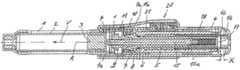
- FIG. 1depicts an injection apparatus of one exemplary embodiment of the present invention, in a perspective view
- FIG. 2shows, in a longitudinal section, the injection apparatus of FIG. 1 , including the coupler thereof, with the coupler open;
- FIG. 3shows the injection apparatus of FIG. 1 with the coupler closed
- FIG. 4is a detail from FIG. 2 ;
- FIG. 5is a detail from FIG. 3 ;
- FIG. 6shows the injection apparatus of FIG. 1 after a dosage has been set
- FIG. 7shows the injection apparatus of FIG. 1 after a reservoir has been emptied
- FIG. 8shows a decoupling member and a casing part of the injection apparatus of FIG. 1 ;
- FIG. 9shows a distal portion of the injection apparatus of FIG. 1 with the casing parts connected
- FIG. 10shows the distal portion while the casing parts are being detached
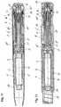
- FIG. 11shows, in a longitudinal section, another exemplary injection apparatus, with the coupler open
- FIG. 12shows the injection apparatus of FIG. 11 , with the coupler closed, in a different longitudinal section
- FIG. 13shows a detail from FIG. 11 ;
- FIG. 14shows a detail from FIG. 12 ;
- FIG. 15shows the injection apparatus of FIG. 11 , after a dosage has been set
- FIG. 16shows the injection apparatus of FIG. 11 , after the reservoir has been emptied
- FIG. 17shows the injection apparatus of FIG. 11 , with the casing parts detached from each other;
- FIG. 18shows a detail from FIG. 17 ;
- FIG. 19an injection device of another exemplary embodiment of the present invention.
- FIG. 20a proximal part of the injection device of FIG. 19 , with the coupler open;
- FIG. 21the injection device of FIG. 19 , with the coupler closed;
- FIG. 22the proximal part of the injection device of FIG. 19 , when correcting the dosage
- FIG. 23the proximal part of the injection device of FIG. 19 , after the reservoir has been emptied.
- FIG. 24a blocking member and a stopping member of the injection device of FIG. 19 .
- fastening, mounting, attaching or connecting components of the present inventionunless specifically described as otherwise, conventional mechanical fasteners and methods may be used.
- Other appropriate fastening or attachment methodsinclude adhesives, welding and soldering, the latter particularly with regard to the electrical system of the device, if any.
- suitable electrical components and circuitry, wires, wireless components, chips, boards, microprocessors, inputs, outputs, displays, control components, etc.may be used.
- the materials for making the present invention and/or its componentsmay be selected from appropriate materials such as metal, metallic alloys, ceramics, plastics, etc.
- FIG. 1shows one embodiment of the present invention comprising an injection apparatus comprising a first casing part 1 and a second casing part 4 detachably connected to each other.
- the casing parts 1 and 4are screwed to each other.
- the injection apparatusis formed as a slim injection pen.
- the casing part 1serves to accommodate a container 2 filled with a fluid product and in this sense forms a reservoir
- the casing part 4serves as a bearer for a dosing and drive means, a dosing member 18 of which can be seen.
- the casing part 4is breached in the region of the dosing member 18 , such that a user has direct access to the dosing member 18 .
- the dosing member 18is mounted such that it can be rotated about a central longitudinal axis of the apparatus, and formed as a sleeve which is ribbed on its outer circumference so as to be user-friendly.
- a dosage display 20can also be seen, which is laterally placed through a breach in the shell of the casing part 4 .
- FIG. 2shows the injection apparatus of the first exemplary embodiment, in a longitudinal section.
- the container 2is accommodated in the casing part 1 .
- a piston 3is accommodated such that it can be moved in an advancing direction V.
- the piston 3seals the container 2 , fluid-proof, at its proximal end.
- Advancing the piston 3 in the advancing direction Vdisplaces and delivers product through an outlet of the container 2 , e.g., through an injection needle protruding into the outlet and fastened to the distal end of the casing part 1 by a needle holder.
- the container 2may be formed in the manner of conventional ampoules.
- the casing part 1directly forms a container or ampoule holder.
- the proximal end of the casing part 1protrudes into the casing part 4 and is screwed to the casing part 4 .
- the casing part 4accommodates a piston rod 15 and other components comprising a dosing and drive means or mechanism.
- the dosing and drive meansincludes a drive member 5 and a coupler which in a coupled state, i.e. in a coupler engagement, couples the drive member 5 to the piston rod 15 .
- the piston rod 15together with the piston 3 , comprises a conveying means.
- coupler members 6 - 10transfer a drive force exerted on the drive member 5 onto the piston rod 15 .
- No coupler engagementexists in FIG. 2 , such that the piston rod 15 is decoupled from the drive member 5 .
- the usercan set the product dosage to be administered, by a dosing movement of the dosing member 18 , e.g., a rotational movement.
- the drive member 5is sleeve-shaped. On its shell outer area, it comprises a thread about a threaded axis R pointing in the advancing direction V. Via this thread, the drive member 5 is in threaded engagement with a coupler input member 6 .
- the coupler input member 6is also sleeve-shaped and provided with a corresponding inner thread for the threaded engagement. The thread pitch in the threaded engagement is large enough that self-locking cannot occur.
- the dosing member 18surrounds the coupler input member 6 and is connected to the coupler input member 6 such that it is secured against rotating and cannot be moved axially.
- the piston rod 15protrudes into the drive member 5 and the coupler input member 6 .
- the piston rod 15is provided with an outer thread over its axial length. Via the outer thread, it is in threaded engagement with a coupler output member 9 which is provided with a corresponding inner thread. These two threads also exhibit a thread pitch which prevents self-locking in the threaded engagement. The thread pitch is less than the thread pitch in the threaded engagement between the drive member 5 and the coupler input member 6 .
- a coupler sleeve 8is connected to the coupler output member 9 such that it is secured against rotating and cannot be moved axially.
- the coupler sleeve 8 and the coupler output member 9can be regarded as an integral component with respect to the movements between the drive member 5 and the piston rod 15 . They may be embodied in two parts and fixedly connected to each other.
- the coupler output member 9 and the coupler sleeve 8are mounted in the casing part 4 such that they can be rotated about the threaded axis R of the coupler output member 9 but cannot be moved axially.
- the piston rod 15protrudes through the coupler output member 9 and protrudes into the coupler sleeve 8 .
- the equalizing spring 17is clamped between a proximal end of the coupler sleeve 8 and a proximal end of the piston rod 15 and acts on the piston rod 15 in the advancing direction V as a pressure spring.
- the equalizing spring 17presses onto the piston rod 15 via a disc 15 a which is supported such that it can be rotated on the piston rod 15 and forms a flange of a sleeve placed onto the piston rod 15 .
- the piston rod 15is linearly guided in and counter to the advancing direction V in a linear guide 4 a , such that it cannot be rotated relative to the casing part 1 .
- the drive member 5is also linearly guided relative to the casing part 4 such that it can be moved in and counter to the advancing direction V, for which purpose the casing part 4 directly forms a linear guide 4 b.
- the threaded axis of the piston rod 15forms a main movement axis of the device. It forms a rotational axis R for the rotational drive movement of the coupler input member 6 and, via the coupler intermediate member 7 , the coupler output member 9 . It forms both threaded axes. It also forms the translational axis for the piston rod 15 and the drive member 5 .
- the coupleralso includes a coupler intermediate member 7 and a restoring member 10 which is formed as a pressure spring and charges the coupler intermediate member 7 with an elasticity force acting counter to the advancing direction V.
- the restoring member 10is clamped between the coupler output member 9 and the coupler intermediate member 7 .
- the restoring member 10ensures, via the coupler intermediate member 7 , that the coupler engagement is released. This state is shown in FIG. 2 .
- the coupler input member 6is pressed in the advancing direction V until it abuts against the coupler intermediate member 7 , and is pressed into a proximal end position by the restoring member 10 via the coupler intermediate member 7 .
- the restoring member 10holds the coupler input member 6 in a holding position relative to the coupler output member 9 and the coupler sleeve 8 fastened to it.
- the restoring member 10 and the coupler intermediate member 7thus form a holding means, acting in a non-positive lock, for the coupler input member 6 .
- FIG. 3shows the injection apparatus in a coupled state.
- a coupler engagementexists between the coupler input member 6 and the coupler sleeve 8 .
- the coupler input member 6 and the coupler sleeve 8form engaging elements which, in the coupler engagement, establish a rotationally secured connection between the two members 6 and 8 about the threaded axis R pointing in the advancing direction V.
- the engaging elementsco-operate as grooves and springs or teeth which are formed parallel to the advancing direction V and evenly distributed about the threaded axis R.
- FIGS. 4 and 5show the region of the coupler engagement in detail.
- FIG. 4shows the apparatus in the decoupled state
- FIG. 5shows the apparatus in the coupled state.
- FIG. 4thus corresponds to FIG. 2
- FIG. 5thus corresponds to FIG. 3 .
- the coupler input member 6is retracted from the coupler sleeve 8 counter to the advancing direction V, such that the coupler input member 6 can be freely rotated relative to the coupler sleeve 8 and therefore the coupler output member 9 fixedly connected to it.
- the coupler output member 9is simultaneously connected, such that it cannot be rotated, to the casing part 4 via the coupler sleeve 8 , the coupler intermediate member 7 and a decoupling member 11 .
- the coupler intermediate member 7is provided with engaging elements 7 b on an inner area radially facing the coupler sleeve 8
- the coupler sleeve 8is provided with corresponding engaging elements 8 b .
- the coupler intermediate member 7is provided with engaging elements 7 a on an outer circumferential area, and the decoupling member 11 is provided with radially facing engaging elements 11 a on a shell inner area which, in the decoupled state, interlock with each other—like the engaging elements 7 b and 8 b —in the manner of grooves and springs or teeth parallel to the advancing direction V.
- the coupler intermediate member 7in its rotationally secured engagement with the coupler sleeve 8 and its rotationally secured engagement with the decoupling member 11 , can be moved axially in and counter to the advancing direction V, wherein the engagement with the decoupling member 11 is released when it moves in the advancing direction V.
- the drive member 5If the drive member 5 is operated by exerting a pressure force on a triggering element 16 in the advancing direction V, the drive member 5 and the coupler input member 6 together complete an axial coupler stroke of length X.
- the coupler input member 6pushes the coupler intermediate member 7 in the advancing direction V, against the restoring elasticity force of the restoring member 10 .
- the engaging elements 6 a and 8 apass into engagement with each other, while the coupler intermediate member 7 simultaneously moves relative to the decoupling member 11 until it passes out of the rotationally secured engagement with the decoupling member 11 .
- the coupler intermediate member 7remains in the rotationally secured engagement with the coupler sleeve 8 .
- the coupler movementis limited by a stopper of the triggering element 16 on the coupler sleeve 8 ; in the exemplary embodiment, on its proximal facing area ( FIG. 3 ).
- FIG. 5shows the injection apparatus in the coupled state.
- the engaging elements 6 a and 8 aare axially superimposed, such that the coupler engagement is established as a rotationally secured engagement between the coupler input member 6 and the coupler sleeve 8 .
- the engagement between the coupler intermediate member 7 and the decoupling member 11is not released until the coupler engagement is securely established.
- a userrotates the dosing member 18 , which locks in easily releasable locking positions.
- the dosing member 18is connected to the coupler input member 6 such that it is secured against rotating and also cannot be moved axially, such that the latter rotates with it.
- the drive member 5 guided linearly in and counter to the advancing direction V at 4 bis moved, by the dosing movement of the coupler input member 6 , in the proximal direction and then protrudes out of the casing part 4 .
- the axial dosing path of the drive member 5follows from the rotational angle by which the dosing member 18 is rotated and the thread pitch in the threaded engagement between the drive member 5 and the coupler input member 6 which abuts against the coupler intermediate member 7 in the advancing direction V and against the casing part 4 counter to the advancing direction V.
- FIG. 6shows the injection apparatus with the container 2 still completely filled, after a first dosage has been set or selected.
- the userpenetrates the skin with the injection needle, for a subcutaneous injection.
- the useroperates the drive member 5 by pressing it in the advancing direction V, into the casing part 4 .
- the drive member 5slaves the coupler input member 6 , against the elastic restoring force of the restoring member 10 , until the coupler engagement with the coupler sleeve 8 is established and the rotationally secured engagement between the coupler intermediate member 7 and the decoupling member 11 is released.
- the coupler stroke Xis complete and a delivery stroke follows as the second portion of the drive movement.
- the drive member 5is pressed further in the advancing direction V. Since the coupler input member 6 cannot perform any further movement in the advancing direction V once it abuts axially against the coupler intermediate member 7 , it rotates—in the threaded engagement with the drive member 5 which is guided such that it is secured against rotating—about the common threaded axis R.
- the coupler input member 6slaves the coupler sleeve 8 , which slaves the coupler output member 9 .
- the coupler sleeve 8is held in the casing part 4 , together with the coupler output member 9 , such that it cannot be moved axially.
- the rotational movement of the coupler output member 9advances the piston rod 15 , via the threaded engagement with the piston rod 15 and its rotationally secured linear guide at 4 a , and thus causes the delivery movement of the piston rod 15 and together with it the piston 3 .
- the injection button 16passes into abutting contact against the coupler sleeve 8 in the course of the drive and delivery movement ( FIG. 3 ), the delivery process is complete.
- the restoring member 10moves the coupler input member 6 , via the coupler intermediate member 7 , back to the holding position retracted out of the coupler engagement, as shown in FIGS. 2 and 4 .
- the coupler input member 6 and together with it the drive member 5 , the dosing member 18 and the dosage display 20are decoupled from the coupler output member 9 and thus from the piston rod 15 by the retracting movement of the coupler input member 6 .
- the piston rod 15is again connected to the casing part 4 , such that it is secured against rotating, via the returning coupler intermediate member 7 and decoupling member 11 .
- FIG. 7shows the injection apparatus at the end of a final delivery which has emptied the container 2 .
- the casing part 1For exchanging the emptied container 2 , the casing part 1 is detached from the casing part 4 , e.g., by a unscrewing movement.
- the decoupling member 11is automatically moved relative to the casing part 4 , counter to the direction of the coupler movement of the coupler input member 6 and counter to the advancing direction V.
- the casing part 4mounts or carries the decoupling member 11 accordingly.
- the axial path which the decoupling member 11 thus travels relative to the casing part 4is as long as the coupler stroke X, such that once the casing parts 1 and 4 have been detached, the decoupling member 11 lying axially opposite the coupler input member 6 blocks it, and the coupler input member 6 can no longer be moved in the advancing direction V, at least not into the coupler engagement with the coupler sleeve 8 .
- Blocking the coupler input member 6 in the disengaged positionprevents the coupler output member 9 from being able to pass into a rotationally secured connection with the casing part 4 and so prevent the piston rod 15 from retracting. In other words, it ensures that the piston rod 15 can be retracted into the casing part 4 , without being blocked.
- FIG. 8shows the decoupling member 11 and the first casing part 1 in a perspective view.
- the decoupling member 11is a sleeve part and comprises, in a distal portion, three engaging elements 12 protruding radially inwardly and, in a proximal portion, a fixing element 13 protruding radially outwardly.
- FIG. 9shows the casing part 1 and a connecting portion of the casing part 4 , wherein the hidden decoupling member 11 is shown by a broken line.
- the decoupling member 11is accommodated in the connecting portion of the casing part 4 such that it can be rotated and moved axially.
- Its relative mobilityis determined by an axial guide 4 e and a circumferential guide 4 c , along which the fixing element 13 moves in succession when the casing part 1 is detached from the casing part 4 .
- the circumferential guide 4 cextends at a right angle to the axial guide 4 e , in the circumferential direction about the screw axis. It is formed as a breach or cavity in the casing part 4 .
- the decoupling member 11is in a guiding engagement with the casing part 1 .
- one guiding curve 1 a per engaging element 12is formed on a shell outer area of the casing part 1 and guides the engaging element 12 and, thus, the decoupling member 11 when the casing parts 1 and 4 are detached.
- Another guiding curve 1 aspaced in parallel, guides the decoupling member 11 accordingly, when the casing parts 1 and 4 are connected ( FIG. 10 ).
- the guiding curve 1 aruns obliquely, i.e.
- the pitchmeasures about 45° and is constant.
- itcan be selected from the entire range larger than 0° and smaller than 180° and, as applicable, can also be variable, as long as the relative movement required for detaching the casing parts 1 and 4 causes a movement of the decoupling member counter to the coupler movement X to be performed by the coupler input member for coupling.
- a distal portion of the guiding curve 1 aruns axially, such that when the casing parts 1 and 4 are screwed further apart, the fixing element 13 is moved along the circumferential guide 4 c .
- the fixing element 13slides over a fixing element 4 d in the region of the circumferential guide 4 c .
- the fixing element 4 dis formed as a cam on a strip portion of the casing part 4 .
- the strip portionacts as a spiral spring which is fixedly clamped on both sides and elastically gives when the fixing element 13 moves over the fixing element 4 d , to then spring back again into its initial position and form a releasable locking engagement for the decoupling member 11 .
- the fixing element 13In the locking position, the fixing element 13 abuts the fixing element 4 d in one circumferential direction and in the other circumferential direction abuts a collar formed in the circumferential guide 4 c and is thus fixed in both circumferential directions.
- FIG. 10shows the two casing parts 1 and 4 and the decoupling member 11 , after its fixing element 13 has been moved behind the fixing element 4 d of the casing part 4 .
- the decoupling member 11is in the releasable locking engagement with the casing part 4 via the fixing elements 4 d and 13 and in this way is axially fixed on the casing part 4 such that it is secured against rotating.
- the decoupling member 11blocks the coupler input member 6 and thus ensures that the drive member 5 and the piston rod 15 are decoupled.
- its engaging element 12moves out of the guiding engagement with the guiding curve 1 a when the casing parts 1 and 4 are screwed further apart.
- the guiding curve 1 ais shaped accordingly.
- the dosage display 20 of the first exemplary embodimentis coupled to the drive member 5 via a display coupling member 21 and the coupler input member 6 .
- the display coupling member 21is connected to the coupler input member 6 such that it is secured against rotating, by being able to move on the coupler member 6 relative to it in and counter to the direction of the coupler movement X, forming a ring in the exemplary embodiment.
- the display coupling member 21can be rotated with respect to the casing part 4 about the rotational axis R, but is held such that it cannot be moved axially relative to the casing part 4 .
- the display coupling member 21circumferentially comprises teeth, which in the exemplary embodiment are conical, via which it is in toothed engagement with a gear of the dosage display 20 to introduce the dosing movement and also the drive movement into the gear.
- FIGS. 11-18show an injection apparatus of another exemplary embodiment of the present invention.
- the injection apparatusexhibits some modifications with regard to the coupling and decoupling of the drive member 5 and piston rod 15 .
- the drive member 5 and the piston rod 15themselves, and how they co-operate in principle when coupling and decoupling, may remain the same.
- Functionally identical componentsare provided with the same reference numbers as in the first exemplary embodiment, and, to indicate modifications the relevant components are provided with the same reference numbers, but apostrophised.
- FIG. 11shows the injection apparatus in its resting state, in which the drive member 5 is decoupled from the piston rod 15 .
- the first casing part 1is covered by a protective cap 37 which is connected to the casing part 4 and removed for administering the product.
- the coupler engagementis established and released between the modified coupler input member 6 ′ and the modified coupler intermediate member 7 ′.
- FIG. 12shows the injection apparatus of the second embodiment in its coupled state, which is established by charging the triggering element 16 , and therefore the drive member 5 and the coupler input member 6 ′, with a drive force acting in the advancing direction V.
- the protective cap 37has been replaced by a casing part 38 which is placed onto the casing part 4 and snapped onto it.
- the casing part 38mounts or carries a needle protection 39 , e.g., in the form of a needle protecting sleeve, such that it can be elastically moved counter to the advancing direction V.
- the needle protection 39springs counter to the advancing direction V, into the casing part 38 . In a reversal of this movement, the needle penetrates through a distal opening of the needle protection 39 .
- FIGS. 13 and 14show the region of the coupler engagement in detail, wherein FIG. 13 shows for the decoupled state and FIG. 14 shows for the coupled state.
- the engaging elements 6 a and 7 c between which the coupler engagement is establishedexhibit an inclination with respect to the advancing direction V.
- the engaging elements 6 a and 7 care each formed in the manner of a conical toothed ring encircling the threaded axis of the piston rod 15 , wherein the coupler input member 6 ′ forms its engaging elements 6 a on its distal end as an inner cone, and the coupler intermediate member 7 ′ forms the engaging elements 7 c on its proximal end as an outer cone.
- the conical engaging areasare congruent to each other and lie directly opposite each other, axially facing, with the clear distance X.
- the coupler areascould also be otherwise suitably shaped, e.g., congruently convex/concave.
- the coupler intermediate member 7 ′can be moved axially and is in engagement with the coupler output member 9 , such that it is secured against rotating, in any axial position. It is again formed as a sleeve part and mounted on the coupler output member 9 such that it can be slid axially. For this purpose, it penetrates through the coupler sleeve 8 ′ which is axially slit accordingly, which however is not visible in the figures.
- the rotationally secured connectionis created in a positive lock via engaging elements formed as axially linear teeth.
- the restoring member 10 ′which is the same in its embodiment and installation but reduced with regard to its function, is tensed between the coupler output member 9 and the coupler intermediate member 7 ′, as in the first embodiment, and charges the latter with an elasticity force, counter to the advancing direction V.
- the restoring member 10 ′presses the coupler intermediate member 7 ′ into the rotationally secured engagement with the decoupling member 11 ′.
- the corresponding engaging elementsare again indicated as 7 a and 11 a .
- the engaging elements 7 a and 11 aare also formed as conical toothed rings.
- the engagement between the coupler intermediate member 7 ′ and the decoupling member 11 ′can alternatively be in a purely frictional lock.
- the engaging elements 7 a and 11 acomprise mutually facing congruent frictional areas which could be mutually facing conical areas.
- the dosing member 18 ′Another modification exists in the dosing member 18 ′. Unlike the dosing member 18 of the first embodiment, the dosing member 18 ′ cannot be moved relative to the casing part 4 in the direction of the coupler movement X. Instead, the coupler input member 6 ′ is again connected to the dosing member 18 ′ such that it is secured against rotating, but such that it can be moved axially. The rotationally secured engagement between the coupler input member 6 ′ and the dosing member 18 ′ exists in the decoupled state of the drive member 5 and the piston rod 15 and is released in the course of the coupler stroke X, namely directly before the rotationally secured connection between the coupler output member 9 and the casing part 4 is released.
- the coupler input member 6 ′ and the dosing member 18 ′are provided with engaging elements 6 b and 18 a which are formed on shell areas, radially facing each other, of the two members 6 ′ and 18 ′ in the manner of grooves and springs.
- FIGS. 11 and 12With respect to the rotationally secured connection between the coupler input member 6 ′ and the dosing member 18 ′, reference may also be made to FIGS. 11 and 12 .
- the rotationally secured connectionexists in the decoupled state shown in FIG. 11 , and is released in the coupled state shown in FIG. 12 .
- the restoring member 10 ′has no effect which separates the coupler members 6 ′ and 9 from each other.
- the holding means of the second embodimentincludes a restoring member 14 , a supporting structure 6 c and the dosing member 18 ′.
- the restoring member 14charges the coupler input member 6 ′, via the supporting structure 6 c , with an elastic restoring force which counteracts the coupler movement X of the coupler input member 6 ′.
- the restoring member 14is supported on the dosing member 18 ′ which forms a supporting collar for this purpose.
- the supporting structure 6 cis connected to the coupler input member 6 ′ such that it cannot be moved in or counter to the direction of the coupler movement X. It is formed as a short sleeve with an outer flange on which the restoring member 14 is supported. Counter to the direction of the coupler movement X, the supporting structure 6 c abuts with respect to the casing part 4 .
- the coupler movement Xmoves the coupler input member 6 ′, against the elastic restoring force of the restoring member 14 , into the coupler engagement with the coupler intermediate member 7 ′.
- the restoring member 14is formed as a pressure spring charged with a pressure force in the direction of the coupler movement X.
- the mode of operation of the modified coupler(comprising components 6 ′- 11 ′ and 14 ′) is the same as the coupler of the first embodiment.
- the coupler output member 9is connected, such that it is secured against rotating, to the casing part 4 via the coupler sleeve 8 ′, the coupler intermediate member 7 ′ and the decoupling member 11 ′.
- Operating the injection button 16 and consequently performing the coupler stroke Xestablishes the coupler engagement, in the second embodiment between the coupler input member 6 ′ and the coupler intermediate member 7 ′.
- the engaging elements 6 a and 7 cinterlock with each other, such that the coupler input member 6 ′ is connected, such that it is secured against rotating, to the coupler output member 9 via the coupler intermediate member 7 ′ and the coupler sleeve 8 ′. Only once the rotationally secured engagement has been established is the coupler intermediate member 7 ′ moved out of engagement with the decoupling member 11 ′ by the coupler input member 6 ′ pressing in the advancing direction V, such that the coupler output member 9 can freely rotate about the threaded axis R formed with the piston rod 15 and the coupler engagement is completely established.
- FIG. 14shows the injection apparatus in its coupled state, i.e. in the coupler engagement.
- FIGS. 15 and 16correspond to FIGS. 6 and 7 of the first exemplary embodiment, such that cross-reference can be made.
- FIG. 17shows the injection apparatus of the second embodiment while the reservoir 2 is being exchanged.
- the casing part 1is already accommodating the new reservoir 2 .
- the casing part 1can be moved towards the casing part 4 using the piston 3 which proximally seals the reservoir 2 .
- the piston rod 15 which freely protrudes out of the casing part 4is moved back by the pressing piston 3 in the threaded engagement with the coupler output member 9 which can be freely rotated but is axially fixed.
- the piston rod 15Due to the rotationally secured linear guide 4 a , which in the second embodiment is formed by a coupler receptacle which is inserted into the casing part 4 such that it is secured against rotating, the piston rod 15 completes an axial linear movement when retracted, while the coupler output member 9 freely rotates, together with the coupler sleeve 8 ′, about the common threaded axis. Instead of moving the piston rod 15 back, pressing against the piston 3 , the piston rod 15 can also be moved back beforehand by pressing directly on its plunger.
- FIG. 18shows the coupler region, with the decoupling member 11 ′ situated in the decoupling position, in detail.
- the function of the decoupling member 11 ′corresponds to that of the first embodiment, namely blocking the coupler input member 6 ′ in the retracted axial position.
- the dosing movement and the drive movementare also introduced into a gear of the dosage display 20 ′ via the coupler input member 6 ′ and a display coupling member 22 in the second embodiment.
- the display coupling member 22is also connected to the coupler input member 6 ′, such that it is secured against rotating, and cannot be moved relative to the casing part 4 in and counter to the direction of the coupler movement X.
- FIGS. 19-24show another exemplary embodiment of an injection apparatus in accordance with the present invention in which, during administering, the drive force for delivering the product is not applied manually but rather by a drive member 25 formed as a drive spring.
- the drive member 25is tensed by setting the dosage to be administered.
- the spring energy absorbed when setting the dosageis released when the apparatus is triggered and converted into advancing the piston rod 15 .
- FIG. 19shows the injection apparatus with the assembled casing part 38 and the needle protection 39 accommodated in it such that it can be slid counter to the advancing direction V, against the force of a restoring spring.
- FIGS. 20 and 21show the casing part 4 with the operational and other components of the injection apparatus accommodated in it.
- FIG. 20it is in a resting state, comparable to the preceding embodiments, in which the dosage can be set and, in FIG. 21 , it is in the coupler engagement.
- FIGS. 20 and 21show the casing part 4 with the operational and other components of the injection apparatus accommodated in it.
- FIG. 20it is in a resting state, comparable to the preceding embodiments, in which the dosage can be set and, in FIG. 21 , it is in the coupler engagement.
- FIGS. 20 and 21show the casing part 4 with the operational and other components of the injection apparatus accommodated in it.
- FIG. 20it is in a resting state, comparable to the preceding embodiments, in which the dosage can be set and, in FIG. 21 , it is in the coupler engagement.
- FIGS. 20 and 21show the casing part 4 with the operational and other components of the injection apparatus accommodated in it.
- FIG. 20
- the drive member 25is a spiral spring acting as a torsion spring, comprising spring windings which encircle the threaded axis R of the threaded engagement between the coupler output member 9 and the piston rod 15 .
- the spring windingsare arranged one over the other, radially with respect to the threaded axis R; they exhibit a zero pitch with respect to the threaded axis.
- An inner end of the spring windingsis fastened to the coupler input member 6 ′, and an outer end is fastened to a supporting structure 26 which is connected to the casing part 4 such that it can be moved in the direction of the coupler movement X but is secured against rotating.
- the supporting structure 26is connected to the coupler input member 6 ′ such that it cannot be moved in and counter to the direction of the coupler movement X.
- the coupler input member 6 ′can be rotated about the threaded axis R relative to the supporting structure 26 .
- Another supporting structure 6 dis connected to the coupler input member 6 ′ such that it cannot be moved in and counter to the direction of the coupler movement X.
- the coupler input member 6 ′ and the supporting structure 6 dmay be formed integrally.
- the drive member 25is axially enclosed by the supporting structures 6 d and 26 .
- the functionality of the couplercorresponds generally to that of the second embodiment, such that the same reference signs are used for the coupler members 6 ′- 10 ′ and the decoupling member 11 ′. Unlike the coupler of the second embodiment, however, the coupler sleeve 8 ′ in that embodiment has been omitted.
- the coupler intermediate member 7 ′is directly in an engagement with the coupler output member 9 which transfers the rotational drive movement of the coupler input member 6 ′ onto the coupler output member 9 .
- a dosage display 20 ′′is coupled to the coupler input member 6 ′ via a display coupling member 23 .
- the display 20 ′′is connected to the coupler input member 6 ′, such that it is secured against rotating.
- the display coupling member 23cannot be moved in and counter to the direction of the coupler movement X relative to the casing part 4 .
- the rotationally secured connection of the display coupling member 23exists both in the decoupled and in the coupled state of the device.
- a rotational block or lockis formed between the coupler casing 6 ′ and the casing part 4 .
- the rotational blockexists between a first blocking member 24 and a second blocking member 34 .
- the blocking member 24is connected to the coupler input member 6 ′, such that it is secured against rotating.
- the blocking member 34is connected to the casing part 4 , such that it is secured against rotating but can be moved in and counter to the direction of the coupler movement X relative to the casing part 4 and the coupler input member 6 ′.
- the facing areas of the blocking members 24 and 34which contact each other in the blocking engagement, form a ratchet which allows a rotational movement of the coupler input member 6 ′ which tenses the drive member 25 , and prevents a rotational movement in the opposite direction.
- FIG. 24shows the coupler input member 6 ′ together with the blocking member 24 mounted on it, such that it is secured against rotating, the display coupling member 23 connected to the coupler input member 6 ′, such that it is secured against rotating, and a connecting part 33 connected to the input member 6 ′ such that it cannot be moved.
- the display coupling member 23forms a units counting ring of the dosage display 20 ′′ and is suitably coupled to a tens counting ring to display the dosage set.
- the blocking member 24is provided with blocking teeth 24 a which are arranged evenly about the axis R and, in the blocking engagement, co-operate with counter teeth of the blocking member 34 , to form the rotational block with respect to the drive movement.
- a shell outer area of the blocking member 24is provided with a thread 24 b , the threaded axis of which coincides with the threaded axis R of the piston rod 15 .
- a stopping member 27engages with the thread 24 b .
- the stopping member 27is guided such that it can be linearly moved parallel to the threaded axis R, in the exemplary embodiment, in an axial groove on the inner shell area of the casing part 4 .
- the blocking member 24forms a rotational stopper 24 c for the stopping member 27 , which limits the drive movement of the coupler input member 6 ′ which advances the piston rod 15 .
- Another stopping member 27is arranged on the other side of the threaded axis R, opposite the stopping member 27 which can be seen in the view in FIG. 23 , and co-operates in the same way with two other rotational stoppers 24 c and 24 d .
- the thread 24 dis double-threaded.
- the stopping members 27simultaneously abut against the respectively assigned rotational stoppers 24 c and 24 d , as can be seen in the cross-sectional representation in FIG. 23 for the rotational stoppers 24 c .
- the rotational stoppers 24 cdetermine a zero dosage position and the rotational stoppers 24 d determine a maximum dosage position.
- the holding meansis formed in another variant. It includes a restoring member 19 , as well as the display coupling member 23 and the blocking member 24 .
- the restoring member 19is supported on the casing part 4 via the display coupling member 23 in the direction of the coupler movement X and on the blocking member 24 counter to the direction of the coupler movement X.
- the restoring member 19presses the blocking member 24 until it abuts against the connecting part 33 .
- the connecting part 33Since the connecting part 33 is connected to the coupler input member 6 ′ such that it cannot be moved in and counter to the direction of the coupler movement X, the restoring member 19 thus exerts an elastic restoring force, acting counter to the direction of the coupler movement X, on the coupler input member 6 ′ via the blocking member 24 and the connecting part 33 , said elastic restoring force holding the coupler input member 6 ′ in the holding position retracted out of the coupler engagement. It again acts as a pressure spring.
- the blocking member 24is a sleeve part comprising an outer shell forming the thread 24 b , an inner shell serving to mount it on the coupler input member 6 ′ such that it is secured against rotating, and a base which connects the two shells and on which the blocking teeth 24 a are formed.
- the restoring member 19protrudes into the blocking member 24 which is cup-shaped in this way, and is supported on the base of the blocking member 24 .
- the restoring member 19presses the blocking member 24 not only until it abuts against the connecting part 33 , but also until it abuts against the casing part 4 . Abutting in this other way prevents the blocking member 24 from being able to move counter to the direction of the coupler movement X beyond the holding position assumed in FIG. 20 .
- the blocking member 24can thus be moved relative to the coupler input member 6 ′, against the restoring elasticity force of the restoring member 19 , in the direction of the coupler movement X.
- the coupler input member 6 ′can be moved counter to the direction of the coupler movement X relative to the blocking member 24 abutting against the casing part 4 .
- the equalizing spring 17tensed between the piston rod 15 and the connecting part 33 , supports the restoring member 19 in its function of holding the coupler input member 6 ′ in the holding position.
- the equalizing spring 17could in principle replace the restoring member 19 for retracting the coupler members 6 ′, 7 ′ and 9 . It is weak enough that, at least once it has been partially relaxed, it can no longer hold the coupler members 6 ′- 9 in the holding position, and thus can no longer hold the coupler in the decoupled state, with certainty.
- a triggering element 28is provided for triggering the drive member 25 .
- the triggering element 28can be moved translationally relative to the casing part 4 in the direction of the coupler movement X—in this embodiment, the advancing direction V and/or distal direction—and rotationally about the rotational axis R of the coupler input member 6 ′, which coincides with the threaded axis R of the piston rod 15 , and is guided in these two movements by the casing part 4 .
- the translational movement in the distal directionestablishes the coupler engagement between the coupler input member 6 ′ and the coupler intermediate member 7 ′ and releases the rotational block between the blocking members 24 and 34 , which triggers the drive member 25 , i.e. delivery.
- the translational movement in the advancing direction Vis therefore also referred to in the following as the triggering movement.
- the triggering element 28forms the dosing member of the third embodiment.
- the rotational movement of the triggering element 28 relative to the casing part 4sets the product dosage which can be delivered by the next delivery process. This movement is also referred to in the following as the dosing movement. From the zero dosage position, which is shown in FIG. 20 and determined by the stopping members 27 abutting the rotational stoppers 29 c of the blocking member 24 which limit the drive movement of the coupler input member 6 ′, the dosage can be set by rotating the triggering element 28 in the direction of the rotational direction arrow indicated, the dosing direction.
- the rotational dosing movement of the triggering element 28is transferred onto the coupler input member 6 ′ via an inner part 29 —which is connected to the triggering element 28 such that it is secured against rotating and shifting or is formed integrally with it—and the connecting part 33 .
- the inner part 29 and the connecting part 33are in an engagement with each other, such that they are secured against rotating, and the connecting part 33 is connected to the coupler input member 6 ′, such that it is secured against rotating.
- the inner part 29 and the connecting part 33are provided with an inner teeth 29 a and an outer teeth 33 a which interlock with each other in the resting state of the apparatus and can be axially shifted with respect to each other.
- the triggering element 28is arranged in the proximal end region of the casing part 4 so as to be user-friendly. Its outer sleeve part surrounds the casing part 4 . A base of the triggering element 28 forms a proximal end of the injection apparatus.
- the triggering element 28can be operated as a turning button and is ribbed on its outer shell area for this purpose. For triggering, it can be operated as a push button.
- the triggering element 28locks with the casing part 4 in discrete rotational angular positions corresponding to the dosage units.
- a stopper element 29 b facing a proximal facing area of the connecting part 33projects radially inwards from the inner part 29 .
- a clear distanceremains between the connecting part 33 and the stopper element 29 b , said clear distance being just large enough that the rotational block between the inner part 29 and the connecting part 33 is released during the triggering movement of the triggering element 28 , before the stopper element 29 b terminates the relative movement of the triggering element 28 relative to the connecting part 33 by an abutting contact.
- the second blocking member 34is tensed in the blocking engagement with the blocking member 24 by a blocking spring 31 .
- the blocking spring 31is supported in the direction of the coupler movement X on the blocking member 34 and counter to the coupler movement X on a casing part 30 which is fixedly connected to the casing part 4 .
- Another spring 32arranged between the inner part 29 and the blocking member 34 , tenses the triggering element 28 relative to the blocking member 34 into a proximal end position.
- the blocking member 34is axially guided, such that it is secured against rotating, by the casing part 4 .
- the casing part 4forms a distal and a proximal stopper for the mobility of the blocking member 34 .
- the usersets the dosage by rotating the triggering element 28 in the dosing direction.
- the triggering element 28slaves the connecting part 33 via the rotational block 29 a , 33 a , and the connecting part 33 for its part slaves the coupler input member 6 ′ which thus completes the same rotational dosing movement as the triggering element 28 .
- Rotating the coupler input member 6 ′tenses the drive member 25 .
- the stopping member 27migrates from the stopper 24 c of the thread 24 b which determines the zero dosage, in the direction of the stopper 24 d which determines the maximum dosage ( FIG. 24 ).
- the injection apparatusalso offers a convenient way of correcting the dosage, as is clear from a comparison of FIGS. 20 and 22 . If the user has inadvertently set too high a dosage, he/she can correct the dosage by rotating the coupler input member 6 ′ back. For correcting the dosage, the user pulls the triggering element 28 in the proximal direction. This retracting movement of the triggering element 28 is indicated in FIG. 22 by an arrow, as is the rotational direction for correcting. In the resting state of the apparatus, the inner part 29 and the blocking member 34 are in a slaving engagement with respect to a movement in the proximal direction. The corresponding slaving elements are indicated as 29 c and 34 a .
- the slaving element 29 c formed by the inner part 29 and the slaving element 34 a formed by the blocking member 34grip behind each other and form a latch for the retracting movement of the triggering element 28 .
- Pulling on the triggering element 28thus also moves the blocking member 34 in the proximal direction, against the force of the blocking spring 31 , thus releasing it from the blocking engagement with the blocking member 24 which abuts against the casing part 4 .
- the usercan correct the dosage by means of a reverse rotational movement of the triggering element 28 and the still extant rotationally secured engagement between the inner part 29 and the connecting part 33 .
- the userreleases the triggering element 28 , it snaps back in the distal direction together with the blocking member 34 due to the effect of the blocking spring 31 , and the blocking member 34 thus snaps back into the blocking engagement with the blocking member 24 .
- the userexpediently continues to hold the triggering element 28 fast, which is facilitated by the rotational angular locking positions of the triggering element 28 . In principle, however, the user can also let it snap back and re-dose, as applicable.
- the apparatusis placed onto the skin at the desired administering location, and the injection needle is injected.
- the triggering element 28takes on another function, for which purpose it is coupled to the needle protection 39 ( FIG. 19 ).
- a first phase of injectingthe user presses the injection apparatus against the skin, such that the needle protection 39 is moved in the distal direction relative to the casing part 38 .
- this first part of the movement of the needle protection 39does not yet expose the injection needle; rather, its tip remains short of the needle protection 39 .
- the needle protection 39abuts against a resisting element, such that it cannot be moved further in the distal direction relative to the casing part 38 .
- the userpresses the triggering element 28 in the proximal direction.
- the triggering element 28releases an abutting contact between the needle protection 39 and the resisting element, such that the injection apparatus, and together with it the injection needle, are moved relative to the needle protection 39 in the direction of the skin, and the injection needle injects.
- the triggering element 28 for injecting the needlereference may be made to the patent application entitled “Attachment Module for an Injection Device Comprising an Engagement Control for a Needle Covering Element” owned by the owner of the present application.
- the drive member 25can be released and the product delivered by pressing further onto the triggering element 28 .
- the triggering element 28 and therefore the inner part 29is pressed further in the distal direction relative to the connecting part 33 , against the pressure of the spring 32 , such that the rotational block (formed by components 29 a , 33 a ) is released.
- the triggering element 28can rotate idly.
- the stopper element 29 bpasses into abutting contact with the connecting part 33 .
- the triggering element 28presses the connecting part 33 and therefore the coupler input member 6 ′ via the stopper element 29 b , in the direction of the coupler movement X; in exemplary embodiments, in the advancing direction V. Due to the effect of the spring force of the blocking spring 31 , the blocking member 34 follows this movement until it abuts against the casing part 4 . Before the blocking member 34 reaches the abutting position, the coupler input member 6 ′ passes into the coupler engagement with the coupler intermediate member 7 ′. The coupler input member 6 ′ presses the coupler intermediate member 7 ′ out of the frictional-lock blocking engagement with the decoupling member 11 ′, against the force of the restoring member 10 ′.
- the blocking member 34abuts the casing part 4 .
- the triggering element 28presses the blocking member 24 out of the blocking engagement with the blocking member 34 via the connecting part 33 .
- the rotational drive movement of the coupler input member 6 ′is initiated due to the drive force of the drive member 25 and is transferred onto the coupler output member 9 via the coupler engagement. Because it is guided,—such that it is secured against rotating—in the linear guide 4 a , the piston rod 15 is moved—in the threaded engagement with the coupler output member 9 —in the advancing direction V, and product is delivered. This delivery movement is terminated by the stopping member 27 abutting the stopper 24 c of the blocking member 24 which determines the zero dosage.
- FIG. 21shows the injection apparatus when a zero dosage or a small priming dosage is set, in the coupled state after the rotational block has been released, i.e. after the triggering element 28 has completely performed the triggering movement. If, advantageously, pressure is continuously exerted on the triggering element 28 , the triggering sequence described above progresses automatically, from injecting to completely delivering the dosage set.
- FIG. 23shows the injection apparatus after the container 2 has been emptied.
- the casing part 1has already been removed from the casing part 4 .
- the piston rod 15assumes its most distal position.
- the decoupling member 11 ′blocks the coupler input member 6 ′ in the position retracted from the coupler intermediate member 7 ′.
- the functionality of the decoupling member 11 ′corresponds to that in the other embodiments. Unlike the two first embodiments, however, the casing part 1 and the decoupling member 11 ′ are not directly in a guiding engagement with each other, but rather via an adaptor structure 36 .
- the adaptor structure 36is a sleeve in the casing part 4 which is fixed in and counter to the direction of the coupler movement X in the connecting portion, but can be rotated about the central longitudinal axis R of the casing part 4 .
- the adaptor structure 35forms a guiding curve 36 a either as a cavity on or a breach in its shell area facing the decoupling member 11 ′.
- the guiding curve 35 aexhibits the course of a threaded portion.
- the length measured over the circumference and the pitch of the guiding curve 35 a measured with respect to the central longitudinal axis of the casing part 4are dimensioned such that the decoupling member 11 ′ is moved into the decoupling position shown in FIG.
- the adaptor structure 35When connecting the casing parts 1 and 4 , the adaptor structure 35 forms a linear guide for the casing part 1 .
- the casing part 1is inserted into the adaptor structure 35 , wherein a slight frictional lock and correspondingly a sliding guide for the casing part 1 exists.
- the casing part 1cannot be rotated about the central longitudinal axis of the casing part 4 relative to the adaptor structure 35 .
- the engagementwhich is rotationally secured accordingly, is established right at the beginning of inserting the casing part 1 into the adaptor structure 35 .
- the casing part 1is rotated relative to the casing part 4 and slaves the adaptor structure 36 during this rotational movement, until the engaging element 12 of the decoupling member 11 ′ abuts the end of the guiding curve 36 a .
- the rotational movement of the casing part 1is, in some preferred embodiments, not possible until its axial abutting position, for which purpose a rotational block acting up until the abutting position can also be formed between the casing parts 1 and 4 .
- the movement of the decoupling member 11 ′ caused in the guiding engagementexhibits an axial length which is greater than the length X of the complete coupler movement.
- the decoupling member 11 ′presses the coupler input member 6 ′ beyond its holding position as assumed in the resting state, and blocks it in said decoupling position.
- the coupler input member 6 ′slaves the triggering element 28 via the stopper element 29 b .
- the blocking member 34is also slaved, against the force of the blocking spring 31 , and moved out of the blocking engagement.
- the blocking member 24cannot follow the blocking member 34 , since it is abutting against the casing part 4 .
- the coupler input member 6 ′has not yet assumed the zero dosage position, it is rotated now at the latest into the zero dosage position by the drive member 25 , and the dosage display 20 ′′ is zeroed.
- the dosage display 20 ′′is reset in accordance with the delivered dosage. If, one time, the dosage set was not delivered, for example because the injection process was aborted or the container 2 no longer contained the complete dosage set, the user can read this from the dosage display 20 ′′ which is then only partially reset.
Landscapes
- Health & Medical Sciences (AREA)
- Engineering & Computer Science (AREA)
- Hematology (AREA)
- Life Sciences & Earth Sciences (AREA)
- Vascular Medicine (AREA)
- Anesthesiology (AREA)
- Biomedical Technology (AREA)
- Heart & Thoracic Surgery (AREA)
- Veterinary Medicine (AREA)
- Public Health (AREA)
- Animal Behavior & Ethology (AREA)
- General Health & Medical Sciences (AREA)
- General Engineering & Computer Science (AREA)
- Mechanical Engineering (AREA)
- Environmental & Geological Engineering (AREA)
- Infusion, Injection, And Reservoir Apparatuses (AREA)
Abstract
Description
Claims (22)
Priority Applications (4)
| Application Number | Priority Date | Filing Date | Title |
|---|---|---|---|
| US16/127,951US11065393B2 (en) | 2004-12-31 | 2018-09-11 | Device for the dosed administration of a fluid product, adapted for the replacement of a container |
| US17/368,936US11931558B2 (en) | 2004-12-31 | 2021-07-07 | Device for the dosed administration of a fluid product, adapted for the replacement of a container |
| US18/441,221US20240252764A1 (en) | 2004-12-31 | 2024-02-14 | Device for the dosed administration of a fluid product, adapted for the replacement of a container |
| US18/734,913US20240316282A1 (en) | 2004-12-31 | 2024-06-05 | Device for the dosed administration of a fluid product |
Applications Claiming Priority (10)
| Application Number | Priority Date | Filing Date | Title |
|---|---|---|---|
| DE102004063645ADE102004063645A1 (en) | 2004-12-31 | 2004-12-31 | Device for metered administration of a fluid product with decoupling for a container change |
| DE102004063644ADE102004063644A1 (en) | 2004-12-31 | 2004-12-31 | Device for the dosed administration of a fluid product with torsion spring drive |
| DE102004063645.1 | 2004-12-31 | ||
| DE102004063648ADE102004063648A1 (en) | 2004-12-31 | 2004-12-31 | Injection or infusion device with life-determining device |
| DE102004063647ADE102004063647A1 (en) | 2004-12-31 | 2004-12-31 | Device for metered administration of a fluid product with coupling |
| PCT/CH2005/000710WO2006069454A1 (en) | 2004-12-31 | 2005-11-30 | Device for the dosed administration of a fluid product, provided with decoupling means for the replacement of a container |
| US11/769,496US7976494B2 (en) | 2004-12-31 | 2007-06-27 | Device for the dosed administration of a fluid product, adapted for the replacement of a container |
| US13/178,893US9057369B2 (en) | 2004-12-31 | 2011-07-08 | Device for the dosed administration of a fluid product, adapted for the replacement of a container |
| US14/735,991US10099017B2 (en) | 2004-12-31 | 2015-06-10 | Device for the dosed administration of a fluid product, adapted for the replacement of a container |
| US16/127,951US11065393B2 (en) | 2004-12-31 | 2018-09-11 | Device for the dosed administration of a fluid product, adapted for the replacement of a container |
Related Parent Applications (1)
| Application Number | Title | Priority Date | Filing Date |
|---|---|---|---|
| US14/735,991ContinuationUS10099017B2 (en) | 2004-12-31 | 2015-06-10 | Device for the dosed administration of a fluid product, adapted for the replacement of a container |
Related Child Applications (1)
| Application Number | Title | Priority Date | Filing Date |
|---|---|---|---|
| US17/368,936ContinuationUS11931558B2 (en) | 2004-12-31 | 2021-07-07 | Device for the dosed administration of a fluid product, adapted for the replacement of a container |
Publications (2)
| Publication Number | Publication Date |
|---|---|
| US20190001071A1 US20190001071A1 (en) | 2019-01-03 |
| US11065393B2true US11065393B2 (en) | 2021-07-20 |
Family
ID=40491053
Family Applications (7)
| Application Number | Title | Priority Date | Filing Date |
|---|---|---|---|
| US11/316,208AbandonedUS20060153693A1 (en) | 2004-12-31 | 2005-12-22 | Administering apparatus comprising a service life timer |
| US11/769,194Active2029-01-14US8409148B2 (en) | 2004-12-31 | 2007-06-27 | Device for the dosed administration of a fluid product, provided with a coupling |
| US11/769,496Expired - Fee RelatedUS7976494B2 (en) | 2004-12-31 | 2007-06-27 | Device for the dosed administration of a fluid product, adapted for the replacement of a container |
| US11/769,213Active2028-01-18US7951113B2 (en) | 2004-12-31 | 2007-06-27 | Device for the dosed administration of a fluid product comprising a torsion spring drive |
| US13/178,893Active2027-11-14US9057369B2 (en) | 2004-12-31 | 2011-07-08 | Device for the dosed administration of a fluid product, adapted for the replacement of a container |
| US14/735,991Active2026-09-23US10099017B2 (en) | 2004-12-31 | 2015-06-10 | Device for the dosed administration of a fluid product, adapted for the replacement of a container |
| US16/127,951Active2026-07-02US11065393B2 (en) | 2004-12-31 | 2018-09-11 | Device for the dosed administration of a fluid product, adapted for the replacement of a container |
Family Applications Before (6)
| Application Number | Title | Priority Date | Filing Date |
|---|---|---|---|
| US11/316,208AbandonedUS20060153693A1 (en) | 2004-12-31 | 2005-12-22 | Administering apparatus comprising a service life timer |
| US11/769,194Active2029-01-14US8409148B2 (en) | 2004-12-31 | 2007-06-27 | Device for the dosed administration of a fluid product, provided with a coupling |
| US11/769,496Expired - Fee RelatedUS7976494B2 (en) | 2004-12-31 | 2007-06-27 | Device for the dosed administration of a fluid product, adapted for the replacement of a container |
| US11/769,213Active2028-01-18US7951113B2 (en) | 2004-12-31 | 2007-06-27 | Device for the dosed administration of a fluid product comprising a torsion spring drive |
| US13/178,893Active2027-11-14US9057369B2 (en) | 2004-12-31 | 2011-07-08 | Device for the dosed administration of a fluid product, adapted for the replacement of a container |
| US14/735,991Active2026-09-23US10099017B2 (en) | 2004-12-31 | 2015-06-10 | Device for the dosed administration of a fluid product, adapted for the replacement of a container |
Country Status (8)
| Country | Link |
|---|---|
| US (7) | US20060153693A1 (en) |
| EP (5) | EP1833533A1 (en) |
| JP (2) | JP4709853B2 (en) |
| CN (3) | CN101094700B (en) |
| AU (3) | AU2005321734B2 (en) |
| DE (4) | DE102004063644A1 (en) |
| PL (1) | PL1833536T3 (en) |
| WO (3) | WO2006069456A1 (en) |
Cited By (1)
| Publication number | Priority date | Publication date | Assignee | Title |
|---|---|---|---|---|
| US20220016357A1 (en)* | 2004-12-31 | 2022-01-20 | Ypsomed Ag | Device for the dosed administration of a fluid product, adapted for the replacement of a container |
Families Citing this family (316)
| Publication number | Priority date | Publication date | Assignee | Title |
|---|---|---|---|---|
| US6663602B2 (en) | 2000-06-16 | 2003-12-16 | Novo Nordisk A/S | Injection device |
| ATE333260T1 (en)* | 2001-08-27 | 2006-08-15 | Novo Nordisk As | A CARTRIDGE AND A MEDICAL DELIVERY SYSTEM THAT ACCOMMODATE SUCH A CARTRIDGE |
| WO2003068290A2 (en) | 2002-02-11 | 2003-08-21 | Antares Pharma, Inc. | Intradermal injector |
| GB0304823D0 (en) | 2003-03-03 | 2003-04-09 | Dca Internat Ltd | Improvements in and relating to a pen-type injector |
| GB0304822D0 (en) | 2003-03-03 | 2003-04-09 | Dca Internat Ltd | Improvements in and relating to a pen-type injector |
| WO2011123205A1 (en) | 2010-03-30 | 2011-10-06 | Imra America, Inc. | Laser-based material processing apparatus and methods |
| MX2007003682A (en) | 2004-10-04 | 2007-08-07 | Sanofi Aventis Deutschland | Drive mechanism for a drug delivery device. |
| ATE444090T1 (en) | 2004-10-21 | 2009-10-15 | Novo Nordisk As | SELECTION MECHANISM FOR A ROTARY PIN |
| HUE042286T2 (en) | 2005-01-24 | 2019-06-28 | Antares Pharma Inc | Needle-filled pre-filled syringe |
| US20090043264A1 (en) | 2005-04-24 | 2009-02-12 | Novo Nordisk A/S | Injection Device |
| ES2423199T3 (en) | 2005-06-01 | 2013-09-18 | Shl Group Ab | Device to deliver medication |
| WO2007131013A1 (en) | 2006-05-03 | 2007-11-15 | Antares Pharma, Inc. | Two-stage reconstituting injector |
| WO2007131025A1 (en) | 2006-05-03 | 2007-11-15 | Antares Pharma, Inc. | Injector with adjustable dosing |
| ATE458517T1 (en) | 2006-05-16 | 2010-03-15 | Novo Nordisk As | TRANSMISSION MECHANISM FOR AN INJECTION DEVICE |
| JP5253387B2 (en) | 2006-05-18 | 2013-07-31 | ノボ・ノルデイスク・エー/エス | Injection device with mode locking means |
| EP2037987B1 (en) | 2006-06-30 | 2019-09-04 | Novo Nordisk A/S | A medical delivery system comprising a coding mechanism |
| EP2043708B1 (en) | 2006-07-15 | 2010-12-29 | Novo Nordisk A/S | Medical delivery system with asymmetrical coding means |
| JP2009543630A (en)* | 2006-07-15 | 2009-12-10 | ノボ・ノルデイスク・エー/エス | Drug delivery system with rotatable coding element |
| WO2008020023A1 (en)* | 2006-08-18 | 2008-02-21 | Shl Group Ab | Device for delivering medicament encompassing a pressure release mechanism |
| ATE493162T1 (en)* | 2006-08-28 | 2011-01-15 | Novo Nordisk As | AXIAL LOCKABLE AND ROTATION OPEN MEDICATION ADMINISTRATION SYSTEM |
| HUE060243T2 (en)* | 2006-09-15 | 2023-02-28 | Ypsomed Ag | Injection device comprising an improved delivery element |
| US8052655B2 (en) | 2006-09-29 | 2011-11-08 | Novo Nordisk A/S | Injection device with electronic detecting means |
| DE102006048180A1 (en)* | 2006-10-10 | 2008-04-17 | Tecpharma Licensing Ag | Injection device with a trigger lock with not inserted product container |
| EP2083888A1 (en)* | 2006-11-17 | 2009-08-05 | Novo Nordisk A/S | A medical delivery system comprising a coding mechanism between dosing assembly and medicament container |
| EP1923085A1 (en) | 2006-11-17 | 2008-05-21 | Sanofi-Aventis Deutschland GmbH | Dosing and drive mechanism for drug delivery device |
| ATE507863T1 (en)* | 2006-11-21 | 2011-05-15 | Novo Nordisk As | MEDICAL DISPENSING SYSTEM HAVING A LOCKING RING WITH L-SHAPED GROOVES |
| EP2091598B1 (en)* | 2006-12-15 | 2012-07-11 | Novo Nordisk A/S | A medical delivery system comprising a container and a dosing assembly with radially moving fastening means |
| WO2008074897A1 (en) | 2006-12-21 | 2008-06-26 | Novo Nordisk A/S | A syringe device |
| BRPI0809265A2 (en)* | 2007-03-23 | 2014-10-07 | Novo Nordisk As | INJECTION DEVICE INCLUDING A TIGHTENING NUT |
| JP4367663B2 (en)* | 2007-04-10 | 2009-11-18 | ソニー株式会社 | Image processing apparatus, image processing method, and program |
| DE102007018696A1 (en) | 2007-04-18 | 2008-10-23 | Sanofi-Aventis Deutschland Gmbh | Injection device for dispensing a medicament |
| US9108006B2 (en) | 2007-08-17 | 2015-08-18 | Novo Nordisk A/S | Medical device with value sensor |
| DE102007053742A1 (en)* | 2007-11-12 | 2009-05-20 | Tecpharma Licensing Ag | Rotatable guide sleeve with over-tensioned spring |
| CA2707820A1 (en) | 2007-12-31 | 2009-07-09 | Novo Nordisk A/S | Electronically monitored injection device |
| USD639939S1 (en)* | 2008-03-04 | 2011-06-14 | Carmel Pharma Ab | Medical device |
| EP3636301A1 (en) | 2008-03-10 | 2020-04-15 | Antares Pharma, Inc. | Injector safety device |
| WO2009117451A1 (en)* | 2008-03-21 | 2009-09-24 | Imra America, Inc. | Laser-based material processing methods and systems |
| BRPI0911760B1 (en)* | 2008-05-02 | 2021-05-25 | Sanofi-Aventis Deutschland Gmbh | DEVICE FOR DRUG ADMINISTRATION |
| RU2496528C2 (en) | 2008-05-02 | 2013-10-27 | Санофи-Авентис Дойчланд Гмбх | Drug feeder |
| EP2123317A1 (en)* | 2008-05-20 | 2009-11-25 | Sanofi-Aventis Deutschland GmbH | Drive assembly suitable for use in drug delivery device and drug delivery device |
| US8376993B2 (en) | 2008-08-05 | 2013-02-19 | Antares Pharma, Inc. | Multiple dosage injector |
| CN102202712B (en)* | 2008-09-09 | 2013-07-31 | Shl集团有限责任公司 | Medicament delivery device |
| EP2326370B1 (en)* | 2008-09-18 | 2020-08-05 | Becton, Dickinson and Company | Medical injector with slidable sleeve activation |
| PT2468344E (en) | 2008-10-13 | 2013-10-14 | Sanofi Aventis Deutschland | Drug delivery device and method of manufacturing a drug delivery device |
| US8968258B2 (en) | 2008-12-12 | 2015-03-03 | Sanofi-Aventis Deutschland Gmbh | Resettable drive mechanism for a medication delivery device and medication delivery device |
| EP2196232A1 (en)* | 2008-12-12 | 2010-06-16 | Sanofi-Aventis Deutschland GmbH | Drive mechanism for a medication delivery device and medication delivery device |
| KR20110099031A (en)* | 2008-12-12 | 2011-09-05 | 사노피-아벤티스 도이칠란트 게엠베하 | Resettable drive mechanism and drug release device for drug release device |
| US9089652B2 (en) | 2008-12-12 | 2015-07-28 | Sanofi-Aventis Deutschland Gmbh | Drive mechanism for a medication delivery device and medication delivery device |
| EP2196233A1 (en)* | 2008-12-12 | 2010-06-16 | Sanofi-Aventis Deutschland GmbH | Resettable drive mechanism for a medication delivery device and medication delivery device |
| WO2010072229A1 (en) | 2008-12-22 | 2010-07-01 | Tecpharma Licensing Ag | Dosing device for an injection device |
| EP2384207B1 (en) | 2008-12-29 | 2017-03-29 | Sanofi-Aventis Deutschland GmbH | Medical injection device with electric motor drive control |
| GB0823693D0 (en) | 2008-12-31 | 2009-02-04 | Owen Mumford Ltd | Autoinjector |
| EP2208503A1 (en)* | 2009-01-20 | 2010-07-21 | Sanofi-Aventis Deutschland GmbH | Drive assembly and medication delivery device |
| CH700473A1 (en)* | 2009-02-16 | 2010-08-31 | Tecpharma Licensing Ag | Administration device for administration of fluid product, has product container for fluid product, and automatic pouring drive for pouring fluid product from product container |
| CA2753138C (en) | 2009-02-27 | 2017-11-14 | Lifescan, Inc. | Medical module for drug delivery pen |
| WO2010112565A1 (en) | 2009-03-31 | 2010-10-07 | Sanofi-Aventis Deutschland Gmbh | Dose button for a drug delivery device and method for manufacturing a dose button |
| WO2010115820A1 (en) | 2009-03-31 | 2010-10-14 | Sanofi-Aventis Deutschland Gmbh | Method for manufacturing a drug delivery device body using an adhesive and drug delivery device body |
| US9526840B2 (en) | 2009-03-31 | 2016-12-27 | Sanofi-Aventis Deutschland Gmbh | Drug delivery device |
| CA2756321A1 (en) | 2009-03-31 | 2010-10-14 | Sanofi-Aventis Deutschland Gmbh | Mounting arrangement and coupling assembly for a drug-delivery device |
| WO2010115821A1 (en) | 2009-03-31 | 2010-10-14 | Sanofi-Aventis Deutschland Gmbh | Pen cap |
| RU2530661C2 (en) | 2009-04-30 | 2014-10-10 | Санофи-Авентис Дойчланд Гмбх | Axially regulated connection of piston rod with piston for drive mechanism of device for medicinal substance delivery |
| GB0907534D0 (en) | 2009-05-01 | 2009-06-10 | Owen Mumford Ltd | Injection devices |
| EP2432527B1 (en) | 2009-05-20 | 2019-10-02 | Sanofi-Aventis Deutschland GmbH | A system comprising a drug delivery device and a cartridge provided with a bung and a method of identifying the cartridge |
| US9345840B2 (en)* | 2009-06-01 | 2016-05-24 | Sanofi-Aventis Deutschland Gmbh | Drug delivery dose setting mechanism with variable maximum dose |
| US9108007B2 (en)* | 2009-06-01 | 2015-08-18 | Sanofi-Aventis Deutschland Gmbh | Spindle and bearing combination and drug delivery device |
| US20110015576A1 (en)* | 2009-06-01 | 2011-01-20 | Sanofi-Aventis Deutschland Gmbh | Medicament identification system for multi-dose injection devices |
| US8257319B2 (en) | 2009-06-01 | 2012-09-04 | Sanofi-Aventis Deutschland Gmbh | Drug delivery device inner housing having helical spline |
| US9457150B2 (en)* | 2009-06-01 | 2016-10-04 | Sanofi-Aventis Deutschland Gmbh | Biasing mechanism for a drug delivery device |
| US8728043B2 (en)* | 2009-06-01 | 2014-05-20 | Sanofi-Aventis Deutschland Gmbh | Drive mechanism for a drug delivery device |
| US8672896B2 (en) | 2009-06-01 | 2014-03-18 | Sanofi-Aventis Deutschland Gmbh | Inner housing for a drug delivery device |
| US9623187B2 (en)* | 2009-06-01 | 2017-04-18 | Sanofi-Aventis Deutschland Gmbh | Resettable drug delivery device |
| US9238106B2 (en) | 2009-06-01 | 2016-01-19 | Sanofi-Aventis Deutschland Gmbh | Dose setting mechanism for priming a drug delivery device |
| US9950116B2 (en) | 2009-06-01 | 2018-04-24 | Sanofi-Aventis Deutschland Gmbh | Dose setting mechanism for priming a drug delivery device |
| US10034982B2 (en)* | 2009-06-01 | 2018-07-31 | Sanofi-Aventis Deutschland Gmbh | Spindle for a drug delivery device |
| US9125994B2 (en)* | 2009-06-01 | 2015-09-08 | Sanofi—Aventis Deutschland GmbH | Drug delivery device with dose dial sleeve rotational stop |
| US8585656B2 (en) | 2009-06-01 | 2013-11-19 | Sanofi-Aventis Deutschland Gmbh | Dose setting mechanism for priming a drug delivery device |
| US9463283B2 (en)* | 2009-06-01 | 2016-10-11 | Sanofi-Aventis Deutschland Gmbh | Dosing mechanism for a drug deliver device |
| US8974423B2 (en)* | 2009-06-01 | 2015-03-10 | Sanofi-Aventis Deutschland Gmbh | Resettable drug delivery device |
| US9199040B2 (en)* | 2009-06-01 | 2015-12-01 | Sanofi-Aventis Deutschland Gmbh | Drug delivery device last dose lock-out mechanism |
| TWI530306B (en) | 2009-06-02 | 2016-04-21 | 賽諾菲阿凡提斯德意志有限公司 | Drug delivery device assembly and drug delivery device |
| EP2266647A1 (en) | 2009-06-25 | 2010-12-29 | Sanofi-Aventis Deutschland GmbH | Drive mechanism for drug delivery device |
| WO2010150396A1 (en)* | 2009-06-26 | 2010-12-29 | 昭和薬品化工株式会社 | Linear dental electric syringe |
| CA2765443A1 (en) | 2009-07-14 | 2011-01-20 | Sanofi-Aventis Deutschland Gmbh | Pump chamber for a peristaltic pump |
| JP5703299B2 (en) | 2009-09-07 | 2015-04-15 | サノフィ−アベンティス・ドイチュラント・ゲゼルシャフト・ミット・ベシュレンクテル・ハフツング | Drive mechanism for drug delivery device |
| EP2292286A1 (en) | 2009-09-07 | 2011-03-09 | Sanofi-Aventis Deutschland GmbH | Drive mechanism for a medication delivery device and medication delivery device |
| CA2772686C (en) | 2009-09-23 | 2018-01-02 | Sanofi-Aventis Deutschland Gmbh | Assembly and indicator for a drug delivery device |
| AU2010303050B2 (en) | 2009-09-30 | 2014-11-06 | Sanofi-Aventis Deutschland Gmbh | Resettable drug delivery device |
| EP2482901B1 (en) | 2009-09-30 | 2019-10-23 | Sanofi-Aventis Deutschland GmbH | Injection device |
| CA2777118A1 (en) | 2009-10-16 | 2011-04-21 | Sanofi-Aventis Deutschland Gmbh | Drug delivery device |
| GB0918145D0 (en) | 2009-10-16 | 2009-12-02 | Owen Mumford Ltd | Injector apparatus |
| EP2496290B1 (en) | 2009-11-03 | 2017-01-04 | Sanofi-Aventis Deutschland GmbH | Assembly for a drug delivery device and drug delivery device |
| EP2335755A1 (en) | 2009-12-17 | 2011-06-22 | Sanofi-Aventis Deutschland GmbH | Device and method for delivery of two or more drug agents |
| EP2525764B1 (en) | 2010-01-22 | 2018-08-01 | Sanofi-Aventis Deutschland GmbH | Coded collapsible drug reservoir |
| JP6002041B2 (en) | 2010-01-22 | 2016-10-05 | サノフィ−アベンティス・ドイチュラント・ゲゼルシャフト・ミット・ベシュレンクテル・ハフツング | Cartridge holder for use with a drug delivery device |
| DK2525850T3 (en) | 2010-01-22 | 2018-04-16 | Sanofi Aventis Deutschland | PROCEDURE AND SYSTEM FOR DETERMINING INFORMATION RELATED TO A PHARMACEUTICAL RESERVE |
| TW201138882A (en) | 2010-01-25 | 2011-11-16 | Sanofi Aventis Deutschland | Drive assembly for a drug delivery device and drug delivery device |
| DK2536452T3 (en) | 2010-02-18 | 2019-01-02 | Sanofi Aventis Deutschland | autoinjector |
| CA2794816A1 (en) | 2010-03-31 | 2011-10-06 | Sanofi-Aventis Deutschland Gmbh | Set of drug delivery devices with tactile or visual enhancements |
| WO2011133089A1 (en)* | 2010-04-19 | 2011-10-27 | Shl Group Ab | A self-administration medicament delivery device |
| WO2011151315A1 (en) | 2010-06-02 | 2011-12-08 | Sanofi-Aventis Deutschland Gmbh | Training cartridge for a drug delivery device |
| US8961473B2 (en) | 2010-06-11 | 2015-02-24 | Sanofi-Aventis Deutschland Gmbh | Drive mechanism for a drug delivery device and drug delivery device |
| US8834430B2 (en)* | 2010-06-11 | 2014-09-16 | Sanofi-Aventis Deutschland Gmbh | Medication delivery device |
| US9597459B2 (en) | 2010-06-11 | 2017-03-21 | Sanofi-Aventis Deutschland Gmbh | Drive mechanism for a drug delivery device |
| JP2013528085A (en)* | 2010-06-11 | 2013-07-08 | サノフィ−アベンティス・ドイチュラント・ゲゼルシャフト・ミット・ベシュレンクテル・ハフツング | Drug delivery device |
| EP2579926A1 (en)* | 2010-06-11 | 2013-04-17 | Sanofi-Aventis Deutschland GmbH | Drive mechanism for a drug delivery device |
| TR201807048T4 (en)* | 2010-06-11 | 2018-06-21 | Sanofi Aventis Deutschland | A drug delivery device and a drive mechanism for the drug delivery device. |
| NO2579928T3 (en)* | 2010-06-11 | 2018-03-10 | ||
| DK2579923T3 (en)* | 2010-06-11 | 2022-01-24 | Sanofi Aventis Deutschland | DRIVE MECHANISM FOR MEDICINE DELIVERY DEVICE AND MEDICINE DELIVERY DEVICE |
| US9498576B2 (en)* | 2010-06-11 | 2016-11-22 | Sanofi-Aventis Deutschland Gmbh | Drive mechanism for a drug delivery device |
| WO2011154488A1 (en)* | 2010-06-11 | 2011-12-15 | Sanofi-Aventis Deutschland Gmbh | Drug delivery device with drive member having indication elements |
| JP2013528086A (en)* | 2010-06-11 | 2013-07-08 | サノフィ−アベンティス・ドイチュラント・ゲゼルシャフト・ミット・ベシュレンクテル・ハフツング | Assembly for drug delivery device and drug delivery device |
| EP2399635A1 (en) | 2010-06-28 | 2011-12-28 | Sanofi-Aventis Deutschland GmbH | Auto-injector |
| WO2012017035A1 (en) | 2010-08-06 | 2012-02-09 | Sanofi-Aventis Deutschland Gmbh | Cartridge holder and method for assembling a cartridge unit for a drug delivery device |
| JP6010536B2 (en) | 2010-08-13 | 2016-10-19 | サノフィ−アベンティス・ドイチュラント・ゲゼルシャフト・ミット・ベシュレンクテル・ハフツング | Coding system and drug delivery system for drug delivery device |
| JP6200326B2 (en) | 2010-08-13 | 2017-09-20 | サノフィ−アベンティス・ドイチュラント・ゲゼルシャフト・ミット・ベシュレンクテル・ハフツング | Mechanisms to prevent dose selection |
| US9814846B2 (en) | 2010-08-26 | 2017-11-14 | Sanofi-Aventis Deutschland Gmbh | Method and system for determining information related to a drug reservoir |
| EP2438949A1 (en) | 2010-10-06 | 2012-04-11 | Sanofi-Aventis Deutschland GmbH | Drive mechanism for a drug delivery device and drug delivery device |
| JP5946460B2 (en) | 2010-10-13 | 2016-07-06 | サノフィ−アベンティス・ドイチュラント・ゲゼルシャフト・ミット・ベシュレンクテル・ハフツング | Dose setting mechanism for drug delivery devices |
| TWI562798B (en) | 2010-10-13 | 2016-12-21 | Sanofi Aventis Deutschland | Dose setting mechanism and method of setting a dose |
| WO2012059460A1 (en) | 2010-11-03 | 2012-05-10 | Sanofi-Aventis Deutschland Gmbh | Needle assembly for the delivery of at least two medicaments |
| DK3578215T3 (en) | 2010-11-12 | 2024-07-22 | Sanofi Aventis Deutschland | DRUG DELIVERY DEVICE AND METHOD FOR A DRUG DELIVERY DEVICE |
| EP2468330A1 (en) | 2010-12-21 | 2012-06-27 | Sanofi-Aventis Deutschland GmbH | Auto-injector |
| EP2468333A1 (en) | 2010-12-21 | 2012-06-27 | Sanofi-Aventis Deutschland GmbH | Auto-injector |
| USRE48593E1 (en) | 2010-12-21 | 2021-06-15 | Sanofi-Aventis Deutschland Gmbh | Auto-injector |
| EP2468336A1 (en)* | 2010-12-21 | 2012-06-27 | Sanofi-Aventis Deutschland GmbH | Auto-injector |
| JP5990535B2 (en) | 2010-12-22 | 2016-09-14 | サノフィ−アベンティス・ドイチュラント・ゲゼルシャフト・ミット・ベシュレンクテル・ハフツング | Dedicated cartridge |
| EP2489388A1 (en) | 2011-02-18 | 2012-08-22 | Sanofi-Aventis Deutschland GmbH | Auto-injector |
| EP2489382A1 (en) | 2011-02-18 | 2012-08-22 | Sanofi-Aventis Deutschland GmbH | Auto-injector |
| EP2489386A1 (en) | 2011-02-18 | 2012-08-22 | Sanofi-Aventis Deutschland GmbH | Auto-injector |
| EP2489390A1 (en) | 2011-02-18 | 2012-08-22 | Sanofi-Aventis Deutschland GmbH | Detent mechanism |
| EP2489383A1 (en)* | 2011-02-18 | 2012-08-22 | Sanofi-Aventis Deutschland GmbH | Auto-injector |
| EP2489381A1 (en) | 2011-02-18 | 2012-08-22 | Sanofi-Aventis Deutschland GmbH | Auto-injector |
| EP2489384A1 (en) | 2011-02-18 | 2012-08-22 | Sanofi-Aventis Deutschland GmbH | Auto-injector |
| EP2489389A1 (en) | 2011-02-18 | 2012-08-22 | Sanofi-Aventis Deutschland GmbH | Detent mechanism |
| EP2489380A1 (en) | 2011-02-18 | 2012-08-22 | Sanofi-Aventis Deutschland GmbH | Injection device |
| EP2489385A1 (en) | 2011-02-18 | 2012-08-22 | Sanofi-Aventis Deutschland GmbH | Auto-injector |
| EP2489387A1 (en) | 2011-02-18 | 2012-08-22 | Sanofi-Aventis Deutschland GmbH | Auto-injector |
| US9808585B2 (en) | 2011-03-17 | 2017-11-07 | Sanofi-Aventis Deutschland Gmbh | Drug delivery device with tamper-evident closure means |
| WO2012127046A2 (en) | 2011-03-24 | 2012-09-27 | Sanofi-Aventis Deutschland Gmbh | Device and method for detecting an actuation action performable with a medical device |
| WO2012143436A1 (en)* | 2011-04-21 | 2012-10-26 | Sanofi-Aventis Deutschland Gmbh | Medicated module with lock ring |
| US9962500B2 (en) | 2011-04-28 | 2018-05-08 | Sanofi-Aventis Deutschland Gmbh | Connection for medical device |
| DK2701785T3 (en) | 2011-04-28 | 2015-05-26 | Sanofi Aventis Deutschland | Blocking element for rate interface |
| EP2701777B1 (en) | 2011-04-28 | 2017-05-17 | Sanofi-Aventis Deutschland GmbH | Z-shaped fluid channel arrangement |
| EP2701776B2 (en) | 2011-04-28 | 2023-12-27 | Sanofi-Aventis Deutschland GmbH | Joining technology of a dispense interface |
| EP2701774B1 (en) | 2011-04-28 | 2016-03-02 | Sanofi-Aventis Deutschland GmbH | Valve arrangement for medical device |
| TWI538707B (en) | 2011-05-06 | 2016-06-21 | 賽諾菲阿凡提斯德意志有限公司 | Drug delivery device and cartridge holder for a drug delivery device |
| TWI539981B (en) | 2011-05-06 | 2016-07-01 | 賽諾菲阿凡提斯德意志有限公司 | Assembly for a drug delivery device and drug delivery device |
| CA2835527A1 (en) | 2011-05-25 | 2012-11-29 | Ilona Eggert | Medicament delivery device and method of controlling the device |
| EP2731651B1 (en) | 2011-07-15 | 2020-03-11 | Sanofi-Aventis Deutschland GmbH | A drug delivery device |
| US9220660B2 (en) | 2011-07-15 | 2015-12-29 | Antares Pharma, Inc. | Liquid-transfer adapter beveled spike |
| US8496619B2 (en) | 2011-07-15 | 2013-07-30 | Antares Pharma, Inc. | Injection device with cammed ram assembly |
| CN106267472B (en) | 2011-07-15 | 2019-08-30 | 赛诺菲-安万特德国有限公司 | Drug delivery device with electromechanical drive mechanism |
| CA2845396A1 (en) | 2011-09-08 | 2013-03-14 | Sanofi-Aventis Deutschland Gmbh | Method and monitoring device for monitoring operation of a drug delivery device |
| JP6194314B2 (en) | 2011-09-21 | 2017-09-06 | サノフィ−アベンティス・ドイチュラント・ゲゼルシャフト・ミット・ベシュレンクテル・ハフツング | Peristaltic pump |
| DK2764247T3 (en) | 2011-09-21 | 2017-07-10 | Sanofi Aventis Deutschland | PERISTALTIC PUMP |
| US9993598B2 (en) | 2011-10-06 | 2018-06-12 | Sanofi-Aventis Deutschland Gmbh | Display arrangement for a drug delivery device |
| JP6351507B2 (en) | 2011-10-27 | 2018-07-04 | サノフィ−アベンティス・ドイチュラント・ゲゼルシャフト・ミット・ベシュレンクテル・ハフツング | Component and assembly method of drug delivery device |
| CN106943646B (en) | 2011-11-02 | 2020-04-14 | 赛诺菲-安万特德国有限公司 | Pistons for cartridges used in drug delivery devices |
| RU2014124685A (en) | 2011-11-18 | 2015-12-27 | Санофи-Авентис Дойчланд Гмбх | BATTERY DISCONNECTION DIAGRAM |
| JP2014533536A (en)* | 2011-11-18 | 2014-12-15 | サノフィ−アベンティス・ドイチュラント・ゲゼルシャフト・ミット・ベシュレンクテル・ハフツング | Medical devices and methods for restricting the use of medical devices |
| CN107029319B (en) | 2011-11-22 | 2020-12-11 | 赛诺菲-安万特德国有限公司 | Pen-type drug injection device with controller and its actuated time-locking mechanism |
| US10105490B2 (en) | 2011-11-29 | 2018-10-23 | Sanofi-Aventis Deutschland Gmbh | Welded housing components of a drug delivery device |
| EP2606924A1 (en) | 2011-12-21 | 2013-06-26 | Sanofi-Aventis Deutschland GmbH | Autoinjector having a retracting syringe carrier |
| CN104125842B (en) | 2011-12-22 | 2017-06-20 | 赛诺菲-安万特德国有限公司 | Device with main control unit, control unit and electromechanical arrangement and method of operating such a device |
| JP6069351B2 (en) | 2011-12-29 | 2017-02-01 | ノボ・ノルデイスク・エー/エス | Torsion spring type automatic syringe with dial-up / dial-down administration mechanism |
| TW201345578A (en) | 2012-01-31 | 2013-11-16 | Sanofi Aventis Deutschland | Limiting life time of dispense assembly |
| PL220720B1 (en)* | 2012-02-08 | 2015-12-31 | Copernicus Spółka Z Ograniczoną Odpowiedzialnością | Injection device with a reset mechanism of the dose |
| HK1199847A1 (en) | 2012-02-13 | 2015-07-24 | Sanofi-Aventis Deutschland Gmbh | A supplementary device for a manually operable injection device |
| US9526838B2 (en) | 2012-02-13 | 2016-12-27 | Sanofi-Aventis Deutschland Gmbh | Pen-type injection device and electronic clip-on module therefor |
| KR20140122272A (en) | 2012-02-13 | 2014-10-17 | 사노피-아벤티스 도이칠란트 게엠베하 | Supplemental device for attachment to an injection device |
| US9486583B2 (en) | 2012-03-06 | 2016-11-08 | Antares Pharma, Inc. | Prefilled syringe with breakaway force feature |
| IN2014DN07773A (en) | 2012-03-15 | 2015-05-15 | Becton Dickinson Co | |
| HK1201216A1 (en) | 2012-03-28 | 2015-08-28 | Sanofi-Aventis Deutschland Gmbh | Housing of a drug delivery device |
| EP2644217A1 (en)* | 2012-03-30 | 2013-10-02 | TecPharma Licensing AG | Injection device with dose display and clockwork drive |
| EP2830685B1 (en)* | 2012-03-30 | 2017-05-31 | Tecpharma Licensing AG | Injection device with a dose display element displaceable relative to a housing. |
| EP2644218B2 (en)* | 2012-03-30 | 2022-11-02 | Tecpharma Licensing AG | Injection device with dose display and clockwork drive |
| BR112014024651B1 (en) | 2012-04-05 | 2021-09-21 | Sanofi-Aventis Deutschland Gmbh | PEN TYPE INJECTOR |
| MX360468B (en) | 2012-04-05 | 2018-11-05 | Sanofi Aventis Deutschland | Pen -type injector with window element. |
| EP4186545A1 (en) | 2012-04-06 | 2023-05-31 | Antares Pharma, Inc. | Needle assisted jet injection administration of testosterone compositions |
| HUE028339T2 (en) | 2012-04-11 | 2016-12-28 | Sanofi Aventis Deutschland | Cartridge holder and pen-type injector |
| DK2838591T3 (en) | 2012-04-19 | 2023-02-06 | Sanofi Aventis Deutschland | DEVICE FOR A DRUG ADMINISTRATION DEVICE AND DRUG ADMINISTRATION DEVICE |
| EP2842225B1 (en) | 2012-04-25 | 2022-02-23 | Sanofi-Aventis Deutschland GmbH | Apparatus comprising electromechanical device and motion detector and method for operating apparatus |
| MX354455B (en) | 2012-05-04 | 2018-03-06 | Sanofi Aventis Deutschland | Drug delivery device. |
| US9364610B2 (en) | 2012-05-07 | 2016-06-14 | Antares Pharma, Inc. | Injection device with cammed ram assembly |
| JP2015516251A (en) | 2012-05-16 | 2015-06-11 | サノフィ−アベンティス・ドイチュラント・ゲゼルシャフト・ミット・ベシュレンクテル・ハフツング | Medication interface |
| CH706567A2 (en) | 2012-05-16 | 2013-11-29 | Tecpharma Licensing Ag | Improved device to set a dose a limiting mechanism for an apparatus for administering a product. |
| CN104271177A (en) | 2012-05-16 | 2015-01-07 | 赛诺菲-安万特德国有限公司 | Assignment interface |
| WO2013178600A1 (en) | 2012-05-30 | 2013-12-05 | Sanofi-Aventis Deutschland Gmbh | Bearing for a piston rod body for a drug delivery device, a piston rod arrangement and a piston rod body |
| US10238796B2 (en) | 2012-06-27 | 2019-03-26 | Sanofi-Aventis Deutschland Gmbh | Linear actor arrangement |
| JP6240183B2 (en) | 2012-06-29 | 2017-11-29 | ノボ・ノルデイスク・エー/エス | Shield lock for spring driven injection device |
| WO2014005807A1 (en)* | 2012-07-06 | 2014-01-09 | Carebay Europe Ltd | Medicament delivery device |
| WO2014005808A1 (en) | 2012-07-06 | 2014-01-09 | Carebay Europe Ltd | Medicament delivery device |
| WO2014009444A1 (en) | 2012-07-13 | 2014-01-16 | Sanofi-Aventis Deutschland Gmbh | Capillary channel structure for dispense interface |
| EP2692377B1 (en)* | 2012-08-01 | 2019-11-06 | TecPharma Licensing AG | Injection device with dose display element for signalling end of injection |
| WO2014020008A1 (en) | 2012-08-03 | 2014-02-06 | Sanofi-Aventis Deutschland Gmbh | Pen-type drug injection device and electronic add-on monitoring module for monitoring and logging dose setting and administration |
| DK2879739T3 (en) | 2012-08-03 | 2017-08-21 | Sanofi Aventis Deutschland | PENTYPE PHARMACEUTICAL INJECTION DEVICE AND ELECTRONIC SUPPLEMENTARY MONITORING MODULE FOR MONITORING AND REGISTRATION OF DOSAGE SETTING AND ADMINISTRATION |
| WO2014023771A1 (en) | 2012-08-08 | 2014-02-13 | Sanofi-Aventis Deutschland Gmbh | Drug delivery device with tamper-evident closure |
| JP6429776B2 (en) | 2012-08-20 | 2018-11-28 | サノフィ−アベンティス・ドイチュラント・ゲゼルシャフト・ミット・ベシュレンクテル・ハフツング | Drug delivery device and method for electrically detecting contact between a piston rod and a cartridge plug |
| JP6298056B2 (en) | 2012-08-20 | 2018-03-20 | サノフィ−アベンティス・ドイチュラント・ゲゼルシャフト・ミット・ベシュレンクテル・ハフツング | Cap for drug delivery device and drug delivery device |
| SG11201500322TA (en) | 2012-08-31 | 2015-02-27 | Sanofi Aventis Deutschland | Drug delivery device |
| WO2014033197A1 (en) | 2012-08-31 | 2014-03-06 | Sanofi-Aventis Deutschland Gmbh | Drug delivery device |
| WO2014040929A1 (en) | 2012-09-11 | 2014-03-20 | Sanofi-Aventis Deutschland Gmbh | Drive mechanism for a drug delivery device and drug delivery device |
| CN104684608B (en) | 2012-10-10 | 2017-11-03 | 赛诺菲-安万特德国有限公司 | Reservoir component with locking mechanism can attach to the needle assemblies of injection device |
| WO2014060369A1 (en)* | 2012-10-15 | 2014-04-24 | Novo Nordisk A/S | Spring driven injection device |
| CN104736189A (en) | 2012-10-23 | 2015-06-24 | 赛诺菲-安万特德国有限公司 | Counter system for use in a drug delivery device |
| JP2015532862A (en) | 2012-10-29 | 2015-11-16 | サノフィ−アベンティス・ドイチュラント・ゲゼルシャフト・ミット・ベシュレンクテル・ハフツング | Drug delivery device with drug container including sensor and optical data transmission system |
| JP6321680B2 (en) | 2013-01-15 | 2018-05-09 | サノフィ−アベンティス・ドイチュラント・ゲゼルシャフト・ミット・ベシュレンクテル・ハフツング | Pen-type drug injection device with friction-reducing dose encoder mechanism |
| CN104918649B (en) | 2013-01-15 | 2018-03-23 | 赛诺菲-安万特德国有限公司 | Pen type medicament injection apparatus with dosage code device and dosage setting/dosage transport model switch |
| DK3308815T3 (en) | 2013-01-15 | 2021-01-18 | Sanofi Aventis Deutschland | PENTYPE MEDICINE INJECTION DEVICE WITH ABSOLUTELY ANGLE DOSAGE ENCODER MECHANISM |
| DK2945668T3 (en) | 2013-01-15 | 2018-09-03 | Sanofi Aventis Deutschland | ASSEMBLY ASSEMBLY FOR A MEDICAL INJECTION DEVICE FOR GENERATION OF USE REPORTS ON THE USE OF THE DIGITAL IMAGE INJECTION DEVICE |
| EP2945669B1 (en) | 2013-01-15 | 2018-03-14 | Sanofi-Aventis Deutschland GmbH | Pen type drug injection device with low friction dose encoder mechanism on thread |
| DK2948123T3 (en) | 2013-01-22 | 2017-10-30 | Sanofi Aventis Deutschland | ACCESSORIES WITH A TRANSFERABLE SEAL |
| WO2014118111A1 (en) | 2013-01-29 | 2014-08-07 | Sanofi-Aventis Deutschland Gmbh | Electronic module and drug delivery device |
| CN104968380B (en) | 2013-01-29 | 2018-08-21 | 赛诺菲-安万特德国有限公司 | Assemblies for detecting plunger position |
| EP2950852B1 (en) | 2013-01-29 | 2016-12-14 | Sanofi-Aventis Deutschland GmbH | Drug delivery device |
| WO2014118106A1 (en) | 2013-01-29 | 2014-08-07 | Sanofi-Aventis Deutschland Gmbh | Drug delivery device |
| EP2950854B1 (en) | 2013-01-29 | 2018-02-28 | Sanofi-Aventis Deutschland GmbH | Drug delivery device |
| US10159803B2 (en) | 2013-02-08 | 2018-12-25 | Sanofi-Aventis Deutschland Gmbh | Drug delivery device with needle protection |
| FI3659647T3 (en) | 2013-02-11 | 2024-03-28 | Antares Pharma Inc | NEEDLE-ASSISTED SPRAY INJECTOR WITH REDUCED TRIGGER FORCE |
| CA2905031C (en) | 2013-03-11 | 2018-01-23 | Hans PFLAUMER | Dosage injector with pinion system |
| TWI653069B (en) | 2013-03-11 | 2019-03-11 | 德商賽諾菲阿凡提斯德意志有限公司 | "piston rod and drug delivery device comprising the piston rod" |
| TWI644693B (en) | 2013-03-11 | 2018-12-21 | 德商賽諾菲阿凡提斯德意志有限公司 | Assembly for a drug delivery device |
| TW201507749A (en) | 2013-03-11 | 2015-03-01 | Sanofi Aventis Deutschland | Assembly for a drug delivery device |
| JP6377649B2 (en) | 2013-03-13 | 2018-08-22 | サノフィ−アベンティス・ドイチュラント・ゲゼルシャフト・ミット・ベシュレンクテル・ハフツング | Add-on grip sleeve and actuating sleeve for pen-type drug injection devices |
| JP6480350B2 (en) | 2013-03-13 | 2019-03-06 | サノフィ−アベンティス・ドイチュラント・ゲゼルシャフト・ミット・ベシュレンクテル・ハフツング | Assembly of drug delivery device including feedback function |
| DK2968774T3 (en) | 2013-03-13 | 2019-07-15 | Sanofi Aventis Deutschland | PHARMACEUTICAL INJECTION DEVICE WITH OPTICAL WINDOW ELEMENTS FOR CLEAR READING A DOSE VALUE |
| DK2968783T3 (en) | 2013-03-13 | 2021-07-12 | Sanofi Aventis Deutschland | MEDICINE DELIVERY DEVICE WITH A FEEDBACK FUNCTION |
| WO2014139918A1 (en) | 2013-03-13 | 2014-09-18 | Sanofi-Aventis Deutschland Gmbh | Drug delivery device and method for eliminating a clearance of the piston rod for drug delivery devices |
| WO2014139917A1 (en) | 2013-03-13 | 2014-09-18 | Sanofi-Aventis Deutschland Gmbh | Assembly for a drug delivery device and drug delivery device with such an assembly |
| US10376645B2 (en) | 2013-03-13 | 2019-08-13 | Sanofi-Aventis Deutschland Gmbh | Drive mechanism for a drug delivery device |
| DK2983739T3 (en)* | 2013-04-10 | 2020-06-29 | Sanofi Sa | DRIVE MECHANISM FOR A PHARMACEUTICAL ADMINISTRATION DEVICE |
| CN105163778B (en)* | 2013-04-10 | 2019-03-15 | 赛诺菲 | Limiters mechanisms and injection device with the limiters mechanisms |
| EP2983763B1 (en)* | 2013-04-10 | 2017-05-24 | Sanofi | Drive mechanism for a drug delivery device |
| EP2983754B1 (en) | 2013-04-10 | 2021-01-20 | Sanofi | Drive mechanism of a drug delivery device |
| US10232118B2 (en) | 2013-04-10 | 2019-03-19 | Sanofi | Drive assembly for a drug delivery device |
| AR095798A1 (en)* | 2013-04-10 | 2015-11-11 | Sanofi Sa | INJECTION DEVICE |
| CN105102022B (en)* | 2013-04-10 | 2019-02-01 | 赛诺菲 | Driving mechanism for medicine delivery device |
| DK2983742T3 (en) | 2013-04-10 | 2019-09-09 | Sanofi Sa | HANDLED PHARMACEUTICAL INJECTION DEVICE AND LIMITING DOSAGE ADMINISTRATION THEREOF |
| WO2014173767A1 (en) | 2013-04-22 | 2014-10-30 | Sanofi-Aventis Deutschland Gmbh | Sensor device for attachment to a drug delivery device |
| EP3269412B1 (en) | 2013-04-22 | 2024-09-25 | Sanofi-Aventis Deutschland GmbH | Supplemental device for attachment to an injection device |
| DE102013007389A1 (en)* | 2013-04-30 | 2014-10-30 | Britannia Pharmaceuticals Ltd. | Drug delivery device |
| DK3593843T3 (en) | 2013-05-07 | 2023-12-18 | Sanofi Aventis Deutschland | AUXILIARY DEVICE WITH MECHANICAL DOSAGE SWITCH |
| US10420897B2 (en) | 2013-05-07 | 2019-09-24 | Sanofi-Aventis Deutschland Gmbh | Supplemental device for attachment to an injection device |
| JP6490057B2 (en) | 2013-05-16 | 2019-03-27 | サノフィ−アベンティス・ドイチュラント・ゲゼルシャフト・ミット・ベシュレンクテル・ハフツング | Drug delivery device assembly and drug delivery device |
| RU2669469C2 (en) | 2013-05-16 | 2018-10-11 | Санофи-Авентис Дойчланд Гмбх | Mechanism for drug delivery device |
| EP2999504A1 (en) | 2013-05-21 | 2016-03-30 | Novo Nordisk A/S | Drug delivery device with piston rod coupling |
| WO2014187813A1 (en) | 2013-05-21 | 2014-11-27 | Novo Nordisk A/S | Frontloaded drug delivery device with dynamic axial stop feature |
| WO2014191190A1 (en) | 2013-05-27 | 2014-12-04 | Sanofi-Aventis Deutschland Gmbh | Drive assembly for a drug delivery device and drug delivery device |
| US10137251B2 (en) | 2013-05-27 | 2018-11-27 | Sanofi-Aventis Deutschland Gmbh | Assembly for a drug delivery device and drug delivery device |
| EP2823841A1 (en) | 2013-07-09 | 2015-01-14 | Sanofi-Aventis Deutschland GmbH | Autoinjector |
| USRE46814E1 (en)* | 2013-07-16 | 2018-05-01 | Sanofi-Aventis Deutschland Gmbh | Medication delivery device |
| JP2016524974A (en)* | 2013-07-17 | 2016-08-22 | サノフイ | Marking assembly |
| US9931469B2 (en) | 2013-08-19 | 2018-04-03 | Dr. Reddy's Laboratories Ltd. | Selectable single dose auto-injector and methods of making and using same |
| JP2016528000A (en) | 2013-08-22 | 2016-09-15 | サノフィ−アベンティス・ドイチュラント・ゲゼルシャフト・ミット・ベシュレンクテル・ハフツング | Use of assemblies and damping members for drug delivery devices |
| EP3038679B1 (en) | 2013-08-29 | 2021-05-05 | Sanofi-Aventis Deutschland GmbH | Cap assembly for a drug delivery device and drug delivery device |
| EP3038678B1 (en) | 2013-08-29 | 2020-01-01 | Sanofi-Aventis Deutschland GmbH | Cap for a drug delivery device |
| US10668218B2 (en) | 2013-08-29 | 2020-06-02 | Sanofi-Aventis Deutschland Gmbh | Housing and cap for an injection device made of an outer metal part and an inner plastic part |
| WO2015032783A1 (en) | 2013-09-03 | 2015-03-12 | Sanofi | Drive mechanism and injection device herewith |
| CN105682712B (en) | 2013-09-03 | 2020-06-26 | 赛诺菲 | Mechanism for a drug delivery device and drug delivery device comprising the mechanism |
| EP3043840B1 (en)* | 2013-09-09 | 2017-08-16 | Tecpharma Licensing AG | Injection device having an actuating knob, actuation of which effects a rotary movement |
| CN105530973A (en)* | 2013-09-10 | 2016-04-27 | 赛诺菲 | Drug delivery device |
| RU2680922C2 (en) | 2013-09-23 | 2019-02-28 | Санофи-Авентис Дойчланд Гмбх | Assembly for drug delivery device and drug delivery device |
| US10478565B2 (en) | 2013-11-15 | 2019-11-19 | Sanofi-Aventis Deutschland Gmbh | Assembly for a drug delivery device and drug delivery device |
| DK3071265T3 (en) | 2013-11-22 | 2023-07-24 | Sanofi Aventis Deutschland | SPRING-ASSISTED DRUG ADMINISTRATION DEVICE |
| AU2014352059A1 (en) | 2013-11-22 | 2016-05-19 | Sanofi-Aventis Deutschland Gmbh | Spring assisted drug delivery device |
| WO2015074982A1 (en) | 2013-11-22 | 2015-05-28 | Sanofi-Aventis Deutschland Gmbh | Assembly for a drug delivery device |
| JP6815198B2 (en) | 2013-11-22 | 2021-01-20 | サノフィ−アベンティス・ドイチュラント・ゲゼルシャフト・ミット・ベシュレンクテル・ハフツング | Drug delivery device with unidirectional coupling |
| KR20160088881A (en)* | 2013-11-22 | 2016-07-26 | 사노피-아벤티스 도이칠란트 게엠베하 | Drug delivery device |
| EP3071270B1 (en) | 2013-11-22 | 2024-01-17 | Sanofi-Aventis Deutschland GmbH | Drug delivery device with dose knob clutch |
| US10617826B2 (en) | 2013-11-22 | 2020-04-14 | Sanofi-Aventis Deutschland Gmbh | Drug delivery device with dose delivery clicker |
| US9962494B2 (en) | 2013-11-22 | 2018-05-08 | Sanofi-Aventis Deutschland Gmbh | Drug delivery device with end of dose feedback |
| JP6566946B2 (en) | 2013-11-22 | 2019-08-28 | サノフィ−アベンティス・ドイチュラント・ゲゼルシャフト・ミット・ベシュレンクテル・ハフツング | Drug delivery device having anti-counterfeit function |
| WO2015091763A1 (en) | 2013-12-20 | 2015-06-25 | Sanofi-Aventis Deutschland Gmbh | Assembly for a drug delivery device and drug delivery device |
| US9884406B2 (en) | 2014-01-15 | 2018-02-06 | Flow International Corporation | High-pressure waterjet cutting head systems, components and related methods |
| TWI709569B (en) | 2014-01-17 | 2020-11-11 | 美商健臻公司 | Sterile chromatography resin and use thereof in manufacturing processes |
| USD739932S1 (en)* | 2014-03-03 | 2015-09-29 | Sanofi | Medicament injection device |
| USD782033S1 (en)* | 2014-03-03 | 2017-03-21 | Sanofi | Medicament injection device |
| EP2923714A1 (en) | 2014-03-28 | 2015-09-30 | Sanofi-Aventis Deutschland GmbH | Autoinjector triggered by skin contact |
| CN106456907A (en)* | 2014-06-27 | 2017-02-22 | 诺和诺德股份有限公司 | Autoinjector having needle shield triggering |
| TW201603850A (en)* | 2014-07-01 | 2016-02-01 | 賽諾菲公司 | Drug delivery device and method for manufacturing same |
| TW201622762A (en)* | 2014-10-09 | 2016-07-01 | 賽諾菲公司 | Insert and drug delivery device herewith |
| CN106794310B (en)* | 2014-10-09 | 2020-10-13 | 赛诺菲 | Drive mechanism for injection device |
| EP3006064A1 (en)* | 2014-10-09 | 2016-04-13 | Sanofi | Dosing assembly for drug delivery device with different leads and multi-start thread section |
| CN106924881B (en)* | 2015-01-01 | 2018-12-25 | 文文 | A kind of safe and practical osteoporosis treatment instrument |
| EP3058970A1 (en) | 2015-02-19 | 2016-08-24 | Sanofi-Aventis Deutschland GmbH | Data collection device for attachment to an injection device |
| EP3261689B1 (en)* | 2015-02-27 | 2019-04-10 | Novo Nordisk A/S | Drug delivery device with dose reset mechanism |
| US11400218B2 (en) | 2015-03-23 | 2022-08-02 | Sanofi-Aventis Deutschland Gmbh | Housing for an injection device and interconnection of housing components |
| TW201707738A (en) | 2015-06-03 | 2017-03-01 | 賽諾菲阿凡提斯德意志有限公司 | Syringe holder and autoinjector (2) |
| CN113456946B (en) | 2015-06-09 | 2023-12-26 | 赛诺菲-安万特德国有限公司 | Data acquisition device for attachment to an injection device |
| US10596717B2 (en) | 2015-07-13 | 2020-03-24 | Flow International Corporation | Methods of cutting fiber reinforced polymer composite workpieces with a pure waterjet |
| CN108025138A (en)* | 2015-10-01 | 2018-05-11 | 诺和诺德股份有限公司 | Torque spring in automatic drug delivery apparatus is fixed |
| WO2017060426A1 (en) | 2015-10-09 | 2017-04-13 | Novo Nordisk A/S | Drug delivery device with slim drive mechanism |
| DE102016208635A1 (en) | 2016-05-19 | 2017-11-23 | Robert Bosch Gmbh | Method and device for determining an injection process of an injection device and injection device for injecting fluid |
| US10603445B2 (en) | 2016-06-09 | 2020-03-31 | Becton, Dickinson And Company | Needle actuator assembly for drug delivery system |
| US10751476B2 (en) | 2016-06-09 | 2020-08-25 | Becton, Dickinson And Company | Actuator assembly for drug delivery system |
| US10549044B2 (en) | 2016-06-09 | 2020-02-04 | Becton, Dickinson And Company | Spacer assembly for drug delivery system |
| US10792432B2 (en) | 2016-06-09 | 2020-10-06 | Becton, Dickinson And Company | Drive assembly and spacer for drug delivery system |
| GB201615453D0 (en)* | 2016-09-12 | 2016-10-26 | Norton Healthcare Ltd | Dose display mechanism |
| GB201615439D0 (en)* | 2016-09-12 | 2016-10-26 | Norton Healthcare Ltd | Dose setting mechanism |
| GB201615433D0 (en)* | 2016-09-12 | 2016-10-26 | Norton Healthcare Ltd | Dose setting and display mechanism |
| GB201615447D0 (en)* | 2016-09-12 | 2016-10-26 | Norton Healthcare Ltd | Dose delivery mechanism |
| GB201615455D0 (en) | 2016-09-12 | 2016-10-26 | Norton Healthcare Ltd | Last dose protection |
| US20180110925A1 (en)* | 2016-10-21 | 2018-04-26 | Summit Street Medical LLC | Drug delivery |
| EP3532131A4 (en) | 2016-10-31 | 2020-06-17 | Summit Street Medical LLC | Wearable drug delivery device |
| JP7200134B2 (en) | 2017-06-08 | 2023-01-06 | アムジエン・インコーポレーテツド | Torque driven drug delivery device |
| ES2996276T3 (en) | 2017-08-21 | 2025-02-12 | Lilly Co Eli | Dose detection module for a medication delivery device |
| CA3073605C (en) | 2017-08-21 | 2023-03-21 | Eli Lilly And Company | Medication delivery device with sensing system |
| JP7111809B2 (en) | 2017-10-16 | 2022-08-02 | ベクトン・ディキンソン・アンド・カンパニー | Spacer assembly for drug delivery device |
| CN111491680B (en) | 2017-12-13 | 2023-08-29 | 里珍纳龙药品有限公司 | Device and method for accurate dose delivery |
| CA3085972A1 (en) | 2017-12-19 | 2019-06-27 | Biocorp Production S.A. | Auto-injector drug delivery device |
| CN111712282B (en)* | 2017-12-20 | 2023-03-03 | 赛诺菲 | Device for attaching to an injection device |
| EP3603703A1 (en) | 2018-07-30 | 2020-02-05 | Tecpharma Licensing AG | Alternative device for adjusting a dosage with a limiting mechanism for a device for administering a product |
| US11110227B2 (en)* | 2018-11-09 | 2021-09-07 | Cheryl Muise | Method and apparatus for injecting fluids |
| MX2021009853A (en) | 2019-02-27 | 2021-09-10 | Lilly Co Eli | Medication delivery device with sensing system. |
| EP4603120A2 (en) | 2019-06-05 | 2025-08-20 | Regeneron Pharmaceuticals, Inc. | Devices and methods for precision dose delivery |
| USD998788S1 (en)* | 2021-04-08 | 2023-09-12 | Medivena Sp. Z O.O. | Safety mechanism for hypodermic needle |
Citations (31)
| Publication number | Priority date | Publication date | Assignee | Title |
|---|---|---|---|---|
| US4498904A (en) | 1981-02-12 | 1985-02-12 | Turner Robert C | Dose metering plunger devices for use with syringes |
| EP0338806A2 (en) | 1988-04-18 | 1989-10-25 | Turner, Robert Charles | Syringes |
| US4941880A (en) | 1987-06-19 | 1990-07-17 | Bioject, Inc. | Pre-filled ampule and non-invasive hypodermic injection device assembly |
| US5112317A (en) | 1988-01-22 | 1992-05-12 | Nosta Ag | Injection device |
| US5114406A (en) | 1986-11-14 | 1992-05-19 | Wilhelm Haselmeier Gmbh & Co. | Injection device for injection, especially self-administered injection, of medicament, including mechanisms for nulling and for selecting dosage, especially for use with multi-dose ampules |
| EP0498737A1 (en) | 1991-02-07 | 1992-08-12 | Terumo Kabushiki Kaisha | Dosing means for an injector |
| US5584815A (en) | 1993-04-02 | 1996-12-17 | Eli Lilly And Company | Multi-cartridge medication injection device |
| WO1997010865A1 (en) | 1995-09-19 | 1997-03-27 | Becton Dickinson And Company | Medication delivery pen with cap actuated dose delivery clutch |
| US5873856A (en) | 1995-06-22 | 1999-02-23 | Pharmacia Ab | Limited depth penetration needle housing |
| EP0897729A2 (en) | 1997-08-11 | 1999-02-24 | Becton, Dickinson and Company | Medication delivery pen having a controlling means of the torque applied to the dosing elements |
| WO1999038554A1 (en) | 1998-01-30 | 1999-08-05 | Novo Nordisk A/S | An injection syringe |
| US5938642A (en) | 1995-03-07 | 1999-08-17 | Eli Lilly And Company | Multiple dose medication dispensing device |
| US6221053B1 (en)* | 1998-02-20 | 2001-04-24 | Becton, Dickinson And Company | Multi-featured medication delivery pen |
| US20020004648A1 (en) | 2000-05-31 | 2002-01-10 | Larsen Carsten Gerner | Disposable double pointed injection needle, and an insulin injection system comprising a disposable double pointed injection needle |
| WO2002092153A2 (en) | 2001-05-16 | 2002-11-21 | Eli Lilly And Company | Medication injector apparatus with drive assembly that facilitates reset |
| US6585685B2 (en) | 2001-06-08 | 2003-07-01 | Bioject Inc. | Jet injector apparatus and method |
| US6663602B2 (en) | 2000-06-16 | 2003-12-16 | Novo Nordisk A/S | Injection device |
| WO2004002556A1 (en) | 2002-06-28 | 2004-01-08 | Tecpharma Licensing Ag | Product distribution device with rapid piston rod resetting |
| US6676630B2 (en) | 2002-06-04 | 2004-01-13 | Bioject Medical Technologies, Inc. | Needle-free injection system |
| WO2004078240A2 (en) | 2003-03-03 | 2004-09-16 | Dca Design International Ltd. | Improvements in and relating to drive mechanisms suitable for use in drug delivery devices |
| US6796967B2 (en) | 2001-10-22 | 2004-09-28 | Nps Pharmaceuticals, Inc. | Injection needle assembly |
| US20060089594A1 (en) | 2004-10-26 | 2006-04-27 | Sergio Landau | Needle-free injection device |
| US20060106362A1 (en) | 2002-11-01 | 2006-05-18 | Franklin Pass | Administration of insulin by jet injection |
| US7074211B1 (en) | 1999-06-07 | 2006-07-11 | Tecpharma Licensing Ag | Apparatus for subcutaneous administration of an injectable product |
| US20060258988A1 (en) | 2003-11-03 | 2006-11-16 | Joachim Keitel | Injection device |
| US20070167906A1 (en) | 2003-04-16 | 2007-07-19 | Crossject | Needleless syringe comprising an optimized injector-receptacle |
| US20080097308A1 (en) | 2004-08-13 | 2008-04-24 | Schiller Eric R | Retractable Needle Syringe Assembly |
| US7513889B2 (en) | 2003-09-19 | 2009-04-07 | Tecpharma Licensing Ag | Device for dispensing an injectable product in doses |
| US8372042B2 (en) | 2009-02-26 | 2013-02-12 | Shl Group Ab | Dose setting mechanism |
| US20140107587A1 (en) | 2011-03-24 | 2014-04-17 | Shl Group Ab | Medicament Delivery Device |
| US20140331996A1 (en) | 2011-12-06 | 2014-11-13 | Shl Group Ab | Medicament Delivery Device |
Family Cites Families (83)
| Publication number | Priority date | Publication date | Assignee | Title |
|---|---|---|---|---|
| US1893221A (en)* | 1933-01-03 | Habold bhckohs booth | ||
| US2605766A (en)* | 1943-08-10 | 1952-08-05 | Auguste Rooseboom | Automatic hypodermic needle |
| US4094318A (en)* | 1976-07-09 | 1978-06-13 | Burron Medical Products, Inc. | Electronic control means for a plurality of intravenous infusion sets |
| US4210138A (en)* | 1977-12-02 | 1980-07-01 | Baxter Travenol Laboratories, Inc. | Metering apparatus for a fluid infusion system with flow control station |
| US4202333A (en)* | 1978-11-08 | 1980-05-13 | Minnesota Mining And Manufacturing Company | Fluid dispensing device |
| GB2050843B (en)* | 1979-01-12 | 1983-03-09 | Martin J K | Self-contained injection system |
| US4346705A (en)* | 1980-10-09 | 1982-08-31 | Baxter Travenol Laboratories, Inc. | Metering apparatus having rate compensation circuit |
| US4710178A (en)* | 1982-11-03 | 1987-12-01 | Micro-Mega S.A. | Precision injection system and method for intraligmental anesthesia |
| US4592745A (en)* | 1984-02-29 | 1986-06-03 | Novo Industri A/S | Dispenser |
| WO1987002895A1 (en)* | 1985-11-08 | 1987-05-21 | Disetronic Ag | Injection instrument |
| DE3715258C2 (en)* | 1987-05-08 | 1996-10-31 | Haselmeier Wilhelm Fa | Injection device |
| GB8713810D0 (en)* | 1987-06-12 | 1987-07-15 | Hypoguard Uk Ltd | Measured dose dispensing device |
| US4893815A (en)* | 1987-08-27 | 1990-01-16 | Larry Rowan | Interactive transector device commercial and military grade |
| US5374256A (en)* | 1989-06-16 | 1994-12-20 | Science Incorporated | Fluid container for use with a fluid delivery apparatus |
| US5569236A (en)* | 1989-06-16 | 1996-10-29 | Science Incorporated | Fluid delivery apparatus |
| JPH0451966A (en)* | 1990-06-19 | 1992-02-20 | Toichi Ishikawa | Medical fluid continuous injector |
| DE4112259A1 (en)* | 1991-04-15 | 1992-10-22 | Medico Dev Investment Co | INJECTION DEVICE |
| DK175491D0 (en)* | 1991-10-18 | 1991-10-18 | Novo Nordisk As | APPARATUS |
| US5279585A (en)* | 1992-02-04 | 1994-01-18 | Becton, Dickinson And Company | Medication delivery pen having improved dose delivery features |
| CH682805A5 (en)* | 1992-02-24 | 1993-11-30 | Medimpex Ets | Display device for an injection device. |
| US5378233A (en)* | 1992-11-18 | 1995-01-03 | Habley Medical Technology Corporation | Selected dose pharmaceutical dispenser |
| GB9226423D0 (en)* | 1992-12-18 | 1993-02-10 | Sams Bernard | Incrementing mechanisms |
| US5383865A (en)* | 1993-03-15 | 1995-01-24 | Eli Lilly And Company | Medication dispensing device |
| US5418362A (en)* | 1993-05-27 | 1995-05-23 | Lusby; Brett L. | Encoder for determining absolute linear and rotational positions |
| US5807075A (en)* | 1993-11-23 | 1998-09-15 | Sarcos, Inc. | Disposable ambulatory microprocessor controlled volumetric pump |
| US5478316A (en)* | 1994-02-02 | 1995-12-26 | Becton, Dickinson And Company | Automatic self-injection device |
| US5514097A (en)* | 1994-02-14 | 1996-05-07 | Genentech, Inc. | Self administered injection pen apparatus and method |
| US5536249A (en)* | 1994-03-09 | 1996-07-16 | Visionary Medical Products, Inc. | Pen-type injector with a microprocessor and blood characteristic monitor |
| US5827232A (en)* | 1994-06-22 | 1998-10-27 | Becton Dickinson And Company | Quick connect medication delivery pen |
| US5645534A (en)* | 1994-06-24 | 1997-07-08 | Becton Dickinson And Company | Time of last injection indicator for medication delivery pen |
| US5584671A (en)* | 1994-11-28 | 1996-12-17 | Sherwood Medical Company | Apparatus for delivering fluid to a patient |
| US20030028145A1 (en)* | 1995-04-20 | 2003-02-06 | Duchon Douglas J. | Angiographic injector system with multiple processor redundancy |
| AU1860697A (en)* | 1995-09-08 | 1997-07-28 | Visionary Medical Products Corporation | Pen-type injector drive mechanism |
| US5688251A (en)* | 1995-09-19 | 1997-11-18 | Becton Dickinson And Company | Cartridge loading and priming mechanism for a pen injector |
| US5634906A (en)* | 1995-12-27 | 1997-06-03 | Habley Medical Technology Corporation | Needle hiding shield for a dose metering syringe |
| US5704922A (en)* | 1996-01-25 | 1998-01-06 | Raya Systems, Inc. | Syringe having electrical contact points for metering doses |
| GB9700608D0 (en)* | 1997-01-14 | 1997-03-05 | Owen Mumford Ltd | Improvements relating to springs |
| DE19723647C1 (en)* | 1997-06-05 | 1998-12-24 | Disetronic Licensing Ag | Fluid dosing unit indicator for e.g. insulin or for pipetting laboratory fluids |
| DE19725462A1 (en)* | 1997-06-16 | 1998-12-24 | Storz Endoskop Gmbh | Medical gear pump for suction and rinsing |
| US5961495A (en)* | 1998-02-20 | 1999-10-05 | Becton, Dickinson And Company | Medication delivery pen having a priming mechanism |
| DE19838760A1 (en)* | 1998-08-26 | 2000-04-20 | Bauer Jlona | Injection unit, especially for injecting medicines such as insulin, consists of a housing with a chamber for holding a needle, a cartridge and a release mechanism. |
| US6689108B2 (en)* | 1998-11-13 | 2004-02-10 | Elan Pharma International Limited | Device for measuring a volume of drug |
| DE29904864U1 (en)* | 1999-03-17 | 2000-08-03 | B. Braun Melsungen Ag, 34212 Melsungen | Injection device with a pen |
| AU6892100A (en)* | 1999-08-05 | 2001-03-05 | Becton Dickinson & Company | Medication delivery pen |
| US6277099B1 (en)* | 1999-08-06 | 2001-08-21 | Becton, Dickinson And Company | Medication delivery pen |
| ATE299033T1 (en)* | 1999-12-09 | 2005-07-15 | Novo Nordisk As | INJECTION DEVICE |
| DE10018924C2 (en)* | 2000-04-17 | 2002-07-18 | Disetronic Licensing Ag | Device for the dosed administration of an injectable product |
| US6607508B2 (en)* | 2000-04-27 | 2003-08-19 | Invivotech, Inc. | Vial injector device |
| US6547763B2 (en)* | 2000-05-18 | 2003-04-15 | Novo Nordisk A/S | Dose display for injection device |
| SE0001893D0 (en)* | 2000-05-22 | 2000-05-22 | Pharmacia & Upjohn Ab | Medical arrangement |
| DE10046279A1 (en)* | 2000-09-19 | 2002-04-04 | Disetronic Licensing Ag | Device for the dosed administration of an injectable product |
| CN1268405C (en)* | 2000-10-09 | 2006-08-09 | 伊莱利利公司 | Pen device for administration of parathyroid hormone |
| US6899699B2 (en)* | 2001-01-05 | 2005-05-31 | Novo Nordisk A/S | Automatic injection device with reset feature |
| DE10106367B4 (en)* | 2001-02-12 | 2009-11-19 | Tecpharma Licensing Ag | A reading aid for a device for administering an adjustable dose of an injectable product |
| US6673049B2 (en)* | 2001-02-15 | 2004-01-06 | Disetronic Licensing Ag | Injection device for injecting fluid |
| NZ509851A (en)* | 2001-02-26 | 2002-11-26 | Instr Supplies Ltd | Drench gun with variable speed pump and controller on handpiece |
| US6902546B2 (en)* | 2001-03-15 | 2005-06-07 | Specialized Health Products, Inc. | Safety shield for medical needles |
| GB0107607D0 (en)* | 2001-03-27 | 2001-05-16 | Dca Design Int Ltd | Improvements in and relating to an injection device |
| DE10163328B4 (en)* | 2001-07-30 | 2005-08-11 | Tecpharma Licensing Ag | Administration device with anti-rotation device |
| DE10163325B4 (en)* | 2001-07-30 | 2005-07-28 | Tecpharma Licensing Ag | Locking lock for connection of housing sections of an administering device |
| DE10163327A1 (en)* | 2001-07-30 | 2003-02-27 | Disetronic Licensing Ag | Reservoir module with piston rod |
| GB0200444D0 (en)* | 2002-01-10 | 2002-02-27 | Owen Mumford Ltd | Improvements relating to medical injection devices |
| JP4350525B2 (en)* | 2002-03-18 | 2009-10-21 | イーライ リリー アンド カンパニー | Drug dispensing device with gear set giving mechanical advantages |
| DE10232412A1 (en)* | 2002-07-17 | 2004-02-05 | Disetronic Licensing Ag | Administration device with priming function |
| DE10237258B4 (en)* | 2002-08-14 | 2006-09-21 | Tecpharma Licensing Ag | injection device |
| DE10240166A1 (en)* | 2002-08-30 | 2004-03-18 | Disetronic Licensing Ag | Injection syringe for dispensing insulin to treat diabetes has piston operated by flexible belt which is moved by manually-operated wheel with teeth which cooperate with catches set to give predetermined dose |
| JP4448448B2 (en)* | 2002-09-24 | 2010-04-07 | エス・ホー・エル・グループ・アクチボラゲット | Injection device |
| GB0304822D0 (en)* | 2003-03-03 | 2003-04-09 | Dca Internat Ltd | Improvements in and relating to a pen-type injector |
| DE10330984B4 (en)* | 2003-07-09 | 2009-12-10 | Tecpharma Licensing Ag | Injection device with position sensor |
| CA2530263C (en)* | 2003-08-12 | 2012-04-17 | Eli Lilly And Company | Medication dispensing apparatus with triple screw threads for mechanical advantage |
| US20050121025A1 (en)* | 2003-12-04 | 2005-06-09 | Gamard Stephan C.F. | Portable gas operating inhaler |
| US7740618B2 (en)* | 2004-10-14 | 2010-06-22 | Novo Nordisk A/S | Syringe device |
| DE102004063664A1 (en)* | 2004-12-31 | 2006-07-20 | Tecpharma Licensing Ag | Real-time display of a device for metered administration of a product |
| DE102004063650B4 (en)* | 2004-12-31 | 2022-10-20 | Ypsomed Ag | Lifetime indicator for a product metering device |
| DE102004063649B4 (en)* | 2004-12-31 | 2007-01-18 | Tecpharma Licensing Ag | Device for metered administration of a fluid product with dockable dose indicator |
| DE102004063651A1 (en)* | 2004-12-31 | 2006-07-20 | Tecpharma Licensing Ag | Attachment module for an injection device with an intervention control for a Nadelabdeckelement |
| JP4903160B2 (en)* | 2005-01-18 | 2012-03-28 | ウォックハート アメリカズ インコーポレイテッド | Pen-type drug injection device |
| EP1912135B1 (en)* | 2005-04-06 | 2010-09-15 | Mallinckrodt, Inc. | System and methods for managing information relating to medical fluids and containers therefor |
| US7866964B2 (en)* | 2005-05-20 | 2011-01-11 | Emerson Climate Technologies, Inc. | Sensor for hermetic machine |
| DE102005023823B4 (en)* | 2005-05-24 | 2022-11-17 | Tecpharma Licensing Ag | Dosing device for an injection device and injection device with such a dosing device |
| JP4453023B2 (en)* | 2005-06-20 | 2010-04-21 | Smc株式会社 | Fluid pressure cylinder with position detector |
| DE202005010389U1 (en)* | 2005-07-01 | 2005-09-08 | Tecpharma Licensing Ag | Injection unit capable of accommodating an ampule incorporates a fixed magnet and a counter-magnet on the movable piston rod of the unit |
| US20080033368A1 (en)* | 2006-04-04 | 2008-02-07 | Mallinckrodt Inc. | Systems and methods for managing information relating to medical fluids and containers therefor |
- 2004
- 2004-12-31DEDE102004063644Apatent/DE102004063644A1/ennot_activeCeased
- 2004-12-31DEDE102004063648Apatent/DE102004063648A1/ennot_activeWithdrawn
- 2004-12-31DEDE102004063645Apatent/DE102004063645A1/ennot_activeWithdrawn
- 2004-12-31DEDE102004063647Apatent/DE102004063647A1/ennot_activeWithdrawn
- 2005
- 2005-11-30CNCN2005800455608Apatent/CN101094700B/enactiveActive
- 2005-11-30PLPL05804308Tpatent/PL1833536T3/enunknown
- 2005-11-30JPJP2007548656Apatent/JP4709853B2/enactiveActive
- 2005-11-30AUAU2005321734Apatent/AU2005321734B2/ennot_activeCeased
- 2005-11-30AUAU2005321731Apatent/AU2005321731B2/ennot_activeCeased
- 2005-11-30WOPCT/CH2005/000712patent/WO2006069456A1/enactiveApplication Filing
- 2005-11-30EPEP05804205Apatent/EP1833533A1/ennot_activeWithdrawn
- 2005-11-30EPEP19187017.9Apatent/EP3590569B1/enactiveActive
- 2005-11-30WOPCT/CH2005/000713patent/WO2006069457A1/enactiveApplication Filing
- 2005-11-30EPEP05804303.5Apatent/EP1833535B1/enactiveActive
- 2005-11-30EPEP20208610.4Apatent/EP3811992A1/enactivePending
- 2005-11-30EPEP05804308.4Apatent/EP1833536B1/enactiveActive
- 2005-11-30AUAU2005321733Apatent/AU2005321733B2/ennot_activeCeased
- 2005-11-30CNCN2005800456013Apatent/CN101094701B/ennot_activeExpired - Fee Related
- 2005-11-30CNCN2005800453852Apatent/CN101094699B/enactiveActive
- 2005-11-30WOPCT/CH2005/000710patent/WO2006069454A1/enactiveApplication Filing
- 2005-12-22USUS11/316,208patent/US20060153693A1/ennot_activeAbandoned
- 2006
- 2006-01-04JPJP2006000048Apatent/JP2006187628A/enactivePending
- 2007
- 2007-06-27USUS11/769,194patent/US8409148B2/enactiveActive
- 2007-06-27USUS11/769,496patent/US7976494B2/ennot_activeExpired - Fee Related
- 2007-06-27USUS11/769,213patent/US7951113B2/enactiveActive
- 2011
- 2011-07-08USUS13/178,893patent/US9057369B2/enactiveActive
- 2015
- 2015-06-10USUS14/735,991patent/US10099017B2/enactiveActive
- 2018
- 2018-09-11USUS16/127,951patent/US11065393B2/enactiveActive
Patent Citations (35)
| Publication number | Priority date | Publication date | Assignee | Title |
|---|---|---|---|---|
| US4498904A (en) | 1981-02-12 | 1985-02-12 | Turner Robert C | Dose metering plunger devices for use with syringes |
| US5114406A (en) | 1986-11-14 | 1992-05-19 | Wilhelm Haselmeier Gmbh & Co. | Injection device for injection, especially self-administered injection, of medicament, including mechanisms for nulling and for selecting dosage, especially for use with multi-dose ampules |
| US4941880A (en) | 1987-06-19 | 1990-07-17 | Bioject, Inc. | Pre-filled ampule and non-invasive hypodermic injection device assembly |
| US5112317A (en) | 1988-01-22 | 1992-05-12 | Nosta Ag | Injection device |
| EP0338806A2 (en) | 1988-04-18 | 1989-10-25 | Turner, Robert Charles | Syringes |
| US5104380A (en) | 1988-04-18 | 1992-04-14 | Robert Charles Turner | Syringe with dose metering device |
| EP0498737A1 (en) | 1991-02-07 | 1992-08-12 | Terumo Kabushiki Kaisha | Dosing means for an injector |
| US5584815A (en) | 1993-04-02 | 1996-12-17 | Eli Lilly And Company | Multi-cartridge medication injection device |
| US5938642A (en) | 1995-03-07 | 1999-08-17 | Eli Lilly And Company | Multiple dose medication dispensing device |
| US6001089A (en) | 1995-03-07 | 1999-12-14 | Eli Lilly And Company | Multiple dose medication dispensing method |
| US5873856A (en) | 1995-06-22 | 1999-02-23 | Pharmacia Ab | Limited depth penetration needle housing |
| WO1997010865A1 (en) | 1995-09-19 | 1997-03-27 | Becton Dickinson And Company | Medication delivery pen with cap actuated dose delivery clutch |
| EP0897729A2 (en) | 1997-08-11 | 1999-02-24 | Becton, Dickinson and Company | Medication delivery pen having a controlling means of the torque applied to the dosing elements |
| WO1999038554A1 (en) | 1998-01-30 | 1999-08-05 | Novo Nordisk A/S | An injection syringe |
| US6004297A (en) | 1998-01-30 | 1999-12-21 | Novo Nordisk A/S | Injection syringe |
| US6221053B1 (en)* | 1998-02-20 | 2001-04-24 | Becton, Dickinson And Company | Multi-featured medication delivery pen |
| US7074211B1 (en) | 1999-06-07 | 2006-07-11 | Tecpharma Licensing Ag | Apparatus for subcutaneous administration of an injectable product |
| US20020004648A1 (en) | 2000-05-31 | 2002-01-10 | Larsen Carsten Gerner | Disposable double pointed injection needle, and an insulin injection system comprising a disposable double pointed injection needle |
| US6663602B2 (en) | 2000-06-16 | 2003-12-16 | Novo Nordisk A/S | Injection device |
| WO2002092153A2 (en) | 2001-05-16 | 2002-11-21 | Eli Lilly And Company | Medication injector apparatus with drive assembly that facilitates reset |
| US7195616B2 (en) | 2001-05-16 | 2007-03-27 | Eli Lilly And Company | Medication injector apparatus with drive assembly that facilitates reset |
| US6585685B2 (en) | 2001-06-08 | 2003-07-01 | Bioject Inc. | Jet injector apparatus and method |
| US6796967B2 (en) | 2001-10-22 | 2004-09-28 | Nps Pharmaceuticals, Inc. | Injection needle assembly |
| US6676630B2 (en) | 2002-06-04 | 2004-01-13 | Bioject Medical Technologies, Inc. | Needle-free injection system |
| WO2004002556A1 (en) | 2002-06-28 | 2004-01-08 | Tecpharma Licensing Ag | Product distribution device with rapid piston rod resetting |
| US20060106362A1 (en) | 2002-11-01 | 2006-05-18 | Franklin Pass | Administration of insulin by jet injection |
| WO2004078240A2 (en) | 2003-03-03 | 2004-09-16 | Dca Design International Ltd. | Improvements in and relating to drive mechanisms suitable for use in drug delivery devices |
| US20070167906A1 (en) | 2003-04-16 | 2007-07-19 | Crossject | Needleless syringe comprising an optimized injector-receptacle |
| US7513889B2 (en) | 2003-09-19 | 2009-04-07 | Tecpharma Licensing Ag | Device for dispensing an injectable product in doses |
| US20060258988A1 (en) | 2003-11-03 | 2006-11-16 | Joachim Keitel | Injection device |
| US20080097308A1 (en) | 2004-08-13 | 2008-04-24 | Schiller Eric R | Retractable Needle Syringe Assembly |
| US20060089594A1 (en) | 2004-10-26 | 2006-04-27 | Sergio Landau | Needle-free injection device |
| US8372042B2 (en) | 2009-02-26 | 2013-02-12 | Shl Group Ab | Dose setting mechanism |
| US20140107587A1 (en) | 2011-03-24 | 2014-04-17 | Shl Group Ab | Medicament Delivery Device |
| US20140331996A1 (en) | 2011-12-06 | 2014-11-13 | Shl Group Ab | Medicament Delivery Device |
Non-Patent Citations (1)
| Title |
|---|
| "International Preliminary Report on Patentability", PCT/CH2005/000710, dated Aug. 14, 2007, 26 pages. |
Cited By (2)
| Publication number | Priority date | Publication date | Assignee | Title |
|---|---|---|---|---|
| US20220016357A1 (en)* | 2004-12-31 | 2022-01-20 | Ypsomed Ag | Device for the dosed administration of a fluid product, adapted for the replacement of a container |
| US11931558B2 (en)* | 2004-12-31 | 2024-03-19 | Ypsomed Ag | Device for the dosed administration of a fluid product, adapted for the replacement of a container |
Also Published As
Similar Documents
| Publication | Publication Date | Title |
|---|---|---|
| US11065393B2 (en) | Device for the dosed administration of a fluid product, adapted for the replacement of a container | |
| JP3824649B2 (en) | Pen syringe with cartridge loading mechanism | |
| US7377912B2 (en) | Latching block for connecting casing sections of an administering apparatus | |
| AU745109B2 (en) | Injection system | |
| CN102076372B (en) | Medication delivery device | |
| CN102083487B (en) | drug delivery device | |
| CN102630173B (en) | Assembly for a drug delivery device | |
| US6582408B1 (en) | Medical device | |
| JP6371834B2 (en) | Forward-loading drug delivery device with moved cartridge holder and piston rod coupler | |
| US20080195051A1 (en) | Latching Block for Connecting Casing Sections of an Administering Apparatus | |
| KR20110099030A (en) | Drive Mechanism and Drug Release Device for Drug Release Device | |
| US20240316282A1 (en) | Device for the dosed administration of a fluid product | |
| JP4659837B2 (en) | Device for administering a dosage of a fluid formulation comprising a torsion spring drive | |
| JP4709854B2 (en) | Device for administering fluid preparation by dosage, provided with a connecting part | |
| EP4582120A1 (en) | Safety mechanism for a reusable autoinjector |
Legal Events
| Date | Code | Title | Description |
|---|---|---|---|
| AS | Assignment | Owner name:TECPHARMA LICENSING AG, SWITZERLAND Free format text:ASSIGNMENT OF ASSIGNORS INTEREST;ASSIGNORS:KOHLBRENNER, PHILIPPE;KUENZLI, DANIEL;MEIER, CHRISTOPH;AND OTHERS;SIGNING DATES FROM 20070819 TO 20070924;REEL/FRAME:046842/0373 | |
| FEPP | Fee payment procedure | Free format text:ENTITY STATUS SET TO UNDISCOUNTED (ORIGINAL EVENT CODE: BIG.); ENTITY STATUS OF PATENT OWNER: LARGE ENTITY | |
| STPP | Information on status: patent application and granting procedure in general | Free format text:DOCKETED NEW CASE - READY FOR EXAMINATION | |
| AS | Assignment | Owner name:YPSOMED AG, SWITZERLAND Free format text:ASSIGNMENT OF ASSIGNORS INTEREST;ASSIGNOR:TECPHARMA LICESNING AG;REEL/FRAME:052984/0805 Effective date:20200617 | |
| AS | Assignment | Owner name:YPSOMED AG, SWITZERLAND Free format text:CORRECTIVE ASSIGNMENT TO CORRECT THE ASSIGNOR FROM TECPHARMA LICESNING AG TO TECPHARMA LICENSING AG PREVIOUSLY RECORDED ON REEL 052984 FRAME 0805. ASSIGNOR(S) HEREBY CONFIRMS THE THE ASSIGNMENT OF ASSIGNORS INTEREST;ASSIGNOR:TECPHARMA LICENSING AG;REEL/FRAME:053309/0648 Effective date:20200617 | |
| STPP | Information on status: patent application and granting procedure in general | Free format text:NON FINAL ACTION MAILED | |
| STPP | Information on status: patent application and granting procedure in general | Free format text:RESPONSE TO NON-FINAL OFFICE ACTION ENTERED AND FORWARDED TO EXAMINER | |
| STPP | Information on status: patent application and granting procedure in general | Free format text:NOTICE OF ALLOWANCE MAILED -- APPLICATION RECEIVED IN OFFICE OF PUBLICATIONS | |
| STPP | Information on status: patent application and granting procedure in general | Free format text:NOTICE OF ALLOWANCE MAILED -- APPLICATION RECEIVED IN OFFICE OF PUBLICATIONS | |
| STPP | Information on status: patent application and granting procedure in general | Free format text:PUBLICATIONS -- ISSUE FEE PAYMENT RECEIVED | |
| STPP | Information on status: patent application and granting procedure in general | Free format text:AWAITING TC RESP, ISSUE FEE PAYMENT VERIFIED Free format text:PUBLICATIONS -- ISSUE FEE PAYMENT VERIFIED | |
| STPP | Information on status: patent application and granting procedure in general | Free format text:PUBLICATIONS -- ISSUE FEE PAYMENT VERIFIED | |
| STCF | Information on status: patent grant | Free format text:PATENTED CASE | |
| CC | Certificate of correction | ||
| MAFP | Maintenance fee payment | Free format text:PAYMENT OF MAINTENANCE FEE, 4TH YEAR, LARGE ENTITY (ORIGINAL EVENT CODE: M1551); ENTITY STATUS OF PATENT OWNER: LARGE ENTITY Year of fee payment:4 |