US11065129B2 - Expandable intervertebral fusion device - Google Patents
Expandable intervertebral fusion deviceDownload PDFInfo
- Publication number
- US11065129B2 US11065129B2US16/374,153US201916374153AUS11065129B2US 11065129 B2US11065129 B2US 11065129B2US 201916374153 AUS201916374153 AUS 201916374153AUS 11065129 B2US11065129 B2US 11065129B2
- Authority
- US
- United States
- Prior art keywords
- endplate
- core
- state
- superior
- inferior
- Prior art date
- Legal status (The legal status is an assumption and is not a legal conclusion. Google has not performed a legal analysis and makes no representation as to the accuracy of the status listed.)
- Expired - Fee Related, expires
Links
Images


Classifications
- A—HUMAN NECESSITIES
- A61—MEDICAL OR VETERINARY SCIENCE; HYGIENE
- A61F—FILTERS IMPLANTABLE INTO BLOOD VESSELS; PROSTHESES; DEVICES PROVIDING PATENCY TO, OR PREVENTING COLLAPSING OF, TUBULAR STRUCTURES OF THE BODY, e.g. STENTS; ORTHOPAEDIC, NURSING OR CONTRACEPTIVE DEVICES; FOMENTATION; TREATMENT OR PROTECTION OF EYES OR EARS; BANDAGES, DRESSINGS OR ABSORBENT PADS; FIRST-AID KITS
- A61F2/00—Filters implantable into blood vessels; Prostheses, i.e. artificial substitutes or replacements for parts of the body; Appliances for connecting them with the body; Devices providing patency to, or preventing collapsing of, tubular structures of the body, e.g. stents
- A61F2/02—Prostheses implantable into the body
- A61F2/30—Joints
- A61F2/44—Joints for the spine, e.g. vertebrae, spinal discs
- A61F2/4455—Joints for the spine, e.g. vertebrae, spinal discs for the fusion of spinal bodies, e.g. intervertebral fusion of adjacent spinal bodies, e.g. fusion cages
- A61F2/447—Joints for the spine, e.g. vertebrae, spinal discs for the fusion of spinal bodies, e.g. intervertebral fusion of adjacent spinal bodies, e.g. fusion cages substantially parallelepipedal, e.g. having a rectangular or trapezoidal cross-section
- A—HUMAN NECESSITIES
- A61—MEDICAL OR VETERINARY SCIENCE; HYGIENE
- A61F—FILTERS IMPLANTABLE INTO BLOOD VESSELS; PROSTHESES; DEVICES PROVIDING PATENCY TO, OR PREVENTING COLLAPSING OF, TUBULAR STRUCTURES OF THE BODY, e.g. STENTS; ORTHOPAEDIC, NURSING OR CONTRACEPTIVE DEVICES; FOMENTATION; TREATMENT OR PROTECTION OF EYES OR EARS; BANDAGES, DRESSINGS OR ABSORBENT PADS; FIRST-AID KITS
- A61F2/00—Filters implantable into blood vessels; Prostheses, i.e. artificial substitutes or replacements for parts of the body; Appliances for connecting them with the body; Devices providing patency to, or preventing collapsing of, tubular structures of the body, e.g. stents
- A61F2/02—Prostheses implantable into the body
- A61F2/30—Joints
- A61F2/44—Joints for the spine, e.g. vertebrae, spinal discs
- A61F2/442—Intervertebral or spinal discs, e.g. resilient
- A61F2/4425—Intervertebral or spinal discs, e.g. resilient made of articulated components
- A—HUMAN NECESSITIES
- A61—MEDICAL OR VETERINARY SCIENCE; HYGIENE
- A61F—FILTERS IMPLANTABLE INTO BLOOD VESSELS; PROSTHESES; DEVICES PROVIDING PATENCY TO, OR PREVENTING COLLAPSING OF, TUBULAR STRUCTURES OF THE BODY, e.g. STENTS; ORTHOPAEDIC, NURSING OR CONTRACEPTIVE DEVICES; FOMENTATION; TREATMENT OR PROTECTION OF EYES OR EARS; BANDAGES, DRESSINGS OR ABSORBENT PADS; FIRST-AID KITS
- A61F2/00—Filters implantable into blood vessels; Prostheses, i.e. artificial substitutes or replacements for parts of the body; Appliances for connecting them with the body; Devices providing patency to, or preventing collapsing of, tubular structures of the body, e.g. stents
- A61F2/02—Prostheses implantable into the body
- A61F2/30—Joints
- A61F2002/30001—Additional features of subject-matter classified in A61F2/28, A61F2/30 and subgroups thereof
- A61F2002/30316—The prosthesis having different structural features at different locations within the same prosthesis; Connections between prosthetic parts; Special structural features of bone or joint prostheses not otherwise provided for
- A61F2002/30535—Special structural features of bone or joint prostheses not otherwise provided for
- A61F2002/30537—Special structural features of bone or joint prostheses not otherwise provided for adjustable
- A61F2002/30538—Special structural features of bone or joint prostheses not otherwise provided for adjustable for adjusting angular orientation
- A—HUMAN NECESSITIES
- A61—MEDICAL OR VETERINARY SCIENCE; HYGIENE
- A61F—FILTERS IMPLANTABLE INTO BLOOD VESSELS; PROSTHESES; DEVICES PROVIDING PATENCY TO, OR PREVENTING COLLAPSING OF, TUBULAR STRUCTURES OF THE BODY, e.g. STENTS; ORTHOPAEDIC, NURSING OR CONTRACEPTIVE DEVICES; FOMENTATION; TREATMENT OR PROTECTION OF EYES OR EARS; BANDAGES, DRESSINGS OR ABSORBENT PADS; FIRST-AID KITS
- A61F2/00—Filters implantable into blood vessels; Prostheses, i.e. artificial substitutes or replacements for parts of the body; Appliances for connecting them with the body; Devices providing patency to, or preventing collapsing of, tubular structures of the body, e.g. stents
- A61F2/02—Prostheses implantable into the body
- A61F2/30—Joints
- A61F2002/30001—Additional features of subject-matter classified in A61F2/28, A61F2/30 and subgroups thereof
- A61F2002/30316—The prosthesis having different structural features at different locations within the same prosthesis; Connections between prosthetic parts; Special structural features of bone or joint prostheses not otherwise provided for
- A61F2002/30535—Special structural features of bone or joint prostheses not otherwise provided for
- A61F2002/30537—Special structural features of bone or joint prostheses not otherwise provided for adjustable
- A61F2002/30556—Special structural features of bone or joint prostheses not otherwise provided for adjustable for adjusting thickness
- A—HUMAN NECESSITIES
- A61—MEDICAL OR VETERINARY SCIENCE; HYGIENE
- A61F—FILTERS IMPLANTABLE INTO BLOOD VESSELS; PROSTHESES; DEVICES PROVIDING PATENCY TO, OR PREVENTING COLLAPSING OF, TUBULAR STRUCTURES OF THE BODY, e.g. STENTS; ORTHOPAEDIC, NURSING OR CONTRACEPTIVE DEVICES; FOMENTATION; TREATMENT OR PROTECTION OF EYES OR EARS; BANDAGES, DRESSINGS OR ABSORBENT PADS; FIRST-AID KITS
- A61F2/00—Filters implantable into blood vessels; Prostheses, i.e. artificial substitutes or replacements for parts of the body; Appliances for connecting them with the body; Devices providing patency to, or preventing collapsing of, tubular structures of the body, e.g. stents
- A61F2/02—Prostheses implantable into the body
- A61F2/30—Joints
- A61F2002/30001—Additional features of subject-matter classified in A61F2/28, A61F2/30 and subgroups thereof
- A61F2002/30316—The prosthesis having different structural features at different locations within the same prosthesis; Connections between prosthetic parts; Special structural features of bone or joint prostheses not otherwise provided for
- A61F2002/30535—Special structural features of bone or joint prostheses not otherwise provided for
- A61F2002/30601—Special structural features of bone or joint prostheses not otherwise provided for telescopic
Definitions
- the present teachingsgenerally relate to a device for promoting intervertebral fusion.
- Interbody fusioninvolves reestablishment of the normal gap between adjacent vertebral bodies.
- surgeonshave employed various types of artificial implants and prostheses to stabilize the spinal column and promote fusion.
- the gap between adjacent vertebral bodiesis commonly spanned with rigid spacer that is filled with bone graft material to facilitate bony fusion of the two vertebral bodies.
- a successful fusionstabilizes the spine, reduces pressure on the spinal cord and nerve roots, and reduces or eliminates back pain.
- an expandable intervertebral fusion deviceincluding a core, an upper endplate for contacting a first vertebral body and a lower endplate for contacting a second vertebral body.
- the expandable intervertebral fusion deviceis configurable in a first state, a second state and a third state.
- the upper and lower endplatesare generally planar to one another and define a first height.
- the upper and lower endplatesremain generally planar to one another and define a second height greater than the first height.
- a lordotic angleis defined between the upper and lower end plates.
- the present teachingsprovide an expandable intervertebral fusion device including a core having a first plurality of superiorly facing inclined plane surfaces and a first plurality of inferiorly facing inclined plane surfaces.
- the deviceadditionally includes a superior endplate for contacting a first vertebral body.
- the superior endplateincludes a second plurality of inferiorly facing inclined plane surfaces for slidably engaging the first plurality of superiorly facing inclined plane surfaces of the core.
- the devicefurther includes an inferior endplate for contacting a second vertebral body.
- the inferior endplateincludes a second plurality of superiorly facing inclined plane surfaces for slidably engaging the first plurality of inferiorly facing inclined plane surfaces of the core.
- the present teachingsprovide a method of implanting an expandable intervertebral fusion device having a core, an upper endplate and a lower endplate.
- the methodincludes implanting the device in a first state in which the upper and lower endplates are generally parallel to one another and cooperate to define a first height of the expandable intervertebral fusion device.
- the methodadditionally includes articulating the expandable intervertebral fusion device to a second state in which the upper and lower endplates remain generally parallel and cooperate to define a second height of the expandable intervertebral fusion device.
- the second heightis greater than the first height.
- the methodfurther includes articulating the expandable intervertebral fusion device to a third state in which a lordotic angle is established between the upper and lower endplates.
- FIG. 1is a perspective view illustrating an expandable intervertebral fusion device constructed in accordance with the present teachings.
- FIG. 2is a perspective view of a core of the expandable intervertebral fusion device of FIG. 1 .
- FIG. 3is a perspective view of an alternative core of the expandable intervertebral fusion device of FIG. 1 , the alternative core having a reduced height as compared to the core of FIG. 2 .
- FIGS. 4A and 4Bare top and bottom perspective views of an upper or superior endplate of the expandable intervertebral fusion device of FIG. 1 .
- FIG. 5is another perspective view of the upper endplate of the expandable intervertebral fusion device of FIG. 1 .
- FIG. 6Ais a locking mechanism of the expandable intervertebral fusion device of FIG. 1 , the locking mechanism shown in an expanded or actuated state and operable to prevent relative translation between the core and the upper and lower endplates.
- FIG. 6Bis another perspective view of the locking mechanism of FIG. 6A , the locking mechanism shown in an unexpanded or non-actuated state.
- FIG. 6Cis another perspective view of the locking mechanism of FIG. 6A , the locking mechanism shown in the expanded state operatively associated with a tool.
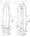
- FIG. 7Ais a side view of the expandable intervertebral fusion device constructed according to the present teachings, the expandable intervertebral fusion device shown in an unexpanded state.
- FIG. 7Bis a side view of the expandable intervertebral fusion device similar to FIG. 7A , the expandable intervertebral fusion device shown in a partially expanded state.
- FIG. 7Cis another expandable intervertebral fusion device in a fully expanded state.
- FIG. 8Ais a vertebral cross sectional taken along a midline of the expandable intervertebral fusion device, the expandable intervertebral fusion device shown in an unexpanded state.
- FIG. 8Bis a cross section similar to FIG. 8A , the expandable intervertebral fusion device shown in an expanded state.
- FIG. 8Cis a horizontal cross sectional taken along a midline of the expandable intervertebral fusion device, the expandable intervertebral fusion device shown in an expanded state.
- an expandable intervertebral fusion deviceis illustrated and generally identified at reference character 10 .
- the expandable intervertebral fusion device 10(or spinal implant) incorporates both expandable and lordosable capabilities.
- the present teachingsmay have alternative applications within the scope of the present teachings.
- the expandable intervertebral fusion device 10is shown to generally include a spacer or core 12 , an upper or superior endplate 14 A, a lower or inferior endplate 148 , and a locking mechanism 16 .
- the core 10 and the upper and lower endplates 14 A and 14 Bare cooperatively configured to translate relative to one another for providing an increased or expanded height to the expandable intervertebral fusion device 10 .
- the core 12 and the upper and lower endplates 14 A and 14 Bare also cooperatively configured to provide a lordotic angle for the expandable intervertebral fusion device.
- the expandable intervertebral fusion device 10is shown in a first state or unexpanded state intended for implantation in FIGS. 7A and 8A .
- FIG. 7Bthe expandable intervertebral fusion device 10 is shown in a second state or expanded state in which an unexpanded height H 1 of the device 10 has been increased to an expanded height H 2 .
- FIGS. 1, 7C, 8B and 8Cillustrate the expandable intervertebral fusion device in a third state or expanded and lordotic state.
- the upper and lower endplates 14 A and 14 Bare articulate relative to one another from the parallel orientation of the expanded state such that an angle of lordosis is established between the upper and lower endplates 14 A and 14 B.
- the second stateis technically a transition state between the first and third states. This state is not sustainable in that the device 10 cannot be locked in the second state.
- the core 12 of the device 10may be generally cuboid in shape and may be a proximal or trailing end 18 and a distal or leading end 20 .
- the device 10correspondingly includes a proximal or trailing end 22 and a distal or leading end 24 .
- the core 12may be constructed of polyetheretherketone or similar material. It will be appreciated, however, that alternative materials having suitable strength, durability and implantability characteristics may be used within the scope of the present teachings.
- the core 12 and the endplates 14 A and 14 Binclude corresponding inclined/declined plane surfaces.
- the plane surfacescooperate to distract the endplates 14 A and 14 B relative to the core 12 in response to relative horizontal translations.
- these inclined/declined plane surfacesmay cooperate to articulate the endplates 14 A and 14 B relative to the core 12 and thereby introduce a lordotic angle.
- the cooperating surfacesmay be disposed both proximally and distally relative to a longitudinal axis of the device 10 for purposes of supporting the endplates 14 A and 14 B.
- the core 12defines a forwardly tapering nose portion 26 .
- the nose portion 26tapers from a central portion 28 of the core 12 down to a reduced height tip 30 .
- the nose portion 26may include upper and lower surfaces that forwardly taper. Both of the upper and lower surfaces may be disposed at an angle of about 15°-45° to the horizontal. Lateral sides of the nose portion 26 may be arcuate in a horizontal plane.
- the central portion 28 of the core 12may define one or more openings vertically extending there through. As shown, the core 12 includes a first opening 32 and a second opening 34 .
- the first opening 32may allow for bone graft placement and containment to facilitate intervertebral fusion.
- the second opening 34may accommodate the locking mechanism 16 .
- Upper and lower surfaces 37 and 39 of the central portion 28 of the device 10may be generally horizontal and generally parallel to one another.
- the core 12includes a trailing portion 36 .
- the trailing portion 36may have a height greater than the height of the central portion 28 .
- upper and lower surfaces of the trailing portion 36are substantially identical.
- the upper and lower surfacesmay include a generally planar section 38 and a forwardly tapering section 40 .
- the forwardly tapering section 40may be on both lateral sides of the opening 32 .
- the forwardly tapering section 40may be angled similar to the nose portion 26 .
- the forwardly tapering sectionmay be disposed at an angle of approximately 30° relative to the horizontal. This angle can, however, vary.
- the generally planar sections 38declines (i.e., converges) slightly in a rearward direction.
- the core 12may include two substantially identical lateral sides 42 .
- Each lateral side 42may define upper and lower rails 44 .
- the upper and lower rails 44will be understood to be substantially identical to one another.
- Each rail 44may extend from proximate the trailing end 18 of the device 10 to about a mid-point of the length of the device 10 . At forward ends thereof, the rails 44 may be generally triangular in shape.
- Each side 42also includes a projection 46 disposed between the rails 44 .
- a track 45may be defined between the rails 44 .
- the projection 46forwardly extends from adjacent the trailing end 18 of the device 10 .
- a forward end of the projection 46includes upper and lower forwardly tapering surfaces 50 that converge to a tip.
- the forwardly tapering surfacesare generally aligned in a horizontal direction with the tapering section 40 of the trailing portion 36 .
- the forwardly tapering surfaces 50are similarly angled at approximately 30° relative to the horizontal.
- Each projection 46further includes upper and lower trailing surfaces 52 .
- the upper and lower trailing surfaces 52decline (i.e., converge) in a rearward direction.
- the trailing surfaces 52may decline at an angle of approximately 15° relative to the horizontal.
- the trailing surfacesmay be similarly angled to the generally planar sections 38 .
- a forward section 54 of each lateral side 42has an increased width such that a reduced width portion 56 is defined between the forward section 54 and the rails 44 .
- Each endplate 14 A and 14 Bmay include a bone engaging surface 57 for contacting a vertebral body.
- the bone engaging surfaces 57may conventionally include a plurality of ribs 58 or other structure to prevent movement of the device 10 after implantation.
- the bone engaging surfaces 57may be generally planar.
- the term generally planarwill encompass the slightly convex shape of the bone engaging surfaces 57 shown in the drawings.
- the bone engaging surfaces 57 of the endplates 14 A and 14 Bmay be oriented generally parallel to one another.
- Each endplate 14 A and 14 Bmay define an opening 60 which generally aligns with the first opening 32 of the core 12 and facilitates packing of the device 10 with bone graft material.
- Each endplate 14 A and 14 Bincludes a trailing end 62 and a leading end 64 .
- the endplates 14 A and 14 Bmay include a forwardly tapering nose portion 66 .
- Each endplate 14 A and 14 Bfurther includes a pair of lateral sides 68 .
- the lateral sides 68 of the upper endplate 14 Adownwardly extend.
- the lateral sides 68 of the lower endplate 14 Bupwardly extent.
- the lateral sides 68are generally parallel to one another and spaced apart to accommodate a width of the core 12 .
- Each lateral side 68is associated with an inwardly extending rail 70 .
- the rails 70extend forwardly from adjacent the trailing end 62 and each have a length smaller than a corresponding length of the reduced width portion 56 of the core 12 .
- each of the upper and lower endplates 14 A and 14 Bmay include a proximally disposed chamfer.
- the chamfer 63may extend across the width of the endplate 14 A and 14 B and may be angled similarly to the inclined surfaces of the tapering section 40 at an angle of 30° to the horizontal.
- each rail 70 of the endplates 14 A and 14 Bmay include an angled end 65 . Again, these ends 65 may be disposed at an angle of 30° to the horizontal.
- the upper angled surface of the nose portion 26 , the upwardly facing, tapering portion 40 , and the upwardly facing, forwardly tapering surfaces 50define a first plurality of superiorly facing inclined plane surfaces.
- the lower angled surface of the nose portion 26 , the downwardly facing, forwardly tapering surfaces 50 and the downwardly facing tapering portion 40define a first plurality of inferiorly facing inclined plane surfaces.
- the upper and lower endplates 14 A and 14 Binclude a second plurality of inferiorly facing inclined plane surfaces and a second plurality of superiorly, respectively.
- the second plurality of inferiorly facing inclined plane surfaces and second plurality of superiorlyare defined at respective proximal ends by the chamfered surface 63 and angled ends 65 of the rails 70 .
- the upwardly facing ones of the trailing surfaces 52define a first plurality of superiorly facing declined surfaces for slidably engaging the superior endplate to articulate the endplate relative to the core in response to translation therebetween.
- the downwardly facing one of the trailing surfaces 52define a first plurality of inferiorly facing declined plane surfaces for slidably engaging the inferior endplate to articulate the endplate relative to the core in response to translation therebetween.
- the device 10is assembled by first inserting the locking mechanism 16 in the second opening 34 .
- the upper and lower endplates 14 A and 14 Bmay be attached by vertically inserting the rails 70 into the corresponding reduced width portion 56 of the core 12 .
- the core 12is then forwardly translated relative to the endplates 14 A and 14 B such that the rails 70 are positioned between the rails 44 and in the track 45 of the core 12 .
- an axial (anteroposterior position of the endplates 14 A and 14 Bis maintained.
- the fully assembled device 10is shown in FIG. 7A , for example. In this first, or contracted or non-expanded state, the device 10 is ready for implantation.
- the increased height trailing portion 36 of the core 12may be located completely rearward of the endplates 14 A and 14 B.
- the device 10may be intraoperatively articulated to a second state (see FIG. 7B , for example) in which the device 10 has a second height H 2 which is greater than a first height H 1 of the device 10 in the first state.
- a portion of the intervertebral spacemay be distracted.
- the endplates 14 A and 14 Bmay be generally parallel in the second state.
- the first height H 1may be approximately 6 mm and the second height H 2 may be approximately 8 mm. These dimensions may range from approximately 6 mm to approximately 15 mm, however. Those skilled in the art will appreciate that these dimensions are merely exemplary and may be readily modified within the scope of the present teachings.
- the device 10may be intraoperatively articulated from the first state to the second state by horizontal translation of the endplates 14 A and 14 B relative to the core 12 .
- the core 12is translated forwardly relative to the endplates 14 A and 14 B from the first state to the second state.
- the endplates 14 A and 14 Bmay be horizontally translated rearwardly relative to the core 12 .
- the tool 80For purposes of translating the core 12 relative to the upper and lower endplates 14 A and 14 B, the tool may include a hollow shaft engaging a threaded opening 82 in the trailing end 22 of the core 12 and a rod which passes through the hollow shaft. The rod may terminate in a T-shape. As the end of the rod is inserted into the device 10 , the T-shape passes below a tab 81 carried by each of the upper and lower endplates 14 A and 14 B. After the T-shape passes the tab, the rod may be rotated 90° and retracted for rearwardly advancing the core 12 relative to the endplates 14 A and 14 B.
- the locking mechanism 16is disposed in the second opening 34 of the core 12 and carried by the core 12 .
- the locking mechanism 16is generally shown to include a pair of pins 72 , upper and lower blocks 74 and an actuation member 76 .
- the pins 72allow the blocks 74 to translate relative to one another between a contracted state (as shown in FIG. 68 , for example) and an expanded state (as shown in FIG. 6C , for example).
- the actuation member 76is rotatably captured between the blocks 74 and may be rotated by a tool 80 (see, FIG. 6C ).
- the actuation member 76may generally include a head 83 , a tip 84 and a central portion 86 therebetween.
- the central portion 86may be generally planar such that in a first orientation (see, FIG. 8A ), the central portion 86 is horizontally oriented and the blocks 74 are in a contracted state, and in a second orientation (see, FIG. 8B ), the central portion 86 is vertically oriented and the blocks 74 are in an expanded state.
- the nose portion 26 of the core 12forces the leading ends 64 of the endplates 14 A and 14 B apart.
- upper and lower facing angled surfaces of the nose portion 26slidably engage the ramped surface 51 (see FIG. 4B ) on the underside of each endplate 14 A and 14 B.
- the tapered section 40slide relative to the upper and lower forwardly tapering surfaces 50 of the core 12 force the trailing ends 62 of the endplates 14 A and 14 B apart.
- the tapering surfaces 50engage angled ends 65 of the rails 70 . In this manner, load is distributed between the cooperating surfaces.
- the slopes of the nose portion 26 , the tapered section 40 and the upper and lower forwardly tapering surfaces 50 , the angled ends 65 of the rails 70 and the chamfer 63are substantively identical such that the endplates 14 A and 14 B remain parallel in the second state. It will be appreciated that the endplates 14 A and 14 B are distracted in parallel directions.
- the tapering section 40engages the chamfered surface 63 (see FIG. 4B ) on the underside of the endplates 14 A and 14 B.
- a lordotic angleis defined between the upper and lower endplates 14 A and 14 B.
- This lordotic anglemay range from approximately 8° to approximately 12°. In the embodiment illustrated, the lordotic angle is approximately 8°. It will be understood that the lordotic angle may be changed within the scope of the present invention.
- the locking mechanism 16may be intraoperatively actuated to prevent relative translation between the core 12 and the endplates 14 A and 14 B.
- the actuation device 76may be rotated by the tool 80 to vertically orient the generally planar central portion 86 .
- the blocks 74are received within laterally extending grooves 90 defined on the inner sides of the endplates 14 A and 14 B.
- an expandable intervertebral fusion devicethat allows for vertical, parallel expansion (i.e., increased device height) by way of corresponding inclined plane features between the two endplate components and the spacer component at both their proximal (back) and distal (front) ends, as they translate relative to (towards) one another in the horizontal/transverse plane.
- the incline plane features at the proximal (back) end of the spacer componenttransition into reverse incline (decline) plane features.
- the corresponding incline plane features at the distal (front) end of device, between both the endplate and spacer componentscontinue.
- the endplate componentsangulate, driven by the reverse incline (decline) plane features at the proximal (back) end of the spacer component and the corresponding incline plane features at the distal (front) end of the device.
- the expandable intervertebral fusion devicemay be inserted in the same manner and using the same general surgical technique as a conventional fixed-geometry intervertebral body fusion device.
- the combined expandable-lordosable devicecollapses (vertically) to an exceptionally low profile (e.g., 6 mm), allowing it to be more easily placed into a small or collapsed intervertebral space. It also further facilities minimally invasive surgery by way of its low initial (collapsed and nonlordotic) profile.
- Spatially relative termssuch as “superior,” “inferior,” “lower,” “upper,” “proximal,” “distal” and the like, may be used herein for ease of description to describe one element or feature's relationship to another element(s) or feature(s) as illustrated in the figures. Spatially relative terms may be intended to encompass different orientations of the device in use or operation in addition to the orientation depicted in the figures. For example, if the device in the figures is turned over, elements described as “superior” or “upper” would then be as oriented “inferior” or “lower” elements.
- the term “generally” as used in the terms “generally horizontal,” “generally parallel” and the likeshall be understood to be within ten degrees (10°) of the modified term, and preferably with five degrees (5°) of the modified term.
Landscapes
- Health & Medical Sciences (AREA)
- Engineering & Computer Science (AREA)
- Biomedical Technology (AREA)
- Neurology (AREA)
- Orthopedic Medicine & Surgery (AREA)
- Cardiology (AREA)
- Oral & Maxillofacial Surgery (AREA)
- Transplantation (AREA)
- Heart & Thoracic Surgery (AREA)
- Vascular Medicine (AREA)
- Life Sciences & Earth Sciences (AREA)
- Animal Behavior & Ethology (AREA)
- General Health & Medical Sciences (AREA)
- Public Health (AREA)
- Veterinary Medicine (AREA)
- Prostheses (AREA)
Abstract
Description
Claims (20)
Priority Applications (1)
| Application Number | Priority Date | Filing Date | Title |
|---|---|---|---|
| US16/374,153US11065129B2 (en) | 2014-06-02 | 2019-04-03 | Expandable intervertebral fusion device |
Applications Claiming Priority (3)
| Application Number | Priority Date | Filing Date | Title |
|---|---|---|---|
| US201462006715P | 2014-06-02 | 2014-06-02 | |
| US14/724,968US10278831B2 (en) | 2014-06-02 | 2015-05-29 | Expandable intervertebral fusion device |
| US16/374,153US11065129B2 (en) | 2014-06-02 | 2019-04-03 | Expandable intervertebral fusion device |
Related Parent Applications (1)
| Application Number | Title | Priority Date | Filing Date |
|---|---|---|---|
| US14/724,968ContinuationUS10278831B2 (en) | 2014-06-02 | 2015-05-29 | Expandable intervertebral fusion device |
Publications (2)
| Publication Number | Publication Date |
|---|---|
| US20190231552A1 US20190231552A1 (en) | 2019-08-01 |
| US11065129B2true US11065129B2 (en) | 2021-07-20 |
Family
ID=53491669
Family Applications (2)
| Application Number | Title | Priority Date | Filing Date |
|---|---|---|---|
| US14/724,968Expired - Fee RelatedUS10278831B2 (en) | 2014-06-02 | 2015-05-29 | Expandable intervertebral fusion device |
| US16/374,153Expired - Fee RelatedUS11065129B2 (en) | 2014-06-02 | 2019-04-03 | Expandable intervertebral fusion device |
Family Applications Before (1)
| Application Number | Title | Priority Date | Filing Date |
|---|---|---|---|
| US14/724,968Expired - Fee RelatedUS10278831B2 (en) | 2014-06-02 | 2015-05-29 | Expandable intervertebral fusion device |
Country Status (2)
| Country | Link |
|---|---|
| US (2) | US10278831B2 (en) |
| WO (1) | WO2015187569A1 (en) |
Cited By (17)
| Publication number | Priority date | Publication date | Assignee | Title |
|---|---|---|---|---|
| US11376134B1 (en) | 2020-11-05 | 2022-07-05 | Warsaw Orthopedic, Inc. | Dual expanding spinal implant, system, and method of use |
| US11395743B1 (en) | 2021-05-04 | 2022-07-26 | Warsaw Orthopedic, Inc. | Externally driven expandable interbody and related methods |
| US11517363B2 (en) | 2020-11-05 | 2022-12-06 | Warsaw Orthopedic, Inc. | Screw driver and complimentary screws |
| US11517443B2 (en) | 2020-11-05 | 2022-12-06 | Warsaw Orthopedic, Inc. | Dual wedge expandable implant, system and method of use |
| US11612499B2 (en) | 2021-06-24 | 2023-03-28 | Warsaw Orthopedic, Inc. | Expandable interbody implant |
| US11638653B2 (en) | 2020-11-05 | 2023-05-02 | Warsaw Orthopedic, Inc. | Surgery instruments with a movable handle |
| US11752007B2 (en) | 2021-01-05 | 2023-09-12 | FloSpine, LLC | Expandable intervertebral implant system and method |
| US11806250B2 (en) | 2018-02-22 | 2023-11-07 | Warsaw Orthopedic, Inc. | Expandable spinal implant system and method of using same |
| US11833059B2 (en) | 2020-11-05 | 2023-12-05 | Warsaw Orthopedic, Inc. | Expandable inter-body device, expandable plate system, and associated methods |
| US11963881B2 (en) | 2020-11-05 | 2024-04-23 | Warsaw Orthopedic, Inc. | Expandable inter-body device, system, and method |
| US12121453B2 (en) | 2020-11-05 | 2024-10-22 | Warsaw Orthopedic, Inc. | Dual wedge expandable implant with eyelets, system, and method of use |
| US12171439B2 (en) | 2020-11-05 | 2024-12-24 | Warsaw Orthopedic, Inc. | Protected drill |
| US12239544B2 (en) | 2020-11-05 | 2025-03-04 | Warsaw Orthopedic, Inc. | Rhomboid shaped implants |
| US12295865B2 (en) | 2021-06-24 | 2025-05-13 | Warsaw Orthopedic, Inc. | Expandable interbody implant and corresponding inserter |
| US12318308B2 (en) | 2020-11-05 | 2025-06-03 | Warsaw Orthopedic, Inc. | Dual expandable inter-body device |
| US12414863B2 (en) | 2021-06-24 | 2025-09-16 | Warsaw Orthopedic, Inc. | Expandable interbody implant and corresponding surgical tool |
| US12440349B2 (en) | 2022-02-04 | 2025-10-14 | Warsaw Orthopedic, Inc. | Expandable interbody implant and breakoff screw |
Families Citing this family (97)
| Publication number | Priority date | Publication date | Assignee | Title |
|---|---|---|---|---|
| US11103366B2 (en) | 2009-10-15 | 2021-08-31 | Globus Medical, Inc. | Expandable fusion device and method of installation thereof |
| US10098758B2 (en) | 2009-10-15 | 2018-10-16 | Globus Medical, Inc. | Expandable fusion device and method of installation thereof |
| US8685098B2 (en) | 2010-06-25 | 2014-04-01 | Globus Medical, Inc. | Expandable fusion device and method of installation thereof |
| US11344430B2 (en) | 2009-10-15 | 2022-05-31 | Globus Medical, Inc. | Expandable fusion device and method of installation thereof |
| US9913726B2 (en) | 2010-02-24 | 2018-03-13 | Globus Medical, Inc. | Expandable intervertebral spacer and method of posterior insertion thereof |
| US8870880B2 (en) | 2010-04-12 | 2014-10-28 | Globus Medical, Inc. | Angling inserter tool for expandable vertebral implant |
| US9597200B2 (en) | 2010-06-25 | 2017-03-21 | Globus Medical, Inc | Expandable fusion device and method of installation thereof |
| US10945858B2 (en) | 2010-09-03 | 2021-03-16 | Globus Medical, Inc. | Expandable interspinous process fixation device |
| US9907673B2 (en)* | 2010-09-03 | 2018-03-06 | Globus Medical, Inc. | Expandable fusion device and method of installation thereof |
| US8632595B2 (en) | 2010-09-03 | 2014-01-21 | Globus Medical, Inc. | Expandable fusion device and method of installation thereof |
| US10709573B2 (en) | 2010-09-03 | 2020-07-14 | Globus Medical Inc. | Expandable fusion device and method of installation thereof |
| US9566168B2 (en) | 2010-09-03 | 2017-02-14 | Globus Medical, Inc. | Expandable fusion device and method of installation thereof |
| US12059358B2 (en) | 2010-09-03 | 2024-08-13 | Globus Medical Inc. | Expandable fusion device and method of installation thereof |
| US10835387B2 (en) | 2010-09-03 | 2020-11-17 | Globus Medical Inc. | Expandable fusion device and method of installation thereof |
| US10842644B2 (en) | 2010-09-03 | 2020-11-24 | Globus Medical, Inc. | Expandable fusion device and method of installation thereof |
| US10869768B2 (en) | 2010-09-03 | 2020-12-22 | Globus Medical Inc. | Expandable fusion device and method of installation thereof |
| US11446162B2 (en) | 2010-09-03 | 2022-09-20 | Globus Medical, Inc. | Expandable fusion device and method of installation thereof |
| US10779957B2 (en) | 2010-09-03 | 2020-09-22 | Globus Medical, Inc. | Expandable fusion device and method of installation thereof |
| US9351848B2 (en) | 2010-09-03 | 2016-05-31 | Globus Medical, Inc. | Expandable fusion device and method of installation thereof |
| US11793654B2 (en) | 2010-09-03 | 2023-10-24 | Globus Medical, Inc. | Expandable fusion device and method of installation thereof |
| US12370057B2 (en) | 2010-09-03 | 2025-07-29 | Globus Medical, Inc. | Expandable fusion device and method of installation thereof |
| US10758367B2 (en) | 2010-09-03 | 2020-09-01 | Globus Medical Inc. | Expandable fusion device and method of installation thereof |
| US8864833B2 (en) | 2011-09-30 | 2014-10-21 | Globus Medical, Inc. | Expandable fusion device and method of installation thereof |
| US9044342B2 (en) | 2012-05-30 | 2015-06-02 | Globus Medical, Inc. | Expandable interbody spacer |
| US10350081B2 (en) | 2012-12-11 | 2019-07-16 | Globus Medical, Inc. | Expandable vertebral implant |
| US8663332B1 (en) | 2012-12-13 | 2014-03-04 | Ouroboros Medical, Inc. | Bone graft distribution system |
| US9011493B2 (en) | 2012-12-31 | 2015-04-21 | Globus Medical, Inc. | Spinous process fixation system and methods thereof |
| US9782265B2 (en) | 2013-02-15 | 2017-10-10 | Globus Medical, Inc | Articulating and expandable vertebral implant |
| US10117754B2 (en) | 2013-02-25 | 2018-11-06 | Globus Medical, Inc. | Expandable intervertebral implant |
| US9204972B2 (en) | 2013-03-01 | 2015-12-08 | Globus Medical, Inc. | Articulating expandable intervertebral implant |
| US10004607B2 (en) | 2013-03-01 | 2018-06-26 | Globus Medical, Inc. | Articulating expandable intervertebral implant |
| US9186258B2 (en) | 2013-03-15 | 2015-11-17 | Globus Medical, Inc. | Expandable intervertebral implant |
| US9149367B2 (en) | 2013-03-15 | 2015-10-06 | Globus Medical Inc | Expandable intervertebral implant |
| US9572677B2 (en) | 2013-03-15 | 2017-02-21 | Globus Medical, Inc. | Expandable intervertebral implant |
| US9233009B2 (en) | 2013-03-15 | 2016-01-12 | Globus Medical, Inc. | Expandable intervertebral implant |
| WO2014145766A1 (en)* | 2013-03-15 | 2014-09-18 | Paradigm Spine, Llc | Modular, customizable spine stabilization system |
| US9186259B2 (en) | 2013-09-09 | 2015-11-17 | Ouroboros Medical, Inc. | Expandable trials |
| US9839528B2 (en) | 2014-02-07 | 2017-12-12 | Globus Medical, Inc. | Variable lordosis spacer and related methods of use |
| US9662224B2 (en) | 2014-02-07 | 2017-05-30 | Globus Medical, Inc. | Variable lordosis spacer and related methods of use |
| US10278831B2 (en) | 2014-06-02 | 2019-05-07 | Zimmer Biomet Spine, Inc. | Expandable intervertebral fusion device |
| US9901459B2 (en) | 2014-12-16 | 2018-02-27 | Globus Medical, Inc. | Expandable fusion devices and methods of installation thereof |
| US9060876B1 (en) | 2015-01-20 | 2015-06-23 | Ouroboros Medical, Inc. | Stabilized intervertebral scaffolding systems |
| US9814602B2 (en) | 2015-05-14 | 2017-11-14 | Globus Medical, Inc. | Expandable intervertebral implants and methods of installation thereof |
| US10433975B2 (en) | 2015-05-21 | 2019-10-08 | Globus Medical, Inc. | Device and method for deployment of an anchoring device for intervertebral spinal fusion |
| US10765532B2 (en) | 2015-05-21 | 2020-09-08 | Globus Medical, Inc. | Device and method for deployment of an anchoring device for intervertebral spinal fusion |
| US10631997B2 (en) | 2015-05-21 | 2020-04-28 | Globus Medical, Inc. | Device and method for deployment of an anchoring device for intervertebral spinal fusion |
| US10016282B2 (en) | 2015-07-17 | 2018-07-10 | Globus Medical, Inc. | Intervertebral spacer and plate |
| US11045326B2 (en) | 2015-07-17 | 2021-06-29 | Global Medical Inc | Intervertebral spacer and plate |
| US10500061B2 (en)* | 2015-08-13 | 2019-12-10 | K2M, Inc. | Adjustable spinal implant |
| US10034768B2 (en) | 2015-09-02 | 2018-07-31 | Globus Medical, Inc. | Implantable systems, devices and related methods |
| US10137009B2 (en) | 2015-09-02 | 2018-11-27 | Globus Medical, Inc. | Expandable intervertebral fusion devices and methods of installation thereof |
| US10219914B2 (en) | 2015-11-10 | 2019-03-05 | Globus Medical, Inc. | Stabilized expandable intervertebral spacer |
| US10524928B2 (en) | 2015-12-15 | 2020-01-07 | Globus Medical, Inc | Stabilized intervertebral spacer |
| US10369004B2 (en) | 2015-12-16 | 2019-08-06 | Globus Medical, Inc. | Expandable intervertebralspacer |
| US10076423B2 (en) | 2016-01-04 | 2018-09-18 | Warsaw Orthopedic, Inc. | Pivoting wedge expanding spinal implant and method of implanting same |
| US9974575B2 (en) | 2016-02-02 | 2018-05-22 | Globus Medical, Inc. | Expandable spinal fixation system |
| US9974662B2 (en) | 2016-06-29 | 2018-05-22 | Globus Medical, Inc. | Expandable fusion device and method of installation thereof |
| US10052215B2 (en) | 2016-06-29 | 2018-08-21 | Globus Medical, Inc. | Expandable fusion device and method of installation thereof |
| US12161563B2 (en) | 2016-09-14 | 2024-12-10 | Globus Medical, Inc. | Systems and methods for expandable corpectomy spacer implantation |
| US11596526B2 (en) | 2016-09-14 | 2023-03-07 | Globus Medical Inc. | Systems and methods for expandable corpectomy spacer implantation |
| US9883953B1 (en) | 2016-09-21 | 2018-02-06 | Integrity Implants Inc. | Stabilized laterovertically-expanding fusion cage systems with tensioner |
| JP7085554B2 (en) | 2017-01-10 | 2022-06-16 | インテグリティ インプランツ インコーポレイテッド | Deployable intervertebral fusion device |
| EP3421013B1 (en)* | 2017-06-28 | 2025-02-26 | Globus Medical, Inc. | Expandable fusion device |
| CN111031969A (en) | 2017-07-24 | 2020-04-17 | 整体植入有限公司 | Surgical implants and related methods |
| US10709578B2 (en) | 2017-08-25 | 2020-07-14 | Integrity Implants Inc. | Surgical biologics delivery system and related methods |
| US10709569B2 (en) | 2017-11-09 | 2020-07-14 | Globus Medical, Inc. | Expandable intervertebral implant |
| US10575962B2 (en)* | 2017-11-20 | 2020-03-03 | Warsaw Orthopedic, Inc. | Spinal implant |
| JP7572857B2 (en) | 2018-03-01 | 2024-10-24 | インテグリティ インプランツ インコーポレイテッド | Expandable Fusion Device with Independent Deployment System |
| FR3091648B1 (en)* | 2019-01-10 | 2020-12-25 | Razian Hassan | Intervertebral cage |
| US11179242B2 (en) | 2019-07-18 | 2021-11-23 | Globus Medical, Inc. | Expanding intervertebral implants |
| US11259933B2 (en) | 2019-09-06 | 2022-03-01 | Globus Medical Inc. | Expandable motion preservation spacer |
| TWI736010B (en) | 2019-11-08 | 2021-08-11 | 財團法人工業技術研究院 | Spinal intervertebral body fusion device |
| WO2021127635A1 (en) | 2019-12-19 | 2021-06-24 | FloSpine, LLC | Expandable intervertebral implant |
| US11337824B2 (en) | 2019-12-20 | 2022-05-24 | Globus Medical, Inc. | Stabilizing vertebrae with articulating implants |
| US11154405B2 (en) | 2020-01-23 | 2021-10-26 | Globus Medical, Inc. | Articulating expandable interbody fusions devices |
| US11191650B2 (en)* | 2020-02-03 | 2021-12-07 | Globus Medical Inc. | Expandable fusions devices, instruments, and methods thereof |
| US11298240B2 (en) | 2020-06-16 | 2022-04-12 | Globus Medical, Inc. | Expanding intervertebral implants |
| US11166825B1 (en) | 2020-07-01 | 2021-11-09 | Warsaw Orthopedic, Inc. | Spinal implant |
| US11357640B2 (en) | 2020-07-08 | 2022-06-14 | Globus Medical Inc. | Expandable interbody fusions devices |
| US11491020B2 (en) | 2020-07-09 | 2022-11-08 | Globus Medical, Inc. | Articulating and expandable interbody fusions devices |
| US20220117749A1 (en) | 2020-07-09 | 2022-04-21 | Globus Medical, Inc. | Intradiscal fixation systems |
| EP4171448A4 (en) | 2020-07-20 | 2025-02-12 | Integrity Implants Inc. | EXPANDABLE FUSION DEVICE WITH INDEPENDENT EXPANSION SYSTEMS |
| US11285014B1 (en) | 2020-11-05 | 2022-03-29 | Warsaw Orthopedic, Inc. | Expandable inter-body device, system, and method |
| US11291554B1 (en) | 2021-05-03 | 2022-04-05 | Medtronic, Inc. | Unibody dual expanding interbody implant |
| EP4312890A1 (en) | 2021-04-02 | 2024-02-07 | Nuvasive, Inc. | Expansion driver |
| JP2024514536A (en) | 2021-04-04 | 2024-04-02 | ニューヴェイジヴ,インコーポレイテッド | expandable implant |
| US12268614B2 (en) | 2021-06-24 | 2025-04-08 | Warsaw Orthopedic, Inc. | Interbody implant with adjusting shims |
| US11730608B2 (en) | 2021-07-13 | 2023-08-22 | Warsaw Orthopedic, Inc. | Monoblock expandable interbody implant |
| WO2023285675A1 (en) | 2021-07-16 | 2023-01-19 | Blue Ocean Spine Gmbh | Adjustable intervertebral cage, associated instrument and manufacturing process therefor |
| US12324748B2 (en) | 2021-12-02 | 2025-06-10 | Globus Medical, Inc. | Expandable fusion device with integrated deployable retention spikes |
| US11712346B2 (en) | 2021-12-02 | 2023-08-01 | Globus Medical, Inc. | Expandable fusion device with integrated deployable retention spikes |
| US11850163B2 (en) | 2022-02-01 | 2023-12-26 | Warsaw Orthopedic, Inc. | Interbody implant with adjusting shims |
| US12011364B2 (en) | 2022-06-15 | 2024-06-18 | Globus Medical, Inc | Expandable footprint implant |
| US11883080B1 (en) | 2022-07-13 | 2024-01-30 | Globus Medical, Inc | Reverse dynamization implants |
| US12396867B2 (en) | 2023-03-21 | 2025-08-26 | Globus Medical, Inc. | Expandable footprint implant |
| US12427038B2 (en) | 2023-06-27 | 2025-09-30 | Globus Medical Inc. | Expandable intervertebral interbody implants |
| US12396866B2 (en) | 2023-09-27 | 2025-08-26 | Globus Medical, Inc. | Expandable anterior lumbar implants |
Citations (6)
| Publication number | Priority date | Publication date | Assignee | Title |
|---|---|---|---|---|
| US20060122701A1 (en)* | 2004-11-23 | 2006-06-08 | Kiester P D | Posterior lumbar interbody fusion expandable cage with lordosis and method of deploying the same |
| US20120059475A1 (en)* | 2010-09-03 | 2012-03-08 | Mark Weiman | Expandable Fusion Device and Method of Installation Thereof |
| US20130158664A1 (en) | 2011-12-19 | 2013-06-20 | Warsaw Orthopedic, Inc. | Expandable interbody implant and methods of use |
| US20140094916A1 (en) | 2010-09-03 | 2014-04-03 | Chad Glerum | Expandable Fusion Device and Method of Installation Thereof |
| WO2015187569A1 (en) | 2014-06-02 | 2015-12-10 | Lanx, Inc. | Expandable intervertebral fusion device |
| US20160022438A1 (en) | 2013-03-15 | 2016-01-28 | Lanx, Inc. | Expandable fusion cage system |
- 2015
- 2015-05-29USUS14/724,968patent/US10278831B2/ennot_activeExpired - Fee Related
- 2015-06-01WOPCT/US2015/033559patent/WO2015187569A1/enactiveApplication Filing
- 2019
- 2019-04-03USUS16/374,153patent/US11065129B2/ennot_activeExpired - Fee Related
Patent Citations (8)
| Publication number | Priority date | Publication date | Assignee | Title |
|---|---|---|---|---|
| US20060122701A1 (en)* | 2004-11-23 | 2006-06-08 | Kiester P D | Posterior lumbar interbody fusion expandable cage with lordosis and method of deploying the same |
| US20120059475A1 (en)* | 2010-09-03 | 2012-03-08 | Mark Weiman | Expandable Fusion Device and Method of Installation Thereof |
| US20140094916A1 (en) | 2010-09-03 | 2014-04-03 | Chad Glerum | Expandable Fusion Device and Method of Installation Thereof |
| US20130158664A1 (en) | 2011-12-19 | 2013-06-20 | Warsaw Orthopedic, Inc. | Expandable interbody implant and methods of use |
| US20160022438A1 (en) | 2013-03-15 | 2016-01-28 | Lanx, Inc. | Expandable fusion cage system |
| WO2015187569A1 (en) | 2014-06-02 | 2015-12-10 | Lanx, Inc. | Expandable intervertebral fusion device |
| US20150374508A1 (en) | 2014-06-02 | 2015-12-31 | Lanx, Inc. | Expandable intervertebral fusion device |
| US10278831B2 (en) | 2014-06-02 | 2019-05-07 | Zimmer Biomet Spine, Inc. | Expandable intervertebral fusion device |
Non-Patent Citations (11)
Cited By (23)
| Publication number | Priority date | Publication date | Assignee | Title |
|---|---|---|---|---|
| US11806250B2 (en) | 2018-02-22 | 2023-11-07 | Warsaw Orthopedic, Inc. | Expandable spinal implant system and method of using same |
| US12036132B2 (en) | 2018-02-22 | 2024-07-16 | Warsaw Orthopedic, Inc. | Expandable spinal implant system and method of using same |
| US12121453B2 (en) | 2020-11-05 | 2024-10-22 | Warsaw Orthopedic, Inc. | Dual wedge expandable implant with eyelets, system, and method of use |
| US11517363B2 (en) | 2020-11-05 | 2022-12-06 | Warsaw Orthopedic, Inc. | Screw driver and complimentary screws |
| US11564724B2 (en) | 2020-11-05 | 2023-01-31 | Warsaw Orthopedic, Inc. | Expandable inter-body device, system and method |
| US12364529B2 (en) | 2020-11-05 | 2025-07-22 | Warsaw Orthopedic, Inc. | Expandable inter-body device, system, and method |
| US11617658B2 (en) | 2020-11-05 | 2023-04-04 | Warsaw Orthopedic, Inc. | Expandable inter-body device, system and method |
| US11638653B2 (en) | 2020-11-05 | 2023-05-02 | Warsaw Orthopedic, Inc. | Surgery instruments with a movable handle |
| US12239544B2 (en) | 2020-11-05 | 2025-03-04 | Warsaw Orthopedic, Inc. | Rhomboid shaped implants |
| US12318308B2 (en) | 2020-11-05 | 2025-06-03 | Warsaw Orthopedic, Inc. | Dual expandable inter-body device |
| US11833059B2 (en) | 2020-11-05 | 2023-12-05 | Warsaw Orthopedic, Inc. | Expandable inter-body device, expandable plate system, and associated methods |
| US11963881B2 (en) | 2020-11-05 | 2024-04-23 | Warsaw Orthopedic, Inc. | Expandable inter-body device, system, and method |
| US11969196B2 (en) | 2020-11-05 | 2024-04-30 | Warsaw Orthopedic, Inc. | Expandable inter-body device, system, and method |
| US11517443B2 (en) | 2020-11-05 | 2022-12-06 | Warsaw Orthopedic, Inc. | Dual wedge expandable implant, system and method of use |
| US12053392B2 (en) | 2020-11-05 | 2024-08-06 | Warsaw Orthopedic, Inc. | Expandable inter-body device, expandable plate system, and associated methods |
| US11376134B1 (en) | 2020-11-05 | 2022-07-05 | Warsaw Orthopedic, Inc. | Dual expanding spinal implant, system, and method of use |
| US12171439B2 (en) | 2020-11-05 | 2024-12-24 | Warsaw Orthopedic, Inc. | Protected drill |
| US11752007B2 (en) | 2021-01-05 | 2023-09-12 | FloSpine, LLC | Expandable intervertebral implant system and method |
| US11395743B1 (en) | 2021-05-04 | 2022-07-26 | Warsaw Orthopedic, Inc. | Externally driven expandable interbody and related methods |
| US12295865B2 (en) | 2021-06-24 | 2025-05-13 | Warsaw Orthopedic, Inc. | Expandable interbody implant and corresponding inserter |
| US11612499B2 (en) | 2021-06-24 | 2023-03-28 | Warsaw Orthopedic, Inc. | Expandable interbody implant |
| US12414863B2 (en) | 2021-06-24 | 2025-09-16 | Warsaw Orthopedic, Inc. | Expandable interbody implant and corresponding surgical tool |
| US12440349B2 (en) | 2022-02-04 | 2025-10-14 | Warsaw Orthopedic, Inc. | Expandable interbody implant and breakoff screw |
Also Published As
| Publication number | Publication date |
|---|---|
| US20190231552A1 (en) | 2019-08-01 |
| US20150374508A1 (en) | 2015-12-31 |
| WO2015187569A1 (en) | 2015-12-10 |
| US10278831B2 (en) | 2019-05-07 |
Similar Documents
| Publication | Publication Date | Title |
|---|---|---|
| US11065129B2 (en) | Expandable intervertebral fusion device | |
| US12433759B2 (en) | Expandable intervertebral spacer | |
| US12083025B2 (en) | Intervertebral cages with integrated expansion and angular adjustment mechanism | |
| US11766341B2 (en) | Expandable fusion device for positioning between adjacent vertebral bodies | |
| US11759331B2 (en) | Stabilized expandable intervertebral spacer | |
| US12396865B2 (en) | Angularly adjustable intervertebral cages with integrated ratchet assembly | |
| US11766340B2 (en) | Articulating expandable intervertebral implant | |
| US9603717B2 (en) | System and method for an expandable intervertebral implant | |
| US9387089B2 (en) | Expandable anterior lumbar interbody fusion device | |
| US9204973B2 (en) | Laterally expandable interbody fusion cage | |
| US20120197405A1 (en) | Intervertebral implant | |
| CN101198298A (en) | Expandable spinal implant and related placement procedure | |
| CN115381606B (en) | An intervertebral fusion cage capable of being expanded at an angle and a spinal implant system thereof | |
| US20230293312A1 (en) | Articulating expandable intervertebral implant |
Legal Events
| Date | Code | Title | Description |
|---|---|---|---|
| FEPP | Fee payment procedure | Free format text:ENTITY STATUS SET TO UNDISCOUNTED (ORIGINAL EVENT CODE: BIG.); ENTITY STATUS OF PATENT OWNER: LARGE ENTITY | |
| STPP | Information on status: patent application and granting procedure in general | Free format text:RESPONSE TO NON-FINAL OFFICE ACTION ENTERED AND FORWARDED TO EXAMINER | |
| STPP | Information on status: patent application and granting procedure in general | Free format text:NOTICE OF ALLOWANCE MAILED -- APPLICATION RECEIVED IN OFFICE OF PUBLICATIONS | |
| STPP | Information on status: patent application and granting procedure in general | Free format text:PUBLICATIONS -- ISSUE FEE PAYMENT VERIFIED | |
| STCF | Information on status: patent grant | Free format text:PATENTED CASE | |
| CC | Certificate of correction | ||
| AS | Assignment | Owner name:JPMORGAN CHASE BANK, N.A., AS ADMINISTRATIVE AGENT, NEW YORK Free format text:SECURITY INTEREST;ASSIGNORS:BIOMET 3I, LLC;EBI, LLC;ZIMMER BIOMET SPINE, INC.;AND OTHERS;REEL/FRAME:059293/0213 Effective date:20220228 | |
| AS | Assignment | Owner name:CERBERUS BUSINESS FINANCE AGENCY, LLC, NEW YORK Free format text:GRANT OF A SECURITY INTEREST -- PATENTS;ASSIGNORS:ZIMMER BIOMET SPINE, LLC;EBI, LLC;REEL/FRAME:066970/0806 Effective date:20240401 | |
| AS | Assignment | Owner name:ZIMMER BIOMET SPINE, LLC (F/K/A ZIMMER BIOMET SPINE, INC.), COLORADO Free format text:RELEASE BY SECURED PARTY;ASSIGNOR:JPMORGAN CHASE BANK, N.A.;REEL/FRAME:066973/0833 Effective date:20240401 Owner name:EBI, LLC, NEW JERSEY Free format text:RELEASE BY SECURED PARTY;ASSIGNOR:JPMORGAN CHASE BANK, N.A.;REEL/FRAME:066973/0833 Effective date:20240401 | |
| AS | Assignment | Owner name:ZIMMER BIOMET SPINE, LLC, COLORADO Free format text:CHANGE OF NAME;ASSIGNOR:ZIMMER BIOMET SPINE, INC.;REEL/FRAME:069772/0121 Effective date:20240220 Owner name:HIGHRIDGE MEDICAL, LLC, COLORADO Free format text:CHANGE OF NAME;ASSIGNOR:ZIMMER BIOMET SPINE, LLC;REEL/FRAME:069772/0248 Effective date:20240405 | |
| FEPP | Fee payment procedure | Free format text:MAINTENANCE FEE REMINDER MAILED (ORIGINAL EVENT CODE: REM.); ENTITY STATUS OF PATENT OWNER: LARGE ENTITY | |
| LAPS | Lapse for failure to pay maintenance fees | Free format text:PATENT EXPIRED FOR FAILURE TO PAY MAINTENANCE FEES (ORIGINAL EVENT CODE: EXP.); ENTITY STATUS OF PATENT OWNER: LARGE ENTITY | |
| STCH | Information on status: patent discontinuation | Free format text:PATENT EXPIRED DUE TO NONPAYMENT OF MAINTENANCE FEES UNDER 37 CFR 1.362 | |
| FP | Lapsed due to failure to pay maintenance fee | Effective date:20250720 |