US11065126B2 - Interbody implants and optimization features thereof - Google Patents
Interbody implants and optimization features thereofDownload PDFInfo
- Publication number
- US11065126B2 US11065126B2US16/535,524US201916535524AUS11065126B2US 11065126 B2US11065126 B2US 11065126B2US 201916535524 AUS201916535524 AUS 201916535524AUS 11065126 B2US11065126 B2US 11065126B2
- Authority
- US
- United States
- Prior art keywords
- ibd
- section
- porous
- porous body
- porosity
- Prior art date
- Legal status (The legal status is an assumption and is not a legal conclusion. Google has not performed a legal analysis and makes no representation as to the accuracy of the status listed.)
- Active, expires
Links
Images


Classifications
- A—HUMAN NECESSITIES
- A61—MEDICAL OR VETERINARY SCIENCE; HYGIENE
- A61F—FILTERS IMPLANTABLE INTO BLOOD VESSELS; PROSTHESES; DEVICES PROVIDING PATENCY TO, OR PREVENTING COLLAPSING OF, TUBULAR STRUCTURES OF THE BODY, e.g. STENTS; ORTHOPAEDIC, NURSING OR CONTRACEPTIVE DEVICES; FOMENTATION; TREATMENT OR PROTECTION OF EYES OR EARS; BANDAGES, DRESSINGS OR ABSORBENT PADS; FIRST-AID KITS
- A61F2/00—Filters implantable into blood vessels; Prostheses, i.e. artificial substitutes or replacements for parts of the body; Appliances for connecting them with the body; Devices providing patency to, or preventing collapsing of, tubular structures of the body, e.g. stents
- A61F2/02—Prostheses implantable into the body
- A61F2/30—Joints
- A61F2/44—Joints for the spine, e.g. vertebrae, spinal discs
- A61F2/442—Intervertebral or spinal discs, e.g. resilient
- A—HUMAN NECESSITIES
- A61—MEDICAL OR VETERINARY SCIENCE; HYGIENE
- A61F—FILTERS IMPLANTABLE INTO BLOOD VESSELS; PROSTHESES; DEVICES PROVIDING PATENCY TO, OR PREVENTING COLLAPSING OF, TUBULAR STRUCTURES OF THE BODY, e.g. STENTS; ORTHOPAEDIC, NURSING OR CONTRACEPTIVE DEVICES; FOMENTATION; TREATMENT OR PROTECTION OF EYES OR EARS; BANDAGES, DRESSINGS OR ABSORBENT PADS; FIRST-AID KITS
- A61F2/00—Filters implantable into blood vessels; Prostheses, i.e. artificial substitutes or replacements for parts of the body; Appliances for connecting them with the body; Devices providing patency to, or preventing collapsing of, tubular structures of the body, e.g. stents
- A61F2/02—Prostheses implantable into the body
- A61F2/30—Joints
- A61F2/44—Joints for the spine, e.g. vertebrae, spinal discs
- A61F2/4455—Joints for the spine, e.g. vertebrae, spinal discs for the fusion of spinal bodies, e.g. intervertebral fusion of adjacent spinal bodies, e.g. fusion cages
- A61F2/447—Joints for the spine, e.g. vertebrae, spinal discs for the fusion of spinal bodies, e.g. intervertebral fusion of adjacent spinal bodies, e.g. fusion cages substantially parallelepipedal, e.g. having a rectangular or trapezoidal cross-section
- A—HUMAN NECESSITIES
- A61—MEDICAL OR VETERINARY SCIENCE; HYGIENE
- A61F—FILTERS IMPLANTABLE INTO BLOOD VESSELS; PROSTHESES; DEVICES PROVIDING PATENCY TO, OR PREVENTING COLLAPSING OF, TUBULAR STRUCTURES OF THE BODY, e.g. STENTS; ORTHOPAEDIC, NURSING OR CONTRACEPTIVE DEVICES; FOMENTATION; TREATMENT OR PROTECTION OF EYES OR EARS; BANDAGES, DRESSINGS OR ABSORBENT PADS; FIRST-AID KITS
- A61F2/00—Filters implantable into blood vessels; Prostheses, i.e. artificial substitutes or replacements for parts of the body; Appliances for connecting them with the body; Devices providing patency to, or preventing collapsing of, tubular structures of the body, e.g. stents
- A61F2/02—Prostheses implantable into the body
- A61F2/30—Joints
- A61F2/46—Special tools for implanting artificial joints
- A61F2/4603—Special tools for implanting artificial joints for insertion or extraction of endoprosthetic joints or of accessories thereof
- A61F2/4611—Special tools for implanting artificial joints for insertion or extraction of endoprosthetic joints or of accessories thereof of spinal prostheses
- A—HUMAN NECESSITIES
- A61—MEDICAL OR VETERINARY SCIENCE; HYGIENE
- A61F—FILTERS IMPLANTABLE INTO BLOOD VESSELS; PROSTHESES; DEVICES PROVIDING PATENCY TO, OR PREVENTING COLLAPSING OF, TUBULAR STRUCTURES OF THE BODY, e.g. STENTS; ORTHOPAEDIC, NURSING OR CONTRACEPTIVE DEVICES; FOMENTATION; TREATMENT OR PROTECTION OF EYES OR EARS; BANDAGES, DRESSINGS OR ABSORBENT PADS; FIRST-AID KITS
- A61F2/00—Filters implantable into blood vessels; Prostheses, i.e. artificial substitutes or replacements for parts of the body; Appliances for connecting them with the body; Devices providing patency to, or preventing collapsing of, tubular structures of the body, e.g. stents
- A61F2/02—Prostheses implantable into the body
- A61F2/28—Bones
- A61F2/2846—Support means for bone substitute or for bone graft implants, e.g. membranes or plates for covering bone defects
- A—HUMAN NECESSITIES
- A61—MEDICAL OR VETERINARY SCIENCE; HYGIENE
- A61F—FILTERS IMPLANTABLE INTO BLOOD VESSELS; PROSTHESES; DEVICES PROVIDING PATENCY TO, OR PREVENTING COLLAPSING OF, TUBULAR STRUCTURES OF THE BODY, e.g. STENTS; ORTHOPAEDIC, NURSING OR CONTRACEPTIVE DEVICES; FOMENTATION; TREATMENT OR PROTECTION OF EYES OR EARS; BANDAGES, DRESSINGS OR ABSORBENT PADS; FIRST-AID KITS
- A61F2/00—Filters implantable into blood vessels; Prostheses, i.e. artificial substitutes or replacements for parts of the body; Appliances for connecting them with the body; Devices providing patency to, or preventing collapsing of, tubular structures of the body, e.g. stents
- A61F2/02—Prostheses implantable into the body
- A61F2/28—Bones
- A61F2002/2835—Bone graft implants for filling a bony defect or an endoprosthesis cavity, e.g. by synthetic material or biological material
- A—HUMAN NECESSITIES
- A61—MEDICAL OR VETERINARY SCIENCE; HYGIENE
- A61F—FILTERS IMPLANTABLE INTO BLOOD VESSELS; PROSTHESES; DEVICES PROVIDING PATENCY TO, OR PREVENTING COLLAPSING OF, TUBULAR STRUCTURES OF THE BODY, e.g. STENTS; ORTHOPAEDIC, NURSING OR CONTRACEPTIVE DEVICES; FOMENTATION; TREATMENT OR PROTECTION OF EYES OR EARS; BANDAGES, DRESSINGS OR ABSORBENT PADS; FIRST-AID KITS
- A61F2/00—Filters implantable into blood vessels; Prostheses, i.e. artificial substitutes or replacements for parts of the body; Appliances for connecting them with the body; Devices providing patency to, or preventing collapsing of, tubular structures of the body, e.g. stents
- A61F2/02—Prostheses implantable into the body
- A61F2/30—Joints
- A61F2002/30001—Additional features of subject-matter classified in A61F2/28, A61F2/30 and subgroups thereof
- A61F2002/30003—Material related properties of the prosthesis or of a coating on the prosthesis
- A61F2002/30004—Material related properties of the prosthesis or of a coating on the prosthesis the prosthesis being made from materials having different values of a given property at different locations within the same prosthesis
- A61F2002/30011—Material related properties of the prosthesis or of a coating on the prosthesis the prosthesis being made from materials having different values of a given property at different locations within the same prosthesis differing in porosity
- A—HUMAN NECESSITIES
- A61—MEDICAL OR VETERINARY SCIENCE; HYGIENE
- A61F—FILTERS IMPLANTABLE INTO BLOOD VESSELS; PROSTHESES; DEVICES PROVIDING PATENCY TO, OR PREVENTING COLLAPSING OF, TUBULAR STRUCTURES OF THE BODY, e.g. STENTS; ORTHOPAEDIC, NURSING OR CONTRACEPTIVE DEVICES; FOMENTATION; TREATMENT OR PROTECTION OF EYES OR EARS; BANDAGES, DRESSINGS OR ABSORBENT PADS; FIRST-AID KITS
- A61F2/00—Filters implantable into blood vessels; Prostheses, i.e. artificial substitutes or replacements for parts of the body; Appliances for connecting them with the body; Devices providing patency to, or preventing collapsing of, tubular structures of the body, e.g. stents
- A61F2/02—Prostheses implantable into the body
- A61F2/30—Joints
- A61F2002/30001—Additional features of subject-matter classified in A61F2/28, A61F2/30 and subgroups thereof
- A61F2002/30108—Shapes
- A61F2002/3011—Cross-sections or two-dimensional shapes
- A61F2002/30112—Rounded shapes, e.g. with rounded corners
- A61F2002/30113—Rounded shapes, e.g. with rounded corners circular
- A61F2002/30118—Rounded shapes, e.g. with rounded corners circular concentric circles
- A—HUMAN NECESSITIES
- A61—MEDICAL OR VETERINARY SCIENCE; HYGIENE
- A61F—FILTERS IMPLANTABLE INTO BLOOD VESSELS; PROSTHESES; DEVICES PROVIDING PATENCY TO, OR PREVENTING COLLAPSING OF, TUBULAR STRUCTURES OF THE BODY, e.g. STENTS; ORTHOPAEDIC, NURSING OR CONTRACEPTIVE DEVICES; FOMENTATION; TREATMENT OR PROTECTION OF EYES OR EARS; BANDAGES, DRESSINGS OR ABSORBENT PADS; FIRST-AID KITS
- A61F2/00—Filters implantable into blood vessels; Prostheses, i.e. artificial substitutes or replacements for parts of the body; Appliances for connecting them with the body; Devices providing patency to, or preventing collapsing of, tubular structures of the body, e.g. stents
- A61F2/02—Prostheses implantable into the body
- A61F2/30—Joints
- A61F2002/30001—Additional features of subject-matter classified in A61F2/28, A61F2/30 and subgroups thereof
- A61F2002/30108—Shapes
- A61F2002/3011—Cross-sections or two-dimensional shapes
- A61F2002/30112—Rounded shapes, e.g. with rounded corners
- A61F2002/30125—Rounded shapes, e.g. with rounded corners elliptical or oval
- A61F2002/30128—Rounded shapes, e.g. with rounded corners elliptical or oval concentric ellipses
- A—HUMAN NECESSITIES
- A61—MEDICAL OR VETERINARY SCIENCE; HYGIENE
- A61F—FILTERS IMPLANTABLE INTO BLOOD VESSELS; PROSTHESES; DEVICES PROVIDING PATENCY TO, OR PREVENTING COLLAPSING OF, TUBULAR STRUCTURES OF THE BODY, e.g. STENTS; ORTHOPAEDIC, NURSING OR CONTRACEPTIVE DEVICES; FOMENTATION; TREATMENT OR PROTECTION OF EYES OR EARS; BANDAGES, DRESSINGS OR ABSORBENT PADS; FIRST-AID KITS
- A61F2/00—Filters implantable into blood vessels; Prostheses, i.e. artificial substitutes or replacements for parts of the body; Appliances for connecting them with the body; Devices providing patency to, or preventing collapsing of, tubular structures of the body, e.g. stents
- A61F2/02—Prostheses implantable into the body
- A61F2/30—Joints
- A61F2002/30001—Additional features of subject-matter classified in A61F2/28, A61F2/30 and subgroups thereof
- A61F2002/30108—Shapes
- A61F2002/30199—Three-dimensional shapes
- A61F2002/30224—Three-dimensional shapes cylindrical
- A61F2002/30235—Three-dimensional shapes cylindrical tubular, e.g. sleeves
- A—HUMAN NECESSITIES
- A61—MEDICAL OR VETERINARY SCIENCE; HYGIENE
- A61F—FILTERS IMPLANTABLE INTO BLOOD VESSELS; PROSTHESES; DEVICES PROVIDING PATENCY TO, OR PREVENTING COLLAPSING OF, TUBULAR STRUCTURES OF THE BODY, e.g. STENTS; ORTHOPAEDIC, NURSING OR CONTRACEPTIVE DEVICES; FOMENTATION; TREATMENT OR PROTECTION OF EYES OR EARS; BANDAGES, DRESSINGS OR ABSORBENT PADS; FIRST-AID KITS
- A61F2/00—Filters implantable into blood vessels; Prostheses, i.e. artificial substitutes or replacements for parts of the body; Appliances for connecting them with the body; Devices providing patency to, or preventing collapsing of, tubular structures of the body, e.g. stents
- A61F2/02—Prostheses implantable into the body
- A61F2/30—Joints
- A61F2002/30001—Additional features of subject-matter classified in A61F2/28, A61F2/30 and subgroups thereof
- A61F2002/30108—Shapes
- A61F2002/30199—Three-dimensional shapes
- A61F2002/30303—Three-dimensional shapes polypod-shaped
- A—HUMAN NECESSITIES
- A61—MEDICAL OR VETERINARY SCIENCE; HYGIENE
- A61F—FILTERS IMPLANTABLE INTO BLOOD VESSELS; PROSTHESES; DEVICES PROVIDING PATENCY TO, OR PREVENTING COLLAPSING OF, TUBULAR STRUCTURES OF THE BODY, e.g. STENTS; ORTHOPAEDIC, NURSING OR CONTRACEPTIVE DEVICES; FOMENTATION; TREATMENT OR PROTECTION OF EYES OR EARS; BANDAGES, DRESSINGS OR ABSORBENT PADS; FIRST-AID KITS
- A61F2/00—Filters implantable into blood vessels; Prostheses, i.e. artificial substitutes or replacements for parts of the body; Appliances for connecting them with the body; Devices providing patency to, or preventing collapsing of, tubular structures of the body, e.g. stents
- A61F2/02—Prostheses implantable into the body
- A61F2/30—Joints
- A61F2/30767—Special external or bone-contacting surface, e.g. coating for improving bone ingrowth
- A61F2/30771—Special external or bone-contacting surface, e.g. coating for improving bone ingrowth applied in original prostheses, e.g. holes or grooves
- A61F2002/30904—Special external or bone-contacting surface, e.g. coating for improving bone ingrowth applied in original prostheses, e.g. holes or grooves serrated profile, i.e. saw-toothed
- A—HUMAN NECESSITIES
- A61—MEDICAL OR VETERINARY SCIENCE; HYGIENE
- A61F—FILTERS IMPLANTABLE INTO BLOOD VESSELS; PROSTHESES; DEVICES PROVIDING PATENCY TO, OR PREVENTING COLLAPSING OF, TUBULAR STRUCTURES OF THE BODY, e.g. STENTS; ORTHOPAEDIC, NURSING OR CONTRACEPTIVE DEVICES; FOMENTATION; TREATMENT OR PROTECTION OF EYES OR EARS; BANDAGES, DRESSINGS OR ABSORBENT PADS; FIRST-AID KITS
- A61F2/00—Filters implantable into blood vessels; Prostheses, i.e. artificial substitutes or replacements for parts of the body; Appliances for connecting them with the body; Devices providing patency to, or preventing collapsing of, tubular structures of the body, e.g. stents
- A61F2/02—Prostheses implantable into the body
- A61F2/30—Joints
- A61F2/30767—Special external or bone-contacting surface, e.g. coating for improving bone ingrowth
- A61F2002/3092—Special external or bone-contacting surface, e.g. coating for improving bone ingrowth having an open-celled or open-pored structure
- A—HUMAN NECESSITIES
- A61—MEDICAL OR VETERINARY SCIENCE; HYGIENE
- A61F—FILTERS IMPLANTABLE INTO BLOOD VESSELS; PROSTHESES; DEVICES PROVIDING PATENCY TO, OR PREVENTING COLLAPSING OF, TUBULAR STRUCTURES OF THE BODY, e.g. STENTS; ORTHOPAEDIC, NURSING OR CONTRACEPTIVE DEVICES; FOMENTATION; TREATMENT OR PROTECTION OF EYES OR EARS; BANDAGES, DRESSINGS OR ABSORBENT PADS; FIRST-AID KITS
- A61F2/00—Filters implantable into blood vessels; Prostheses, i.e. artificial substitutes or replacements for parts of the body; Appliances for connecting them with the body; Devices providing patency to, or preventing collapsing of, tubular structures of the body, e.g. stents
- A61F2/02—Prostheses implantable into the body
- A61F2/30—Joints
- A61F2/30767—Special external or bone-contacting surface, e.g. coating for improving bone ingrowth
- A61F2002/3093—Special external or bone-contacting surface, e.g. coating for improving bone ingrowth for promoting ingrowth of bone tissue
- A—HUMAN NECESSITIES
- A61—MEDICAL OR VETERINARY SCIENCE; HYGIENE
- A61F—FILTERS IMPLANTABLE INTO BLOOD VESSELS; PROSTHESES; DEVICES PROVIDING PATENCY TO, OR PREVENTING COLLAPSING OF, TUBULAR STRUCTURES OF THE BODY, e.g. STENTS; ORTHOPAEDIC, NURSING OR CONTRACEPTIVE DEVICES; FOMENTATION; TREATMENT OR PROTECTION OF EYES OR EARS; BANDAGES, DRESSINGS OR ABSORBENT PADS; FIRST-AID KITS
- A61F2/00—Filters implantable into blood vessels; Prostheses, i.e. artificial substitutes or replacements for parts of the body; Appliances for connecting them with the body; Devices providing patency to, or preventing collapsing of, tubular structures of the body, e.g. stents
- A61F2/02—Prostheses implantable into the body
- A61F2/30—Joints
- A61F2/3094—Designing or manufacturing processes
- A61F2/30942—Designing or manufacturing processes for designing or making customized prostheses, e.g. using templates, CT or NMR scans, finite-element analysis or CAD-CAM techniques
- A61F2002/30962—Designing or manufacturing processes for designing or making customized prostheses, e.g. using templates, CT or NMR scans, finite-element analysis or CAD-CAM techniques using stereolithography
- A—HUMAN NECESSITIES
- A61—MEDICAL OR VETERINARY SCIENCE; HYGIENE
- A61F—FILTERS IMPLANTABLE INTO BLOOD VESSELS; PROSTHESES; DEVICES PROVIDING PATENCY TO, OR PREVENTING COLLAPSING OF, TUBULAR STRUCTURES OF THE BODY, e.g. STENTS; ORTHOPAEDIC, NURSING OR CONTRACEPTIVE DEVICES; FOMENTATION; TREATMENT OR PROTECTION OF EYES OR EARS; BANDAGES, DRESSINGS OR ABSORBENT PADS; FIRST-AID KITS
- A61F2/00—Filters implantable into blood vessels; Prostheses, i.e. artificial substitutes or replacements for parts of the body; Appliances for connecting them with the body; Devices providing patency to, or preventing collapsing of, tubular structures of the body, e.g. stents
- A61F2/02—Prostheses implantable into the body
- A61F2/30—Joints
- A61F2/3094—Designing or manufacturing processes
- A61F2002/30985—Designing or manufacturing processes using three dimensional printing [3DP]
- A—HUMAN NECESSITIES
- A61—MEDICAL OR VETERINARY SCIENCE; HYGIENE
- A61F—FILTERS IMPLANTABLE INTO BLOOD VESSELS; PROSTHESES; DEVICES PROVIDING PATENCY TO, OR PREVENTING COLLAPSING OF, TUBULAR STRUCTURES OF THE BODY, e.g. STENTS; ORTHOPAEDIC, NURSING OR CONTRACEPTIVE DEVICES; FOMENTATION; TREATMENT OR PROTECTION OF EYES OR EARS; BANDAGES, DRESSINGS OR ABSORBENT PADS; FIRST-AID KITS
- A61F2/00—Filters implantable into blood vessels; Prostheses, i.e. artificial substitutes or replacements for parts of the body; Appliances for connecting them with the body; Devices providing patency to, or preventing collapsing of, tubular structures of the body, e.g. stents
- A61F2/02—Prostheses implantable into the body
- A61F2/30—Joints
- A61F2/32—Joints for the hip
- A61F2/34—Acetabular cups
- A61F2002/3445—Acetabular cups having a number of shells different from two
- A61F2002/3448—Multiple cups made of three or more concentric shells fitted or nested into one another
- A—HUMAN NECESSITIES
- A61—MEDICAL OR VETERINARY SCIENCE; HYGIENE
- A61F—FILTERS IMPLANTABLE INTO BLOOD VESSELS; PROSTHESES; DEVICES PROVIDING PATENCY TO, OR PREVENTING COLLAPSING OF, TUBULAR STRUCTURES OF THE BODY, e.g. STENTS; ORTHOPAEDIC, NURSING OR CONTRACEPTIVE DEVICES; FOMENTATION; TREATMENT OR PROTECTION OF EYES OR EARS; BANDAGES, DRESSINGS OR ABSORBENT PADS; FIRST-AID KITS
- A61F2/00—Filters implantable into blood vessels; Prostheses, i.e. artificial substitutes or replacements for parts of the body; Appliances for connecting them with the body; Devices providing patency to, or preventing collapsing of, tubular structures of the body, e.g. stents
- A61F2/02—Prostheses implantable into the body
- A61F2/30—Joints
- A61F2/44—Joints for the spine, e.g. vertebrae, spinal discs
- A61F2002/4495—Joints for the spine, e.g. vertebrae, spinal discs having a fabric structure, e.g. made from wires or fibres
- A—HUMAN NECESSITIES
- A61—MEDICAL OR VETERINARY SCIENCE; HYGIENE
- A61F—FILTERS IMPLANTABLE INTO BLOOD VESSELS; PROSTHESES; DEVICES PROVIDING PATENCY TO, OR PREVENTING COLLAPSING OF, TUBULAR STRUCTURES OF THE BODY, e.g. STENTS; ORTHOPAEDIC, NURSING OR CONTRACEPTIVE DEVICES; FOMENTATION; TREATMENT OR PROTECTION OF EYES OR EARS; BANDAGES, DRESSINGS OR ABSORBENT PADS; FIRST-AID KITS
- A61F2/00—Filters implantable into blood vessels; Prostheses, i.e. artificial substitutes or replacements for parts of the body; Appliances for connecting them with the body; Devices providing patency to, or preventing collapsing of, tubular structures of the body, e.g. stents
- A61F2/02—Prostheses implantable into the body
- A61F2/30—Joints
- A61F2/46—Special tools for implanting artificial joints
- A61F2/4603—Special tools for implanting artificial joints for insertion or extraction of endoprosthetic joints or of accessories thereof
- A61F2002/4629—Special tools for implanting artificial joints for insertion or extraction of endoprosthetic joints or of accessories thereof connected to the endoprosthesis or implant via a threaded connection
- A—HUMAN NECESSITIES
- A61—MEDICAL OR VETERINARY SCIENCE; HYGIENE
- A61F—FILTERS IMPLANTABLE INTO BLOOD VESSELS; PROSTHESES; DEVICES PROVIDING PATENCY TO, OR PREVENTING COLLAPSING OF, TUBULAR STRUCTURES OF THE BODY, e.g. STENTS; ORTHOPAEDIC, NURSING OR CONTRACEPTIVE DEVICES; FOMENTATION; TREATMENT OR PROTECTION OF EYES OR EARS; BANDAGES, DRESSINGS OR ABSORBENT PADS; FIRST-AID KITS
- A61F2250/00—Special features of prostheses classified in groups A61F2/00 - A61F2/26 or A61F2/82 or A61F9/00 or A61F11/00 or subgroups thereof
- A61F2250/0014—Special features of prostheses classified in groups A61F2/00 - A61F2/26 or A61F2/82 or A61F9/00 or A61F11/00 or subgroups thereof having different values of a given property or geometrical feature, e.g. mechanical property or material property, at different locations within the same prosthesis
- A61F2250/0018—Special features of prostheses classified in groups A61F2/00 - A61F2/26 or A61F2/82 or A61F9/00 or A61F11/00 or subgroups thereof having different values of a given property or geometrical feature, e.g. mechanical property or material property, at different locations within the same prosthesis differing in elasticity, stiffness or compressibility
- A—HUMAN NECESSITIES
- A61—MEDICAL OR VETERINARY SCIENCE; HYGIENE
- A61F—FILTERS IMPLANTABLE INTO BLOOD VESSELS; PROSTHESES; DEVICES PROVIDING PATENCY TO, OR PREVENTING COLLAPSING OF, TUBULAR STRUCTURES OF THE BODY, e.g. STENTS; ORTHOPAEDIC, NURSING OR CONTRACEPTIVE DEVICES; FOMENTATION; TREATMENT OR PROTECTION OF EYES OR EARS; BANDAGES, DRESSINGS OR ABSORBENT PADS; FIRST-AID KITS
- A61F2310/00—Prostheses classified in A61F2/28 or A61F2/30 - A61F2/44 being constructed from or coated with a particular material
- A61F2310/00005—The prosthesis being constructed from a particular material
- A61F2310/00011—Metals or alloys
- A61F2310/00023—Titanium or titanium-based alloys, e.g. Ti-Ni alloys
Definitions
- Orthopedic implantsare commonly connected to bone in order to provide support while a fracture heals, to reconstruct bone that is missing due to disease or injury, to replace a damaged or diseased joint, or to fuse bones together, such as across a joint.
- Several means of fixationhave emerged over the years that help provide a secure connection between the implant and bone.
- Such meansinclude bone screws, bone cement, ultrasonic pins, bone grafts, porous structures, and the like.
- Porous structures and bone graftsare commonly employed to encourage bone to grow into the implant as though the implant were an extension of the bone.
- fusion between implant and bonedoes not always occur as desired, due to stress shielding or other reasons.
- porous structuresare generally more difficult to visualize via radiographic imagery than solid, nonporous structures.
- bone graftsWhen bone grafts are deployed in conjunction with orthopedic implants, they are typically packed into a space provided by an opening of the implant. When the implant is implanted, the bone graft is brought into contact with the bone to encourage bone growth into the implant's opening.
- Spinal implantssuch as fusion cages, commonly have one or more graft windows for this purpose.
- these graft windowsgenerally occupy a significant portion of the implant's footprint so that usually all that remains is an outer shell, ring-like structure, and the like with a negative space in the middle of it. Since bone graft within a fusion cage's graft window is not initially load bearing, loads are concentrated on a smaller area of the cage than if the negative space created by the graft window were also load bearing.
- fusion cagesmay be susceptible to subsidence or fracture.
- stiffness of such implantscan result in stress shielding, which may limit bone ingrowth.
- fusion cages with graft windowstend to have little space for porous structures, which may limit the amount of bone that can grow directly into the implant.
- the present disclosuredescribes optimization features that can be employed in orthopedic implants, such as, for example, a spinal interbody device (“IBD”), to help promote fixation of such implants to bone, help visualize the implant via radiographic imagery, and provide strength to the implant so that such implant is durable throughout its lifetime while also providing for strain induced cellular response, limiting stress shielding, migration of cells, and flow of nutrients.
- IBDspinal interbody device
- Such featuresinclude varying porosities, tissue through-channels, bioactive substance integration, porous structure cell strain optimization, and composite-like structures which include nonporous portions and porous portions formed into a unitary or monolithic device.
- a spinal interbody devicein one aspect of the present disclosure, includes a solid wall at least partially defining a boundary of the IBD, and a porous body connected to the solid wall.
- the porous bodyincludes a plurality of sections forming at least a portion of both a superior and inferior bone interface side of the IBD. Each section of the porous body has a different porosity than an adjacent section such that the porosities increase toward a center of the IBD.
- the plurality of sectionsmay include first and second sections.
- the first sectionmay form a ring about the second section.
- at least the first sectionmay be impregnated with a bioactive material so that particles of the bioactive material are disposed within pores of the porous first section.
- a pore size of the second sectionmay be smaller than a particle size of the bioactive material such that the second section is substantially free from the bioactive material.
- Solid projectionsmay also be embedded in the porous body and may extend from the superior and inferior bone interface sides of the IBD.
- the IBDmay further include a plurality of elongate through-channels extending entirety through the porous body from the superior bone interface side to the inferior bone interface side of the IBD. Further, a plurality elongate struts may each partially define a perimeter of a respective one of the elongate through-channels.
- the porous bodymay include a plurality of adjoined cells that collectively define a plurality of pores of the porous body.
- Each cell of the porous bodymay have a plurality of connected members.
- the members of each cellmay have a different cross-sectional dimension based on their expected loads such that they each have a strain of between 1000 and 1800 micro strain when implanted in a disc space.
- the cells of the porous bodymay each have a geometric shape selected from the group consisting of a diamond cubic, single cubic, body-centered cubic, face centered cubic, tetrahedron, dodecahedron, or octahedron.
- Each section of the porous bodymay include cells of a different geometric shape than an adjacent section.
- the porous bodymay completely fill a space confined by the solid wall.
- the solid wallmay also include bone engaging projections extending from superior and inferior sides thereof.
- a spinal IBDin another aspect of the present disclosure, includes a solid wall, and a porous body positioned within a boundary defined by the solid wall.
- the porous bodymay have a plurality of sections such that a first section of the plurality of sections forms an outer bone contacting layer of the porous body, and a second section of the plurality of sections forms an inner layer of the porous body so that when the IBD is implanted within a disc space defined partially by a vertebra, the first section is positioned closer to the vertebra than the second section.
- the first sectionmay have a first porosity that differs from a porosity of the second section.
- the first sectionmay have a smaller porosity than the second section.
- the first sectionmay have a greater porosity than the second section.
- at least the first sectionmay be impregnated with a bioactive material so that particles of the bioactive material are disposed within pores of the porous first section.
- a pore size of the second sectionmay be smaller than a particle size of the bioactive material such that the second section is substantially free from the bioactive material.
- solid projectionsmay be embedded in the first section of the porous body and may extend therefrom.
- the IBDmay further include a plurality of elongate through-channels extending entirely through the porous body from a superior side to an inferior side of the IBD.
- the IBDmay also include a plurality of elongate struts each partially defining a perimeter of a respective one of the elongate through-channels.
- the porous bodymay include a plurality of adjoined cells that collectively define a plurality of pores of the porous body.
- Each cell of the porous bodymay have a plurality of connected members.
- the members of each cellmay have a different cross-sectional dimension based on their expected loads such that they each have a strain of between 1000 and 1800 micro strain when implanted in a disc space.
- the cells of the porous bodymay each have a geometric shape selected from the group consisting of a diamond cubic, single cubic, body-centered cubic, face centered cubic, tetrahedron, dodecahedron, or octahedron.
- each section of the porous bodyincludes cells of a different geometric shape than an adjacent section.
- the porous bodymay completely fill a space confined by the solid wall.
- the solid wallincludes bone engaging projections extending from superior and inferior sides thereof.
- a spinal IBDin a further aspect of the present disclosure, includes a porous body having a leading end, a trailing end, and opposing bone contacting sides situated therebetween.
- the IBDalso includes a solid reinforcing structure embedded in the porous body such that porous body completely surrounds the reinforcing structure.
- the reinforcing structurehas a plurality of intersecting members forming openings therebetween.
- the plurality of intersecting membersmay include a first member extending in a first direction and a second member extending in a second direction.
- the first and second directionsmay be transverse to each other and may extend in a plane situated between the opposing bone contacting sides of the porous body 30 .
- the reinforcing structuremay be a rectangular grid and the plurality of intersecting members may perpendicularly intersect.
- the reinforcing structuremay be one of a plurality of reinforcing structures arranged in layers within porous body.
- the porous bodymay extend through the openings defined by the reinforcing structure.
- the porous bodymay be comprised of porous sections each having a different porosity.
- the porous bodymay be impregnated with a bioactive material.
- the IBDmay further include through-channels extending entirely through the porous body and opposing bone engaging sides thereof.
- the through-channelsmay extend through a respective opening in the reinforcing structure.
- the IBDmay include elongate struts extending along each of the through-channels, which may partially define a perimeter thereof.
- an IBDincludes a porous body defined by a plurality of adjoining cells that collectively define a plurality of pores, and a bioactive material dispersed within the porous body such that particles of the bioactive material reside at least some of the pores of the porous structure.
- the bioactive materialmay be one of a silicate bioglass, borate bioglass, borosilicate bioglass and sol-gel derived bone graft.
- the porous bodymay also include a plurality of porous sections with differing porosities such that one or more of the porous sections have a pore size larger than a particle size of the bioactive material and one or more of the porous sections may have a pore size smaller than a particle size of the bioactive material.
- the IBDmay even have a solid outer wall surrounding the porous body.
- the IBDmay include a graft window extending through the porous body from a superior side to an inferior side thereof.
- the graft windowmay be defined by the porous body such that the graft window directly communicates with some of the pores of the porous body.
- the bioactive materialmay be disposed in the graft window.
- the graft windowalternatively, may be substantially free of the bioactive material.
- the IBDmay include elongate through-channels extending entirely through the porous structure from the superior side to the inferior side of the porous body.
- the IBDmay also include struts extending along each of the through-channels and partially defining a perimeter thereof. Further, solid bone engaging projections may be embedded in the porous body at the superior and inferior sides thereof.
- an IBDin yet a further aspect of the present disclosure, includes a solid wall defining at least a portion of a perimeter of the IBD.
- the IBDalso includes a porous body connected to the solid wall and defined by a plurality of adjoined cells and pores situated between the cells.
- the IBDincludes a plurality of elongate through-channels extending through the porous body from first bone contacting side to a second bone contacting side thereof.
- the through-channelseach include a longitudinal axis and are defined by the porous body such that the through-channels directly communicate with some of the pores of the porous body.
- the IBDincludes a plurality of elongate struts that extend along respective ones of the through-channels from the first bone contacting side to the second bone contacting side.
- the porous portionhas a plurality of sections comprising a bone contacting face of the implant such that each section of the porous portion contacts bone when implanted.
- the plurality of sectionseach have a different porosity based on respective bone densities of a bone into which the implant is to be implanted so that when the implant is implanted in the bone, the porous sections have a higher porosity than the other porous sections that are positioned adjacent to relatively low density bone and so that the porous sections have a lower porosity than other porous sections that are positioned adjacent to relatively high density bone.
- an IBDin yet another aspect of the present disclosure, includes a solid portion, and a porous portion connected to the solid portion.
- the porous portionhas a plurality of sections each having a differing porosity than an adjacent section.
- the sectionsinclude a first section that forms an outer bone contacting layer of the porous portion, and a second section that forms an inner layer of the porous portion disposed adjacent the first section.
- the first sectionhas a first porosity greater than a second porosity of the second section.
- a method of manufacturing a porous material for an orthopedic implantincludes selecting a cell geometry comprised of a plurality of interconnected struts for a lattice structure of a porous material; determining theoretical loads applied to each struts of the cell during use; adjusting one of the cross-sectional dimension and length of each strut of the cell so that during use the strain within each strut is between 1000 and 1800 micro strain; and forming the porous material having the cell using an additive manufacturing process.
- a method of manufacturing an orthopedic implantincludes forming an implant layer by layer via an additive manufacturing process such that the implant includes a solid support portion and a porous portion that forms a portion of the implants exterior for interfacing with a bone; inserting the implant into a mold; and injecting a bioactive material into the mold such that the bioactive material is dispersed into a portion of the implant.
- a method of manufacturing an IBDincludes forming the IBD layer by layer via an additive manufacturing process such that the IBD includes a solid outer wall and a porous body that forms a portion of a bone contacting side of the IBD; inserting the implant into a mold; and injecting a bioactive material into the mold such that the bioactive material is dispersed into a portion of the implant.
- the methodmay include plugging a graft window in the IBD prior to the inserting step, and removing the plug after the injecting step so that the graft window remains free of the bioactive material.
- the methodmay also include removing a layer of the bioactive material from the porous body so as to expose an outer surface of the porous body.
- the injecting stepmay include injecting the bioactive material in a sol-gel state.
- the methodmay also include demolding the IBD after the bioactive material solidifies.
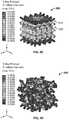
- FIG. 1Ais a variable cell of a porous material according to an embodiment of the present disclosure.
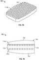
- FIG. 1Bis a lattice structure comprised of the variable cell of FIG. 1A .
- FIG. 2Aillustrates an IBD, according to an embodiment of the disclosure, under a predetermined load.
- FIG. 2Billustrates a resulting porous topology of the IBD of FIG. 2D based on a structural analysis under the predetermined load.
- FIG. 2Cis a strain map of a porous structure according to one embodiment of the present disclosure comprised of the cells of FIG. 1A .
- FIG. 2Dis a strain map of a porous structure according to another embodiment of the present disclosure.
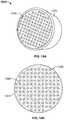
- FIG. 3Ais a top view of a vertebra illustrating a bone density of a vertebral body thereof.
- FIG. 3Bis a rear perspective view of an IBD according to an embodiment of the present disclosure.
- FIG. 3Cis a top view of the IBD of FIG. 3B .
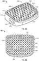
- FIG. 4Ais a front perspective view of an IBD according to another embodiment of the present disclosure.
- FIG. 4Bis a top view of the IBD of FIG. 4A .
- FIG. 4Cis side elevational view of the IBD of FIG. 4A .
- FIG. 4Dis a cross-sectional view of the IBD of FIG. 4A taken along line A-A of FIG. 4C .
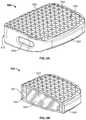
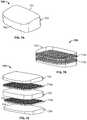
- FIG. 5Ais a front perspective view of an IBD according to a further embodiment of the present disclosure.
- FIG. 5Bis a sagittal cross-sectional perspective view of the IBD of FIG. 5A taken along a midline thereof.
- FIG. 5Cis a sagittal cross-sectional view of the IBD of FIG. 5A taken along a midline thereof.
- FIG. 6Ais a front perspective view of an IBD according to an even further embodiment of the present disclosure.
- FIG. 6Bis a top view of the IBD of FIG. 6A .
- FIG. 6Cis a sagittal cross-sectional view of the IBD of FIG. 6A taken along a midline thereof.
- FIG. 7Ais a front perspective view of an IBD according to a yet further embodiment of the present disclosure.
- FIG. 7Bis a partially transparent view of the IBD of FIG. 7A .
- FIG. 7Cis an exploded view of the IBD of FIG. 7A .
- FIG. 7Dis a transverse cross-sectional view of the IBD of FIG. 7A .
- FIG. 7Eis a sagittal cross-sectional view of the IBD of FIG. 7A .
- FIG. 8is an elevational cross-sectional view of an IBD according to a further embodiment of the present disclosure.
- FIG. 9Ais a top view of an IBD according to still another embodiment of the present disclosure.
- FIG. 9B-9Dare enhanced views of an encircled portion of the IBD of FIG. 9A depicting various configurations thereof in conjunction with a bioactive material.
- FIGS. 9E and 9Fare cross-sectional side views of separate IBD embodiments in conjunction with a bioactive material taken along a midline of the IBD's.
- FIG. 9Gis a schematic view of an IBD mold according to an embodiment of the present disclosure.
- FIG. 10Ais a top perspective view of an IBD according to a still further embodiment of the present disclosure.
- FIG. 10Bis a top view of a porous core of the IBD of FIG. 10A .
- FIG. 10Cis a sagittal cross-sectional view of the IBD of FIG. 10A .
- FIG. 10Dis an enhanced view of the porous core of the IBD of FIG. 10A .
- FIG. 11Ais a side perspective view of an IBD according to yet another embodiment of the present disclosure.
- FIG. 11Bis an enhanced view of a rear portion of the IBD of FIG. 11A .
- FIGS. 12-15are perspective views of implants according to even further embodiments of the present disclosure.
- Bonesare highly adaptive and change in response to external stimuli, such as stress. Bones typically include dense cortical bone and spongy cancellous bone. Cancellous bone has a porous structure that includes blood vessels, bone marrow, and stem cells which repair damaged or broken bone. Orthopedic implants often have porous structures which are intended to contact cancellous bone and encourage bone tissue growth therein.
- FIGS. 1A and 1Bdepict a porous structure for use in an orthopedic implant according to an embodiment of the disclosure.
- the porous structureis comprised of adjoined cells which together form a porous material volume.
- FIG. 1Adepicts a cell 100 of the porous structure.
- Such cell 100includes a plurality of intersecting members or struts 102 a - d .
- a plurality interconnected cells 100form a lattice structure.
- struts 102 a - d of cell 100 aare connected to struts of adjacent cells 100 b - d so as to form the lattice/porous structure of cells 100 .
- the struts 102 of the adjoining cells 100 a - ddefine pores or empty spaces 104 of the porous structure.
- the totality of these empty spaces 104can be expressed as the porous structure's porosity.
- the strain exhibited by a porous material of a prosthetic implant under normal operating loadscan encourage bone growth into the porous structure.
- strainis an important factor in stimulating new bone growth.
- the inventorshave found that the cells of a porous structure can be optimized by adjusting one or more geometric parameters of the cell so that the struts or members that comprise the cell exhibit a strain under operating loads that is within a target range of about 1000 to 1800 micro strain, which has been determined to be optimal for promoting bone growth without sacrificing needed strength. These parameters include the length and cross-sectional area of each individual strut that make up a cell.
- strutscan be tapered so that the cross-sectional dimension of a particular strut varies along its length.
- the overall shape or geometry of the cell, the total number of struts in a particular cell, the cross-sectional shape of the struts, the angulation of intersecting struts, the location of connection between two or more struts (i.e., the location along the length of any given strut the intersection of another strut occurs), and the likecan also be adjusted to achieve an operating strain within the desired range.
- Cell 100is illustrative of such strain optimization. More particularly, as best shown in FIG. 1A , the cross-sectional dimensions of cell 100 decrease in order from first strut 102 a to fourth strut 102 d . The differences of the cross-sectional dimensions can be used to achieve the desired strain in each strut 102 a - d based on the expected loads imposed on each strut 102 a - d .
- first strut 102 ahas the largest cross-sectional dimension as it is oriented in a direction of the largest load.
- some struts 102may have the same cross-sectional dimensions and same lengths.
- second, third, and fourth struts 102 b - deach intersect first strut 102 a such that their respective axes are obliquely angled relative to each other.
- struts 102 a - d of cell 100 aare connected to similarly sized struts 102 of adjacent cells 100 b - d .
- like struts 102can vary in size and length over porous structure 150 to ensure the resulting strain is within the target strain range.
- corresponding struts 102 of cell 100 ewhich is remote from cell 100 a , may have different lengths and/or cross-sectional dimensions.
- each strut 102 a - d in cell 100may be increased or decreased to achieve the desired porosity while the cross-sectional dimension thereof can be increased or decreased to ensure struts 102 a - d stay within the desired strain range criteria.
- the porosity of the porous structure 150may be about 10% to 90% with an average pore size of between 20-1000 microns.
- porous structure 150preferably includes a pore size of between 100 and 700 microns with a mean pore size of 400 to 500 microns and a mean porosity of 55% to 65%.
- the length of struts 102 of each cell 100 within porous structure 150may be increased or decreased to achieve the desired porosity. This allows the porosity of the porous structure to be varied throughout the porous material of an implant. Thus, a porous structure may have regions of high porosity where strut length of the porous structure's cells are longer than in regions of relatively low porosity. This also allows the porosity of the structure to gradually decrease/increase between regions of minimum and maximum porosities.
- Pore sizecan also be controlled by varying cell geometry. This may provide a discontinuous porosity change where abrupt changes in porosity may be desired.
- a porous structuremay have cells of the geometry of cell 100 and other cells of a different geometry.
- Some of the different cell geometries that can be combined with each other and cell of FIG. 1A to vary porosity and to optimize straininclude diamond cubic, single cubic, body-centered cubic, face centered cubic, tetrahedron, dodecahedron, and octahedron, to name a few. Some of these cell geometries and methods of manufacturing the same are described in the heretofore referenced '901 Patent. Varying porosities are exemplified in several of the following implant embodiments, discussed below.
- FIGS. 2A and 2BA case study, depicted in FIGS. 2A and 2B , demonstrates strain optimization using structural analysis tools.
- a sample IBD 220was constrained at an inferior side thereof and fixed in all planes to replicate the constraint of such IBD in an intervertebral space.
- a sample load of 360 Nwas applied to a superior side of IBD 220 to replicate normal operating loads within the intervertebral space.
- the target strain range for the struts of the porous structurewas set to be between 1000 and 1500 micro strains, and the target strut size was set to be between 0.4 mm and 0.8 mm.
- the resulting porous structureis depicted in FIG. 2B , which includes a variable size struts throughout the IBD 220 , which each have a strain within the predetermined range under the sample load.
- FIG. 2Cdepicts a strain map where a porous structure 200 is optimized to have a uniform strain within a target range throughout the entire volume
- FIG. 2Ddepicts a strain map in which a porous structure 200 ′ is not optimized for strain.
- Such porous structure 200 ′has a non-uniform strain throughout the entire volume and has regions of very high and very low strain.
- the porous structure 200 ′ of FIG. 2Dhas a randomized pattern of cells, such randomization would not preclude strain optimization.
- the struts of porous structure 200 ′can be adjusted in length and cross-sectional dimension so that even structure 200 ′ could exhibit a uniform strain throughout.
- an IBD, or some other prosthetic implant with a porous structuremay manufactured by designating a bone growth region or regions of the implant.
- a target/predetermined strain range between a minimum non-zero strain and a maximum non-zero strain determined to be conducive to a strain induced cellular responsemay then be selected.
- the geometry, such as length and cross-sectional dimension, of the struts of each cell in the designated bone growth region of the implant's porous structurecan then be adjusted so that each of such struts has a strain within the target range under a predetermined operating load.
- the resultant structurecan then be formed using additive manufacturing or the like.
- FIGS. 3B and 3Cdepict an IBD 300 according to an embodiment of the disclosure.
- IBD 300is particularly suitable for insertion into an intervertebral space, such as a cervical disc space, via an anterior approach.
- IBD 300generally includes a solid frame or outer wall 310 and a porous core 320 that includes a porous structure with a varying porosity.
- outer wall 310extends about porous body or core 320 and forms a perimeter thereof.
- Outer wall 310includes teeth or spikes 312 at superior and inferior sides 302 , 304 thereof.
- Such spikes 312generally extend above and below porous core 320 so that such spikes 312 can engage vertebral bodies that are disposed above and below IBD 300 to help prevent movement of IBD 300 while bone grows into porous core 320 .
- Outer wall 310also includes an engagement opening 314 at a trailing end 301 of IBD 300 .
- Such engagement opening 314is configured to connect to a corresponding inserter instrument (not shown).
- Such connectionmay be a threaded connection, collet connection, or the like.
- the solid structure of outer wall 310facilitates such a connection.
- Porous core 320is disposed within the perimeter formed by outer wall 310 and is connected to outer wall 310 such that solid outer wall 310 and porous core 320 form a unitary or monolithic device. This is preferably achieved through additive manufacturing (discussed below) in which porous core 320 and outer wall 310 are formed together layer by layer so that porous core 320 and outer wall 310 form a seamless structure. As shown, porous core 320 includes a first section or ring 322 , a second section or ring 324 , and a third section or ring 326 . In this regard, first section 322 surrounds second and third sections 324 , 326 , while second section 324 surrounds third section 326 .
- Sections 322 , 324 , and 326may be concentric.
- third section 326may be concentric with a geometric center of outer wall 310 .
- the depicted porosity gradientsneed not be concentric.
- third section 326may be biased toward leading end 303 such that third section is positioned much closer to leading end 303 than trailing end 301 .
- Sections 322 , 324 , and 326are distinguished by their relative porosities.
- porosityis generally a measure of a material's empty space relative to the total space occupied by the material.
- solid outer wall 310does not have a porosity or has a porosity of substantially zero.
- outer wall 310is considered a solid structure, it is recognized that structures that are seemingly non-porous, at least to the naked eye, may have a porosity on a very small scale. Indeed, structures that are manufactured using the additive manufacturing technique of selective laser sintering (discussed below) often have an inherent porosity to the material.
- the terms non-porous and solidmean a porosity so small or so close to zero as to prohibit bone growth therein.
- first, second, and third portions 322 , 324 , and 326 of porous core 320are distinguished by their relative porosities.
- sections 322 , 324 , and 326have differing porosities. As described above, this can be achieved by varying dimensions of cells that make up the porous structure or by varying the geometric shape of the porous structure's cells. In the particular embodiment depicted, the porosities vary so that porosity increases toward the center of core 320 .
- third section 326has a greater porosity than first and second sections 322 , 324 , and second section 324 has a greater porosity than first section 322 .
- third section 326may have a porosity of 80%
- second section 324may have a porosity of 60%
- third section 326may have a porosity of 40%.
- the first, second, and third sections 322 , 324 , and 326may have a respective porosity within the range of about 10% to 90% with an average pore width/diameter between 20-1000 microns.
- the above described arrangement of increasing porosity toward the center of IBD 100mimics the bone density of a natural vertebral body, as illustrated by the bone density map of FIG. 3A .
- the lowest density of boneis located in the center of the vertebral body with an increasing density towards the outer wall of the vertebral body.
- This correspondence to the natural bone densityhelps facilitate bone growth in that the porosity of implant 300 closely aligns with the natural porosity of the vertebral body.
- mimicking the natural bone densities of vertebrae positioned above and below IBD 300particularly where IBD is strain optimized as discussed above, reduces the overall stiffness of IBD as compared to an IBD that does not have varying porosities so as to reduce the likelihood of stress shielding.
- porous core 320can include more or less porous sections. For example, if more fidelity or precision is desired to match a particular patient's bone density, as may be determined through imaging the particular patient's bone or through matching the patient to a corresponding population within a bone database, porous core 320 can have more than three sections. For example, porous core can have 4 to 10 sections of differing porosities. Moreover, as discussed above, a gradual increase in porosity may be achieved by increasing the lengths of the struts forming the cells of the porous core so that there is almost an indiscernible number of sections of the porous core. Conversely, abrupt changes between each section can be achieved by having differing cell geometries for each section. For example, first section may be comprised of diamond cubic cells, second section may be comprised of single cubic cells, and third section may be comprised of body-centered cubic cells.
- FIGS. 4A and 4Bdepict another embodiment IBD 400 .
- IBD 400includes solid outer wall 410 and porous body or core 420 .
- porous core 420 of IBD 400also includes a first section or ring 422 , second section or ring 424 , and third section or ring 426 .
- the porosities of sections 422 , 424 , and 426mirror that of sections 322 , 324 , and 326 of IBD 300 .
- the porosity of porous core 420increases toward the center thereof such that the respective porosities of sections 422 , 424 , and 426 are within the range of about 30 to 80%.
- IBD 400also differs from IBD 300 in a number of ways.
- IBD 400is particularly suited for implantation into a lumbar disc space via an anterior approach.
- IBD 400has superior and inferior sides 402 , 404 that converge toward each other from a trailing end 401 to a leading end 403 of IBD 400 so as to provide a preferred lordotic angle.
- superior and inferior sides 402 , 404may have a slight convexity to conform to concavities in adjacent vertebral bodies.
- IBD 400includes lateral windows 418 , which may help reduce the stiffness of outer wall 410 .
- IBD 400includes spikes 412 extending from both superior and inferior sides 402 , 404 of porous core 420 .
- Such spikes 412are generally non-porous and are embedded in porous core 420 so that spikes 412 extend from upper and lower surfaces thereof.
- Spikes 412may extend partially into the respective surfaces of porous core 420 .
- spikes 412may also be constructed as columns that extend full thickness through porous core 420 .
- both IBD 300 and IBD 400include porous cores 320 , 420 that vary in porosity in a radial direction such that when these respective IBD's are implanted, each porous section of a different porosity directly contacts bone to encourage bone to grow therein.
- FIGS. 5A-5Cdepict a further IBD embodiment 500 .
- IBD 500is similar to IBD 400 in that it is particularly configured for implantation into a lumbar disc space via an anterior approach and has a lordotic taper, as best seen in FIG. 3C .
- IBD 500includes a solid outer wall 510 , porous body or core 520 , and spikes 512 embedded in inferior and superior sides 502 , 504 of porous core 520 .
- porous core 520includes a first section or outer layer 522 that entirely surrounds a second section or inner layer 524 so that when IBD 500 is implanted, only outer layer 522 of porous core 520 is exposed to adjacent vertebrae.
- Inner and outer layers 522 , 524are distinguishable based on their relative porosities where inner layer 524 preferably has a higher porosity than outer layer 522 .
- inner layer 524may have a porosity of 60%
- outer layer 522may have a porosity of 40%.
- the respective porosities of inner and outer layers 524 , 522can be within the range of about 30 to 80% with an average pore width/diameter between 20-1000 microns.
- outer layer 522may have a porosity of 10% and inner layer 524 may have a porosity of 90%.
- the lower porosity outer layer 522helps provide strength to IBD and a strong initial fusion with bone to help resist movement of IBD 500 within the disc space in response to flexion, extension, torsion, and bending range of motions.
- higher porosity inner layer 524facilitates strong long term bone ingrowth by providing more volume for bone proliferation than outer layer 522 .
- inner layer 524while potentially taking longer to facilitate bone growth, provides a stronger long term connection than outer layer 522 .
- further layerscan be provided so that the transition to the greatest porosity inner layer is more gradual.
- IBD 500may have three or four layers where each successive layer toward the center of IBD 500 has a larger porosity.
- FIGS. 6A-6Cdepict another embodiment IBD 600 , which is similar to IBD 500 .
- IBD 600includes solid outer wall 610 and porous body or core 620 where porous core 620 includes an inner layer with a larger porosity than an outer layer.
- IBD 400differs from IBD 600 in that outer layer, in addition to having a porous structure comprised of a plurality of adjoined cells, includes through-holes 618 of a much larger size than the porous structure that makes up outer layer 622 .
- outer layer 622forms a grid-like pattern in which outer layer 622 comprises intersecting beams 616 of porous material and in which spikes 412 project from outer layer 622 at the intersections of such beams 616 .
- This configurationjust as in IBD 300 , allows for a strong initial ingrowth connection between outer layer 622 and bone.
- through-holes 618facilitate enhanced blood flow to inner layer 624 over that of IBD 500 .
- through-holes 617facilitate accelerated contact between bone cells and inner layer 624 by providing a path of reduced resistance for the movement of such cells.
- further layersmay be included in IBD 600 .
- outer layer 622may not have a porous structure separate and apart from the through-openings 618 and instead may be a solid grid that is an extension of solid outer wall 610 . However, in such an embodiment, portions of inner layer 624 may extend up into through-openings 618 so as to be disposed close to the bone when implanted.
- FIGS. 7A-7Edepict a further embodiment IBD 700 .
- IBD 700is similar to the IBD's described above in that IBD 700 does not include a graft window, IBD 700 differs in that it does not include any exterior solid portions.
- IBD 700includes an entirely porous body 700 and a plurality of layers of solid reinforcing members 710 embedded in the porous body or core 720 .
- Porous body 720can be formed into any shape to suit the particular application, such as for fusion of vertebrae in the cervical or lumbar spine. The embodiment depicted is particular suited for application to a lumbar spine.
- the porosity of porous body 720may be uniform throughout or may vary as described above with respect to IBD 500 and 600 .
- the solid reinforcing members 710 a - bare gridded structures that each include a plurality of perpendicularly intersecting beams 718 that form through-openings 717 that extend in a superior-inferior direction.
- Reinforcing members 710 a - bare embedded within porous body 720 at predetermined intervals such that they each extend in respective planes that are transverse to a spinal axis when IBD 700 is implanted.
- beams 718 of reinforcing members 710 a - bextend in directions which are generally perpendicular to the compressive loads normally imposed on IBD 700 within a disc space.
- Porous body 720completely encompasses reinforcing members 710 a - b such that porous body 720 extends through through-openings 717 of reinforcing members 710 a - b , as best shown in FIG. 7D . While two reinforcing members 710 a - b are depicted, the number of reinforcing members 710 and the spacing therebetween can increase or decrease as needed to provide optimal support.
- IBD 700is a composite-like structure in which the tensile strength of solid reinforcing members 710 a - b increases the shear strength of porous body 710 , which tends to have more strength in compression than in tension.
- reinforcing members 710 a - bact in multiple directions to help alleviate stress in the areas under tension.
- reinforcing members 710 a - bcan have different configurations depending on the directions of highest tensile stress.
- reinforcing members 710 a - bcan be oriented vertically or obliquely within IBD, rather than horizontally as shown.
- reinforcing members 710 a - bmay comprise concentric rings of solid material with elongate beams extending radially from a center of the rings.
- reinforcement members 710 a - bhelp assess fusion via radiographic imagery as new bone growth is not obscured by outer solid structures and new bone growth can be measured relative to the known depth of reinforcement members 710 a - b within porous body 720 .
- windowless IBD'sare described above as having differing porous and solid structural configurations, other windowless IBD's may be modified to have similar configurations. Some of such windowless IBD's are described in U.S. Application No. 62/560,910, which is hereby incorporated by reference herein in its entirety.
- certain solid and porous configurationsare described above in association with certain types of IBD's, such as certain cervical and lumbar IBD configurations, it should be understood that the above described solid and porous configurations can be implemented in any type of spinal implant including those that can be implanted in a cervical or lumbar spine via anterior, posterior, lateral, and posterolateral approaches, for example.
- such configurationsmay be implemented in other types of orthopedic devices, such as tibial and femoral components of a knee prosthesis, femoral and acetabular components of a hip prosthesis, and humeral and glenoid components of a shoulder prosthesis, to name a few.
- such implantsoften have porous bone interfacing surfaces which, as described above, can have varying porosities to match the bone density of associated bones, or varying porosities in which an outer layer has a lower porosity to establish a strong initial connection and a higher porosity inner layer to facilitate a stronger long term connection.
- FIG. 8depicts a cross-section of another one of such windowless IBD's.
- IBD 800is similar to IBD 500 and 600 in that it includes multiple layers of a porous body or core 820 where each successive layer has a different porosity.
- IBD 800may include a solid outer wall and may also include solid projections or other bone engaging projections embedded in its porous structure, such as at superior and inferior sides 802 , 804 of IBD 800 .
- the porosity of IBD 800increases toward the inner layer 822 d of porous structure 820 .
- first layer 822 ahas the highest porosity while fourth layer 822 d has the lowest porosity.
- second layer 822 bhas a higher porosity than third layer 822 c .
- first layer 822 amay have a porosity of 70%-80%
- second layer 822 bmay have a porosity of 60%-70%
- third layer 822 cmay have a porosity of 50%-60%
- fourth layer 822 dmay have a porosity of 30%-50%.
- this change of porosity between each layer 822 a - dcan be achieved by changing the length of the struts of the cells comprising each layer 822 , and/or by changing the geometric shape of the cells that make up the layers 822 a - d .
- first layer 822 amay have cells with longer struts than second, third and fourth layers 822 b - d .
- first layer 822 amay comprise diamond cubic cells
- second layer 822 bmay comprise simple cubic cells
- third layer 822 cmay comprise body-centered cubic cells
- forth layer 822 dmay comprise face centered cubic cells, for example.
- IBD 800in which porosity decreases toward the center of IBD 800 allows a bioactive material, such as sol-gel bioactive glass (e.g., silicate, borate, and borosilicate bioglasses) or sol-gel derived bone graft, to be dispersed into the porous structure 820 of IBD 800 to enhance bone growth within the porous structure 820 .
- a bioactive materialsuch as sol-gel bioactive glass (e.g., silicate, borate, and borosilicate bioglasses) or sol-gel derived bone graft
- sol-gel bioactive glasse.g., silicate, borate, and borosilicate bioglasses
- sol-gel derived bone graftsol-gel derived bone graft
- first and second layers 822 a - bmay have an average pore size greater than the particle size of a bioactive material
- third and fourth layers 822 c - dmay have an average pore size less than the particle size of the bioactive material.
- the bioactive materialcan only be dispersed into the first and second layers 822 a - b .
- the pore size of the layers 822 a - dcan be tuned so that the bioactive material can only penetrate first layer 822 a , while in other embodiments the pore size of the layers 822 a - d can be tuned such that the bioactive material can be dispersed through all the layers 822 a - d .
- the configuration of decreasing porosity toward the center of IBD 800allows initial blood flow to penetrate into the deeper layers of IBD 800 .
- Such blood flowcan accelerate time to fusion while the internal strength of the lowest porosity layers of IBD can help resist subsidence.
- FIG. 9Adepicts another embodiment IBD 900 according to the present disclosure.
- IBD 900includes a graft window 960 .
- IBD 900includes a porous body or wall 920 or boundary surrounding graft window 960 .
- graft window 960is in communication with the pores of porous wall 920 .
- IBD 900may further include a solid outer wall surrounding porous wall 920 and bone engaging projections, like those of IBD's 400 and 500 , embedded in porous wall 920 .
- FIGS. 9B to 9Ddepict various configurations of IBD 900 in conjunction with a bioactive material, such as the bioactive materials mentioned above with respect to IBD 800 .
- a bioactive materialsuch as the bioactive materials mentioned above with respect to IBD 800 .
- FIG. 9Bdepicts a portion of porous outer wall 920 and graft window 960 .
- the bioactive material 905is selected such that the size of the beads or particles 907 are larger than the pore size of porous wall.
- the particle size of bioactive material 905may be at least 500 microns.
- the size of pores 922may be less than 500 microns, but preferably 20 to 450 microns.
- bioactive material 905may only be deposited into the graft window as the relatively large particles 907 are prohibited from being received by pores 922 .
- pores 922 of porous wall 920directly communicate with graft window 960 so that bone can proliferate from graft window 960 into the adjacent porous structure.
- bioactive material 905 ′is selected to have a particle size smaller than pores 922 of the porous structure 920 .
- the pore size of porous structure 920is 100 microns greater than the published range of the bioactive material's particle size, or 500 microns greater than its published mean particle size.
- particles 907 ′may have a particle size of 100 microns or less.
- the pore size of the porous structure 920 of implant 900may be greater than 100 microns, but preferably between 200 to 1000 microns.
- bioactive particles 907 ′penetrate the porous structure 920 so as to be dispersed therein.
- the bioactive material 905 ′fills graft window 960 . It is also contemplated, that IBD 900 may not include a graft window and instead may include the porous material in its place. In such embodiment, the bioactive material 905 ′ may be dispersed throughout such a porous structure.
- FIG. 9DThe configuration depicted in FIG. 9D is similar to that of FIG. 9C in that the particle size of the bioactive material is selected to be less than the pore size of the implant's porous structure 920 .
- graft window 960is plugged while IBD 900 is impregnated with the bioactive material, and then later unplugged so that graft window 960 does not include the bioactive material.
- the bioactive materialonly populates porous structure 920 of IBD 900 .
- Bone graft materialsuch as demineralized bone matrix or bone morphogenetic protein, can then be packed into graft window 960 , if desired.
- the IBD's described abovecan be impregnated with bioactive materials by loading the IBD into a mold, jig, or housing that substantially conforms to the IBD, such as the mold 950 depicted in FIG. 9G .
- the bioactive particlespreferably in a sol-gel state, are then injected into the mold, jig, or housing under greater than ambient pressure so as to force the bioactive material into the appropriately sized pores of the porous structure and/or the graft window of the implant.
- the solutioni.e., sol-gel
- the implantis demolded or otherwise removed from the jig or housing.
- the impregnated IBDmay then be post processed to remove an outer layer of the bioactive material so that the porous structure is exposed at the bone interfacing sides of the IBD.
- the injection molded surface of bioactive materialwhich may coat the outer surfaces of the porous structure, may not be removed so as to provide a smoother surface for implantation of the IBD.
- this processis not limited to IBD's as it can be used on any device that has a porous structure that mates with bone.
- FIG. 9Edepicts an IBD 1600 according to a further embodiment of the present disclosure.
- IBD 1600is similar to IBD 800 in that it is windowless and includes differing layers of porosity.
- outer layer 1620has a higher porosity than inner layers 1621 and 1622 .
- IBD 1600differs in that inner core has the same porosity as outer layer.
- porous channels or pathways 1612extend from outer layer 1620 to inner core 1610 such that they are in communication.
- inner layers 1621 and 1622form discrete segments of relatively lower porosity embedded in a higher porosity substrate.
- IBD 1600may be impregnated with a bioactive material such that the bioactive material is distributed through outer layer 1620 and inner core 1610 and, in some embodiments, inner layers 1621 and 1622 .
- inner layers 1621 and 1622may have a porosity that prevents the bioactive material from being distributed therein. This configuration helps control the regions in which the bioactive material can be distributed.
- IBD 1600helps enable quick bone growth for initial fixation and long-term ingrowth.
- FIG. 9Fdepicts another alternative embodiment IBD 1600 ′′, which is similar to IBD 1600 ′.
- IBD 1600 ′depicts pathways 1612 extending superiorly-inferiorly through bone contacting surfaces thereof, but also side-to-side, such as through anterior and posterior ends and/or lateral sides of IBD 1600 ′.
- IBD 1600 ′′does not include pathways extending side-to-side and instead includes a single large pathway 1612 ′ that extends superiorly-inferiorly.
- Such pathway 1612 ′extends from one bone contacting surface to another and may have the same porosity as outer layer 1620 . However, it may also have an even larger porosity than that of layer 1620 so that core 1610 ′ also has a larger porosity than outer layer 1620 .
- FIGS. 10A-10Ddepict a further embodiment IBD 1000 of the present disclosure that includes one such additional feature.
- IBD 1000is similar to the windowless IBD's above in that IBD 1000 does not have a graft window and includes a solid outer wall 1010 and porous body or core 1020 .
- IBD 1000includes a plurality of tissue through-channels 1024 that extend longitudinally through a superior side 1002 of IBD 1000 to an inferior side 1004 of IBD 1000 , as best shown in FIG. 6C .
- Through-channels 1024provide an avenue of least resistance for blood and bone cells to travel through porous structure 1022 between bones or bone fragments.
- through-channels 1024are preferably deployed in implants that fuse two or more bones or bone fragments together.
- through-channels 1024are formed in porous structure 1022 , such porous structure 1022 defines through-channels 1024 .
- blood and bone cells travelling through or residing within through-channels 1024can access the porous structure 1022 from therein, which further promotes ingrowth.
- through-channels 1024are oriented in a direction of desired bone growth.
- Through-channels 1024are elongate in that they are significantly longer than they are wide.
- Through-channels 1024are distinguishable from the porous structure 1022 surrounding such through-channels 1024 in that through-channels 1024 extend axially along their entire lengths and extend entirely through IBD 1000 .
- each of through-channels 1024have a significantly larger cross-sectional dimension than the individual pores of porous structure 1022 , as best shown in FIG. 10D .
- porous structure 1022 of porous core 1020preferably has a pore size within a range of 100 to 700 microns with a mean pore size range of about 400 to 500 microns and a mean porosity of about 55% to 65%.
- the diameter or cross-sectional dimension of any one of through-channels 1024is 0.2 to 1 mm.
- solid elongate struts or axial members 1026extend along the length of each through-channel 1024 and are positioned at a periphery thereof, as best shown in FIG. 10D .
- five axial members 1026are positioned about a central axis of each through-channel 1024 .
- more or less axial members 1026are contemplated.
- Such members 1026provide connection points for the porous structure 1022 surrounding through-channels 1024 which helps support the interface between the porous structure 1022 and channels 1024 , and also provides a surface for initial cell attachment for growth into porous structure 1022 .
- members 1026do not obscure communication between channels 1024 and the adjacent porous structure 1022 .
- longitudinal spacesare defined between adjacent axial members 1026 , as best shown in FIG. 10D , so that porous structure 1022 of core 1020 can communicate directly with channels 1024 .
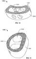
- FIGS. 11A and 11Bdepict an even further embodiment IBD 1100 , which is particularly suited for implantation into a lumbar disc space via a posterior approach.
- IBD 1100generally includes a solid outer wall 1110 and a porous body or core 1120 .
- Outer wall 1110surrounds porous core and forms a nose at a leading end 1103 .
- Outer wall 1110helps provide strength to device 1100 particular for insertion.
- a lateral window 1132extends laterally through IBD 1100 including through outer wall 1110 and porous core 1120 .
- a threaded opening 1114extends into a trailing end 1101 of IBD 1100 for connection to an inserter instrument (not shown).
- IBD 1100includes a graft window 1130 extending from a superior side to an inferior side thereof and intersects lateral graft window 1132 .
- Serrations or teeth 1112extend inwardly from solid outer wall 1110 and are embedded in porous structure 1120 , such that teeth 1112 sit proud of porous core 1120 for direct engagement with bone.
- Porous core 11120includes a porous structure similar to that of IBD 1000 in that porous core 1120 , in addition to having a plurality of pores defined by cells thereof, includes tissue through-channels 1124 extending from a superior side to an inferior side thereof. Also, tissue-channels 1124 optionally include elongate struts 1126 lining each of through-channels 1124 for support of the porous structure 1122 adjacent channels 1124 . As shown in FIG. 11A , at least one through-channel 1124 is situated between each serration. Also, through-channels 1124 are interrupted by lateral window 1132 , and are substantially smaller in cross-sectional dimension than graft window 1130 .
- graft window 1130is intended to be packed with a bone graft material
- through-channels 1124may either remain empty to facilitate tissue cell transfer or may be filled with a bioactive material.
- through channels 1124may be plugged during an injection molding process and later unplugged so that, while the porous structure 1122 of porous core 1124 may have bioactive material dispersed therein, tissue-channels 1124 remain clear of the same.
- FIGS. 12-15depict additional IBD embodiments that can deploy one or more of the optimization features described herein.
- IBD'sinclude IBD 1300 which is particular configured for implantation into a disc space via a posterior approach, IBD 1400 which is particularly configured for a posterolateral approach, IBD's 1500 and 1600 which are particularly configured for an anterior approach, and IBD 1700 which is particularly configured for a lateral approach.
- IBD's 1200 , 1300 , 1400 , and 1500similarly include solid reinforcing structures 1210 , 1310 , 1410 , and 1510 , porous structures 1220 , 1320 , 1420 , and 1520 , and graft windows 1230 , 1330 , 1430 , and 1530 such that they can be modified to include any one or more of the optimization features described herein.
- solid reinforcing structures 1210 , 1310 , 1410 , and 1510porous structures 1220 , 1320 , 1420 , and 1520
- graft windows 1230 , 1330 , 1430 , and 1530such that they can be modified to include any one or more of the optimization features described herein.
- each of these IBD'scan have one or more of a strain optimized porous structure, a porous structure with varying porosities, a porous structure and/or graft window impregnated with a bioactive material, and tissue-through channels extending from one bone interface to another bone interface, for example.
- any one of IBD's 1200 , 1300 , 1400 , and 1500while depicting graft windows, may be windowless and instead include porous material located in the spaces of windows 1230 , 1330 , 1430 , and 1530 so that such porous material can have varying porosities for facilitating bone ingrowth, as described herein.
- any of the IBD's disclosed hereincan include one or more of the optimization features described herein.
- all of these IBD'shave porous structures which can be manufactured to have varying porosities to achieve desired objectives, such as mimicking bone densities, encouraging both initial and long term connection strength, and resisting subsidence.
- the porous structures of these IBD'smay be impregnated with a bioactive material and/or may be strain optimized to have strains during operation that fall within a predetermined strain range conducive to bone growth.
- IBD's 300 , 400 , 500 , 600 , 700 , 800 , and 900may further include tissue through-channels.
- tissue through-channelsmay extend between every other bone engaging projection of IBD's 400 and 500 , and may align with the through-channels of outer layer of IBD 600 , for example.
- tissue through-channelsmay extend from superior to inferior surfaces thereof so that such channels extend through more than one, but less than all, of the openings defined in gridded reinforcement members.
- implant optimization modificationscan be used in any orthopedic application, particularly those where bone ingrowth is desirable.
- One such orthopedic applicationincludes filling bone voids in knee revision procedures using bone void filling prostheses, such as those described in U.S. Pat. No. 9,668,758, which is hereby incorporated by reference herein in its entirety.
- Such void filling prostheseshave a porous structure that can include some or all of the optimization features disclosed herein.
- the porous structure of a void filling prosthesismay have a varying porosity such that successive layers thereof have differing porosities, be impregnated with bioactive glass, and/or be strain optimized, as described above.
- hip or knee implants and the likemay include any one of the above described features.
- an intramedullary stem of an endoprosthesismay have any one of or all of a varying porosity, tissue through-channels, a porous structure impregnated with a bioactive material, and a strain optimized porous structure.
- the porous interfaces between a tibial baseplate and resected tibia, femoral component and resected distal femur, acetabular cup and resected acetabulum, and the likemay include any one of the above described features to help promote bone ingrowth and minimize stress shielding.
- the exemplary implants described herein and the features thereofmay be formed layer-by-layer using an additive layer manufacturing (ALM), i.e., 3D printing, process so no separate connection mechanism is necessary to bring together any of the components of such implants.
- ALM processesare powder-bed based and involve one or more of selective laser sintering (SLS), selective laser melting (SLM), and electron beam melting (EBM), as disclosed in the heretofore referenced '901 Patent as well as U.S. Pat. Nos. 7,537,664; 8,728,387; 9,180,010 and U.S. Patent Publication No. 2006/0147332, each of which is hereby incorporated by reference in their entireties herein.
- SLMselective laser sintering
- SLMselective laser melting
- EBMelectron beam melting
- Other methods of ALM, which can be used to form the herein described implantsinclude stereolithography (SLA), fused deposition modeling (FDM), and continuous liquid interface production (CLIP).
- articlesare produced in layer-wise fashion according to a predetermined digital model of such articles by heating, e.g., using a laser or an electron beam, multiple layers of powder, which preferably may be a metallic powder, that are dispensed one layer at a time.
- the powderis sintered in the case of SLS technology and melted in the case of SLM technology, by the application of laser energy that is directed in raster-scan fashion to portions of the powder layer corresponding to a cross section of the article.
- an additional layer of powderis dispensed, and the process repeated, with sintering or melting taking place between the current layer and the previously laid layers until the article is complete.
- the powder layerssimilarly may be heated with EBM technology.
- Additive manufacturing techniquessuch as the ALM processes described above may be employed to form the solid and porous layers and any other components, as applicable.
- materials for one layermay be different than the materials for successive layers.
- This processallows for porous portions to extend full thickness through a particular structure, such as the porous cores of the IBD's described above. It also allows porous portions to be formed in locations impossible to reach by other methods, such as adjacent through-channels 1022 and 1122 and in connection with struts 1026 and 1126 of implants 1000 and 1100 , respectively.
- itallows intricate structures to be formed, such as cell 100 and lattice structure 150 formed thereof, where traditional forms of subtractive manufacturing fall short.
- Each of solid and porous layers of the above described implantsmay be constructed from biocompatible metals, such as but not limited to any one of or any combination of titanium and its alloys, stainless steel and its alloys, magnesium and its alloys, cobalt and its alloys including a cobalt chrome alloy, nickel and its alloys, silver, tantalum, and niobium, or biocompatible polymers, such as but not limited to any one of or any combination of polyethylene (PE) and variations thereof, polyetheretherketone (PEEK), polyetherketone (PEK), acrylonitrile butadiene styrene (ABS), silicone, and cross-linked polymers.
- biocompatible metalssuch as but not limited to any one of or any combination of titanium and its alloys, stainless steel and its alloys, magnesium and its alloys, cobalt and its alloys including a cobalt chrome alloy, nickel and its alloys, silver, tantalum, and niobium
- biocompatible polymerssuch as but not limited to any one of or any combination of poly
- the implants described hereinmay be made of certain other materials such as but not limited to bioabsorbable glass, ceramics, and biological active materials including collagen/cell matrices.
- the implantmay be made of a combination of any of these metals, polymers, and other materials. All constituent porous and solid portions of the above described implants may be a common material, such as one of those listed above, or different materials can be employed for each part. Particular combinations of materials and their use for specific parts of herein described implants are a matter of design choice and may include the combination of different metals, different polymers, or metals combined with polymers.
- the solid portions of the herein described implantscan be made from a metal while the porous portions may be made from a polymer.
Landscapes
- Health & Medical Sciences (AREA)
- Engineering & Computer Science (AREA)
- Biomedical Technology (AREA)
- Orthopedic Medicine & Surgery (AREA)
- Neurology (AREA)
- Transplantation (AREA)
- Heart & Thoracic Surgery (AREA)
- Oral & Maxillofacial Surgery (AREA)
- Cardiology (AREA)
- Vascular Medicine (AREA)
- Life Sciences & Earth Sciences (AREA)
- Animal Behavior & Ethology (AREA)
- General Health & Medical Sciences (AREA)
- Public Health (AREA)
- Veterinary Medicine (AREA)
- Physical Education & Sports Medicine (AREA)
- Prostheses (AREA)
Abstract
Description
Claims (20)
Priority Applications (3)
| Application Number | Priority Date | Filing Date | Title |
|---|---|---|---|
| US16/535,524US11065126B2 (en) | 2018-08-09 | 2019-08-08 | Interbody implants and optimization features thereof |
| US17/353,988US11857430B2 (en) | 2018-08-09 | 2021-06-22 | Interbody implants and optimization features thereof |
| US18/520,060US12263091B2 (en) | 2018-08-09 | 2023-11-27 | Interbody implants and optimization features thereof |
Applications Claiming Priority (2)
| Application Number | Priority Date | Filing Date | Title |
|---|---|---|---|
| US201862716448P | 2018-08-09 | 2018-08-09 | |
| US16/535,524US11065126B2 (en) | 2018-08-09 | 2019-08-08 | Interbody implants and optimization features thereof |
Related Child Applications (1)
| Application Number | Title | Priority Date | Filing Date |
|---|---|---|---|
| US17/353,988ContinuationUS11857430B2 (en) | 2018-08-09 | 2021-06-22 | Interbody implants and optimization features thereof |
Publications (2)
| Publication Number | Publication Date |
|---|---|
| US20200046512A1 US20200046512A1 (en) | 2020-02-13 |
| US11065126B2true US11065126B2 (en) | 2021-07-20 |
Family
ID=67587591
Family Applications (4)
| Application Number | Title | Priority Date | Filing Date |
|---|---|---|---|
| US16/535,524Active2040-01-21US11065126B2 (en) | 2018-08-09 | 2019-08-08 | Interbody implants and optimization features thereof |
| US17/353,988Active2040-05-11US11857430B2 (en) | 2018-08-09 | 2021-06-22 | Interbody implants and optimization features thereof |
| US18/520,060ActiveUS12263091B2 (en) | 2018-08-09 | 2023-11-27 | Interbody implants and optimization features thereof |
| US19/064,057PendingUS20250195234A1 (en) | 2018-08-09 | 2025-02-26 | Interbody Implants and Optimization Features Thereof |
Family Applications After (3)
| Application Number | Title | Priority Date | Filing Date |
|---|---|---|---|
| US17/353,988Active2040-05-11US11857430B2 (en) | 2018-08-09 | 2021-06-22 | Interbody implants and optimization features thereof |
| US18/520,060ActiveUS12263091B2 (en) | 2018-08-09 | 2023-11-27 | Interbody implants and optimization features thereof |
| US19/064,057PendingUS20250195234A1 (en) | 2018-08-09 | 2025-02-26 | Interbody Implants and Optimization Features Thereof |
Country Status (3)
| Country | Link |
|---|---|
| US (4) | US11065126B2 (en) |
| EP (1) | EP3607914B1 (en) |
| AU (1) | AU2019213392B2 (en) |
Cited By (2)
| Publication number | Priority date | Publication date | Assignee | Title |
|---|---|---|---|---|
| US20210022882A1 (en)* | 2018-03-26 | 2021-01-28 | The Regents Of The University Of California | Medical Implants And Other Articles of Manufacture Based On Trabecular Bone Lattices |
| US20210307921A1 (en)* | 2018-08-09 | 2021-10-07 | Stryker European Operations Holdings Llc | Interbody Implants and Optimization Features Thereof |
Families Citing this family (43)
| Publication number | Priority date | Publication date | Assignee | Title |
|---|---|---|---|---|
| JP6542362B2 (en)* | 2014-09-18 | 2019-07-10 | エスアイ−ボーン・インコーポレイテッドSi−Bone, Inc. | Matrix implant |
| US11116519B2 (en) | 2017-09-26 | 2021-09-14 | Si-Bone Inc. | Systems and methods for decorticating the sacroiliac joint |
| US10183442B1 (en) | 2018-03-02 | 2019-01-22 | Additive Device, Inc. | Medical devices and methods for producing the same |
| EP3746239A2 (en) | 2018-03-05 | 2020-12-09 | Global Advanced Metals USA, Inc. | Powder metallurgy sputtering targets and methods of producing same |
| EP3746240A2 (en) | 2018-03-05 | 2020-12-09 | Global Advanced Metals USA, Inc. | Spherical tantalum powder, products containing the same, and methods of making the same |
| IL277123B2 (en) | 2018-03-05 | 2025-07-01 | Global Advanced Metals Usa Inc | Anodes containing spherical powder and capacitors |
| ES3011907T3 (en) | 2018-03-28 | 2025-04-08 | Si Bone Inc | Threaded implants for use across bone segments |
| WO2020085321A1 (en)* | 2018-10-23 | 2020-04-30 | 国立大学法人大阪大学 | Implant material and method for producing said implant material |
| EP4613244A2 (en) | 2019-02-14 | 2025-09-10 | SI-Bone Inc. | Implants for spinal fixation and or fusion |
| US11369419B2 (en) | 2019-02-14 | 2022-06-28 | Si-Bone Inc. | Implants for spinal fixation and or fusion |
| US10889053B1 (en) | 2019-03-25 | 2021-01-12 | Restor3D, Inc. | Custom surgical devices and method for manufacturing the same |
| US11051953B2 (en)* | 2019-07-31 | 2021-07-06 | Zavation Medical Products, Llc | Porous spinal implant |
| US11857436B1 (en)* | 2019-07-31 | 2024-01-02 | Zavation Medical Products, Llc | Porous spinal implant |
| US11534307B2 (en)* | 2019-09-16 | 2022-12-27 | K2M, Inc. | 3D printed cervical standalone implant |
| JP7646654B2 (en) | 2019-11-21 | 2025-03-17 | エスアイ-ボーン・インコーポレイテッド | Rod coupling assembly for bone stabilization construct - Patent application |
| AU2020392121B2 (en) | 2019-11-27 | 2025-05-22 | Si-Bone, Inc. | Bone stabilizing implants and methods of placement across SI joints |
| EP4072452A4 (en) | 2019-12-09 | 2023-12-20 | SI-Bone, Inc. | Sacro-iliac joint stabilizing implants and methods of implantation |
| USD920517S1 (en) | 2020-01-08 | 2021-05-25 | Restor3D, Inc. | Osteotomy wedge |
| US10772732B1 (en)* | 2020-01-08 | 2020-09-15 | Restor3D, Inc. | Sheet based triply periodic minimal surface implants for promoting osseointegration and methods for producing same |
| USD920516S1 (en) | 2020-01-08 | 2021-05-25 | Restor3D, Inc. | Osteotomy wedge |
| USD920515S1 (en) | 2020-01-08 | 2021-05-25 | Restor3D, Inc. | Spinal implant |
| WO2021204905A1 (en) | 2020-04-08 | 2021-10-14 | Spinewelding Ag | Bone implant |
| JP2023521775A (en)* | 2020-04-08 | 2023-05-25 | スパインウェルディング・アクチェンゲゼルシャフト | fenestrated bone anchor |
| WO2021204907A1 (en)* | 2020-04-08 | 2021-10-14 | Spinewelding Ag | Surgical system comprising an implant and a bone anchor suitable for fixating the implant relative to bone tissue |
| EP4161450B1 (en)* | 2020-06-05 | 2025-07-16 | NuVasive, Inc. | Dynamic interbody fusion devices |
| KR102422248B1 (en)* | 2020-07-10 | 2022-07-18 | 경북대학교 산학협력단 | Intervertebral Cage |
| US20230404773A1 (en)* | 2020-10-02 | 2023-12-21 | K2M, Inc. | Spinal Interbody Implants |
| US20230380983A1 (en) | 2020-10-14 | 2023-11-30 | K2M, Inc. | Spinal Interbody Implants |
| EP4259015A4 (en) | 2020-12-09 | 2024-09-11 | SI-Bone, Inc. | SACROILIAC JOINT STABILIZATION IMPLANTS AND METHODS OF IMPLANTATION |
| CN112603602B (en)* | 2020-12-30 | 2023-04-07 | 杭州电子科技大学 | A bioactive intervertebral fusion device and its manufacturing method |
| EP4574068A3 (en)* | 2020-12-30 | 2025-08-20 | Stryker European Operations Limited | A system comprising a foam structure and a surgical fixation device |
| FR3118602B1 (en)* | 2021-01-07 | 2024-04-26 | Univ De Lorraine | COMPOSITE MATERIAL WITH HOMOGENEOUS MATRIX OR GRADIENT, ITS PREPARATION PROCESS AND ITS USES |
| US11744711B2 (en)* | 2021-03-22 | 2023-09-05 | Orthofix Us Llc | Spinal interbody devices with density gradients and associated methods |
| US12167969B2 (en) | 2022-06-24 | 2024-12-17 | Nuvasive, Inc. | Resonating implant systems and methods |
| US11850144B1 (en) | 2022-09-28 | 2023-12-26 | Restor3D, Inc. | Ligament docking implants and processes for making and using same |
| US11806028B1 (en) | 2022-10-04 | 2023-11-07 | Restor3D, Inc. | Surgical guides and processes for producing and using the same |
| CN116211553A (en)* | 2023-01-05 | 2023-06-06 | 华南理工大学 | Tantalum-titanium-tantalum composite interbody fusion cage based on powder bed fusion and preparation method |
| USD1051384S1 (en) | 2023-03-24 | 2024-11-12 | Restor3D, Inc. | Bone fixation pin |
| USD1053353S1 (en) | 2023-03-24 | 2024-12-03 | Restor3D, Inc. | Orthopedic screw |
| USD1052732S1 (en) | 2023-05-25 | 2024-11-26 | Restor3D, Inc. | Subtalar wedge |
| US20250025308A1 (en)* | 2023-07-21 | 2025-01-23 | Spinal Simplicity, Llc | Porous fusion device |
| WO2025038769A1 (en) | 2023-08-15 | 2025-02-20 | Si-Bone Inc. | Pelvic stabilization implants, methods of use and manufacture |
| US11960266B1 (en) | 2023-08-23 | 2024-04-16 | Restor3D, Inc. | Patient-specific medical devices and additive manufacturing processes for producing the same |
Citations (119)
| Publication number | Priority date | Publication date | Assignee | Title |
|---|---|---|---|---|
| US896710A (en) | 1907-10-24 | 1908-08-25 | Ross D Burhans | Computer. |
| US3852045A (en) | 1972-08-14 | 1974-12-03 | Battelle Memorial Institute | Void metal composite material and method |
| US3855638A (en) | 1970-06-04 | 1974-12-24 | Ontario Research Foundation | Surgical prosthetic device with porous metal coating |
| US4612160A (en) | 1984-04-02 | 1986-09-16 | Dynamet, Inc. | Porous metal coating process and mold therefor |
| US4863538A (en) | 1986-10-17 | 1989-09-05 | Board Of Regents, The University Of Texas System | Method and apparatus for producing parts by selective sintering |
| US4944817A (en) | 1986-10-17 | 1990-07-31 | Board Of Regents, The University Of Texas System | Multiple material systems for selective beam sintering |
| US5017753A (en) | 1986-10-17 | 1991-05-21 | Board Of Regents, The University Of Texas System | Method and apparatus for producing parts by selective sintering |
| US5071437A (en) | 1989-02-15 | 1991-12-10 | Acromed Corporation | Artificial disc |
| US5076869A (en) | 1986-10-17 | 1991-12-31 | Board Of Regents, The University Of Texas System | Multiple material systems for selective beam sintering |
| EP0505634A1 (en) | 1991-03-29 | 1992-09-30 | Kyocera Corporation | A prosthesis |
| US5263986A (en) | 1992-02-19 | 1993-11-23 | Joint Medical Products Corporation | Sintered coatings for implantable prostheses |
| US5370692A (en) | 1992-08-14 | 1994-12-06 | Guild Associates, Inc. | Rapid, customized bone prosthesis |
| US5504300A (en) | 1994-04-18 | 1996-04-02 | Zimmer, Inc. | Orthopaedic implant and method of making same |
| US5507815A (en) | 1991-06-17 | 1996-04-16 | Cycam, Inc. | Random surface protrusions on an implantable device |
| US5734959A (en) | 1995-10-12 | 1998-03-31 | Zimmer, Inc. | Method of making an orthopaedic implant having a porous surface using an organic binder |
| US5768134A (en) | 1994-04-19 | 1998-06-16 | Materialise, Naamloze Vennootschap | Method for making a perfected medical model on the basis of digital image information of a part of the body |
| WO1999020208A1 (en) | 1997-10-17 | 1999-04-29 | Sbm Societe Anonyme | Implant for interbody fusion of the spine and the like |
| US5961554A (en) | 1996-12-31 | 1999-10-05 | Janson; Frank S | Intervertebral spacer |
| US6149688A (en) | 1995-06-07 | 2000-11-21 | Surgical Dynamics, Inc. | Artificial bone graft implant |
| US6471725B1 (en) | 2001-07-16 | 2002-10-29 | Third Millenium Engineering, Llc | Porous intervertebral distraction spacers |
| US6485521B1 (en) | 1999-12-08 | 2002-11-26 | Wen-Ching Say | Orthopedic implant having a porous surface and method of making same |
| US6533818B1 (en) | 2000-04-26 | 2003-03-18 | Pearl Technology Holdings, Llc | Artificial spinal disc |
| US20030055505A1 (en) | 2001-09-04 | 2003-03-20 | Benoit Sicotte | Intervertebral fusion device |
| US6569201B2 (en) | 2001-09-28 | 2003-05-27 | Depuy Acromed, Inc. | Hybrid composite interbody fusion device |
| US6572654B1 (en) | 2000-10-04 | 2003-06-03 | Albert N. Santilli | Intervertebral spacer |
| US6673075B2 (en) | 2001-02-23 | 2004-01-06 | Albert N. Santilli | Porous intervertebral spacer |
| US6740186B2 (en) | 2002-02-20 | 2004-05-25 | Zimmer Technology, Inc. | Method of making an orthopeadic implant having a porous metal surface |
| US20040133279A1 (en) | 2003-01-06 | 2004-07-08 | Krueger David J. | Surgical implants for use as spinal spacers |
| US6790233B2 (en) | 2001-05-01 | 2004-09-14 | Amedica Corporation | Radiolucent spinal fusion cage |
| US6863689B2 (en) | 2001-07-16 | 2005-03-08 | Spinecore, Inc. | Intervertebral spacer having a flexible wire mesh vertebral body contact element |
| US20050123672A1 (en) | 2003-12-03 | 2005-06-09 | Justin Daniel F. | Laser based metal deposition of implant structures |
| US20050177238A1 (en) | 2001-05-01 | 2005-08-11 | Khandkar Ashok C. | Radiolucent bone graft |
| US20050203630A1 (en) | 2000-01-30 | 2005-09-15 | Pope Bill J. | Prosthetic knee joint having at least one diamond articulation surface |
| US7135042B2 (en) | 2002-03-30 | 2006-11-14 | Hfsc Company | Surgical implant |
| WO2006121795A2 (en) | 2005-05-06 | 2006-11-16 | Titan Spine, Llc | Anterior interbody spinal implant |
| US7238203B2 (en) | 2001-12-12 | 2007-07-03 | Vita Special Purpose Corporation | Bioactive spinal implants and method of manufacture thereof |
| US7241313B2 (en) | 2001-08-11 | 2007-07-10 | Stanmore Implants Worldwide Limited | Surgical implant |
| US20070218098A1 (en) | 2003-06-26 | 2007-09-20 | Dieter Reif | Bone Formation Agent And Method Of Production |
| US20080161927A1 (en) | 2006-10-18 | 2008-07-03 | Warsaw Orthopedic, Inc. | Intervertebral Implant with Porous Portions |
| US20080183292A1 (en) | 2007-01-29 | 2008-07-31 | Warsaw Orthopedic, Inc. | Compliant intervertebral prosthetic devices employing composite elastic and textile structures |
| EP1961433A1 (en) | 2007-02-20 | 2008-08-27 | National University of Ireland Galway | Porous substrates for implantation |
| US20080306595A1 (en) | 2004-03-26 | 2008-12-11 | Pearsalls Limited | Porous Implant For Spinal Disc Nucleus Replacement |
| US7497876B2 (en) | 2003-11-03 | 2009-03-03 | Finsbury (Development) Limited | Prosthetic implant |
| US20090093885A1 (en) | 2005-12-20 | 2009-04-09 | Spineart S.A. | Anatomic intervertebral spacer and the applications thereof |
| US20090222098A1 (en)* | 2008-02-28 | 2009-09-03 | Warsaw Orthopedics, Inc. | Spinal nucleus replacement with varying modulus |
| US7635447B2 (en) | 2006-02-17 | 2009-12-22 | Biomet Manufacturing Corp. | Method and apparatus for forming porous metal implants |
| US20100042218A1 (en) | 2008-08-13 | 2010-02-18 | Nebosky Paul S | Orthopaedic implant with porous structural member |
| US20100076559A1 (en) | 2007-05-04 | 2010-03-25 | Titan Spine, Llc | Composite telescoping anterior interbody spinal implant |
| US20100094426A1 (en) | 2008-10-14 | 2010-04-15 | Grohowski Jr Joseph A | Hybrid intervertebral spinal implant |
| US20100256773A1 (en) | 2007-07-03 | 2010-10-07 | Vlaamse Instelling Voor Technologisch Onderzoek N.V. (Vito) | Surgical implant composed of a porous core and a dense surface layer |
| US20100262244A1 (en) | 2009-04-14 | 2010-10-14 | Warsaw Orthopedic, Inc. | Metal Coated Implant |
| US20110015743A1 (en)* | 2009-07-14 | 2011-01-20 | Doctors Research Group, Inc. | Multi-density polymeric interbody spacer |
| US20110012280A1 (en) | 2009-07-14 | 2011-01-20 | Doctors Research Group, Inc. | Method for fabricating a multi-density polymeric interbody spacer |
| US20110071635A1 (en)* | 2009-09-23 | 2011-03-24 | Zimmer Spine, Inc. | Composite implant |
| US7922765B2 (en) | 2004-08-09 | 2011-04-12 | Si-Bone, Inc. | Systems and methods for the fixation or fusion of bone |
| US20110282392A1 (en) | 2006-10-30 | 2011-11-17 | Tissue Regeneration Systems, Inc. | Degradable cage for bone fusion |
| US20110285454A1 (en) | 2010-05-21 | 2011-11-24 | Tpk Touch Solutions (Xiamen) Inc. | Inductive touch sensor and detecting method |
| US20110313538A1 (en)* | 2007-08-09 | 2011-12-22 | The Board Of Regents Of The University Of Texas System | Bi-layered bone-like scaffolds |
| CN102293693A (en) | 2011-06-01 | 2011-12-28 | 中国人民解放军第四军医大学 | Porous titanium alloy human cervical interbody fusion cage with bioactivity and preparation method thereof |
| US8147861B2 (en) | 2006-08-15 | 2012-04-03 | Howmedica Osteonics Corp. | Antimicrobial implant |
| US20120150299A1 (en)* | 2010-06-10 | 2012-06-14 | Ergun Asli | Integrated multi-zonal cage/core implants as bone graft substitutes and apparatus and method for their fabrication |
| US8262737B2 (en) | 2005-05-06 | 2012-09-11 | Titan Spine, Llc | Composite interbody spinal implant having openings of predetermined size and shape |
| US8266780B2 (en) | 2005-04-21 | 2012-09-18 | Biomet Manufacturing Corp. | Method and apparatus for use of porous implants |
| US8268100B2 (en) | 2002-11-08 | 2012-09-18 | Howmedica Osteonics Corp. | Laser-produced porous surface |
| US20120265306A1 (en) | 2011-04-14 | 2012-10-18 | Warsaw Orthopedic, Inc. | Spinal implant with attachable bone securing componet |
| US8303879B2 (en) | 2010-02-01 | 2012-11-06 | Sb Technologies, Llc | Composite interbody device and method of manufacture |
| US20120303127A1 (en) | 2005-05-06 | 2012-11-29 | Titan Spine, Llc | Implants having internal features for graft retention and load transfer between implant and vertebrae |
| US20120312778A1 (en) | 2005-05-06 | 2012-12-13 | Titan Spine, Llc | Processes for producing regular repeating patterns on surfaces of interbody devices |
| US20120312779A1 (en) | 2005-05-06 | 2012-12-13 | Titian Spine, LLC | Methods for manufacturing implants having integration surfaces |
| US20120330420A1 (en) | 2001-05-01 | 2012-12-27 | Amedica Corporation | Spinal fusion implants |
| US8403991B2 (en) | 2005-05-06 | 2013-03-26 | Titan Spine Llc | Implant with critical ratio of load bearing surface area to central opening area |
| US8414654B1 (en) | 2011-11-23 | 2013-04-09 | Amendia, Inc. | Bone implants and method of manufacture |
| US8425604B2 (en) | 2011-01-20 | 2013-04-23 | Warsaw Orthopedic, Inc. | Spinal implant with attachable bone securing component |
| US8435302B2 (en) | 2005-05-06 | 2013-05-07 | Titan Spine, Llc | Instruments and interbody spinal implants enhancing disc space distraction |
| US20130116793A1 (en)* | 2010-07-23 | 2013-05-09 | Privelop-Spine Ag | Surgical implant |
| US8480749B2 (en) | 2005-05-06 | 2013-07-09 | Titan Spine, Llc | Friction fit and vertebral endplate-preserving spinal implant |
| US8530560B2 (en) | 2008-02-01 | 2013-09-10 | DePuy Synthes Products, LLC | Porous biocompatible polymer material and methods |
| US8532806B1 (en) | 2010-06-07 | 2013-09-10 | Marcos V. Masson | Process for manufacture of joint implants |
| US8545568B2 (en) | 2005-05-06 | 2013-10-01 | Titan Spine, Llc | Method of using instruments and interbody spinal implants to enhance distraction |
| US8545572B2 (en) | 2011-01-21 | 2013-10-01 | Trilliant Surgical, Ltd. | Subtalar implant |
| US8551176B2 (en) | 2005-05-06 | 2013-10-08 | Titan Spine, Llc | Spinal implant having a passage for enhancing contact between bone graft material and cortical endplate bone |
| US8551173B2 (en) | 2008-01-17 | 2013-10-08 | DePuy Synthes Products, LLC | Expandable intervertebral implant and associated method of manufacturing the same |
| US8556981B2 (en) | 2005-12-06 | 2013-10-15 | Howmedica Osteonics Corp. | Laser-produced porous surface |
| US20130274886A1 (en) | 2010-11-10 | 2013-10-17 | Mitsubishi Materials Corporation | Vertebral body spacer |
| US8562684B2 (en) | 2005-05-06 | 2013-10-22 | Titan Spine, Llc | Endplate-preserving spinal implant with an integration plate having a roughened surface topography |
| US20130282122A1 (en) | 2005-05-06 | 2013-10-24 | Titan Spine, Llc | Interbody spinal implant having a roughened surface topography on one or more internal surfaces |
| US8585767B2 (en) | 2005-05-06 | 2013-11-19 | Titan Spine, Llc | Endplate-preserving spinal implant with an integration plate having durable connectors |
| US20130325129A1 (en)* | 2012-05-30 | 2013-12-05 | Ossaware Biotech Co., Ltd. | Textured implant device |
| US8617248B2 (en) | 2005-05-06 | 2013-12-31 | Titan Spine, Llc | Spinal implant having variable ratios of the integration surface area to the axial passage area |
| US8632604B2 (en) | 2009-10-22 | 2014-01-21 | Depuy International Limited | Medical implant device |
| US20140107786A1 (en)* | 2012-10-11 | 2014-04-17 | Rhausler, Inc. | Fusion cage implant with lattice structure |
| US20140114415A1 (en) | 2012-10-19 | 2014-04-24 | Jeffrey Tyber | Orthopedic Systems for Spine and Tracking Control |
| US20140121776A1 (en) | 2012-09-25 | 2014-05-01 | 4Web, Inc. | Programmable implants and methods of using programmable implants to repair bone structures |
| US8735773B2 (en) | 2007-02-14 | 2014-05-27 | Conformis, Inc. | Implant device and method for manufacture |
| US20140264995A1 (en)* | 2013-03-15 | 2014-09-18 | Amedica Corporation | Thin-walled implant structures and related methods |
| US20140277461A1 (en)* | 2013-03-15 | 2014-09-18 | Smed-Ta/Td, Llc | Porous tissue ingrowth structure |
| US20140277491A1 (en)* | 2013-03-15 | 2014-09-18 | Blackstone Medical, Inc. | Composite spinal interbody device and method |
| US20150018956A1 (en) | 2012-06-21 | 2015-01-15 | Renovis Surgical, Inc. | Surgical implant devices incorporating porous surfaces |
| WO2015017324A1 (en) | 2013-08-02 | 2015-02-05 | Bi02 Technologies, Inc. | Resorbable interbody device |
| US20150045903A1 (en)* | 2013-08-09 | 2015-02-12 | David J. Neal | Orthopedic implants and methods of manufacturing orthopedic implants |
| US8979934B2 (en) | 2010-07-20 | 2015-03-17 | X-Spine Systems, Inc. | Composite orthopedic implant having a low friction material substrate with primary frictional features and secondary frictional features |
| US8992619B2 (en) | 2011-11-01 | 2015-03-31 | Titan Spine, Llc | Microstructured implant surfaces |
| US20150134063A1 (en) | 2012-06-21 | 2015-05-14 | Renovis Surgical Technologies, Inc. | Surgical implant devices incorporating porous surfaces and a locking plate |
| US9243278B2 (en) | 2011-09-22 | 2016-01-26 | Brown University | Mechanotransduction by the synergistic action of heterotypic cell interactions |
| US20160157908A1 (en) | 2014-07-24 | 2016-06-09 | Renovis Surgical Technologies, Inc. | Bone screw incorporating a porous surface formed by an additive manufacturing process |
| US9415137B2 (en) | 2012-08-22 | 2016-08-16 | Biomet Manufacturing, Llc. | Directional porous coating |
| US20160270920A1 (en)* | 2014-10-23 | 2016-09-22 | Spinesmith Partners, L.P. | Treatment of skeletal voids with implantable substrate hydrated with bone marrow concentrate |
| US9456901B2 (en) | 2004-12-30 | 2016-10-04 | Howmedica Osteonics Corp. | Laser-produced porous structure |
| US20170020685A1 (en)* | 2012-10-11 | 2017-01-26 | Rhausler, Inc. | Fusion cage implant with lattice structure and grooves |
| US20170056190A1 (en) | 2015-08-27 | 2017-03-02 | Wright Medical Technology, Inc. | Subtalar biofoam wedge |
| US20170095337A1 (en) | 2014-05-02 | 2017-04-06 | The Royal Institution For The Advancement Of Learning/Mcgill University | Structural porous biomaterial and implant formed of same |
| US20170156878A1 (en)* | 2015-12-07 | 2017-06-08 | Industrial Technology Research Institute | Implant device for osseous integration |
| WO2017106780A1 (en) | 2015-12-16 | 2017-06-22 | Nuvasive, Inc. | Porous spinal fusion implant |
| US9700431B2 (en)* | 2008-08-13 | 2017-07-11 | Smed-Ta/Td, Llc | Orthopaedic implant with porous structural member |
| US9848995B2 (en) | 2012-03-20 | 2017-12-26 | Titan Spine Llc | Process for fabricating bioactive vertebral endplate bone-contacting surfaces on a spinal implant |
| US10512545B2 (en)* | 2016-10-24 | 2019-12-24 | Corelink, Llc | Interbody spacer for spinal fusion |
| US20200046512A1 (en)* | 2018-08-09 | 2020-02-13 | Stryker European Operations Holdings, LLC | Interbody Implants and Optimization Features Thereof |
| US10792129B2 (en)* | 2015-02-03 | 2020-10-06 | University Of Maine System Board Of Trustees | Soft tissue in-growth of porous, three-dimensionally printed, transcutaneous implants of varying material and pore geometry |
| US10835388B2 (en)* | 2017-09-20 | 2020-11-17 | Stryker European Operations Holdings Llc | Spinal implants |
Family Cites Families (9)
| Publication number | Priority date | Publication date | Assignee | Title |
|---|---|---|---|---|
| US7470273B2 (en)* | 2004-06-25 | 2008-12-30 | Ebi, Llc | Tool for intervertebral implant manipulation |
| US8641764B2 (en)* | 2006-10-11 | 2014-02-04 | G&L Consulting, Llc | Spine implant insertion device and method |
| US8858637B2 (en)* | 2010-09-30 | 2014-10-14 | Stryker Spine | Surgical implant with guiding rail |
| US9180010B2 (en) | 2012-04-06 | 2015-11-10 | Howmedica Osteonics Corp. | Surface modified unit cell lattice structures for optimized secure freeform fabrication |
| US9135374B2 (en) | 2012-04-06 | 2015-09-15 | Howmedica Osteonics Corp. | Surface modified unit cell lattice structures for optimized secure freeform fabrication |
| US9526513B2 (en) | 2013-03-13 | 2016-12-27 | Howmedica Osteonics Corp. | Void filling joint prosthesis and associated instruments |
| AU2016200179B2 (en) | 2015-01-14 | 2020-09-17 | Stryker European Operations Holdings Llc | Spinal implant with porous and solid surfaces |
| WO2017005514A1 (en)* | 2015-07-09 | 2017-01-12 | Waldemar Link Gmbh & Co. Kg | Porous structure for bone implants |
| US11039933B2 (en)* | 2017-12-15 | 2021-06-22 | Innovasis, Inc. | Interbody spinal fusion implant with support struts |
- 2019
- 2019-08-08USUS16/535,524patent/US11065126B2/enactiveActive
- 2019-08-08AUAU2019213392Apatent/AU2019213392B2/enactiveActive
- 2019-08-09EPEP19190934.0Apatent/EP3607914B1/enactiveActive
- 2021
- 2021-06-22USUS17/353,988patent/US11857430B2/enactiveActive
- 2023
- 2023-11-27USUS18/520,060patent/US12263091B2/enactiveActive
- 2025
- 2025-02-26USUS19/064,057patent/US20250195234A1/enactivePending
Patent Citations (132)
| Publication number | Priority date | Publication date | Assignee | Title |
|---|---|---|---|---|
| US896710A (en) | 1907-10-24 | 1908-08-25 | Ross D Burhans | Computer. |
| US3855638A (en) | 1970-06-04 | 1974-12-24 | Ontario Research Foundation | Surgical prosthetic device with porous metal coating |
| US3852045A (en) | 1972-08-14 | 1974-12-03 | Battelle Memorial Institute | Void metal composite material and method |
| US4612160A (en) | 1984-04-02 | 1986-09-16 | Dynamet, Inc. | Porous metal coating process and mold therefor |
| US5076869A (en) | 1986-10-17 | 1991-12-31 | Board Of Regents, The University Of Texas System | Multiple material systems for selective beam sintering |
| US4863538A (en) | 1986-10-17 | 1989-09-05 | Board Of Regents, The University Of Texas System | Method and apparatus for producing parts by selective sintering |
| US4944817A (en) | 1986-10-17 | 1990-07-31 | Board Of Regents, The University Of Texas System | Multiple material systems for selective beam sintering |
| US5017753A (en) | 1986-10-17 | 1991-05-21 | Board Of Regents, The University Of Texas System | Method and apparatus for producing parts by selective sintering |
| US5071437A (en) | 1989-02-15 | 1991-12-10 | Acromed Corporation | Artificial disc |
| US5458643A (en) | 1991-03-29 | 1995-10-17 | Kyocera Corporation | Artificial intervertebral disc |
| EP0505634A1 (en) | 1991-03-29 | 1992-09-30 | Kyocera Corporation | A prosthesis |
| US5507815A (en) | 1991-06-17 | 1996-04-16 | Cycam, Inc. | Random surface protrusions on an implantable device |
| US6911249B2 (en) | 1991-06-17 | 2005-06-28 | Medsource Technologies Pittsburgh, Inc. | Surface for use on implantable device |
| US5263986A (en) | 1992-02-19 | 1993-11-23 | Joint Medical Products Corporation | Sintered coatings for implantable prostheses |
| US5370692A (en) | 1992-08-14 | 1994-12-06 | Guild Associates, Inc. | Rapid, customized bone prosthesis |
| US5504300A (en) | 1994-04-18 | 1996-04-02 | Zimmer, Inc. | Orthopaedic implant and method of making same |
| US5672284A (en) | 1994-04-18 | 1997-09-30 | Zimmer, Inc. | Method of making orthopaedic implant by welding |
| US5768134A (en) | 1994-04-19 | 1998-06-16 | Materialise, Naamloze Vennootschap | Method for making a perfected medical model on the basis of digital image information of a part of the body |
| US6149688A (en) | 1995-06-07 | 2000-11-21 | Surgical Dynamics, Inc. | Artificial bone graft implant |
| US5734959A (en) | 1995-10-12 | 1998-03-31 | Zimmer, Inc. | Method of making an orthopaedic implant having a porous surface using an organic binder |
| US5961554A (en) | 1996-12-31 | 1999-10-05 | Janson; Frank S | Intervertebral spacer |
| WO1999020208A1 (en) | 1997-10-17 | 1999-04-29 | Sbm Societe Anonyme | Implant for interbody fusion of the spine and the like |
| US6485521B1 (en) | 1999-12-08 | 2002-11-26 | Wen-Ching Say | Orthopedic implant having a porous surface and method of making same |
| US20050203630A1 (en) | 2000-01-30 | 2005-09-15 | Pope Bill J. | Prosthetic knee joint having at least one diamond articulation surface |
| US6533818B1 (en) | 2000-04-26 | 2003-03-18 | Pearl Technology Holdings, Llc | Artificial spinal disc |
| US6572654B1 (en) | 2000-10-04 | 2003-06-03 | Albert N. Santilli | Intervertebral spacer |
| US6673075B2 (en) | 2001-02-23 | 2004-01-06 | Albert N. Santilli | Porous intervertebral spacer |
| US6790233B2 (en) | 2001-05-01 | 2004-09-14 | Amedica Corporation | Radiolucent spinal fusion cage |
| US20120330420A1 (en) | 2001-05-01 | 2012-12-27 | Amedica Corporation | Spinal fusion implants |
| US20050177238A1 (en) | 2001-05-01 | 2005-08-11 | Khandkar Ashok C. | Radiolucent bone graft |
| US6863689B2 (en) | 2001-07-16 | 2005-03-08 | Spinecore, Inc. | Intervertebral spacer having a flexible wire mesh vertebral body contact element |
| US6623525B2 (en) | 2001-07-16 | 2003-09-23 | Spinecore, Inc. | Porous intervertebral distraction spacers |
| US6471725B1 (en) | 2001-07-16 | 2002-10-29 | Third Millenium Engineering, Llc | Porous intervertebral distraction spacers |
| US8361153B2 (en) | 2001-07-16 | 2013-01-29 | Spinecore, Inc. | Porous intervertebral distraction spacers |
| US7241313B2 (en) | 2001-08-11 | 2007-07-10 | Stanmore Implants Worldwide Limited | Surgical implant |
| US20030055505A1 (en) | 2001-09-04 | 2003-03-20 | Benoit Sicotte | Intervertebral fusion device |
| US6569201B2 (en) | 2001-09-28 | 2003-05-27 | Depuy Acromed, Inc. | Hybrid composite interbody fusion device |
| US7238203B2 (en) | 2001-12-12 | 2007-07-03 | Vita Special Purpose Corporation | Bioactive spinal implants and method of manufacture thereof |
| US6740186B2 (en) | 2002-02-20 | 2004-05-25 | Zimmer Technology, Inc. | Method of making an orthopeadic implant having a porous metal surface |
| US7135042B2 (en) | 2002-03-30 | 2006-11-14 | Hfsc Company | Surgical implant |
| US8268100B2 (en) | 2002-11-08 | 2012-09-18 | Howmedica Osteonics Corp. | Laser-produced porous surface |
| US20040133279A1 (en) | 2003-01-06 | 2004-07-08 | Krueger David J. | Surgical implants for use as spinal spacers |
| US20070218098A1 (en) | 2003-06-26 | 2007-09-20 | Dieter Reif | Bone Formation Agent And Method Of Production |
| US7497876B2 (en) | 2003-11-03 | 2009-03-03 | Finsbury (Development) Limited | Prosthetic implant |
| US20050123672A1 (en) | 2003-12-03 | 2005-06-09 | Justin Daniel F. | Laser based metal deposition of implant structures |
| US20080306595A1 (en) | 2004-03-26 | 2008-12-11 | Pearsalls Limited | Porous Implant For Spinal Disc Nucleus Replacement |
| US7922765B2 (en) | 2004-08-09 | 2011-04-12 | Si-Bone, Inc. | Systems and methods for the fixation or fusion of bone |
| US9456901B2 (en) | 2004-12-30 | 2016-10-04 | Howmedica Osteonics Corp. | Laser-produced porous structure |
| US8266780B2 (en) | 2005-04-21 | 2012-09-18 | Biomet Manufacturing Corp. | Method and apparatus for use of porous implants |
| US8617248B2 (en) | 2005-05-06 | 2013-12-31 | Titan Spine, Llc | Spinal implant having variable ratios of the integration surface area to the axial passage area |
| US20130282122A1 (en) | 2005-05-06 | 2013-10-24 | Titan Spine, Llc | Interbody spinal implant having a roughened surface topography on one or more internal surfaces |
| US8562684B2 (en) | 2005-05-06 | 2013-10-22 | Titan Spine, Llc | Endplate-preserving spinal implant with an integration plate having a roughened surface topography |
| US7662186B2 (en) | 2005-05-06 | 2010-02-16 | Titan Spine, Llc | Anterior interbody spinal implant |
| US8551176B2 (en) | 2005-05-06 | 2013-10-08 | Titan Spine, Llc | Spinal implant having a passage for enhancing contact between bone graft material and cortical endplate bone |
| US8545568B2 (en) | 2005-05-06 | 2013-10-01 | Titan Spine, Llc | Method of using instruments and interbody spinal implants to enhance distraction |
| US8480749B2 (en) | 2005-05-06 | 2013-07-09 | Titan Spine, Llc | Friction fit and vertebral endplate-preserving spinal implant |
| US8435302B2 (en) | 2005-05-06 | 2013-05-07 | Titan Spine, Llc | Instruments and interbody spinal implants enhancing disc space distraction |
| US8403991B2 (en) | 2005-05-06 | 2013-03-26 | Titan Spine Llc | Implant with critical ratio of load bearing surface area to central opening area |
| WO2006121795A2 (en) | 2005-05-06 | 2006-11-16 | Titan Spine, Llc | Anterior interbody spinal implant |
| US8262737B2 (en) | 2005-05-06 | 2012-09-11 | Titan Spine, Llc | Composite interbody spinal implant having openings of predetermined size and shape |
| US8585767B2 (en) | 2005-05-06 | 2013-11-19 | Titan Spine, Llc | Endplate-preserving spinal implant with an integration plate having durable connectors |
| US20120312779A1 (en) | 2005-05-06 | 2012-12-13 | Titian Spine, LLC | Methods for manufacturing implants having integration surfaces |
| US20120312778A1 (en) | 2005-05-06 | 2012-12-13 | Titan Spine, Llc | Processes for producing regular repeating patterns on surfaces of interbody devices |
| US20120303127A1 (en) | 2005-05-06 | 2012-11-29 | Titan Spine, Llc | Implants having internal features for graft retention and load transfer between implant and vertebrae |
| US8556981B2 (en) | 2005-12-06 | 2013-10-15 | Howmedica Osteonics Corp. | Laser-produced porous surface |
| US20090093885A1 (en) | 2005-12-20 | 2009-04-09 | Spineart S.A. | Anatomic intervertebral spacer and the applications thereof |
| US7635447B2 (en) | 2006-02-17 | 2009-12-22 | Biomet Manufacturing Corp. | Method and apparatus for forming porous metal implants |
| US8147861B2 (en) | 2006-08-15 | 2012-04-03 | Howmedica Osteonics Corp. | Antimicrobial implant |
| US20080161927A1 (en) | 2006-10-18 | 2008-07-03 | Warsaw Orthopedic, Inc. | Intervertebral Implant with Porous Portions |
| US20110282392A1 (en) | 2006-10-30 | 2011-11-17 | Tissue Regeneration Systems, Inc. | Degradable cage for bone fusion |
| US20080183292A1 (en) | 2007-01-29 | 2008-07-31 | Warsaw Orthopedic, Inc. | Compliant intervertebral prosthetic devices employing composite elastic and textile structures |
| US8735773B2 (en) | 2007-02-14 | 2014-05-27 | Conformis, Inc. | Implant device and method for manufacture |
| EP1961433A1 (en) | 2007-02-20 | 2008-08-27 | National University of Ireland Galway | Porous substrates for implantation |
| US20100137990A1 (en) | 2007-02-20 | 2010-06-03 | National University Of Ireland, Galway | Porous Substrates for Implantation |
| US20100076559A1 (en) | 2007-05-04 | 2010-03-25 | Titan Spine, Llc | Composite telescoping anterior interbody spinal implant |
| US20100256773A1 (en) | 2007-07-03 | 2010-10-07 | Vlaamse Instelling Voor Technologisch Onderzoek N.V. (Vito) | Surgical implant composed of a porous core and a dense surface layer |
| US20110313538A1 (en)* | 2007-08-09 | 2011-12-22 | The Board Of Regents Of The University Of Texas System | Bi-layered bone-like scaffolds |
| US20170165085A1 (en) | 2008-01-17 | 2017-06-15 | DePuy Synthes Products, Inc. | Expandable intervertebral implant and associated method of manufacturing the same |
| US8551173B2 (en) | 2008-01-17 | 2013-10-08 | DePuy Synthes Products, LLC | Expandable intervertebral implant and associated method of manufacturing the same |
| US20140207237A1 (en) | 2008-02-01 | 2014-07-24 | DePuy Synthes Products, LLC | Porous Biocompatible Polymer Material and Methods |
| US8530560B2 (en) | 2008-02-01 | 2013-09-10 | DePuy Synthes Products, LLC | Porous biocompatible polymer material and methods |
| US20090222098A1 (en)* | 2008-02-28 | 2009-09-03 | Warsaw Orthopedics, Inc. | Spinal nucleus replacement with varying modulus |
| US9700431B2 (en)* | 2008-08-13 | 2017-07-11 | Smed-Ta/Td, Llc | Orthopaedic implant with porous structural member |
| US20100042218A1 (en) | 2008-08-13 | 2010-02-18 | Nebosky Paul S | Orthopaedic implant with porous structural member |
| US20100094426A1 (en) | 2008-10-14 | 2010-04-15 | Grohowski Jr Joseph A | Hybrid intervertebral spinal implant |
| US20100262244A1 (en) | 2009-04-14 | 2010-10-14 | Warsaw Orthopedic, Inc. | Metal Coated Implant |
| US20110015743A1 (en)* | 2009-07-14 | 2011-01-20 | Doctors Research Group, Inc. | Multi-density polymeric interbody spacer |
| US20110012280A1 (en) | 2009-07-14 | 2011-01-20 | Doctors Research Group, Inc. | Method for fabricating a multi-density polymeric interbody spacer |
| US20110071635A1 (en)* | 2009-09-23 | 2011-03-24 | Zimmer Spine, Inc. | Composite implant |
| US8632604B2 (en) | 2009-10-22 | 2014-01-21 | Depuy International Limited | Medical implant device |
| US8303879B2 (en) | 2010-02-01 | 2012-11-06 | Sb Technologies, Llc | Composite interbody device and method of manufacture |
| US20110285454A1 (en) | 2010-05-21 | 2011-11-24 | Tpk Touch Solutions (Xiamen) Inc. | Inductive touch sensor and detecting method |
| US8532806B1 (en) | 2010-06-07 | 2013-09-10 | Marcos V. Masson | Process for manufacture of joint implants |
| US20120150299A1 (en)* | 2010-06-10 | 2012-06-14 | Ergun Asli | Integrated multi-zonal cage/core implants as bone graft substitutes and apparatus and method for their fabrication |
| US8979934B2 (en) | 2010-07-20 | 2015-03-17 | X-Spine Systems, Inc. | Composite orthopedic implant having a low friction material substrate with primary frictional features and secondary frictional features |
| US20130116793A1 (en)* | 2010-07-23 | 2013-05-09 | Privelop-Spine Ag | Surgical implant |
| US20130274886A1 (en) | 2010-11-10 | 2013-10-17 | Mitsubishi Materials Corporation | Vertebral body spacer |
| US8425604B2 (en) | 2011-01-20 | 2013-04-23 | Warsaw Orthopedic, Inc. | Spinal implant with attachable bone securing component |
| US8545572B2 (en) | 2011-01-21 | 2013-10-01 | Trilliant Surgical, Ltd. | Subtalar implant |
| US20120265306A1 (en) | 2011-04-14 | 2012-10-18 | Warsaw Orthopedic, Inc. | Spinal implant with attachable bone securing componet |
| CN102293693A (en) | 2011-06-01 | 2011-12-28 | 中国人民解放军第四军医大学 | Porous titanium alloy human cervical interbody fusion cage with bioactivity and preparation method thereof |
| CN102293693B (en) | 2011-06-01 | 2013-06-26 | 中国人民解放军第四军医大学 | A bioactive porous titanium alloy human cervical intervertebral fusion device and its preparation method |
| US9243278B2 (en) | 2011-09-22 | 2016-01-26 | Brown University | Mechanotransduction by the synergistic action of heterotypic cell interactions |
| US8992619B2 (en) | 2011-11-01 | 2015-03-31 | Titan Spine, Llc | Microstructured implant surfaces |
| US8414654B1 (en) | 2011-11-23 | 2013-04-09 | Amendia, Inc. | Bone implants and method of manufacture |
| US9848995B2 (en) | 2012-03-20 | 2017-12-26 | Titan Spine Llc | Process for fabricating bioactive vertebral endplate bone-contacting surfaces on a spinal implant |
| US20130325129A1 (en)* | 2012-05-30 | 2013-12-05 | Ossaware Biotech Co., Ltd. | Textured implant device |
| US20150018956A1 (en) | 2012-06-21 | 2015-01-15 | Renovis Surgical, Inc. | Surgical implant devices incorporating porous surfaces |
| US20150134063A1 (en) | 2012-06-21 | 2015-05-14 | Renovis Surgical Technologies, Inc. | Surgical implant devices incorporating porous surfaces and a locking plate |
| US20160346088A1 (en) | 2012-08-22 | 2016-12-01 | Biomet Manufacturing, Llc | Directional porous coating |
| US9415137B2 (en) | 2012-08-22 | 2016-08-16 | Biomet Manufacturing, Llc. | Directional porous coating |
| US20140121776A1 (en) | 2012-09-25 | 2014-05-01 | 4Web, Inc. | Programmable implants and methods of using programmable implants to repair bone structures |
| US20140107786A1 (en)* | 2012-10-11 | 2014-04-17 | Rhausler, Inc. | Fusion cage implant with lattice structure |
| US20170020685A1 (en)* | 2012-10-11 | 2017-01-26 | Rhausler, Inc. | Fusion cage implant with lattice structure and grooves |
| US20140114415A1 (en) | 2012-10-19 | 2014-04-24 | Jeffrey Tyber | Orthopedic Systems for Spine and Tracking Control |
| US20140277491A1 (en)* | 2013-03-15 | 2014-09-18 | Blackstone Medical, Inc. | Composite spinal interbody device and method |
| US20140277461A1 (en)* | 2013-03-15 | 2014-09-18 | Smed-Ta/Td, Llc | Porous tissue ingrowth structure |
| US20140264995A1 (en)* | 2013-03-15 | 2014-09-18 | Amedica Corporation | Thin-walled implant structures and related methods |
| US9724203B2 (en) | 2013-03-15 | 2017-08-08 | Smed-Ta/Td, Llc | Porous tissue ingrowth structure |
| WO2015017324A1 (en) | 2013-08-02 | 2015-02-05 | Bi02 Technologies, Inc. | Resorbable interbody device |
| US10016811B2 (en) | 2013-08-09 | 2018-07-10 | David J. Neal | Orthopedic implants and methods of manufacturing orthopedic implants |
| US20150045903A1 (en)* | 2013-08-09 | 2015-02-12 | David J. Neal | Orthopedic implants and methods of manufacturing orthopedic implants |
| US20170095337A1 (en) | 2014-05-02 | 2017-04-06 | The Royal Institution For The Advancement Of Learning/Mcgill University | Structural porous biomaterial and implant formed of same |
| US20160157908A1 (en) | 2014-07-24 | 2016-06-09 | Renovis Surgical Technologies, Inc. | Bone screw incorporating a porous surface formed by an additive manufacturing process |
| US20160270920A1 (en)* | 2014-10-23 | 2016-09-22 | Spinesmith Partners, L.P. | Treatment of skeletal voids with implantable substrate hydrated with bone marrow concentrate |
| US10792129B2 (en)* | 2015-02-03 | 2020-10-06 | University Of Maine System Board Of Trustees | Soft tissue in-growth of porous, three-dimensionally printed, transcutaneous implants of varying material and pore geometry |
| US20170056190A1 (en) | 2015-08-27 | 2017-03-02 | Wright Medical Technology, Inc. | Subtalar biofoam wedge |
| US20170156878A1 (en)* | 2015-12-07 | 2017-06-08 | Industrial Technology Research Institute | Implant device for osseous integration |
| WO2017106780A1 (en) | 2015-12-16 | 2017-06-22 | Nuvasive, Inc. | Porous spinal fusion implant |
| US10512545B2 (en)* | 2016-10-24 | 2019-12-24 | Corelink, Llc | Interbody spacer for spinal fusion |
| US10835388B2 (en)* | 2017-09-20 | 2020-11-17 | Stryker European Operations Holdings Llc | Spinal implants |
| US20200046512A1 (en)* | 2018-08-09 | 2020-02-13 | Stryker European Operations Holdings, LLC | Interbody Implants and Optimization Features Thereof |
Non-Patent Citations (2)
| Title |
|---|
| European Search Report for Application No. 19190934.0 dated Jan. 8, 2020, 5 pages. |
| Milz et al, U.S. Appl. No. 62/560,910, filed Sep. 20, 2017, Titled "Spinal Implants". |
Cited By (5)
| Publication number | Priority date | Publication date | Assignee | Title |
|---|---|---|---|---|
| US20210022882A1 (en)* | 2018-03-26 | 2021-01-28 | The Regents Of The University Of California | Medical Implants And Other Articles of Manufacture Based On Trabecular Bone Lattices |
| US11717418B2 (en)* | 2018-03-26 | 2023-08-08 | The Regents Of The University Of California | Medical implants and other articles of manufacture based on trabecular bone lattices |
| US20210307921A1 (en)* | 2018-08-09 | 2021-10-07 | Stryker European Operations Holdings Llc | Interbody Implants and Optimization Features Thereof |
| US11857430B2 (en)* | 2018-08-09 | 2024-01-02 | Stryker European Operations Holdings Llc | Interbody implants and optimization features thereof |
| US12263091B2 (en)* | 2018-08-09 | 2025-04-01 | Stryker European Operations Holdings Llc | Interbody implants and optimization features thereof |
Also Published As
| Publication number | Publication date |
|---|---|
| US20240091022A1 (en) | 2024-03-21 |
| US20210307921A1 (en) | 2021-10-07 |
| AU2019213392A1 (en) | 2020-02-27 |
| US12263091B2 (en) | 2025-04-01 |
| US11857430B2 (en) | 2024-01-02 |
| US20250195234A1 (en) | 2025-06-19 |
| AU2019213392B2 (en) | 2024-11-28 |
| US20200046512A1 (en) | 2020-02-13 |
| EP3607914B1 (en) | 2024-01-24 |
| EP3607914A1 (en) | 2020-02-12 |
Similar Documents
| Publication | Publication Date | Title |
|---|---|---|
| US12263091B2 (en) | Interbody implants and optimization features thereof | |
| AU2021204153B2 (en) | Porous spinal fusion implant | |
| US11744716B2 (en) | Intervertebral implants | |
| EP3570787B1 (en) | Modular augment component | |
| CA2947775C (en) | Structural porous biomaterial and implant formed of same | |
| US6673075B2 (en) | Porous intervertebral spacer | |
| US20090326657A1 (en) | Pliable Artificial Disc Endplate | |
| AU2017376662A1 (en) | Implants with frangible fastener port plugs | |
| US20230380983A1 (en) | Spinal Interbody Implants | |
| US20250049993A1 (en) | Dual material implant |
Legal Events
| Date | Code | Title | Description |
|---|---|---|---|
| FEPP | Fee payment procedure | Free format text:ENTITY STATUS SET TO UNDISCOUNTED (ORIGINAL EVENT CODE: BIG.); ENTITY STATUS OF PATENT OWNER: LARGE ENTITY | |
| STPP | Information on status: patent application and granting procedure in general | Free format text:DOCKETED NEW CASE - READY FOR EXAMINATION | |
| AS | Assignment | Owner name:STRYKER EUROPEAN OPERATIONS HOLDINGS LLC, MICHIGAN Free format text:ASSIGNMENT OF ASSIGNORS INTEREST;ASSIGNORS:REZA, ANNA;BUCHERT, OLIVER;SCHULTZ, CHRISTIAN KARL;AND OTHERS;SIGNING DATES FROM 20191014 TO 20201020;REEL/FRAME:054183/0239 | |
| AS | Assignment | Owner name:STRYKER EUROPEAN OPERATIONS HOLDINGS LLC, MICHIGAN Free format text:CORRECTIVE ASSIGNMENT TO CORRECT THE EXECUTION DATES PREVIOUSLY RECORDED AT REEL: 054183 FRAME: 0239. ASSIGNOR(S) HEREBY CONFIRMS THE ASSIGNMENT;ASSIGNORS:REZA, ANNA;BUCHERT, OLIVER;SCHULTZ, CHRISTIAN KARL;AND OTHERS;SIGNING DATES FROM 20191014 TO 20201020;REEL/FRAME:054648/0116 | |
| STPP | Information on status: patent application and granting procedure in general | Free format text:NOTICE OF ALLOWANCE MAILED -- APPLICATION RECEIVED IN OFFICE OF PUBLICATIONS | |
| STPP | Information on status: patent application and granting procedure in general | Free format text:PUBLICATIONS -- ISSUE FEE PAYMENT VERIFIED | |
| STCF | Information on status: patent grant | Free format text:PATENTED CASE | |
| AS | Assignment | Owner name:STRYKER EUROPEAN OPERATIONS HOLDINGS LLC, MICHIGAN Free format text:CHANGE OF ADDRESS;ASSIGNOR:STRYKER EUROPEAN OPERATIONS HOLDINGS LLC;REEL/FRAME:069730/0754 Effective date:20241217 | |
| MAFP | Maintenance fee payment | Free format text:PAYMENT OF MAINTENANCE FEE, 4TH YEAR, LARGE ENTITY (ORIGINAL EVENT CODE: M1551); ENTITY STATUS OF PATENT OWNER: LARGE ENTITY Year of fee payment:4 | |
| AS | Assignment | Owner name:VB SPINE US OPCO LLC, DELAWARE Free format text:ASSIGNMENT OF ASSIGNORS INTEREST;ASSIGNOR:STRYKER EUROPEAN OPERATIONS HOLDINGS LLC;REEL/FRAME:071267/0099 Effective date:20250401 | |
| AS | Assignment | Owner name:ANKURA TRUST COMPANY, LLC, AS COLLATERAL AGENT, CONNECTICUT Free format text:PATENT SECURITY AGREEMENT;ASSIGNORS:K2M, INC.;VB SPINE US OPCO LLC;VB SPINE LLC;REEL/FRAME:071682/0116 Effective date:20250616 | |
| AS | Assignment | Owner name:TEXAS CAPITAL BANK, AS COLLATERAL AGENT, TEXAS Free format text:SECURITY INTEREST;ASSIGNORS:K2M, INC.;VB SPINE US OPCO LLC;REEL/FRAME:072340/0397 Effective date:20250401 |