US11065083B2 - Bone foundation guide system and method - Google Patents
Bone foundation guide system and methodDownload PDFInfo
- Publication number
- US11065083B2 US11065083B2US16/529,861US201916529861AUS11065083B2US 11065083 B2US11065083 B2US 11065083B2US 201916529861 AUS201916529861 AUS 201916529861AUS 11065083 B2US11065083 B2US 11065083B2
- Authority
- US
- United States
- Prior art keywords
- guide
- bone
- bone foundation
- dental
- foundation guide
- Prior art date
- Legal status (The legal status is an assumption and is not a legal conclusion. Google has not performed a legal analysis and makes no representation as to the accuracy of the status listed.)
- Active
Links
- 210000000988bone and boneAnatomy0.000titleclaimsabstractdescription267
- 238000000034methodMethods0.000titleclaimsabstractdescription30
- 239000004053dental implantSubstances0.000claimsabstractdescription102
- 210000001519tissueAnatomy0.000claimsabstractdescription87
- 210000001909alveolar processAnatomy0.000claimsabstractdescription54
- 238000004873anchoringMethods0.000claimsabstractdescription54
- 239000007943implantSubstances0.000claimsdescription61
- 210000002455dental archAnatomy0.000claimsdescription2
- 239000000463materialSubstances0.000claimsdescription2
- 239000000853adhesiveSubstances0.000claims1
- 230000001070adhesive effectEffects0.000claims1
- 238000007373indentationMethods0.000abstractdescription12
- 238000005520cutting processMethods0.000description14
- 210000004513dentitionAnatomy0.000description14
- 230000008569processEffects0.000description14
- 230000036346tooth eruptionEffects0.000description14
- 230000009467reductionEffects0.000description11
- 230000037123dental healthEffects0.000description9
- 238000001356surgical procedureMethods0.000description9
- 230000035876healingEffects0.000description8
- NIXOWILDQLNWCW-UHFFFAOYSA-Nacrylic acid groupChemical groupC(C=C)(=O)ONIXOWILDQLNWCW-UHFFFAOYSA-N0.000description7
- 238000013461designMethods0.000description6
- 230000009471actionEffects0.000description5
- 125000006850spacer groupChemical group0.000description5
- 230000008901benefitEffects0.000description4
- 238000011065in-situ storageMethods0.000description4
- 238000004519manufacturing processMethods0.000description4
- 238000002360preparation methodMethods0.000description4
- 230000003190augmentative effectEffects0.000description3
- 238000005266castingMethods0.000description3
- 206010065687Bone lossDiseases0.000description2
- 208000008312Tooth LossDiseases0.000description2
- 230000003416augmentationEffects0.000description2
- 230000010072bone remodelingEffects0.000description2
- 210000001847jawAnatomy0.000description2
- 230000004048modificationEffects0.000description2
- 238000012986modificationMethods0.000description2
- 238000010883osseointegrationMethods0.000description2
- 230000002028prematureEffects0.000description2
- 208000034656ContusionsDiseases0.000description1
- 230000004075alterationEffects0.000description1
- 239000012141concentrateSubstances0.000description1
- 238000010276constructionMethods0.000description1
- 238000011161developmentMethods0.000description1
- 230000018109developmental processEffects0.000description1
- 238000002059diagnostic imagingMethods0.000description1
- 238000005553drillingMethods0.000description1
- 230000003993interactionEffects0.000description1
- 230000011164ossificationEffects0.000description1
- 229920000642polymerPolymers0.000description1
- 230000002980postoperative effectEffects0.000description1
- 230000002787reinforcementEffects0.000description1
- 238000011160researchMethods0.000description1
- 238000007789sealingMethods0.000description1
- 238000000926separation methodMethods0.000description1
Images


Classifications
- A—HUMAN NECESSITIES
- A61—MEDICAL OR VETERINARY SCIENCE; HYGIENE
- A61C—DENTISTRY; APPARATUS OR METHODS FOR ORAL OR DENTAL HYGIENE
- A61C1/00—Dental machines for boring or cutting ; General features of dental machines or apparatus, e.g. hand-piece design
- A61C1/08—Machine parts specially adapted for dentistry
- A61C1/082—Positioning or guiding, e.g. of drills
- A61C1/084—Positioning or guiding, e.g. of drills of implanting tools
- A—HUMAN NECESSITIES
- A61—MEDICAL OR VETERINARY SCIENCE; HYGIENE
- A61C—DENTISTRY; APPARATUS OR METHODS FOR ORAL OR DENTAL HYGIENE
- A61C8/00—Means to be fixed to the jaw-bone for consolidating natural teeth or for fixing dental prostheses thereon; Dental implants; Implanting tools
- A61C8/0089—Implanting tools or instruments
- A—HUMAN NECESSITIES
- A61—MEDICAL OR VETERINARY SCIENCE; HYGIENE
- A61C—DENTISTRY; APPARATUS OR METHODS FOR ORAL OR DENTAL HYGIENE
- A61C8/00—Means to be fixed to the jaw-bone for consolidating natural teeth or for fixing dental prostheses thereon; Dental implants; Implanting tools
- A61C8/0003—Not used, see subgroups
- A61C8/0004—Consolidating natural teeth
- A61C8/0006—Periodontal tissue or bone regeneration
Definitions
- the present inventiongenerally relates to dental implant and surgical guides. More particularity to those bone modification guides that incorporate a dental implant surgical guide.
- the dental health care professionale.g. dental surgeon
- the dental health care professionalmay first have to alter the bone of the dental surgical site (especially in those situations where the dental prosthetic is redressing significant tooth loss). This corrective process could start by making one or more incisions in gum area that otherwise designates the dental surgical or restoration site. These incisions substantially allow the gum tissue to be peeled back to expose the bone at the dental surgical site.
- the dental surgeonin order to generally make dental surgical site/dental arch symmetrical in all relevant dimensions for the dental restoration (e.g., removable denture) or implant sites (e.g. fixed prosthetics) may then apply one or more cutting tools to generally reduce or remove unwanted high points or thickened places on the exposed bone structure. In other instances, the dental surgeon may add bone material to the exposed bone structure to further fill out the arch's profile or otherwise strengthen its structure.
- the dental surgeoncould bring the top portion of the alveolar ridge (e.g., one of the two jaw ridges either on the roof of the mouth or the bottom of the mouth that contain the sockets or alveoli of the teeth) to the correct surgical dimensions (“leveling out”) by utilizing a bone foundation guide generally placed upon and secured to the bone structure to substantially guide the cutting/augmenting of the exposed bone.
- the bone foundation guidesolves the problem of “estimating” the vertical height and width of the bone at the “coronal” level by guiding the surgeon's operation of the cutting tools and/or augmentation of the bone. This allows subsequent and accurate placement of the dental implants and respective prosthetics at the proper patient-specific vertical and horizontal levels.
- This bone adjustment processmay also provide for the creation of the proper inter-occlusal room (e.g., the space that exists between the opposing teeth and the open tissue (e.g., that will receive the dental prosthetic) to generally insure that proper jaw operation and alignment, smile line and phonetics occur when the final dental prosthetic is finally located within the patient's mouth.
- the proper inter-occlusal roome.g., the space that exists between the opposing teeth and the open tissue (e.g., that will receive the dental prosthetic) to generally insure that proper jaw operation and alignment, smile line and phonetics occur when the final dental prosthetic is finally located within the patient's mouth.
- the bone foundation guidemay be removed.
- a dental implant surgical guidemay be subsequently fitted and attached in its place at the remodeled bone of dental surgical site.
- the dental implant surgical guidemay be used to guide the operation of implant accessories needed to prepare the dental surgical site to receive the dental implants.
- the dental implant surgical guidemay then be used to suitably locate the dental implants into the prepared bone structure.
- the dental implant surgical guidemay be removed and healing abutments (if required) may be fitted to the dental implants to create a space in the reattached gum proximate to the dental implant(s) that receives a portion (e.g., the base) of prosthetic or prosthesis (e.g., artificial tooth). Once the healing abutments are attached, the gum tissue may sutured back up and around the dental implant-healing abutment combination.
- a full upper or full lower denture/toothmay be fitted to the implants either at the close of the dental surgery or later after healing of the tissues/osseo-integration of bone to implant(s) has occurred.
- the dental surgeoncould remove the healing abutments to open up the space proximate to the implants that receives the base of the prosthetic to place and affix the dental prosthetic securely to the implant(s).
- the bone foundation guide and the implant dental surgical guide for the implantsare generally considered separate instruments that are generally designed, manufactured and used independently of one another other.
- the design and creation of these guidescan be now be accomplished through digital dentistry (e.g., pre-surgical digital methods and associated apparatuses to obtain and merge medical imaging information taken from the patient's mouth and/or dental castings of the patient's mouth to create a patient-specific virtual models of the preoperative and post-operative mouth and a surgical plan connecting the two models) or manually by dental art and hand (e.g., analogue dental design and preparation).
- Another issue that may arise in such dental implant surgeriesis when the dental healthcare professionals locate and affix the bone foundation guide physically upon the dental surgical site (e.g., a portion of bone.)
- the dental healthcare professionalhas to juggle both tasks of locating and affixing (e.g., drilling into the bone for fasteners, then using fasteners to secure the bone foundation guide onto bone) at the same time.
- the dental healthcare professionalin having juggling both tasks may not properly locate the bone foundation guide in desired area of the dental surgical site; may not properly secure the bone foundation guide in place or both.
- a bone foundation guide systemsubstantially comprising of a combination of a bone foundation guide used to modify bone structure from a dental implant site (e.g., removing bone with a saw from the bone portion of the dental surgical site; adding bone or a bone analogue to the bone portion of the dental surgical site or both); a dental implant surgical guide (e.g., for generally locating implants to the dental surgical site) and alternatively to the dental implant surgical guide a tissue spacing gasket (e.g., for properly locating a prosthesis relative to the bone foundation guide.)
- a dental implant surgical guidee.g., for generally locating implants to the dental surgical site
- a tissue spacing gaskete.g., for properly locating a prosthesis relative to the bone foundation guide.
- a dental implant surgical guidebe could removably attached to the bone foundation guide in situ (e.g., after the bone foundation guide has been used to modify a bone structure.) Substantially using the bone foundation guide as a base, the dental surgical implant guide could be used to generally position and locate the implant components (e.g., drill, reamers, abutments, implant drivers, etc.), dental implant or alike into the bone portion of the dental surgical site. Once the implant(s) are properly placed at the dental surgical site, the dental implant surgical guide could be removed from the bone foundation guide and be alternatively replaced with the tissue spacing gasket.
- implant componentse.g., drill, reamers, abutments, implant drivers, etc.
- the tissue spacing gasketcould be located between the bone foundation guide and a prosthesis to at least provide a basic approximation of gum tissue thickness for the gum that would normally cover that area of the dental surgical site to substantially allow for proper adjustment of prosthesis attachment to the implants and alike.
- the bone foundation guidecould comprise of a body and one or more removable anchoring struts that reversibly connect buccal and lingual walls of the body, an apex of the anchoring strut could denote one or more indentations whose contours matching up with one or more portions of dentition, tissue or both from an opposing alveolar ridge (e.g., the alveolar ridge that is generally located opposite of the alveolar ridge that is hosting the dental implant site) to allow the indentions to removably receive the one or more portions of dentition, tissue or both from an opposing alveolar ridge.
- an opposing alveolar ridgee.g., the alveolar ridge that is generally located opposite of the alveolar ridge that is hosting the dental implant site
- the patientcan then press the patient's at least the one or more portions of dentition, tissue or both of an opposing alveolar ridge upon at least one of the one or more the anchoring struts removably applied to the body to initially hold the bone foundation guide in place upon the dental surgical site.
- the patient's actioncould free the attending dental healthcare professional from having to hold the bone foundation guide in place and substantially allow the said professional to use both hands to secure the bone foundation guide in place with fasteners.
- One possible embodiment of the inventioncould be a bone foundation guide comprising a body having a buccal wall and a lingual wall that is continuously connected by a first end and a second end forming an open surgical space connecting a top of the body with a bottom of the body, the bottom is contoured to reversibly affix the body to at least a portion of a bone segment of a dental implant surgical site while the top is contoured to match a bottom side of a dental implant surgical guide as well as to guide the modification of a portion of the bone segment; one or more struts, at least one of the one or more struts removably attaches to body to connect the buccal wall to the lingual wall, the apex of the strut further denoting an one or more indentations for matching and receiving one or more portions of an opposing alveolar ridge; alternatively to the one or more anchoring struts or a tissue spacer gasket, the dental implant surgical guide that removably connects to the body;
- Yet another embodiment of the inventioncould be a bone reduction guide comprising a body having a buccal wall and a lingual wall that is continuously connected by a first end and a second end forming an open surgical space connecting a top of the body with a bottom of the body, the bottom is contoured to reversibly affix to at least a portion of a bone segment of the bottom is contoured to reversibly affix to a bone segment of a dental implant surgical site while the top is contoured to guide at least an alteration of the bone segment of a dental surgical site; and one or more anchoring struts, at least one such anchoring strut having the apex denoting an one or more indentations having at least one contour that matches one or more portions of one alveolar ridge that is opposite of an alveolar ridge that supports the dental implant site, the at least one such anchoring struts removably attaches to the body.
- Still another possible embodiment of the inventioncould be a method of holding a bone foundation guide in place at a dental surgical site comprising the following steps providing a bone foundation guide comprising a body having a buccal wall and a lingual wall that is continuously connected by a first end and a second end forming an open surgical space connecting a top of the body with a bottom of the body, the bottom is further contoured to removably receive at least a portion of a bone segment of a dental implant surgical site; providing at least one anchoring strut having an apex denoting one or more indentations for receiving one or more portions of a dentition, tissue or both of a first alveolar ridge that is opposing a second alveolar ridge supporting the dental surgical site; removably attaching at least at least one anchoring strut to the body; bringing at least one of the one or more portions into contact at least one anchoring strut; and holding the bone foundation guide in place upon the dental surgical site by bringing the first alveolar ridge
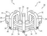
- FIG. 1is substantially a perspective bottom side view of one possible embodiment of the bone foundation guide the invention.
- FIG. 2is a top side perspective view of one possible embodiment of anchoring strut of the present invention.
- FIG. 3is a bottom side perspective view of one possible embodiment of anchoring strut of the present invention.
- FIG. 4is substantially a bottom side perspective view of one possible embodiment of the body.
- FIG. 5is substantially a perspective top side view of one embodiment of the bone foundation guide.
- FIG. 6is substantially a bottom elevation view of one embodiment of the bone foundation guide.
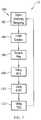
- FIG. 7is substantially a flow chart schematic showing a method of using the invention.
- FIG. 8is substantially an elevation view of patient's mouth showing exposed bone portion of the dental surgical site.
- FIG. 9is substantially an elevation view of patient's mouth showing exposed bone portion of the dental surgical site in an edentulous preoperative state.
- FIG. 10is substantially a perspective front view of one embodiment of the bone foundation guide with struts being applied to the dental surgical site.
- FIG. 11is substantially a front perspective view of the bone foundation guide with struts being bitten down upon by the patient.
- FIG. 12is a front perspective view of the bone foundation guide with struts with the patient releasing its grip on the bone foundation guide and the strut fasteners being removed.
- FIG. 13is substantially a front perspective view of the bone foundation guide with struts, the strut fasteners being removed from the respective strut.
- FIG. 14is substantially a front perspective view of the bone foundation guide with struts, the strut being removed the bone foundation guide body.
- FIG. 15is substantially a front perspective view of the bone foundation guide with struts removed and the harvested bone being removed from the dental surgical site.
- FIG. 15Ais substantially a bottom elevation view of the bone foundation guide with struts and the harvested bone removed from the dental surgical site.
- FIG. 16is substantially an underside elevation view of the bone foundation guide with struts removed and the harvested bone removed from the dental surgical site
- FIG. 17is substantially an underside perspective view of the combination bone foundation guide and dental implant surgical guide combination.
- FIG. 18is substantially an underside elevation view of the combination bone foundation guide and dental implant surgical guide combination.
- FIG. 19is substantially a cutaway, perspective view of the combination bone foundation guide and dental implant surgical guide combination.
- FIG. 20is substantially a perspective view of the tissue spacer gasket.
- FIG. 21is substantially a perspective view of the bone foundation guide with abutments attached to the implants.
- FIG. 22is substantially a perspective view of the bone foundation guide and tissue gasket combination
- FIG. 23is substantially a perspective view of the prosthesis applied to the bone foundation guide and tissue gasket combination.
- FIG. 24is substantially a perspective view of the dental surgical site with the bone foundation guide, tissue gasket and prosthesis removed.
- FIG. 25is substantially a perspective view of the dental surgical site with the bone foundation guide, tissue gasket and prosthesis removed and gum tissue sutured back into place at the dental surgical site.
- FIG. 26is substantially a perspective view of the dental surgical site with gum tissue sutured back into place and prosthesis relocated upon the implants.
- the present invention 10could be a bone foundation guide system 18 and method or process 100 .
- the bone foundation guide system 18could comprise a bone foundation guide 20 , a dental implant surgical guide 50 and in at least one embodiment, a tissue spacing gasket 80 as well.
- the bone foundation guide body 22 , the dental implant surgical guide 50 and tissue spacing gasket 80may be designed and created together through digital dentistry in which scans of the patient's mouth 35 (along with impressions and castings thereof) may be used to create a virtual model (not shown) of the patient's existing mouth; to develop a virtual model of the patient's mouth both pre-dental and post-dental surgery; and to develop a dental surgical plan that connects the two patient-specific virtual models.
- the dental surgical planningcan provide for the manufacture the bone foundation guide 20 , dental implant surgical guide 50 and tissue spacing gasket 80 so that the contours of the bone foundation guide body 22 may be created to fit upon the exposed bone 14 of the dental surgical site 12 .
- the dental implant surgical guide 50 contoursmay also match those of the dental implant surgical guide 50 and the tissue spacing gasket 80 to enable dental implant surgical guide 50 and the tissue spacing gasket 80 to alternately be removably attached to and be supported by the bone foundation guide 20 .
- the bone foundation guide 20as substantially used by a dental healthcare professional such as a dental surgeon (not shown) to substantially modify (e.g., reduce, augment or both) the bone 14 of the dental surgical site 12 as needed for a successful dental surgery.
- the bone foundation guide 20could comprise a bone foundation guide body 22 with a buccal wall 24 and lingual wall 26 connected together at their respective ends by a first end 28 and a second end 30 .
- the first end 28 and the second end 30could be holding the buccal and lingual walls 24 , 26 apart from one and other in a substantially parallel fashion to generally create and define an open surgical space 32 (e.g., that generally passes through the bone foundation guide body 22 ) to generally continuously connect a portion of the top 34 of the body 22 with a portion of the bottom 36 of the body 22 .
- the bone foundation guide body 22may be further penetrated by one or more attachment apertures 38 that may be oriented to pass through a buccal 24 wall.
- Body fasteners 40may pass through the attachment apertures 38 to into the bone 14 of the dental surgical site 12 to removably secure the bone foundation guide body 22 to dental surgical site 12 .
- the attachment aperture 38could further feature a reinforcement collar (not shown) to support and guide the fastener 40 through the attachment aperture 38 .
- the attachment apertures 38could pass though the body 22 connecting top 34 and bottom 36 or through the lingual wall 26 to provide body attachment to the dental surgical site 12 .
- the bodymay further have a cutting guard 23 extending up from the top of the lingual wall 26 to prevent a cutting implement (not shown) when used with the bone foundation guide in removing bone 14 from a dental surgical site from unwantedly cutting the tongue or other portions of the patient's mouth 19 .
- This cutting guard 23may further feature out or more cutouts 25 that may be used to anchor and align other portions.
- the bone foundation guide body 22may further comprise of a one or more anchoring struts 42 that may be removably attached to the buccal wall 24 and the lingual wall 26 between the first end 38 and the second end 30 .
- the anchoring strut 42may have at its outer apex 44 one or more indentations 46 that can match one or more portions of gum, dentition or both the patient's first or opposing alveolar ridge 28 (e.g., the opposing alveolar ridge 13 is located opposite of or opposing to the second alveolar ridge 15 that is supporting the dental surgical site 12 .
- the front end 43 of anchoring struts 42may be penetrated by strut apertures 47 that allow strut fasteners 49 (e.g., tapered pins) to penetrate through the anchoring strut 42 to the buccal wall 24 .
- the strut fasteners 49may removably attach to the anchoring strut 42 by the buccal wall 24 and be held in place by frictional force.
- the other or rear end 41 of the anchoring strut 42may have a strut groove 48 that fits over a respective cutout 25 .
- a tab 45 within the strut groove 48may be removably received within the respective cutout 25 to further reversibly attach the rear end 41 to the cutting guard 23 .
- the anchoring strut 42may allow the patient itself press at least a portion of gum tissue, dentition or both of the opposing alveolar ridge 13 upon at least one anchoring strut 42 of the bone foundation guide 21 to generally hold the bone foundation guide 21 in place upon the dental surgical site 12 (e.g., the exposed bone.)
- that portion of gum tissue, dentition or both of the opposing alveolar ridge 13could be received with the indentation(s) 46 .
- the patient's actione.g., substantially clamping down with patient's mouth upon the bone foundation guide 20 in situ could allow the patient to temporarily and removably hold the bone foundation dental upon the dental surgical site while the dental health care professional (not shown) is free to use both hands to attach the bone foundation guide 21 in place with body fasteners.
- the patientcould remove one or more portions of the opposing alveolar ridge 28 from the one or more indentations 46 upon the one or more anchoring struts 42 (e.g., the patient opens its mouth to stop biting upon the anchoring struts 42 .)
- the dental health care professionalcan then proceed with the removal of the strut fasteners 49 from the bone foundation guide 21 so as to be able to lift the anchoring struts 42 free and clear from the body 22 .
- anchoring struts 42can also be applied to bone reduction guides that lack the present inventions ability to combine or stack together with the dental implant surgical guide or tissue spacing gasket.
- bone reduction guidesare not contoured to accept the dental implant surgical guide or tissue spacing gasket but could have a body to which the anchoring struts 42 are applied to allow the patient to substantially clamping down with patient's mouth upon the bone reduction guide in situ could allow the patient to temporarily and removably hold the bone reduction guide upon the dental surgical site.
- the portions of dentition, teeth or both of the opposing alveolar ridgecould be received with the impressions located upon the apex of anchoring struts 42 to hold the bone reduction guide in place while the dental health care professional (not shown) is free to use both hands to attach the bone reduction guide in place with fasteners to the dental surgical site.
- the dental health care professional(not shown) is free to use both hands to attach the bone reduction guide in place with fasteners to the dental surgical site.
- the patientcould release its bite upon the anchoring struts.
- the dental healthcare professionalcan then remove the anchoring struts 42 from the body of the bone reduction guide to allow the bone reduction guide to be used to alter bone structure at the dental surgical site.
- the dental implant surgical guide 50could be removably attached to the top 34 of the body 22 .
- the dental implant surgical guide 50could be so anchored to dental surgical site 12 to generally allow dental implant surgical guide 50 to be substantially be used to guide and locate the placement of dental implants within dental surgical site 12 .
- the dental implant surgical guide 50could comprise a dental surgical guide body 20 having a first end side 52 and second end side 54 that terminates the dental surgical guide body 52 and along with a top side 58 and a bottom side 60 that continuously connect a buccal side 62 with a lingual side 64 .
- the bottom side 60 of the dental implant surgical guide 50can be digitally designed and manufactured to have a contour that substantially matches and removably accepts the top 34 of the bone foundation guide 20 .
- the top 34 of the bone foundation guide body 22may also be digitally designed and created to substantially match and to receive the bottom side 60 of the reciprocal dental surgical guide body 52 to allow the conjoining of the two guides 20 , 50 in a stackable manner so that the bone foundation guide 20 acts as a base or foundation for the dental implant surgical guide 50 .
- the dental surgical guide body 52can be further penetrated by one or more implant apertures 66 that could continuously connect the top side 58 to the bottom side 60 to guide implant preparation and attachment to the dental operation site 12 .
- the dental surgical guide body 52 to removably attach to the body 22could utilize a wide variety of attachment means.
- One such possible attachment meanscould make use one or more guide pins 70 and one or more guide tabs 71 and their frictional interplay with the body 22 .
- the guide pins 70could protrude out from the bottom side 60 by the buccal wall 62 to be removably received within pin apertures on the top 34 of the body 22 along the buccal wall 24 .
- the one or more guide tabs 71could extend outwards from the lingual side 64 to be respectively received by the cutouts 25 of the cutting guard 23 .
- the guide tabs 71 and guide pins 70 along with the lingual side 64 matching the contour of the cutting guard 23could provide a snap-in fit of the dental implant surgical guide 50 to the bone foundation guide 20 .
- the conjoining or stacking capability of the two guides 20 , 50could alleviate the need to remove the bone foundation guide 20 from the dental surgical site 12 prior to attaching the dental implant surgical guide 50 to the dental surgical site 12 as well as alleviate the need to attach the dental implant surgical guide 50 directly to the dental surgical site 12 and the like.
- This combining of the two guides 20 , 50could also reduce the time, money, effort, patient discomfort and alike that would otherwise occur if the guides 20 , 50 were used separately from one and other.
- the dental implant surgical guide 50generally surrounds the bone foundation guide's open surgical space 32 to allow implant components, implants or both to pass through the dental implant surgical guide's implant aperture(s) 66 and on through the of the open surgical space 32 .
- one other possible embodiment of the invention 10could further comprise a tissue spacing gasket 80 that can be alternatively used with the bone foundation guide 50 instead of the dental implant surgical guide 50 or the anchoring strut(s) 42 .
- the tissue spacing gasket 80could fit between the bottom 36 of the bone foundation guide 20 and the dental surgical site 12 to allow the proper placement of prosthesis 21 upon the placed implants by providing an approximation of the distance or thickness of the gum tissue 16 that otherwise covers the dental surgical site 12 .
- tissue spacing gasket 80upon the bone foundation guide top 34 where the tissue spacing gasket 80 is generally sandwiched between the bone foundation guide 20 and the prosthesis 21 could allow the tissue spacing gasket 80 provide additional benefits besides correcting for thickness of the missing (e.g., peeled back) gum tissue 16 .
- the tissue spacer guide 80could help cradle the prosthesis and maintain the prosthesis proper vertical and centric positions as the prosthesis is being fixed upon the implants.
- dental acryliccould be injected into the prosthesis to secure implant abutments to the prosthesis.
- the tissue spacing gasket 80could help block out the undercut of the abutments 17 to generally prevent the acrylic from reaching the undercuts and thus preventing unwanted or premature attachment of the prosthesis to the implants 17 .
- the tissue spacing gasket 80could further prevent acrylic from reaching and contaminating the exposed bone 14 .
- the tissue spacing gasket 80could be made from a pliable polymer that forms a gasket top 84 upon which the prosthesis could rest and to a gasket bottom 82 which is reversibly received by the bone foundation top 34 , the gasket top 84 and the gasket bottom 84 being continually connected by one or more gasket apertures 86 .
- the one or more gasket apertures 86could have the same alignment and size of the implant apertures 66 of the dental implant surgical guide 50 .
- the tissue spacing gasket 80could denote a gasket open surgical space (not shown) that continuously connects gasket top 84 and gasket bottom 82 , the gasket open surgical space generally matching the footprint of the bone foundation guide's open surgical space 32 .
- the tissue spacing gasket 80could have one or more gasket pins that protrude from the gasket bottom 82 and could be removably received within apertures on the bone foundation guide top 34 by the buccal wall 24 that received guide pins 70 .
- the tissue spacing gasket 80could further have the gasket tabs 88 that could be removably be received within the cutting guard cutouts 25 .
- the tissue spacing gasket tabs 88could generally match the size, placement and orientation of the dental implant surgical guide's guide tabs 71
- one possible method or process 100 for the use of the inventioncould start with step 102 , digital scanning and modeling for the patient-specific dental surgery.
- dental digital methodsmay be used in creating patient-specific map of the patient's mouth (which could include the digital scanning of analogue appliances such as patient specific castings and impressions); in creating models for patient-specific bone remodeling (e.g., foundation and re-contouring) of the upper and/or lower dental struts in the patient's mouth; in creating models for dental implant surgical guides/bone foundation guides and prosthetics used post-patient-specific bone remodeling; in creating a patient specific model of the patient's mouth post dental surgery.
- the process 100could proceed to step 104 , creation of the guides, tissue spacing gasket and other dental appliances.
- the acquired and processed modeling datacan be used to create the patient-specific bone foundation guide (e.g., d patient-specific bone foundation guide, tissue spacing gasket and dental implant surgical guide that be stacked together in various combinations.
- the anchoring strutscan also be patient-specific made to have indentations at their respective apexes to match various portions of the dentition, tissue or both of the opposing alveolar ridge.
- the anchoring strutscould be removably attached to the bone foundation body.
- the strut fastenere.g., a tapered pin
- the strut rear endcould removably straddle the cutting guard's respective cutout with the strut groove allowing the strut groove's tab to be removably received within the cutout.
- the design and manufacturing imparted stacking capabilitycould allow the two guides and gasket to come together to various stacked combinations.
- This stacking capabilityallows the bone foundation guide, once removably secured to the dental surgical site by the dental health care profession, to generally act as foundation for the dental implant surgical guide or the spacing tissue gasket to secure them alternately to the dental surgical site.
- This stacking capabilitycould allow the implant, implant components, implant instruments and the like to be guided through the dental implant surgical guide implant apertures and the bone foundation guide's open surgical space to properly interact with the dental surgical site.
- the process 100could proceed to step 106 , surgical prep.
- step 106surgical prep
- the dental health care professionalcould (after properly anesthetizes the patient and instituting other required dental surgical pre-operation protocols) could make incisions in the gum area of the dental surgical site, and peel back the gum tissue to expose the portion of bone being operated upon at the dental surgical site. Any teeth at the dental implant surgical site can be removed. If the patient's dental health has declined enough, the alveolar ridge supporting the dental surgical site could be made edentulous After this step is substantially completed, the process 100 could proceed to step 108 , use of the bone foundation guide.
- the bone foundation guideis initially placed upon to the dental surgical site (e.g., the open surgical space being contoured to generally match and receive segment of the exposed bone.)
- the dental healthcare professionalthan asks the patient to “bite” down upon or “bite” up against) the bone foundation guide (e.g., using the portion of the dentition, tissue or both of the opposing alveolar ridge) to substantially hold the bone foundation guide initially in place upon the dental surgical site.
- the portion of the dentition, tissue or both of the opposing alveolar ridgecomes in contact with the anchoring strut(s) the portion may be received within the one or more indentations on the apex(s) of the anchoring strut(s).
- the dental healthcare professional with both hands freecan then use a drill to make channels in the dental surgical site (e.g., the exposed bone portion) utilizing the attachment apertures.
- Body fastenersare placed into the attachment apertures and channels to generally removably attach the bone foundation guide to the exposed bone at the dental surgical site.
- the dental healthcare professionalaskes the patient to relax its grip upon the bone foundation guide to generally bring the portion of the dentition, tissue or both of the opposing alveolar ridge out of contact with the indentation(s).
- the strut fastener(s)can be removed along with the anchoring strut(s) from the bone foundation guide.
- the removal of the anchoring struts from the bone foundation guide's topclears top so the top can be used to guide a cutting implement (e.g., blade saw) to reduce the dental surgical site's bone structure.
- the harvested boneor bone analogue
- Known dental techniques for reducing or augmenting the bonecould be employed to provide the proper bone contour for the dental surgical site.
- the dental health care professionalcould place the bottom side of the dental implant surgical guide upon the top of the bone foundation guide generally enclosing the open surgical space.
- the tissue spacing gasketis sandwiched between the bone foundation guide and the dental implant surgical guide. Pins on the underside of the dental implant surgical guide could attach to the attachment apertures in the bone foundation guide top (e.g., by the buccal wall) while the guide tabs extending out from the lingual side could removably engage the cutting guard cutouts to provide a snap fit of the dental implant surgical guide into the bone foundation guide.
- the dental healthcare professionalcould use the bone foundation guide and the dental implant surgical guide stacked or otherwise combined together to substantially direct and operate implant preparation implements (e.g., drills, reamers, and the like), implant components, or both by passing them through the dental implant surgical guide and into the open surgical space to properly prepare the dental surgical site to receive the implant(s)
- implant preparationcould ensure there was proper orientation and telemetry of the implant components and implants into the generally exposed bone of the dental surgical site.
- the implant(s)could then pass through the combination to be anchored into the bone.
- the process 100could proceed to step 112 , using tissue spacing gasket.
- the surgical implant dental guidecould be removed from the bone foundation guide and the tissue spacer gasket could alternatively be connected to the bone foundation guide.
- the pins located on the gasket bottomcan be generally be removably received in the same apertures on the bone foundation guide top that the accommodated the guide pins of the dental implant surgical guide.
- tissue spacing gasketis removably attached to the bone foundation guide then temporary abutments can be placed upon the implants.
- a temporary prosthesiscan be placed over the tissue spacer gasket to come into contact the temporary abutments.
- the tissue spacing gasketcould cradle the temporary prosthesis at this point holding it in the proper vertical and concentric orientation as dental acrylic is injected into the temporary prosthesis to secure the abutments to the temporary prosthesis.
- the tissue spacing gasketmay further prevent the acrylic from leaking upon and contaminating the exposed bone.
- the tissue spacing gasketmay as well as prevent any acrylic leaking onto the abutment undercut (e.g., to generally prevented unwanted premature attachment of the prosthesis to the implants.)
- the tissue spacing gasketmay help to insure that proper distance between bone and prosthesis is maintained to account for presence of tissue when the gum tissue is placed back over the bone.
- the above abutment prosthesis attachment processmay repeated used for a clear or analogue prosthesis that later can be sent back to the lab.
- the analogue prosthesis with its affixed abutmentsmay be applied to implant bone model that was devised through the dental model to see how the dental healthcare professional may have deviated from the original dental surgical plan in attaching the implants to the dental surgical site.
- the analogue prosthesiswill allow the final changes of the actual dental surgery (on site changes made by the dental healthcare professional to take into account issues not foreseen by the dental surgical plan) to be imparted onto the dental model and to the final prosthesis.
- the tissue spacing gasketcould be removed from the bone foundation guide.
- the gum tissue flapscould be sutured back over the exposed bone (but not necessarily over the implants) and the temporary prosthesis could be reattached to the implants.
- the temporary prosthesiscould help maintain the implant positioning as set during the surgery, so that the permanent prosthesis should be able to replace the temporary prosthesis with minimal adjustment and fitting.
- This process 100could also allow as needed, use of temporary cylinder, associated seals, additional filling, and other sealing methods that may be used to properly prepare the dental implant for the attachment of prosthesis and the like. If healing abutments are used instead, then they can be fitted to the implants as needed. The gum tissues can then be sutured or otherwise cover-up the exposed bone to meet up with the abutment/implants. If the gum tissues need to heal or need to heal around the healing abutments or the implants require ossification to secure them in place to the bone, then after these event(s) have occurred/or a suitable amount of healing time has passed then the final prosthesis (or prosthetic) could be placed upon the implants in a secure fashion. After this step is substantially completed, the process 100 could proceed back to step 102 as needed.
- a bone foundation guideprovides for the combining or stacking together as one unit, a bone foundation guide, a dental implant surgical guide and tissue spacing gasket.
- the use of removable anchoring strutsallows the patient to apply the opposing alveolar ridge to the apex of the one or more removable anchoring struts to initially hold the bone foundation guide in place upon the dental surgical site. The action frees the dental healthcare professional to use both hands to more securely attach the bone foundation guide to the dental implant site with fasteners.
- the patientcan remove opposing alveolar ridge from the anchoring struts to allow the anchoring struts to be removed from bone foundation guide to expose the top for bone reduction actions (or bone augmentation actions.)
- the strut removalallows the tissue spacing gasket and dental implant surgical guide to be alternatively used with the bone foundation guide in generally securely stacked manner for use upon the dental surgical site for the placement and attachment of one or more dental implants at the dental surgical site.
Landscapes
- Health & Medical Sciences (AREA)
- Oral & Maxillofacial Surgery (AREA)
- Dentistry (AREA)
- Epidemiology (AREA)
- Life Sciences & Earth Sciences (AREA)
- Animal Behavior & Ethology (AREA)
- General Health & Medical Sciences (AREA)
- Public Health (AREA)
- Veterinary Medicine (AREA)
- Orthopedic Medicine & Surgery (AREA)
- Dental Prosthetics (AREA)
Abstract
Description
- to provide an dental implant surgical guide that removably combines with a bone foundation guide to properly place a dental implant-retained prosthesis to a dental surgical site in a manner that reduces patient stress and bruising that may occur than if the two guides were applied separately;
- the ability to use a digital virtual model of patent mouth to design a bone foundation guide wherein both the bone foundation guide and a dental implant surgical guide can be conjoined in situ properly locate a one or more dental implants that could be used to locate and secure a fixed dental prosthetic;
- to provide a bone foundation guide and dental implant surgical guide that can be combined together to substantially reduce cost, time and man-hours needed in a dental implant surgical procedure to properly locate and attach a dental prosthetic to a dental surgical site;
- the ability to use digital dentistry to control the design and manufacture of a dental implant surgical guide-bone foundation guide combination in a manner that digitally controls and refines the accuracy of the resulting bone foundation guide; dental implant surgical guide and a final fixed prosthetic; and
- to provide a bone foundation guide that is used in conjunction with a tissue spacing gasket, the tissue spacing gasket being used to help properly locate the placement of a prosthesis relative to the placed dental implant(s) by generally taking into account the height (or depth) of gum tissue that could normally cover the exposed bone at the dental implant surgical site;
- the ability to design and manufacture a bone foundation guide system wherein a dental implant surgical guide or a tissue spacing gasket that could alternatively could mate and interlock with the bone foundation to generally allow implant components, dental implant or both to pass through the assembled combination onto the bone at a dental surgical guide;
- to provide a dental surgical implant guide, bone foundation guide, and tissue spacing gasket to have matching contours and aligned openings and apertures that allow guides and gasket to be assembled into combinations to properly locate and attach a fixed prosthetic to an implant at a dental surgical site;
- to provide one or more anchoring struts that could removably and temporarily attach to the front and back of the base of a bone foundation guide, each anchoring strut at a respective apex further define one or more indentations can reversibly receive one or more portions of the tissue, dentition or both of an alveolar ridge that is located opposite of an alveolar ridge that is supporting the dental surgical site;
- the ability to have the patient bring one or more portions of the dentition, gum tissue or alike of an alveolar ridge into contact with the anchoring struts to hold the bone foundation guide in place upon the dental surgical site located on the opposing alveolar ridge;
- to provide anchoring struts that can be removed from the bone foundation guide after the bone foundation guide has been secured to the dental surgical site by fasteners; and
- the ability to have the patient temporarily hold the bone foundation guide in place upon the dental surgical site so as to free the dental health care professional from holding the bone foundation guide in place and being able to concentrate instead on securing the bone foundation guide to the dental surgical site with one or more fasteners.
Claims (20)
Priority Applications (3)
| Application Number | Priority Date | Filing Date | Title |
|---|---|---|---|
| US16/529,861US11065083B2 (en) | 2013-03-14 | 2019-08-02 | Bone foundation guide system and method |
| US17/351,794US11344383B2 (en) | 2015-10-23 | 2021-06-18 | Bone foundation guide system and method |
| US17/826,249US11950974B2 (en) | 2015-10-23 | 2022-05-27 | Bone foundation guide system and method |
Applications Claiming Priority (4)
| Application Number | Priority Date | Filing Date | Title |
|---|---|---|---|
| US201361784029P | 2013-03-14 | 2013-03-14 | |
| US14/214,555US10307226B2 (en) | 2013-03-14 | 2014-03-14 | Bone foundation guide and method of use |
| US14/921,111US10398530B2 (en) | 2013-03-14 | 2015-10-23 | Bone foundation guide system and method |
| US16/529,861US11065083B2 (en) | 2013-03-14 | 2019-08-02 | Bone foundation guide system and method |
Related Parent Applications (1)
| Application Number | Title | Priority Date | Filing Date |
|---|---|---|---|
| US14/921,111ContinuationUS10398530B2 (en) | 2013-03-14 | 2015-10-23 | Bone foundation guide system and method |
Related Child Applications (1)
| Application Number | Title | Priority Date | Filing Date |
|---|---|---|---|
| US17/351,794ContinuationUS11344383B2 (en) | 2015-10-23 | 2021-06-18 | Bone foundation guide system and method |
Publications (2)
| Publication Number | Publication Date |
|---|---|
| US20190388184A1 US20190388184A1 (en) | 2019-12-26 |
| US11065083B2true US11065083B2 (en) | 2021-07-20 |
Family
ID=55266555
Family Applications (4)
| Application Number | Title | Priority Date | Filing Date |
|---|---|---|---|
| US14/921,111Active2035-08-06US10398530B2 (en) | 2013-03-14 | 2015-10-23 | Bone foundation guide system and method |
| US16/529,863ActiveUS11000346B2 (en) | 2013-03-14 | 2019-08-02 | Bone foundation guide system and method |
| US16/529,861ActiveUS11065083B2 (en) | 2013-03-14 | 2019-08-02 | Bone foundation guide system and method |
| US17/231,140Active2034-09-19US11779434B2 (en) | 2013-03-14 | 2021-04-15 | Bone foundation guide system and method |
Family Applications Before (2)
| Application Number | Title | Priority Date | Filing Date |
|---|---|---|---|
| US14/921,111Active2035-08-06US10398530B2 (en) | 2013-03-14 | 2015-10-23 | Bone foundation guide system and method |
| US16/529,863ActiveUS11000346B2 (en) | 2013-03-14 | 2019-08-02 | Bone foundation guide system and method |
Family Applications After (1)
| Application Number | Title | Priority Date | Filing Date |
|---|---|---|---|
| US17/231,140Active2034-09-19US11779434B2 (en) | 2013-03-14 | 2021-04-15 | Bone foundation guide system and method |
Country Status (2)
| Country | Link |
|---|---|
| US (4) | US10398530B2 (en) |
| AU (1) | AU2015301385A1 (en) |
Families Citing this family (29)
| Publication number | Priority date | Publication date | Assignee | Title |
|---|---|---|---|---|
| US10363115B2 (en)* | 2011-09-16 | 2019-07-30 | Ibur, Llc | Method of using an endentulous surgical guide |
| US9539069B2 (en) | 2012-04-26 | 2017-01-10 | Zimmer Dental, Inc. | Dental implant wedges |
| US9554877B2 (en)* | 2012-07-31 | 2017-01-31 | Zimmer, Inc. | Dental regenerative device made of porous metal |
| US9408678B2 (en) | 2012-10-10 | 2016-08-09 | James Harrison | Cradle for positioning a final dental prosthesis and a system incorporating the cradle |
| US10278789B2 (en) | 2013-03-14 | 2019-05-07 | National Dentex, Llc | Bone foundation guide system and method |
| US10639129B2 (en) | 2013-03-14 | 2020-05-05 | National Dentex, Llc | Bone foundation guide system and method |
| US10307226B2 (en) | 2013-03-14 | 2019-06-04 | National Dentex, Llc | Bone foundation guide and method of use |
| US10398530B2 (en)* | 2013-03-14 | 2019-09-03 | National Dentex, Llc | Bone foundation guide system and method |
| US10405945B2 (en) | 2013-03-14 | 2019-09-10 | National Dentex, Llc | Bone foundation guide and method of use |
| US20160228211A1 (en)* | 2014-11-14 | 2016-08-11 | Tuan Anh Pham | Crown assistance device |
| EP3364908A1 (en)* | 2015-10-23 | 2018-08-29 | Daniel R. Llop | Bone foundation guide system and method |
| CA3015801A1 (en)* | 2016-03-05 | 2017-09-14 | National Dentex, Llc | Bone foundation guide system and method |
| US10016242B2 (en)* | 2016-06-06 | 2018-07-10 | Neocis Inc. | Splint device for forming a fiducial marker for a surgical robot guidance system, and associated method |
| CA3036721A1 (en)* | 2016-09-30 | 2018-04-05 | National Dentex, Llc | Bone foundation guide and method of use |
| CA3060106A1 (en)* | 2017-04-20 | 2018-10-25 | Shenzhen Aheadfit Technology Co., Ltd | Bote controlled drill-head guide plate and manufacturing method thereof |
| WO2018213817A1 (en) | 2017-05-18 | 2018-11-22 | Jason Watson | Fixation base and guides for dental prosthesis installation |
| US11160639B2 (en) | 2018-01-19 | 2021-11-02 | Mark Elliot Palmer | Dental alignment system and method for dental implant placement |
| US11504210B2 (en) | 2018-07-13 | 2022-11-22 | National Dentex, Llc | Dental bone foundation guide with palatal or lingual side gap and freehand surgical guide |
| US11510763B2 (en) | 2018-07-20 | 2022-11-29 | National Dentex, Llc | Method of establishing upper boundary for dental prosthetic |
| US11284967B2 (en)* | 2018-11-08 | 2022-03-29 | Swissmeda Ag | Bone foundation guide system with reduction guide |
| US11213367B2 (en) | 2018-12-21 | 2022-01-04 | National Dentex, Llc | Dental bone foundation guide with bur instrument guide features |
| US11723844B2 (en) | 2019-03-26 | 2023-08-15 | National Dentex, Llc | Nanoceramic dental prosthetic |
| US11819382B2 (en) | 2019-05-09 | 2023-11-21 | DDS Company, Inc. | Tissue borne fixation system, device, and methods of making and using same |
| CN211674655U (en)* | 2019-07-05 | 2020-10-16 | 儒蓉(成都)医疗科技有限公司 | Composite guide plate |
| CN110478065B (en)* | 2019-07-05 | 2021-06-22 | 儒蓉(成都)医疗科技有限公司 | Tooth-supported guide, mucosa-supported guide, bone-supported guide, and methods of making and using the same |
| CN110384564B (en)* | 2019-09-02 | 2025-01-24 | 邹德荣 | Overlapping Oral Implant Surgery Guide System |
| CN114081649A (en)* | 2021-11-19 | 2022-02-25 | 深圳市宏盛义齿技术有限公司 | Novel combined guide plate |
| USD1006225S1 (en) | 2022-03-17 | 2023-11-28 | DDS Company, Inc. | Foundation guide seating site |
| CN116831759A (en)* | 2022-03-23 | 2023-10-03 | 朱裕华 | Three-point positioning dental positioning guide and its three-point positioning modeling method |
Citations (113)
| Publication number | Priority date | Publication date | Assignee | Title |
|---|---|---|---|---|
| US3886661A (en)* | 1970-08-27 | 1975-06-03 | Neill Tech Inc | Dental prosthetic device teaching aid |
| US5018970A (en) | 1987-12-17 | 1991-05-28 | Stordahl Finn R | Implant teeth--permanent bases with replaceable caps |
| US5725376A (en) | 1996-02-27 | 1998-03-10 | Poirier; Michel | Methods for manufacturing a dental implant drill guide and a dental implant superstructure |
| US5967777A (en) | 1997-11-24 | 1999-10-19 | Klein; Michael | Surgical template assembly and method for drilling and installing dental implants |
| US6319006B1 (en) | 1999-11-03 | 2001-11-20 | Sirona Dental Systems Gmbh | Method for producing a drill assistance device for a tooth implant |
| US6382975B1 (en) | 1997-02-26 | 2002-05-07 | Technique D'usinage Sinlab Inc. | Manufacturing a dental implant drill guide and a dental implant superstructure |
| US6491696B1 (en) | 1998-05-20 | 2002-12-10 | Medicon Chirurgiemechaniker-Genossenschaft | Device for distracting bone segments, especially in the area of a jaw |
| US6672870B2 (en) | 2001-03-20 | 2004-01-06 | John G. Knapp | Method and instrumentation for attaching dentures |
| US6814575B2 (en) | 1997-02-26 | 2004-11-09 | Technique D'usinage Sinlab Inc. | Manufacturing a dental implant drill guide and a dental implant superstructure |
| US6997707B2 (en) | 2000-11-13 | 2006-02-14 | Yves Germanier | Positioning device for fitting implant-supported dental prostheses |
| US20060166169A1 (en) | 2002-03-06 | 2006-07-27 | Nobel Biocare Ab (Publ) | Fixture for orthodontic anchorage and osseo distraction of the alveolar process, and for the stabilization of temporary prostheses |
| US20060263764A1 (en) | 2003-02-27 | 2006-11-23 | Nucleonics Inc. | Methods and constructs for evaluation of rnai targets and effector molecules |
| US20070162014A1 (en) | 2005-07-02 | 2007-07-12 | Greater Glasgow Health Board (South Glasgow University Hospitals Division) | Supra-mucosal bone fixation apparatus and method |
| US7331786B2 (en) | 1996-02-27 | 2008-02-19 | Technique D'usinage Sinlab Inc. | Manufacturing a dental implant drill guide and a dental implant superstructure |
| US20090092948A1 (en) | 2007-10-03 | 2009-04-09 | Bernard Gantes | Assisted dental implant treatment |
| US20090274990A1 (en) | 2006-09-25 | 2009-11-05 | Imagnosis Inc. | Implantation Guide Making Method and Guide Block |
| US20090298008A1 (en) | 2008-05-29 | 2009-12-03 | Ibur, L.L.C. | Dental x-ray and drill guide apparatus and method |
| US7632097B2 (en) | 2001-07-06 | 2009-12-15 | Dental Vision B.V.B. | Method for manufacturing a suprastructure and a corresponding drill jig |
| US20100035201A1 (en) | 2008-08-10 | 2010-02-11 | Israel Beck | Universal Template Enabling Drilling and Placing a Dental Implant Into A Patient's Jaw |
| US20100124731A1 (en) | 2008-11-18 | 2010-05-20 | Ibur, Llc | Dental device and method for linking physical and digital data for diagnostic, treatment planning, patient education, communication, manufacturing, and data transfer purposes |
| WO2010061391A1 (en) | 2008-11-28 | 2010-06-03 | Rad Dental Devices Ltd. | Bidirectional alveolar ridge distractor |
| US7774084B2 (en) | 2006-07-28 | 2010-08-10 | 3M Innovative Properties Company | Computer-aided implanting of orthodontic anchorage devices using surgical guides |
| US7824181B2 (en) | 2004-05-04 | 2010-11-02 | Materialise Dental Nv | Custom-fit implant surgery guide and associated milling cutter, method for their production, and their use |
| US20100316974A1 (en) | 2009-06-11 | 2010-12-16 | Pou Yu Biotechnology Co., Ltd. | Method of making a surgical template used for a computer-guided dental implant surgery |
| US20110033819A1 (en) | 2007-10-31 | 2011-02-10 | Sicat Gmbh & Co.Kg | Method for producing a treatment jig |
| US7887327B2 (en) | 2001-08-31 | 2011-02-15 | Leonard Marotta | Accurate analogs for prostheses using computer generated anatomical models |
| US20110045431A1 (en) | 2008-11-18 | 2011-02-24 | Groscurth Randall C | Bone screw linking device |
| US20110045432A1 (en) | 2008-11-18 | 2011-02-24 | Groscurth Randall C | Simple linking device |
| US7905726B2 (en) | 2006-10-10 | 2011-03-15 | Stumpel Lambert J | Surgical guide for dental implant and methods therefor |
| US7909606B2 (en) | 2006-12-21 | 2011-03-22 | Marcello Marchesi | Method for planning and performing dental treatments |
| US20110111371A1 (en) | 2009-11-11 | 2011-05-12 | Jerome Haber | Computer-aided design of a thin-layer drill guide |
| US7942668B2 (en) | 2005-06-03 | 2011-05-17 | Nobel Biocare Services Ag | Drill template arrangement |
| US20110151399A1 (en) | 2008-08-29 | 2011-06-23 | De Clerck Rene | Method and transfer element for manufacturing a superstructure and a corresponding template |
| US20110207084A1 (en) | 2010-01-13 | 2011-08-25 | Kaigler Sr Darnell | Method and apparatus for bone distraction |
| US8011927B2 (en) | 2008-04-16 | 2011-09-06 | Biomet 3I, Llc | Method for pre-operative visualization of instrumentation used with a surgical guide for dental implant placement |
| US8038440B2 (en) | 2003-02-28 | 2011-10-18 | Materialise Dental N.V. | Method for placing and manufacturing a dental superstructure, method for placing implants and accessories used thereby |
| CA2795668A1 (en) | 2010-04-29 | 2011-11-03 | Synthes Usa, Llc | Orthognathic implant and methods of use |
| WO2012007615A2 (en) | 2010-07-16 | 2012-01-19 | Universitat Autonoma De Barcelona | Dental-implant planning method |
| US20120046914A1 (en) | 2010-08-20 | 2012-02-23 | Fei Gao | Hybrid method for dental implant treatment planning |
| EP2425797A1 (en) | 2010-09-02 | 2012-03-07 | Marcus Abboud | Implant assistance assembly for implanting a jaw implant |
| US8135492B2 (en) | 2009-03-19 | 2012-03-13 | Pou Yu Biotechnology Co., Ltd. | Method of making a surgical template used for a computer-guided dental implant surgery |
| US8142189B2 (en) | 2001-12-28 | 2012-03-27 | Noble Biocare Services AG | Arrangement and device for using a template to form holes for implants in bone, preferably jaw bone |
| US8272870B2 (en) | 2006-11-03 | 2012-09-25 | Materialise Dental N.V. | Device for securing a dental attachment to an implant |
| US20120261848A1 (en) | 2009-12-23 | 2012-10-18 | Haraszati Gyoergy | Method to create removable dental prosthesis, and the dental prosthesis making thereof |
| US20120277899A1 (en) | 2010-05-05 | 2012-11-01 | James Jiwen Chun | Computer-aided Fabrication Of A Removable Dental Prosthesis |
| US20130011813A1 (en) | 2010-03-05 | 2013-01-10 | Jose Alvarez Garcia | Prosthesis for dental implants |
| US20130023888A1 (en) | 2011-07-22 | 2013-01-24 | Woncheol Choi | Surgical drill guide adapter with a handle and detachable head |
| US8364301B2 (en) | 2006-10-07 | 2013-01-29 | Bankruptcy Estate Of Voxelogix Corporation | Surgical guides and methods for positioning artificial teeth and dental implants |
| US8371849B2 (en) | 2010-10-26 | 2013-02-12 | Fei Gao | Method and system of anatomy modeling for dental implant treatment planning |
| US20130071811A1 (en)* | 2011-09-16 | 2013-03-21 | Randall C. Groscurth | Edentulous surgical guide |
| US20130209956A1 (en) | 2009-02-04 | 2013-08-15 | Mid Corp. | System, method and apparatus for implementing dental implants |
| US8529255B2 (en)* | 2009-01-16 | 2013-09-10 | V2R Biomedical Inc | Dental prosthesis system |
| US8540510B2 (en) | 2006-05-04 | 2013-09-24 | Nobel Biocare Services Ag | Device for securing a dental implant in bone tissue, a method for making a surgical template and a method of securing a dental implant in bone tissue |
| US20130252202A1 (en) | 2011-03-21 | 2013-09-26 | Roland Pardeller | Method for planning a dental prosthesis implant arrangement and a reference arrangement |
| US8574302B2 (en) | 2010-12-20 | 2013-11-05 | Warsaw Orthopedic, Inc. | Bone augmentation device |
| US8585402B2 (en) | 2008-08-29 | 2013-11-19 | Zimmer Dental, Inc. | Dental drill guide system |
| WO2013181721A2 (en) | 2012-06-05 | 2013-12-12 | Dental Vision B.V.B.A | Method for manufacturing a template to adapt the shape of a bone defect in a jaw to a bone superstructure |
| US20140026419A1 (en) | 2012-07-27 | 2014-01-30 | Guided Surgery Solutions, Llc | Surgical guide fabrication |
| US20140080086A1 (en) | 2012-09-20 | 2014-03-20 | Roger Chen | Image Navigation Integrated Dental Implant System |
| US20140080092A1 (en) | 2012-09-14 | 2014-03-20 | Biomet 3I, Llc | Temporary dental prosthesis for use in developing final dental prosthesis |
| US8706672B2 (en) | 2007-04-18 | 2014-04-22 | Dentsply Implants Nv | Computer-assisted creation of a custom tooth set-up using facial analysis |
| US8720037B2 (en) | 2011-04-07 | 2014-05-13 | Marcus Abboud | Method for making a dental guide channel |
| US8777612B2 (en) | 2007-11-16 | 2014-07-15 | Biomet 3I, Llc | Components for use with a surgical guide for dental implant placement |
| WO2014130536A1 (en) | 2013-02-19 | 2014-08-28 | Global Dental Science Llc | Removable system and method for dentures and surgical guides |
| US8827699B2 (en) | 2007-05-25 | 2014-09-09 | Trevor BAVAR | Surgical drill guide and index system |
| US20140255876A1 (en) | 2012-04-17 | 2014-09-11 | Poly Virtual Occlusion, LLC | Systems and Methods for Analyzing Dynamic Dental Occlusions and Making Dental Appliances |
| US8899984B2 (en) | 2009-05-20 | 2014-12-02 | Daniel R. Llop | CT-based, side-loading surgical and laboratory dental implant guide system and method |
| US20150025855A1 (en) | 2011-12-21 | 2015-01-22 | 3Shape A/S | Virtually designing a customized healing abutment |
| US20150030995A1 (en) | 2011-10-25 | 2015-01-29 | Safe Surgery S.R.L. | Method for calculating the final position of a dental implant to be implanted in a patient's mouth in a hole made with the aid of a surgical template |
| US8956158B2 (en) | 2011-12-29 | 2015-02-17 | Swissmeda Ag | Surgical template for performing dental implantology |
| CA2934371A1 (en) | 2013-12-19 | 2015-06-25 | Trispera Dental Inc. | System and method for recording a bite of an edentulous individual |
| US9069914B2 (en) | 2003-04-03 | 2015-06-30 | Align Technology, Inc. | Method and system for fabricating a wax model of a dental coping configured to fit a tooth preparation |
| MX2014001163A (en) | 2014-01-29 | 2015-07-29 | Mageotec S A De C V | Method for manufacturing surgical guides for placing implant-supported tooth prosthesis. |
| US9107723B2 (en) | 2005-11-22 | 2015-08-18 | Benson Luther Hall | System and method for the design, creation and installation of implant-supported dental prostheses |
| WO2015148891A2 (en) | 2014-03-28 | 2015-10-01 | Jason Watson | Dental device comprising surgical template and false teeth set and related methods |
| US9155548B2 (en) | 2013-03-12 | 2015-10-13 | Hsieh-Hsing Lin | Positioning device for bone drilling |
| US9155599B2 (en) | 2010-11-03 | 2015-10-13 | Global Dental Science Llc | Systems and processes for forming anatomical features in dentures |
| US9161822B2 (en) | 2008-11-26 | 2015-10-20 | In'tech Industries, Inc. | Conformance model |
| US9168112B2 (en) | 2012-07-27 | 2015-10-27 | Guided Surgery Solutions, Llc | Multi-layer surgical guide |
| US9173723B2 (en) | 2012-10-10 | 2015-11-03 | James Harrison | Method of installing a final dental prosthesis |
| US9211165B2 (en) | 2014-03-19 | 2015-12-15 | GRS Guide System, Inc. | Positioning and installing surgical drilling devices and related devices and systems |
| US9226801B2 (en) | 2010-03-08 | 2016-01-05 | Ibur, Llc | Custom linkable imaging and multifunctional tray |
| US9259291B2 (en) | 2007-10-03 | 2016-02-16 | Cyber-Implants, LLC | Assisted dental implant treatment and replication system |
| US9283055B2 (en) | 2014-04-01 | 2016-03-15 | FPJ Enterprises, LLC | Method for establishing drill trajectory for dental implants |
| US9308055B2 (en) | 2012-07-25 | 2016-04-12 | 3Shape A/S | Designing a dental positioning jig |
| US9336336B2 (en) | 2010-06-29 | 2016-05-10 | 3Shape A/S | 2D image arrangement |
| US20160128810A1 (en) | 2013-06-12 | 2016-05-12 | Maxillent Ltd. | Guided sinus lift |
| US9358082B2 (en) | 2009-11-16 | 2016-06-07 | Nobel Biocare Services Ag | System and method for planning and/or producing a dental prosthesis |
| US9381072B2 (en) | 2010-04-29 | 2016-07-05 | DePuy Synthes Products, Inc. | Orthognathic implant and methods of use |
| US9402698B2 (en) | 2010-11-03 | 2016-08-02 | Global Dental Service LLC | Systems and processes for forming anatomical features in dentures |
| US9408678B2 (en) | 2012-10-10 | 2016-08-09 | James Harrison | Cradle for positioning a final dental prosthesis and a system incorporating the cradle |
| US20160278878A1 (en) | 2014-09-19 | 2016-09-29 | Jason Watson | Sequential dental surgical guide system and related methods |
| US9504538B2 (en) | 2001-04-13 | 2016-11-29 | Orametrix, Inc. | Unified three dimensional virtual craniofacial and dentition model and uses thereof |
| US9585730B2 (en) | 2014-03-18 | 2017-03-07 | Dio Corporation | Dental implant insertion set and manufacturing method thereof |
| US9649178B2 (en) | 2011-12-22 | 2017-05-16 | Mohamed Ikbal Ali | Devices and methods for enhancing bone growth |
| US9675796B2 (en) | 2013-11-10 | 2017-06-13 | Brainsgate Ltd. | Implant and delivery system for neural stimulator |
| US9700380B2 (en) | 2015-04-01 | 2017-07-11 | Dio Corporation | Method for providing guide information of operation using surgical guide |
| US9730777B2 (en) | 2013-03-08 | 2017-08-15 | James R. Glidewell Dental Ceramics, Inc. | Simplified protocol for fixed implant restorations using intra-oral scanning and dental CAD/CAM |
| US20170252126A1 (en) | 2013-03-14 | 2017-09-07 | Daniel R. Llop | Bone foundation guide system and method |
| US9795458B2 (en) | 2013-03-15 | 2017-10-24 | National Dentex, Llc | Dental surgical implant guide and prosthesis combination and method of use |
| US9801699B2 (en) | 2013-03-14 | 2017-10-31 | Devin Okay | Paired templates for placing dental implants and enhancing registration for denture prosthetics attached to the implants |
| US9848836B2 (en) | 2008-04-15 | 2017-12-26 | Biomet 3I, Llc | Method of creating an accurate bone and soft-tissue digital dental model |
| US9848965B2 (en) | 2014-12-05 | 2017-12-26 | Dio Corporation | Method for manufacturing surgical guide and crown, abutment in mouth for dental implant |
| US9901417B2 (en) | 2007-10-03 | 2018-02-27 | Cyber-Implants, LLC | Assisted dental implant treatment |
| US9925018B2 (en) | 2009-02-27 | 2018-03-27 | Marcus Abboud | Method for the production of a drilling jig |
| US10092379B2 (en) | 2012-12-27 | 2018-10-09 | Biomet 3I, Llc | Jigs for placing dental implant analogs in models and methods of doing the same |
| US10136969B2 (en) | 2014-02-20 | 2018-11-27 | Alireza Tavassoli | Method and system for tooth restoration |
| US10251727B2 (en) | 2011-12-05 | 2019-04-09 | Anatomage Inc. | Method and system for generating a dental implant surgical drill guide |
| US10278789B2 (en) | 2013-03-14 | 2019-05-07 | National Dentex, Llc | Bone foundation guide system and method |
| US10307226B2 (en) | 2013-03-14 | 2019-06-04 | National Dentex, Llc | Bone foundation guide and method of use |
| US10363115B2 (en) | 2011-09-16 | 2019-07-30 | Ibur, Llc | Method of using an endentulous surgical guide |
| US10398530B2 (en) | 2013-03-14 | 2019-09-03 | National Dentex, Llc | Bone foundation guide system and method |
| US10405945B2 (en) | 2013-03-14 | 2019-09-10 | National Dentex, Llc | Bone foundation guide and method of use |
Family Cites Families (1)
| Publication number | Priority date | Publication date | Assignee | Title |
|---|---|---|---|---|
| US2425797A (en)* | 1945-12-29 | 1947-08-19 | Elwyn R Gillespie | Heating system |
- 2015
- 2015-10-23USUS14/921,111patent/US10398530B2/enactiveActive
- 2015-11-17AUAU2015301385Apatent/AU2015301385A1/ennot_activeAbandoned
- 2019
- 2019-08-02USUS16/529,863patent/US11000346B2/enactiveActive
- 2019-08-02USUS16/529,861patent/US11065083B2/enactiveActive
- 2021
- 2021-04-15USUS17/231,140patent/US11779434B2/enactiveActive
Patent Citations (134)
| Publication number | Priority date | Publication date | Assignee | Title |
|---|---|---|---|---|
| US3886661A (en)* | 1970-08-27 | 1975-06-03 | Neill Tech Inc | Dental prosthetic device teaching aid |
| US5018970A (en) | 1987-12-17 | 1991-05-28 | Stordahl Finn R | Implant teeth--permanent bases with replaceable caps |
| US7866980B2 (en) | 1996-02-27 | 2011-01-11 | Technique D'usinage Sinlab Inc. | Manufacturing of a dental implant superstructure |
| US5725376A (en) | 1996-02-27 | 1998-03-10 | Poirier; Michel | Methods for manufacturing a dental implant drill guide and a dental implant superstructure |
| US7331786B2 (en) | 1996-02-27 | 2008-02-19 | Technique D'usinage Sinlab Inc. | Manufacturing a dental implant drill guide and a dental implant superstructure |
| US8021153B2 (en) | 1996-02-27 | 2011-09-20 | Technique D'usinage Sinlab Inc. | Manufacturing a dental implant drill guide and a dental implant superstructure |
| US6814575B2 (en) | 1997-02-26 | 2004-11-09 | Technique D'usinage Sinlab Inc. | Manufacturing a dental implant drill guide and a dental implant superstructure |
| US6382975B1 (en) | 1997-02-26 | 2002-05-07 | Technique D'usinage Sinlab Inc. | Manufacturing a dental implant drill guide and a dental implant superstructure |
| US5967777A (en) | 1997-11-24 | 1999-10-19 | Klein; Michael | Surgical template assembly and method for drilling and installing dental implants |
| US6491696B1 (en) | 1998-05-20 | 2002-12-10 | Medicon Chirurgiemechaniker-Genossenschaft | Device for distracting bone segments, especially in the area of a jaw |
| US6319006B1 (en) | 1999-11-03 | 2001-11-20 | Sirona Dental Systems Gmbh | Method for producing a drill assistance device for a tooth implant |
| US6997707B2 (en) | 2000-11-13 | 2006-02-14 | Yves Germanier | Positioning device for fitting implant-supported dental prostheses |
| US6672870B2 (en) | 2001-03-20 | 2004-01-06 | John G. Knapp | Method and instrumentation for attaching dentures |
| US9504538B2 (en) | 2001-04-13 | 2016-11-29 | Orametrix, Inc. | Unified three dimensional virtual craniofacial and dentition model and uses thereof |
| US9561088B2 (en) | 2001-04-13 | 2017-02-07 | Orametrix, Inc. | Unified three dimensional virtual craniofacial and dentition model and uses thereof |
| US7632097B2 (en) | 2001-07-06 | 2009-12-15 | Dental Vision B.V.B. | Method for manufacturing a suprastructure and a corresponding drill jig |
| US7887327B2 (en) | 2001-08-31 | 2011-02-15 | Leonard Marotta | Accurate analogs for prostheses using computer generated anatomical models |
| US8142189B2 (en) | 2001-12-28 | 2012-03-27 | Noble Biocare Services AG | Arrangement and device for using a template to form holes for implants in bone, preferably jaw bone |
| US20060166169A1 (en) | 2002-03-06 | 2006-07-27 | Nobel Biocare Ab (Publ) | Fixture for orthodontic anchorage and osseo distraction of the alveolar process, and for the stabilization of temporary prostheses |
| US20060263764A1 (en) | 2003-02-27 | 2006-11-23 | Nucleonics Inc. | Methods and constructs for evaluation of rnai targets and effector molecules |
| US8770972B2 (en) | 2003-02-28 | 2014-07-08 | Dentsply Implants Nv | Method for placing and manufacturing a dental superstructure, method for placing implants and accessories used thereby |
| US8038440B2 (en) | 2003-02-28 | 2011-10-18 | Materialise Dental N.V. | Method for placing and manufacturing a dental superstructure, method for placing implants and accessories used thereby |
| US9069914B2 (en) | 2003-04-03 | 2015-06-30 | Align Technology, Inc. | Method and system for fabricating a wax model of a dental coping configured to fit a tooth preparation |
| US7824181B2 (en) | 2004-05-04 | 2010-11-02 | Materialise Dental Nv | Custom-fit implant surgery guide and associated milling cutter, method for their production, and their use |
| US7942668B2 (en) | 2005-06-03 | 2011-05-17 | Nobel Biocare Services Ag | Drill template arrangement |
| US20070162014A1 (en) | 2005-07-02 | 2007-07-12 | Greater Glasgow Health Board (South Glasgow University Hospitals Division) | Supra-mucosal bone fixation apparatus and method |
| US9107723B2 (en) | 2005-11-22 | 2015-08-18 | Benson Luther Hall | System and method for the design, creation and installation of implant-supported dental prostheses |
| US8540510B2 (en) | 2006-05-04 | 2013-09-24 | Nobel Biocare Services Ag | Device for securing a dental implant in bone tissue, a method for making a surgical template and a method of securing a dental implant in bone tissue |
| US7774084B2 (en) | 2006-07-28 | 2010-08-10 | 3M Innovative Properties Company | Computer-aided implanting of orthodontic anchorage devices using surgical guides |
| US20090274990A1 (en) | 2006-09-25 | 2009-11-05 | Imagnosis Inc. | Implantation Guide Making Method and Guide Block |
| US8364301B2 (en) | 2006-10-07 | 2013-01-29 | Bankruptcy Estate Of Voxelogix Corporation | Surgical guides and methods for positioning artificial teeth and dental implants |
| US7905726B2 (en) | 2006-10-10 | 2011-03-15 | Stumpel Lambert J | Surgical guide for dental implant and methods therefor |
| US8272870B2 (en) | 2006-11-03 | 2012-09-25 | Materialise Dental N.V. | Device for securing a dental attachment to an implant |
| US7909606B2 (en) | 2006-12-21 | 2011-03-22 | Marcello Marchesi | Method for planning and performing dental treatments |
| US8706672B2 (en) | 2007-04-18 | 2014-04-22 | Dentsply Implants Nv | Computer-assisted creation of a custom tooth set-up using facial analysis |
| US8827699B2 (en) | 2007-05-25 | 2014-09-09 | Trevor BAVAR | Surgical drill guide and index system |
| US9901417B2 (en) | 2007-10-03 | 2018-02-27 | Cyber-Implants, LLC | Assisted dental implant treatment |
| US9901416B2 (en) | 2007-10-03 | 2018-02-27 | Cyber-Implants, LLC | Assisted dental implant treatment |
| US9259291B2 (en) | 2007-10-03 | 2016-02-16 | Cyber-Implants, LLC | Assisted dental implant treatment and replication system |
| US20090092948A1 (en) | 2007-10-03 | 2009-04-09 | Bernard Gantes | Assisted dental implant treatment |
| US20110033819A1 (en) | 2007-10-31 | 2011-02-10 | Sicat Gmbh & Co.Kg | Method for producing a treatment jig |
| US8777612B2 (en) | 2007-11-16 | 2014-07-15 | Biomet 3I, Llc | Components for use with a surgical guide for dental implant placement |
| US9848836B2 (en) | 2008-04-15 | 2017-12-26 | Biomet 3I, Llc | Method of creating an accurate bone and soft-tissue digital dental model |
| US9795345B2 (en) | 2008-04-16 | 2017-10-24 | Biomet 3I, Llc | Method for pre-operative visualization of instrumentation used with a surgical guide for dental implant placement |
| US8011927B2 (en) | 2008-04-16 | 2011-09-06 | Biomet 3I, Llc | Method for pre-operative visualization of instrumentation used with a surgical guide for dental implant placement |
| US20090298008A1 (en) | 2008-05-29 | 2009-12-03 | Ibur, L.L.C. | Dental x-ray and drill guide apparatus and method |
| US20100035201A1 (en) | 2008-08-10 | 2010-02-11 | Israel Beck | Universal Template Enabling Drilling and Placing a Dental Implant Into A Patient's Jaw |
| US20110151399A1 (en) | 2008-08-29 | 2011-06-23 | De Clerck Rene | Method and transfer element for manufacturing a superstructure and a corresponding template |
| US8585402B2 (en) | 2008-08-29 | 2013-11-19 | Zimmer Dental, Inc. | Dental drill guide system |
| US20160157970A1 (en) | 2008-10-03 | 2016-06-09 | Bernard Gantes | Assisted dental implant treatment and replication system |
| US20110045432A1 (en) | 2008-11-18 | 2011-02-24 | Groscurth Randall C | Simple linking device |
| US20110045431A1 (en) | 2008-11-18 | 2011-02-24 | Groscurth Randall C | Bone screw linking device |
| US20100124731A1 (en) | 2008-11-18 | 2010-05-20 | Ibur, Llc | Dental device and method for linking physical and digital data for diagnostic, treatment planning, patient education, communication, manufacturing, and data transfer purposes |
| US9161822B2 (en) | 2008-11-26 | 2015-10-20 | In'tech Industries, Inc. | Conformance model |
| WO2010061391A1 (en) | 2008-11-28 | 2010-06-03 | Rad Dental Devices Ltd. | Bidirectional alveolar ridge distractor |
| US8529255B2 (en)* | 2009-01-16 | 2013-09-10 | V2R Biomedical Inc | Dental prosthesis system |
| US20130209956A1 (en) | 2009-02-04 | 2013-08-15 | Mid Corp. | System, method and apparatus for implementing dental implants |
| US9925018B2 (en) | 2009-02-27 | 2018-03-27 | Marcus Abboud | Method for the production of a drilling jig |
| US8135492B2 (en) | 2009-03-19 | 2012-03-13 | Pou Yu Biotechnology Co., Ltd. | Method of making a surgical template used for a computer-guided dental implant surgery |
| US8899984B2 (en) | 2009-05-20 | 2014-12-02 | Daniel R. Llop | CT-based, side-loading surgical and laboratory dental implant guide system and method |
| US20100316974A1 (en) | 2009-06-11 | 2010-12-16 | Pou Yu Biotechnology Co., Ltd. | Method of making a surgical template used for a computer-guided dental implant surgery |
| US20110111371A1 (en) | 2009-11-11 | 2011-05-12 | Jerome Haber | Computer-aided design of a thin-layer drill guide |
| US9358082B2 (en) | 2009-11-16 | 2016-06-07 | Nobel Biocare Services Ag | System and method for planning and/or producing a dental prosthesis |
| US20120261848A1 (en) | 2009-12-23 | 2012-10-18 | Haraszati Gyoergy | Method to create removable dental prosthesis, and the dental prosthesis making thereof |
| US20110207084A1 (en) | 2010-01-13 | 2011-08-25 | Kaigler Sr Darnell | Method and apparatus for bone distraction |
| US20130011813A1 (en) | 2010-03-05 | 2013-01-10 | Jose Alvarez Garcia | Prosthesis for dental implants |
| US9226801B2 (en) | 2010-03-08 | 2016-01-05 | Ibur, Llc | Custom linkable imaging and multifunctional tray |
| US10213275B2 (en) | 2010-03-08 | 2019-02-26 | Ibur, Llc | Custom linkable imaging and multifunctional tray |
| CA2795668A1 (en) | 2010-04-29 | 2011-11-03 | Synthes Usa, Llc | Orthognathic implant and methods of use |
| US9381072B2 (en) | 2010-04-29 | 2016-07-05 | DePuy Synthes Products, Inc. | Orthognathic implant and methods of use |
| US20120277899A1 (en) | 2010-05-05 | 2012-11-01 | James Jiwen Chun | Computer-aided Fabrication Of A Removable Dental Prosthesis |
| US8352060B2 (en) | 2010-05-05 | 2013-01-08 | Hankookin, LLC. | Computer-aided fabrication of a removable dental prosthesis |
| US9336336B2 (en) | 2010-06-29 | 2016-05-10 | 3Shape A/S | 2D image arrangement |
| WO2012007615A2 (en) | 2010-07-16 | 2012-01-19 | Universitat Autonoma De Barcelona | Dental-implant planning method |
| US20120046914A1 (en) | 2010-08-20 | 2012-02-23 | Fei Gao | Hybrid method for dental implant treatment planning |
| EP2425797A1 (en) | 2010-09-02 | 2012-03-07 | Marcus Abboud | Implant assistance assembly for implanting a jaw implant |
| US8371849B2 (en) | 2010-10-26 | 2013-02-12 | Fei Gao | Method and system of anatomy modeling for dental implant treatment planning |
| US9155599B2 (en) | 2010-11-03 | 2015-10-13 | Global Dental Science Llc | Systems and processes for forming anatomical features in dentures |
| US9402698B2 (en) | 2010-11-03 | 2016-08-02 | Global Dental Service LLC | Systems and processes for forming anatomical features in dentures |
| US8574302B2 (en) | 2010-12-20 | 2013-11-05 | Warsaw Orthopedic, Inc. | Bone augmentation device |
| US20130252202A1 (en) | 2011-03-21 | 2013-09-26 | Roland Pardeller | Method for planning a dental prosthesis implant arrangement and a reference arrangement |
| US8720037B2 (en) | 2011-04-07 | 2014-05-13 | Marcus Abboud | Method for making a dental guide channel |
| US20130023888A1 (en) | 2011-07-22 | 2013-01-24 | Woncheol Choi | Surgical drill guide adapter with a handle and detachable head |
| US9504533B2 (en) | 2011-09-16 | 2016-11-29 | Ibur, Llc | Edentulous surgical guide |
| US20130071811A1 (en)* | 2011-09-16 | 2013-03-21 | Randall C. Groscurth | Edentulous surgical guide |
| US10363115B2 (en) | 2011-09-16 | 2019-07-30 | Ibur, Llc | Method of using an endentulous surgical guide |
| US10034722B2 (en) | 2011-09-16 | 2018-07-31 | Ibur, Llc | Edentulous surgical guide |
| US20150030995A1 (en) | 2011-10-25 | 2015-01-29 | Safe Surgery S.R.L. | Method for calculating the final position of a dental implant to be implanted in a patient's mouth in a hole made with the aid of a surgical template |
| US10251727B2 (en) | 2011-12-05 | 2019-04-09 | Anatomage Inc. | Method and system for generating a dental implant surgical drill guide |
| US20150025855A1 (en) | 2011-12-21 | 2015-01-22 | 3Shape A/S | Virtually designing a customized healing abutment |
| US9649178B2 (en) | 2011-12-22 | 2017-05-16 | Mohamed Ikbal Ali | Devices and methods for enhancing bone growth |
| US8956158B2 (en) | 2011-12-29 | 2015-02-17 | Swissmeda Ag | Surgical template for performing dental implantology |
| US20140255876A1 (en) | 2012-04-17 | 2014-09-11 | Poly Virtual Occlusion, LLC | Systems and Methods for Analyzing Dynamic Dental Occlusions and Making Dental Appliances |
| WO2013181721A2 (en) | 2012-06-05 | 2013-12-12 | Dental Vision B.V.B.A | Method for manufacturing a template to adapt the shape of a bone defect in a jaw to a bone superstructure |
| US9999510B2 (en) | 2012-06-05 | 2018-06-19 | Dental Vision B.V.B.A. | Method for manufacturing a template to adapt the shape of a bone defect in a jaw to a bone superstructure |
| US9308055B2 (en) | 2012-07-25 | 2016-04-12 | 3Shape A/S | Designing a dental positioning jig |
| US9168112B2 (en) | 2012-07-27 | 2015-10-27 | Guided Surgery Solutions, Llc | Multi-layer surgical guide |
| US20140026419A1 (en) | 2012-07-27 | 2014-01-30 | Guided Surgery Solutions, Llc | Surgical guide fabrication |
| US9504535B2 (en) | 2012-07-27 | 2016-11-29 | Guided Surgery Solutions, Llc | Multi-layer surgical guide |
| US20140080092A1 (en) | 2012-09-14 | 2014-03-20 | Biomet 3I, Llc | Temporary dental prosthesis for use in developing final dental prosthesis |
| US20140080086A1 (en) | 2012-09-20 | 2014-03-20 | Roger Chen | Image Navigation Integrated Dental Implant System |
| US9408678B2 (en) | 2012-10-10 | 2016-08-09 | James Harrison | Cradle for positioning a final dental prosthesis and a system incorporating the cradle |
| US20160324599A1 (en) | 2012-10-10 | 2016-11-10 | James Harrison | Method of installing a final dental prosthesis |
| US9498307B2 (en) | 2012-10-10 | 2016-11-22 | James Harrison | Method of installing a final dental prosthesis |
| US9554879B2 (en) | 2012-10-10 | 2017-01-31 | James Harrison | Method of installing a final dental prosthesis |
| US9173723B2 (en) | 2012-10-10 | 2015-11-03 | James Harrison | Method of installing a final dental prosthesis |
| US10092379B2 (en) | 2012-12-27 | 2018-10-09 | Biomet 3I, Llc | Jigs for placing dental implant analogs in models and methods of doing the same |
| WO2014130536A1 (en) | 2013-02-19 | 2014-08-28 | Global Dental Science Llc | Removable system and method for dentures and surgical guides |
| US9730777B2 (en) | 2013-03-08 | 2017-08-15 | James R. Glidewell Dental Ceramics, Inc. | Simplified protocol for fixed implant restorations using intra-oral scanning and dental CAD/CAM |
| US9155548B2 (en) | 2013-03-12 | 2015-10-13 | Hsieh-Hsing Lin | Positioning device for bone drilling |
| US10398530B2 (en) | 2013-03-14 | 2019-09-03 | National Dentex, Llc | Bone foundation guide system and method |
| US20180028277A9 (en) | 2013-03-14 | 2018-02-01 | National Dentex, Llc | Bone foundation guide system and method |
| US10405945B2 (en) | 2013-03-14 | 2019-09-10 | National Dentex, Llc | Bone foundation guide and method of use |
| US10307226B2 (en) | 2013-03-14 | 2019-06-04 | National Dentex, Llc | Bone foundation guide and method of use |
| US9801699B2 (en) | 2013-03-14 | 2017-10-31 | Devin Okay | Paired templates for placing dental implants and enhancing registration for denture prosthetics attached to the implants |
| US10278789B2 (en) | 2013-03-14 | 2019-05-07 | National Dentex, Llc | Bone foundation guide system and method |
| US20190262107A1 (en) | 2013-03-14 | 2019-08-29 | National Dentex, Llc | Bone foundation guide and methods of use |
| US20170252126A1 (en) | 2013-03-14 | 2017-09-07 | Daniel R. Llop | Bone foundation guide system and method |
| US20190216577A1 (en) | 2013-03-14 | 2019-07-18 | National Dentex, Llc | Bone foundation guide system and method |
| US9795458B2 (en) | 2013-03-15 | 2017-10-24 | National Dentex, Llc | Dental surgical implant guide and prosthesis combination and method of use |
| US20160128810A1 (en) | 2013-06-12 | 2016-05-12 | Maxillent Ltd. | Guided sinus lift |
| US9675796B2 (en) | 2013-11-10 | 2017-06-13 | Brainsgate Ltd. | Implant and delivery system for neural stimulator |
| CA2934371A1 (en) | 2013-12-19 | 2015-06-25 | Trispera Dental Inc. | System and method for recording a bite of an edentulous individual |
| MX2014001163A (en) | 2014-01-29 | 2015-07-29 | Mageotec S A De C V | Method for manufacturing surgical guides for placing implant-supported tooth prosthesis. |
| US10136969B2 (en) | 2014-02-20 | 2018-11-27 | Alireza Tavassoli | Method and system for tooth restoration |
| US9585730B2 (en) | 2014-03-18 | 2017-03-07 | Dio Corporation | Dental implant insertion set and manufacturing method thereof |
| US9211165B2 (en) | 2014-03-19 | 2015-12-15 | GRS Guide System, Inc. | Positioning and installing surgical drilling devices and related devices and systems |
| WO2015148891A2 (en) | 2014-03-28 | 2015-10-01 | Jason Watson | Dental device comprising surgical template and false teeth set and related methods |
| US20150272705A1 (en) | 2014-03-28 | 2015-10-01 | Jason Watson | Dental device comprising surgical template and false teeth set and related methods |
| US20150272704A1 (en) | 2014-03-28 | 2015-10-01 | Jason Watson | Dental device comprising surgical template and false teeth set and related methods |
| US9283055B2 (en) | 2014-04-01 | 2016-03-15 | FPJ Enterprises, LLC | Method for establishing drill trajectory for dental implants |
| US20160278878A1 (en) | 2014-09-19 | 2016-09-29 | Jason Watson | Sequential dental surgical guide system and related methods |
| US9848965B2 (en) | 2014-12-05 | 2017-12-26 | Dio Corporation | Method for manufacturing surgical guide and crown, abutment in mouth for dental implant |
| US9700380B2 (en) | 2015-04-01 | 2017-07-11 | Dio Corporation | Method for providing guide information of operation using surgical guide |
Non-Patent Citations (12)
| Title |
|---|
| International Search Report and Written Opinion dated Dec. 28, 2017 for Application No. PCT/US2017/054804, 10 pgs. |
| International Search Report and Written Opinion dated Jul. 26, 2016 for Application No. PCT/US2016/021097, 13 pgs. |
| International Search Report and Written Opinion dated Jun. 16, 2017 for Application No. PCT/US2017/020746, 13 pgs. |
| International Search Report and Written Opinion dated Mar. 0, 2016 for Application No. PCT/US2015/061002, 14 pgs. |
| Online video of zygomatic dental implant surgery: http://www.youtube.com/watch?v=TGBxbPaa2g&sns=em Title Zygomatic Implant Guided Surgery—Noris Medical, Published on Mar. 11, 2015, 1 pg. |
| Select pages showing a bone reduction guide from the publication Art of Computer I Guided Implantology by Tradiev and Rosenfield, Copyright 2009, 3 pgs. |
| U.S. Appl. No. 15/282,613. |
| U.S. Appl. No. 16/359,089. |
| U.S. Appl. No. 16/412,937. |
| U.S. Appl. No. 16/529,863, filed Aug. 2, 2019, by Jusuf et al., entitled: Bone Foundation Guide System and Method. |
| U.S. Appl. No. 16/529,863. |
| Website showing a bone reduction guide that was uploaded by www.dentalinformation.com on Aug. 4, 2011 located at https://www.youtube.com/watch?v=AZnReFZmLN8 the upload is entitled Bone Reduction and Bone Supported Guide for Guided Dental Implant SurgenT, 1 pg. |
Also Published As
| Publication number | Publication date |
|---|---|
| US20160038255A1 (en) | 2016-02-11 |
| US20190388185A1 (en) | 2019-12-26 |
| AU2015301385A1 (en) | 2017-05-11 |
| US11000346B2 (en) | 2021-05-11 |
| US11779434B2 (en) | 2023-10-10 |
| US20190388184A1 (en) | 2019-12-26 |
| US10398530B2 (en) | 2019-09-03 |
| US20210228314A1 (en) | 2021-07-29 |
Similar Documents
| Publication | Publication Date | Title |
|---|---|---|
| US11779434B2 (en) | Bone foundation guide system and method | |
| US11344383B2 (en) | Bone foundation guide system and method | |
| US11850115B2 (en) | Bone foundation guide and methods of use | |
| US11980510B2 (en) | Bone foundation guide system and method | |
| JP2018531140A6 (en) | Bone foundation guide system and method | |
| US12226269B2 (en) | Bone foundation guide system and method | |
| US20250318901A1 (en) | Bone foundation guide system and method |
Legal Events
| Date | Code | Title | Description |
|---|---|---|---|
| FEPP | Fee payment procedure | Free format text:ENTITY STATUS SET TO UNDISCOUNTED (ORIGINAL EVENT CODE: BIG.); ENTITY STATUS OF PATENT OWNER: LARGE ENTITY | |
| STPP | Information on status: patent application and granting procedure in general | Free format text:DOCKETED NEW CASE - READY FOR EXAMINATION | |
| AS | Assignment | Owner name:CAPITAL ONE, NATIONAL ASSOCIATION, AS ADMINISTRATIVE AGENT, MARYLAND Free format text:SECURITY INTEREST;ASSIGNOR:NATIONAL DENTEX, LLC;REEL/FRAME:052869/0922 Effective date:20200608 | |
| AS | Assignment | Owner name:NATIONAL DENTEX, LLC, FLORIDA Free format text:RELEASE BY SECURED PARTY;ASSIGNOR:CAPITAL ONE, NATIONAL ASSOCIATION;REEL/FRAME:054169/0678 Effective date:20201026 | |
| AS | Assignment | Owner name:OWL ROCK CAPITAL CORPORATION, AS ADMINISTRATIVE AGENT, NEW YORK Free format text:SECURITY INTEREST;ASSIGNOR:NATIONAL DENTEX, LLC;REEL/FRAME:054198/0517 Effective date:20201026 | |
| STPP | Information on status: patent application and granting procedure in general | Free format text:RESPONSE TO NON-FINAL OFFICE ACTION ENTERED AND FORWARDED TO EXAMINER | |
| STPP | Information on status: patent application and granting procedure in general | Free format text:NOTICE OF ALLOWANCE MAILED -- APPLICATION RECEIVED IN OFFICE OF PUBLICATIONS | |
| STPP | Information on status: patent application and granting procedure in general | Free format text:PUBLICATIONS -- ISSUE FEE PAYMENT RECEIVED | |
| STPP | Information on status: patent application and granting procedure in general | Free format text:PUBLICATIONS -- ISSUE FEE PAYMENT VERIFIED | |
| STCF | Information on status: patent grant | Free format text:PATENTED CASE | |
| MAFP | Maintenance fee payment | Free format text:PAYMENT OF MAINTENANCE FEE, 4TH YEAR, LARGE ENTITY (ORIGINAL EVENT CODE: M1551); ENTITY STATUS OF PATENT OWNER: LARGE ENTITY Year of fee payment:4 |