US11065016B2 - Patient specific instruments and methods for joint prosthesis - Google Patents
Patient specific instruments and methods for joint prosthesisDownload PDFInfo
- Publication number
- US11065016B2 US11065016B2US16/008,471US201816008471AUS11065016B2US 11065016 B2US11065016 B2US 11065016B2US 201816008471 AUS201816008471 AUS 201816008471AUS 11065016 B2US11065016 B2US 11065016B2
- Authority
- US
- United States
- Prior art keywords
- bone
- bushing
- patient specific
- talus
- bushings
- Prior art date
- Legal status (The legal status is an assumption and is not a legal conclusion. Google has not performed a legal analysis and makes no representation as to the accuracy of the status listed.)
- Active, expires
Links
- 238000000034methodMethods0.000titleclaimsdescription76
- 238000005520cutting processMethods0.000claimsabstractdescription201
- 210000000988bone and boneAnatomy0.000claimsabstractdescription182
- 210000004233talusAnatomy0.000claimsabstractdescription84
- 210000002303tibiaAnatomy0.000claimsdescription71
- 230000033001locomotionEffects0.000claimsdescription25
- 210000000544articulatio talocruralisAnatomy0.000claimsdescription24
- 238000002360preparation methodMethods0.000claimsdescription24
- 238000001356surgical procedureMethods0.000claimsdescription21
- 230000013011matingEffects0.000claimsdescription13
- 210000001991scapulaAnatomy0.000claimsdescription12
- 238000002591computed tomographyMethods0.000claimsdescription6
- 238000012937correctionMethods0.000claimsdescription3
- 210000003484anatomyAnatomy0.000claimsdescription2
- 210000003423ankleAnatomy0.000abstractdescription28
- 239000004606Fillers/ExtendersSubstances0.000description28
- 210000004872soft tissueAnatomy0.000description23
- 241001653121GlenoidesSpecies0.000description10
- 230000008901benefitEffects0.000description9
- 210000002758humerusAnatomy0.000description9
- 239000007943implantSubstances0.000description8
- 210000001519tissueAnatomy0.000description8
- 238000003384imaging methodMethods0.000description7
- 241001227561ValgusSpecies0.000description4
- 241000469816VarusSpecies0.000description4
- 230000003190augmentative effectEffects0.000description4
- 238000005516engineering processMethods0.000description4
- 210000002082fibulaAnatomy0.000description4
- 238000004519manufacturing processMethods0.000description4
- 206010023204Joint dislocationDiseases0.000description3
- 230000008878couplingEffects0.000description3
- 238000010168coupling processMethods0.000description3
- 238000005859coupling reactionMethods0.000description3
- 238000003780insertionMethods0.000description3
- 230000037431insertionEffects0.000description3
- 230000003993interactionEffects0.000description3
- 208000006735PeriostitisDiseases0.000description2
- 230000015572biosynthetic processEffects0.000description2
- 238000010586diagramMethods0.000description2
- 238000002224dissectionMethods0.000description2
- 210000002683footAnatomy0.000description2
- 210000001503jointAnatomy0.000description2
- 238000012986modificationMethods0.000description2
- 230000004048modificationEffects0.000description2
- 210000003460periosteumAnatomy0.000description2
- 210000000623ulnaAnatomy0.000description2
- 206010071050Ankle deformityDiseases0.000description1
- 238000004873anchoringMethods0.000description1
- 238000013459approachMethods0.000description1
- 230000015556catabolic processEffects0.000description1
- 210000002808connective tissueAnatomy0.000description1
- 238000010276constructionMethods0.000description1
- 239000000109continuous materialSubstances0.000description1
- 238000006731degradation reactionMethods0.000description1
- 238000013461designMethods0.000description1
- 230000000694effectsEffects0.000description1
- 230000008030eliminationEffects0.000description1
- 238000003379elimination reactionMethods0.000description1
- 239000003864humusSubstances0.000description1
- 238000002513implantationMethods0.000description1
- 230000006872improvementEffects0.000description1
- 238000010348incorporationMethods0.000description1
- 230000001788irregularEffects0.000description1
- 210000003127kneeAnatomy0.000description1
- 210000001699lower legAnatomy0.000description1
- 230000014759maintenance of locationEffects0.000description1
- 238000003801millingMethods0.000description1
- 230000002093peripheral effectEffects0.000description1
- 230000002028prematureEffects0.000description1
- 230000009467reductionEffects0.000description1
- 238000007790scrapingMethods0.000description1
- 210000000323shoulder jointAnatomy0.000description1
- 238000003325tomographyMethods0.000description1
- 210000000689upper legAnatomy0.000description1
- 210000000707wristAnatomy0.000description1
Images


Classifications
- A—HUMAN NECESSITIES
- A61—MEDICAL OR VETERINARY SCIENCE; HYGIENE
- A61B—DIAGNOSIS; SURGERY; IDENTIFICATION
- A61B17/00—Surgical instruments, devices or methods
- A61B17/16—Instruments for performing osteoclasis; Drills or chisels for bones; Trepans
- A61B17/17—Guides or aligning means for drills, mills, pins or wires
- A61B17/1739—Guides or aligning means for drills, mills, pins or wires specially adapted for particular parts of the body
- A61B17/1775—Guides or aligning means for drills, mills, pins or wires specially adapted for particular parts of the body for the foot or ankle
- A—HUMAN NECESSITIES
- A61—MEDICAL OR VETERINARY SCIENCE; HYGIENE
- A61B—DIAGNOSIS; SURGERY; IDENTIFICATION
- A61B17/00—Surgical instruments, devices or methods
- A61B17/14—Surgical saws
- A61B17/15—Guides therefor
- A—HUMAN NECESSITIES
- A61—MEDICAL OR VETERINARY SCIENCE; HYGIENE
- A61B—DIAGNOSIS; SURGERY; IDENTIFICATION
- A61B34/00—Computer-aided surgery; Manipulators or robots specially adapted for use in surgery
- A61B34/10—Computer-aided planning, simulation or modelling of surgical operations
- A—HUMAN NECESSITIES
- A61—MEDICAL OR VETERINARY SCIENCE; HYGIENE
- A61B—DIAGNOSIS; SURGERY; IDENTIFICATION
- A61B17/00—Surgical instruments, devices or methods
- A61B17/56—Surgical instruments or methods for treatment of bones or joints; Devices specially adapted therefor
- A61B17/58—Surgical instruments or methods for treatment of bones or joints; Devices specially adapted therefor for osteosynthesis, e.g. bone plates, screws or setting implements
- A61B17/88—Osteosynthesis instruments; Methods or means for implanting or extracting internal or external fixation devices
- A61B17/90—Guides therefor
- A—HUMAN NECESSITIES
- A61—MEDICAL OR VETERINARY SCIENCE; HYGIENE
- A61B—DIAGNOSIS; SURGERY; IDENTIFICATION
- A61B17/00—Surgical instruments, devices or methods
- A61B17/56—Surgical instruments or methods for treatment of bones or joints; Devices specially adapted therefor
- A61B2017/568—Surgical instruments or methods for treatment of bones or joints; Devices specially adapted therefor produced with shape and dimensions specific for an individual patient
- A61B2017/90—
- A—HUMAN NECESSITIES
- A61—MEDICAL OR VETERINARY SCIENCE; HYGIENE
- A61B—DIAGNOSIS; SURGERY; IDENTIFICATION
- A61B34/00—Computer-aided surgery; Manipulators or robots specially adapted for use in surgery
- A61B34/10—Computer-aided planning, simulation or modelling of surgical operations
- A61B2034/101—Computer-aided simulation of surgical operations
- A61B2034/105—Modelling of the patient, e.g. for ligaments or bones
- A—HUMAN NECESSITIES
- A61—MEDICAL OR VETERINARY SCIENCE; HYGIENE
- A61B—DIAGNOSIS; SURGERY; IDENTIFICATION
- A61B34/00—Computer-aided surgery; Manipulators or robots specially adapted for use in surgery
- A61B34/10—Computer-aided planning, simulation or modelling of surgical operations
- A61B2034/108—Computer aided selection or customisation of medical implants or cutting guides
Definitions
- This applicationis directed to methods and apparatuses used to install a joint prosthesis using patient specific instruments.
- PSIPatient specific instruments
- the instrumentscan be accurately positioned because they are formed with reference to the patient's bone data and when formed in this manner have features that engage selected landmarks on the bone to assure proper positioning.
- An imaging technologysuch as computerized tomography (CT) scanning, is used to acquire the bone data prior to surgery.
- CTcomputerized tomography
- Three dimensional (3D) models of boneare used to align a 3D model of a prosthesis. These models are provided to a system that constructs the patient specific instruments such that when applied to the bone the patient specific instruments produce the bone cuts needed for installing the prosthesis accurately.
- patient specific instrumentsmay include planning software that allows a surgeon or technician to manipulate the 3D models of the bones.
- the surgeon or techniciancan correct deformities in the relationship of the bones, e.g., the relationship of the talus to the tibia.
- deformitiescan include one or more of varus/valgus alignment, anterior/posterior or medial/lateral subluxation, subsidence and/or distractions.
- the surgeonmay select the appropriate size prosthesis and align it to and place it in its desired position.
- the position of the bones to the prosthesis in the absence of deformityis an input to the design of the patient specific instruments in order to make accurate cuts in the bone.
- deformitiescan be corrected with the help of the patient specific instruments in surgery.
- Bony landmarksare disposed under soft tissue and vary from patient to patient in location and size. This variation introduces complexity in exposing and consistently locating a landmark to be used as a registration point. While landmarks can be exposed by dissecting the soft tissue, dissection is time consuming, not always effective, and is invasive. It would be faster and less invasive to place an instrument that includes a patient specific component, without dissecting away the soft tissue. Further, patient specific guides placed against soft tissue may compress the soft tissue and the location of the guide can vary when placed against soft tissue. Therefore, it would be an advance to provide methods and structures that can provide a consistent, easy to access registration structure across a wide range of patients.
- Methods herein to form a patient specific instrumentcan include three parts or phases: (1) installing reference bushing(s) and gathering 3D spatial location information including the location of the bushings; (b) designing and manufacturing patient specific cutting guides based on the spatial location information (e.g., based on the 3D data) of reference bushing, bone geometry and desired implant location; and (c) performing surgery using reference bushing(s) and patient specific cutting guides.
- one or more reference bushingsare advanced into a tibia adjacent to an ankle joint of a patient.
- One or more reference bushingsare advanced into a talus adjacent to the ankle joint.
- information of the spatial location of the reference bushings and a portion of the tibia and talus around the reference bushingsis obtained.
- the spatial location informationcan include imaging and/or three-dimensional spatial location information.
- cutting guidesare designed taking into account the specific location of the reference bushings, the specific bone geometries, and the proposed location of joint replacement implant. Patient specific cutting guides are manufactured in preparation for joint replacement surgery.
- a patient specific cutting guideis connected to the reference bushings.
- First, second, and/or more reference bushingsare located on, and can be connected to, the patient specific cutting guide based upon the spatial location information.
- a gapis provided between the patient specific guide and at least one of the tibia and the talus.
- a surgical methodis provided.
- a first reference bushingis advanced into a tibia adjacent to an ankle joint of a patient.
- a second reference bushingis advanced into a talus adjacent to the ankle joint.
- Three dimensional spatial location informationis obtained after the first reference bushing is advanced into the tibia and after the second reference bushing into the talus.
- the three dimensional spatial location informationis of the first reference bushings and a portion of the first reference bushing around the tibia and is of the second reference bushing and a portion of the talus around the second reference bushing.
- a patient specific cutting guideis connected to the first reference bushings and to the second reference bushing in surgery.
- the first and second reference bushingsare connected to the patient specific cutting guide at locations of the patient specific cutting guide based upon the three dimensional spatial location information.
- a gapis provided between the patient specific guide and at least one of the tibia and the talus.
- a first bone referenceis provided on or in a first bone surface adjacent to a joint of a patient.
- a second bone referenceis provided on or in a second bone surface adjacent to the joint of the patient.
- a first reference feature of a patient specific cutting guideis coupled with the first bone reference after providing the first bone reference.
- a second reference feature of the patient specific cutting guideis coupled with the second bone reference after providing the second bone reference. The steps of coupling can be performed without disrupting soft tissue or bone adjacent to the joint.
- An advantage for ankle surgeryis that these methods reduce or eliminate the need for dissections and other soft or hard tissue disruption in connection with an ankle surgery. These advantages are also applicable to other joints. For instance, a joint surgery involving placement of an implant on each side of a joint can benefit from reducing the need to clear soft tissues from the adjacent bone portions. Such advantages can be directly applied to a wrist, an elbow or a knee.
- a bone referencesuch as a reference bushing can be placed in one or more of a distal radius, a distal ulna, a proximal portion of a scaphoid, lunate, triquetrum and/or other bone of the hand.
- a bone referencesuch as a reference bushing can be placed in one or more of a distal portion of a humerus, a proximal portion of a radius, and/or a proximal portion of an ulna.
- a bone reference, such as a reference bushingcan be placed in one or more of a distal portion of a femur, a proximal portion of a tibia, and/or a proximal portion of a fibula.
- a method of manufacturing a patient specific guideis provided. Spatial location information is received. The spatial location information includes a position of at least two reference bushings disposed in at least two bone locations. The spatial location information includes the location and/or the form of the at least two bone locations. Based upon the spatial location information, a patient specific guide is manufactured. The patient specific guide is configured to position at least one cutting feature relative to at least one of the bone locations.
- a first reference memberis formed to mate with the first reference bushing.
- a second reference memberis formed to mate with the second reference bushing. The first and second reference members have a length sufficient to create clearance from the bone when the first and second reference members are so mated.
- a joint prosthesis bone preparation systemcan be for an ankle procedure in some embodiments.
- the systemincludes a first reference bushing, a second reference bushing and a patient specific cutting guide.
- the first reference bushinghas a distal portion configured to be advanced into a first portion of an anatomical joint.
- the second reference bushinghas a distal portion configured to be advanced into a second portion of the anatomical joint.
- the patient specific cutting guidehas an anterior surface, a posterior surface and at least one cutting feature. The cutting feature extends from the anterior surface to the posterior surface.
- the posterior surfacehas a first reference feature configured to contact the first reference bushing.
- the posterior surfacehas a second reference feature configured to contact the second reference bushing.
- the systemis configured such that when the patient specific cutting guide is coupled with the first and second reference bushings a clearance gap is provided between the posterior surface and the first portion of the anatomical joint and/or between the posterior surface and the second portion of the anatomical joint.
- a joint prosthesis bone preparation systemin another embodiment, includes a first reference bushing, a second reference bushing and a patient specific cutting guide.
- the joint prosthesis bone preparation systemcan be for an ankle procedure in some embodiments.
- the first reference bushinghas a distal portion configured to be advanced into a first portion of a joint.
- the second reference bushinghas a distal portion configured to be advanced into a second portion of a joint.
- the patient specific cutting guidehas an anterior surface, a posterior surface, and at least one cutting feature extending from the anterior surface to the posterior surface.
- the posterior surfacehas a first reference feature configured to contact the first reference bushing.
- the first reference bushingincludes a surface configured to limit movement of the patient specific cutting guide.
- the posterior surfacehas a second reference feature configured to contact the second reference bushing.
- the second reference bushingincludes a surface configured to limit movement of the patient specific cutting guide.
- the first and second reference featuresare disposed at spaced apart locations.
- the posterior surfaceis disposed at a location such that when the patient specific cutting guide is coupled with the first and second reference bushings a clearance gap is provided between the posterior surface and the first portion of the joint and/or between the posterior surface and the second portion of the joint.
- a system for preparing an ankle bone to receive an ankle prosthesisincludes a patient specific cutting guide that has an anterior surface, a posterior surface, and at least one cutting feature extending through the guide from the anterior surface.
- the posterior surfacecomprising a first protrusion or other member that extends from a first end fixed to the posterior surface to a second end disposed away from the first end of the first protrusion.
- the posterior surfacehas a second protrusion or other member that extends from a first end fixed to the posterior surface to a second end disposed away from the first end of the second protrusion.
- the first and second protrusionsare spaced apart and have a length such that when the patient specific cutting guide is coupled with first and second bone references a clearance gap is provided between the posterior surface and the ankle bone.
- a patient specific surgery cutting guidein another embodiment, includes a first surface, a second surface opposite the first surface, and at least one cutting feature extending from the first surface to the second surface.
- the second surfacehas a first bone interface portion, e.g., a first bone reference, and a second bone interface portion, e.g., a second bone reference.
- At least one of the first bone interface portion and the second bone interface portionhas a mating reference feature to provide isolated, e.g., discrete, contact with a bone reference.
- the bone referencecan be a reference bushing.
- the reference bushingcan be applied to only one bone and need not be applied in the vicinity of a joint.
- Reference bushingscan be applied to more than one bone and need not be applied in the vicinity of the joint. Then a cutting or other guide can be located on the reference bushings and a procedure on the bone carried out.
- Any of the systems hereincan include a device for determining three dimensional location information of bones or other dense objects, such as CT scanners. Any of the systems herein can include rapid production devices, such as 3D printers to form patient specific components.
- one or more reference bushingis inserted prior to CT scanning or other imaging technique and surgery.
- the methodcan happen in two phases. First the bushings can be placed, in some embodiments percutaneously. Later, e.g., an hour or several hours, a day or several days to several weeks later, the location information can be obtained. Subsequently, e.g., an hour or several hours, a day or several days to several weeks later, a surgery can be performed using the reference bushings. In the surgery, the bushing(s) are accurate registration points for attaching the cutting guide in the methods described herein. This alleviates the need to designate and find bone surface landmarks, which are often covered with soft tissues, and are difficult to expose. Therefore reference bushing(s) are more accurate than traditional bony landmarks.
- FIG. 1Ais a schematic diagram showing an example of ankle deformity that can be corrected using patient specific instrumentation described and claimed herein;
- FIG. 1Bis a schematic diagram showing a reduction or elimination of the deformity of FIG. 1A , which can be accomplished using the instruments disclosed herein;
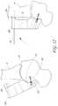
- FIG. 2shows an ankle prosthesis bone preparation system that includes a plurality of bone reference bushings and a patient specific cutting guide for an ankle procedure;
- FIG. 3is a perspective view of a reference bushing, which can be used as a bone reference in various methods disclosed and claimed herein;
- FIG. 3Ashows a cross-sectional view of the reference bushing of FIG. 3 , taken along section plane 3 A- 3 A;
- FIG. 4is a perspective view of an anterior portion of a cutting guide that has patient specific attributes
- FIG. 5is a perspective view of a posterior portion of the cutting guide of FIG. 4 ;
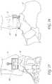
- FIG. 6illustrates a portion of a method showing the location of the reference bushings in the tibia and in the talus of a patient
- FIG. 7illustrates another portion of a method in which spatial location information in three-dimensions is acquired for a specific patient
- FIG. 8illustrates a portion of a method in which a cutting guide has been secured to a talus, the talus placed in plantar flexion;
- FIG. 9illustrates a portion of a method in which a cutting guide is preparing to contact the tibia and thereby correcting desired deformities
- FIG. 10illustrates a portion of a method in which a cutting guide is secured to the tibia and to the talus in a position to guide bone cuts to enable an implant to be properly placed, including in some embodiments automatically correcting deformity;
- FIG. 11illustrates a portion of a method in which the bone is being prepared to receive an ankle prosthesis
- FIG. 12shows a modified embodiment of an ankle prosthesis bone preparation system and a method of using the system
- FIG. 13shows a method of using the system of FIG. 12 to automatically correct deformities in an ankle joint
- FIG. 14illustrates another embodiments of a patient specific guide in which the guide comprises two separable portions
- FIG. 15shows an anterior view of an ankle prosthesis coupled with the tibia and the talus
- FIG. 16shows a lateral view of the ankle prosthesis coupled with the tibia.
- FIG. 17is an exploded view of a shoulder preparation system.
- FIG. 18shows a glenoid surface into which reference bushings have been placed.
- FIG. 19shows a later step of coupling a patient specific guide with a plurality of reference bushings in a shoulder method.
- FIG. 20is a bone preparation system with a snap-fit configuration.
- FIG. 21is a cross-sectional view of a bone preparation system.
- FIG. 22-22Ashow views of a deflectable extender facilitating a snap-fit configuration.
- FIG. 23-23Ashow a variation of a reference bushing configured to receive and couple with a bone preparation guide by way of a snap fit configuration.
- This applicationis directed to patient specific instruments, such as cutting guides, tools, and methods that can be used in joint procedures.
- the toolscan be used to place an ankle prosthesis, a shoulder or other prosthesis and, in some cases, correct deformity in a joint.
- the apparatuses and methods hereinenable the bones around a joint to be prepared with minimal incisions and relatively little to no soft tissue scraping. While small incisions may be formed for cutting bones and introducing prosthesis components, the apparatuses and methods herein allow a surgeon to avoid excessive incisions and excessive tissue removal around the bone. For instance these apparatuses and methods can enable a surgeon to not disturb or minimally disturb the periosteum, which is a dense connective tissue attached to the bone which in prior art methods is required to be mostly or completely scraped off the bone.
- FIG. 1Ashows an ankle joint 10 in a state of deformity
- FIG. 1Bshows a state in which the deformity is reduced or is not present.
- the ankle joint 10is formed between a tibia 14 , a fibula 18 , and a talus 20 .
- the state of deformity illustratedis known as varus/valgus misalignment, which a plane tangential to the superior surfaced of the talus 20 is at an angle ⁇ to a horizontal plane.
- Other forms of deformityinclude one or more of medial/lateral subluxation, anterior/posterior subluxation, subsidence and distraction.
- the misalignment of any deformitycreates discomfort and degradation of the joint. While the joint could be replaced without correcting the deformity such a replacement joint would not function properly, potentially causing pain and premature failure of the replacement joint. For this patient correcting the deformity at the same time as replacing the ankle joint will make for a more effective treatment.
- FIG. 2shows a bone preparation system 100 , which is adapted for preparing an ankle to receive an ankle prosthesis.
- the bone preparation system 100includes a first reference bushing 104 , a second reference bushing 106 , and a cutting guide 108 .
- the first reference bushing 104 and the second reference bushing 106are examples of bone references. As discussed further below, other bone references can include naturally present bony prominences, channels or openings formed in the bone or other landmarks.
- the bone preparation system 100also can include a third reference bushing 110 and a fourth reference bushing 112 .
- the first and third reference bushings 104 , 110can be placed in a first bone portion to a joint, e.g., in the tibia as shown in FIG. 7 .
- the second and fourth reference bushings 106 , 112can be placed in a second bone portion adjacent to the joint, e.g., in the talus as shown in FIG. 7 .
- the first reference bushing 104can be placed in a medial, distal and anterior aspect of the tibia 14 and the third reference bushing 110 can be placed on a lateral, distal, and anterior aspect of the tibia 14 .
- the second reference bushing 106can be placed in a medial portion of the neck of the talus 20 and the fourth reference bushing 112 can be placed in a lateral portion of the neck of the talus 20 .
- FIG. 3shows one embodiment of the reference bushing 104 .
- the reference bushing 104has a distal portion 120 and a proximal portion 122 .
- the distal portion 120extends proximally from a distal end 124 of the bushing 104 .
- the proximal portion 122extends distally from a proximal end 126 of the bushing 104 .
- the distal portion 120is adapted to be advanced into bone.
- the distal portion 120can have threads 128 to allow the bushing 104 to be threaded into the bone.
- the distal portion 120is configured to be advanced into the bone and to engage the bone by interference fit.
- the distal portion 120can include milling features 130 , including sharp edges, barbs or flutes to ease insertion of the reference bushing 104 into the bone. In another embodiment, the distal portion 120 is not threaded.
- the distal portion 120can have a flat, tapered, or other configuration suitable for direct axial advancement into the bone rather than rotation as with the reference bushing 104 .
- FIGS. 3 and 3Ashow a tool interface 138 at the proximal end 126 of the reference bushing 104 .
- the tool interface 138enables the bushing 104 to be advanced into the bone, e.g., following the threads 128 .
- the threads 128extend from the proximal end 126 to the distal end 124 of the first bushing 104 .
- the bushingcan be advanced entirely into the bone surface to be flush with the bone when so advanced.
- FIGS. 3 and 3Ashow that the reference bushing 104 can be cannulated, having a lumen 140 that extends from a proximal end 144 to a distal end 148 of the bushing 104 .
- the lumen 140can be configured to allow the reference bushing 104 to be advanced over a wire into the bone or to receive a fixation pin.
- FIG. 2shows that the bone preparation system 100 can include a fixation pin 160 to be advanced through the lumen 140 .
- two or more fixation pins 160can be provided for securing the cutting guide 108 to the talus 20 .
- two or more fixation pins 160can be provided for securing the cutting guide 108 to the tibia 14 , e.g., through the first and third reference bushings 104 , 110 .
- any of the reference bushings 104 , 106 , 110 , 112may have an internal thread rather than the smooth lumen, for attachment to a patient specific cutting guide using a mating screw rather than a pin.
- the screwcan be a separate component in some embodiments.
- an external surface of one or more of the reference features discussed belowcan be threaded and the reference features can be rotatable relative to the body of the cutting guide 108 such that the reference features can serve both a locating and a securing function.
- some of the references bushings 104 , 106 , 110 , 112have lumens that are at least partially threaded and other of the references bushings 104 , 106 , 110 , 112 can have smooth lumens without threads.
- the first reference bushing 104includes a motion limiting portion 172 configured for holding the patient specific cutting guide 108 at a selected position and/or orientation relative to the tibia 14 (or other first bone portion).
- the motion limiting portion 172can include a concave surface 176 .
- the concave surface 176is configured to receive a portion of the cutting guide 108 to hold the cutting guide relative to the ankle (or other) joint.
- the concave surface 176can be rounded, e.g., spherical, to facilitate rotating or otherwise positioning the cutting guide 108 to align apertures therein with the lumen 140 of the bushing 104 .
- each of the first reference bushing 104 , the second reference bushing 106 , the third reference bushing 110 , and the fourth reference bushing 112can have a concave surface 176 to receive a portion of and limit the motion of the cutting guide 108 .
- FIGS. 4 and 5illustrate one embodiment of the cutting guide 108 that is suited for preparing bones around the ankle joint 10 to receive an ankle prosthesis.
- the cutting guide 108is merely illustrative. Other cutting guides may be configured to engage reference bushings. Accordingly, cutting guides usable in the systems and methods claimed herein are not limited to those shown and described herein.
- the cutting guide 108can be custom made for a specific patient, as discussed further below.
- the cutting guide 108includes a first side 200 that includes a first surface 202 and a second side 204 opposite the first side 200 .
- the second side 204includes a second surface 208 .
- the first side 200 of the cutting guide 108is an anterior surface of the cutting guide when the cutting guide is used for preparing an ankle joint.
- the second side 204is a posterior surface of the cutting guide 108 in an ankle joint application.
- the cutting guide 112includes at least one cutting feature 216 that extends therethrough from the first surface 200 to the second surface 204 .
- the cutting feature 216includes a planar medial-lateral surface in the illustrated embodiment.
- a surface 203 at the bottom of the cutting guide 108 as illustrated in FIG. 4is a distal surface.
- a surface 205 at a top of the cutting guide 108 as illustrated in FIG. 4is a proximal surface.
- the cutting guide 108can include two cutting features 216 with parallel planar medial-lateral cutting surfaces. Where two cutting features 216 are provided, a first surface 216 can be disposed closer to the surface 205 than to the surface 203 while a second cutting surface 216 can be positioned between first cutting surface and the surface 203 .
- the cutting guidealso can include distal-proximal cutting features 218 .
- the cutting features 218are illustrated as an array of spaced apart openings, but could include slots or other features providing guided access to a cutting device through the cutting block 108 .
- cutting featuresneed not be parallel to one another and can be disposed at various angles with respect to one another and be disposed at various locations within the cutting block, depending on the type of implant used.
- the second side 204has a first reference feature 232 and a second reference feature 236 .
- the first reference feature 232is configured to contact the first reference bushing 104 .
- the contact between the reference feature 232 and the bushing 104can include or be augmented by placing a pin through lumens in the reference feature 232 and the bushing 104 .
- the contact between the reference feature 232 and the bushing 104can include or be augmented by a snap-fit connection between the reference feature 232 and the bushing 104 .
- the proximal portion 122could be configured to expand slightly to permit a portion of the reference feature 232 that is larger than the unexpanded size of the proximal portion 122 to be inserted into the proximal portion 122 .
- the proximal portion 122 ofcan be configured to be received in the reference feature 232 and when so received to cause expansion of the reference feature such that a snap-fit connection is formed. Further aspects of snap-fit connections are discussed below in connection with FIGS. 20-23A .
- a screw connectionis provided between one or more reference feature and bushing.
- the second reference feature 236is configured to contact the second reference bushing 108 .
- FIG. 5shows that the first and second reference features 232 , 236 can be disposed at spaced apart locations on the second side 204 of the cutting guide 108 .
- the first and second reference features 232 , 236are configured such that when the patient specific cutting guide is coupled with the first and second reference bushings 104 , 106 a clearance gap G (see FIG. 2 ) is provided between the second surface 208 and the bone or the joint beneath the cutting guide 108 .
- the gap Gcan space a portion or all of the second surface 208 , which is on the second side 204 of the cutting guide 108 facing the bone or bones, from the bone or bones around the joint being prepared for a prosthesis.
- a posterior surface of the cutting guide 108 that extends from the first reference feature 232 to the second reference feature 236does not contact the tibia or the talus 20 between the first reference bushing 104 and the second reference bushing 106 , as shown in FIG. 2 .
- the cutting guide 108is configured such that when the cutting guide 108 contacts the first and second reference bushings 104 , 106 the cutting guide 108 is spaced apart from and does not contact the tibia 14 .
- the cutting guide 108is configured such that when the cutting guide 108 contacts the first and second reference bushings 104 , 106 the cutting guide 108 is spaced apart from and does not contact the talus 20 .
- the cutting guide 108is configured such that when the cutting guide contacts the first and second reference bushings 104 , 106 the cutting guide 108 only contacts a plurality of reference bushings, e.g., any combination of two or more of the reference bushings 104 , 106 , 110 , 112 and does not contact the tibia or the talus.
- the gap Gprovides sufficient clearance to allow irregular prominences of the bone and/or underlying soft tissues to be accommodated in the space under the cutting guide 108 without requiring the surgeon to remove these structures, which provide for a much less invasive procedure.
- FIG. 5shows that the cutting guide 108 can be configured with a third reference feature 260 and a fourth reference feature 264 .
- the third reference feature 260is disposed on the second side 204 of the cutting guide.
- the third reference feature 260is disposed on a portion of the second side 204 that would be disposed over the tibia 14 when the cutting guide 108 is applied to the patient.
- the third reference feature 260is disposed opposite the first reference feature 232 .
- the first and third reference features 232 , 260can be disposed on medial and lateral sides, respectively, of the cutting guide 108 .
- the reference features 232 , 236 , 260 , 264are each configured to engage corresponding reference bushings. The engagement is such that the engagement limits motion or locks or fixes in space the location of the cutting guide relative to the specific patient's bone. This has the benefit of providing custom preparation of the bone to enable greater certainty in the position in which prosthetic components will be disposed.
- the third reference feature 260comprises a protrusion 270 that protrudes from the second surface 208 .
- the third reference feature 260includes a first end 272 fixed to the surface 208 and a second end 276 disposed away from the first end 272 of the protrusion 270 .
- the fourth reference feature 264comprises a protrusion 280 that extends from the second surface 208 .
- the fourth reference feature 264includes a first end 284 fixed to the surface 208 and a second end 288 disposed away from the first end 284 of the protrusion 280 .
- the protrusions 270 , 280are spaced apart and have a length such that when the cutting guide 108 is coupled with the third and fourth reference bushings 110 , 112 the clearance gap G is provided between the second (e.g., posterior) surface 208 and the joint (e.g., ankle) bone.
- the protrusion 270 , 280can be provided at isolated positions to provide isolated contact with corresponding reference bushings 110 , 112 or with bone references.
- the protrusions 270 , 280can be provided at discrete positions to provide spaced apart contact with corresponding reference bushings or bone references.
- the third and fourth reference features 260 , 264are described as having projections or feet.
- the first and second reference features 232 , 236also have these structures though in the illustrated embodiment these reference features are shorter. Nevertheless as shown in FIG. 2 the clearance gap G is provided between the second (posterior) side 208 of the reference guide 108 and the bones around the ankle including in the area around the first and second reference features 232 , 236 .
- FIG. 5shows that the first and third reference features 232 , 260 can be disposed on medial and lateral sides of the cutting guide 108 .
- the first and third reference features 232 , 260can be disposed at an angle to each other. The angle can be defined between lumens disposed in the reference features 232 , 260 .
- the first reference feature 232can have a first opening 290 located on the first side 202 of the guide 108 and a second opening 294 on the second side 208 of the cutting guide 108 .
- a lumenextends from the first opening 290 to the second opening 294 along an axis.
- the third reference feature 260can have a first opening 298 located on the first side 202 of the guide 108 and a second opening 302 on the second side 208 of the cutting guide 108 .
- a lumenextends from the first opening 298 to the second opening 302 along an axis.
- the lumens in the first and third reference features 232 , 260can receive the fixation pins 160 to secure the cutting guide 108 to the bone portions adjacent to the joint.
- the lumens in the first and third reference features 232 , 260can be angled to each other to help secure the orientation of the cutting guide 108 relative to the bone portions. In other embodiments these lumen may guide screws rather than pins to securely attach to reference bushing that have mating internal threads.
- FIG. 5shows that the cutting guide 108 can have four reference features.
- the second reference feature 236can have a first opening 310 located on the first side 202 of the guide 108 and a second opening 314 on the second side 208 of the cutting guide 108 .
- a lumenextends from the first opening 310 to the second opening 214 along an axis.
- the fourth reference feature 280can have a first opening 322 located on the first side 202 of the guide 108 and a second opening 326 on the second side 208 of the cutting guide 108 .
- a lumenextends from the first opening 322 to the second opening 326 along an axis.
- the second and fourth reference features 236 , 260can be disposed on medial and lateral sides respectively of the cutting guide 108 .
- the lumen of the second reference feature 236can be disposed at an angle to the lumen of the fourth reference feature 260 .
- the angle between the lumens of the second and fourth reference features 236 , 260can help to immobilize the cutting block relative to the bone portions around the ankle joint.
- these lumenmay guide screws rather than pins to securely attach to reference bushing that have mating internal threads.
- the cutting guide 108can be made for a specific patient based on spatial location information gathered from the patient, as discussed further below.
- patient specific cutting guidesare known, such devices generally require complex surface contours to allow the cutting guide to be placed directly on the bone to immobilize the cutting guides in the proper position on the bone.
- the cutting guide 108is made to provide a clearance gap G (see FIG. 10 ) between the bone and soft tissue over the ankle joint and the second side 204 , e.g., between bone and soft tissue and the second surface 208 .
- the clearance gaptakes into account the patient's soft tissue and bony structure of the joint.
- the contour or shape of the second surface 208can be relatively simple, e.g., two planar portions as discussed below. In many patients some minimal interaction with the tissue may not impact the accuracy of placement of the cutting guide as soft tissue is normally at least somewhat compressible or displaceable. In some embodiments, the gap G is sufficient to completely prevent interactions with soft tissue as well.
- the guide 108could be configured with a more complex second surface 208 to match that of the tissue surface to aid in minimizing or avoiding any tissue contact.
- reference bushings 104 , 106 , 110 , and 112can be compatible with other patient specific cutting guides or blocks, in one non-limiting example, reference bushings can be provided to matingly engage with the Prophecy® Infinity® Alignment Guide (manufactured by Wright Medical Technology, Inc, Memphis Tenn.)
- the cutting guide 108offers a simple overall construction.
- the second surface 208comprises a first portion 340 configured to be disposed in close proximity to but not in contact with a neck of a talus and a second portion 344 configured to be disposed in close proximity to but not in contact with an anterior face of a tibia.
- the first and second portions 340 , 344can have a form that is entirely independent of the shape of the tibia and talus.
- the first and second portions 340 , 344can have a relatively simple form, for example being generally planar as shown in FIG. 2 .
- the first portion 340can be disposed in a first plane and the second portion 344 can be disposed in a second plane.
- the second planecan be disposed at an angle relative to the first plane, as showing in FIG. 2 .
- the patient specific interaction of the cutting guide 108is provided by the first and second reference features 232 , 236 and by the third and fourth reference features 260 , 264 .
- the first reference feature 232 and the third reference feature 260are disposed on the first portion 340 of the second surface 208 .
- the second reference feature 236 and the fourth reference feature 264are disposed on the second portion 344 of the second surface 208 .
- the length of the reference featurese.g., the protrusions, enable the cutting guide 108 to mate with the reference bushings 104 , 106 , 110 , 112 in a prescribed manner.
- the prescribed mannerresults in the cutting feature 216 (and other cutting features of the cutting guide 108 ) being disposed at a prescribed distal-proximal location as well as at a prescribed varus-valgus angle. These and other prescribed features can be used to prepare the bones of a patient or without deformity or with deformity as discussed below.
- FIGS. 6-11illustrate various embodiments of joint surgery methods made possible by the bone preparation system 100 .
- a portion of each of the bones of the ankle jointis exposed.
- the bone portionsare exposed by forming one or more stab incisions in the skin.
- a first incision 24is made above a first bone portion, such as a distal anterior aspect of the tibia 14 .
- a second incision 28is made across a second bone portion, such as a neck of the talus 20 .
- a pathis cleared from the first incision 24 to the distal anterior aspect of the tibia 14 .
- a pathis cleared from the second incision 28 to the distal anterior aspect of the talus 20 .
- a single incisionexposes both the tibia 14 and the talus 20 .
- the first bushing 104is advanced into the tibia adjacent to the ankle joint 10 .
- the second bushing 106is advanced into the talus 20 adjacent to the ankle joint 10 .
- the first and second bushings 104 , 106can be advanced through a single incision that spans from a portion of the tibia 14 to a portion of the talus 20 .
- a cannula(not shown) is inserted through each of the incisions.
- the cannulacan be an elongate hollow tubular body with sufficient wall strength to remain open while holding the soft tissues between the skin and the bone out of the lumen of the cannula.
- the cannulacan be disposed along the axes A, B shown in FIG. 6 . More specifically, a first cannula can be placed along the axis A through the first incision 24 such that a distal end of the first cannula is adjacent to the anterior surface of the tibia 14 and a proximal end of the first cannula is outside of the skin of the patient. A second cannula can be placed along the axis B through the second incision 28 such that a distal end of the second cannula is adjacent to the neck of the talus 20 and a proximal end of the second cannula is outside of the skin of the patient.
- the reference bushing 104is advanced through the first cannula 24 .
- the second reference bushing 106is advanced through the second cannula 28 .
- FIG. 6shows a method in which the third reference bushing 110 and the fourth reference bushing 112 have also been placed in the tibia 10 and talus 20 respectively. After the four bushings 104 , 106 , 110 , 112 are placed the cannula or cannulae (if used) can be removed.
- FIG. 7shows that after the bushings have been positioned in the tibia 14 and the talus 20 , spatial location information is obtained.
- the spatial location informationcan include the location and orientation of the first reference bushing 104 and a portion of the tibia 14 around the first reference bushing 104 .
- the spatial location informationcan include the location and orientation of the second reference bushing 106 and a portion of the talus 20 around the second reference bushing 106 .
- Spatial location informationis obtained from the third reference bushing 110 if present and the tibia 14 .
- Spatial location informationis obtained from the fourth reference bushing 112 if present and the talus 20 .
- the spatial informationcan be obtained by any of a variety of methods.
- spatial location informationcan be obtained from a CT scan after one or a plurality of reference bushings are placed in the tibia 14 and the talus 20 .
- Spatial location informationcan be obtained by any three dimensional imaging or profiling technology. Spatial location information could be obtained by mechanically tracing a surface of the bone and or probing the bushings.
- the cutting guide 108is formed or created based on the spatial location information.
- spatial location information generated by a CT scanincludes a position of at least two reference bushings, e.g., two, three, or four of the bushings 104 , 106 , 110 , 112 .
- the spatial location informationis received by a system that is adapted to create or form the patient specific cutting guide 108 .
- the informationcan include spatial information about the location of at least two bone portions.
- the bone locationscan include distal and anterior surfaces of the tibia 14 , the fibula 16 , and/or the neck of the talus 20 .
- the cutting guide 108can be formed based upon the spatial location information that is received. When the cutting guide 108 is formed in this manner, the location of the cutting features 216 , 218 relative to at least one of the bone portions is established and incorporated into the structure of the cutting guide 108 . When the cutting guide 108 is mated with the reference bushings 104 , 106 , 110 , 112 the cutting features 216 , 218 are properly located to make appropriate cuts to properly position an ankle implant component.
- the ankle prosthesis procedurecan have multiple stages.
- a first stageinvolves placing the bushings 104 , 106 , 110 , 112 .
- a second stagewhich can be combined with the first stage in some cases, involves obtaining the spatial location information.
- a third stageinvolves creating the cutting guide 108 , which may be customized to the patient in view of the spatial location information.
- forming the cutting guide 108includes forming the first reference member 232 to mate with the first reference bushing 104 and forming the second reference member 236 to mate with the second reference bushing 106 .
- Forming the cutting guide 108includes forming the third reference member 260 to mate with the third reference bushing 110 and forming the fourth reference member 264 to mate with the fourth reference bushing 112 .
- the reference members 232 , 236 , 260 , 264are formed to have a length sufficient to create clearance from the bone, as discussed above, when the reference members are so mated.
- the references bushings 104 , 106 , 110 , 112will generally already be placed in the patient's bones when the fabrication of the cutting guide 108 is taking place.
- the cutting guide 108can be used on the patient in a fourth stage of a method to modify the bones around the joint to prepare the bones to be mated with a prosthesis.
- the cutting guide 108can be used on the patient for whom it was made to perform a precise prosthesis implantation procedure.
- the reference bushing 104is previously placed on a medial side of the patient's distal, anterior tibia 14 .
- the reference bushing 106is previously placed in a medial side of the neck of the talus 20 .
- the reference bushing 110is previously placed in a lateral side of the distal, anterior tibia 14 .
- the reference bushing 112is previously placed in a lateral side of the neck of the talus 20 .
- the second reference feature 236 of the cutting guide 108is connected to the reference bushing 106 .
- the connection initiallyis that a distal aspect of the second reference feature 236 is inserted into the motion limiting portion 172 of the reference bushing 106 .
- a convex surface at the free end of the second reference feature 236can be mated with the concave surface 176 .
- the mating between the reference feature 236 and the concave surface 176can include or be substituted for other sorts of contact or mating.
- a snap-fit mating, as described above and further below,could be provided between the reference feature 236 and the concave surface 176 .
- bushing 106could have a convex proximal end that receives a concave distal end portion of the reference feature 236 . More generally, any of the reference bushings can be modified to have a convex proximal portion that is received within a concave distal portion of a corresponding reference feature. In alternate embodiments, any of the reference bushings can be modified to have a male taper (e.g., a Morse taper) proximal portion.
- a male tapere.g., a Morse taper
- the male taper proximal portioncan be received within a distal portion of a corresponding reference feature (e.g., within a tapered recess, concave area, or female component).
- the matingsubsequently can be augmented by placing a pin or screw into and/or through axially aligned lumens through the reference feature 236 and the bushing 106 . Thereafter, a similar connection is provided between a convex surface of the third reference feature 260 and the motion limiting portion 172 of the reference bushing 112 .
- the matingcan subsequently be augmented by placing a pin or screw into and/or through axially aligned lumens through the reference feature 260 and the bushing 112 .
- the locations of the reference features 236 , 260 relative to the talus 20are pre-defined by the patient specific nature of the cutting guide 108 .
- the second side 208 of the cutting guide 108is spaced apart from the talus 20 at locations spaced away from the reference features 236 , 260 , for example along a path extending medially and laterally between the reference bushings 106 , 112 .
- the spacingallows the placement of the cutting guide 108 such that the soft tissues and bone need not be removed or disrupted but yet the location of the cutting feature 216 and other aspects of the cutting guide 108 relative to the talus 20 are as expected based on the spatial location information that was used to form the cutting guide 108 .
- FIG. 8shows that the connection between the cutting guide 108 and the talus 20 can be made more secure by advancing a fixation pin 160 into the opening 310 through the cutting block 108 and the reference bushing 106 and into the medial side of the neck of the talus 20 .
- the connectioncan be further more secure by advancing a fixation pin 160 into the opening 322 , through the cutting guide 108 and reference bushing 112 and into the lateral side of the neck of the talus 20 .
- a screwcould be used in place of one or both of the pins 160 .
- the pins 160may not be needed.
- Snap-fit connections and the pins 160could be used together to provide a lesser initial connection followed by a more secure connection for later phases of the procedure where greater security is needed, e.g., when a saw is disposed through the guide 108 and acting on the bone. In some cases further connection is provided by other devices such as screws 340 . In the illustrated embodiment opening 342 adjacent to the distal cutting feature 216 provide access for the screw 340 to be advanced through the cutting guide 108 and into the talus 20 .
- FIG. 8shows that in one technique the ankle 10 is placed plantar flexion to facilitate connecting the cutting guide 108 to the talus 20 . Positioning the ankle 10 in plantar flexion exposes a greater area of the neck of the talus 20 such that the cutting guide 108 can be secured to the bone. While the ankle joint is in plantar flexion, the patient specific cutting guide 108 is rigidly connected to the talus 20 with the fixation pins 160 and/or screws 340 , as discussed above.
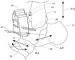
- FIG. 9shows that after the cutting guide 108 is rigidly connected to the talus 20 , motion of the talus relative to the tibia 14 and/or the fibula 16 can be provided.
- Such corrective motioncan be provided in a varus/valgus direction as indicated by the arrow R.
- Such motioncan be provided in a proximal distal direction as indicated by an arrow labeled P-D.
- Such motioncan be provided in an anterior-posterior direction as indicated by an arrow labeled A-P.
- Such motioncan be provided in a medial/lateral direction as indicated by an arrow M-L.
- FIG. 10shows that a rigid connection between the cutting guide 108 and the tibia 14 can be provided in a suitable manner, such as by advancing fixation pins 160 into the openings 290 , 298 , through the reference bushings 104 , 110 and into the tibia 14 .
- FIG. 11shows that thereafter pins 300 , reamers 304 , and saw blades 308 can be advanced through the cutting guide 108 to prepare the tibia 14 or other bone portion.
- the bushings 104 , 106 , 110 , 112can be configured to be left in place or removed.
- the methodsinvolve removing the bushings from the bone(s) around the joint after the bones have been prepared to receive a prosthesis.
- the bushings 104 , 106 , 110 , 112are small and their placement is away from the joint and sensitive soft tissue such that they may be left in place after the procedure without any impact on the patient.
- the bushings 104 , 106 , 110 , 112may be configured to be bioabsorbed into the patient and thus can be left in place but will not remain permanently in the patient.
- the reference features 232 , 236 , 260 , 264are configured to mate with bone references, in the form of passages that are formed in, e.g., drilled into, the bone(s) around the joint. As such, there is no need to remove bushings or to confirm the efficacy of permanent retention thereof in the bone. Such drilled holes can simply heal over time and thus have no permanent impact on the patient.
- FIG. 12shows an alternative embodiment in which a cutting guide 508 can be provided that includes a distal portion 512 to be mated with a neck of the talus 20 .
- the distal portioncan be mated by advancing a screw 340 therethrough.
- the screw 340can be advanced along a lumen of the cutting guide 508 defined by spatial location information of the talus 20 , e.g., of a bone reference 516 of the talus.
- the bone reference 516can be an opening formed in the talus 20 .
- the bone reference 516can be a bony prominence or a natural landmark.
- the distal portion 512has a bone engaging surface that is formed to match that of the neck of the talus 20 .
- a proximal portion 520 of the cutting guide 508can include a reference protrusion 528 .
- the reference protrusion 528can be configured to mate with a bone reference, e.g., an opening formed in the tibia 14 , a bony prominence or a natural landmark of the tibia 14 .
- a fixation pin 160can be advanced through the reference protrusion 528 to secure the cutting block 508 .
- the reference protrusion 528enables the cutting guide 508 to mate with the tibia while maintaining a clearance gap G at least in the region of the tibia. By providing the gap G, many of the advantages described herein are attained, at least as to the tibia 14 .
- FIG. 13illustrates using the cutting guide 508 to correct the deformity illustrated in FIG. 1A .
- the deformityis corrected by first coupling the distal portion 512 with the neck of the talus 20 . Thereafter a rotation described by the arrow 530 is provided. The rotation takes the cutting guide 508 from the dashed line position to the solid line position of FIG. 13 . This causes the deformity illustrated in FIG. 1A to be corrected by raising and aligning (as in FIG. 1B ) the talus 20 with the tibia 14 of the ankle joint 10 .
- FIG. 14shows a cutting guide system 608 having two separable guides, in which the proximal guide attaches individually to the proximal bone, and the distal guide attaches individually to the distal bone.
- These guidescan be formed at least partially according to the methods described herein.
- a plurality of bone referencese.g., a combination of one or more of a plurality of references bushings and a plurality of natural or surgeon formed landmarks, such as bony prominences, divots, or holes formed in the bone is provided and/or identified.
- FIG. 14shows the reference bushings 104 , 106 , 110 , 112 in dashed lines.
- a multi piece cutting guide 608is designed and manufactured that preferably is patient specific.
- the cutting guide 608includes a first block 612 configured to couple with the tibia 14 .
- the first block 612is coupled with the tibia 14 by first contacting the reference bushings 104 , 110 . Thereafter any securement method described herein can be used to rigidly connect the first block 612 to the tibia 14 .
- the cutting guide 608includes a second block 616 configured to couple with the talus 20 .
- the second block 616is coupled with the talus 20 by first contacting the reference bushings 106 , 112 . Thereafter any securement method described herein can be used to rigidly connect the second block 616 to the talus 20 .
- the first block 612has a first interface portion 620 disposed on a distal portion 624 thereof.
- the distal portion 624can be on a distal face or can be on an anterior face, e.g., extending proximally from a distal face of the first block 612 .
- the first interface portion 620can also include one or a plurality of apertures 628 formed in the distal portion 624 .
- the second block 616can have a second interface portion 632 disposed on a proximal portion 636 .
- the proximal portion 636can be on a proximal face or can be on an anterior face, e.g., extending distally from a proximal distal face of the second block 616 .
- the second interface portion 632can also include one or a plurality of apertures 640 formed in the proximal portion 636 .
- the first and second interface portions 620 , 632are configured to mate to provide a spatial position of the tibia 14 and the talus 20 .
- the first and second blocks 612 , 616can be configured such that when the interface portions 620 , 632 are mated cutting features, which are similar to any of the described above and which are formed on and through the cutting guide 608 , are properly positioned and oriented.
- the first interface portion 620comprises a concave recess that is open on a distal face of the first block 612 . The recess extends only partly through the thickness of the first block 612 from the anterior face thereof.
- the second interface portion 632includes a proximally extending protrusion on the second block 616 that is configured to be received in the concave recess of the first block 612 .
- the first and second blocks 612 , 616can be secured together by any suitable means, such as by advancing pins through the apertures 640 and into the apertures 628 .
- the first block 612can have reference features similar to the reference features 232 , 260 .
- the second block 616can have reference features similar to the reference features 236 , 264 .
- the first block 612is shown with fixation pins 160 extending into openings similar to the openings 290 , 298 .
- the second block 616is shown with fasteners 350 securing the second block 616 to the talus. Accordingly, the second block 616 can be configured to be positioned on the talus 20 in a variety of ways.
- the fasteners 350can be advanced through reference bushings or similar features to secure the second block 616 in a predefined position relative to the talus 20 and/or the ankle 10 .
- the second block 616could have openings similar to the openings 310 , 322 for advancement of fixation pins 160 through the second block 616 and through a bone reference, such as the reference bushings 106 , 112 .
- a bone referencesuch as the reference bushings 106 , 112 .
- first and second blocks 612 , 616are secured to the tibia 14 and talus 20 respectively, relative motion is provided between the talus 20 or foot and the tibia 14 or lower leg. Such movement continues until the second interface portion 632 is engaged with, e.g., is received in, the first interface portion 620 . Thereafter, the portions 620 , 632 are secured together. For example, a pin can be advanced through the openings 640 and into the opening 628 . When the first and second blocks 612 , 616 are so engaged, the talus 20 will be properly positioned relative to the tibia 14 . The proper positioning of the first and second blocks 612 , 616 can result in a correction of any deformity in the ankle. For example, when so engaged, the varus/valgus deformity of FIG. 1A will be reduced or eliminated as shown in FIG. 1B .
- FIGS. 15 and 16show that after using any of the cutting guides herein to prepare an ankle joint, a prosthesis 550 can be placed in the joint space.
- the prosthesis 550can include a proximal portion 554 coupled with the talus 20 and a distal portion 558 coupled with the tibia 14 .
- the proximal and distal portions 554 , 558articulate over each other to restore normal and pain free function to the ankle joint 10 .
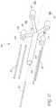
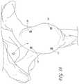
- FIGS. 17-19show an example.
- a system 1000is provided that includes the reference bushings 104 , 106 , 110 , 112 , a guide 1008 , and a central pin 1012 .
- the guide 1008is configured to guide the placement of the central pin 1012 in a central region of the glenoid G.
- the guide 1008has a plurality of arms 1016 , e.g., four arms, that extend from a central hub 1020 .
- the hub 1020has a lumen 1024 extending therethrough to guide the central pin 1012 along an axis defined through the hub 1020 in the center of the lumen 1024 .
- the arms 1016 and other parts of the guide 1008are formed based on information gathered from the patient, e.g., using an imaging device as discussed above.
- the arms 1016each can have a pin guide 1032 disposed at a location away from the central hub 1020 .
- the pin guides 1032can be hubs or cylindrical bodies.
- the pin guides 1032can each have a lumen 1036 therethrough for guiding one of the pins 160 into the glenoid G as discussed below.
- Each of the guides 1032can be formed to mate with the proximal portion 122 of one of the reference bushing 104 , 106 , 110 , 112 .
- each of the pin guides 1032can have a convex end portion that can be received in the proximal portion 122 and interface with the concave surface 176 .
- FIG. 18shows the reference bushings placed in the articular surface of the glenoid G. In many procedures, this surface is subsequently reamed and may be covered by a low frication artificial articular surface. However, the procedure could be modified to place the bushings 104 , 106 , 110 , 112 in the scapula outside the articular area of the glenoid G.
- FIG. 19shows the guide 1008 being advanced medially up against the bushings 104 , 106 , 110 , 112 .
- the pins 160can be advanced into the lumens 1036 to secure the guide 1008 in place.
- the central pin 1012can be advanced into the glenoid G and into a central glenoid channel GC.
- the formation of the glenoid channel GCcan be performed through the lumen 1024 . Because the guide 1008 is formed with reference to the specific anatomy of the patient the location and the orientation of the glenoid channel GC can be specified by the form of the guide 1008 and the placement of the bushing 104 , 106 , 110 , 112 . This can help to more precisely guide other aspects of the procedure such as the trajectory of a reamer, the formation of peripheral holes for anchoring a glenoid component.
- the humeruswill generally also be modified.
- the proximal humeruscan be resected and a ball portion can be secured to the humerus to form an anatomic configuration.
- the proximal portioncan be resected and a concave member can be supported in the resected humerus by a humeral anchor.
- a humeral anchorcan be used to support these procedures.
- one or more of the reference bushings 104 , 106 , 110 , 112can be placed in a side portion of the humerus near the proximal end thereof.
- the bushings 104 , 106 , 110 , 112can be used to support a cutting block for resecting the humerus at a position and angle that is specific to the patient and is dictated by the placement of the bushings 104 , 106 , 110 , 112 and the configuration of the cutting block. Also, later aspects of the humeral procedure could also be guided in the methods discussed above.
- the bushings 104 , 106 , 110 , 112could be embedded in the resected face of the humerus. Thereafter, a guide similar to the guide 1008 could be used to place a central pin similar to the pin 1012 that could guide further reaming or cutting of the proximal humerus. The central pin could also or alternatively be used to advance a humeral anchor into the proximal humus.
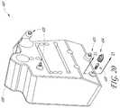
- FIGS. 20-23Aillustrate a bone system 400 that employs a snap-fit connection between components thereof.
- the system 400is similar to the system 100 except as described differently below.
- the system 400includes a cutting guide 408 , a plurality of deflectable extenders 420 and one or more reference bushings 404 . Although one reference bushing 404 is illustrated, the system 400 can have four reference bushings as in the system 100 .
- FIG. 20shows the cutting guide 408 and one of each of the deflectable extenders 420 and the reference bushings 404 in an exploded configuration.
- the exploded configurationis provided to better illustrate the components but also shows that in certain embodiments, these components are separate or can be separated in use.
- the separable configurationallows the user to assemble at least some of the parts at the operating table or in pre-operative activities.
- the separability of the componentsalso allows at least some of the components to be reused.
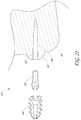
- FIG. 21shows components of the system 400 in cross-section illustrating more features of the system 400 .
- a portion of the cutting guide 408is shown in cross-section.
- the cutting guide 408has a lumen 434 that extends through the body of the cutting guide.
- a portion of the lumen 434 that is closest to the patient when applied to the patientopens into a patient-facing aperture 438 .
- a threaded portion 442 of the lumen 434is provided from the aperture 438 in a direction away from the aperture into the body of the cutting guide 408 .
- the cutting guide 408also includes a protrusion 446 that extends away from a patient-facing side of the cutting guide 408 .
- the protrusion 446helps to create clearance, e.g., the gap G discussed above and shown in connection with the system 100 in FIG. 10 , between the guide 408 and the tissues of the patient when applied.
- the protrusion 446could be smaller or eliminated in some embodiments, for example if the deflectable extenders 420 were elongated sufficiently to provide the gap G.
- the threaded portion 442can be disposed primarily or even exclusively in the protrusion 446 . In the illustrated embodiment, the threaded portion 442 also extends into the body of the cutting guide 408 .
- FIGS. 21 and 23-23Ashow the deflectable extender 420 in greater detail.
- the deflectable extender 420can have a proximal portion 450 and a distal portion 454 .
- the proximal portion 450has threads 458 .
- the threads 458are configured to engage the threaded portion 442 of the lumen 434 .
- the threads 458 and the threaded portion 442provide an intuitive, secure connection between the extenders 420 and the cutting guide 408 other structures for such connection could be provided. For example, a bayonet connection or detents could be provided.
- the distal portion 454 of the deflectable extender 420includes a deflectable portion 466 .
- the deflectable portion 466enables the distal portion 454 to be received in the reference bushing 404 as discussed further below.
- the distal portion 454 of the deflectable extender 420has a tapered outer profile 470 .
- the tapered profile 470can have a generally oval cross-section.
- the tapered profileincludes two curved surfaces. One curved surface is disposed on a first projection 474 and another curved surfaced is disposed on a second projection 478 .
- the first and second projections 474 , 478can be separated by a gap 482 .
- the gap 482permits some movement of the projections 474 , 478 toward and away from a longitudinal axis 486 of the deflectable extender 420 . As discussed further below, the movement of the projections 474 , 478 into the gap 482 permits the distal portion 454 to be inserted into and thereafter firmly engage the reference bushing 404 as discussed further below.
- the gap 482provides for insertion of the deflectable extender 420 into the reference bushing 404
- the extender 420could have a detent arrangement or could be compressible such that the extender 420 can be inserted into the reference bushing 404 .
- the deflectable extender 420includes a shoulder 480 between the threads 458 and the projections 474 , 478 .
- the shoulder 480provides clearly demarked stop position for the deflectable extender relative to the cutting guide 408 .
- the shoulder 480allows the surgeon to quickly and accurately advance the deflectable extender 420 to precisely the correct position. This is important in that it helps to maintain the extent of the gap G, which preferably is large enough to allow the tissue beneath the guides to not be disturbed as discussed elsewhere herein.
- FIGS. 21-22Ashow details of the reference bushing 404 .
- the reference bushing 404can be similar to the reference bushing 104 except as described differently below.
- the reference bushing 404includes a proximal portion 490 that is configured to receive and retain the distal portion 454 of the deflectable extender 420 .
- the interior surface of the proximal portion 490can have a surface 494 with an oval curvature, or any curvature that matches the outer tapered profile of the projections 474 , 478 .
- the reference bushing 404has a constriction 502 between a proximal end of the reference bushing 404 and a distal end of the surface 494 .
- a flared surface 506extends from the constriction 502 to the proximal end of the reference bushing 404 .
- the constriction 502can be positioned to be received in a reduced diameter section of the deflectable extender 420 (see FIGS. 23 and 23A ). More broadly, the reference bushing 404 and the deflectable extender 420 are configured to have the same shape in cross-section so that a close fit is provided when these components are joined together.
- the use of the system 400is similar to the use of the system 100 , except as described differently below.
- the guide 408is prepared using patient specific data that can be gathered by any modality, including imaging or mechanical tracing.
- the reference bushing 404 and any additional reference bushingsare implanted as described above in prescribed locations.
- the deflectable extenders 420are coupled with the guide 408 .
- the deflectable extendersare integrated into the guide 408 , e.g., pre-assembled or formed as a monolithic structure or of continuous material. Thereafter, the guide 408 and the deflectable extenders 420 are placed on the reference bushings. A distal portion of the profile 474 is placed into the flared surface 506 and rested there.
- FIG. 21shows that there is no lumen through the extenders 420 in some embodiments. This is because the snap connection provided between the extenders 420 and the reference bushings 404 (and the other bushings that may be present) is strong enough that the guide 408 need not be secured with separate pins.
- the extenders 420 and the guide 408each have lumens that facilitate placing pins through the cutting guide 408 , the extenders 20 and the bushing 404 (and the other bushings that may be present).
- the embodiments provided hereinprovide the additional advantage of allowing for less disruption of the soft tissue and bone around the joint.
- the soft tissuesdo not have to be completely cleared away from the bone surface to mate a patient specific surface with the exposed bone.
- a minimal skin incisionmay be made to only accommodate the insertion of cutting tools and implant, and the periosteum does not need to be scrapped from the bone.
- the reference featurescan be advanced into contact with discrete, isolated bone references (e.g., reference bushings) while allowing the clearance gap G to be dispose therebetween.
- the gap Gcan accommodate soft tissue or can just allow the cutting block not to impinge on the soft tissue or bone therebeneath.
Landscapes
- Health & Medical Sciences (AREA)
- Surgery (AREA)
- Life Sciences & Earth Sciences (AREA)
- Engineering & Computer Science (AREA)
- Biomedical Technology (AREA)
- Public Health (AREA)
- Veterinary Medicine (AREA)
- Nuclear Medicine, Radiotherapy & Molecular Imaging (AREA)
- General Health & Medical Sciences (AREA)
- Heart & Thoracic Surgery (AREA)
- Medical Informatics (AREA)
- Molecular Biology (AREA)
- Animal Behavior & Ethology (AREA)
- Dentistry (AREA)
- Oral & Maxillofacial Surgery (AREA)
- Orthopedic Medicine & Surgery (AREA)
- Robotics (AREA)
- Prostheses (AREA)
- Surgical Instruments (AREA)
Abstract
Description
Claims (11)
Priority Applications (3)
| Application Number | Priority Date | Filing Date | Title |
|---|---|---|---|
| US16/008,471US11065016B2 (en) | 2015-12-16 | 2018-06-14 | Patient specific instruments and methods for joint prosthesis |
| US17/348,993US11980377B2 (en) | 2015-12-16 | 2021-06-16 | Patient specific instruments and methods for joint prosthesis |
| US18/632,685US20240252187A1 (en) | 2015-12-16 | 2024-04-11 | Patient specific instruments and methods for joint prosthesis |
Applications Claiming Priority (3)
| Application Number | Priority Date | Filing Date | Title |
|---|---|---|---|
| US201562268045P | 2015-12-16 | 2015-12-16 | |
| PCT/US2016/063883WO2017105815A1 (en) | 2015-12-16 | 2016-11-28 | Patient specific instruments and methods for joint prosthesis |
| US16/008,471US11065016B2 (en) | 2015-12-16 | 2018-06-14 | Patient specific instruments and methods for joint prosthesis |
Related Parent Applications (1)
| Application Number | Title | Priority Date | Filing Date |
|---|---|---|---|
| PCT/US2016/063883ContinuationWO2017105815A1 (en) | 2015-12-16 | 2016-11-28 | Patient specific instruments and methods for joint prosthesis |
Related Child Applications (1)
| Application Number | Title | Priority Date | Filing Date |
|---|---|---|---|
| US17/348,993ContinuationUS11980377B2 (en) | 2015-12-16 | 2021-06-16 | Patient specific instruments and methods for joint prosthesis |
Publications (2)
| Publication Number | Publication Date |
|---|---|
| US20180289380A1 US20180289380A1 (en) | 2018-10-11 |
| US11065016B2true US11065016B2 (en) | 2021-07-20 |
Family
ID=57708726
Family Applications (3)
| Application Number | Title | Priority Date | Filing Date |
|---|---|---|---|
| US16/008,471Active2037-09-02US11065016B2 (en) | 2015-12-16 | 2018-06-14 | Patient specific instruments and methods for joint prosthesis |
| US17/348,993Active2037-09-28US11980377B2 (en) | 2015-12-16 | 2021-06-16 | Patient specific instruments and methods for joint prosthesis |
| US18/632,685PendingUS20240252187A1 (en) | 2015-12-16 | 2024-04-11 | Patient specific instruments and methods for joint prosthesis |
Family Applications After (2)
| Application Number | Title | Priority Date | Filing Date |
|---|---|---|---|
| US17/348,993Active2037-09-28US11980377B2 (en) | 2015-12-16 | 2021-06-16 | Patient specific instruments and methods for joint prosthesis |
| US18/632,685PendingUS20240252187A1 (en) | 2015-12-16 | 2024-04-11 | Patient specific instruments and methods for joint prosthesis |
Country Status (5)
| Country | Link |
|---|---|
| US (3) | US11065016B2 (en) |
| EP (1) | EP3389513A1 (en) |
| AU (2) | AU2016371425B2 (en) |
| CA (1) | CA3007082A1 (en) |
| WO (1) | WO2017105815A1 (en) |
Cited By (1)
| Publication number | Priority date | Publication date | Assignee | Title |
|---|---|---|---|---|
| US20210315593A1 (en)* | 2015-12-16 | 2021-10-14 | Howmedica Osteonics Corp. | Patient specific instruments and methods for joint prosthesis |
Families Citing this family (28)
| Publication number | Priority date | Publication date | Assignee | Title |
|---|---|---|---|---|
| FR2932674B1 (en) | 2008-06-20 | 2011-11-18 | Tornier Sa | METHOD FOR MODELING A GLENOIDAL SURFACE OF AN OMOPLATE, DEVICE FOR IMPLANTING A GLENOIDAL COMPONENT OF A SHOULDER PROSTHESIS, AND METHOD FOR MANUFACTURING SUCH COMPOUND |
| US10405993B2 (en) | 2013-11-13 | 2019-09-10 | Tornier Sas | Shoulder patient specific instrument |
| US11033333B2 (en) | 2017-04-06 | 2021-06-15 | Stryker European Holdings I, Llc | Plate selection user interface and design tool with database |
| EP3424452B1 (en) | 2017-06-16 | 2024-03-13 | Stryker European Operations Holdings LLC | Patient-specific bridging plates |
| EP3651664A1 (en) | 2017-07-11 | 2020-05-20 | Tornier, Inc. | Guides and instruments for improving accuracy of glenoid implant placement |
| US10959742B2 (en) | 2017-07-11 | 2021-03-30 | Tornier, Inc. | Patient specific humeral cutting guides |
| CA3087066A1 (en) | 2017-12-29 | 2019-07-04 | Tornier, Inc. | Patient specific humeral implant components |
| US10849665B2 (en)* | 2018-10-29 | 2020-12-01 | Stryker European Operations Holdings Llc | Snap-fit cutting guides and plating systems |
| US12295628B2 (en) | 2018-11-01 | 2025-05-13 | Howmedica Osteonics Corp. | Device for fixating orthopedic injury |
| EP3893772A4 (en) | 2018-12-13 | 2022-11-23 | Paragon 28, Inc. | RESECTION GUIDES, SCAN REAMERS AND METHODS FOR USE IN TOTAL ANKLE REPLACEMENT |
| EP3893765A4 (en) | 2018-12-13 | 2023-03-29 | Paragon 28, Inc. | Total ankle replacement surgical method |
| WO2020124052A1 (en)* | 2018-12-13 | 2020-06-18 | Paragon 28, Inc. | Instruments, guides and related methods for total ankle replacement |
| EP4027922A4 (en) | 2019-09-13 | 2023-10-04 | MIOS Marketing LLC, DBA RedPoint Medical 3D | Patient-specific surgical methods and instrumentation |
| US20220211387A1 (en)* | 2019-09-13 | 2022-07-07 | Inmotus Medical Llc | Patient-specific surgical methods and instrumentation |
| US11986251B2 (en) | 2019-09-13 | 2024-05-21 | Treace Medical Concepts, Inc. | Patient-specific osteotomy instrumentation |
| EP4044940A4 (en) | 2019-10-18 | 2023-11-01 | Orthosoft ULC | PATIENT-SPECIFIC INSTRUMENTS AND PROCEDURES FOR ARTHROPLASTY OF THE ANKLE JOINT |
| USD920515S1 (en) | 2020-01-08 | 2021-05-25 | Restor3D, Inc. | Spinal implant |
| USD920516S1 (en) | 2020-01-08 | 2021-05-25 | Restor3D, Inc. | Osteotomy wedge |
| USD920517S1 (en) | 2020-01-08 | 2021-05-25 | Restor3D, Inc. | Osteotomy wedge |
| US12349926B2 (en)* | 2020-03-11 | 2025-07-08 | Stryker European Operations Limited | Patient-specific ankle guide systems and methods |
| US12350160B2 (en) | 2021-06-08 | 2025-07-08 | Wright Medical Technology, Inc. | Modular implant with external fixation |
| US11324525B1 (en)* | 2021-06-30 | 2022-05-10 | Kinos Medical Inc. | Surgical alignment guide assembly for total ankle replacement and method of using the same |
| WO2024059868A2 (en)* | 2022-09-16 | 2024-03-21 | Board Of Supervisors Of Louisiana State University And Agricultural And Mechanical College | Surgical screw aligner and methods of use thereof |
| US11806028B1 (en) | 2022-10-04 | 2023-11-07 | Restor3D, Inc. | Surgical guides and processes for producing and using the same |
| USD1051384S1 (en) | 2023-03-24 | 2024-11-12 | Restor3D, Inc. | Bone fixation pin |
| USD1053353S1 (en) | 2023-03-24 | 2024-12-03 | Restor3D, Inc. | Orthopedic screw |
| USD1052732S1 (en) | 2023-05-25 | 2024-11-26 | Restor3D, Inc. | Subtalar wedge |
| US11960266B1 (en) | 2023-08-23 | 2024-04-16 | Restor3D, Inc. | Patient-specific medical devices and additive manufacturing processes for producing the same |
Citations (253)
| Publication number | Priority date | Publication date | Assignee | Title |
|---|---|---|---|---|
| FR2579454A1 (en) | 1985-03-28 | 1986-10-03 | Rambert Andre | Glenohumeral prosthesis |
| US4919670A (en) | 1988-02-03 | 1990-04-24 | Intermedics Orthopedics, Inc. | Modular humeral prosthesis |
| US5030219A (en) | 1990-01-22 | 1991-07-09 | Boehringer Mannheim Corporation | Glenoid component installation tools |
| WO1993025157A1 (en) | 1992-06-18 | 1993-12-23 | Klaus Radermacher | Template for treatment tools and method for the treatment of osseous structures |
| US5329846A (en) | 1991-08-12 | 1994-07-19 | Bonutti Peter M | Tissue press and system |
| US5383938A (en) | 1993-02-12 | 1995-01-24 | Zimmer, Inc. | Locking ring for an acetabular cup |
| US5458637A (en) | 1994-11-21 | 1995-10-17 | Zimmer, Inc. | Orthopaedic base component with modular augmentation block |
| US5531793A (en) | 1992-09-28 | 1996-07-02 | Depuy Inc. | Orthopedic implant augmentation and stabilization device |
| US5610966A (en) | 1995-02-15 | 1997-03-11 | Argonne National Laboratories/University Of Chicago Development Corp. | Method and device for linear wear analysis |
| US5725586A (en) | 1995-09-29 | 1998-03-10 | Johnson & Johnson Professional, Inc. | Hollow bone prosthesis with tailored flexibility |
| US5768134A (en) | 1994-04-19 | 1998-06-16 | Materialise, Naamloze Vennootschap | Method for making a perfected medical model on the basis of digital image information of a part of the body |
| US5769856A (en) | 1996-06-24 | 1998-06-23 | Osteonics Corp. | Drill guide and implant method |
| US5779710A (en) | 1996-06-21 | 1998-07-14 | Matsen, Iii; Frederick A. | Joint replacement method and apparatus |
| US5807437A (en) | 1989-12-08 | 1998-09-15 | Massachusetts Institute Of Technology | Three dimensional printing system |
| US5824078A (en) | 1996-03-11 | 1998-10-20 | The Board Of Trustees Of The University Of Arkansas | Composite allograft, press, and methods |
| US5824085A (en) | 1996-09-30 | 1998-10-20 | Integrated Surgical Systems, Inc. | System and method for cavity generation for surgical planning and initial placement of a bone prosthesis |
| US6002859A (en) | 1997-02-21 | 1999-12-14 | Carnegie Mellon University | Apparatus and method facilitating the implantation of artificial components in joints |
| WO2000035346A2 (en) | 1998-09-14 | 2000-06-22 | Stanford University | Assessing the condition of a joint and preventing damage |
| US6129764A (en) | 1998-11-24 | 2000-10-10 | Stryker Technologies Corporation | Modular prosthetic joint components |
| WO2000059411A1 (en) | 1999-04-02 | 2000-10-12 | Fell Barry M | Surgically implantable knee prosthesis |
| US6172856B1 (en) | 1997-12-30 | 2001-01-09 | Samsung Electronics Co., Ltd. | Magnetic head transferring device with improved magnetic head unlocking for hard disk drives |
| US6183519B1 (en) | 1997-03-10 | 2001-02-06 | Tornier Sa | Ankle prosthesis |
| US20010047210A1 (en) | 2000-03-16 | 2001-11-29 | Wolf Eugene M. | Facile total shoulder arthroplasty apparatus and method |
| US20020007294A1 (en) | 2000-04-05 | 2002-01-17 | Bradbury Thomas J. | System and method for rapidly customizing a design and remotely manufacturing biomedical devices using a computer system |
| US20020025358A1 (en) | 1996-03-11 | 2002-02-28 | Carl Nelson | Composite allograft press |
| US6364910B1 (en) | 2001-07-11 | 2002-04-02 | Biomet, Inc. | Method and apparatus for use of a glenoid component |
| US6385475B1 (en) | 1997-03-11 | 2002-05-07 | Philippe Cinquin | Process and device for the preoperative determination of the positioning data of endoprosthetic parts |
| US20020082741A1 (en) | 2000-07-27 | 2002-06-27 | Jyoti Mazumder | Fabrication of biomedical implants using direct metal deposition |
| WO2002061688A2 (en) | 2001-01-29 | 2002-08-08 | The Acrobot Company Limited | Modelling for surgery |
| US6432142B1 (en) | 1999-07-26 | 2002-08-13 | Japan As Represented By Secretary Of Agency Of Industrial Science And Technology | Mold for uniform pressing of substrate side faces, and artificial bone of titanium alloy having high biological affinity |
| US6459948B1 (en) | 1996-07-03 | 2002-10-01 | The Trustees Of Columbia University In The City Of New York | Anatomically correct prosthesis and method and apparatus for manufacturing prosthesis |
| EP1265555A2 (en) | 2000-03-22 | 2002-12-18 | Synthes (U.S.A.) | Plugs for filling bony defects |
| US20030139818A1 (en) | 2002-01-18 | 2003-07-24 | Rogers James R. | Adjustable long bone prosthesis |
| US6648894B2 (en) | 2000-12-21 | 2003-11-18 | Stryker Spine | Bone graft forming guide and method of forming bone grafts |
| US20040064189A1 (en) | 2002-09-27 | 2004-04-01 | Maroney Brian John | Concave resurfacing prosthesis |
| US20040133276A1 (en) | 2002-10-07 | 2004-07-08 | Imaging Therapeutics, Inc. | Minimally invasive joint implant with 3-Dimensional geometry matching the articular surfaces |
| US6772026B2 (en) | 2000-04-05 | 2004-08-03 | Therics, Inc. | System and method for rapidly customizing design, manufacture and/or selection of biomedical devices |
| US20040171924A1 (en) | 2003-01-30 | 2004-09-02 | Mire David A. | Method and apparatus for preplanning a surgical procedure |
| US6797006B2 (en) | 2002-06-18 | 2004-09-28 | Zimmer Technology, Inc. | Porous unicondylar knee |
| US6849223B2 (en) | 2001-04-19 | 2005-02-01 | Case Western Reserve University | Fabrication of a polymeric prosthetic implant |
| US20050049709A1 (en) | 2003-08-25 | 2005-03-03 | Alain Tornier | Glenoid component of a shoulder prosthesis and complete shoulder prosthesis incorporating such a component |
| US20050065628A1 (en) | 2003-09-18 | 2005-03-24 | Jeffrey Roose | Customized prosthesis and method of designing and manufacturing a customized prosthesis by utilizing computed tomography data |
| US20050065617A1 (en) | 2003-09-05 | 2005-03-24 | Moctezuma De La Barrera Jose Luis | System and method of performing ball and socket joint arthroscopy |
| US20050112397A1 (en) | 2003-07-24 | 2005-05-26 | Rolfe Jonathan L. | Assembled non-random foams |
| EP1563810A1 (en) | 2004-02-10 | 2005-08-17 | Tornier | Surgical apparatus for implanting a total hip prosthesis |
| US20050197814A1 (en) | 2004-03-05 | 2005-09-08 | Aram Luke J. | System and method for designing a physiometric implant system |
| US20050216305A1 (en) | 2002-02-08 | 2005-09-29 | Are Funderud | System for preparation and transmission of specification for customized prostheses |
| US20060100714A1 (en) | 2003-04-02 | 2006-05-11 | Ortho Development Corporation | Tibial augment connector |
| US20060136058A1 (en) | 2004-12-17 | 2006-06-22 | William Pietrzak | Patient specific anatomically correct implants to repair or replace hard or soft tissue |
| US7175665B2 (en) | 2002-09-09 | 2007-02-13 | Depuy Products, Inc. | Universal tibial augment |
| US20070089518A1 (en) | 2005-10-26 | 2007-04-26 | Ericson Milton N | Method and apparatus for orthopedic implant assessment |
| US20070118055A1 (en) | 2005-11-04 | 2007-05-24 | Smith & Nephew, Inc. | Systems and methods for facilitating surgical procedures involving custom medical implants |
| US20070118243A1 (en) | 2005-10-14 | 2007-05-24 | Vantus Technology Corporation | Personal fit medical implants and orthopedic surgical instruments and methods for making |
| US20070191741A1 (en) | 2006-02-15 | 2007-08-16 | Chung Yuan Christian University | Image analysis methods for gleno-humeral joint morphology |
| US20070244563A1 (en) | 2006-03-23 | 2007-10-18 | Roche Chistopher P | Reverse shoulder prosthesis |
| US20070249967A1 (en) | 2006-03-21 | 2007-10-25 | Perception Raisonnement Action En Medecine | Computer-aided osteoplasty surgery system |
| EP1862151A1 (en) | 2006-05-31 | 2007-12-05 | BrainLAB AG | Method for selection of an femoral implant |
| US20080014082A1 (en) | 2006-07-12 | 2008-01-17 | Katsutoshi Kobayashi | Multi Stage Diffuser Pump |
| EP1902689A1 (en) | 2006-09-20 | 2008-03-26 | DePuy Products, Inc. | Glenoid component for shoulder arthroplasty |
| DE102006047663A1 (en) | 2006-09-29 | 2008-04-03 | Aesculap Ag & Co. Kg | Augmentation component for bone implant is constructed on bone implant from connected bridges that form cavities between them of dimensions between 0.5 and 6 mm |
| US20080183297A1 (en) | 2007-01-30 | 2008-07-31 | Tornier | Method and apparatus for fitting a shoulder prosthesis |
| US20080228269A1 (en) | 2005-05-11 | 2008-09-18 | Fondel Finance B.V. | Moulded article and mass and method for production thereof |
| US20080243127A1 (en) | 2001-05-25 | 2008-10-02 | Conformis, Inc. | Surgical Tools for Arthroplasty |
| US7468075B2 (en) | 2001-05-25 | 2008-12-23 | Conformis, Inc. | Methods and compositions for articular repair |
| US7469474B2 (en) | 2002-01-17 | 2008-12-30 | Depuy International Limited | Manufacturing a component with a near spherical surface |
| US7534263B2 (en) | 2001-05-25 | 2009-05-19 | Conformis, Inc. | Surgical tools facilitating increased accuracy, speed and simplicity in performing joint arthroplasty |
| US20090204225A1 (en) | 2008-02-12 | 2009-08-13 | Biomet Manufacturing Corp. | Acetabular Cup Having An Adjustable Modular Augment |
| US20090226068A1 (en) | 2008-03-05 | 2009-09-10 | Conformis, Inc. | Implants for Altering Wear Patterns of Articular Surfaces |
| US7599539B2 (en) | 2006-07-28 | 2009-10-06 | Varian Medical Systems International Ag | Anatomic orientation in medical images |
| US20090264894A1 (en) | 2008-04-21 | 2009-10-22 | Ray Wasielewski | Method of designing orthopedic implants using in vivo data |
| US7618451B2 (en) | 2001-05-25 | 2009-11-17 | Conformis, Inc. | Patient selectable joint arthroplasty devices and surgical tools facilitating increased accuracy, speed and simplicity in performing total and partial joint arthroplasty |
| US20090292464A1 (en) | 2008-05-23 | 2009-11-26 | Tele Atlas North America, Inc. | System and method for providing geographic markers on electronic objects and real-world objects |
| US7634119B2 (en) | 2002-12-04 | 2009-12-15 | Conformis, Inc. | Fusion of multiple imaging planes for isotropic imaging in MRI and quantitative image analysis using isotropic or near-isotropic imaging |
| EP2135576A1 (en) | 2008-06-20 | 2009-12-23 | Tornier | Method for modelling a glenoidal surface of a scapula, device for implanting a glenoidal component of a shoulder prosthesis, and method for manufacturing such a component |
| US7648530B2 (en) | 2004-01-22 | 2010-01-19 | Sq Products Ag | Humeral head prosthesis |
| US7702380B1 (en) | 1999-11-03 | 2010-04-20 | Case Western Reserve University | System and method for producing a three-dimensional model |
| EP1917051B1 (en) | 2005-08-06 | 2010-06-23 | M.Pore Gmbh | Spongy metallic implant and method for the production thereof |
| US20100161066A1 (en) | 2008-12-23 | 2010-06-24 | Depuy Products, Inc. | Shoulder Prosthesis having Augmented Metaglene Component for Use in Rotator Cuff Deficient Shoulder |
| US7747305B2 (en) | 2003-06-11 | 2010-06-29 | Case Western Reserve University | Computer-aided-design of skeletal implants |
| US20100191100A1 (en) | 2009-01-23 | 2010-07-29 | Warsaw Orthopedic, Inc. | Methods and systems for diagnosing, treating, or tracking spinal disorders |
| US20100217270A1 (en) | 2009-02-25 | 2010-08-26 | Conformis, Inc. | Integrated Production of Patient-Specific Implants and Instrumentation |
| US7796791B2 (en) | 2002-11-07 | 2010-09-14 | Conformis, Inc. | Methods for determining meniscal size and shape and for devising treatment |
| US7802503B2 (en) | 2006-07-14 | 2010-09-28 | Couvillion Roy J | Method and apparatus for preparing bone grafts, including grafts for lumbar/thoracic interbody fusion |
| WO2010120346A1 (en) | 2009-04-13 | 2010-10-21 | George John Lian | Custom radiographically designed cutting guides and instruments for use in total ankle replacement surgery |
| EP2243445A2 (en) | 2006-02-23 | 2010-10-27 | DePuy (Ireland) | A glenoid component of a shoulder joint prosthesis |
| US20100303313A1 (en) | 2001-05-25 | 2010-12-02 | Conformis, Inc. | Methods and Compositions for Articular Repair |
| US20110029088A1 (en) | 2009-07-31 | 2011-02-03 | Zimmer, Gmbh | Glenoid alignment tool |
| US20110040334A1 (en) | 2001-07-12 | 2011-02-17 | Kaes David R | Intervertebral implant with movement resistant structure |
| US7892287B2 (en) | 2004-09-27 | 2011-02-22 | Depuy Products, Inc. | Glenoid augment and associated method |
| US20110046735A1 (en) | 2006-02-27 | 2011-02-24 | Biomet Manufacturing Corp. | Patient-Specific Implants |
| US20110054478A1 (en) | 2006-02-27 | 2011-03-03 | Biomet Manufacturing Corp. | Patient-Specific Shoulder Guide |
| EP2324801A1 (en) | 2009-11-24 | 2011-05-25 | Tornier | Device and method for determining a configuration for implanting a glenoid prosthetic component or a configuration for applying a glenoid resurfacing tool |
| US20110144760A1 (en) | 2004-01-05 | 2011-06-16 | Conformis, Inc. | Patient-Specific and Patient-Engineered Orthopedic Implants |
| EP2335655A1 (en) | 2009-12-08 | 2011-06-22 | DePuy Products, Inc. | Shoulder prosthesis assembly |
| US7983777B2 (en) | 2005-08-19 | 2011-07-19 | Mark Melton | System for biomedical implant creation and procurement |
| US8007448B2 (en) | 2004-10-08 | 2011-08-30 | Stryker Leibinger Gmbh & Co. Kg. | System and method for performing arthroplasty of a joint and tracking a plumb line plane |
| US8014984B2 (en) | 2007-03-06 | 2011-09-06 | The Cleveland Clinic Foundation | Method and apparatus for preparing for a surgical procedure |
| WO2011110374A1 (en) | 2010-03-10 | 2011-09-15 | Depuy Orthopadie Gmbh | Orthopaedic instrument |
| US8055487B2 (en) | 2005-02-22 | 2011-11-08 | Smith & Nephew, Inc. | Interactive orthopaedic biomechanics system |
| US20110282403A1 (en) | 2010-05-17 | 2011-11-17 | Depuy Products, Inc. | Bone graft applicator |
| US8066708B2 (en) | 2001-05-25 | 2011-11-29 | Conformis, Inc. | Patient selectable joint arthroplasty devices and surgical tools |
| WO2011154891A2 (en) | 2010-06-07 | 2011-12-15 | Carbofix Orthopedics Ltd. | Composite material bone implant and methods |
| WO2011157961A2 (en) | 2010-06-16 | 2011-12-22 | Imascap | Method of automatic identification of the contours of a predefined bone, derived methods and corresponding computer program products |
| EP2173260B1 (en) | 2007-06-25 | 2012-01-11 | Depuy International Limited | Surgical instrument |
| WO2012021241A2 (en) | 2010-08-12 | 2012-02-16 | Smith & Nephew, Inc. | Methods and devices for installing standard and reverse shoulder implants |
| US20120078258A1 (en) | 2010-03-31 | 2012-03-29 | Darrick Lo | Shoulder arthroplasty instrumentation |
| WO2012058349A2 (en) | 2010-10-29 | 2012-05-03 | The Cleveland Clinic Foundation | System and method for association of a guiding aid with a patient tissue |
| US20120116203A1 (en) | 2010-11-10 | 2012-05-10 | Wilfried Vancraen | Additive manufacturing flow for the production of patient-specific devices comprising unique patient-specific identifiers |
| US20120130434A1 (en) | 2009-02-24 | 2012-05-24 | Wright Medical Technology, Inc. | Orthopedic surgical guide |
| US20120141034A1 (en) | 2010-10-29 | 2012-06-07 | The Cleveland Clinic Foundation | System of preoperative planning and provision of patient-specific surgical aids |
| US8234097B2 (en) | 2001-05-25 | 2012-07-31 | Conformis, Inc. | Automated systems for manufacturing patient-specific orthopedic implants and instrumentation |
| US20120221112A1 (en) | 2008-12-23 | 2012-08-30 | Depuy Products, Inc. | Rotatable Reverse Metaglene |
| US20120232670A1 (en) | 2001-05-25 | 2012-09-13 | Bojarski Raymond A | Patient-adapted and improved orthopedic implants, designs and related tools |
| WO2012125319A1 (en) | 2011-03-17 | 2012-09-20 | Zimmer, Inc. | Patient-specific instruments for total ankle arthroplasty |
| EP2501313A1 (en) | 2009-11-17 | 2012-09-26 | Queen's University At Kingston | Patient-specific guide for acetabular cup placement |
| US20120253350A1 (en) | 2011-03-31 | 2012-10-04 | Depuy Products, Inc. | Bone graft shaper |
| US20120276509A1 (en) | 2010-10-29 | 2012-11-01 | The Cleveland Clinic Foundation | System of preoperative planning and provision of patient-specific surgical aids |
| US20120279933A1 (en) | 2011-05-08 | 2012-11-08 | Robert Sean Hensler | Autologous surgical bone collection and filtration |
| US8350186B2 (en) | 2005-12-30 | 2013-01-08 | Howmedica Osteonics Corp. | Laser-produced implants |
| US20130053968A1 (en) | 2011-04-13 | 2013-02-28 | Reto NARDINI | Patient Specific Joint Prosthesis |
| US20130110470A1 (en) | 2011-10-27 | 2013-05-02 | Biomet Manufacturing Corporation | Patient-Specific Glenoid Guide And Implants |
| US20130110116A1 (en) | 2011-10-27 | 2013-05-02 | Biomet Manufacturing Corporation | Patient-specific glenoid guides |
| WO2013062848A1 (en) | 2011-10-27 | 2013-05-02 | Biomet Manufacturing Corporation | Patient-specific glenoid guides |
| WO2013062851A1 (en) | 2011-10-27 | 2013-05-02 | Biomet Manufacturing Corporation | Methods for patient-specific shoulder arthroplasty |
| WO2013060851A1 (en) | 2011-10-28 | 2013-05-02 | Materialise N.V. | Shoulder guides |
| US8439926B2 (en) | 2001-05-25 | 2013-05-14 | Conformis, Inc. | Patient selectable joint arthroplasty devices and surgical tools |
| US8457930B2 (en) | 2009-04-15 | 2013-06-04 | James Schroeder | Personalized fit and functional designed medical prostheses and surgical instruments and methods for making |
| US20130150975A1 (en) | 2011-12-08 | 2013-06-13 | Imds Corporation | Shoulder Arthroplasty |
| US8475463B2 (en) | 2009-04-13 | 2013-07-02 | George J. Lian | Systems and instrumentalities for use in total ankle replacement surgery |
| US20130172898A1 (en) | 2012-01-04 | 2013-07-04 | The Cleveland Clinic Foundation | Apparatus and method for dictating at least one of a desired location and a desired trajectory for association of a landmark with a patient tissue |
| US20130190882A1 (en) | 2012-01-20 | 2013-07-25 | Shoulder Options, Inc. | Humeral Head Prosthesis |
| US8500740B2 (en) | 2006-02-06 | 2013-08-06 | Conformis, Inc. | Patient-specific joint arthroplasty devices for ligament repair |
| US20130211531A1 (en) | 2001-05-25 | 2013-08-15 | Conformis, Inc. | Patient-adapted and improved articular implants, designs and related guide tools |
| US8529568B2 (en) | 2004-11-19 | 2013-09-10 | Conformis, Inc. | Surgical cutting tool |
| US8532806B1 (en) | 2010-06-07 | 2013-09-10 | Marcos V. Masson | Process for manufacture of joint implants |
| US8535319B2 (en) | 2009-11-24 | 2013-09-17 | Tornier | Surgical guide systems and methods for prosthetic joints |
| US8545509B2 (en) | 2007-12-18 | 2013-10-01 | Otismed Corporation | Arthroplasty system and related methods |
| US8545569B2 (en) | 2001-05-25 | 2013-10-01 | Conformis, Inc. | Patient selectable knee arthroplasty devices |
| US20130261629A1 (en) | 2012-03-30 | 2013-10-03 | Sarah Anthony | Sizing instrument and punch for use in a surgical procedure to implant a stemless humeral component |
| WO2013142998A1 (en) | 2012-03-28 | 2013-10-03 | Orthosoft Inc. | Glenoid implant surgery using patient specific instrumentation |
| US8556983B2 (en) | 2001-05-25 | 2013-10-15 | Conformis, Inc. | Patient-adapted and improved orthopedic implants, designs and related tools |
| US20130274752A1 (en) | 2010-11-05 | 2013-10-17 | Aston Medical | Jig for placing a shoulder prosthesis onto a socket |
| EP2653136A2 (en) | 2012-03-27 | 2013-10-23 | DePuy Synthes Products, LLC | Glenoid defect-filling component |
| GB2501494A (en) | 2012-04-24 | 2013-10-30 | Xiros Ltd | Surgical template with cartilage compensated location |
| WO2013169475A1 (en) | 2012-05-08 | 2013-11-14 | Neal David J | Porous spacers, instruments, and methods for foot and ankle fusion |
| US20130338673A1 (en) | 2011-10-28 | 2013-12-19 | Louis Keppler | Shoulder base plate coverage and stability |
| US8617242B2 (en) | 2001-05-25 | 2013-12-31 | Conformis, Inc. | Implant device and method for manufacture |
| US8623026B2 (en) | 2006-02-06 | 2014-01-07 | Conformis, Inc. | Patient selectable joint arthroplasty devices and surgical tools incorporating anatomical relief |
| US20140039633A1 (en) | 2012-08-01 | 2014-02-06 | Exactech, Inc. | Prosthetic devices to improve joint mechanics in arthroplasty |
| WO2014020561A1 (en) | 2012-08-01 | 2014-02-06 | Custom Med Orthopaedics Proprietary Limited | A surgical tool guide |
| WO2014035991A1 (en) | 2012-08-27 | 2014-03-06 | Conformis, Inc. | Methods, devices and techniques for improved placement and fixation of shoulder implant components |
| US8735773B2 (en) | 2007-02-14 | 2014-05-27 | Conformis, Inc. | Implant device and method for manufacture |
| US8744148B2 (en) | 2010-08-24 | 2014-06-03 | Varian Medical Systems International Ag | Method and apparatus regarding iterative processes as pertain to medical imaging information |
| US8771365B2 (en) | 2009-02-25 | 2014-07-08 | Conformis, Inc. | Patient-adapted and improved orthopedic implants, designs, and related tools |
| US8781557B2 (en) | 1999-08-11 | 2014-07-15 | Osteoplastics, Llc | Producing a three dimensional model of an implant |
| US20140257499A1 (en) | 2013-03-08 | 2014-09-11 | Biomet Manufacturing, Llc | Modular Glenoid Base plate With Augments |
| US20140276867A1 (en) | 2013-03-13 | 2014-09-18 | University Of Cincinnati | Patient-specific assemblies, jigs, and methods for a personalized total hip arthroplasty system |
| US8843229B2 (en) | 2012-07-20 | 2014-09-23 | Biomet Manufacturing, Llc | Metallic structures having porous regions from imaged bone at pre-defined anatomic locations |
| US8864769B2 (en) | 2006-02-27 | 2014-10-21 | Biomet Manufacturing, Llc | Alignment guides with patient-specific anchoring elements |
| US8882847B2 (en) | 2001-05-25 | 2014-11-11 | Conformis, Inc. | Patient selectable knee joint arthroplasty devices |
| US8884618B2 (en) | 2009-02-25 | 2014-11-11 | Zimmer, Inc. | Method of generating a patient-specific bone shell |
| WO2014180972A2 (en) | 2013-05-08 | 2014-11-13 | Materialise N.V. | System and method for three-dimensional population analysis of anatomic structures |
| US8888855B2 (en) | 2012-05-31 | 2014-11-18 | Exactech, Inc. | Reverse shoulder humeral adapter trays |
| US8898043B2 (en) | 2008-02-27 | 2014-11-25 | Depuy International Ltd. | Customised surgical apparatus |
| US8934961B2 (en) | 2007-05-18 | 2015-01-13 | Biomet Manufacturing, Llc | Trackable diagnostic scope apparatus and methods of use |
| EP2829238A1 (en) | 2013-07-23 | 2015-01-28 | Greatbatch Ltd. | Customizable joint replacement apparatus |
| US8951260B2 (en) | 2001-05-25 | 2015-02-10 | Conformis, Inc. | Surgical cutting guide |
| US20150045903A1 (en) | 2013-08-09 | 2015-02-12 | David J. Neal | Orthopedic implants and methods of manufacturing orthopedic implants |
| US20150054195A1 (en) | 2013-08-20 | 2015-02-26 | Arthur Greyf | Method for 3-D Printing a Custom Bone Graft |
| EP2845547A1 (en) | 2013-09-06 | 2015-03-11 | Zimmer Inc. | Patient-specific surgical guide for intra-operative production of patient-specific augment |
| US8984731B2 (en) | 2011-10-28 | 2015-03-24 | Materialise N.V. | Guides with pressure points |
| US8992538B2 (en) | 2008-09-30 | 2015-03-31 | DePuy Synthes Products, Inc. | Customized patient-specific acetabular orthopaedic surgical instrument and method of use and fabrication |
| US20150093283A1 (en) | 2012-04-13 | 2015-04-02 | Conformis, Inc. | Devices and Methods for Additive Manufacturing of Implant Components |
| WO2015052586A2 (en) | 2013-10-10 | 2015-04-16 | Imascap | Methods, systems and devices for pre-operatively planned shoulder surgery guides and implants |
| CA2927811A1 (en) | 2013-10-17 | 2015-04-23 | Imascap Sas | Methods, systems and devices for pre-operatively planned glenoid placement guides and uses thereof |
| US9020788B2 (en) | 1997-01-08 | 2015-04-28 | Conformis, Inc. | Patient-adapted and improved articular implants, designs and related guide tools |
| CA2938709A1 (en) | 2013-11-08 | 2015-05-14 | Imascap Sas | Methods, systems and devices for pre-operatively planned adaptive glenoid implants |
| WO2015071757A1 (en) | 2013-11-13 | 2015-05-21 | Tornier Sas | Shoulder patient specific instrument |
| US20150150688A1 (en) | 2013-12-03 | 2015-06-04 | Biomet Manufacturing, Llc | Patient-Specific Glenoid Implant |
| US9060788B2 (en) | 2012-12-11 | 2015-06-23 | Biomet Manufacturing, Llc | Patient-specific acetabular guide for anterior approach |
| US20150202045A1 (en) | 2014-01-23 | 2015-07-23 | Bespa, Inc | Bone Implant Apparatus and Method |
| US9126673B1 (en) | 2012-02-11 | 2015-09-08 | Air Methods Corporation | Patient transport vehicle flooring panel with built-in anti-slip tread |
| US20150250552A1 (en) | 2014-02-08 | 2015-09-10 | Conformis, Inc. | Advanced methods of modeling knee joint kinematics and designing surgical repair systems |
| US20150250597A1 (en) | 2012-02-07 | 2015-09-10 | Conformis, Inc. | Methods and devices related to patient-adapted hip joint implants |
| US20150320430A1 (en) | 2014-05-12 | 2015-11-12 | Biomet Manufacturing, Llc | Humeral Cut Guide |
| US20150328004A1 (en) | 2013-10-15 | 2015-11-19 | Mohamed Rashwan Mafhouz | Bone Reconstruction and Orthopedic Implants |
| US9208558B2 (en) | 1999-08-11 | 2015-12-08 | Osteoplastics Llc | Methods and systems for producing an implant |
| WO2015185219A1 (en) | 2014-06-05 | 2015-12-10 | Michael Jagodzinski | Production of a component for cultivating a joint surface implant |
| EP2965720A1 (en) | 2014-07-10 | 2016-01-13 | Evolutis | Anchoring base for orthopaedic joint implant |
| US9237950B2 (en) | 2012-02-02 | 2016-01-19 | Biomet Manufacturing, Llc | Implant with patient-specific porous structure |
| US20160015466A1 (en) | 2002-05-15 | 2016-01-21 | Otismed Corporation | Method of manufacturing a custom arthroplasty guide |
| US20160051367A1 (en) | 2012-07-05 | 2016-02-25 | LIMACORPORATE S.p.A | Humeral implant for a shoulder prosthesis |
| US9275191B2 (en) | 1999-08-11 | 2016-03-01 | Osteoplastics Llc | Methods and systems for producing an implant |
| US9278413B2 (en) | 2010-09-01 | 2016-03-08 | Mayo Foundation For Medical Education And Research | Method for optimization of joint arthroplasty component design |
| US20160067049A1 (en) | 2010-05-26 | 2016-03-10 | Topsfield Medical Gmbh | Implantable prostheses |
| US20160074052A1 (en) | 2011-07-12 | 2016-03-17 | Materialise N.V. | Shoulder base plate coverage and stability |
| US9301768B2 (en) | 2011-06-08 | 2016-04-05 | Howmedica Osteonics Corp. | Patient-specific cutting guide for the shoulder |
| US9308091B2 (en) | 2001-05-25 | 2016-04-12 | Conformis, Inc. | Devices and methods for treatment of facet and other joints |
| US20160100907A1 (en) | 2013-05-30 | 2016-04-14 | Eos Imaging | Method for designing a patient specific orthopaedic device |
| US9320608B2 (en) | 2010-09-01 | 2016-04-26 | Mayo Foundation For Medical Education And Research | Method for optimization of joint arthroplasty component design |
| US20160143749A1 (en) | 2011-04-08 | 2016-05-26 | The General Hospital Corporation | Glenoid component installation procedure and tooling for shoulder arthroplasty |
| US20160193051A1 (en) | 2013-09-05 | 2016-07-07 | Smith & Nephew, Inc. | Patient-matched acetabular augment with alignment guide |
| US9387083B2 (en) | 2013-01-30 | 2016-07-12 | Conformis, Inc. | Acquiring and utilizing kinematic information for patient-adapted implants, tools and surgical procedures |
| US20160213385A1 (en) | 2011-05-19 | 2016-07-28 | The Cleveland Clinic Foundation | Apparatus and method for providing a reference indication to a patient tissue |
| US9402726B2 (en) | 2011-08-15 | 2016-08-02 | Conformis, Inc. | Revision systems, tools and methods for revising joint arthroplasty implants |
| US9408686B1 (en) | 2012-01-20 | 2016-08-09 | Conformis, Inc. | Devices, systems and methods for manufacturing orthopedic implants |
| US20160296290A1 (en) | 2012-09-12 | 2016-10-13 | DePuy Synthes Products, Inc. | Method for producing patient-specific plate |
| US9486226B2 (en) | 2012-04-18 | 2016-11-08 | Conformis, Inc. | Tibial guides, tools, and techniques for resecting the tibial plateau |
| US20160324648A1 (en) | 2014-01-24 | 2016-11-10 | Tornier, Inc. | Humeral implant anchor system |
| US20160345987A1 (en) | 2015-05-28 | 2016-12-01 | Zimmer, Inc. | Patient-specific bone grafting system and method |
| US20160361071A1 (en)* | 2015-06-09 | 2016-12-15 | Mohamed Mahfouz | Patient-specific instrumentation and methods for total ankle replacement |
| US20160374697A1 (en) | 2015-06-25 | 2016-12-29 | Clinton E. Kehres | Patient-specific humeral guide designs |
| US9539013B2 (en) | 2006-02-27 | 2017-01-10 | Biomet Manufacturing, Llc | Patient-specific elbow guides and associated methods |
| WO2017005514A1 (en) | 2015-07-09 | 2017-01-12 | Waldemar Link Gmbh & Co. Kg | Porous structure for bone implants |
| WO2017007565A2 (en) | 2015-07-08 | 2017-01-12 | Tornier, Inc. | Reverse shoulder systems and methods |
| US20170027587A1 (en) | 2014-01-23 | 2017-02-02 | Conformis, Inc. | Spring-Fit Surgical Guides |
| US20170027593A1 (en) | 2014-01-23 | 2017-02-02 | Conformis, Inc. | Skin-Referencing Surgical Guides |
| US9603711B2 (en) | 2001-05-25 | 2017-03-28 | Conformis, Inc. | Patient-adapted and improved articular implants, designs and related guide tools |
| US20170105843A1 (en) | 2013-12-19 | 2017-04-20 | Orsa Britton | Stemless shoulder implant |
| US9636229B2 (en) | 2012-09-20 | 2017-05-02 | Conformis, Inc. | Solid freeform fabrication of implant components |
| US9646113B2 (en) | 2008-04-29 | 2017-05-09 | Howmedica Osteonics Corporation | Generation of a computerized bone model representative of a pre-degenerated state and useable in the design and manufacture of arthroplasty devices |
| US9662214B2 (en) | 2011-05-06 | 2017-05-30 | Zimmer, Inc. | Patient-specific manufacturing of porous metal prostheses |
| WO2017091657A1 (en) | 2015-11-25 | 2017-06-01 | Subchondral Solutions, Inc. | Methods, systems and devices for repairing anatomical joint conditions |
| US9675471B2 (en) | 2012-06-11 | 2017-06-13 | Conformis, Inc. | Devices, techniques and methods for assessing joint spacing, balancing soft tissues and obtaining desired kinematics for joint implant components |
| WO2017106294A2 (en) | 2015-12-17 | 2017-06-22 | Materialise N.V. | Pre-operative determination of implant configuration for soft-tissue balancing in orthopedic surgery |
| WO2017105815A1 (en) | 2015-12-16 | 2017-06-22 | Tornier, Inc. | Patient specific instruments and methods for joint prosthesis |
| US9713533B2 (en) | 2014-12-02 | 2017-07-25 | Biomet Manufacturing, Llc | In-line pegged hybrid glenoid |
| US20170216038A1 (en) | 2004-11-24 | 2017-08-03 | Conformis, Inc. | Edge-Matched Articular Implant |
| US9737367B2 (en) | 2013-03-15 | 2017-08-22 | Conformis, Inc. | Historical patient-specific information for articular repair systems |
| US20170249440A1 (en) | 2014-09-15 | 2017-08-31 | Conformis, Inc. | 3d printing surgical repair systems |
| US20170258598A1 (en) | 2009-02-24 | 2017-09-14 | Conformis, Inc. | Advanced Methods of Modeling Knee Joint Kinematics and Designing Surgical Repair Systems |
| US20170273801A1 (en) | 2016-03-25 | 2017-09-28 | Tornier, Inc. | Surgical instrumentation assembly, set and surgical shoulder repair method |
| US20170273800A1 (en) | 2016-03-25 | 2017-09-28 | Tornier, Inc. | Stemless shoulder implant with fixation components |
| US20170273795A1 (en) | 2016-03-25 | 2017-09-28 | Tornier Sas | Bone graft shaper & patient specific bone graft |
| US20170296347A1 (en) | 2014-09-24 | 2017-10-19 | Singapore Health Services Pte. Ltd. | Hip prosthesis devices |
| US20170304063A1 (en) | 2016-02-28 | 2017-10-26 | Consortium Of Focused Orthopedists, Llc | Shoulder arthroplasty implant system |
| WO2017184792A1 (en) | 2016-04-19 | 2017-10-26 | Imascap Sas | Pre-operatively planned humeral implant and planning method |
| WO2017214537A1 (en) | 2016-06-10 | 2017-12-14 | Neograft Technologies, Inc. | System for producing a graft device with a three-dimensional covering |
| US20170360567A1 (en) | 2001-05-25 | 2017-12-21 | Conformis, Inc. | Articular Implants Providing Lower Adjacent Cartilage Wear |
| US9849019B2 (en) | 2012-09-21 | 2017-12-26 | Conformis, Inc. | Methods and systems for optimizing design and manufacture of implant components using solid freeform fabrication |
| US20170367766A1 (en) | 2016-03-14 | 2017-12-28 | Mohamed R. Mahfouz | Ultra-wideband positioning for wireless ultrasound tracking and communication |
| US20170367828A1 (en) | 2001-05-25 | 2017-12-28 | Conformis, Inc. | Interpositional Joint Implant |
| WO2018022227A1 (en) | 2016-07-28 | 2018-02-01 | Tornier, Inc. | Stemless prosthesis anchor component |
| US20180028325A1 (en) | 2014-09-17 | 2018-02-01 | Conformis, Inc. | Posterior-stabilized knee implants, designs and related methods and tools |
| US9943370B2 (en) | 2013-01-30 | 2018-04-17 | Conformis, Inc. | Advanced methods and techniques for designing knee implant components |
| US20180161176A1 (en) | 2016-12-13 | 2018-06-14 | Tornier | Surgical shoulder articulation replacement method |
| US20180228614A1 (en) | 2001-05-25 | 2018-08-16 | Conformis, Inc. | Patient Adapted Joint Arthroplasty Systems, Devices, Surgical Tools and Methods of Use |
| US20180235762A1 (en) | 2013-03-15 | 2018-08-23 | Conformis, Inc. | Kinematic and Parameterized Modeling for Patient-Adapted Implants, Tools, and Surgical Procedures |
| US20180263782A1 (en) | 2012-02-07 | 2018-09-20 | Conformis, Inc. | Methods and Devices Related to Patient-Adapted Hip Joint Implants |
| US20190015119A1 (en) | 2017-07-11 | 2019-01-17 | Tornier, Inc. | Patient specific humeral cutting guides |
| US20190015221A1 (en) | 2017-07-11 | 2019-01-17 | Tornier, Inc. | Guides and instruments for improving accuracy of glenoid implant placement |
| WO2019033037A2 (en) | 2017-08-10 | 2019-02-14 | Tornier, Inc. | Patient specific glenoid bone augment components and methods of making and using the same |
| WO2019060780A2 (en) | 2017-09-25 | 2019-03-28 | Tornier, Inc. | Patient specific stemless prosthesis anchor components |
Family Cites Families (26)
| Publication number | Priority date | Publication date | Assignee | Title |
|---|---|---|---|---|
| US9155626B2 (en) | 2012-09-10 | 2015-10-13 | Acumed Llc | Radial head prosthesis with floating articular member |
| FR2827503B1 (en) | 2001-07-23 | 2003-10-24 | Macara Frederique | MODULAR RECONSTRUCTION COTYLE |
| US7678150B2 (en) | 2004-06-15 | 2010-03-16 | Tornier Sas | Total shoulder prosthesis of an inverted type |
| US20060161167A1 (en) | 2005-01-18 | 2006-07-20 | Reese Myers | Acetabular instrument alignment guide |
| US7854768B2 (en) | 2006-01-20 | 2010-12-21 | Zimmer Technology, Inc. | Shoulder arthroplasty system |
| US8608749B2 (en) | 2006-02-27 | 2013-12-17 | Biomet Manufacturing, Llc | Patient-specific acetabular guides and associated instruments |
| US8257363B2 (en) | 2007-10-12 | 2012-09-04 | Howmedica Osteonics Corp. | Expandable reverse shoulder trial |
| US9498234B2 (en) | 2009-12-29 | 2016-11-22 | Mobelife Nv | Customized surgical guides, methods for manufacturing and uses thereof |
| EP2474289A1 (en) | 2011-01-11 | 2012-07-11 | Arthrex, Inc. | Humeral component of a shoulder prosthesis |
| US20120253467A1 (en) | 2011-02-13 | 2012-10-04 | Mark Frankle | Shoulder Arthroplasty Systems and Configurations for Components Thereof |
| EP2586387A1 (en) | 2011-10-31 | 2013-05-01 | Tornier Orthopedics Ireland Ltd. | Bone reamer |
| US8702804B2 (en) | 2011-12-02 | 2014-04-22 | Biomet Manufacturing, Llc | Variable prosthesis |
| US8998994B2 (en) | 2012-02-07 | 2015-04-07 | Biomet Manufacturing, Llc | Humeral implant having a floating bearing |
| EP2836136A4 (en) | 2012-04-04 | 2016-04-20 | Smith & Nephew Inc | Surgical guide with intraoperative depth feedback |
| US8906102B2 (en) | 2012-05-31 | 2014-12-09 | Howmedica Osteonics Corp. | Lateral entry insert for cup trial |
| JP3179628U (en) | 2012-08-30 | 2012-11-08 | 京セラメディカル株式会社 | Hallux alignment guide |
| BR112015007174A8 (en) | 2012-10-29 | 2018-04-24 | Tornier Orthopedics Ireland Ltd | Modular reverse shoulder prosthesis and respective systems |
| US10433969B2 (en) | 2013-12-30 | 2019-10-08 | United Orthopedic Corp. | Arthroplasty implants and methods for orienting joint prosthesis |
| AU2016291149B2 (en) | 2015-07-08 | 2019-10-10 | Zimmer, Inc. | Sensor-based shoulder system and method |
| JP6839176B2 (en) | 2015-08-27 | 2021-03-03 | ジンマー,インコーポレイティド | Reverse shoulder prosthesis and system for directional locking |
| FR3074038B1 (en) | 2017-11-28 | 2022-06-17 | Shoulder Friends Inst | MODULAR HUMERAL IMPLANT FOR REVERSED SHOULDER PROSTHESIS |
| US11399948B2 (en) | 2017-12-11 | 2022-08-02 | Howmedica Osteonics Corp. | Stemless prosthesis anchor components and kits |
| US12370052B2 (en) | 2018-10-02 | 2025-07-29 | Howmedica Osteonics Corp. | Modular humeral head |
| EP4257090A3 (en) | 2018-10-02 | 2023-12-13 | Howmedica Osteonics Corp. | Shoulder prosthesis components and assemblies |
| EP4527357A3 (en) | 2019-10-01 | 2025-06-04 | Howmedica Osteonics Corporation | Shoulder prosthesis components and assemblies |
| FR3120518B1 (en) | 2021-03-12 | 2023-06-30 | Fx Solutions | Glenoid trial implant for total reverse shoulder prosthesis |
- 2016
- 2016-11-28EPEP16820387.5Apatent/EP3389513A1/ennot_activeWithdrawn
- 2016-11-28CACA3007082Apatent/CA3007082A1/ennot_activeAbandoned
- 2016-11-28WOPCT/US2016/063883patent/WO2017105815A1/ennot_activeCeased
- 2016-11-28AUAU2016371425Apatent/AU2016371425B2/ennot_activeCeased
- 2018
- 2018-06-14USUS16/008,471patent/US11065016B2/enactiveActive
- 2021
- 2021-06-16USUS17/348,993patent/US11980377B2/enactiveActive
- 2021-09-17AUAU2021232808Apatent/AU2021232808A1/ennot_activeAbandoned
- 2024
- 2024-04-11USUS18/632,685patent/US20240252187A1/enactivePending
Patent Citations (448)
| Publication number | Priority date | Publication date | Assignee | Title |
|---|---|---|---|---|
| FR2579454A1 (en) | 1985-03-28 | 1986-10-03 | Rambert Andre | Glenohumeral prosthesis |
| US4919670A (en) | 1988-02-03 | 1990-04-24 | Intermedics Orthopedics, Inc. | Modular humeral prosthesis |
| US5807437A (en) | 1989-12-08 | 1998-09-15 | Massachusetts Institute Of Technology | Three dimensional printing system |
| US5030219A (en) | 1990-01-22 | 1991-07-09 | Boehringer Mannheim Corporation | Glenoid component installation tools |
| US5329846A (en) | 1991-08-12 | 1994-07-19 | Bonutti Peter M | Tissue press and system |
| WO1993025157A1 (en) | 1992-06-18 | 1993-12-23 | Klaus Radermacher | Template for treatment tools and method for the treatment of osseous structures |
| US5531793A (en) | 1992-09-28 | 1996-07-02 | Depuy Inc. | Orthopedic implant augmentation and stabilization device |
| US5383938A (en) | 1993-02-12 | 1995-01-24 | Zimmer, Inc. | Locking ring for an acetabular cup |
| US5768134A (en) | 1994-04-19 | 1998-06-16 | Materialise, Naamloze Vennootschap | Method for making a perfected medical model on the basis of digital image information of a part of the body |
| US5458637A (en) | 1994-11-21 | 1995-10-17 | Zimmer, Inc. | Orthopaedic base component with modular augmentation block |
| US5610966A (en) | 1995-02-15 | 1997-03-11 | Argonne National Laboratories/University Of Chicago Development Corp. | Method and device for linear wear analysis |
| US5725586A (en) | 1995-09-29 | 1998-03-10 | Johnson & Johnson Professional, Inc. | Hollow bone prosthesis with tailored flexibility |
| US5824078A (en) | 1996-03-11 | 1998-10-20 | The Board Of Trustees Of The University Of Arkansas | Composite allograft, press, and methods |
| US20020025358A1 (en) | 1996-03-11 | 2002-02-28 | Carl Nelson | Composite allograft press |
| US5779710A (en) | 1996-06-21 | 1998-07-14 | Matsen, Iii; Frederick A. | Joint replacement method and apparatus |
| US5769856A (en) | 1996-06-24 | 1998-06-23 | Osteonics Corp. | Drill guide and implant method |
| US6459948B1 (en) | 1996-07-03 | 2002-10-01 | The Trustees Of Columbia University In The City Of New York | Anatomically correct prosthesis and method and apparatus for manufacturing prosthesis |
| US5824085A (en) | 1996-09-30 | 1998-10-20 | Integrated Surgical Systems, Inc. | System and method for cavity generation for surgical planning and initial placement of a bone prosthesis |
| US9020788B2 (en) | 1997-01-08 | 2015-04-28 | Conformis, Inc. | Patient-adapted and improved articular implants, designs and related guide tools |
| US6002859A (en) | 1997-02-21 | 1999-12-14 | Carnegie Mellon University | Apparatus and method facilitating the implantation of artificial components in joints |
| US6183519B1 (en) | 1997-03-10 | 2001-02-06 | Tornier Sa | Ankle prosthesis |
| US6915150B2 (en) | 1997-03-11 | 2005-07-05 | Aesculap Ag & Co. Kg | Process and device for the preoperative determination of the positioning data of endoprosthetic parts |
| US6385475B1 (en) | 1997-03-11 | 2002-05-07 | Philippe Cinquin | Process and device for the preoperative determination of the positioning data of endoprosthetic parts |
| US20040181144A1 (en) | 1997-03-11 | 2004-09-16 | Aesculap Ag & Co. Kg | Process and device for the preoperative determination of the positioning data of endoprosthetic parts |
| EP1249213A2 (en) | 1997-03-11 | 2002-10-16 | Aesculap AG & Co. KG | Method and device for pre-operative determination of the positional data of endoprosthetic parts |
| US6172856B1 (en) | 1997-12-30 | 2001-01-09 | Samsung Electronics Co., Ltd. | Magnetic head transferring device with improved magnetic head unlocking for hard disk drives |
| WO2000035346A2 (en) | 1998-09-14 | 2000-06-22 | Stanford University | Assessing the condition of a joint and preventing damage |
| US6129764A (en) | 1998-11-24 | 2000-10-10 | Stryker Technologies Corporation | Modular prosthetic joint components |
| WO2000059411A1 (en) | 1999-04-02 | 2000-10-12 | Fell Barry M | Surgically implantable knee prosthesis |
| US6432142B1 (en) | 1999-07-26 | 2002-08-13 | Japan As Represented By Secretary Of Agency Of Industrial Science And Technology | Mold for uniform pressing of substrate side faces, and artificial bone of titanium alloy having high biological affinity |
| US9275191B2 (en) | 1999-08-11 | 2016-03-01 | Osteoplastics Llc | Methods and systems for producing an implant |
| US9626756B2 (en) | 1999-08-11 | 2017-04-18 | Osteoplastics Llc | Methods and systems for producing an implant |
| US10068671B2 (en) | 1999-08-11 | 2018-09-04 | Osteoplastics, Llc | Methods and systems for producing an implant |
| US9292920B2 (en) | 1999-08-11 | 2016-03-22 | Osteoplastics, Llc | Methods and systems for producing an implant |
| US9672302B2 (en) | 1999-08-11 | 2017-06-06 | Osteoplastics, Llc | Producing a three-dimensional model of an implant |
| US9208558B2 (en) | 1999-08-11 | 2015-12-08 | Osteoplastics Llc | Methods and systems for producing an implant |
| US9672617B2 (en) | 1999-08-11 | 2017-06-06 | Osteoplastics, Llc | Methods and systems for producing an implant |
| US9330206B2 (en) | 1999-08-11 | 2016-05-03 | Osteoplastics Llc | Producing a three dimensional model of an implant |
| US8781557B2 (en) | 1999-08-11 | 2014-07-15 | Osteoplastics, Llc | Producing a three dimensional model of an implant |
| US7702380B1 (en) | 1999-11-03 | 2010-04-20 | Case Western Reserve University | System and method for producing a three-dimensional model |
| US20010047210A1 (en) | 2000-03-16 | 2001-11-29 | Wolf Eugene M. | Facile total shoulder arthroplasty apparatus and method |
| EP1265555A2 (en) | 2000-03-22 | 2002-12-18 | Synthes (U.S.A.) | Plugs for filling bony defects |
| US20020007294A1 (en) | 2000-04-05 | 2002-01-17 | Bradbury Thomas J. | System and method for rapidly customizing a design and remotely manufacturing biomedical devices using a computer system |
| US20040243481A1 (en) | 2000-04-05 | 2004-12-02 | Therics, Inc. | System and method for rapidly customizing design, manufacture and/or selection of biomedical devices |
| US6772026B2 (en) | 2000-04-05 | 2004-08-03 | Therics, Inc. | System and method for rapidly customizing design, manufacture and/or selection of biomedical devices |
| US20020082741A1 (en) | 2000-07-27 | 2002-06-27 | Jyoti Mazumder | Fabrication of biomedical implants using direct metal deposition |
| US6648894B2 (en) | 2000-12-21 | 2003-11-18 | Stryker Spine | Bone graft forming guide and method of forming bone grafts |
| WO2002061688A2 (en) | 2001-01-29 | 2002-08-08 | The Acrobot Company Limited | Modelling for surgery |
| US20040102866A1 (en) | 2001-01-29 | 2004-05-27 | Harris Simon James | Modelling for surgery |
| US6849223B2 (en) | 2001-04-19 | 2005-02-01 | Case Western Reserve University | Fabrication of a polymeric prosthetic implant |
| US20170119531A1 (en) | 2001-05-25 | 2017-05-04 | Conformis, Inc. | Patient-Adapted and Improved Orthopedic Implants, Designs and Related Tools |
| US8551103B2 (en) | 2001-05-25 | 2013-10-08 | Conformis, Inc. | Joint arthroplasty devices and surgical tools |
| US8690945B2 (en) | 2001-05-25 | 2014-04-08 | Conformis, Inc. | Patient selectable knee arthroplasty devices |
| US20130110471A1 (en) | 2001-05-25 | 2013-05-02 | Conformis, Inc. | Methods and Compositions for Articular Repair |
| US8945230B2 (en) | 2001-05-25 | 2015-02-03 | Conformis, Inc. | Patient selectable knee joint arthroplasty devices |
| US8951259B2 (en) | 2001-05-25 | 2015-02-10 | Conformis, Inc. | Patient selectable joint arthroplasty devices and surgical tools |
| US9216025B2 (en) | 2001-05-25 | 2015-12-22 | Conformis, Inc. | Joint arthroplasty devices and surgical tools |
| US8657827B2 (en) | 2001-05-25 | 2014-02-25 | Conformis, Inc. | Surgical tools for arthroplasty |
| US8951260B2 (en) | 2001-05-25 | 2015-02-10 | Conformis, Inc. | Surgical cutting guide |
| US8377129B2 (en) | 2001-05-25 | 2013-02-19 | Conformis, Inc. | Joint arthroplasty devices and surgical tools |
| US8641716B2 (en) | 2001-05-25 | 2014-02-04 | Conformis, Inc. | Joint arthroplasty devices and surgical tools |
| US8366771B2 (en) | 2001-05-25 | 2013-02-05 | Conformis, Inc. | Surgical tools facilitating increased accuracy, speed and simplicity in performing joint arthroplasty |
| US9295482B2 (en) | 2001-05-25 | 2016-03-29 | Conformis, Inc. | Patient selectable joint arthroplasty devices and surgical tools |
| US8617172B2 (en) | 2001-05-25 | 2013-12-31 | Conformis, Inc. | Joint arthroplasty devices and surgical tools |
| US8617242B2 (en) | 2001-05-25 | 2013-12-31 | Conformis, Inc. | Implant device and method for manufacture |
| US8974539B2 (en) | 2001-05-25 | 2015-03-10 | Conformis, Inc. | Patient-adapted and improved articular implants, designs and related guide tools |
| US8585708B2 (en) | 2001-05-25 | 2013-11-19 | Conformis, Inc. | Patient selectable joint arthroplasty devices and surgical tools |
| US8998915B2 (en) | 2001-05-25 | 2015-04-07 | Conformis, Inc. | Joint arthroplasty devices and surgical tools |
| US8343218B2 (en) | 2001-05-25 | 2013-01-01 | Conformis, Inc. | Methods and compositions for articular repair |
| US8568480B2 (en) | 2001-05-25 | 2013-10-29 | Conformis, Inc. | Joint arthroplasty devices and surgical tools |
| US20080243127A1 (en) | 2001-05-25 | 2008-10-02 | Conformis, Inc. | Surgical Tools for Arthroplasty |
| US7468075B2 (en) | 2001-05-25 | 2008-12-23 | Conformis, Inc. | Methods and compositions for articular repair |
| US8439926B2 (en) | 2001-05-25 | 2013-05-14 | Conformis, Inc. | Patient selectable joint arthroplasty devices and surgical tools |
| US7534263B2 (en) | 2001-05-25 | 2009-05-19 | Conformis, Inc. | Surgical tools facilitating increased accuracy, speed and simplicity in performing joint arthroplasty |
| US8568479B2 (en) | 2001-05-25 | 2013-10-29 | Conformis, Inc. | Joint arthroplasty devices and surgical tools |
| US8926706B2 (en) | 2001-05-25 | 2015-01-06 | Conformis, Inc. | Patient-adapted and improved articular implants, designs and related guide tools |
| US9023050B2 (en) | 2001-05-25 | 2015-05-05 | Conformis, Inc. | Surgical tools for arthroplasty |
| US20180228614A1 (en) | 2001-05-25 | 2018-08-16 | Conformis, Inc. | Patient Adapted Joint Arthroplasty Systems, Devices, Surgical Tools and Methods of Use |
| US7618451B2 (en) | 2001-05-25 | 2009-11-17 | Conformis, Inc. | Patient selectable joint arthroplasty devices and surgical tools facilitating increased accuracy, speed and simplicity in performing total and partial joint arthroplasty |
| US9913723B2 (en) | 2001-05-25 | 2018-03-13 | Conformis, Inc. | Patient selectable knee arthroplasty devices |
| US8337507B2 (en) | 2001-05-25 | 2012-12-25 | Conformis, Inc. | Methods and compositions for articular repair |
| US9877790B2 (en) | 2001-05-25 | 2018-01-30 | Conformis, Inc. | Tibial implant and systems with variable slope |
| US8562618B2 (en) | 2001-05-25 | 2013-10-22 | Conformis, Inc. | Joint arthroplasty devices and surgical tools |
| US8562611B2 (en) | 2001-05-25 | 2013-10-22 | Conformis, Inc. | Joint arthroplasty devices and surgical tools |
| US8768028B2 (en) | 2001-05-25 | 2014-07-01 | Conformis, Inc. | Methods and compositions for articular repair |
| US7717956B2 (en) | 2001-05-25 | 2010-05-18 | Conformis, Inc. | Joint arthroplasty devices formed in situ |
| US8561278B2 (en) | 2001-05-25 | 2013-10-22 | Conformis, Inc. | Joint arthroplasty devices and surgical tools |
| US8337501B2 (en) | 2001-05-25 | 2012-12-25 | Conformis, Inc. | Patient selectable joint arthroplasty devices and surgical tools |
| US9055953B2 (en) | 2001-05-25 | 2015-06-16 | Conformis, Inc. | Methods and compositions for articular repair |
| US20170367828A1 (en) | 2001-05-25 | 2017-12-28 | Conformis, Inc. | Interpositional Joint Implant |
| US20170360567A1 (en) | 2001-05-25 | 2017-12-21 | Conformis, Inc. | Articular Implants Providing Lower Adjacent Cartilage Wear |
| US9186254B2 (en) | 2001-05-25 | 2015-11-17 | Conformis, Inc. | Patient selectable knee arthroplasty devices |
| US8460304B2 (en) | 2001-05-25 | 2013-06-11 | Conformis, Inc. | Joint arthroplasty devices and surgical tools |
| US8556907B2 (en) | 2001-05-25 | 2013-10-15 | Conformis, Inc. | Joint arthroplasty devices and surgical tools |
| US9775680B2 (en) | 2001-05-25 | 2017-10-03 | Conformis, Inc. | Patient-adapted and improved articular implants, designs and related guide tools |
| US8556983B2 (en) | 2001-05-25 | 2013-10-15 | Conformis, Inc. | Patient-adapted and improved orthopedic implants, designs and related tools |
| US8556906B2 (en) | 2001-05-25 | 2013-10-15 | Conformis, Inc. | Joint arthroplasty devices and surgical tools |
| US8556971B2 (en) | 2001-05-25 | 2013-10-15 | Conformis, Inc. | Joint arthroplasty devices formed in situ |
| US20100303313A1 (en) | 2001-05-25 | 2010-12-02 | Conformis, Inc. | Methods and Compositions for Articular Repair |
| US8551099B2 (en) | 2001-05-25 | 2013-10-08 | Conformis, Inc. | Surgical tools for arthroplasty |
| US9308091B2 (en) | 2001-05-25 | 2016-04-12 | Conformis, Inc. | Devices and methods for treatment of facet and other joints |
| US8551102B2 (en) | 2001-05-25 | 2013-10-08 | Conformis, Inc. | Joint arthroplasty devices and surgical tools |
| US8551169B2 (en) | 2001-05-25 | 2013-10-08 | Conformis, Inc. | Joint arthroplasty devices and surgical tools |
| US9186161B2 (en) | 2001-05-25 | 2015-11-17 | Conformis, Inc. | Surgical tools for arthroplasty |
| US9066728B2 (en) | 2001-05-25 | 2015-06-30 | Conformis, Inc. | Surgical tools facilitating increased accuracy, speed and simplicity in performing joint arthroplasty |
| US9700971B2 (en) | 2001-05-25 | 2017-07-11 | Conformis, Inc. | Implant device and method for manufacture |
| US9125672B2 (en) | 2001-05-25 | 2015-09-08 | Conformis, Inc. | Joint arthroplasty devices and surgical tools |
| US9072531B2 (en) | 2001-05-25 | 2015-07-07 | Conformis, Inc. | Patient selectable joint arthroplasty devices and surgical tools |
| US8906107B2 (en) | 2001-05-25 | 2014-12-09 | Conformis, Inc. | Patient-adapted and improved orthopedic implants, designs and related tools |
| US8545569B2 (en) | 2001-05-25 | 2013-10-01 | Conformis, Inc. | Patient selectable knee arthroplasty devices |
| US7981158B2 (en) | 2001-05-25 | 2011-07-19 | Conformis, Inc. | Patient selectable joint arthroplasty devices and surgical tools |
| US8882847B2 (en) | 2001-05-25 | 2014-11-11 | Conformis, Inc. | Patient selectable knee joint arthroplasty devices |
| US9084617B2 (en) | 2001-05-25 | 2015-07-21 | Conformis, Inc. | Patient selectable joint arthroplasty devices and surgical tools |
| US20120232670A1 (en) | 2001-05-25 | 2012-09-13 | Bojarski Raymond A | Patient-adapted and improved orthopedic implants, designs and related tools |
| US8234097B2 (en) | 2001-05-25 | 2012-07-31 | Conformis, Inc. | Automated systems for manufacturing patient-specific orthopedic implants and instrumentation |
| US9095353B2 (en) | 2001-05-25 | 2015-08-04 | Conformis, Inc. | Surgical tools facilitating increased accuracy, speed and simplicity in performing joint arthroplasty |
| US9333085B2 (en) | 2001-05-25 | 2016-05-10 | Conformis, Inc. | Patient selectable knee arthroplasty devices |
| US8062302B2 (en) | 2001-05-25 | 2011-11-22 | Conformis, Inc. | Surgical tools for arthroplasty |
| US8066708B2 (en) | 2001-05-25 | 2011-11-29 | Conformis, Inc. | Patient selectable joint arthroplasty devices and surgical tools |
| US9358018B2 (en) | 2001-05-25 | 2016-06-07 | Conformis, Inc. | Joint arthroplasty devices and surgical tools |
| US9603711B2 (en) | 2001-05-25 | 2017-03-28 | Conformis, Inc. | Patient-adapted and improved articular implants, designs and related guide tools |
| US9579110B2 (en) | 2001-05-25 | 2017-02-28 | Conformis, Inc. | Patient selectable joint arthroplasty devices and surgical tools |
| US8083745B2 (en) | 2001-05-25 | 2011-12-27 | Conformis, Inc. | Surgical tools for arthroplasty |
| US8480754B2 (en) | 2001-05-25 | 2013-07-09 | Conformis, Inc. | Patient-adapted and improved articular implants, designs and related guide tools |
| US9107679B2 (en) | 2001-05-25 | 2015-08-18 | Conformis, Inc. | Patient selectable joint arthroplasty devices and surgical tools |
| US8529630B2 (en) | 2001-05-25 | 2013-09-10 | Conformis, Inc. | Patient selectable joint arthroplasty devices and surgical tools |
| US8105330B2 (en) | 2001-05-25 | 2012-01-31 | Conformis, Inc. | Patient selectable joint arthroplasty devices and surgical tools |
| US20130211531A1 (en) | 2001-05-25 | 2013-08-15 | Conformis, Inc. | Patient-adapted and improved articular implants, designs and related guide tools |
| US8122582B2 (en) | 2001-05-25 | 2012-02-28 | Conformis, Inc. | Surgical tools facilitating increased accuracy, speed and simplicity in performing joint arthroplasty |
| US9495483B2 (en) | 2001-05-25 | 2016-11-15 | Conformis, Inc. | Automated Systems for manufacturing patient-specific orthopedic implants and instrumentation |
| US9439767B2 (en) | 2001-05-25 | 2016-09-13 | Conformis, Inc. | Patient-adapted and improved articular implants, designs and related guide tools |
| US9107680B2 (en) | 2001-05-25 | 2015-08-18 | Conformis, Inc. | Patient selectable joint arthroplasty devices and surgical tools |
| US6364910B1 (en) | 2001-07-11 | 2002-04-02 | Biomet, Inc. | Method and apparatus for use of a glenoid component |
| US20110040334A1 (en) | 2001-07-12 | 2011-02-17 | Kaes David R | Intervertebral implant with movement resistant structure |
| US7469474B2 (en) | 2002-01-17 | 2008-12-30 | Depuy International Limited | Manufacturing a component with a near spherical surface |
| US20030139818A1 (en) | 2002-01-18 | 2003-07-24 | Rogers James R. | Adjustable long bone prosthesis |
| US20050216305A1 (en) | 2002-02-08 | 2005-09-29 | Are Funderud | System for preparation and transmission of specification for customized prostheses |
| US20160015466A1 (en) | 2002-05-15 | 2016-01-21 | Otismed Corporation | Method of manufacturing a custom arthroplasty guide |
| US6797006B2 (en) | 2002-06-18 | 2004-09-28 | Zimmer Technology, Inc. | Porous unicondylar knee |
| US7175665B2 (en) | 2002-09-09 | 2007-02-13 | Depuy Products, Inc. | Universal tibial augment |
| US20040064189A1 (en) | 2002-09-27 | 2004-04-01 | Maroney Brian John | Concave resurfacing prosthesis |
| US9872773B2 (en) | 2002-10-07 | 2018-01-23 | Conformis, Inc. | Standard or customized tibial implant with multiple convexities and concavities, and variable slope |
| US7799077B2 (en) | 2002-10-07 | 2010-09-21 | Conformis, Inc. | Minimally invasive joint implant with 3-dimensional geometry matching the articular surfaces |
| US8709089B2 (en) | 2002-10-07 | 2014-04-29 | Conformis, Inc. | Minimally invasive joint implant with 3-dimensional geometry matching the articular surfaces |
| US20040133276A1 (en) | 2002-10-07 | 2004-07-08 | Imaging Therapeutics, Inc. | Minimally invasive joint implant with 3-Dimensional geometry matching the articular surfaces |
| US8965088B2 (en) | 2002-11-07 | 2015-02-24 | Conformis, Inc. | Methods for determining meniscal size and shape and for devising treatment |
| US7796791B2 (en) | 2002-11-07 | 2010-09-14 | Conformis, Inc. | Methods for determining meniscal size and shape and for devising treatment |
| US8932363B2 (en) | 2002-11-07 | 2015-01-13 | Conformis, Inc. | Methods for determining meniscal size and shape and for devising treatment |
| US8077950B2 (en) | 2002-11-07 | 2011-12-13 | Conformis, Inc. | Methods for determining meniscal size and shape and for devising treatment |
| US8634617B2 (en) | 2002-11-07 | 2014-01-21 | Conformis, Inc. | Methods for determining meniscal size and shape and for devising treatment |
| US7634119B2 (en) | 2002-12-04 | 2009-12-15 | Conformis, Inc. | Fusion of multiple imaging planes for isotropic imaging in MRI and quantitative image analysis using isotropic or near-isotropic imaging |
| US9687945B2 (en) | 2002-12-04 | 2017-06-27 | Conformis, Inc. | Fusion of multiple imaging planes for isotropic imaging in MRI and quantitative image analysis using isotropic or near-isotropic imaging |
| US8638998B2 (en) | 2002-12-04 | 2014-01-28 | Conformis, Inc. | Fusion of multiple imaging planes for isotropic imaging in MRI and quantitative image analysis using isotropic or near-isotropic imaging |
| US8094900B2 (en) | 2002-12-04 | 2012-01-10 | Conformis, Inc. | Fusion of multiple imaging planes for isotropic imaging in MRI and quantitative image analysis using isotropic or near-isotropic imaging |
| US20040171924A1 (en) | 2003-01-30 | 2004-09-02 | Mire David A. | Method and apparatus for preplanning a surgical procedure |
| US20060100714A1 (en) | 2003-04-02 | 2006-05-11 | Ortho Development Corporation | Tibial augment connector |
| US7747305B2 (en) | 2003-06-11 | 2010-06-29 | Case Western Reserve University | Computer-aided-design of skeletal implants |
| US20050112397A1 (en) | 2003-07-24 | 2005-05-26 | Rolfe Jonathan L. | Assembled non-random foams |
| US20050049709A1 (en) | 2003-08-25 | 2005-03-03 | Alain Tornier | Glenoid component of a shoulder prosthesis and complete shoulder prosthesis incorporating such a component |
| FR2859099A1 (en) | 2003-08-25 | 2005-03-04 | Tornier Sa | GLENOIDAL COMPONENT OF SHOULDER PROSTHESIS AND TOTAL SHOULDER PROSTHESIS INCORPORATING SUCH COMPONENT |
| US20050065617A1 (en) | 2003-09-05 | 2005-03-24 | Moctezuma De La Barrera Jose Luis | System and method of performing ball and socket joint arthroscopy |
| US6944518B2 (en) | 2003-09-18 | 2005-09-13 | Depuy Products, Inc. | Customized prosthesis and method of designing and manufacturing a customized prosthesis by utilizing computed tomography data |
| US20050065628A1 (en) | 2003-09-18 | 2005-03-24 | Jeffrey Roose | Customized prosthesis and method of designing and manufacturing a customized prosthesis by utilizing computed tomography data |
| US9381025B2 (en) | 2003-11-25 | 2016-07-05 | Conformis, Inc. | Patient selectable joint arthroplasty devices and surgical tools |
| US9308005B2 (en) | 2003-11-25 | 2016-04-12 | Conformis, Inc. | Patient selectable joint arthroplasty devices and surgical tools |
| US9241724B2 (en) | 2003-11-25 | 2016-01-26 | Conformis, Inc. | Patient selectable joint arthroplasty devices and surgical tools |
| US9113921B2 (en) | 2003-11-25 | 2015-08-25 | Conformis, Inc. | Patient selectable joint arthroplasty devices and surgical tools |
| US9314256B2 (en) | 2003-11-25 | 2016-04-19 | Conformis, Inc. | Patient selectable joint arthroplasty devices and surgical tools |
| US9408615B2 (en) | 2003-11-25 | 2016-08-09 | Conformis, Inc. | Patient selectable joint arthroplasty devices and surgical tools |
| US9295481B2 (en) | 2003-11-25 | 2016-03-29 | Conformis, Inc. | Patient selectable joint arthroplasty devices and surgical tools |
| US9241725B2 (en) | 2003-11-25 | 2016-01-26 | Conformis, Inc. | Patient selectable joint arthroplasty devices and surgical tools |
| US10085839B2 (en) | 2004-01-05 | 2018-10-02 | Conformis, Inc. | Patient-specific and patient-engineered orthopedic implants |
| US20110144760A1 (en) | 2004-01-05 | 2011-06-16 | Conformis, Inc. | Patient-Specific and Patient-Engineered Orthopedic Implants |
| US7648530B2 (en) | 2004-01-22 | 2010-01-19 | Sq Products Ag | Humeral head prosthesis |
| EP1563810A1 (en) | 2004-02-10 | 2005-08-17 | Tornier | Surgical apparatus for implanting a total hip prosthesis |
| US7927338B2 (en) | 2004-02-10 | 2011-04-19 | Tornier Sas | Surgical device for implanting a total hip prosthesis |
| US20050197814A1 (en) | 2004-03-05 | 2005-09-08 | Aram Luke J. | System and method for designing a physiometric implant system |
| US7892287B2 (en) | 2004-09-27 | 2011-02-22 | Depuy Products, Inc. | Glenoid augment and associated method |
| US8007448B2 (en) | 2004-10-08 | 2011-08-30 | Stryker Leibinger Gmbh & Co. Kg. | System and method for performing arthroplasty of a joint and tracking a plumb line plane |
| US8529568B2 (en) | 2004-11-19 | 2013-09-10 | Conformis, Inc. | Surgical cutting tool |
| US20170216038A1 (en) | 2004-11-24 | 2017-08-03 | Conformis, Inc. | Edge-Matched Articular Implant |
| US20060136058A1 (en) | 2004-12-17 | 2006-06-22 | William Pietrzak | Patient specific anatomically correct implants to repair or replace hard or soft tissue |
| US8055487B2 (en) | 2005-02-22 | 2011-11-08 | Smith & Nephew, Inc. | Interactive orthopaedic biomechanics system |
| US20080228269A1 (en) | 2005-05-11 | 2008-09-18 | Fondel Finance B.V. | Moulded article and mass and method for production thereof |
| EP1917051B1 (en) | 2005-08-06 | 2010-06-23 | M.Pore Gmbh | Spongy metallic implant and method for the production thereof |
| US7983777B2 (en) | 2005-08-19 | 2011-07-19 | Mark Melton | System for biomedical implant creation and procurement |
| US20070118243A1 (en) | 2005-10-14 | 2007-05-24 | Vantus Technology Corporation | Personal fit medical implants and orthopedic surgical instruments and methods for making |
| US20070089518A1 (en) | 2005-10-26 | 2007-04-26 | Ericson Milton N | Method and apparatus for orthopedic implant assessment |
| US20070118055A1 (en) | 2005-11-04 | 2007-05-24 | Smith & Nephew, Inc. | Systems and methods for facilitating surgical procedures involving custom medical implants |
| US8350186B2 (en) | 2005-12-30 | 2013-01-08 | Howmedica Osteonics Corp. | Laser-produced implants |
| US20160331467A1 (en) | 2006-02-06 | 2016-11-17 | Conformis, Inc. | Revision Systems, Tools and Methods for Revising Joint Arthroplasty Implants |
| US8500740B2 (en) | 2006-02-06 | 2013-08-06 | Conformis, Inc. | Patient-specific joint arthroplasty devices for ligament repair |
| US9308053B2 (en) | 2006-02-06 | 2016-04-12 | Conformis, Inc. | Patient-specific joint arthroplasty devices for ligament repair |
| US9220516B2 (en) | 2006-02-06 | 2015-12-29 | Conformis, Inc. | Patient selectable joint arthroplasty devices and surgical tools |
| US9220517B2 (en) | 2006-02-06 | 2015-12-29 | Conformis, Inc. | Patient selectable joint arthroplasty devices and surgical tools |
| US8623026B2 (en) | 2006-02-06 | 2014-01-07 | Conformis, Inc. | Patient selectable joint arthroplasty devices and surgical tools incorporating anatomical relief |
| US9326780B2 (en) | 2006-02-06 | 2016-05-03 | Conformis, Inc. | Patient selectable joint arthroplasty devices and surgical tools incorporating anatomical relief |
| US20070191741A1 (en) | 2006-02-15 | 2007-08-16 | Chung Yuan Christian University | Image analysis methods for gleno-humeral joint morphology |
| EP2243445A2 (en) | 2006-02-23 | 2010-10-27 | DePuy (Ireland) | A glenoid component of a shoulder joint prosthesis |
| US20110046735A1 (en) | 2006-02-27 | 2011-02-24 | Biomet Manufacturing Corp. | Patient-Specific Implants |
| US8864769B2 (en) | 2006-02-27 | 2014-10-21 | Biomet Manufacturing, Llc | Alignment guides with patient-specific anchoring elements |
| US9539013B2 (en) | 2006-02-27 | 2017-01-10 | Biomet Manufacturing, Llc | Patient-specific elbow guides and associated methods |
| US20110054478A1 (en) | 2006-02-27 | 2011-03-03 | Biomet Manufacturing Corp. | Patient-Specific Shoulder Guide |
| US20070249967A1 (en) | 2006-03-21 | 2007-10-25 | Perception Raisonnement Action En Medecine | Computer-aided osteoplasty surgery system |
| US8774900B2 (en) | 2006-03-21 | 2014-07-08 | A2 Surgical | Computer-aided osteoplasty surgery system |
| US20100087927A1 (en) | 2006-03-23 | 2010-04-08 | Roche Christopher P | Reverse shoulder prosthesis |
| US20070244563A1 (en) | 2006-03-23 | 2007-10-18 | Roche Chistopher P | Reverse shoulder prosthesis |
| EP1862151A1 (en) | 2006-05-31 | 2007-12-05 | BrainLAB AG | Method for selection of an femoral implant |
| US7822588B2 (en) | 2006-05-31 | 2010-10-26 | Brainlab Ag | Surface replacement of a femoral head |
| US20080014082A1 (en) | 2006-07-12 | 2008-01-17 | Katsutoshi Kobayashi | Multi Stage Diffuser Pump |
| US7802503B2 (en) | 2006-07-14 | 2010-09-28 | Couvillion Roy J | Method and apparatus for preparing bone grafts, including grafts for lumbar/thoracic interbody fusion |
| US7831079B2 (en) | 2006-07-28 | 2010-11-09 | Varian Medical Systems, Inc. | Segmentation of anatomic structures using navigation table |
| US7599539B2 (en) | 2006-07-28 | 2009-10-06 | Varian Medical Systems International Ag | Anatomic orientation in medical images |
| EP1902689A1 (en) | 2006-09-20 | 2008-03-26 | DePuy Products, Inc. | Glenoid component for shoulder arthroplasty |
| DE102006047663A1 (en) | 2006-09-29 | 2008-04-03 | Aesculap Ag & Co. Kg | Augmentation component for bone implant is constructed on bone implant from connected bridges that form cavities between them of dimensions between 0.5 and 6 mm |
| EP1952788A1 (en) | 2007-01-30 | 2008-08-06 | Tornier | Shoulder prosthesis |
| US20080183297A1 (en) | 2007-01-30 | 2008-07-31 | Tornier | Method and apparatus for fitting a shoulder prosthesis |
| US8735773B2 (en) | 2007-02-14 | 2014-05-27 | Conformis, Inc. | Implant device and method for manufacture |
| US9517134B2 (en) | 2007-02-14 | 2016-12-13 | Conformis, Inc. | Implant device and method for manufacture |
| US8014984B2 (en) | 2007-03-06 | 2011-09-06 | The Cleveland Clinic Foundation | Method and apparatus for preparing for a surgical procedure |
| US8731885B2 (en) | 2007-03-06 | 2014-05-20 | The Cleveland Clinic Foundation | Method and apparatus for preparing for a surgical procedure |
| US8934961B2 (en) | 2007-05-18 | 2015-01-13 | Biomet Manufacturing, Llc | Trackable diagnostic scope apparatus and methods of use |
| EP2173260B1 (en) | 2007-06-25 | 2012-01-11 | Depuy International Limited | Surgical instrument |
| US8545509B2 (en) | 2007-12-18 | 2013-10-01 | Otismed Corporation | Arthroplasty system and related methods |
| US20090204225A1 (en) | 2008-02-12 | 2009-08-13 | Biomet Manufacturing Corp. | Acetabular Cup Having An Adjustable Modular Augment |
| US7993408B2 (en) | 2008-02-12 | 2011-08-09 | Biomet Manufacturing Corp. | Acetabular cup having an adjustable modular augment |
| US8898043B2 (en) | 2008-02-27 | 2014-11-25 | Depuy International Ltd. | Customised surgical apparatus |
| US9700420B2 (en) | 2008-03-05 | 2017-07-11 | Conformis, Inc. | Implants for altering wear patterns of articular surfaces |
| US20090226068A1 (en) | 2008-03-05 | 2009-09-10 | Conformis, Inc. | Implants for Altering Wear Patterns of Articular Surfaces |
| US9180015B2 (en) | 2008-03-05 | 2015-11-10 | Conformis, Inc. | Implants for altering wear patterns of articular surfaces |
| US8682052B2 (en) | 2008-03-05 | 2014-03-25 | Conformis, Inc. | Implants for altering wear patterns of articular surfaces |
| US20170367834A1 (en) | 2008-03-05 | 2017-12-28 | Conformis, Inc. | Implants for Altering Wear Patterns of Articular Surfaces |
| US20090264894A1 (en) | 2008-04-21 | 2009-10-22 | Ray Wasielewski | Method of designing orthopedic implants using in vivo data |
| US8377073B2 (en) | 2008-04-21 | 2013-02-19 | Ray Wasielewski | Method of designing orthopedic implants using in vivo data |
| US9646113B2 (en) | 2008-04-29 | 2017-05-09 | Howmedica Osteonics Corporation | Generation of a computerized bone model representative of a pre-degenerated state and useable in the design and manufacture of arthroplasty devices |
| US20090292464A1 (en) | 2008-05-23 | 2009-11-26 | Tele Atlas North America, Inc. | System and method for providing geographic markers on electronic objects and real-world objects |
| US8932361B2 (en) | 2008-06-20 | 2015-01-13 | Tornier Sas | Method for modeling a glenoid surface of a scapula, apparatus for implanting a glenoid component of a shoulder prosthesis, and method for producing such a component |
| US10716676B2 (en) | 2008-06-20 | 2020-07-21 | Tornier Sas | Method for modeling a glenoid surface of a scapula, apparatus for implanting a glenoid component of a shoulder prosthesis, and method for producing such a component |
| EP2135576A1 (en) | 2008-06-20 | 2009-12-23 | Tornier | Method for modelling a glenoidal surface of a scapula, device for implanting a glenoidal component of a shoulder prosthesis, and method for manufacturing such a component |
| US20150105787A1 (en) | 2008-06-20 | 2015-04-16 | Tornier Sas | Method for modeling a glenoid surface of a scapula, apparatus for implanting a glenoid component of a shoulder prosthesis, and method for producing such a component |
| US8992538B2 (en) | 2008-09-30 | 2015-03-31 | DePuy Synthes Products, Inc. | Customized patient-specific acetabular orthopaedic surgical instrument and method of use and fabrication |
| US20100161066A1 (en) | 2008-12-23 | 2010-06-24 | Depuy Products, Inc. | Shoulder Prosthesis having Augmented Metaglene Component for Use in Rotator Cuff Deficient Shoulder |
| US20120221112A1 (en) | 2008-12-23 | 2012-08-30 | Depuy Products, Inc. | Rotatable Reverse Metaglene |
| US20100191100A1 (en) | 2009-01-23 | 2010-07-29 | Warsaw Orthopedic, Inc. | Methods and systems for diagnosing, treating, or tracking spinal disorders |
| US20120130434A1 (en) | 2009-02-24 | 2012-05-24 | Wright Medical Technology, Inc. | Orthopedic surgical guide |
| US9956047B2 (en) | 2009-02-24 | 2018-05-01 | Conformis, Inc. | Patient-adapted and improved articular implants, designs and related guide tools |
| US9956048B2 (en) | 2009-02-24 | 2018-05-01 | Conformis, Inc. | Standard or customized knee implant with asymmetric femoral component and tibial offset |
| US20160143744A1 (en) | 2009-02-24 | 2016-05-26 | Conformis, Inc. | Patient-Adapted and Improved Articular Implants, Designs and Related Guide Tools |
| US9320620B2 (en) | 2009-02-24 | 2016-04-26 | Conformis, Inc. | Patient-adapted and improved articular implants, designs and related guide tools |
| US20170258598A1 (en) | 2009-02-24 | 2017-09-14 | Conformis, Inc. | Advanced Methods of Modeling Knee Joint Kinematics and Designing Surgical Repair Systems |
| US8989460B2 (en) | 2009-02-25 | 2015-03-24 | Mohamed Rashwan Mahfouz | Deformable articulating template (formerly: customized orthopaedic implants and related methods) |
| US9937046B2 (en) | 2009-02-25 | 2018-04-10 | Zimmer, Inc. | Method of generating a patient-specific bone shell |
| US20100217270A1 (en) | 2009-02-25 | 2010-08-26 | Conformis, Inc. | Integrated Production of Patient-Specific Implants and Instrumentation |
| US9895230B2 (en) | 2009-02-25 | 2018-02-20 | Zimmer, Inc. | Deformable articulating templates |
| US8884618B2 (en) | 2009-02-25 | 2014-11-11 | Zimmer, Inc. | Method of generating a patient-specific bone shell |
| US8771365B2 (en) | 2009-02-25 | 2014-07-08 | Conformis, Inc. | Patient-adapted and improved orthopedic implants, designs, and related tools |
| US20170000615A1 (en) | 2009-02-25 | 2017-01-05 | Zimmer, Inc. | Deformable articulating templates |
| US20170000614A1 (en) | 2009-02-25 | 2017-01-05 | Zimmer, Inc. | Deformable articulating templates |
| WO2010120346A1 (en) | 2009-04-13 | 2010-10-21 | George John Lian | Custom radiographically designed cutting guides and instruments for use in total ankle replacement surgery |
| US8475463B2 (en) | 2009-04-13 | 2013-07-02 | George J. Lian | Systems and instrumentalities for use in total ankle replacement surgery |
| US8337503B2 (en) | 2009-04-13 | 2012-12-25 | George John Lian | Custom radiographically designed cutting guides and instruments for use in total ankle replacement surgery |
| US8775133B2 (en) | 2009-04-15 | 2014-07-08 | James Schroeder | Personalized fit and functional designed medical prostheses and surgical instruments and methods for making |
| US9715563B1 (en) | 2009-04-15 | 2017-07-25 | James Schroeder | Personalized fit and functional designed medical prostheses and surgical instruments and methods for making |
| US8457930B2 (en) | 2009-04-15 | 2013-06-04 | James Schroeder | Personalized fit and functional designed medical prostheses and surgical instruments and methods for making |
| US20110029088A1 (en) | 2009-07-31 | 2011-02-03 | Zimmer, Gmbh | Glenoid alignment tool |
| EP2501313A1 (en) | 2009-11-17 | 2012-09-26 | Queen's University At Kingston | Patient-specific guide for acetabular cup placement |
| US9211199B2 (en) | 2009-11-24 | 2015-12-15 | Tornier | Determining implantation configuration for a prosthetic component or application of a resurfacing tool |
| US8535319B2 (en) | 2009-11-24 | 2013-09-17 | Tornier | Surgical guide systems and methods for prosthetic joints |
| US20110119884A1 (en) | 2009-11-24 | 2011-05-26 | Tornier Sas | Determining implantation configuration for a prosthetic component or application of a resurfacing tool |
| EP2324801A1 (en) | 2009-11-24 | 2011-05-25 | Tornier | Device and method for determining a configuration for implanting a glenoid prosthetic component or a configuration for applying a glenoid resurfacing tool |
| US9575931B2 (en) | 2009-11-24 | 2017-02-21 | Tornier | Determining implantation configuration for a prosthetic component or application of a resurfacing tool |
| EP2335655A1 (en) | 2009-12-08 | 2011-06-22 | DePuy Products, Inc. | Shoulder prosthesis assembly |
| EP2544601A1 (en) | 2010-03-10 | 2013-01-16 | DePuy Orthopädie GmbH | Orthopaedic instrument |
| WO2011110374A1 (en) | 2010-03-10 | 2011-09-15 | Depuy Orthopadie Gmbh | Orthopaedic instrument |
| US20120078258A1 (en) | 2010-03-31 | 2012-03-29 | Darrick Lo | Shoulder arthroplasty instrumentation |
| US9579106B2 (en) | 2010-03-31 | 2017-02-28 | New York Society For The Relief Of The Ruptured And Crippled, Maintaining The Hospital For Special Surgery | Shoulder arthroplasty instrumentation |
| US20110282403A1 (en) | 2010-05-17 | 2011-11-17 | Depuy Products, Inc. | Bone graft applicator |
| US8814942B2 (en) | 2010-05-17 | 2014-08-26 | DePuy Synthes Products, LLC | Bone graft applicator |
| US20160067049A1 (en) | 2010-05-26 | 2016-03-10 | Topsfield Medical Gmbh | Implantable prostheses |
| WO2011154891A2 (en) | 2010-06-07 | 2011-12-15 | Carbofix Orthopedics Ltd. | Composite material bone implant and methods |
| US8532806B1 (en) | 2010-06-07 | 2013-09-10 | Marcos V. Masson | Process for manufacture of joint implants |
| US8971606B2 (en) | 2010-06-16 | 2015-03-03 | Imascap | Method for automatically identifying the contours of a predefined bone, derived methods and corresponding computer program products |
| FR2982979B1 (en) | 2010-06-16 | 2016-11-11 | Imascap | METHOD FOR AUTOMATICALLY IDENTIFYING THE SURFACE OF AT LEAST ONE AREA SINGULAR ON A PORTION OF BONE AND CORRESPONDING COMPUTER PROGRAM PRODUCT |
| WO2011157961A2 (en) | 2010-06-16 | 2011-12-22 | Imascap | Method of automatic identification of the contours of a predefined bone, derived methods and corresponding computer program products |
| US20130114873A1 (en) | 2010-06-16 | 2013-05-09 | Imascap | Method for automatically identifying the contours of a predefined bone, derived methods and corresponding computer program products |
| FR2982694B1 (en) | 2010-06-16 | 2016-11-11 | Imascap | METHOD FOR SIMULATING THE INSTALLATION OF AN ELEMENT OF A PROSTHESIS AT A SINGULAR ZONE OF A PORTION OF A PREDEFINED OS AND CORRESPONDING COMPUTER PROGRAM PRODUCT |
| EP2583242A2 (en) | 2010-06-16 | 2013-04-24 | Imascap | Method of automatic identification of the contours of a predefined bone, derived methods and corresponding computer program products |
| FR2962573A1 (en) | 2010-06-16 | 2012-01-13 | Imascap | METHOD FOR AUTOMATICALLY IDENTIFYING THE CONTOURS OF A PREDEFINED OS, DERIVED METHODS, AND CORRESPONDING COMPUTER PROGRAM PRODUCTS |
| FR2982693B1 (en) | 2010-06-16 | 2016-12-30 | Imascap | METHOD FOR AUTOMATICALLY DETERMINING THE INITIAL PARAMETERS OF A MATRIX FOR PASSING BETWEEN TWO COMPONENTS RELATING TO BONE OBJECTS AND CORRESPONDING COMPUTER PROGRAM PRODUCT |
| US20160120555A1 (en) | 2010-08-12 | 2016-05-05 | Smith & Nephew, Inc. | Methods and devices for installing standard and reverse shoulder implants |
| WO2012021241A2 (en) | 2010-08-12 | 2012-02-16 | Smith & Nephew, Inc. | Methods and devices for installing standard and reverse shoulder implants |
| US9232955B2 (en) | 2010-08-12 | 2016-01-12 | Smith & Nephew, Inc. | Methods and devices for installing standard and reverse shoulder implants |
| US8744148B2 (en) | 2010-08-24 | 2014-06-03 | Varian Medical Systems International Ag | Method and apparatus regarding iterative processes as pertain to medical imaging information |
| US20160184104A1 (en) | 2010-09-01 | 2016-06-30 | Mayo Foundation For Medical Education And Research | Method for Optimization of Joint Arthroplasty Component Design |
| US9414928B2 (en) | 2010-09-01 | 2016-08-16 | Mayo Foundation For Medical Education And Research | Method for optimization of joint arthroplasty component design |
| US9278413B2 (en) | 2010-09-01 | 2016-03-08 | Mayo Foundation For Medical Education And Research | Method for optimization of joint arthroplasty component design |
| US9770335B2 (en) | 2010-09-01 | 2017-09-26 | Mayo Foundation For Medical Education And Research | Method for optimization of joint arthroplasty component design |
| US9320608B2 (en) | 2010-09-01 | 2016-04-26 | Mayo Foundation For Medical Education And Research | Method for optimization of joint arthroplasty component design |
| US20170151058A1 (en) | 2010-09-01 | 2017-06-01 | Mayo Foundation For Medical Education And Research | Method for Optimization of Joint Arthroplasty Component Design |
| US20120141034A1 (en) | 2010-10-29 | 2012-06-07 | The Cleveland Clinic Foundation | System of preoperative planning and provision of patient-specific surgical aids |
| US20120143267A1 (en) | 2010-10-29 | 2012-06-07 | The Cleveland Clinic Foundation | System and method for association of a guiding aid with a patient tissue |
| US20120276509A1 (en) | 2010-10-29 | 2012-11-01 | The Cleveland Clinic Foundation | System of preoperative planning and provision of patient-specific surgical aids |
| US9741263B2 (en) | 2010-10-29 | 2017-08-22 | The Cleveland Clinic Foundation | System of preoperative planning and provision of patient-specific surgical aids |
| WO2012058349A2 (en) | 2010-10-29 | 2012-05-03 | The Cleveland Clinic Foundation | System and method for association of a guiding aid with a patient tissue |
| US9717508B2 (en) | 2010-10-29 | 2017-08-01 | The Cleveland Clinic Foundation | System of preoperative planning and provision of patient-specific surgical aids |
| US20130274752A1 (en) | 2010-11-05 | 2013-10-17 | Aston Medical | Jig for placing a shoulder prosthesis onto a socket |
| US9381026B2 (en) | 2010-11-05 | 2016-07-05 | Aston Medical | Jig for placing a shoulder prosthesis onto a socket |
| US20120116203A1 (en) | 2010-11-10 | 2012-05-10 | Wilfried Vancraen | Additive manufacturing flow for the production of patient-specific devices comprising unique patient-specific identifiers |
| US9186154B2 (en)* | 2011-03-17 | 2015-11-17 | Zimmer, Inc. | Patient-specific instruments for total ankle arthroplasty |
| WO2012125319A1 (en) | 2011-03-17 | 2012-09-20 | Zimmer, Inc. | Patient-specific instruments for total ankle arthroplasty |
| US20120253350A1 (en) | 2011-03-31 | 2012-10-04 | Depuy Products, Inc. | Bone graft shaper |
| US20160143749A1 (en) | 2011-04-08 | 2016-05-26 | The General Hospital Corporation | Glenoid component installation procedure and tooling for shoulder arthroplasty |
| US20130053968A1 (en) | 2011-04-13 | 2013-02-28 | Reto NARDINI | Patient Specific Joint Prosthesis |
| US9662214B2 (en) | 2011-05-06 | 2017-05-30 | Zimmer, Inc. | Patient-specific manufacturing of porous metal prostheses |
| US20120279933A1 (en) | 2011-05-08 | 2012-11-08 | Robert Sean Hensler | Autologous surgical bone collection and filtration |
| US20160213385A1 (en) | 2011-05-19 | 2016-07-28 | The Cleveland Clinic Foundation | Apparatus and method for providing a reference indication to a patient tissue |
| US9301768B2 (en) | 2011-06-08 | 2016-04-05 | Howmedica Osteonics Corp. | Patient-specific cutting guide for the shoulder |
| US20160074052A1 (en) | 2011-07-12 | 2016-03-17 | Materialise N.V. | Shoulder base plate coverage and stability |
| US9402726B2 (en) | 2011-08-15 | 2016-08-02 | Conformis, Inc. | Revision systems, tools and methods for revising joint arthroplasty implants |
| US20160157937A1 (en) | 2011-10-27 | 2016-06-09 | Biomet Manufacturing, Llc | Methods for patient-specific shoulder arthroplasty |
| WO2013062851A1 (en) | 2011-10-27 | 2013-05-02 | Biomet Manufacturing Corporation | Methods for patient-specific shoulder arthroplasty |
| US20170105841A1 (en) | 2011-10-27 | 2017-04-20 | Biomet Manufacturing, Llc | Patient-specific glenoid guide and implants |
| US20130110116A1 (en) | 2011-10-27 | 2013-05-02 | Biomet Manufacturing Corporation | Patient-specific glenoid guides |
| US20130110470A1 (en) | 2011-10-27 | 2013-05-02 | Biomet Manufacturing Corporation | Patient-Specific Glenoid Guide And Implants |
| US9351743B2 (en) | 2011-10-27 | 2016-05-31 | Biomet Manufacturing, Llc | Patient-specific glenoid guides |
| US9554910B2 (en) | 2011-10-27 | 2017-01-31 | Biomet Manufacturing, Llc | Patient-specific glenoid guide and implants |
| WO2013062848A1 (en) | 2011-10-27 | 2013-05-02 | Biomet Manufacturing Corporation | Patient-specific glenoid guides |
| WO2013060851A1 (en) | 2011-10-28 | 2013-05-02 | Materialise N.V. | Shoulder guides |
| US8984731B2 (en) | 2011-10-28 | 2015-03-24 | Materialise N.V. | Guides with pressure points |
| US20130338673A1 (en) | 2011-10-28 | 2013-12-19 | Louis Keppler | Shoulder base plate coverage and stability |
| US20130150975A1 (en) | 2011-12-08 | 2013-06-13 | Imds Corporation | Shoulder Arthroplasty |
| US20130172898A1 (en) | 2012-01-04 | 2013-07-04 | The Cleveland Clinic Foundation | Apparatus and method for dictating at least one of a desired location and a desired trajectory for association of a landmark with a patient tissue |
| US20130190882A1 (en) | 2012-01-20 | 2013-07-25 | Shoulder Options, Inc. | Humeral Head Prosthesis |
| US9408686B1 (en) | 2012-01-20 | 2016-08-09 | Conformis, Inc. | Devices, systems and methods for manufacturing orthopedic implants |
| US20170112626A1 (en) | 2012-01-20 | 2017-04-27 | Conformis, Inc. | Devices, Systems and Methods for Manufacturing Orthopedic Implants |
| US9237950B2 (en) | 2012-02-02 | 2016-01-19 | Biomet Manufacturing, Llc | Implant with patient-specific porous structure |
| US20150250597A1 (en) | 2012-02-07 | 2015-09-10 | Conformis, Inc. | Methods and devices related to patient-adapted hip joint implants |
| US20180263782A1 (en) | 2012-02-07 | 2018-09-20 | Conformis, Inc. | Methods and Devices Related to Patient-Adapted Hip Joint Implants |
| US9126673B1 (en) | 2012-02-11 | 2015-09-08 | Air Methods Corporation | Patient transport vehicle flooring panel with built-in anti-slip tread |
| EP2653136A2 (en) | 2012-03-27 | 2013-10-23 | DePuy Synthes Products, LLC | Glenoid defect-filling component |
| WO2013142998A1 (en) | 2012-03-28 | 2013-10-03 | Orthosoft Inc. | Glenoid implant surgery using patient specific instrumentation |
| US20130261629A1 (en) | 2012-03-30 | 2013-10-03 | Sarah Anthony | Sizing instrument and punch for use in a surgical procedure to implant a stemless humeral component |
| US20150093283A1 (en) | 2012-04-13 | 2015-04-02 | Conformis, Inc. | Devices and Methods for Additive Manufacturing of Implant Components |
| US20170056024A1 (en) | 2012-04-18 | 2017-03-02 | Conformis, Inc | Tibial Guides, Tools, and Techniques for Resecting the Tibial Plateau |
| US9486226B2 (en) | 2012-04-18 | 2016-11-08 | Conformis, Inc. | Tibial guides, tools, and techniques for resecting the tibial plateau |
| US20150142000A1 (en)* | 2012-04-24 | 2015-05-21 | Xiros Limited | Surgical templates |
| GB2501494A (en) | 2012-04-24 | 2013-10-30 | Xiros Ltd | Surgical template with cartilage compensated location |
| WO2013169475A1 (en) | 2012-05-08 | 2013-11-14 | Neal David J | Porous spacers, instruments, and methods for foot and ankle fusion |
| US8888855B2 (en) | 2012-05-31 | 2014-11-18 | Exactech, Inc. | Reverse shoulder humeral adapter trays |
| US9675471B2 (en) | 2012-06-11 | 2017-06-13 | Conformis, Inc. | Devices, techniques and methods for assessing joint spacing, balancing soft tissues and obtaining desired kinematics for joint implant components |
| US20160051367A1 (en) | 2012-07-05 | 2016-02-25 | LIMACORPORATE S.p.A | Humeral implant for a shoulder prosthesis |
| EP2874570B1 (en) | 2012-07-20 | 2017-01-11 | Biomet Manufacturing, LLP | Metallic structures having porous regions from imaged bone at pre-defined anatomical locations |
| US9993341B2 (en) | 2012-07-20 | 2018-06-12 | Biomet Manufacturing, Llc | Metallic structures having porous regions from imaged bone at pre-defined anatomic locations |
| US20140371863A1 (en) | 2012-07-20 | 2014-12-18 | Biomet Manufacturing, Llc | Metallic structures having porous regions from imaged bone at pre-defined anatomic locations |
| US8843229B2 (en) | 2012-07-20 | 2014-09-23 | Biomet Manufacturing, Llc | Metallic structures having porous regions from imaged bone at pre-defined anatomic locations |
| US20140039633A1 (en) | 2012-08-01 | 2014-02-06 | Exactech, Inc. | Prosthetic devices to improve joint mechanics in arthroplasty |
| WO2014020561A1 (en) | 2012-08-01 | 2014-02-06 | Custom Med Orthopaedics Proprietary Limited | A surgical tool guide |
| US20150223941A1 (en) | 2012-08-27 | 2015-08-13 | Conformis, Inc. | Methods, Devices and Techniques for Improved Placement and Fixation of Shoulder Implant Components |
| WO2014035991A1 (en) | 2012-08-27 | 2014-03-06 | Conformis, Inc. | Methods, devices and techniques for improved placement and fixation of shoulder implant components |
| US20170079803A1 (en) | 2012-08-27 | 2017-03-23 | Conformis, Inc. | Methods, Devices and Techniques for Improved Placement and Fixation of Shoulder Implant Components |
| US20160296290A1 (en) | 2012-09-12 | 2016-10-13 | DePuy Synthes Products, Inc. | Method for producing patient-specific plate |
| US20170231783A1 (en) | 2012-09-20 | 2017-08-17 | Conformis, Inc. | Solid Freeform Fabrication of Implant Components |
| US9636229B2 (en) | 2012-09-20 | 2017-05-02 | Conformis, Inc. | Solid freeform fabrication of implant components |
| US9849019B2 (en) | 2012-09-21 | 2017-12-26 | Conformis, Inc. | Methods and systems for optimizing design and manufacture of implant components using solid freeform fabrication |
| US9060788B2 (en) | 2012-12-11 | 2015-06-23 | Biomet Manufacturing, Llc | Patient-specific acetabular guide for anterior approach |
| US9681956B2 (en) | 2013-01-30 | 2017-06-20 | Conformis, Inc. | Acquiring and utilizing kinematic information for patient-adapted implants, tools and surgical procedures |
| US9943370B2 (en) | 2013-01-30 | 2018-04-17 | Conformis, Inc. | Advanced methods and techniques for designing knee implant components |
| US20180235706A1 (en) | 2013-01-30 | 2018-08-23 | Conformis, Inc. | Advance Methods and Techniques for Designing Knee Implant Components |
| US9387083B2 (en) | 2013-01-30 | 2016-07-12 | Conformis, Inc. | Acquiring and utilizing kinematic information for patient-adapted implants, tools and surgical procedures |
| US9668873B2 (en) | 2013-03-08 | 2017-06-06 | Biomet Manufacturing, Llc | Modular glenoid base plate with augments |
| US20140257499A1 (en) | 2013-03-08 | 2014-09-11 | Biomet Manufacturing, Llc | Modular Glenoid Base plate With Augments |
| US20140276867A1 (en) | 2013-03-13 | 2014-09-18 | University Of Cincinnati | Patient-specific assemblies, jigs, and methods for a personalized total hip arthroplasty system |
| US20180235762A1 (en) | 2013-03-15 | 2018-08-23 | Conformis, Inc. | Kinematic and Parameterized Modeling for Patient-Adapted Implants, Tools, and Surgical Procedures |
| US9737367B2 (en) | 2013-03-15 | 2017-08-22 | Conformis, Inc. | Historical patient-specific information for articular repair systems |
| WO2014180972A2 (en) | 2013-05-08 | 2014-11-13 | Materialise N.V. | System and method for three-dimensional population analysis of anatomic structures |
| US20160100907A1 (en) | 2013-05-30 | 2016-04-14 | Eos Imaging | Method for designing a patient specific orthopaedic device |
| EP2829238A1 (en) | 2013-07-23 | 2015-01-28 | Greatbatch Ltd. | Customizable joint replacement apparatus |
| US20150045903A1 (en) | 2013-08-09 | 2015-02-12 | David J. Neal | Orthopedic implants and methods of manufacturing orthopedic implants |
| US20150054195A1 (en) | 2013-08-20 | 2015-02-26 | Arthur Greyf | Method for 3-D Printing a Custom Bone Graft |
| US20160193051A1 (en) | 2013-09-05 | 2016-07-07 | Smith & Nephew, Inc. | Patient-matched acetabular augment with alignment guide |
| EP2845547A1 (en) | 2013-09-06 | 2015-03-11 | Zimmer Inc. | Patient-specific surgical guide for intra-operative production of patient-specific augment |
| EP3057524A2 (en) | 2013-10-10 | 2016-08-24 | Imascap | Methods, systems and devices for pre-operatively planned shoulder surgery guides and implants |
| CA2927086A1 (en) | 2013-10-10 | 2015-04-16 | Imascap Sas | Methods, systems and devices for pre-operatively planned shoulder surgery guides and implants |
| US20160296285A1 (en) | 2013-10-10 | 2016-10-13 | Imascap Sas | Methods, systems and devices for pre-operatively planned shoulder surgery guides and implants |
| WO2015052586A2 (en) | 2013-10-10 | 2015-04-16 | Imascap | Methods, systems and devices for pre-operatively planned shoulder surgery guides and implants |
| US20150328004A1 (en) | 2013-10-15 | 2015-11-19 | Mohamed Rashwan Mafhouz | Bone Reconstruction and Orthopedic Implants |
| WO2015056097A1 (en) | 2013-10-17 | 2015-04-23 | Imascap | Methods, systems and devices for pre-operatively planned glenoid placement guides and uses thereof |
| CA2927811A1 (en) | 2013-10-17 | 2015-04-23 | Imascap Sas | Methods, systems and devices for pre-operatively planned glenoid placement guides and uses thereof |
| US20160256222A1 (en) | 2013-10-17 | 2016-09-08 | Imascap | Methods, systems and devices for pre-operatively planned glenoid placement guides and uses thereof |
| EP3057518A1 (en) | 2013-10-17 | 2016-08-24 | Imascap | Methods, systems and devices for pre-operatively planned glenoid placement guides and uses thereof |
| CA2938709A1 (en) | 2013-11-08 | 2015-05-14 | Imascap Sas | Methods, systems and devices for pre-operatively planned adaptive glenoid implants |
| US20160270854A1 (en) | 2013-11-08 | 2016-09-22 | Imascap Sas | Methods, systems and devices for pre-operatively planned adaptive glenoid implants |
| WO2015068035A1 (en) | 2013-11-08 | 2015-05-14 | Imascap | Methods, systems and devices for pre-operatively planned adaptive glenoid implants |
| EP3065671A1 (en) | 2013-11-08 | 2016-09-14 | Imascap | Methods, systems and devices for pre-operatively planned adaptive glenoid implants |
| US20190038360A1 (en) | 2013-11-08 | 2019-02-07 | Imascap Sas | Methods, systems and devices for pre-operatively planned adaptive glenoid implants |
| WO2015071757A1 (en) | 2013-11-13 | 2015-05-21 | Tornier Sas | Shoulder patient specific instrument |
| US20190343658A1 (en) | 2013-11-13 | 2019-11-14 | Tornier Sas | Shoulder patient specific instrument |
| US10405993B2 (en) | 2013-11-13 | 2019-09-10 | Tornier Sas | Shoulder patient specific instrument |
| US20160242933A1 (en) | 2013-11-13 | 2016-08-25 | Tornier Sas | Shoulder patient specific instrument |
| EP3068317A1 (en) | 2013-11-13 | 2016-09-21 | Tornier SAS | Shoulder patient specific instrument |
| US20150150688A1 (en) | 2013-12-03 | 2015-06-04 | Biomet Manufacturing, Llc | Patient-Specific Glenoid Implant |
| US20160166392A1 (en) | 2013-12-03 | 2016-06-16 | Biomet Manufacturing, Llc | Patient-specific glenoid implant |
| US20170105843A1 (en) | 2013-12-19 | 2017-04-20 | Orsa Britton | Stemless shoulder implant |
| US20150202045A1 (en) | 2014-01-23 | 2015-07-23 | Bespa, Inc | Bone Implant Apparatus and Method |
| US20170027587A1 (en) | 2014-01-23 | 2017-02-02 | Conformis, Inc. | Spring-Fit Surgical Guides |
| US20170027593A1 (en) | 2014-01-23 | 2017-02-02 | Conformis, Inc. | Skin-Referencing Surgical Guides |
| US20160324648A1 (en) | 2014-01-24 | 2016-11-10 | Tornier, Inc. | Humeral implant anchor system |
| US20150250552A1 (en) | 2014-02-08 | 2015-09-10 | Conformis, Inc. | Advanced methods of modeling knee joint kinematics and designing surgical repair systems |
| US9408616B2 (en) | 2014-05-12 | 2016-08-09 | Biomet Manufacturing, Llc | Humeral cut guide |
| US20150320430A1 (en) | 2014-05-12 | 2015-11-12 | Biomet Manufacturing, Llc | Humeral Cut Guide |
| WO2015175397A1 (en) | 2014-05-12 | 2015-11-19 | Biomet Manufacturing, Llc | Humeral cut guide |
| WO2015185219A1 (en) | 2014-06-05 | 2015-12-10 | Michael Jagodzinski | Production of a component for cultivating a joint surface implant |
| EP2965720A1 (en) | 2014-07-10 | 2016-01-13 | Evolutis | Anchoring base for orthopaedic joint implant |
| US20170249440A1 (en) | 2014-09-15 | 2017-08-31 | Conformis, Inc. | 3d printing surgical repair systems |
| US20180028325A1 (en) | 2014-09-17 | 2018-02-01 | Conformis, Inc. | Posterior-stabilized knee implants, designs and related methods and tools |
| US20170296347A1 (en) | 2014-09-24 | 2017-10-19 | Singapore Health Services Pte. Ltd. | Hip prosthesis devices |
| US20170281357A1 (en) | 2014-12-02 | 2017-10-05 | Biomet Manufacturing, Llc | In-line pegged hybrid glenoid |
| US9713533B2 (en) | 2014-12-02 | 2017-07-25 | Biomet Manufacturing, Llc | In-line pegged hybrid glenoid |
| US20160345987A1 (en) | 2015-05-28 | 2016-12-01 | Zimmer, Inc. | Patient-specific bone grafting system and method |
| US20160361071A1 (en)* | 2015-06-09 | 2016-12-15 | Mohamed Mahfouz | Patient-specific instrumentation and methods for total ankle replacement |
| US20160374697A1 (en) | 2015-06-25 | 2016-12-29 | Clinton E. Kehres | Patient-specific humeral guide designs |
| WO2017007565A2 (en) | 2015-07-08 | 2017-01-12 | Tornier, Inc. | Reverse shoulder systems and methods |
| WO2017005514A1 (en) | 2015-07-09 | 2017-01-12 | Waldemar Link Gmbh & Co. Kg | Porous structure for bone implants |
| EP3117801A1 (en) | 2015-07-15 | 2017-01-18 | Tornier, Inc. | Humeral implant anchor system |
| WO2017091657A1 (en) | 2015-11-25 | 2017-06-01 | Subchondral Solutions, Inc. | Methods, systems and devices for repairing anatomical joint conditions |
| WO2017105815A1 (en) | 2015-12-16 | 2017-06-22 | Tornier, Inc. | Patient specific instruments and methods for joint prosthesis |
| WO2017106294A2 (en) | 2015-12-17 | 2017-06-22 | Materialise N.V. | Pre-operative determination of implant configuration for soft-tissue balancing in orthopedic surgery |
| US20170304063A1 (en) | 2016-02-28 | 2017-10-26 | Consortium Of Focused Orthopedists, Llc | Shoulder arthroplasty implant system |
| US20170367766A1 (en) | 2016-03-14 | 2017-12-28 | Mohamed R. Mahfouz | Ultra-wideband positioning for wireless ultrasound tracking and communication |
| US20170273801A1 (en) | 2016-03-25 | 2017-09-28 | Tornier, Inc. | Surgical instrumentation assembly, set and surgical shoulder repair method |
| US20170273795A1 (en) | 2016-03-25 | 2017-09-28 | Tornier Sas | Bone graft shaper & patient specific bone graft |
| US20170273800A1 (en) | 2016-03-25 | 2017-09-28 | Tornier, Inc. | Stemless shoulder implant with fixation components |
| WO2017184792A1 (en) | 2016-04-19 | 2017-10-26 | Imascap Sas | Pre-operatively planned humeral implant and planning method |
| WO2017214537A1 (en) | 2016-06-10 | 2017-12-14 | Neograft Technologies, Inc. | System for producing a graft device with a three-dimensional covering |
| WO2018022227A1 (en) | 2016-07-28 | 2018-02-01 | Tornier, Inc. | Stemless prosthesis anchor component |
| US20180161176A1 (en) | 2016-12-13 | 2018-06-14 | Tornier | Surgical shoulder articulation replacement method |
| US20190015118A1 (en) | 2017-07-11 | 2019-01-17 | Tornier, Inc. | Guides and instruments for improving accuracy of glenoid implant placement |
| WO2019014281A1 (en) | 2017-07-11 | 2019-01-17 | Tornier, Inc. | Patient specific humeral cutting guides |
| US20190015113A1 (en) | 2017-07-11 | 2019-01-17 | Tornier, Inc. | Patient specific humeral cutting guides |
| US20190015221A1 (en) | 2017-07-11 | 2019-01-17 | Tornier, Inc. | Guides and instruments for improving accuracy of glenoid implant placement |
| US20190015119A1 (en) | 2017-07-11 | 2019-01-17 | Tornier, Inc. | Patient specific humeral cutting guides |
| US20190015116A1 (en) | 2017-07-11 | 2019-01-17 | Tornier, Inc. | Guides and instruments for improving accuracy of glenoid implant placement |
| US20190015117A1 (en) | 2017-07-11 | 2019-01-17 | Tornier, Inc. | Guides and instruments for improving accuracy of glenoid implant placement |
| WO2019014278A1 (en) | 2017-07-11 | 2019-01-17 | Tornier, Inc. | Guides and instruments for improving accuracy of glenoid implant placement |
| WO2019033037A2 (en) | 2017-08-10 | 2019-02-14 | Tornier, Inc. | Patient specific glenoid bone augment components and methods of making and using the same |
| US20200188121A1 (en) | 2017-08-10 | 2020-06-18 | Tornier, Inc. | Patient specific glenoid bone augment components and methods of making and using the same |
| WO2019060780A2 (en) | 2017-09-25 | 2019-03-28 | Tornier, Inc. | Patient specific stemless prosthesis anchor components |
| US20200214845A1 (en) | 2017-09-25 | 2020-07-09 | Tornier, Inc. | Patient specific stemless prosthesis anchor components |
Non-Patent Citations (33)
| Title |
|---|
| "Olympia Total Shoulder System Surgical Technique", Wright Medical Technology, 2001, in 19 pages. |
| "Zimmer® PSI Shoulder Planning", Zimmer Biomet TV, posted Jul. 11, 2014, retrieved from internet on Jan. 9, 2020, https://zimmerbiomet.tv/videos/1025?a=surgeon&version=1190>. |
| 11 May 2009, CAMBRIDGE UNIVERSITY PRESS, ISBN: 978-0-521-86085-7, article GEOFF DOUGHERTY: "Digital Image Processing for Medical Applications", pages: 423, XP002615721 |
| Boileau, et al., "The three-dimensional geometry of the proximal humerus: implications for surgical technique and prosthetic design." The Journal of bone and joint surgery. British vol. 79.5 (1997): 857-865. |
| CHIEN-CHENG LEE, HONG-MING TSAI, PAU-CHOO CHUNG: "Identifying multiple abdominal organs from CT image series using a multimodule contextual neural network and spatial fuzzy rules", IEEE TRANSACTIONS ON INFORMATION TECHNOLOGY IN BIOMEDICINE., IEEE SERVICE CENTER, LOS ALAMITOS, CA., US, vol. 7, no. 3, 1 September 2003 (2003-09-01), US, pages 208 - 217, XP011100536, ISSN: 1089-7771, DOI: 10.1109/TITB.2003.813795 |
| CHIEN-CHENG LEE, PAU-CHOO CHUNG: "Recognizing abdominal organs in CT images using contextual neural network and fuzzy rules", ENGINEERING IN MEDICINE AND BIOLOGY SOCIETY, 2000. PROCEEDINGS OF THE 22ND ANNUAL INTERNATIONAL CONFERENCE OF THE IEEE 23-28 JULY 2000, PISCATAWAY, NJ, USA,IEEE, vol. 3, 23 July 2000 (2000-07-23) - 28 July 2000 (2000-07-28), pages 1745 - 1748, XP010530837, ISBN: 978-0-7803-6465-3 |
| Communication issued in connection with corresponding European Patent Application No. 16820387.5, 7 pages, Aug. 21, 2020. |
| Dougherty, "Digital Image Processing for Medical Applications," May 11, 2009 (May 11, 2009), Cambridge University Press, XP002615721. |
| Favre, et al., "Influence of component positioning on impingement in conventional total shoulder arthroplasty," Clinical Biomechanics, Butterworth Scientifics, Nov. 5, 2007, pp. 174-183, vol. 23, No. 2, Guilford, GB. |
| Gregory, et al.,"Accuracy of Glenoid Component Placement in Total Shoulder Arthroplasty and Its Effect on Clinical and Radiological Outcome in a Retrospective, Longitudinal, Monocentric Open Study," PLOS One, p. e75791, Aug. 1, 2013, vol. 8, No. 10. |
| Habets, et al., Computer assistance in orthopaedic surgery. Technische Universiteit Eindhoven, 2002. |
| Hempfing, et al. "Surgical landmarks to determine humeral head retrotorsion for hemiarthroplasty in fractures." Journal of shoulder and elbow surgery 10.5 (2001): 460-463. |
| Hernigou, et al., "Determining humeral retroversion with computed tomography." Journal of bone and joint surgery. Oct. 2002;84-A(10):1753-62. |
| Iannotti et al., "Prosthetic positioning in total shoulder arthroplasty," Journal of Shoulder and Elbow Surgery, Jan. 1, 2005, vol. 14, No. 1S, pp. S111-S121. |
| International Search Report and Written Opinion issued in PCT Application No. PCT/US2016/063883, dated Apr. 19, 2017 in 19 pages. |
| Kobashi et al., "Knowledge-Based Organ Identification from CT Images," Pattern Recognition, Elsevier, GB, vol. 28, No. 4, Apr. 1, 1995 (Apr. 1, 1995), pp. 475-491, XP004013165. |
| KOBASHI, M. SHAPIRO, L.G.: "Knowledge-based organ identification from ct images", PATTERN RECOGNITION., ELSEVIER., GB, vol. 28, no. 4, 1 April 1995 (1995-04-01), GB, pages 475 - 491, XP004013165, ISSN: 0031-3203, DOI: 10.1016/0031-3203(94)00124-5 |
| Lee, C.C. et al., "Identifying multiple abdominal organs from CT image series using a multimodule contextual neural network and spatial fuzzy rules", IEEE Transactions on Information Technology in Biomedicine, IEEE Services Center, Los Alamitos, CA, US, vol. 7, No. 3, Sep. 1, 2003 (Sep. 1, 2003) pp. 208-217, XP011100536. |
| Lee, C.C. et al., "Recognizing Abdominal Organs in CT Images Using Contextual Neural Network and Fuzzy Rules", Engineering in Medicine and Biology Society, 2000. Proceedings of the 22nd Annual International Conference of the IEEE Jul. 23-28, 2000, Piscataway, NJ, USA, IEEE, vol. 3, Jul. 23, 2000 (Jul. 23, 2000), pp. 1745-1748, XP010530837. |
| Ma, et al., "Robust registration for computer-integrated orthopedic surgery: laboratory validation and clinical experience." Medical image analysis 7.3 (2003): 237-250. |
| Nguyen, et al., "A New Segmentation Method for MRI Images of the Shoulder Joint", Computer and Robot Vision, 2007. CRV '07. Fourth Canadian Conference on, IEEE, PI, May 1, 2007 (May 1, 2007), pp. 329-338, XP031175821. |
| NHAT TAN NGUYEN ; DENIS LAURENDEAU ; ALEXANDRA BRANZAN-ALBU: "A new segmentation method for MRI images of the shoulder joint", COMPUTER AND ROBOT VISION, 2007. CRV '07. FOURTH CANADIAN CONFERE NCE ON, IEEE, PI, 1 May 2007 (2007-05-01), Pi, pages 329 - 338, XP031175821, ISBN: 978-0-7695-2786-4 |
| Radermacher, K., et al., "Computer Assisted Orthopaedic Surgery with Image Based Individual Templates," Clinical Orthopaedics and Related Research, No. 354, Sep. 1998, pp. 28-38. |
| Radermacher, K., et al., "Image Guided Orthopedic Surgery Using Individual Templates: Experimental Results and Aspects of the Development of a Demonstrator for Pelvis Surgery", Health Care Sector, Telematics Applications Program, 1997, pp. 606-615. |
| Tamez-Pena et al., "The Integration of Automatic Segmentation and Motion Tracking for 4D Reconstruction and Visualization of Musculoskeletal Structures," Biomedical Image Analysis, 1998. Proceedings. Workshop on Santa Barbara, CA US, Jun. 26-27, 1998, Los Alamitos, CA, USA, IEEE Comput. Soc. US, Jun. 26, 1998 (Jun. 26, 1998), pp. 154-163, XP010291418. |
| TAMEZ-PENA J.G., PARKER K.J., TOTTERMAN S.: "The integration of automatic segmentation and motion tracking for 4D reconstruction and visualization of musculoskeletal structures", BIOMEDICAL IMAGE ANALYSIS, 1998. PROCEEDINGS. WORKSHOP ON SANTA BARBARA, CA, USA 26-27 JUNE 1998, LOS ALAMITOS, CA, USA,IEEE COMPUT. SOC, US, 26 June 1998 (1998-06-26) - 27 June 1998 (1998-06-27), US, pages 154 - 163, XP010291418, ISBN: 978-0-8186-8460-9, DOI: 10.1109/BIA.1998.692437 |
| Tornier, "Salto Talaris, Total Ankle Prosthesis", 2009. |
| US 9,451,972 B2, 09/2016, Lang et al. (withdrawn) |
| Valstar, et al. "The use of Roentgen stereophotogrammetry to study micromotion of orthopaedic implants." ISPRS journal of photogrammetry and remote sensing 56.5-6 (2002): 376-389. |
| Valstar, et al. "Towards computer-assisted surgery in shoulder joint replacement." ISPRS journal of photogrammetry and remote sensing 56.5-6 (2002): 326-337. |
| Welsh, et al., "CT-based preoperative analysis of scapula morphology and glenohumeral joint geometry." Computer Aided Surgery 8.5 (2003): 264-268. |
| Wu, et al. "An interface for the data exchange between CAS and CAD/CAM systems." International Congress Series. vol. 1256. Elsevier, 2003. |
| Zimmer, "Zimmer ® PSI Shoulder Trabecular MetalTM Reverse Glenoid Base Plate Surgical Technique", Dec. 30, 2013. |
Cited By (2)
| Publication number | Priority date | Publication date | Assignee | Title |
|---|---|---|---|---|
| US20210315593A1 (en)* | 2015-12-16 | 2021-10-14 | Howmedica Osteonics Corp. | Patient specific instruments and methods for joint prosthesis |
| US11980377B2 (en)* | 2015-12-16 | 2024-05-14 | Howmedica Osteonics Corp. | Patient specific instruments and methods for joint prosthesis |
Also Published As
| Publication number | Publication date |
|---|---|
| US20210315593A1 (en) | 2021-10-14 |
| US20180289380A1 (en) | 2018-10-11 |
| AU2016371425A1 (en) | 2018-06-21 |
| WO2017105815A1 (en) | 2017-06-22 |
| CA3007082A1 (en) | 2017-06-22 |
| EP3389513A1 (en) | 2018-10-24 |
| US20240252187A1 (en) | 2024-08-01 |
| AU2016371425B2 (en) | 2021-09-02 |
| US11980377B2 (en) | 2024-05-14 |
| AU2021232808A1 (en) | 2021-10-14 |
Similar Documents
| Publication | Publication Date | Title |
|---|---|---|
| US11980377B2 (en) | Patient specific instruments and methods for joint prosthesis | |
| US12274452B2 (en) | Surgical kit for tibial resection and replacement | |
| JP6556291B2 (en) | System and method for artificial ankle joint replacement | |
| EP2613718B1 (en) | Positioning apparatus for a prosthetic implant | |
| US9730714B2 (en) | Custom radiographically designed cutting guides and instruments for use in total ankle replacement surgery | |
| EP2685914B1 (en) | Patient-specific instruments for total ankle arthroplasty | |
| EP3096694B1 (en) | Skin-referencing surgical guides | |
| US11819224B2 (en) | Patient specific instruments and methods of use | |
| US9717512B2 (en) | Programmable femoral pin guide |
Legal Events
| Date | Code | Title | Description |
|---|---|---|---|
| AS | Assignment | Owner name:TORNIER, INC., MINNESOTA Free format text:ASSIGNMENT OF ASSIGNORS INTEREST;ASSIGNORS:MAULDIN, RICHARD GARRET;FLANAGAN, THOMAS ANTHONY;LIZEE, EMMANUEL FRANCOIS MARIE;SIGNING DATES FROM 20160111 TO 20160129;REEL/FRAME:046094/0387 | |
| FEPP | Fee payment procedure | Free format text:ENTITY STATUS SET TO UNDISCOUNTED (ORIGINAL EVENT CODE: BIG.); ENTITY STATUS OF PATENT OWNER: LARGE ENTITY | |
| STPP | Information on status: patent application and granting procedure in general | Free format text:DOCKETED NEW CASE - READY FOR EXAMINATION | |
| STPP | Information on status: patent application and granting procedure in general | Free format text:NON FINAL ACTION MAILED | |
| STPP | Information on status: patent application and granting procedure in general | Free format text:RESPONSE TO NON-FINAL OFFICE ACTION ENTERED AND FORWARDED TO EXAMINER | |
| STPP | Information on status: patent application and granting procedure in general | Free format text:RESPONSE TO NON-FINAL OFFICE ACTION ENTERED AND FORWARDED TO EXAMINER | |
| STPP | Information on status: patent application and granting procedure in general | Free format text:FINAL REJECTION MAILED | |
| STPP | Information on status: patent application and granting procedure in general | Free format text:RESPONSE AFTER FINAL ACTION FORWARDED TO EXAMINER | |
| STPP | Information on status: patent application and granting procedure in general | Free format text:NOTICE OF ALLOWANCE MAILED -- APPLICATION RECEIVED IN OFFICE OF PUBLICATIONS | |
| AS | Assignment | Owner name:HOWMEDICA OSTEONICS CORP., NEW JERSEY Free format text:ASSIGNMENT OF ASSIGNORS INTEREST;ASSIGNOR:TORNIER, INC.;REEL/FRAME:056439/0435 Effective date:20210521 | |
| STPP | Information on status: patent application and granting procedure in general | Free format text:PUBLICATIONS -- ISSUE FEE PAYMENT RECEIVED | |
| STPP | Information on status: patent application and granting procedure in general | Free format text:PUBLICATIONS -- ISSUE FEE PAYMENT VERIFIED | |
| STCF | Information on status: patent grant | Free format text:PATENTED CASE | |
| MAFP | Maintenance fee payment | Free format text:PAYMENT OF MAINTENANCE FEE, 4TH YEAR, LARGE ENTITY (ORIGINAL EVENT CODE: M1551); ENTITY STATUS OF PATENT OWNER: LARGE ENTITY Year of fee payment:4 |