US11064974B2 - Patient interface system - Google Patents
Patient interface systemDownload PDFInfo
- Publication number
- US11064974B2 US11064974B2US16/155,276US201816155276AUS11064974B2US 11064974 B2US11064974 B2US 11064974B2US 201816155276 AUS201816155276 AUS 201816155276AUS 11064974 B2US11064974 B2US 11064974B2
- Authority
- US
- United States
- Prior art keywords
- membrane
- patient
- base
- tissue
- volume
- Prior art date
- Legal status (The legal status is an assumption and is not a legal conclusion. Google has not performed a legal analysis and makes no representation as to the accuracy of the status listed.)
- Active, expires
Links
Images


Classifications
- A—HUMAN NECESSITIES
- A61—MEDICAL OR VETERINARY SCIENCE; HYGIENE
- A61B—DIAGNOSIS; SURGERY; IDENTIFICATION
- A61B8/00—Diagnosis using ultrasonic, sonic or infrasonic waves
- A61B8/40—Positioning of patients, e.g. means for holding or immobilising parts of the patient's body
- A61B8/406—Positioning of patients, e.g. means for holding or immobilising parts of the patient's body using means for diagnosing suspended breasts
- A—HUMAN NECESSITIES
- A61—MEDICAL OR VETERINARY SCIENCE; HYGIENE
- A61B—DIAGNOSIS; SURGERY; IDENTIFICATION
- A61B8/00—Diagnosis using ultrasonic, sonic or infrasonic waves
- A61B8/08—Clinical applications
- A61B8/0825—Clinical applications for diagnosis of the breast, e.g. mammography
- A—HUMAN NECESSITIES
- A61—MEDICAL OR VETERINARY SCIENCE; HYGIENE
- A61B—DIAGNOSIS; SURGERY; IDENTIFICATION
- A61B8/00—Diagnosis using ultrasonic, sonic or infrasonic waves
- A61B8/13—Tomography
- A61B8/14—Echo-tomography
- A61B8/145—Echo-tomography characterised by scanning multiple planes
- A—HUMAN NECESSITIES
- A61—MEDICAL OR VETERINARY SCIENCE; HYGIENE
- A61B—DIAGNOSIS; SURGERY; IDENTIFICATION
- A61B8/00—Diagnosis using ultrasonic, sonic or infrasonic waves
- A61B8/42—Details of probe positioning or probe attachment to the patient
- A—HUMAN NECESSITIES
- A61—MEDICAL OR VETERINARY SCIENCE; HYGIENE
- A61B—DIAGNOSIS; SURGERY; IDENTIFICATION
- A61B8/00—Diagnosis using ultrasonic, sonic or infrasonic waves
- A61B8/44—Constructional features of the ultrasonic, sonic or infrasonic diagnostic device
- A61B8/4483—Constructional features of the ultrasonic, sonic or infrasonic diagnostic device characterised by features of the ultrasound transducer
- A61B8/4494—Constructional features of the ultrasonic, sonic or infrasonic diagnostic device characterised by features of the ultrasound transducer characterised by the arrangement of the transducer elements
Definitions
- This inventionrelates generally to the medical technology field, and more specifically to a new and useful patient interface system in the medical technology field.
- Ultrasound tomographyis one imaging modality in development that may be a practical alternative to mammography.
- This inventionprovides such a new and useful patient interface system.
- FIG. 1Ais an overall perspective view of a schematic of an embodiment of the patient interface system
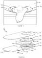
- FIG. 1Bdepicts an elevation view of a pendulous breast interfacing with an embodiment of the system
- FIG. 1Cdepicts a side view of a pendulous breast interfacing with an embodiment of the system, including exposure of a patient's axilla and chest wall through a taut membrane;
- FIG. 2Ais an exploded view of a schematic of an embodiment of the patient interface system
- FIG. 2Bis a top view of a portion of an embodiment of the patient interface system
- FIG. 2Cis a side cross-sectional view of a schematic of an embodiment of the patient interface system
- FIG. 3is a side view of a schematic of the base of an embodiment of the patient interface system
- FIG. 4is a perspective cross-sectional view of a schematic of an embodiment of the patient interface system
- FIGS. 5A and 5Bare a perspective cross-sectional view of a schematic of the support assembly and a cross-sectional view of a schematic of the frame of the support assembly, respectively, of an embodiment of the patient interface system;
- FIG. 5Cis a top view of an embodiment of a portion of the support assembly.
- FIG. 6is a schematic of a pressure sensor array in a variation of the patient interface system.
- an embodiment of a patient interface system 100 for scanning a volume of tissue protruding from a patientincludes: a base 110 including a planar portion 112 on which the patient can lie prone and a frustoconical portion 120 with a sloped inner surface 122 and defining a base aperture 114 configured to receive the volume of tissue; and a support assembly 130 coupled to the base 110 including a frame 140 and membrane 150 disposed within the frame 140 and defining a membrane aperture 152 aligned with the base aperture 114 for receiving the volume of tissue.
- the frame 140 of the support assembly 130is preferably coupled to the frustoconical portion 120 of the base and preferably surrounds the base aperture 114 .
- the membrane 150 of the support assembly 130is preferably disposed within the frame 140 and configured to conform to the body wall of the patient (thereby increasing access to the volume of tissue) and deflect into the sloped inner surface of the base in response to weight of the patient.
- the support assembly 130 and/or membrane 150can be selected from a set of support assemblies and/or membranes that are sized differently (e.g. different sizes of membrane aperture 152 ) to allow optimization for patients of differing builds.
- the system 100can further include a table topper 116 configured to couple to planar portion 112 of the base 100 , and a pressure sensor array 160 distributed proximal to a patient contact surface of the support assembly 130 , wherein the pressure sensor array 160 is configured to generate signals that facilitate patient alignment in response to the weight of the patient.
- the system 100can additionally include a processor 170 configured to generate an analysis based upon signals generated by the pressure sensor array 160 , and a retaining module 180 configured to retain the patient in a desired configuration at the patient interface system 100 .
- the patient interface system 100functions to position a patient and volume of tissue in place for an image scan, in order to ensure proper patient positioning and to facilitate a reduction in the amount of unnecessary scans taken (e.g., due to patient misalignment).
- the patient interface system 100is configured to be placed over an ultrasound imaging tank 102 , which receives the volume of tissue extending through the membrane and base apertures 114 , 152 during an ultrasound tomographic scan, such as for imaging breast tissue or any other suitable volume of tissue that can extend through the table aperture 114 and membrane aperture 152 .
- an ultrasound imaging tank 102which receives the volume of tissue extending through the membrane and base apertures 114 , 152 during an ultrasound tomographic scan, such as for imaging breast tissue or any other suitable volume of tissue that can extend through the table aperture 114 and membrane aperture 152 .
- embodiments of the system 100preferably allow access to a patient's chest wall and axilla, in order to facilitate scanning of a protruding tissue of the patient (e.g., breast tissue 0 .
- the patient interface system 100preferably allows a ring transducer 104 surrounding the extended breast tissue to have more complete access to the tissue up to the chest wall of the patient.
- the ring transducer 104can be a ring transducer 104 as described in U.S. application Ser. No. 13/756,851 entitled “System and Method for Imaging a Volume of Tissue” and filed on 1 Feb. 2013, which is incorporated herein in its entirety by this reference, or any other suitable ring transducer 104 .
- embodiments of the system 100can enable access to and scanning of any other suitable tissue of a patient.
- the patient interface system 100is preferably modular to provide a customizable interface for various patients of differing builds, and comfortable for patients to encourage regular screenings and early cancer detection.
- the patient interface system 100can alternatively be non-modular. Additionally, the patient interface system 100 can be used in conjunction with any suitable imaging modality, or for any suitable purpose involving substantially complete access to volume of tissue (e.g., for scanning using another imaging modality, for biopsy, for surgical procedures, etc.).
- the base 110functions to support the weight of a prone patient, and is preferably configured to provide a surface that spans the entire height and width of the patient, such that the patient's entire body can be supported within the surface of the base. However, the base 110 can alternatively be configured to provide a surface that is shorter that the height of the patient and/or narrower than the width of the patient, such that portions of the patient's body are not supported by the base 110 .
- the base 110preferably includes a planar portion 112 on which the patient can lie prone, and a frustoconical portion 120 with a sloped inner surface 122 configured to provide comfort and allow the volume of tissue to extend into the base aperture 114 .
- the frustoconical portion 120preferably terminates at the base aperture 114 , which provides an opening into the ultrasound imaging tank 102 configured to receive the volume of tissue and facilitate scanning of the volume of tissue.
- the base aperture 114is preferably circular, but in alternative configurations, the base aperture 114 can alternatively be ellipsoidal, oblong, polygonal, or any other suitable shape.
- the frustoconical portion 120 and the base aperture 114are preferably configured to receive and accommodate a single breast of the patient; however, in other variations, the base 110 can be configured to accommodate two breasts and/or multiple protruding tissues (e.g., a face, knees, buttocks, etc.) of the patient, for example, by way of multiple apertures, multiple frustoconical portions, multiple portions displaced from the planar portion 112 of the base, and/or any other suitable element(s) configured to accommodate multiple tissue volumes of the patient.
- tissuee.g., a face, knees, buttocks, etc.
- the base 110can be configured to accommodate a head region of a patient, for instance, with an aperture configured to receive and support a region of a patient's head or face (e.g., a coronal region, a sagittal region, a horizontal region, etc.), as the patient interfaces with the base 110 (e.g., in configuration wherein the patient is lying face down, lying on his/her side, lying face up, and/or in any other configuration).
- a region of a patient's head or facee.g., a coronal region, a sagittal region, a horizontal region, etc.
- planar portion 112 and frustoconical portion 120are preferably separate pieces configured to couple to one another, through complementary nesting (e.g., frustoconical portion 120 seated within a recessed cavity or on a shelf of the planar portion 112 ), interlocking joints, fasteners, by press fit, using adhesives, using magnets, using thermal bonding, or in any suitable manner.
- the planar portion 112 and the frustoconical portion 120can thus be configured to permanently couple to each other, or can be configured to reversibly couple to each other.
- the frustoconical portion 120can be a substitutable portion, such that different frustoconical portions 120 corresponding to different patient morphologies can be provided at the base 110 to enhance patient comfort.
- the frustoconical portion 120can be integrally formed (e.g., physically coextensive, of unitary construction) with one or more parts of the planar portion 112 of the base 100 , for example, by casting.
- the base 110can include any one or more of: a planar surface, a contoured surface (e.g., to a patient's body), frustoconical surface, and any other suitable surface of combination of surfaces to suitably support a particular patient size or shape.
- the base 110is divided along at least one of a long axis 117 and a short axis 118 , such that the planar portion 112 includes two halves, including a head portion 112 a configured to support a superior portion of the patient (e.g., torso, arms, and head) and a foot portion 112 b configured to support an inferior portion of the patient (e.g., legs and feet).
- a head portion 112 aconfigured to support a superior portion of the patient (e.g., torso, arms, and head)
- a foot portion 112 bconfigured to support an inferior portion of the patient (e.g., legs and feet).
- the planar portion 112 of the base 110can alternatively include two unequally sized pieces (e.g., with a relatively longer head portion 112 a or a relatively longer foot portion 112 b ), or fewer or more than two pieces (e.g., pieces that allow customization of the base to support the user's limbs in different configurations, and/or multiple pieces that allow for angular/linear displacement of portions of the base 110 at multiple points along the base).
- the head portion 112 a of the basepreferably includes a region 115 that receives or is coupled to the frustoconical portion 120 and/or the support assembly 130 placed on top of the base 110 .
- the planar portion 112is preferably configured to be oriented in a substantially horizontal configuration, but in alternative variations, any portion of the base 110 can be oriented in and/or adjustable to any suitable relative angle, such as to increase patient comfort or to increase access to areas of the patient that are otherwise difficult to access.
- the base 110 and/or the planar portion 112can be oriented in a substantially vertical configuration (e.g., to form a 75-90° angle in relation to a horizontal plane) for patient comfort (e.g., for patients with back issues).
- the base 110 and/or the planar portion 112can additionally or alternatively be transitioned into a substantially vertical configuration (e.g., to form a 75-90° angle in relation to a horizontal plane) or any other configuration for patient loading, and then transitioned into a desired configuration (e.g., a horizontal configuration) after patient loading, to facilitate imaging in any suitable configuration.
- a substantially vertical configuratione.g., to form a 75-90° angle in relation to a horizontal plane
- a desired configuratione.g., a horizontal configuration
- the relative positions and orientations of multiple portions of the base 110can be adjusted.
- multiple portionscan be coupled to one another in such a manner to allow expansion (e.g., linear expansion) or contraction to accommodate taller or shorter patients.
- multiple portions of the base 110can be slidingly coupled to one another or to a common track (or in any suitable adjustable manner).
- additional separate portions of the base 110can be added or removed from a series of base portions to extend or shorten the length of the base 110 , such as in the manner of a “drop leaf” table.
- each base portion in the series of base portionscan include grooves or other features (e.g., protrusions, recesses) that facilitate alignment, and can additionally or alternatively include couplers (e.g., magnetic couplers, locks, straps, brackets, screws, pins, etc.) that reversibly maintain the position(s) of the base portion(s).
- multiple portionscan be coupled with a hinge or common adjustable framework (or in any suitable adjustable manner) to allow angular adjustment of at least part of the base 110 .
- the adjustable frameworkcan be manually or automatically actuated using an actuator, such as a ratchet mechanism and/or motor (e.g., in response to signals generated by the pressure sensor array 160 described below).
- the head portion 112 a and the foot portion 112 bcan thus be angularly displaced relative to each other about an axis (e.g., the short axis 118 ), in order to tilt the head portion 112 a and/or the foot portion 112 b into inclining and/or declining configurations.
- the base 110preferably includes a lock (e.g., pin, friction lock, or any suitable mechanism) that secures the multiple portions in their relative positions and orientations in a reversible manner.
- a locke.g., pin, friction lock, or any suitable mechanism
- the base 110can additionally or alternatively include multiple sections that can be linearly and/or angularly displaced about any suitable axis at any suitable number of positions along the base 110 .
- the planar portion 112 of the basepreferably includes a rigid material that is compliant with the U.S. Food and Drug Administration (FDA) guidelines; for instance, in a specific example, the planar portion 112 of the base includes Corian® surfaces (e.g., Corian® Whisper surfaces manufactured by DuPontTM) that are compliant with FDA regulation 177.1010.
- the materialis preferably biocompatible, non-porous, and sanitizable.
- the material of the planar portion 112preferably does not interfere with ultrasound signals transmitted and received using a transducer proximal to the base 110 and/or the volume of tissue.
- the material of the base 110can be configured to facilitate reflection of transmitted ultrasound signals in order to enable enhanced analyses of acoustomechanical properties of the volume of tissue, and/or to function as a shield to protect a patient against, for example, harmful types of radiation (e.g., x-ray radiation).
- the planar portion 112 of the basecan additionally or alternatively include any other suitable weight-supportive, biocompatible material.
- the frustoconical portion 120 of the base 110functions to provide a recessed space into which the membrane 150 of the support assembly 130 can deflect, particularly when the membrane 150 of the support assembly 130 supports the body wall of the patient.
- the frustoconical portion 120is preferably configured to extend beyond a plane defined by the planar portion 112 of the base 110 , and can at least partially define the base aperture 114 configured to receive the volume of tissue.
- the frustoconical portion 120is preferably in the approximate shape of a funnel, including a sloped inner surface 122 extending between a narrow end terminating at an opening 123 and a wider end opposed to the narrow end.
- the sloped inner surface 122is preferably linearly sloped from the wider end to the narrower end, and in a specific example defines a slope relative to a horizontal plane of between 20 and 60 degrees.
- the sloped inner surface 122can alternatively include any suitable curvature and/or combination of a curved slope and a linear slope.
- the frustoconical portion 120is preferably oriented such that the narrow end of the frustoconical portion 120 is located below the wider end, in the orientation shown in FIG. 2A .
- the planar portion 112 and the frustoconical portion 120 of the base 110are separate pieces
- the planar portion 112 and the frustoconical portion 120each preferably define respective, aligned base apertures 114 through which the volume of tissue can protrude and be accessible from the underside of the base 110 , in the orientation shown in FIG. 2A .
- alignment of the apertures 114can be facilitated by the frustoconical portion 120 nesting within a complementary region of the planar portion 112 , mechanical alignment keys, visual markings, magnetic elements that facilitate alignment, and/or any suitable features.
- the frustoconical portion 120preferably includes a rigid material that is compliant with the U.S. Food and Drug Administration (FDA) guidelines.
- the frustoconical portion 120includes a polyethylene terephthalate glycol-modified (PETG) surface such as a surface manufactured by Curbell PlasticsTM (e.g., Spectar®/Vivak® surfaces manufactured by Curbell PlasticsTM).
- the frustoconical portion 120 of the base 110can include Corian® surfaces (e.g., Corian® Whisper surfaces manufactured by DuPontTM that are compliant with FDA regulation 177.1010.
- the materialis preferably biocompatible, non-porous, and sanitizable.
- the material of the frustoconical portion 120preferably does not interfere with ultrasound signals transmitted and received using a transducer proximal to the base 110 and/or the volume of tissue.
- the material of the base 110can be configured to facilitate reflection of transmitted ultrasound signals in order to enable enhanced analyses of acoustomechanical properties of the volume of tissue and/or to function as a shield to protect a patient against, for example, harmful types of radiation (e.g., x-ray radiation).
- the frustoconical portion 120 of the base 110can additionally or alternatively include any other suitable weight-supportive, biocompatible material that can be processed to form the frustoconical portion 120 .
- the base 110defines a symmetric obround surface with a long axis 117 and a short axis 118 , wherein the frustoconical portion 120 is biased toward an end of the long axis 117 , in order to accommodate a volume of breast tissue of a prone patient interfacing with the system 100 .
- the frustoconical portion 120is aligned with the long axis 117 , such that the long axis 117 defines an axis of symmetry for the base aperture 114 .
- the base 110is configured to be wider than the width of the patient, such that the patient can shift his/her lateral position relative to the long axis 117 in order to pass each breast through the medially positioned base aperture 114 .
- the base 110is configured to be adjustable at the short axis 118 , such that the short axis 118 defines two halves of the base 110 that can be adjusted and manipulated relative to each other (e.g., as in FIG. 3 ) in order to provide multiple configurations (e.g., tilted configurations, expanded configurations, contracted configurations) that can customize the base 110 to the patient's body and/or provide better access to the volume of tissue.
- the frustoconical portion 120can be unaligned with the long axis 117 (e.g., to target a right or left breast of the patient in a customizable manner), such that the frustoconical portion 120 is biased in one direction along an axis parallel to the short axis 118 (e.g., in order to accommodate one breast or the contralateral breast), and/or the base 100 can be unadjustable at the short axis 118 to provide a fixed configuration of the base 110 .
- the frustoconical portion 120can be adjustable in a direction parallel to the short axis 118 and/or the long axis 118 (e.g., using a sliding track) in order to accommodate a single breast of the patient in one configuration, and a contralateral breast of the patient in another configuration of the frustoconical portion 120 .
- the system 100can additionally include a table topper 116 disposed on the planar portion 112 of the base 110 .
- the table topper 116can be processed to match the footprint of the base 110 , including an aperture to expose the support assembly 130 .
- the aperture of the table toppercan alternatively be configured to hide all or a portion of the support assembly 130 .
- the table topper 116includes a cushion, such a foam pad (e.g., memory foam) or suitable upholstered cushioning, that provides a comfortable surface for the patient to lie down on.
- the table topper 116includes a planar slab of medical foam processed (e.g.
- the table topper 116additionally or alternatively includes a contoured, substantially non-planar surface that can position the patient into a more ergonomic or comfortable body position, and/or can position the patient such that the breast tissue is in better position for scanning.
- the table topper 116can be processed to define recessed and/or protruding regions for any one or more of: the patient's chest, the patient's abdomen, the patient's knees, the patient's feet, and any other suitable body party of the patient.
- the table topper 116can additionally be one of a set of multiple table toppers of various sizes, such that a particular table topper can be substituted in a modular manner into the patient interface system 100 to optimally accommodate patients of various morphologies.
- the table topper 116can include a particulate and/or pliable filling that can be manipulated (e.g., molded) to accommodate different users. As such, the particulate filling can be pushed around or molded, for example, within a casing, in order to mold the table topper 116 to the patient's body.
- the table topper 116preferably includes an external non-porous surface that can easily be disinfected or wiped clean between patients (e.g., vinyl).
- the table topper 116can additionally or alternatively be additionally covered with a protective cover that can be disposed of and replaced by a new cover after a patient interfaces with the patient interface system 100 .
- the table topper 116includes a polyurethane foam encased within a vinyl covering, wherein the polyurethane foam and the vinyl covering are compliant with the U.S. Food and Drug Administration (FDA) guidelines.
- the polyurethane foamis processed to be water repellant, and is biocompatible and sanitizable.
- the material of the table topper 116preferably does not interfere with ultrasound signals transmitted and received using a transducer proximal to the base 110 and/or the volume of tissue.
- the material of the table topper 116can be configured to facilitate reflection of transmitted ultrasound signals in order to enable enhanced analyses of acoustomechanical properties of the volume of tissue, and/or can function as a shield in variations of the system 100 configured to interface with imaging modalities involving, for example, more harmful forms of radiation (e.g., x-ray radiation).
- the table topper 116can additionally or alternatively include any other suitable conforming, biocompatible material that facilitates patient comfort when interfacing with the system 100 .
- the support assembly 130functions to simultaneously facilitate patient comfort and to allow a volume of tissue of the patient to extend through the base aperture 114 into a tank 102 for tissue scanning.
- the support assembly 130includes a frame 140 and a membrane 150 disposed within the frame 140 and configured to conform to the body wall and deflect into the inner surface of the frustoconical portion 120 of the base 110 .
- the support assembly 130is configured to couple to the base 110 such that a membrane aperture 152 of the membrane 150 is aligned with the base aperture 114 , and such that a volume of tissue of the patient can pass through both the membrane aperture 152 and the base aperture 114 .
- the support assembly 130can be one of a set of multiple support assemblies that include membrane apertures of various sizes and/or locations relative to the frame 140 , such that a particular support assembly 130 can be reversibly substituted in a modular manner into the patient interface system 100 to accommodate variations in patient morphology.
- a first support assembly 130can include a larger membrane aperture 152 for scanning a breast of a patient with larger breasts
- a second support assembly 130can include a smaller membrane aperture 152 for scanning a breast of a patient with smaller breasts.
- the support assembly 130can be a non-substitutable element of the system 100 , and can still accommodate variations in patient morphology in any other suitable manner.
- the support assembly 130can include a set of pre-cut inserts (e.g., inserts with different sized apertures, inserts with different material properties, etc.) that can be positioned superior to or inferior to the membrane 150 and aligned relative to the membrane aperture 152 in any suitable manner, in order to accommodate different sized breasts without requiring the tension of the membrane to be adjusted.
- the support assembly 130may not be configured to accommodate variations in patient morphology.
- different support assemblies 130can include different numbers and/or configurations of membrane apertures 152 for accommodating both breasts of a patient and/or other tissues of a patient.
- the patient interface system 100includes a frame 140 and a membrane 150 that is one of a set of multiple membranes, such that a particular membrane 150 can be swapped in a modular manner to couple to the frame 140 .
- a first membrane configured to be retained within the frame 140can include a larger membrane aperture 152 for scanning a breast of a patient with larger breasts
- a second membrane configured to be substituted for the first membranecan include a smaller membrane aperture 152 for scanning a breast of a patient with smaller breasts.
- membranescan include different numbers and/or configurations of membrane apertures 152 for accommodating both breasts of a patient and/or other tissues of a patient.
- the support assemblyincludes a single frame 140 and replaceable membranes 150 that are configured for different applications.
- the patient interface system 100can include any suitable number of frames and/or membranes 150 that can be combined in any suitable manner to optimize position, comfort, and/or scanning access to the tissue for various patients.
- the frame 140 of the support assembly 130functions to provide structural support to the membrane 150 and couples the membrane 150 to the base 110 .
- the frame 140can additionally function to maintain the membrane 150 in tension at a peripheral portion of the membrane 150 , such that the membrane 150 provides a counteracting force in response to the weight of the patient's body.
- the frame 140may not be configured to retain the membrane 150 in tension.
- the frame 140is preferably annular, forms a closed perimeter about the membrane 150 , and can be circular or ellipsoidal; however, the frame 140 can alternatively form an open perimeter about a portion of the membrane 150 and/or define any other suitable shape (e.g., regular polygonal shape, irregular polygonal shape, irregular curvilinear shape).
- the frame 140preferably includes at least a frame base 142 , which functions to provide coupling locations to secure the membrane 150 to the frame 140 in a reversible manner.
- the frame base 142can additionally or alternatively function to provide surfaces that allow coupling of the membrane 150 to the frame 140 in a reversible manner.
- the frame base 142preferably couples to or abuts the frustoconical portion 120 of the base 110 at an inferior surface 147 of the frame base 142 , but can additionally or alternatively couple to the planar portion 112 or other suitable portion of the base 110 . In one example, as shown in FIGS.
- the frame base 142is preferably annular and configured to nestle and be seated within an annular recess 143 formed circumferentially between the frustoconical portion 120 and the planar portion 112 of the base 110 , such that an inferior surface of the frame base 142 abuts the frustoconical portion 120 .
- the frustoconical portion 120is configured to define two perpendicular walls of the annular recess 143
- the planar portion 112is configured to define a third wall of the annular recess 143 , wherein the third wall is substantially opposed to and/or concentric with one of the walls defined by the frustoconical portion 120 .
- the frame base 142can alternatively be configured to be seated within an annular recess defined circumferentially in the frustoconical portion 120 , within an annular recess defined circumferentially in the planar portion 112 of the base 110 , or within a recess defined by the frustoconical portion 120 and/or the planar portion 112 in any other suitable manner.
- the recess and/or corresponding mating portion of the frame base 142can be non-annular, the frame base 142 can be configured to only be partially seated within the recess, and the frame base 112 and the recess can be configured for coupling in any other suitable manner.
- the frame base 142can couple to the base 110 with a snap fit, press fit, friction fit, latches, straps, magnetic elements, and/or in any suitable manner.
- the frame base 142 and/or the base 110can include alignment features to orient the support assembly 130 in a particular matter relative to the base 110 .
- alignment featurescan include, for example, visual markings or physical interference features (e.g., ellipsoidal shape of the frame, mechanical keys, magnetic aligners).
- the frame base 142includes a rigid polymer, such as polyethylene terephtalate glycol-modified (PETG), but can additionally or alternatively include any suitable material.
- PETGpolyethylene terephtalate glycol-modified
- the frame base 142can be injection-molded, but can alternatively be milled, 3D-printed, casted, or manufactured in any suitable manner.
- the membrane 150is preferably coupled in tension across the frame 140 of the support assembly 130 and configured to be positioned over the frustoconical portion 120 of the base 110 when the support assembly 130 is coupled to the base 110 , and preferably defines a membrane aperture 152 that receives the volume of tissue.
- the membrane 150includes a flexible polymer such as urethane and can be coupled to the support assembly 130 using, for example, mechanical fasteners, an adhesive, coupling using magnetic elements, and/or thermal welding.
- the membrane 150can alternatively include any suitable material and be coupled with any suitable fixation method.
- the membrane 150When a patient lies prone on the table surface and the volume of tissue (e.g., a volume of breast tissue) extends through the membrane aperture 152 , the membrane 150 preferably deflects downward into the inner sloped surface 122 of the frustoconical portion 120 of the base 110 and conforms to the body wall around the volume of tissue, due to the weight of the patient on the support assembly 130 .
- the membrane 150is preferably one of a set of membranes with varying dimensions, such as in size, shape (e.g., circular, ellipsoidal, rectangular), number of apertures, and location (e.g., centered or off-centered relative to the frame 140 or relative to the base 110 ) of the membrane aperture 152 .
- the set of membranescan additionally or alternatively vary in any suitable aspect, such as material type or thickness.
- material typecan vary to accommodate patients with skin contact allergies, or can be stronger (e.g., have a higher tensile modulus, have greater fracture resistance) to provide extra patient support without requiring a substantially thicker membrane 150 .
- the support assembly 130can further include a bezel 144 or rim coupled to the frame base 142 (e.g., a superior surface of the frame base 142 ) and circumferentially surrounding the membrane 150 .
- the bezel 144functions to facilitate coupling of the membrane 150 to the frame 140 , such that the membrane 150 can be retained between the frame base 142 and the bezel 144 at a peripheral portion of the membrane 150 .
- the bezel 144is thus preferably a separate piece from the frame base 142 , but can alternatively be integrally formed with the frame base 142 or other component of the support assembly 130 in a manner that allows a portion of the membrane 150 to be seated between the bezel and the frame base 142 or other component of the support assembly 130 .
- the bezel 144 and the frame base 142can be integrally formed along an edge, in a manner that provides a circumferential gap between the bezel 144 and the frame base 142 , wherein the circumferential gap can receive the membrane 150 .
- the bezel 144is preferably proximal to a superior surface 149 of the frame base 142 by a series of rivets or other mechanical fasteners 141 distributed around the border of the support assembly 130 .
- the rivets/mechanical fastenerscan provide a compressive force that retains the membrane 150 between the bezel 144 and the frame base 142 , and/or can pass through openings in the membrane 150 to lock the membrane in place relative to the bezel 144 and the frame base 142 .
- the series of mechanical fasteners 141are preferably arranged uniformly about the border of the support assembly 130 , but can additionally or alternatively include fasteners that are clustered or randomly distributed about the border of the support assembly 130 .
- a series of mechanical fastenerssandwiches the membrane 150 between the bezel 144 and the frame base 142 , thereby securing the membrane 150 to the support assembly 130 .
- the series of mechanical fastenersmay not provide a compressive force, but may instead bias the bezel 144 toward the frame base 142 while coupling a peripheral portion of the membrane 150 between the bezel 144 and the frame base 142 (e.g., a fastener can be configured to pass through an opening in the membrane that is aligned with openings in the bezel 144 and the frame base 142 ).
- the bezel 144can couple to the frame 140 with a snap fit, an adhesive, magnetic couplers, or any suitable fastening mechanism.
- the bezel 144preferably includes the same material as the frame base 142 , but can alternatively include one or more materials that are different from the frame base 142 .
- the support assembly 130can also include a tensioning ring 146 , disposed adjacent to the membrane 150 , at a radially inner side of the bezel 144 for maintaining the tension across the membrane 150 .
- the tensioning ring 146is preferably arranged concentrically with the frame base 142 and/or bezel 144 and underneath the membrane 150 in the orientation shown in FIG. 5B , such that the membrane 150 is stretched in suitable tension to support the patient weight.
- a peripheral portion of the membrane 150is retained between the tensioning ring 146 and the bezel 144 in order to maintain tension across the membrane 150 .
- the amount of membrane tensioncan be fixed and dependent on, for example, the thickness of the tensioning ring 146 , and/or of a spacer 148 configured to displace the tensioning ring 146 from the frame base 142 , wherein an increased height of the spacer 148 /tensioning ring 146 can result in greater tension and a decreased height of the spacer 148 /tensioning ring 146 can result in reduced tension.
- the tensioning ring 148 and/or the spacer 148can be substitutable elements, such that the amount of tension across the membrane can be manipulated by using tensioning rings 146 and/or spacers 148 of different thicknesses.
- the spacer 148is preferably annular and configured to match a footprint of the tensioning ring 146 ; however, the spacer 148 can alternatively be defined by any other suitable geometry and/or footprint.
- the spacer 148can define a non-continuous surface that abuts the tensioning ring 146 at certain locations.
- the amount of membrane tensioncan additionally or alternatively be adjustable, such as to maintain a particular desired amount of tension over repeated stress on the membrane 150 due to repeated uses of the support assembly 130 .
- the thickness or elevation of the tensioning ring 146 and/or of the spacer 148can be adjusted (e.g., using a mechanism to expand the thickness of the tensioning ring 146 and/or the spacer 148 ) to obtain a suitable amount of membrane tension.
- the tensioning ring 146 and/or spacer 148can include the same material as the frame base 142 , but can alternatively include one or more materials that are different from the frame base 142 .
- the support assembly 130can, however, include any other suitable element(s) for maintaining and/or adjusting tension across the membrane 150 .
- the membrane 150can be configured to be retained at one of a set of peripheral regions 157 , as shown in FIG. 5C , wherein each peripheral region of the set of peripheral regions 157 includes an annular band of the membrane 150 .
- retaining a radially inner band of the set of peripheral regionscan contribute to increased tension across the membrane 150
- retaining a radially outer band of the set of peripheral regionscan contribute to decreased tension across the membrane 150 .
- the membrane 150can be retained at a peripheral region between the bezel 144 and the frame base 142 , or in any other suitable manner.
- variations of the support assembly 130can, however, include any suitable combination of the above described variations and examples.
- a variation of the support assembly 130can include a spacer 148 and a membrane 150 with a set of peripheral regions 157 , such that the tension across the membrane 150 can be adjusted using at least one of two features.
- the system 100can entirely omit elements that facilitate tensioning of the membrane 150 .
- a patient's weightcan provide an amount of tension that allows the patient's breast, axilla, and chest wall to protrude through the membrane aperture 152 , in variations of the system 100 for imaging a volume of breast tissue.
- the support assembly 130additionally includes an electrical subsystem coupled to the base 110 and/or support assembly 130 .
- the electrical subsystemcan include a pressure sensor array 160 distributed on a patient contact surface of the support assembly 130 .
- the pressure sensor array 160can be embedded in a sheet coupled to the frame base 142 and/or membrane 150 , such that multiple pressure sensors 162 are distributed around the support assembly 130 and are configured to generate signals in response to the patient's weight and/or in response to a distribution of the patient's weight across the membrane 150 .
- the sheetcan include a flexible polymer such as urethane, preferably similar to the membrane 150 .
- the pressure sensor array 160can be configured relative to the frame base 142 and/or the membrane 150 in any other suitable manner. Furthermore, the pressure sensor array 160 can include any suitable number of pressure sensors in any suitable configuration (e.g., evenly distributed, distributed in a clustered manner, distributed randomly, distributed in a radial configuration, etc.) relative to the base 110 and/or the support assembly 130 .
- the electrical subsystemcan include a conditioning module 164 , which functions to preprocess signals generated by the pressure sensor array 160 prior to transmission to a processor 170 .
- the conditioning module 164preferably comprises signal conditioning elements, including one or more of: an analog-to-digital converter (e.g., to convert analog signals from the pressure sensor array 160 ), an amplifier, and a filter for processing signals prior to transmission.
- the conditioning module 164can include a microprocessor configured to direct signal conditioning functionalities of the conditioning module 138 and a voltage regulator configured to protect elements of the electrical subsystem from overvoltage and/or under-voltage states.
- the pressure sensor array 160can be used to confirm application of approximately uniform pressure at the membrane 150 (e.g., at a peripheral portion of the membrane, across the membrane) from the patient weight.
- the pressure sensor array 160can be used to confirm that the body wall of the patient is seated as evenly on the membrane 150 as possible and the volume of tissue is extended as fully as possible through the membrane aperture 152 , thereby facilitating a complete imaging scan of the volume of tissue.
- the pressure sensor array 160can be calibrated to a certain non-uniform pressure distribution that provides a desired patient configuration relative to the patient interface system 100 , which can be used to maintain any suitable position of the patient to achieve good scanning results.
- the pressure sensor array 160can be used for any suitable purpose, or variations of the system can entirely omit the pressure sensor array 160 .
- the electrical subsystemcan additionally or alternatively include any other suitable electrical components.
- the system 100can include a processor 170 , which functions to receive a set of signals from the pressure sensor array 160 and/or the signal conditioning module 164 , and to generate an analysis of the set of signals in order to guide patient placement at the patient interface system 100 .
- the processor 170can thus comprise a first module 171 configured to receive the set of signals from the pressure sensor array 160 , and a second module 172 configured to generate an analysis from the set of signals.
- the analysiscan confirm a uniform pressure distribution resulting from the patient's weight at the patient interface system 100 .
- the analysiscan confirm a desired non-uniform pressure distribution resulting from the patient's weight at the patient interface system 100 .
- the analysiscan confirm an undesired uniform pressure distribution and/or an undesired non-uniform pressure distribution resulting from the patient's weight at the patient interface system 100 .
- a uniform pressure distribution and/or a non-uniform pressure distribution confirmed by the analysiscan then be used to guide or adjust the patient's configuration (e.g., torso position, body wall position, etc.) in order to facilitate scanning.
- guidancecan be provided, as facilitated by the analysis generated by the processor 170 , using visual and/or audio means for transmitting information.
- the analysiscan be used to generate a rendering at a user interface 185 including a display configured to depict a current position of the patient, and a desired position of the patient that will produce a more desired pressure distribution.
- the analysiscan be used to provide audio or text-based instructions to the patient and/or an operator (e.g., using a visual display, using a speaker), wherein the instructions facilitate adjustment of the patient's configuration relative to the patient interface system 100 .
- the instructionscan provide suggested system 100 configurations including one or more of: tilt angles of the planar portion 112 and/or the frustoconical portion 120 of the base 110 , expanded and/or contracted configurations of the base 110 , appropriate membrane sizes, appropriate membrane aperture sizes, appropriate tensioning ring 146 and/or spacer 148 thicknesses to achieve a desired tension across the membrane 150 , and any other suitable configuration of any element of the system 100 .
- the instructionscan be provided to a controller 178 configured to automatically adjust system element configurations (e.g., tilt angles of the planar portion 112 and/or the frustoconical portion 120 of the base 110 , expanded and/or contracted configurations of the base 110 , appropriate membrane sizes, appropriate membrane aperture sizes, appropriate tensioning ring 146 and/or spacer 148 thicknesses, etc.) using an actuation subsystem 179 configured to manipulate a configuration of at least one element of the system 100 .
- system element configurationse.g., tilt angles of the planar portion 112 and/or the frustoconical portion 120 of the base 110 , expanded and/or contracted configurations of the base 110 , appropriate membrane sizes, appropriate membrane aperture sizes, appropriate tensioning ring 146 and/or spacer 148 thicknesses, etc.
- the system 100can additionally include a retaining module 180 , which functions to retain the patient in a desired configuration once the patient has been properly positioned relative to the patient interface system 100 .
- the retaining module 180can directly retain the patient's torso in a specific configuration, or can additionally or alternatively retain one or more of the patient's limbs/extremities to constrain patient motion.
- the retaining module 180can additionally or alternatively retain the patient's head/neck in a specific configuration to further limit patient movement.
- the retaining module 180can include one or more of: a belt, a strap, a cuff, a band, and any other suitable retaining element.
- the retaining module 180preferably includes adjustable elements (e.g., adjustable straps, elastic bands, etc.) configured to provide an amount of restraint that constricts motion of the patient while still allowing patient comfort.
- the retaining element(s)can be coupled to the base 110 , the support assembly 130 , the table topper 116 , and/or any other suitable portion of the system 100 in a manner that retains a configuration of the patient relative to the system 100 .
- Preferred embodiments of the preferred patient interface system 100include every combination of the base 110 , the support assembly 130 , the processor 170 , the controller 178 , the actuation subsystem 179 , and the restraining module 180 , and their respective components, including the planar portion 112 and the frustoconical portion 120 of the base 110 , the table topper 116 , frame 140 , the membrane 150 , the tensioning ring 146 , the spacer 148 , the pressure sensor array 160 , and the conditioning module 164 of the support assembly 130 .
- the system 100can omit any one or more of the above described elements.
- variations of the system 100can omit the pressure sensor array 160 , and can additionally or alternatively omit the tensioning ring(s) 146 , the spacer(s) 148 , and any other element configured to facilitate tensioning of the membrane 150 .
- the patient interface systempositions the breast of a patient to be scanned for ultrasound tomography.
- This example implementationis for illustrative purposes only, and should not be construed as definitive or limiting in scope of the claimed invention.
- a system operator or othertranslates various measurements of the patient into a selection of a suitable support assembly to be coupled to the base. These measurements can include any one or more of: breast size, patient weight, patient height, torso width, torso length, and any other suitable measurement, and correspond to a support assembly with at least a particular size of membrane aperture, and possibly to a particular set of adjustments to the base.
- the patientlies prone, stomach-side down, on the cushion of the base, and is positioned such that the breast to be scanned extends through the membrane aperture (and the aligned one or more apertures associated with the base) and into an imaging tank filled with water and an ultrasound transducer.
- Data generated from a pressure sensor array embedded in a flexible sheet coupled to the membrane and analyzed by a processorcan be used to confirm proper positioning of the patient, and/or can be used to reposition the patient relative to the patient interface system, in order to improve data quality captured using the ultrasound transducer.
- the processorcan generate a rendering that is displayed at a user interface accessible to at least one of the patient and the system operator, in order to guide positioning and/or repositioning of the patient at the patient interface system.
- the ultrasound transducercan then be activated to scan the breast tissue while the patient interfaces with the patient interface system, and acoustic data from the transducer can be analyzed by the processor and/or any suitable other processor to generate renderings of the breast based on one or more acousto-mechanical parameters including: acoustic reflection, acoustic attenuation, acoustic speed, and combinations thereof.
Landscapes
- Health & Medical Sciences (AREA)
- Life Sciences & Earth Sciences (AREA)
- Medical Informatics (AREA)
- Biophysics (AREA)
- Nuclear Medicine, Radiotherapy & Molecular Imaging (AREA)
- Pathology (AREA)
- Radiology & Medical Imaging (AREA)
- Engineering & Computer Science (AREA)
- Biomedical Technology (AREA)
- Heart & Thoracic Surgery (AREA)
- Physics & Mathematics (AREA)
- Molecular Biology (AREA)
- Surgery (AREA)
- Animal Behavior & Ethology (AREA)
- General Health & Medical Sciences (AREA)
- Public Health (AREA)
- Veterinary Medicine (AREA)
- Apparatus For Radiation Diagnosis (AREA)
- Gynecology & Obstetrics (AREA)
- Ultra Sonic Daignosis Equipment (AREA)
Abstract
Description
Claims (16)
Priority Applications (1)
| Application Number | Priority Date | Filing Date | Title |
|---|---|---|---|
| US16/155,276US11064974B2 (en) | 2013-03-13 | 2018-10-09 | Patient interface system |
Applications Claiming Priority (3)
| Application Number | Priority Date | Filing Date | Title |
|---|---|---|---|
| US201361778985P | 2013-03-13 | 2013-03-13 | |
| US14/208,181US10123770B2 (en) | 2013-03-13 | 2014-03-13 | Patient support system |
| US16/155,276US11064974B2 (en) | 2013-03-13 | 2018-10-09 | Patient interface system |
Related Parent Applications (1)
| Application Number | Title | Priority Date | Filing Date |
|---|---|---|---|
| US14/208,181ContinuationUS10123770B2 (en) | 2013-03-13 | 2014-03-13 | Patient support system |
Publications (2)
| Publication Number | Publication Date |
|---|---|
| US20190038255A1 US20190038255A1 (en) | 2019-02-07 |
| US11064974B2true US11064974B2 (en) | 2021-07-20 |
Family
ID=51530476
Family Applications (2)
| Application Number | Title | Priority Date | Filing Date |
|---|---|---|---|
| US14/208,181Active2034-05-21US10123770B2 (en) | 2013-03-13 | 2014-03-13 | Patient support system |
| US16/155,276Active2035-07-11US11064974B2 (en) | 2013-03-13 | 2018-10-09 | Patient interface system |
Family Applications Before (1)
| Application Number | Title | Priority Date | Filing Date |
|---|---|---|---|
| US14/208,181Active2034-05-21US10123770B2 (en) | 2013-03-13 | 2014-03-13 | Patient support system |
Country Status (1)
| Country | Link |
|---|---|
| US (2) | US10123770B2 (en) |
Cited By (1)
| Publication number | Priority date | Publication date | Assignee | Title |
|---|---|---|---|---|
| US11877892B2 (en) | 2020-05-08 | 2024-01-23 | Karlsruher Institut für Technologie | Device and method for 3D ultrasound-based reflection and transmission tomography of a body |
Families Citing this family (14)
| Publication number | Priority date | Publication date | Assignee | Title |
|---|---|---|---|---|
| US10123770B2 (en) | 2013-03-13 | 2018-11-13 | Delphinus Medical Technologies, Inc. | Patient support system |
| WO2015138317A1 (en) | 2014-03-10 | 2015-09-17 | Stryker Corporation | Limb positioning system |
| US10143443B2 (en) | 2014-05-05 | 2018-12-04 | Delphinus Medical Technologies, Inc. | Method for representing tissue stiffness |
| US10076304B2 (en) | 2014-07-28 | 2018-09-18 | Delphinus Medical Technologies, Inc. | System for providing scanning medium |
| US10743837B2 (en) | 2014-08-04 | 2020-08-18 | Delphinus Medical Technologies, Inc. | Ultrasound waveform tomography method and system |
| US9951904B2 (en) | 2015-03-24 | 2018-04-24 | Stryker Corporation | Rotatable seat clamps for rail clamp |
| EP3413802B1 (en)* | 2016-02-09 | 2024-07-10 | Delphinus Medical Technologies, Inc. | System for shaping and positioning a tissue body |
| US10368831B2 (en) | 2016-12-02 | 2019-08-06 | Delphinus Medical Technologies, Inc. | Waveform enhanced reflection and margin boundary characterization for ultrasound tomography |
| US11298105B2 (en) | 2017-09-07 | 2022-04-12 | Delphinus Medical Technologies, Inc. | System having anchored interface for shaping and positioning a tissue body |
| EP3784139A4 (en) | 2018-04-27 | 2021-12-29 | Delphinus Medical Technologies, Inc. | System and method for feature extraction and classification on ultrasound tomography images |
| WO2019226873A2 (en)* | 2018-05-25 | 2019-11-28 | Hologic, Inc. | Membrane-based breast compression systems |
| CN110338845A (en)* | 2019-07-03 | 2019-10-18 | 华中科技大学鄂州工业技术研究院 | Ergonomic mattress in breast ultrasound tomography system |
| CN116457746A (en) | 2020-09-18 | 2023-07-18 | 戴尔菲纳斯医疗科技公司 | System and method for image manipulation of a digital stack of tissue images |
| JP7551429B2 (en)* | 2020-09-29 | 2024-09-17 | キヤノン株式会社 | Image forming device |
Citations (231)
| Publication number | Priority date | Publication date | Assignee | Title |
|---|---|---|---|---|
| US3154067A (en) | 1961-10-11 | 1964-10-27 | Robert L Gannon | Body function sensor |
| US3771355A (en) | 1971-09-30 | 1973-11-13 | T Sachs | Ultrasonic inspection and diagnosis system |
| US3881466A (en) | 1973-08-20 | 1975-05-06 | Advanced Diagnostic Res | Ultrasonic cross-sectional imaging system |
| US3886489A (en) | 1974-02-25 | 1975-05-27 | Westinghouse Electric Corp | Ultrasonic image converter and system |
| US3925610A (en) | 1974-08-12 | 1975-12-09 | Bell Telephone Labor Inc | Graphic communications tablet |
| US4015836A (en) | 1975-07-31 | 1977-04-05 | General Electric Company | Mammography table |
| US4028934A (en) | 1975-11-04 | 1977-06-14 | Yeda Research & Development Co. Ltd. | Ultrasonic stereoscopic imaging device |
| US4059010A (en) | 1973-10-01 | 1977-11-22 | Sachs Thomas D | Ultrasonic inspection and diagnosis system |
| US4075883A (en) | 1976-08-20 | 1978-02-28 | General Electric Company | Ultrasonic fan beam scanner for computerized time-of-flight tomography |
| US4105018A (en) | 1976-02-02 | 1978-08-08 | University Of Utah | Acoustic examination, material characterization and imaging of the internal structure of a body by measurement of the time-of-flight of acoustic energy therethrough |
| US4144877A (en) | 1976-08-12 | 1979-03-20 | Yeda Research And Development Co. Ltd. | Instrument for viscoelastic measurement |
| GB2040642A (en) | 1979-01-30 | 1980-08-28 | Standard Telephones Cables Ltd | Transducer |
| US4222274A (en) | 1978-09-15 | 1980-09-16 | Johnson Steven A | Ultrasound imaging apparatus and method |
| US4250894A (en) | 1978-11-14 | 1981-02-17 | Yeda Research & Development Co., Ltd. | Instrument for viscoelastic measurement |
| US4317369A (en) | 1978-09-15 | 1982-03-02 | University Of Utah | Ultrasound imaging apparatus and method |
| US4328707A (en) | 1978-06-20 | 1982-05-11 | Agence Nationale De Valorisation De La Recherche | Ultrasonic image reconstruction methods and apparatus |
| US4363326A (en) | 1980-12-22 | 1982-12-14 | Advanced Diagnostic Research Corporation | Ultrasonic apparatus for needle insertion |
| US4412288A (en) | 1980-04-01 | 1983-10-25 | Michael Herman | Experiment-machine |
| EP0097917A1 (en) | 1982-06-30 | 1984-01-11 | Siemens Aktiengesellschaft | Ultrasonic tomography apparatus |
| US4431008A (en) | 1982-06-24 | 1984-02-14 | Wanner James F | Ultrasonic measurement system using a perturbing field, multiple sense beams and receivers |
| US4433690A (en) | 1981-07-20 | 1984-02-28 | Siemens Ag | Compact ultrasound apparatus for medical examination |
| US4481948A (en) | 1980-12-29 | 1984-11-13 | Sole Gary M | Medical instrument, and methods of constructing and utilizing same |
| US4509368A (en) | 1981-06-22 | 1985-04-09 | The Commonwealth Of Australia | Ultrasound tomography |
| US4515165A (en) | 1980-02-04 | 1985-05-07 | Energy Conversion Devices, Inc. | Apparatus and method for detecting tumors |
| US4541436A (en) | 1982-08-19 | 1985-09-17 | Siemens Aktiengesellschaft | Ultrasonic tomography device |
| US4542744A (en) | 1983-03-23 | 1985-09-24 | North American Philips Corporation | Method and apparatus for remote tissue identification by statistical modeling and hypothesis testing of echo ultrasound signals |
| US4562540A (en) | 1982-11-12 | 1985-12-31 | Schlumberger Technology Corporation | Diffraction tomography system and methods |
| US4564019A (en) | 1982-04-07 | 1986-01-14 | Fujitsu Limited | Method for measuring characteristics of living tissues by ultrasonic waves |
| US4606342A (en) | 1985-02-15 | 1986-08-19 | National Patent Development Corporation | Cautery device having a variable temperature cautery tip |
| US4646756A (en) | 1982-10-26 | 1987-03-03 | The University Of Aberdeen | Ultra sound hyperthermia device |
| US4662222A (en) | 1984-12-21 | 1987-05-05 | Johnson Steven A | Apparatus and method for acoustic imaging using inverse scattering techniques |
| US4671256A (en) | 1984-05-25 | 1987-06-09 | Lemelson Jerome H | Medical scanning, monitoring and treatment system and method |
| US4722056A (en) | 1986-02-18 | 1988-01-26 | Trustees Of Dartmouth College | Reference display systems for superimposing a tomagraphic image onto the focal plane of an operating microscope |
| US4733562A (en) | 1985-07-15 | 1988-03-29 | Siemens Aktiengesellschaft | Method and apparatus for ultrasonic scanning of an object |
| EP0284055A2 (en) | 1987-03-26 | 1988-09-28 | Washington Research Foundation | Endoscopically deliverable ultrasound imaging system |
| EP0317049A2 (en) | 1987-11-13 | 1989-05-24 | Advanced Diagnostic Medical Systems, Inc. | Ultrasonic probe |
| EP0320444A1 (en) | 1987-11-25 | 1989-06-14 | Laboratory Equipment, Corp. | Portable ultrasonic probe |
| US4855911A (en) | 1987-11-16 | 1989-08-08 | Massachusetts Institute Of Technology | Ultrasonic tissue characterization |
| US4858124A (en) | 1984-08-15 | 1989-08-15 | Riverside Research Institute | Method for enhancement of ultrasonic image data |
| EP0351610A2 (en) | 1988-07-01 | 1990-01-24 | Hitachi, Ltd. | Ultrasonic apparatus for therapeutical use |
| US4932414A (en) | 1987-11-02 | 1990-06-12 | Cornell Research Foundation, Inc. | System of therapeutic ultrasound and real-time ultrasonic scanning |
| US4941474A (en) | 1988-07-01 | 1990-07-17 | Massachusetts Institute Of Technology | Multivariable analysis of bone condition |
| US5003979A (en) | 1989-02-21 | 1991-04-02 | University Of Virginia | System and method for the noninvasive identification and display of breast lesions and the like |
| US5025792A (en) | 1985-09-26 | 1991-06-25 | The Hon Group | Continuous cutaneous blood pressure measuring apparatus and method |
| US5029476A (en) | 1989-09-07 | 1991-07-09 | Westinghouse Electric Corp. | Ultrasonic system for determining the profile of solid bodies |
| US5095909A (en) | 1988-05-26 | 1992-03-17 | Fujitsu Limited | Ultrasound diagnostic equipment |
| US5103129A (en) | 1990-07-26 | 1992-04-07 | Acoustic Imaging Technologies Corporation | Fixed origin biplane ultrasonic transducer |
| US5143069A (en) | 1989-04-24 | 1992-09-01 | Orthosonics, Inc. | Diagnostic method of monitoring skeletal defect by in vivo acoustic measurement of mechanical strength using correlation and spectral analysis |
| US5158536A (en) | 1989-08-28 | 1992-10-27 | Biopulmonics, Inc. | Lung cancer hyperthermia via ultrasound and/or convection with perfiuorochemical liquids |
| US5178147A (en) | 1989-11-17 | 1993-01-12 | Board Of Regents, The University Of Texas System | Method and apparatus for elastographic measurement and imaging |
| US5179455A (en) | 1991-11-22 | 1993-01-12 | Advanced Imaging Systems | Ultrasonic holographic imaging apparatus having an improved optical reconstruction system |
| US5212571A (en) | 1991-11-22 | 1993-05-18 | Advanced Imaging Systems | Ultrasonic holographic imaging apparatus having zoom feature |
| US5255683A (en) | 1991-12-30 | 1993-10-26 | Sound Science Limited Partnership | Methods of and systems for examining tissue perfusion using ultrasonic contrast agents |
| US5260871A (en) | 1991-07-31 | 1993-11-09 | Mayo Foundation For Medical Education And Research | Method and apparatus for diagnosis of breast tumors |
| US5267566A (en) | 1991-03-07 | 1993-12-07 | Maged Choucair | Apparatus and method for blood pressure monitoring |
| US5268876A (en) | 1991-06-25 | 1993-12-07 | The Board Of Trustees Of The Leland Stanford Junior University | Method of estimating near field aberrating delays |
| US5269309A (en) | 1991-12-11 | 1993-12-14 | Fort J Robert | Synthetic aperture ultrasound imaging system |
| US5280788A (en) | 1991-02-26 | 1994-01-25 | Massachusetts Institute Of Technology | Devices and methods for optical diagnosis of tissue |
| US5289520A (en) | 1991-11-27 | 1994-02-22 | Lorad Corporation | Stereotactic mammography imaging system with prone position examination table and CCD camera |
| US5296910A (en) | 1992-10-05 | 1994-03-22 | University Of Akransas | Method and apparatus for particle analysis |
| US5297553A (en) | 1992-09-23 | 1994-03-29 | Acuson Corporation | Ultrasound transducer with improved rigid backing |
| US5304173A (en) | 1985-03-22 | 1994-04-19 | Massachusetts Institute Of Technology | Spectral diagonostic and treatment system |
| US5305752A (en) | 1991-05-31 | 1994-04-26 | Thermotrex Corporation | Acoustic imaging device |
| US5318028A (en) | 1993-06-07 | 1994-06-07 | Westinghouse Electric Corporation | High resolution ultrasound mammography system and boundary array scanner therefor |
| US5329817A (en) | 1991-11-22 | 1994-07-19 | Advanced Imaging Systems | Ultrasonic holography imaging method and apparatus |
| EP0609922A2 (en) | 1993-01-11 | 1994-08-10 | Koninklijke Philips Electronics N.V. | Computer detection of microcalcifications in mammograms |
| US5339282A (en) | 1992-10-02 | 1994-08-16 | University Of Utah Research Foundation | Resolution enhancement for ultrasonic reflection mode imaging |
| EP0614651A1 (en) | 1993-03-10 | 1994-09-14 | Kabushiki Kaisha Toshiba | Ultrasonic wave medical treatment apparatus suitable for use under guidance of magnetic resonance imaging |
| US5349954A (en) | 1993-07-23 | 1994-09-27 | General Electric Company | Tumor tissue characterization apparatus and method |
| US5372138A (en) | 1988-03-21 | 1994-12-13 | Boston Scientific Corporation | Acousting imaging catheters and the like |
| US5394875A (en) | 1993-10-21 | 1995-03-07 | Lewis; Judith T. | Automatic ultrasonic localization of targets implanted in a portion of the anatomy |
| US5398691A (en) | 1993-09-03 | 1995-03-21 | University Of Washington | Method and apparatus for three-dimensional translumenal ultrasonic imaging |
| US5413108A (en) | 1993-04-21 | 1995-05-09 | The Research Foundation Of City College Of New York | Method and apparatus for mapping a tissue sample for and distinguishing different regions thereof based on luminescence measurements of cancer-indicative native fluorophor |
| US5415164A (en) | 1991-11-04 | 1995-05-16 | Biofield Corp. | Apparatus and method for screening and diagnosing trauma or disease in body tissues |
| EP0661029A1 (en) | 1993-12-28 | 1995-07-05 | Kabushiki Kaisha Toshiba | Method and apparatus for ultrasonic medical treatment with optimum ultrasonic irradiation control |
| US5433202A (en) | 1993-06-07 | 1995-07-18 | Westinghouse Electric Corporation | High resolution and high contrast ultrasound mammography system with heart monitor and boundary array scanner providing electronic scanning |
| US5463548A (en) | 1990-08-28 | 1995-10-31 | Arch Development Corporation | Method and system for differential diagnosis based on clinical and radiological information using artificial neural networks |
| US5474072A (en) | 1993-10-29 | 1995-12-12 | Neovision Corporation | Methods and apparatus for performing sonomammography |
| US5485839A (en) | 1992-02-28 | 1996-01-23 | Kabushiki Kaisha Toshiba | Method and apparatus for ultrasonic wave medical treatment using computed tomography |
| US5487387A (en) | 1994-06-03 | 1996-01-30 | Duke University | Method and apparatus for distinguishing between solid masses and fluid-filled cysts |
| US5492126A (en) | 1994-05-02 | 1996-02-20 | Focal Surgery | Probe for medical imaging and therapy using ultrasound |
| US5501655A (en) | 1992-03-31 | 1996-03-26 | Massachusetts Institute Of Technology | Apparatus and method for acoustic heat generation and hyperthermia |
| AU3443295A (en) | 1994-10-21 | 1996-05-02 | Advanced Diagnostic Development Pty Ltd | Collimator arrangements |
| US5513639A (en) | 1994-04-12 | 1996-05-07 | Fujitsu Limited | Balloon type ultrasonic diagnostic probe |
| US5546945A (en) | 1994-09-14 | 1996-08-20 | Siemens Aktiengesellschaft | Method and apparatus for displaying acoustic signal transit times |
| US5548658A (en) | 1994-06-06 | 1996-08-20 | Knowles Electronics, Inc. | Acoustic Transducer |
| US5553618A (en) | 1993-03-12 | 1996-09-10 | Kabushiki Kaisha Toshiba | Method and apparatus for ultrasound medical treatment |
| US5558092A (en) | 1995-06-06 | 1996-09-24 | Imarx Pharmaceutical Corp. | Methods and apparatus for performing diagnostic and therapeutic ultrasound simultaneously |
| US5573497A (en) | 1994-11-30 | 1996-11-12 | Technomed Medical Systems And Institut National | High-intensity ultrasound therapy method and apparatus with controlled cavitation effect and reduced side lobes |
| US5582173A (en) | 1995-09-18 | 1996-12-10 | Siemens Medical Systems, Inc. | System and method for 3-D medical imaging using 2-D scan data |
| US5588032A (en) | 1992-10-14 | 1996-12-24 | Johnson; Steven A. | Apparatus and method for imaging with wavefields using inverse scattering techniques |
| US5588430A (en) | 1995-02-14 | 1996-12-31 | University Of Florida Research Foundation, Inc. | Repeat fixation for frameless stereotactic procedure |
| US5590657A (en) | 1995-11-06 | 1997-01-07 | The Regents Of The University Of Michigan | Phased array ultrasound system and method for cardiac ablation |
| US5596992A (en) | 1993-06-30 | 1997-01-28 | Sandia Corporation | Multivariate classification of infrared spectra of cell and tissue samples |
| US5606971A (en) | 1995-11-13 | 1997-03-04 | Artann Corporation, A Nj Corp. | Method and device for shear wave elasticity imaging |
| US5620479A (en) | 1992-11-13 | 1997-04-15 | The Regents Of The University Of California | Method and apparatus for thermal therapy of tumors |
| EP0774276A2 (en) | 1995-11-15 | 1997-05-21 | Schneider (Usa) Inc. | Apparatus and method for transurethral focussed ultrasound therapy |
| US5640956A (en) | 1995-06-07 | 1997-06-24 | Neovision Corporation | Methods and apparatus for correlating ultrasonic image data and radiographic image data |
| US5660185A (en) | 1995-04-13 | 1997-08-26 | Neovision Corporation | Image-guided biopsy apparatus with enhanced imaging and methods |
| US5664573A (en) | 1993-10-29 | 1997-09-09 | Neovision Corporation | Method and apparatus for performing sonomammography and enhanced X-ray imaging |
| US5673698A (en) | 1994-04-21 | 1997-10-07 | Hitachi Medical Corporation | Multichannel ultrasonic diagnosis apparatus |
| US5678565A (en) | 1992-12-21 | 1997-10-21 | Artann Corporation | Ultrasonic elasticity imaging method and device |
| US5749364A (en) | 1996-06-21 | 1998-05-12 | Acuson Corporation | Method and apparatus for mapping pressure and tissue properties |
| US5759162A (en) | 1992-03-10 | 1998-06-02 | Siemens Aktiengesellschaft | Method and apparatus for ultrasound tissue therapy |
| US5762066A (en) | 1992-02-21 | 1998-06-09 | Ths International, Inc. | Multifaceted ultrasound transducer probe system and methods for its use |
| US5766129A (en) | 1996-06-13 | 1998-06-16 | Aloka Co., Ltd. | Ultrasound diagnostic apparatus and method of forming an ultrasound image by the apparatus |
| US5787049A (en) | 1995-11-07 | 1998-07-28 | Bates; Kenneth N. | Acoustic wave imaging apparatus and method |
| US5785663A (en) | 1992-12-21 | 1998-07-28 | Artann Corporation | Method and device for mechanical imaging of prostate |
| US5797849A (en) | 1995-03-28 | 1998-08-25 | Sonometrics Corporation | Method for carrying out a medical procedure using a three-dimensional tracking and imaging system |
| US5800350A (en) | 1993-11-01 | 1998-09-01 | Polartechnics, Limited | Apparatus for tissue type recognition |
| US5810731A (en) | 1995-11-13 | 1998-09-22 | Artann Laboratories | Method and apparatus for elasticity imaging using remotely induced shear wave |
| US5817025A (en) | 1996-09-30 | 1998-10-06 | Alekseev; Sergei Grigorevich | Method for diagnosing malignancy diseases |
| US5830133A (en) | 1989-09-18 | 1998-11-03 | Minnesota Mining And Manufacturing Company | Characterizing biological matter in a dynamic condition using near infrared spectroscopy |
| US5833634A (en) | 1995-11-09 | 1998-11-10 | Uromed Corporation | Tissue examination |
| US5833627A (en) | 1995-04-13 | 1998-11-10 | United States Surgical Corporation | Image-guided biopsy apparatus and methods of use |
| US5833614A (en) | 1997-07-15 | 1998-11-10 | Acuson Corporation | Ultrasonic imaging method and apparatus for generating pulse width modulated waveforms with reduced harmonic response |
| US5833633A (en) | 1992-12-21 | 1998-11-10 | Artann Laboratories | Device for breast haptic examination |
| US5836882A (en) | 1997-03-17 | 1998-11-17 | Frazin; Leon J. | Method and apparatus of localizing an insertion end of a probe within a biotic structure |
| US5836894A (en) | 1992-12-21 | 1998-11-17 | Artann Laboratories | Apparatus for measuring mechanical parameters of the prostate and for imaging the prostate using such parameters |
| US5846202A (en) | 1996-07-30 | 1998-12-08 | Acuson Corporation | Ultrasound method and system for imaging |
| US5851182A (en) | 1996-09-11 | 1998-12-22 | Sahadevan; Velayudhan | Megavoltage radiation therapy machine combined to diagnostic imaging devices for cost efficient conventional and 3D conformal radiation therapy with on-line Isodose port and diagnostic radiology |
| US5855554A (en) | 1997-03-17 | 1999-01-05 | General Electric Company | Image guided breast lesion localization device |
| US5865167A (en) | 1991-12-17 | 1999-02-02 | Dynamics Imaging, Inc. | Method of living system organism diagnostics and apparatus for its realization |
| US5865743A (en) | 1994-02-23 | 1999-02-02 | Dynamics Imaging, Inc. | Method of living organism multimodal functional mapping |
| US5891619A (en) | 1997-01-14 | 1999-04-06 | Inphocyte, Inc. | System and method for mapping the distribution of normal and abnormal cells in sections of tissue |
| US5945674A (en) | 1997-07-30 | 1999-08-31 | Vysis, Inc. | Method of identifying cellular types in a biological sample supported on an absorptive substrate by infrared spectroscopy |
| WO1999047046A1 (en) | 1998-03-20 | 1999-09-23 | Barbara Ann Karmanos Cancer Institute | Multidimensional detection and characterization of pathologic tissues |
| US6002958A (en) | 1992-12-24 | 1999-12-14 | Dynamics Imaging, Inc. | Method and apparatus for diagnostics of internal organs |
| US6005916A (en) | 1992-10-14 | 1999-12-21 | Techniscan, Inc. | Apparatus and method for imaging with wavefields using inverse scattering techniques |
| US6014473A (en) | 1996-02-29 | 2000-01-11 | Acuson Corporation | Multiple ultrasound image registration system, method and transducer |
| US6023632A (en) | 1997-07-16 | 2000-02-08 | Wilk; Peter J. | Ultrasonic medical system and associated method |
| US6050943A (en) | 1997-10-14 | 2000-04-18 | Guided Therapy Systems, Inc. | Imaging, therapy, and temperature monitoring ultrasonic system |
| US6056690A (en) | 1996-12-27 | 2000-05-02 | Roberts; Linda M. | Method of diagnosing breast cancer |
| US6078677A (en) | 1996-12-23 | 2000-06-20 | Microtronic Nederlands B.V. | Electroacoustic transducer with improved diaphragm attachment |
| US6083166A (en) | 1997-12-02 | 2000-07-04 | Situs Corporation | Method and apparatus for determining a measure of tissue manipulation |
| US6102857A (en) | 1996-10-04 | 2000-08-15 | Optosonics, Inc. | Photoacoustic breast scanner |
| US6109270A (en) | 1997-02-04 | 2000-08-29 | The United States Of America As Represented By The Administrator Of The National Aeronautics And Space Administration | Multimodality instrument for tissue characterization |
| US6117080A (en) | 1997-06-04 | 2000-09-12 | Atl Ultrasound | Ultrasonic imaging apparatus and method for breast cancer diagnosis with the use of volume rendering |
| US6135960A (en) | 1998-08-31 | 2000-10-24 | Holmberg; Linda Jean | High-resolution, three-dimensional whole body ultrasound imaging system |
| US6146897A (en) | 1995-11-13 | 2000-11-14 | Bio-Rad Laboratories | Method for the detection of cellular abnormalities using Fourier transform infrared spectroscopy |
| US6149441A (en) | 1998-11-06 | 2000-11-21 | Technology For Connecticut, Inc. | Computer-based educational system |
| US6165734A (en) | 1995-12-12 | 2000-12-26 | Applied Spectral Imaging Ltd. | In-situ method of analyzing cells |
| US6190334B1 (en) | 1999-05-24 | 2001-02-20 | Rbp, Inc. | Method and apparatus for the imaging of tissue |
| US6235038B1 (en) | 1999-10-28 | 2001-05-22 | Medtronic Surgical Navigation Technologies | System for translation of electromagnetic and optical localization systems |
| US6242472B1 (en) | 1989-08-28 | 2001-06-05 | Alliance Pharmaceutical Corp. | Methods for the pulmonary delivery of biological agents |
| US6245017B1 (en) | 1998-10-30 | 2001-06-12 | Kabushiki Kaisha Toshiba | 3D ultrasonic diagnostic apparatus |
| US6256090B1 (en) | 1997-07-31 | 2001-07-03 | University Of Maryland | Method and apparatus for determining the shape of a flexible body |
| US6289235B1 (en) | 1998-03-05 | 2001-09-11 | Wake Forest University | Method and system for creating three-dimensional images using tomosynthetic computed tomography |
| US6296489B1 (en) | 1999-06-23 | 2001-10-02 | Heuristix | System for sound file recording, analysis, and archiving via the internet for language training and other applications |
| US20010029334A1 (en) | 1999-12-28 | 2001-10-11 | Rainer Graumann | Method and system for visualizing an object |
| US20010037075A1 (en) | 2000-03-15 | 2001-11-01 | The Regents Of The University Of California | Method and apparatus for dynamic focusing of ultrasound energy |
| US6317617B1 (en) | 1997-07-25 | 2001-11-13 | Arch Development Corporation | Method, computer program product, and system for the automated analysis of lesions in magnetic resonance, mammogram and ultrasound images |
| US20010051774A1 (en) | 2000-02-28 | 2001-12-13 | Peter Littrup | Multidimensional bioelectrical tissue analyzer |
| US6351660B1 (en) | 2000-04-18 | 2002-02-26 | Litton Systems, Inc. | Enhanced visualization of in-vivo breast biopsy location for medical documentation |
| US6368275B1 (en) | 1999-10-07 | 2002-04-09 | Acuson Corporation | Method and apparatus for diagnostic medical information gathering, hyperthermia treatment, or directed gene therapy |
| WO2002028350A2 (en) | 2000-10-06 | 2002-04-11 | Advanced Medical Applications, Inc. | Nozzle for ultrasound and wound treatment |
| WO2002030288A1 (en) | 2000-10-11 | 2002-04-18 | Forschungszentrum Karlsruhe Gmbh | Ultrasonic tomograph |
| US6385474B1 (en) | 1999-03-19 | 2002-05-07 | Barbara Ann Karmanos Cancer Institute | Method and apparatus for high-resolution detection and characterization of medical pathologies |
| US6413219B1 (en) | 1999-03-31 | 2002-07-02 | General Electric Company | Three-dimensional ultrasound data display using multiple cut planes |
| US20020099290A1 (en) | 2000-12-01 | 2002-07-25 | The Regents Of The University Of California. | System and method for ultrasonic tomography |
| US6425869B1 (en) | 2000-07-18 | 2002-07-30 | Koninklijke Philips Electronics, N.V. | Wideband phased-array transducer for uniform harmonic imaging, contrast agent detection, and destruction |
| US6428477B1 (en) | 2000-03-10 | 2002-08-06 | Koninklijke Philips Electronics, N.V. | Delivery of theraputic ultrasound by two dimensional ultrasound array |
| US20020120196A1 (en) | 2000-12-28 | 2002-08-29 | Dubberstein David T. | Refraction delay error correction using agile beamformer |
| US6450960B1 (en) | 2000-08-29 | 2002-09-17 | Barbara Ann Karmanos Cancer Institute | Real-time three-dimensional acoustoelectronic imaging and characterization of objects |
| US6451013B1 (en) | 2000-01-19 | 2002-09-17 | Medtronic Xomed, Inc. | Methods of tonsil reduction using high intensity focused ultrasound to form an ablated tissue area containing a plurality of lesions |
| US6478739B1 (en) | 2001-05-11 | 2002-11-12 | The Procter & Gamble Company | Ultrasonic breast examination system |
| US6511427B1 (en) | 2000-03-10 | 2003-01-28 | Acuson Corporation | System and method for assessing body-tissue properties using a medical ultrasound transducer probe with a body-tissue parameter measurement mechanism |
| US6527759B1 (en) | 1995-03-05 | 2003-03-04 | Ekos Corporation | Ultrasound assembly for use with light activated drugs |
| US6559178B1 (en) | 2002-01-29 | 2003-05-06 | Mark Zamoyski | Compositions and methods for apoptotic chemosurgery |
| US6574499B1 (en) | 1998-11-25 | 2003-06-03 | Xdata Corporation | Mammography method and apparatus |
| US6587540B1 (en) | 1992-10-14 | 2003-07-01 | Techniscan, Inc. | Apparatus and method for imaging objects with wavefields |
| US20030138053A1 (en) | 2001-11-15 | 2003-07-24 | The Regents Of The University Of California | Time reversal communication system |
| US6612988B2 (en) | 2000-08-29 | 2003-09-02 | Brigham And Women's Hospital, Inc. | Ultrasound therapy |
| US6645202B1 (en) | 1996-10-22 | 2003-11-11 | Epicor Medical, Inc. | Apparatus and method for ablating tissue |
| US20040030227A1 (en) | 2002-05-16 | 2004-02-12 | Barbara Ann Karmanos Cancer Institute | Method and apparatus for combined diagnostic and therapeutic ultrasound system incorporating noninvasive thermometry, ablation control and automation |
| US20040059265A1 (en) | 2002-09-12 | 2004-03-25 | The Regents Of The University Of California | Dynamic acoustic focusing utilizing time reversal |
| US6716412B2 (en) | 1997-09-15 | 2004-04-06 | Imarx Therapeutics, Inc. | Methods of ultrasound treatment using gas or gaseous precursor-filled compositions |
| US20040081273A1 (en) | 1999-11-18 | 2004-04-29 | Ruola Ning | Apparatus and method for cone beam volume computed tomography breast imaging |
| US20040122325A1 (en) | 2002-12-18 | 2004-06-24 | Barbara Ann Karmanos Cancer Institute | Diagnostic analysis of ultrasound data |
| WO2004061743A2 (en) | 2002-12-18 | 2004-07-22 | Ge Medical Systems Global Technology Company, Llc | Integrated medical knowledge base interface system and method |
| US20040152986A1 (en) | 2003-01-23 | 2004-08-05 | Fidel Howard F. | Ultrasonic imaging device, system and method of use |
| US6776760B2 (en) | 2002-03-06 | 2004-08-17 | Alfred E. Mann Institute For Biomedical Engineering At The University Of Southern California | Multi-mode processing for ultrasonic imaging |
| US20040167396A1 (en) | 2003-02-25 | 2004-08-26 | The Regents Of The University Of California | Quantitative full aperture tomography imaging system and method |
| US6785570B2 (en) | 2000-12-22 | 2004-08-31 | Md Medical Diagnostics Inc. | System and method for analysis of a tissue |
| US20040181154A1 (en) | 2003-03-13 | 2004-09-16 | Roy Peterson | Ultrasonic diagnostic imaging devices with fuel cell energy source |
| US6837854B2 (en) | 2002-12-18 | 2005-01-04 | Barbara Ann Karmanos Cancer Institute | Methods and systems for using reference images in acoustic image processing |
| US6883194B2 (en) | 2002-11-08 | 2005-04-26 | Art Advanced Research And Technology Inc. | Method and apparatus for positioning a patient on a table for a medical procedure on a breast |
| WO2005057467A2 (en) | 2003-12-02 | 2005-06-23 | Subqiview Inc. | Tissue characterization using an eddy-current probe |
| US20050165309A1 (en) | 2004-01-27 | 2005-07-28 | Tomy Varghese | Ultrasonic elastography providing axial, orthogonal, and shear strain |
| US6926672B2 (en) | 2002-12-18 | 2005-08-09 | Barbara Ann Karmanos Cancer Institute | Electret acoustic transducer array for computerized ultrasound risk evaluation system |
| US6939301B2 (en) | 2001-03-16 | 2005-09-06 | Yaakov Abdelhak | Automatic volume measurements: an application for 3D ultrasound |
| US20050196025A1 (en) | 2004-03-05 | 2005-09-08 | Nortel Networks Limited | Method and apparatus for processing medical image data in a network environment |
| JP2005253827A (en) | 2004-03-15 | 2005-09-22 | Fuji Photo Film Co Ltd | Ultrasonic imaging method and equipment |
| US20050260745A1 (en) | 2004-05-19 | 2005-11-24 | Massachusetts Institute Of Technology | Perfused three-dimensional cell/tissue disease models |
| US20060009693A1 (en) | 2004-04-08 | 2006-01-12 | Techniscan, Inc. | Apparatus for imaging and treating a breast |
| US20060020205A1 (en) | 2004-07-07 | 2006-01-26 | Kabushiki Kaisha Toshiba | Ultrasonic diagnostic apparatus, image processing apparatus and image processing method |
| US20060064014A1 (en) | 2004-09-20 | 2006-03-23 | Tony Falco | Radiotherapy treatment monitoring using ultrasound |
| US7025725B2 (en) | 2002-03-28 | 2006-04-11 | Ultrasound Detection Systems, Llc | Three-dimensional ultrasound computed tomography imaging system |
| US20060084859A1 (en) | 1995-06-22 | 2006-04-20 | Techniscan, Inc. | Apparatus and method for imaging objects with wavefields |
| US20060085049A1 (en) | 2004-10-20 | 2006-04-20 | Nervonix, Inc. | Active electrode, bio-impedance based, tissue discrimination system and methods of use |
| US20060287596A1 (en) | 1996-08-29 | 2006-12-21 | Techniscan, Inc. | Apparatus and method for imaging objects with wavefields |
| US20070015949A1 (en) | 2005-06-28 | 2007-01-18 | Kaiser Daniel E | Selective destruction of cancerous cellular tissue |
| US7179449B2 (en) | 2001-01-30 | 2007-02-20 | Barnes-Jewish Hospital | Enhanced ultrasound detection with temperature-dependent contrast agents |
| WO2007023408A2 (en) | 2005-08-25 | 2007-03-01 | Koninklijke Philips Electronics N.V. | 4d image-based planning methods and apparatus for targeted therapy |
| US20070167823A1 (en) | 2005-12-20 | 2007-07-19 | General Electric Company | Imaging catheter and method for volumetric ultrasound |
| JP2007181679A (en) | 2005-12-29 | 2007-07-19 | General Electric Co <Ge> | A computer-aided detection system that uses temporal analysis as a predecessor to spatial analysis. |
| US20080058682A1 (en) | 2006-03-09 | 2008-03-06 | Haim Azhari | Device for ultrasound monitored tissue treatment |
| US7346203B2 (en) | 2003-11-19 | 2008-03-18 | General Electric Company | Methods and apparatus for processing image data to aid in detecting disease |
| US20080218743A1 (en) | 2000-10-11 | 2008-09-11 | Stetten George De Witt | Combining tomographic images in situ with direct vision in sterile environments |
| US20080229832A1 (en) | 2007-02-16 | 2008-09-25 | Los Alamos National Security | Automatic time-of-flight selection for ultrasound tomography |
| US20080269812A1 (en) | 2007-04-30 | 2008-10-30 | Medtronic, Inc. | Therapy adjustment |
| US20080275344A1 (en) | 2007-05-04 | 2008-11-06 | Barbara Ann Karmanos Cancer Institute | Method and Apparatus for Categorizing Breast Density and Assessing Cancer Risk Utilizing Acoustic Parameters |
| US20080281205A1 (en) | 2004-01-16 | 2008-11-13 | Morteza Naghavi | Methods and Apparatuses For Medical Imaging |
| US20080294027A1 (en) | 2003-06-12 | 2008-11-27 | Bracco Research Sa | System for extracting morphological information through a perfusion assessment process |
| US20080294043A1 (en) | 2007-05-15 | 2008-11-27 | Johnson Steven A | Imaging system |
| US20090035218A1 (en) | 2007-04-13 | 2009-02-05 | The Regents Of The University Of Michigan | Systems and methods for tissue imaging |
| JP2009034521A (en) | 2007-08-03 | 2009-02-19 | Siemens Medical Solutions Usa Inc | System and method for volume rendering data in medical diagnostic imaging, and computer readable storage medium |
| US7497830B2 (en) | 2003-11-21 | 2009-03-03 | Koninklijke Philips Electronics N.V. | Three dimensional ultrasonic imaging using mechanical probes with beam scanning reversal |
| US20090076379A1 (en) | 2007-09-18 | 2009-03-19 | Siemens Medical Solutions Usa, Inc. | Ultrasonic Imager for Motion Measurement in Multi-Modality Emission Imaging |
| US7530951B2 (en) | 2003-02-11 | 2009-05-12 | Siemens Aktiengesellschaft | Method for generating a three-dimensional ultrasound image |
| US20090129556A1 (en) | 2007-11-19 | 2009-05-21 | Pyronia Medical Technologies, Incorporated | Patient positioning system and methods for diagnostic radiology and radiotherapy |
| US20090143674A1 (en) | 1996-10-15 | 2009-06-04 | Nields Morgan W | User interface system for mammographic imager |
| US7556602B2 (en) | 2000-11-24 | 2009-07-07 | U-Systems, Inc. | Breast cancer screening with adjunctive ultrasound mammography |
| US7742796B2 (en) | 2005-10-25 | 2010-06-22 | General Electric Company | Breast immobilization device and method of imaging the breast |
| US20100331699A1 (en) | 2003-06-20 | 2010-12-30 | Zengpin Yu | Full-field breast ultrasound system and architecture |
| US20110152685A1 (en) | 2008-09-09 | 2011-06-23 | Olympus Medical Systems Corp. | Ultrasound diagnostic apparatus and method for controlling focus position of ultrasound diagnostic apparatus |
| US8272088B2 (en) | 2007-09-06 | 2012-09-25 | Orbital Therapy Llc | Patient support system for full access prone position breast radiotherapy |
| US20130267850A1 (en) | 2010-12-06 | 2013-10-10 | Michael Berman | System and method for ultrasonic examination of the breast |
| US20140316269A1 (en) | 2013-03-09 | 2014-10-23 | Kona Medical, Inc. | Transducers, systems, and manufacturing techniques for focused ultrasound therapies |
| US9649068B2 (en) | 2010-11-18 | 2017-05-16 | Hologic, Inc. | Table for performing medical procedures |
| US10123770B2 (en) | 2013-03-13 | 2018-11-13 | Delphinus Medical Technologies, Inc. | Patient support system |
- 2014
- 2014-03-13USUS14/208,181patent/US10123770B2/enactiveActive
- 2018
- 2018-10-09USUS16/155,276patent/US11064974B2/enactiveActive
Patent Citations (265)
| Publication number | Priority date | Publication date | Assignee | Title |
|---|---|---|---|---|
| US3154067A (en) | 1961-10-11 | 1964-10-27 | Robert L Gannon | Body function sensor |
| US3771355A (en) | 1971-09-30 | 1973-11-13 | T Sachs | Ultrasonic inspection and diagnosis system |
| US3881466A (en) | 1973-08-20 | 1975-05-06 | Advanced Diagnostic Res | Ultrasonic cross-sectional imaging system |
| US4059010A (en) | 1973-10-01 | 1977-11-22 | Sachs Thomas D | Ultrasonic inspection and diagnosis system |
| US3886489A (en) | 1974-02-25 | 1975-05-27 | Westinghouse Electric Corp | Ultrasonic image converter and system |
| US3925610A (en) | 1974-08-12 | 1975-12-09 | Bell Telephone Labor Inc | Graphic communications tablet |
| US4015836A (en) | 1975-07-31 | 1977-04-05 | General Electric Company | Mammography table |
| US4028934A (en) | 1975-11-04 | 1977-06-14 | Yeda Research & Development Co. Ltd. | Ultrasonic stereoscopic imaging device |
| US4105018A (en) | 1976-02-02 | 1978-08-08 | University Of Utah | Acoustic examination, material characterization and imaging of the internal structure of a body by measurement of the time-of-flight of acoustic energy therethrough |
| US4144877A (en) | 1976-08-12 | 1979-03-20 | Yeda Research And Development Co. Ltd. | Instrument for viscoelastic measurement |
| US4075883A (en) | 1976-08-20 | 1978-02-28 | General Electric Company | Ultrasonic fan beam scanner for computerized time-of-flight tomography |
| US4328707A (en) | 1978-06-20 | 1982-05-11 | Agence Nationale De Valorisation De La Recherche | Ultrasonic image reconstruction methods and apparatus |
| US4222274A (en) | 1978-09-15 | 1980-09-16 | Johnson Steven A | Ultrasound imaging apparatus and method |
| US4317369A (en) | 1978-09-15 | 1982-03-02 | University Of Utah | Ultrasound imaging apparatus and method |
| US4250894A (en) | 1978-11-14 | 1981-02-17 | Yeda Research & Development Co., Ltd. | Instrument for viscoelastic measurement |
| GB2040642A (en) | 1979-01-30 | 1980-08-28 | Standard Telephones Cables Ltd | Transducer |
| US4515165A (en) | 1980-02-04 | 1985-05-07 | Energy Conversion Devices, Inc. | Apparatus and method for detecting tumors |
| US4412288A (en) | 1980-04-01 | 1983-10-25 | Michael Herman | Experiment-machine |
| US4363326A (en) | 1980-12-22 | 1982-12-14 | Advanced Diagnostic Research Corporation | Ultrasonic apparatus for needle insertion |
| US4481948A (en) | 1980-12-29 | 1984-11-13 | Sole Gary M | Medical instrument, and methods of constructing and utilizing same |
| US4509368A (en) | 1981-06-22 | 1985-04-09 | The Commonwealth Of Australia | Ultrasound tomography |
| US4433690A (en) | 1981-07-20 | 1984-02-28 | Siemens Ag | Compact ultrasound apparatus for medical examination |
| USRE33672E (en) | 1982-04-07 | 1991-08-27 | Fujitsu Limited | Method for measuring characteristics of living tissue by ultrasonic waves |
| US4564019A (en) | 1982-04-07 | 1986-01-14 | Fujitsu Limited | Method for measuring characteristics of living tissues by ultrasonic waves |
| US4431008A (en) | 1982-06-24 | 1984-02-14 | Wanner James F | Ultrasonic measurement system using a perturbing field, multiple sense beams and receivers |
| EP0097917A1 (en) | 1982-06-30 | 1984-01-11 | Siemens Aktiengesellschaft | Ultrasonic tomography apparatus |
| US4541436A (en) | 1982-08-19 | 1985-09-17 | Siemens Aktiengesellschaft | Ultrasonic tomography device |
| US4646756A (en) | 1982-10-26 | 1987-03-03 | The University Of Aberdeen | Ultra sound hyperthermia device |
| US4562540A (en) | 1982-11-12 | 1985-12-31 | Schlumberger Technology Corporation | Diffraction tomography system and methods |
| US4542744A (en) | 1983-03-23 | 1985-09-24 | North American Philips Corporation | Method and apparatus for remote tissue identification by statistical modeling and hypothesis testing of echo ultrasound signals |
| US4671256A (en) | 1984-05-25 | 1987-06-09 | Lemelson Jerome H | Medical scanning, monitoring and treatment system and method |
| US4858124A (en) | 1984-08-15 | 1989-08-15 | Riverside Research Institute | Method for enhancement of ultrasonic image data |
| US4662222A (en) | 1984-12-21 | 1987-05-05 | Johnson Steven A | Apparatus and method for acoustic imaging using inverse scattering techniques |
| US4606342A (en) | 1985-02-15 | 1986-08-19 | National Patent Development Corporation | Cautery device having a variable temperature cautery tip |
| US5304173A (en) | 1985-03-22 | 1994-04-19 | Massachusetts Institute Of Technology | Spectral diagonostic and treatment system |
| US4733562A (en) | 1985-07-15 | 1988-03-29 | Siemens Aktiengesellschaft | Method and apparatus for ultrasonic scanning of an object |
| US5025792A (en) | 1985-09-26 | 1991-06-25 | The Hon Group | Continuous cutaneous blood pressure measuring apparatus and method |
| US4722056A (en) | 1986-02-18 | 1988-01-26 | Trustees Of Dartmouth College | Reference display systems for superimposing a tomagraphic image onto the focal plane of an operating microscope |
| EP0284055A2 (en) | 1987-03-26 | 1988-09-28 | Washington Research Foundation | Endoscopically deliverable ultrasound imaging system |
| US4932414A (en) | 1987-11-02 | 1990-06-12 | Cornell Research Foundation, Inc. | System of therapeutic ultrasound and real-time ultrasonic scanning |
| EP0642762A2 (en) | 1987-11-13 | 1995-03-15 | Advanced Diagnostic Medical Systems, Inc. | Ultrasonic probe |
| EP0317049A2 (en) | 1987-11-13 | 1989-05-24 | Advanced Diagnostic Medical Systems, Inc. | Ultrasonic probe |
| US4855911A (en) | 1987-11-16 | 1989-08-08 | Massachusetts Institute Of Technology | Ultrasonic tissue characterization |
| US4917096A (en) | 1987-11-25 | 1990-04-17 | Laboratory Equipment, Corp. | Portable ultrasonic probe |
| EP0320444A1 (en) | 1987-11-25 | 1989-06-14 | Laboratory Equipment, Corp. | Portable ultrasonic probe |
| US5715825A (en) | 1988-03-21 | 1998-02-10 | Boston Scientific Corporation | Acoustic imaging catheter and the like |
| US5421338A (en) | 1988-03-21 | 1995-06-06 | Boston Scientific Corporation | Acoustic imaging catheter and the like |
| US5524630A (en) | 1988-03-21 | 1996-06-11 | Crowley; Robert J. | Acoustic imaging catheter and the like |
| US5372138A (en) | 1988-03-21 | 1994-12-13 | Boston Scientific Corporation | Acousting imaging catheters and the like |
| US5095909A (en) | 1988-05-26 | 1992-03-17 | Fujitsu Limited | Ultrasound diagnostic equipment |
| US5158071A (en) | 1988-07-01 | 1992-10-27 | Hitachi, Ltd. | Ultrasonic apparatus for therapeutical use |
| EP0538241A2 (en) | 1988-07-01 | 1993-04-21 | Hitachi, Ltd. | Ultrasonic apparatus for therapeutical use |
| US4941474A (en) | 1988-07-01 | 1990-07-17 | Massachusetts Institute Of Technology | Multivariable analysis of bone condition |
| EP0351610A2 (en) | 1988-07-01 | 1990-01-24 | Hitachi, Ltd. | Ultrasonic apparatus for therapeutical use |
| US5003979A (en) | 1989-02-21 | 1991-04-02 | University Of Virginia | System and method for the noninvasive identification and display of breast lesions and the like |
| US5143069A (en) | 1989-04-24 | 1992-09-01 | Orthosonics, Inc. | Diagnostic method of monitoring skeletal defect by in vivo acoustic measurement of mechanical strength using correlation and spectral analysis |
| US5158536A (en) | 1989-08-28 | 1992-10-27 | Biopulmonics, Inc. | Lung cancer hyperthermia via ultrasound and/or convection with perfiuorochemical liquids |
| US6242472B1 (en) | 1989-08-28 | 2001-06-05 | Alliance Pharmaceutical Corp. | Methods for the pulmonary delivery of biological agents |
| US5029476A (en) | 1989-09-07 | 1991-07-09 | Westinghouse Electric Corp. | Ultrasonic system for determining the profile of solid bodies |
| US5830133A (en) | 1989-09-18 | 1998-11-03 | Minnesota Mining And Manufacturing Company | Characterizing biological matter in a dynamic condition using near infrared spectroscopy |
| US5178147A (en) | 1989-11-17 | 1993-01-12 | Board Of Regents, The University Of Texas System | Method and apparatus for elastographic measurement and imaging |
| US5103129A (en) | 1990-07-26 | 1992-04-07 | Acoustic Imaging Technologies Corporation | Fixed origin biplane ultrasonic transducer |
| US5463548A (en) | 1990-08-28 | 1995-10-31 | Arch Development Corporation | Method and system for differential diagnosis based on clinical and radiological information using artificial neural networks |
| US5280788A (en) | 1991-02-26 | 1994-01-25 | Massachusetts Institute Of Technology | Devices and methods for optical diagnosis of tissue |
| US5267566A (en) | 1991-03-07 | 1993-12-07 | Maged Choucair | Apparatus and method for blood pressure monitoring |
| US5305752A (en) | 1991-05-31 | 1994-04-26 | Thermotrex Corporation | Acoustic imaging device |
| US5268876A (en) | 1991-06-25 | 1993-12-07 | The Board Of Trustees Of The Leland Stanford Junior University | Method of estimating near field aberrating delays |
| US5260871A (en) | 1991-07-31 | 1993-11-09 | Mayo Foundation For Medical Education And Research | Method and apparatus for diagnosis of breast tumors |
| US5415164A (en) | 1991-11-04 | 1995-05-16 | Biofield Corp. | Apparatus and method for screening and diagnosing trauma or disease in body tissues |
| US5329817A (en) | 1991-11-22 | 1994-07-19 | Advanced Imaging Systems | Ultrasonic holography imaging method and apparatus |
| US5212571A (en) | 1991-11-22 | 1993-05-18 | Advanced Imaging Systems | Ultrasonic holographic imaging apparatus having zoom feature |
| US5179455A (en) | 1991-11-22 | 1993-01-12 | Advanced Imaging Systems | Ultrasonic holographic imaging apparatus having an improved optical reconstruction system |
| US5609152A (en) | 1991-11-27 | 1997-03-11 | Thermotrex Corporation | Prone position stereotactic mammography needle biopsy apparatus and method for using the same |
| US5289520A (en) | 1991-11-27 | 1994-02-22 | Lorad Corporation | Stereotactic mammography imaging system with prone position examination table and CCD camera |
| US5465722A (en) | 1991-12-11 | 1995-11-14 | Fort; J. Robert | Synthetic aperture ultrasound imaging system |
| US5269309A (en) | 1991-12-11 | 1993-12-14 | Fort J Robert | Synthetic aperture ultrasound imaging system |
| US5865167A (en) | 1991-12-17 | 1999-02-02 | Dynamics Imaging, Inc. | Method of living system organism diagnostics and apparatus for its realization |
| US5255683A (en) | 1991-12-30 | 1993-10-26 | Sound Science Limited Partnership | Methods of and systems for examining tissue perfusion using ultrasonic contrast agents |
| US5762066A (en) | 1992-02-21 | 1998-06-09 | Ths International, Inc. | Multifaceted ultrasound transducer probe system and methods for its use |
| US5485839A (en) | 1992-02-28 | 1996-01-23 | Kabushiki Kaisha Toshiba | Method and apparatus for ultrasonic wave medical treatment using computed tomography |
| US5759162A (en) | 1992-03-10 | 1998-06-02 | Siemens Aktiengesellschaft | Method and apparatus for ultrasound tissue therapy |
| US5501655A (en) | 1992-03-31 | 1996-03-26 | Massachusetts Institute Of Technology | Apparatus and method for acoustic heat generation and hyperthermia |
| US5297553A (en) | 1992-09-23 | 1994-03-29 | Acuson Corporation | Ultrasound transducer with improved rigid backing |
| US5339282A (en) | 1992-10-02 | 1994-08-16 | University Of Utah Research Foundation | Resolution enhancement for ultrasonic reflection mode imaging |
| US5296910A (en) | 1992-10-05 | 1994-03-22 | University Of Akransas | Method and apparatus for particle analysis |
| US20070282200A1 (en) | 1992-10-14 | 2007-12-06 | Johnson Steven A | Apparatus and method for imaging objects with wavefields |
| US7570742B2 (en) | 1992-10-14 | 2009-08-04 | Techniscan, Inc. | Apparatus and method for imaging objects with wavefields |
| US6636584B2 (en) | 1992-10-14 | 2003-10-21 | Techniscan, Inc. | Apparatus and method for imaging objects with wavefields |
| US6587540B1 (en) | 1992-10-14 | 2003-07-01 | Techniscan, Inc. | Apparatus and method for imaging objects with wavefields |
| US20020131551A1 (en) | 1992-10-14 | 2002-09-19 | Johnson Steven A. | Apparatus and method for imaging objects with wavefields |
| US6005916A (en) | 1992-10-14 | 1999-12-21 | Techniscan, Inc. | Apparatus and method for imaging with wavefields using inverse scattering techniques |
| US5588032A (en) | 1992-10-14 | 1996-12-24 | Johnson; Steven A. | Apparatus and method for imaging with wavefields using inverse scattering techniques |
| US5620479A (en) | 1992-11-13 | 1997-04-15 | The Regents Of The University Of California | Method and apparatus for thermal therapy of tumors |
| US5836894A (en) | 1992-12-21 | 1998-11-17 | Artann Laboratories | Apparatus for measuring mechanical parameters of the prostate and for imaging the prostate using such parameters |
| US5785663A (en) | 1992-12-21 | 1998-07-28 | Artann Corporation | Method and device for mechanical imaging of prostate |
| US5678565A (en) | 1992-12-21 | 1997-10-21 | Artann Corporation | Ultrasonic elasticity imaging method and device |
| US5833633A (en) | 1992-12-21 | 1998-11-10 | Artann Laboratories | Device for breast haptic examination |
| US6002958A (en) | 1992-12-24 | 1999-12-14 | Dynamics Imaging, Inc. | Method and apparatus for diagnostics of internal organs |
| EP0609922A2 (en) | 1993-01-11 | 1994-08-10 | Koninklijke Philips Electronics N.V. | Computer detection of microcalcifications in mammograms |
| US5743863A (en) | 1993-01-22 | 1998-04-28 | Technomed Medical Systems And Institut National | High-intensity ultrasound therapy method and apparatus with controlled cavitation effect and reduced side lobes |
| EP0614651A1 (en) | 1993-03-10 | 1994-09-14 | Kabushiki Kaisha Toshiba | Ultrasonic wave medical treatment apparatus suitable for use under guidance of magnetic resonance imaging |
| US5590653A (en) | 1993-03-10 | 1997-01-07 | Kabushiki Kaisha Toshiba | Ultrasonic wave medical treatment apparatus suitable for use under guidance of magnetic resonance imaging |
| US5553618A (en) | 1993-03-12 | 1996-09-10 | Kabushiki Kaisha Toshiba | Method and apparatus for ultrasound medical treatment |
| US5722411A (en) | 1993-03-12 | 1998-03-03 | Kabushiki Kaisha Toshiba | Ultrasound medical treatment apparatus with reduction of noise due to treatment ultrasound irradiation at ultrasound imaging device |
| US5413108A (en) | 1993-04-21 | 1995-05-09 | The Research Foundation Of City College Of New York | Method and apparatus for mapping a tissue sample for and distinguishing different regions thereof based on luminescence measurements of cancer-indicative native fluorophor |
| US5318028A (en) | 1993-06-07 | 1994-06-07 | Westinghouse Electric Corporation | High resolution ultrasound mammography system and boundary array scanner therefor |
| US5433202A (en) | 1993-06-07 | 1995-07-18 | Westinghouse Electric Corporation | High resolution and high contrast ultrasound mammography system with heart monitor and boundary array scanner providing electronic scanning |
| US5596992A (en) | 1993-06-30 | 1997-01-28 | Sandia Corporation | Multivariate classification of infrared spectra of cell and tissue samples |
| US5349954A (en) | 1993-07-23 | 1994-09-27 | General Electric Company | Tumor tissue characterization apparatus and method |
| US5398691A (en) | 1993-09-03 | 1995-03-21 | University Of Washington | Method and apparatus for three-dimensional translumenal ultrasonic imaging |
| US5394875A (en) | 1993-10-21 | 1995-03-07 | Lewis; Judith T. | Automatic ultrasonic localization of targets implanted in a portion of the anatomy |
| US5664573A (en) | 1993-10-29 | 1997-09-09 | Neovision Corporation | Method and apparatus for performing sonomammography and enhanced X-ray imaging |
| US5479927A (en) | 1993-10-29 | 1996-01-02 | Neovision Corporation | Methods and apparatus for performing sonomammography and enhanced x-ray imaging |
| US5474072A (en) | 1993-10-29 | 1995-12-12 | Neovision Corporation | Methods and apparatus for performing sonomammography |
| US5800350A (en) | 1993-11-01 | 1998-09-01 | Polartechnics, Limited | Apparatus for tissue type recognition |
| EP0661029A1 (en) | 1993-12-28 | 1995-07-05 | Kabushiki Kaisha Toshiba | Method and apparatus for ultrasonic medical treatment with optimum ultrasonic irradiation control |
| US5643179A (en) | 1993-12-28 | 1997-07-01 | Kabushiki Kaisha Toshiba | Method and apparatus for ultrasonic medical treatment with optimum ultrasonic irradiation control |
| US5865743A (en) | 1994-02-23 | 1999-02-02 | Dynamics Imaging, Inc. | Method of living organism multimodal functional mapping |
| US5513639A (en) | 1994-04-12 | 1996-05-07 | Fujitsu Limited | Balloon type ultrasonic diagnostic probe |
| US5673698A (en) | 1994-04-21 | 1997-10-07 | Hitachi Medical Corporation | Multichannel ultrasonic diagnosis apparatus |
| US5492126A (en) | 1994-05-02 | 1996-02-20 | Focal Surgery | Probe for medical imaging and therapy using ultrasound |
| US5487387A (en) | 1994-06-03 | 1996-01-30 | Duke University | Method and apparatus for distinguishing between solid masses and fluid-filled cysts |
| US5548658A (en) | 1994-06-06 | 1996-08-20 | Knowles Electronics, Inc. | Acoustic Transducer |
| US5546945A (en) | 1994-09-14 | 1996-08-20 | Siemens Aktiengesellschaft | Method and apparatus for displaying acoustic signal transit times |
| AU3443295A (en) | 1994-10-21 | 1996-05-02 | Advanced Diagnostic Development Pty Ltd | Collimator arrangements |
| US5573497A (en) | 1994-11-30 | 1996-11-12 | Technomed Medical Systems And Institut National | High-intensity ultrasound therapy method and apparatus with controlled cavitation effect and reduced side lobes |
| US5588430A (en) | 1995-02-14 | 1996-12-31 | University Of Florida Research Foundation, Inc. | Repeat fixation for frameless stereotactic procedure |
| US6527759B1 (en) | 1995-03-05 | 2003-03-04 | Ekos Corporation | Ultrasound assembly for use with light activated drugs |
| US5797849A (en) | 1995-03-28 | 1998-08-25 | Sonometrics Corporation | Method for carrying out a medical procedure using a three-dimensional tracking and imaging system |
| US5660185A (en) | 1995-04-13 | 1997-08-26 | Neovision Corporation | Image-guided biopsy apparatus with enhanced imaging and methods |
| US5833627A (en) | 1995-04-13 | 1998-11-10 | United States Surgical Corporation | Image-guided biopsy apparatus and methods of use |
| US5558092A (en) | 1995-06-06 | 1996-09-24 | Imarx Pharmaceutical Corp. | Methods and apparatus for performing diagnostic and therapeutic ultrasound simultaneously |
| US5640956A (en) | 1995-06-07 | 1997-06-24 | Neovision Corporation | Methods and apparatus for correlating ultrasonic image data and radiographic image data |
| US20060084859A1 (en) | 1995-06-22 | 2006-04-20 | Techniscan, Inc. | Apparatus and method for imaging objects with wavefields |
| US5582173A (en) | 1995-09-18 | 1996-12-10 | Siemens Medical Systems, Inc. | System and method for 3-D medical imaging using 2-D scan data |
| US5590657A (en) | 1995-11-06 | 1997-01-07 | The Regents Of The University Of Michigan | Phased array ultrasound system and method for cardiac ablation |
| US5787049A (en) | 1995-11-07 | 1998-07-28 | Bates; Kenneth N. | Acoustic wave imaging apparatus and method |
| US5833634A (en) | 1995-11-09 | 1998-11-10 | Uromed Corporation | Tissue examination |
| US5810731A (en) | 1995-11-13 | 1998-09-22 | Artann Laboratories | Method and apparatus for elasticity imaging using remotely induced shear wave |
| US6146897A (en) | 1995-11-13 | 2000-11-14 | Bio-Rad Laboratories | Method for the detection of cellular abnormalities using Fourier transform infrared spectroscopy |
| US5606971A (en) | 1995-11-13 | 1997-03-04 | Artann Corporation, A Nj Corp. | Method and device for shear wave elasticity imaging |
| EP0774276A2 (en) | 1995-11-15 | 1997-05-21 | Schneider (Usa) Inc. | Apparatus and method for transurethral focussed ultrasound therapy |
| US6165734A (en) | 1995-12-12 | 2000-12-26 | Applied Spectral Imaging Ltd. | In-situ method of analyzing cells |
| US6014473A (en) | 1996-02-29 | 2000-01-11 | Acuson Corporation | Multiple ultrasound image registration system, method and transducer |
| US5766129A (en) | 1996-06-13 | 1998-06-16 | Aloka Co., Ltd. | Ultrasound diagnostic apparatus and method of forming an ultrasound image by the apparatus |
| US5749364A (en) | 1996-06-21 | 1998-05-12 | Acuson Corporation | Method and apparatus for mapping pressure and tissue properties |
| US5846202A (en) | 1996-07-30 | 1998-12-08 | Acuson Corporation | Ultrasound method and system for imaging |
| US20060287596A1 (en) | 1996-08-29 | 2006-12-21 | Techniscan, Inc. | Apparatus and method for imaging objects with wavefields |
| US20060293597A1 (en) | 1996-08-29 | 2006-12-28 | Techniscan, Inc. | Apparatus and method for imaging objects with wavefields |
| US5851182A (en) | 1996-09-11 | 1998-12-22 | Sahadevan; Velayudhan | Megavoltage radiation therapy machine combined to diagnostic imaging devices for cost efficient conventional and 3D conformal radiation therapy with on-line Isodose port and diagnostic radiology |
| US5817025A (en) | 1996-09-30 | 1998-10-06 | Alekseev; Sergei Grigorevich | Method for diagnosing malignancy diseases |
| US6292682B1 (en) | 1996-10-04 | 2001-09-18 | Optosonics, Inc. | Photoacoustic breast scanner |
| US6102857A (en) | 1996-10-04 | 2000-08-15 | Optosonics, Inc. | Photoacoustic breast scanner |
| US20090143674A1 (en) | 1996-10-15 | 2009-06-04 | Nields Morgan W | User interface system for mammographic imager |
| US6645202B1 (en) | 1996-10-22 | 2003-11-11 | Epicor Medical, Inc. | Apparatus and method for ablating tissue |
| US6078677A (en) | 1996-12-23 | 2000-06-20 | Microtronic Nederlands B.V. | Electroacoustic transducer with improved diaphragm attachment |
| US6056690A (en) | 1996-12-27 | 2000-05-02 | Roberts; Linda M. | Method of diagnosing breast cancer |
| US5891619A (en) | 1997-01-14 | 1999-04-06 | Inphocyte, Inc. | System and method for mapping the distribution of normal and abnormal cells in sections of tissue |
| US6109270A (en) | 1997-02-04 | 2000-08-29 | The United States Of America As Represented By The Administrator Of The National Aeronautics And Space Administration | Multimodality instrument for tissue characterization |
| US5836882A (en) | 1997-03-17 | 1998-11-17 | Frazin; Leon J. | Method and apparatus of localizing an insertion end of a probe within a biotic structure |
| US5855554A (en) | 1997-03-17 | 1999-01-05 | General Electric Company | Image guided breast lesion localization device |
| US6117080A (en) | 1997-06-04 | 2000-09-12 | Atl Ultrasound | Ultrasonic imaging apparatus and method for breast cancer diagnosis with the use of volume rendering |
| US5833614A (en) | 1997-07-15 | 1998-11-10 | Acuson Corporation | Ultrasonic imaging method and apparatus for generating pulse width modulated waveforms with reduced harmonic response |
| US6023632A (en) | 1997-07-16 | 2000-02-08 | Wilk; Peter J. | Ultrasonic medical system and associated method |
| US6317617B1 (en) | 1997-07-25 | 2001-11-13 | Arch Development Corporation | Method, computer program product, and system for the automated analysis of lesions in magnetic resonance, mammogram and ultrasound images |
| US5945674A (en) | 1997-07-30 | 1999-08-31 | Vysis, Inc. | Method of identifying cellular types in a biological sample supported on an absorptive substrate by infrared spectroscopy |
| US6256090B1 (en) | 1997-07-31 | 2001-07-03 | University Of Maryland | Method and apparatus for determining the shape of a flexible body |
| US6716412B2 (en) | 1997-09-15 | 2004-04-06 | Imarx Therapeutics, Inc. | Methods of ultrasound treatment using gas or gaseous precursor-filled compositions |
| US6050943A (en) | 1997-10-14 | 2000-04-18 | Guided Therapy Systems, Inc. | Imaging, therapy, and temperature monitoring ultrasonic system |
| US6083166A (en) | 1997-12-02 | 2000-07-04 | Situs Corporation | Method and apparatus for determining a measure of tissue manipulation |
| US6810278B2 (en) | 1998-03-05 | 2004-10-26 | Wake Forest University | Method and system for creating three-dimensional images using tomosynthetic computed tomography |
| US6289235B1 (en) | 1998-03-05 | 2001-09-11 | Wake Forest University | Method and system for creating three-dimensional images using tomosynthetic computed tomography |
| EP1063920A1 (en) | 1998-03-20 | 2001-01-03 | Barbara Ann Karmanos Cancer Institute | Multidimensional detection and characterization of pathologic tissues |
| CA2324602A1 (en) | 1998-03-20 | 1999-09-23 | Barbara Ann Karmanos Cancer Institute | Multidimensional detection and characterization of pathologic tissues |
| WO1999047046A1 (en) | 1998-03-20 | 1999-09-23 | Barbara Ann Karmanos Cancer Institute | Multidimensional detection and characterization of pathologic tissues |
| US6728567B2 (en) | 1998-03-20 | 2004-04-27 | Barbara Ann Karmanos Cancer Institute | Method and apparatus for high-resolution detection and characterization of medical pathologies |
| US20020065466A1 (en) | 1998-03-20 | 2002-05-30 | Barbara Ann Karmanos Cancer Institute | Method and apparatus for high-resolution detection and characterization of medical pathologies |
| US6135960A (en) | 1998-08-31 | 2000-10-24 | Holmberg; Linda Jean | High-resolution, three-dimensional whole body ultrasound imaging system |
| US6245017B1 (en) | 1998-10-30 | 2001-06-12 | Kabushiki Kaisha Toshiba | 3D ultrasonic diagnostic apparatus |
| US6149441A (en) | 1998-11-06 | 2000-11-21 | Technology For Connecticut, Inc. | Computer-based educational system |
| US6574499B1 (en) | 1998-11-25 | 2003-06-03 | Xdata Corporation | Mammography method and apparatus |
| US6385474B1 (en) | 1999-03-19 | 2002-05-07 | Barbara Ann Karmanos Cancer Institute | Method and apparatus for high-resolution detection and characterization of medical pathologies |
| US6413219B1 (en) | 1999-03-31 | 2002-07-02 | General Electric Company | Three-dimensional ultrasound data display using multiple cut planes |
| US6190334B1 (en) | 1999-05-24 | 2001-02-20 | Rbp, Inc. | Method and apparatus for the imaging of tissue |
| US6296489B1 (en) | 1999-06-23 | 2001-10-02 | Heuristix | System for sound file recording, analysis, and archiving via the internet for language training and other applications |
| US6368275B1 (en) | 1999-10-07 | 2002-04-09 | Acuson Corporation | Method and apparatus for diagnostic medical information gathering, hyperthermia treatment, or directed gene therapy |
| US6235038B1 (en) | 1999-10-28 | 2001-05-22 | Medtronic Surgical Navigation Technologies | System for translation of electromagnetic and optical localization systems |
| US20040081273A1 (en) | 1999-11-18 | 2004-04-29 | Ruola Ning | Apparatus and method for cone beam volume computed tomography breast imaging |
| US20010029334A1 (en) | 1999-12-28 | 2001-10-11 | Rainer Graumann | Method and system for visualizing an object |
| US6451013B1 (en) | 2000-01-19 | 2002-09-17 | Medtronic Xomed, Inc. | Methods of tonsil reduction using high intensity focused ultrasound to form an ablated tissue area containing a plurality of lesions |
| US20010051774A1 (en) | 2000-02-28 | 2001-12-13 | Peter Littrup | Multidimensional bioelectrical tissue analyzer |
| US6511427B1 (en) | 2000-03-10 | 2003-01-28 | Acuson Corporation | System and method for assessing body-tissue properties using a medical ultrasound transducer probe with a body-tissue parameter measurement mechanism |
| US6428477B1 (en) | 2000-03-10 | 2002-08-06 | Koninklijke Philips Electronics, N.V. | Delivery of theraputic ultrasound by two dimensional ultrasound array |
| US6490469B2 (en) | 2000-03-15 | 2002-12-03 | The Regents Of The University Of California | Method and apparatus for dynamic focusing of ultrasound energy |
| US20010037075A1 (en) | 2000-03-15 | 2001-11-01 | The Regents Of The University Of California | Method and apparatus for dynamic focusing of ultrasound energy |
| US6351660B1 (en) | 2000-04-18 | 2002-02-26 | Litton Systems, Inc. | Enhanced visualization of in-vivo breast biopsy location for medical documentation |
| US6425869B1 (en) | 2000-07-18 | 2002-07-30 | Koninklijke Philips Electronics, N.V. | Wideband phased-array transducer for uniform harmonic imaging, contrast agent detection, and destruction |
| US6672165B2 (en) | 2000-08-29 | 2004-01-06 | Barbara Ann Karmanos Cancer Center | Real-time three dimensional acoustoelectronic imaging and characterization of objects |
| US6450960B1 (en) | 2000-08-29 | 2002-09-17 | Barbara Ann Karmanos Cancer Institute | Real-time three-dimensional acoustoelectronic imaging and characterization of objects |
| US6612988B2 (en) | 2000-08-29 | 2003-09-02 | Brigham And Women's Hospital, Inc. | Ultrasound therapy |
| US6540678B2 (en) | 2000-08-29 | 2003-04-01 | Barbara Ann Karmanos Cancer Institute | Real-time three dimensional acoustoelectronic imaging and characterization of objects |
| WO2002028350A2 (en) | 2000-10-06 | 2002-04-11 | Advanced Medical Applications, Inc. | Nozzle for ultrasound and wound treatment |
| US20080218743A1 (en) | 2000-10-11 | 2008-09-11 | Stetten George De Witt | Combining tomographic images in situ with direct vision in sterile environments |
| WO2002030288A1 (en) | 2000-10-11 | 2002-04-18 | Forschungszentrum Karlsruhe Gmbh | Ultrasonic tomograph |
| US7556602B2 (en) | 2000-11-24 | 2009-07-07 | U-Systems, Inc. | Breast cancer screening with adjunctive ultrasound mammography |
| US6475150B2 (en) | 2000-12-01 | 2002-11-05 | The Regents Of The University Of California | System and method for ultrasonic tomography |
| US20020099290A1 (en) | 2000-12-01 | 2002-07-25 | The Regents Of The University Of California. | System and method for ultrasonic tomography |
| US6785570B2 (en) | 2000-12-22 | 2004-08-31 | Md Medical Diagnostics Inc. | System and method for analysis of a tissue |
| US20020120196A1 (en) | 2000-12-28 | 2002-08-29 | Dubberstein David T. | Refraction delay error correction using agile beamformer |
| US7179449B2 (en) | 2001-01-30 | 2007-02-20 | Barnes-Jewish Hospital | Enhanced ultrasound detection with temperature-dependent contrast agents |
| US6939301B2 (en) | 2001-03-16 | 2005-09-06 | Yaakov Abdelhak | Automatic volume measurements: an application for 3D ultrasound |
| US6478739B1 (en) | 2001-05-11 | 2002-11-12 | The Procter & Gamble Company | Ultrasonic breast examination system |
| US20030138053A1 (en) | 2001-11-15 | 2003-07-24 | The Regents Of The University Of California | Time reversal communication system |
| US6559178B1 (en) | 2002-01-29 | 2003-05-06 | Mark Zamoyski | Compositions and methods for apoptotic chemosurgery |
| US6776760B2 (en) | 2002-03-06 | 2004-08-17 | Alfred E. Mann Institute For Biomedical Engineering At The University Of Southern California | Multi-mode processing for ultrasonic imaging |
| US7025725B2 (en) | 2002-03-28 | 2006-04-11 | Ultrasound Detection Systems, Llc | Three-dimensional ultrasound computed tomography imaging system |
| US20040030227A1 (en) | 2002-05-16 | 2004-02-12 | Barbara Ann Karmanos Cancer Institute | Method and apparatus for combined diagnostic and therapeutic ultrasound system incorporating noninvasive thermometry, ablation control and automation |
| US20080045864A1 (en) | 2002-09-12 | 2008-02-21 | The Regents Of The University Of California. | Dynamic acoustic focusing utilizing time reversal |
| US20040059265A1 (en) | 2002-09-12 | 2004-03-25 | The Regents Of The University Of California | Dynamic acoustic focusing utilizing time reversal |
| US6883194B2 (en) | 2002-11-08 | 2005-04-26 | Art Advanced Research And Technology Inc. | Method and apparatus for positioning a patient on a table for a medical procedure on a breast |
| US6926672B2 (en) | 2002-12-18 | 2005-08-09 | Barbara Ann Karmanos Cancer Institute | Electret acoustic transducer array for computerized ultrasound risk evaluation system |
| US6984210B2 (en) | 2002-12-18 | 2006-01-10 | Barbara Ann Karmanos Cancer Institute | Diagnostic analysis of ultrasound data |
| US20040122325A1 (en) | 2002-12-18 | 2004-06-24 | Barbara Ann Karmanos Cancer Institute | Diagnostic analysis of ultrasound data |
| WO2004061743A2 (en) | 2002-12-18 | 2004-07-22 | Ge Medical Systems Global Technology Company, Llc | Integrated medical knowledge base interface system and method |
| US7285092B2 (en) | 2002-12-18 | 2007-10-23 | Barbara Ann Karmanos Cancer Institute | Computerized ultrasound risk evaluation system |
| US6837854B2 (en) | 2002-12-18 | 2005-01-04 | Barbara Ann Karmanos Cancer Institute | Methods and systems for using reference images in acoustic image processing |
| US20040152986A1 (en) | 2003-01-23 | 2004-08-05 | Fidel Howard F. | Ultrasonic imaging device, system and method of use |
| US7530951B2 (en) | 2003-02-11 | 2009-05-12 | Siemens Aktiengesellschaft | Method for generating a three-dimensional ultrasound image |
| US20040167396A1 (en) | 2003-02-25 | 2004-08-26 | The Regents Of The University Of California | Quantitative full aperture tomography imaging system and method |
| US20040181154A1 (en) | 2003-03-13 | 2004-09-16 | Roy Peterson | Ultrasonic diagnostic imaging devices with fuel cell energy source |
| US20080294027A1 (en) | 2003-06-12 | 2008-11-27 | Bracco Research Sa | System for extracting morphological information through a perfusion assessment process |
| US20100331699A1 (en) | 2003-06-20 | 2010-12-30 | Zengpin Yu | Full-field breast ultrasound system and architecture |
| US7346203B2 (en) | 2003-11-19 | 2008-03-18 | General Electric Company | Methods and apparatus for processing image data to aid in detecting disease |
| US7497830B2 (en) | 2003-11-21 | 2009-03-03 | Koninklijke Philips Electronics N.V. | Three dimensional ultrasonic imaging using mechanical probes with beam scanning reversal |
| WO2005057467A2 (en) | 2003-12-02 | 2005-06-23 | Subqiview Inc. | Tissue characterization using an eddy-current probe |
| US20080281205A1 (en) | 2004-01-16 | 2008-11-13 | Morteza Naghavi | Methods and Apparatuses For Medical Imaging |
| US20050165309A1 (en) | 2004-01-27 | 2005-07-28 | Tomy Varghese | Ultrasonic elastography providing axial, orthogonal, and shear strain |
| US20050196025A1 (en) | 2004-03-05 | 2005-09-08 | Nortel Networks Limited | Method and apparatus for processing medical image data in a network environment |
| JP2005253827A (en) | 2004-03-15 | 2005-09-22 | Fuji Photo Film Co Ltd | Ultrasonic imaging method and equipment |
| US20060009693A1 (en) | 2004-04-08 | 2006-01-12 | Techniscan, Inc. | Apparatus for imaging and treating a breast |
| US20050260745A1 (en) | 2004-05-19 | 2005-11-24 | Massachusetts Institute Of Technology | Perfused three-dimensional cell/tissue disease models |
| US20060020205A1 (en) | 2004-07-07 | 2006-01-26 | Kabushiki Kaisha Toshiba | Ultrasonic diagnostic apparatus, image processing apparatus and image processing method |
| US20060064014A1 (en) | 2004-09-20 | 2006-03-23 | Tony Falco | Radiotherapy treatment monitoring using ultrasound |
| US20060085049A1 (en) | 2004-10-20 | 2006-04-20 | Nervonix, Inc. | Active electrode, bio-impedance based, tissue discrimination system and methods of use |
| US20070015949A1 (en) | 2005-06-28 | 2007-01-18 | Kaiser Daniel E | Selective destruction of cancerous cellular tissue |
| WO2007023408A2 (en) | 2005-08-25 | 2007-03-01 | Koninklijke Philips Electronics N.V. | 4d image-based planning methods and apparatus for targeted therapy |
| US7742796B2 (en) | 2005-10-25 | 2010-06-22 | General Electric Company | Breast immobilization device and method of imaging the breast |
| US20070167823A1 (en) | 2005-12-20 | 2007-07-19 | General Electric Company | Imaging catheter and method for volumetric ultrasound |
| JP2007181679A (en) | 2005-12-29 | 2007-07-19 | General Electric Co <Ge> | A computer-aided detection system that uses temporal analysis as a predecessor to spatial analysis. |
| US20080058682A1 (en) | 2006-03-09 | 2008-03-06 | Haim Azhari | Device for ultrasound monitored tissue treatment |
| US20080229832A1 (en) | 2007-02-16 | 2008-09-25 | Los Alamos National Security | Automatic time-of-flight selection for ultrasound tomography |
| US20090035218A1 (en) | 2007-04-13 | 2009-02-05 | The Regents Of The University Of Michigan | Systems and methods for tissue imaging |
| US20080269812A1 (en) | 2007-04-30 | 2008-10-30 | Medtronic, Inc. | Therapy adjustment |
| US20080275344A1 (en) | 2007-05-04 | 2008-11-06 | Barbara Ann Karmanos Cancer Institute | Method and Apparatus for Categorizing Breast Density and Assessing Cancer Risk Utilizing Acoustic Parameters |
| US20080319318A1 (en) | 2007-05-15 | 2008-12-25 | Johnson Steven A | Breast scanning system |
| US20080294043A1 (en) | 2007-05-15 | 2008-11-27 | Johnson Steven A | Imaging system |
| JP2009034521A (en) | 2007-08-03 | 2009-02-19 | Siemens Medical Solutions Usa Inc | System and method for volume rendering data in medical diagnostic imaging, and computer readable storage medium |
| US8272088B2 (en) | 2007-09-06 | 2012-09-25 | Orbital Therapy Llc | Patient support system for full access prone position breast radiotherapy |
| US20090076379A1 (en) | 2007-09-18 | 2009-03-19 | Siemens Medical Solutions Usa, Inc. | Ultrasonic Imager for Motion Measurement in Multi-Modality Emission Imaging |
| US20090129556A1 (en) | 2007-11-19 | 2009-05-21 | Pyronia Medical Technologies, Incorporated | Patient positioning system and methods for diagnostic radiology and radiotherapy |
| US20110152685A1 (en) | 2008-09-09 | 2011-06-23 | Olympus Medical Systems Corp. | Ultrasound diagnostic apparatus and method for controlling focus position of ultrasound diagnostic apparatus |
| US9649068B2 (en) | 2010-11-18 | 2017-05-16 | Hologic, Inc. | Table for performing medical procedures |
| US20130267850A1 (en) | 2010-12-06 | 2013-10-10 | Michael Berman | System and method for ultrasonic examination of the breast |
| US20140316269A1 (en) | 2013-03-09 | 2014-10-23 | Kona Medical, Inc. | Transducers, systems, and manufacturing techniques for focused ultrasound therapies |
| US10123770B2 (en) | 2013-03-13 | 2018-11-13 | Delphinus Medical Technologies, Inc. | Patient support system |
Non-Patent Citations (89)
| Title |
|---|
| "Notice of Allowance dated Jul. 10, 2018 for U.S. Appl. No. 14/208,181". |
| Andre et al., "A New Consideration of Diffraction Computed Tomography for Breast Imaging: Studies in Phantoms and Patients," Acoustical Imaging, 21, 379 (1995). |
| Azhari et al., "Volumetric Imaging with Ultrasonic Spiral CT," Radio!, 212, (1999), 270-275. |
| Banihashemi, B. et al., "Ultrasound Imaging of Apoptosis in Tumor Response: Novel Preclinical Monitoring of Photodynamic Therapy Effects," Cancer Research, vol. 68, No. 20, Oct. 15, 2008, pp. 8590-8596. |
| Barlow et al., "Prospective Breast Cancer Risk Prediction Model for Women Undergoing Screening Mammography," J. Nal'l Cancer Institute, 98(17): 1204-1214 (2006). |
| Boone et al., "Dedicated Breast CT: Radiation Dose and Image Quality Evaluation," Med Phys 221(3): 657-667, (2001). |
| Borup et al., "Nonperturbative Diffraction Tomography Via Gauss-Newton Iteration Applied to the Scattering Integral Equation," Ultrasonic Imaging 1, Academic Press, Inc., (1992), 69-85. |
| Boston et al., "Estimation of the Content of Fat and Parenchyma in Breast Tissue Using MRI T1 Histograms and Phantoms," MRI 23: 591-599, (2005). |
| Boyd, "Quantitative Classification of Mammographic Densities and Breast Cancer Risk: Results from the Canadian National Breast Screening Study," J Nat'l Cancer Institute, 87(9): 670-675, (1995). |
| Byng et al., The Quantitative Analysis of Mammographic Densities,: Phys Med Biol 39 (1994), 1629-1638. |
| Cadzow, "Signal enhancement—A composite property mapping algorithm," IEEE Transactions on Acoustics, Speech and Signal Processing, 36(1), (1988), 49-62. |
| Candy et al., "Signal Processing: The Model-Based Approach," (McGraw Hill. 1986), pp. 178-213. |
| Centerline, PortalVision section, Summer 2002 edition, published by Varian Medical Systems. |
| Chan et al., An Agglomeration Multigrid Method for Unstructured Grids, Contemporary Mathematics, vol. 218, 1998. |
| Chang et al., "Breast Density Analysis in 3-D Whole Breast Ultrasound Images," IEEE Proc 28th IEEE EMBS Annual International Conference, (2006), 2795-2798. |
| Chang et al., Kirchhoff migration of ultrasonic images, Materials evaluation, V59, N3, 413-417, 2001. |
| Chelfouh et al., "Characterization of Urinary Calculi: in Vitro Study of ‘Twin king Artifact’ revealed by Color-Flow Sonography," AJR Am. J. Roentgenol., 171(4), (1998), 1055-60. |
| Chen et al., "Projecting Absolute Invasive Breast Cancer Risk in White Women with a Model that Includes Mammographic Density," J. Nat'l Cancer Institute, 98(17), (2006), 1215-1226. |
| Dean, "The Radon Transform and Some of Its Applications," Krieger Publishing Company, Malabar, Florida (1993). |
| Diederich et al., "The design of ultrasound applicators for interstitial hyperthermia," Ultrasonics Symposium, Proc IEEE 1993 Baltimore, MD, USA, Oct. 31-Nov. 3, 1993, New York, NY, USA, 1215-1219. |
| Drineas et al., "Distance matrix reconstruction from incomplete distance information for sensor network localization," 3rd Annual IEEE Communications Society on Sensor and Ad Hoc Communications and Networks, Sep. 2006, pp. 536-544. |
| Duric et al., "Detection of Breast Cancer with Ultrasound Tomography: First Results with the Computed Ultrasound Risk Evaluation (CURE) Prototype," Med Phys, 34(2), (2007). |
| Dussik, "The Ultrasonic Field as a Medical Tool," Amer J Phys Med, 33(1), (1954), 5-20. |
| Fjield et al.. "A Parametric Study of the Concentric-Ring Transducer Design for MRI Guided Ultrasound Surgery," J. Acoust. Soc. America, 100 (2), Pt. 1 (1996). |
| Gervias et al., "Renal Cell Carcinoma: Clinical Experience and Technical Success with Radio-frequency Ablation of 42 Tumors," Radiology, 226, (2003), 417-424. |
| Glide et al., "Novel Approach to Evaluating Breast Density Utilizing Ultrasound Tomography," Med Phys, 34(2), (2007), 744-753. |
| Glide, "A Novel Approach to Evaluating Breast Density Using Ultrasound Tomography," Dissertation Graduate School of Wayne State University (2007). |
| Glide-Hurst et al., "A Novel Ultrasonic Method for Measuring Breast Density and Breast Cancer Risk," Med Imaging 2008, Proc SPIE, vol. 6920, 69200Q. |
| Glide-Hurst et al., "Volumetric breast density evaluation from ultrasound tomography images", Medical Physics, vol. 35, 2008, pp. 3988-3997. |
| Glide-Hurst, "A New Method for Quantitative Analysis of Mammographic Density," Med Phys, 34(11), (2007), 4491-4498. |
| Greenleaf et al., "Introduction to Computer Ultrasound Tomography," Computer Aided Tomography and Ultrasonics in Medicine, (1979), North-Holland, 125-136. |
| Greenleaf et al., "Multidimensional Visualization of Ultrasonic Images," J Acoust Soc Amer, 95 (1994), 2902. |
| Greenleaf, "Computerized Tomography with Ultrasound," Proc IEEE, 71(3), (1983), 330-337. |
| Greenleaf, "Tissue Characterization with Ultrasound: vol. II: Results and Applications," CRC Press, Inc., Boca Raton, Florida, pp. 95-122. |
| Greenleaf, et al. Artificial Cavitation Nuclei Significantly Enhance Acoustically Incuded Cell Transfection. Ultrasound Med & Biol, 24, (1998), 587-595. |
| Harmuth, "Sequency Theory: Foundations and Applications, Advances in Electronics and Electron Physics," (Academic Press, 1977) 18-95. |
| Hayashi, "A New Method of Measuring in Vivo Sound Speed in the Reflection Mode," J Clin Ultrasound, 16(2), (1988), 87-93. |
| Haykin, "Neural Networks—A Comprehensive Foundation," Prentice Hall, (1994), 236-284. |
| Hebden et al., "Acoustically Modulated Electrical Impedance Tomography,"Proc SPIE, 1231 (1990), 7-14. |
| Jellins et al., "Velocity Compensation in Water-Coupled Breast Echography," Ultrasonics 11(5), (1973), 223-6. |
| Johnson et al., "Comparison of Inverse Scattering and Other Tomographic Imaging Algorithms Using Simulated and Tank Data for Modeling Subbottom Imaging Systems," IEEE Oceans '93 Symposium, Nov. 1993, vol. 1, (1993), 458-462. |
| Johnson et al., "Modeling of Inverse Scattering and Other Tomographic Algorithms in Conjunction with Wide Bandwidth Acoustic Transducer Arrays for Towed or Autonomous Sub-bottom Imaging Systems," Proc. Mastering the Oceans Through Technology, Oceans Newport, Rhode Island, USA, Oct. 26-29, 1992, 294-299. |
| Kaizer et al., "Uitrasonographically Defined Parenchymal Patterns of the Breast: Relationship to Mammographic Patterns and Other Risk Factors for Breast Cancer," Brit J Radiology, 61(722), (1988), 118-24. |
| Karssemeijer. "Automated Classification of Parenchymal Patterns in Mammograms," Phys Med Biol, 43, (1998), 365-378. |
| Kerlikowske et al., "Longitudinal Measurement of Clinical Mammographic Breast Density to Improve Estimation Breast Cancer Risk," J. Nat'l Cancer Institute, 99(5), (2007), 386-395. |
| Klimes, et al., Grid Travel-time Tracing: Second-order Method for the First Arrivals in Smooth Media, PAGEOPH, 1996, 148:539-63. |
| Knapp et al., "The generalized correlation method for estimation of time delay," IEEE Transactions on Acoustics, Speech and Signal Processing, 24(4), (1976), 320-327. |
| Kossoff et al., "Average Velocity of Ultrasound in the Human Female Breast," J Acoust Soc America, 53(6), (1973), 1730-6. |
| Li et al., "Clinical Breast Imaging Using Sound-Speed Reconstructions of Ultrasound Tomography Data," Med Imaging 2008, Proc SPIE, vol. 6920, 6920009. |
| Li et al., "In Vivo Breast Sound-Speed Imaging with Ultrasound Tomography", Ultrasound in Med & Bioi., vol. 35, No. 10, 2009, pp. 1615-1628. |
| Li et al., Breast Imaging Using Transmission Ultrasound: Reconstructing Tissue Parameters of Sound Speed and Attenuation, 2008 International Conference on BioMedical Engineering and Informatics, IEEE Computer Society, 708-712. |
| Li et al., Comparison of Ultrasound Attenuation Tomography Methods for Breast Imaging, Medical Imaging 2008: Ultrasonic Imaging and Signal Processing, Proc. of SPIE., vol. 6920, 692015-(1-9), 2008. |
| Li et al., Refraction Corrected Transmission Ultrasound Computed Tomography for Application in Breast Imaging, Med. Phys. 37(5), May 2010, 2233-2246. |
| Louvar et al., "Correlation of Color Doppler Flow in the Prostate with Tissue Microvascularity," Cancer 1 :83(1), (1998), 135-40. |
| Marias, "Automatic Labelling and BI-RADS Characterisation of Mammogram Densities," Proc 2005 IEEE, Sep. 1-4, 2005, pp. 6394-6398. |
| Mast, "Empirical Relationships Between Acoustic Parameters in Human Soft Tissues," Acoust Research Letters Online, Nov. 16, 2000, pp. 37-42. |
| Masugata et al., "Relationship Between Myocardial Tissue Density Measured by Microgravimetry and Sound Speed Measured by Acoustic Microscopy," Ultrasound in Med & Biol, 25(9), (1999), 1459-1463. |
| McCormick et al., Multigrid Solution of a Linearized, regularized least-squares problem in electrical impedance tomography, Inverse Problems 9, 1993, 697-713. |
| Metz, "Basic Principles of ROC Analysis"; Semin Nucl Med., Oct. 8, 1978 (4):283-98. |
| Metz, "Receiver Operating Characteristic Analysis: A Tool for the Quantitative Evaluation of Observer Performance and Imaging Systems," J Am Coli Radiol 2006; 3: 413-422. |
| Metz, "ROC Methodology in Radiologic Imaging"; Invest Radiol., Sep. 21, 1986, (9):720-33. |
| Miller et al., "Sonoporation of Cultured Cells in the Rotating Tube Exposure System," Ultrasound Med & Biol, 25 (1999), 143-149. |
| Mitchell, An Introduction to Genetic Algorithms, pp. 8-11. 35-78. 155-179 (MIT Press, 1996). |
| Nelson et al., "Interactive Acquisition, Analysis and Visualization of Sonographic Volume Data," International J Imaging Sys and Tech, 8(26), (1997), 26-37. |
| Noble et al., "Spleen Hemostasis Using High-Intensity Ultrasound: Survival and Healing," J. Trauma Injury, Infection, and Critical Care, 53(6), (2002), 1115-1120. |
| Office action dated Nov. 19, 2015 for U.S. Appl. No. 14/208,181. |
| Office action dated Sep. 20, 2016 for U.S. Appl. No. 14/208,181. |
| Oh et al., Multigrid Tomographic Inversion with Variable Resolution Data and Image Spaces, IEEE Transactions on Image Proessing, vol. 15, No. 9, Sep. 2006. |
| Ophir et al., "Eiastography: Ultrasonic Estimation and Imaging of the Elastic Properties of Tissues," Proc Instn Mech Engrs, 213(Part H), (1999), 203-233. |
| Palomares et al., "Mammographic Density Correlation with Gail Model Breast Cancer Risk Estimates and Component Risk Factors," Cancer Epidemiol Biomarkers Prev, 15(7), (2006), 1324-1330. |
| Quan et al., Sound-speed Tomography using First-arrival Transmission Ultrasound for a Ring Array, Medical Imaging 2007: Ultrasonic Imaging and Signal Processing, Proc. of SPIE, vol. 6513. |
| Robinson et al., "Quantitative Sonography," Ultrasound in Med & Biol, 12(7): 555-65, (1986). |
| Schmidt et al., "Modification of Kirchhoff Migration with Variable Sound Speed and Attenuation for Tomographic Imaging of the Breast," Proc. of SPIE, vol. 7968, Mar. 25, 2011. |
| Sehgal et al., "Visualization of Breast Calcification by Acoustic Resonance Imaging," Radiology Supplement, 84th Scientific Assembly and Annual Meeting, Nov. 29-Dec. 4, 1998 presented in McCormick Place, Chicago, Illinois, vol. 209, listing: 1150 (1998). |
| Shi et al., "Effects of Pressure Changes on Harmonic and Subharmonic Response of US Contrast Microbubbles," 84th Scientific Assembly and Annual Meeting, Nov. 29-Dec. 4, 1998, presented in McCormick Place, Chicago, Illinois, vol. 209, listing: 1154 (1998). |
| Singh, Seema et al., "Color Doppler Ultrasound as an Objective Assessment Tool for Chemotherapeutic in Response Advanced Breast Cancer," Breast Cancer, 2005, vol. 12, No. 1, 2005, pp. 45-51. |
| Teubner et al., "Comparative Studies of Various Echomammography," Ultraschall in Der Medizin, 3(3) (1982), 109-18, Thieme Verlag, Stuttgart/New York. |
| U.S. Appl. No. 14/208,181 Office Action dated Nov. 2, 2018. |
| Vaezy et al., "Real-Time Visualization of High-Intensity Focused Ultrasound Treatment Using Ultrasound Imaging," Ultrasound in Med & Biol, 27(1), (2001), 33-42. |
| Walach et al., Local Tissue Attenuation Images Based on Pulsed-Echo Ultrasound Scans, IEEE Transactions on Biomedical Engineering, vol. 36. No. 2, Feb. 1989. |
| Wei et al., "Correlation Between Mammographic Density and Volumetric Fibroglandular Tissue Estimated on Breast MR Images," Med Phys, 31(4), (2004), 933-942. |
| Weiwad et al., "Direct Measurement of Sound Velocity in Various Specimens of Breast Tissue," Invest Radio!, 35(12), (2000), 721-6. |
| Wiskin et al., "Full Inverse Scattering vs. Born-like Approximation for Imaging in a Stratified Ocean," Proc. Eng. In Harmony with the Ocean, (Oceans '93), Victoria, British Columbia (Oct. 1993). |
| Wolfe, "Risk for Breast Cancer Development Determined by Mammographic Parenchymal Pattern," Cancer, 37(5), (1976), 2486-2493. |
| Xu, et al., "A Study of 3-Way Image Fusion for Characterizing Acoustic Properties of Breast Tissue," Medical Imaging 2008: Ultrasonic Imaging and Signal Processing, Feb. 16, 2008. |
| Yaffe, "Breast Cancer Risk and Measured Mammographic Density," Eur J Cancer Prevention, 7(1), (1998), S47-55. |
| Yaman, C. et al., "Three-Dimensional Ultrasound to Assess the Response to Treatment in Gynecological Malignancies," Gynecologic Oncology, Academic Press, vol. 97, No. 2, May 1, 2005, pp. 665-668. |
| Yankelevitz et al., "Small Pulmonary Nodules: Volumetrically Determined Growth Rates Based on CT Evaluation," Radiology, 217, (2000), 251-256. |
| Zhang et al., A Comparison of Material Classification Techniques for Ultrasound Inverse Imaging, J. Acoust. Soc. Am., 111 (1), Pt. 1, Jan. 2002. |
Cited By (1)
| Publication number | Priority date | Publication date | Assignee | Title |
|---|---|---|---|---|
| US11877892B2 (en) | 2020-05-08 | 2024-01-23 | Karlsruher Institut für Technologie | Device and method for 3D ultrasound-based reflection and transmission tomography of a body |
Also Published As
| Publication number | Publication date |
|---|---|
| US20140276068A1 (en) | 2014-09-18 |
| US10123770B2 (en) | 2018-11-13 |
| US20190038255A1 (en) | 2019-02-07 |
Similar Documents
| Publication | Publication Date | Title |
|---|---|---|
| US11064974B2 (en) | Patient interface system | |
| US12005004B2 (en) | Headset system | |
| EP2640336B1 (en) | Table for performing medical procedures | |
| US11241215B2 (en) | Membrane for breast ultrasound systems | |
| US7676869B2 (en) | Apparatus for supporting a patient in a prone position during diagnostic imaging | |
| US9597056B2 (en) | Method and systems for weight adjustment of an automated breast ultrasound system | |
| US20060173304A1 (en) | Volumetric ultrasound scanning of smaller-sized breast | |
| CN104869908A (en) | CT equipment used to image cranial structures | |
| CN109620230A (en) | Magnetic resonance neck fixes device | |
| CN219512390U (en) | Wearable MRI imaging system | |
| US20190083345A1 (en) | Accessory Pad for Medical Examination Device | |
| US20150305693A1 (en) | Mammogram table | |
| US20220338815A1 (en) | Inflatable head support | |
| KR101916574B1 (en) | Patient adaptive automatic radiography examination table | |
| CN223323512U (en) | Scanning support for infant magnetic resonance scanning | |
| US20190350491A1 (en) | Support devices for medical imaging procedures | |
| EP3793430A1 (en) | Support devices for medical imaging procedures | |
| CN207693582U (en) | Image department fixes head rest with CT scan | |
| KR101679513B1 (en) | pressure device for reducing the movement of abdomen, device for controlling the remaining movement of abdomen and radiation treatment system | |
| US20070234478A1 (en) | Cardiography Imaging Aids | |
| JP2016140555A (en) | Subject information acquisition apparatus | |
| GB2619091A (en) | Bra for supine breast imaging |
Legal Events
| Date | Code | Title | Description |
|---|---|---|---|
| FEPP | Fee payment procedure | Free format text:ENTITY STATUS SET TO UNDISCOUNTED (ORIGINAL EVENT CODE: BIG.); ENTITY STATUS OF PATENT OWNER: SMALL ENTITY | |
| FEPP | Fee payment procedure | Free format text:ENTITY STATUS SET TO SMALL (ORIGINAL EVENT CODE: SMAL); ENTITY STATUS OF PATENT OWNER: SMALL ENTITY | |
| STPP | Information on status: patent application and granting procedure in general | Free format text:DOCKETED NEW CASE - READY FOR EXAMINATION | |
| AS | Assignment | Owner name:DELPHINUS MEDICAL TECHNOLOGIES, INC., MICHIGAN Free format text:ASSIGNMENT OF ASSIGNORS INTEREST;ASSIGNORS:SZPAK, JAMES;DURIC, NEBOJSA;LITTRUP, PETER;AND OTHERS;SIGNING DATES FROM 20140326 TO 20181030;REEL/FRAME:048191/0700 | |
| STPP | Information on status: patent application and granting procedure in general | Free format text:NOTICE OF ALLOWANCE MAILED -- APPLICATION RECEIVED IN OFFICE OF PUBLICATIONS | |
| STPP | Information on status: patent application and granting procedure in general | Free format text:PUBLICATIONS -- ISSUE FEE PAYMENT RECEIVED | |
| STPP | Information on status: patent application and granting procedure in general | Free format text:PUBLICATIONS -- ISSUE FEE PAYMENT VERIFIED | |
| STCF | Information on status: patent grant | Free format text:PATENTED CASE | |
| CC | Certificate of correction | ||
| AS | Assignment | Owner name:TRINITY CAPITAL INC., ARIZONA Free format text:SECURITY INTEREST;ASSIGNOR:DELPHINUS MEDICAL TECHNOLOGIES, INC.;REEL/FRAME:064093/0550 Effective date:20230622 | |
| AS | Assignment | Owner name:DELPHINUS MEDICAL TECHNOLOGIES, INC., MICHIGAN Free format text:RELEASE BY SECURED PARTY;ASSIGNOR:TRINITY CAPITAL INC.;REEL/FRAME:066782/0168 Effective date:20240115 | |
| CC | Certificate of correction | ||
| MAFP | Maintenance fee payment | Free format text:PAYMENT OF MAINTENANCE FEE, 4TH YR, SMALL ENTITY (ORIGINAL EVENT CODE: M2551); ENTITY STATUS OF PATENT OWNER: SMALL ENTITY Year of fee payment:4 |