US11064955B2 - Shape sensing assisted medical procedure - Google Patents
Shape sensing assisted medical procedureDownload PDFInfo
- Publication number
- US11064955B2 US11064955B2US14/008,187US201214008187AUS11064955B2US 11064955 B2US11064955 B2US 11064955B2US 201214008187 AUS201214008187 AUS 201214008187AUS 11064955 B2US11064955 B2US 11064955B2
- Authority
- US
- United States
- Prior art keywords
- shape
- dimensional image
- elongated device
- dimensional
- planned path
- Prior art date
- Legal status (The legal status is an assumption and is not a legal conclusion. Google has not performed a legal analysis and makes no representation as to the accuracy of the status listed.)
- Active, expires
Links
Images


Classifications
- A—HUMAN NECESSITIES
- A61—MEDICAL OR VETERINARY SCIENCE; HYGIENE
- A61B—DIAGNOSIS; SURGERY; IDENTIFICATION
- A61B6/00—Apparatus or devices for radiation diagnosis; Apparatus or devices for radiation diagnosis combined with radiation therapy equipment
- A61B6/02—Arrangements for diagnosis sequentially in different planes; Stereoscopic radiation diagnosis
- A61B6/03—Computed tomography [CT]
- A61B6/032—Transmission computed tomography [CT]
- A—HUMAN NECESSITIES
- A61—MEDICAL OR VETERINARY SCIENCE; HYGIENE
- A61B—DIAGNOSIS; SURGERY; IDENTIFICATION
- A61B5/00—Measuring for diagnostic purposes; Identification of persons
- A61B5/06—Devices, other than using radiation, for detecting or locating foreign bodies ; Determining position of diagnostic devices within or on the body of the patient
- A61B5/065—Determining position of the probe employing exclusively positioning means located on or in the probe, e.g. using position sensors arranged on the probe
- A61B5/066—Superposing sensor position on an image of the patient, e.g. obtained by ultrasound or x-ray imaging
- G—PHYSICS
- G06—COMPUTING OR CALCULATING; COUNTING
- G06T—IMAGE DATA PROCESSING OR GENERATION, IN GENERAL
- G06T19/00—Manipulating 3D models or images for computer graphics
- G06T19/003—Navigation within 3D models or images
- A—HUMAN NECESSITIES
- A61—MEDICAL OR VETERINARY SCIENCE; HYGIENE
- A61B—DIAGNOSIS; SURGERY; IDENTIFICATION
- A61B1/00—Instruments for performing medical examinations of the interior of cavities or tubes of the body by visual or photographical inspection, e.g. endoscopes; Illuminating arrangements therefor
- A61B1/267—Instruments for performing medical examinations of the interior of cavities or tubes of the body by visual or photographical inspection, e.g. endoscopes; Illuminating arrangements therefor for the respiratory tract, e.g. laryngoscopes, bronchoscopes
- A61B1/2676—Bronchoscopes
- A—HUMAN NECESSITIES
- A61—MEDICAL OR VETERINARY SCIENCE; HYGIENE
- A61B—DIAGNOSIS; SURGERY; IDENTIFICATION
- A61B34/00—Computer-aided surgery; Manipulators or robots specially adapted for use in surgery
- A61B34/20—Surgical navigation systems; Devices for tracking or guiding surgical instruments, e.g. for frameless stereotaxis
- A61B2034/2046—Tracking techniques
- A61B2034/2061—Tracking techniques using shape-sensors, e.g. fiber shape sensors with Bragg gratings
Definitions
- This disclosurerelates to shape sensing assisted procedures and more particularly to a system and method for utilizing shape sensing data to navigate a complex biological or mechanical system.
- a bronchoscopeis inserted in the airways so that a physician can navigate to a target.
- the topology of the airwaysis very complex and the physician can easily get lost while going further down the bronchial tree.
- a computed tomography (CT) imageis typically acquired prior to the intervention for diagnosis and target definition.
- CTcomputed tomography
- computer toolsassist the work-flow, e.g., segmentation of desired structures, optimal path calculation to the target, etc.
- the CTprovides more global information of the patient's anatomy that can be used during the intervention.
- EMelectromagnetic
- a misalignment between CT and a bronchoscopic imagelimits the use of the image rendering.
- Real time X-ray imagingmay also be employed to follow the device.
- a system and method for shape sensing assistance in a medical procedureincludes providing a three-dimensional image of a distributed pathway system.
- a shape sensing enabled elongated deviceis introduced into the pathway system.
- a shape of the elongated device in the pathway systemis measured.
- the shapeis compared with the three-dimensional image to determine whether a given path has been selected relative to a target.
- One aimis to provide the physician with some information and feedback if a desired path was chosen.
- a methodin accordance with the present principles, includes providing a three-dimensional image of a distributed pathway system; introducing a shape sensing enabled elongated device into the pathway system; measuring a shape of the elongated device in the pathway system; and comparing the shape with the three-dimensional image to determine whether a given path has been selected relative to a target.
- a systemincludes a three-dimensional image of a distributed pathway system.
- a shape sensing enabled elongated deviceis provided for insertion into the pathway system to measure a shape of the elongated device in the pathway system.
- a pathway determination moduleis configured to compute paths in the three-dimensional image and compare the shape with the paths in the three-dimensional image to determine whether a given path has been selected relative to a target.
- Another systemincludes a processor and a memory device coupled to the processor and configured to store a three-dimensional image of a distributed pathway system, and a pathway determination module configured to compute paths in the three-dimensional image.
- a shape sensing enabled elongated deviceis provided for insertion into the pathway system to measure a shape of the elongated device in the pathway system.
- the pathway determination moduleis configured to compare the shape with the paths in the three-dimensional image to determine whether a given path has been selected relative to a target.
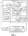
- FIG. 1is a block/flow diagram showing a system/method for shape sensing assistance in a medical procedure in accordance with the present principles
- FIG. 2is a diagram showing a centerline generated in a bifurcated image and for a shape sensed device for comparison in determining if a correct path has been taken in accordance with one embodiment
- FIG. 3is a diagram showing centerlines generated in bifurcated images and shape sensed measurement for a deforming organ for comparison in determining if a correct path has been taken in accordance with another embodiment
- FIG. 4is a block/flow diagram showing a method for shape sensing assistance in a medical procedure in accordance with the present principles.
- device navigationis improved during a procedure by extracting shape-sensing data of a device.
- Tracking technologypermits reconstruction of device shapes along a length of the device.
- the shape-sensed data and tracked positionare then correlated with previously collected images.
- shape sensingthree-dimensional (3D) information of the shape of the device (thus 3D information, e.g., compared to 2D information provided by X-ray or sparse 3D point information from electromagnetic tracking) is available.
- This shape informationis of particular interest in complex systems, such as the airways in lungs, where the shape information can be employed to assist a physician to validate whether a correct path has been selected.
- sensorsare attached to the device and can account for deformations caused by breathing or heart beat so that this motion can be compensated.
- a physicianmay attempt to reach a target with a bronchoscope that is inserted through the airways of the lungs.
- the topology of the airwaysis very complex which often causes physicians to navigate wrong paths. Even if pre-operative imaging data is available for guidance, deformations due to breathing or patient repositioning compromise successful targeting.
- the present principlesemploy shape sensing information obtained from the bronchoscope to reconstruct bronchoscope shapes along whole instrument lengths. This information can be used to overcome current limitations in bronchoscopic interventions by permitting a check between correct and incorrect device shapes which indicate correct or incorrect pathways to a target.
- the present inventionwill be described in terms of medical instruments; however, the teachings of the present invention are much broader and are applicable to any instruments employed in tracking or analyzing complex biological or mechanical systems.
- the present principlesare applicable to internal tracking procedures of biological systems, procedures in all areas of the body such as the lungs, gastro-intestinal tract, excretory organs, blood vessels, etc.
- the elements depicted in the FIGS.may be implemented in various combinations of hardware and software and provide functions which may be combined in a single element or multiple elements.
- processoror “controller” should not be construed to refer exclusively to hardware capable of executing software, and can implicitly include, without limitation, digital signal processor (“DSP”) hardware, read-only memory (“ROM”) for storing software, random access memory (“RAM”), non-volatile storage, etc.
- DSPdigital signal processor
- ROMread-only memory
- RAMrandom access memory
- non-volatile storageetc.
- embodiments of the present inventioncan take the form of a computer program product accessible from a computer-usable or computer-readable storage medium providing program code for use by or in connection with a computer or any instruction execution system.
- a computer-usable or computer readable storage mediumcan be any apparatus that may include, store, communicate, propagate, or transport the program for use by or in connection with the instruction execution system, apparatus, or device.
- the mediumcan be an electronic, magnetic, optical, electromagnetic, infrared, or semiconductor system (or apparatus or device) or a propagation medium.
- Examples of a computer-readable mediuminclude a semiconductor or solid state memory, magnetic tape, a removable computer diskette, a random access memory (RAM), a read-only memory (ROM), a rigid magnetic disk and an optical disk.
- Current examples of optical disksinclude compact disk—read only memory (CD-ROM), compact disk—read/write (CD-R/W) and DVD.
- System 100may include a workstation or console 112 from which a procedure is supervised and managed.
- Workstation 112preferably includes one or more processors 114 and memory 116 for storing programs and applications.
- Memory 116may store an optical sensing module 115 configured to interpret optical feedback signals from a shape sensing device 104 .
- Optical sensing module 115is configured to use the optical signal feedback (and any other feedback, e.g., electromagnetic (EM)) to reconstruct deformations, deflections and other changes associated with a medical device 102 and/or its surrounding region.
- EMelectromagnetic
- the medical device 102may include, e.g., a catheter, a guide wire, an endoscope, a probe, a robot, an electrode, a filter device, a balloon device, or other medical component, etc.
- Workstation 112may include a display 118 for viewing internal images of a subject if an imaging system 110 is employed.
- the imaging system 110may include, e.g., a magnetic resonance imaging (MRI) system, a fluoroscopy system, a computed tomography (CT) system, etc.
- Display 118may also permit a user to interact with the workstation 112 and its components and functions. This is further facilitated by an interface 120 which may include a keyboard, mouse, a joystick or any other peripheral or control to permit user interaction with the workstation 112 .
- Workstation 112includes an optical source 106 to provide optical fibers with light.
- An optical interrogation unit 108is employed to detect light returning from all fibers. This permits the determination of strains or other parameters, which will be used to interpret the shape, orientation, etc. of the interventional device 102 .
- the light signalswill be employed as feedback to make adjustments to access errors and to calibrate the device 102 or system 100 .
- Shape sensing device 104includes one or more fibers which are configured to exploit their geometry for detection and correction/calibration of a shape of the device 102 .
- Optical interrogation unit/module 108works with optical sensing module 115 (e.g., shape determination program) to permit tracking of instrument or device 102 .
- Imaging system 110may be provided for collecting pre-operative imaging data or real-time intra-operative imaging data.
- the pre-operative imagingmay be performed at another facility, location, etc. in advance of any procedure.
- These 3D images 111may be stored in memory 116 .
- device 102is employed to discover or observe a target.
- the targetmay include a lesion, injury site, object or other target.
- shape sensing data from shape sensing device 104is collected and registered with the pre-operative imaging data.
- a registration module 140determines registration positions and registers the shape sensing data with the pre-operative images 111 , which are preferably 3D images.
- the shape sensing datamay include motion data from a heartbeat and/or breathing and motion compensation may be performed to account for the same in the images (e.g., deformations due to breathing can be measured using shape sensing).
- the 3D images 111may include these motion compensated images.
- a pathway determination module 144computes paths and compares rich point data from shape sensing data registered with the motion compensated images to determine whether a correct path was followed.
- the position and the shape of the device 102is compared with the motion compensated images by matched pathways, e.g., in the lungs, with the shape of the device 102 . If lumen walls appearing in the compensated image overlap the shape sensing data positions then a wrong pathway has been taken.
- the system 100provides feedback to the clinician or physician.
- the feedbackmay take a plurality of different forms.
- a visualizationmay be provided on display 118 which provides feedback to the physician that a wrong path was traveled and where the mistake most probably occurred to take corrective measures.
- Another embodimentprovides an audible alarm when an incorrect path has been taken.
- System 100may include a warning mechanism 146 configured to indicate that an incorrect path has been selected.
- the warning mechanism 146may take many forms and may be included in components that are already a part of the system 100 .
- the warning mechanism 148may include one or more of the following features.
- the display 118may be employed to display a location where the incorrect path was selected so that a physician can go back and make corrections.
- a visual (display 118 ) or audible (e.g., a speaker at interface 120 ) indicatormay be generated when an incorrect path is selected.
- the warning mechanism 146may be employed to warn of an imminent incorrect selection to effectively guide the physician during a procedure.
- the device 102includes a bronchoscope, a pathway system 148 being analyzed includes a lung and the shape sensing includes optical shape sensing.
- the pre-operative imagesare obtained by computed tomography (CT) although other imaging methods may be employed.
- CTcomputed tomography
- a global structure of airways of the lungsis extracted from the pre-operative images, and a path that is supposed to be chosen to reach a target is computed by pathway determination module 144 . This path provides information about which path is supposed to be taken by the physician—thus limiting the possibilities where the bronchoscope can be.
- the result of the shape sensing data and the compensated imaging datamay generate centerlines to provide points of comparison.
- FIG. 2depicts a bronchial tree 202 to be navigated during a procedure.
- the tree 202includes many airways 204 that need to be navigated to reach a target 206 .
- two centerlinesare made available.
- One centerline 208has its path measured by the shape sensing component while another centerline 210 is computed from a pre-operative image, such as a CT image, an MRI image, a fluoroscopy image, etc.
- These two centerlines 208 and 210can now be compared.
- a path selected by a physiciancan be verified. This path is modeled by the centerline 208 generated by the shape sensing data.
- Characteristic pointscan be extracted (e.g., points at locations with very high curvature that belong to bifurcations). These points provide reference points to permit better verification as the patient breathes during the intervention. Based on these reference points, information is provided to the physician as to which direction to select at a next branching or bifurcation point. For example, a tip of the bronchoscope or other instrument is tracked to provide its current location so that a virtual rendering can be adapted and assist in decision making for which direction to take at a next decision point (e.g., a trachea bifurcation 212 ). For example, it can be extracted that the tip of the bronchoscope is 3 mm after the trachea. Thus, the virtual image can be adapted with respect to that information.
- a next decision pointe.g., a trachea bifurcation 212
- Having the two centerlines 208 and 210permits motion compensation for local warping between an extracted airway tree and a measured shape. This can be employed to again adapt the virtual rendering or compensate motion locally.
- Local motion or warpingmay be as a result of physical changes such as blood flow, heart beat, breathing, etc., or from other sources, e.g., fusing images from two or more different sources, such as CT/X-Ray fusion, or local warping due to instrument presence. Local warping can also help to verify if the right path has been chosen. For example, bronchial segmentation (and thus the calculated path) can be locally warped according to a deformation field obtained from shape sensing measured centerlines (e.g., before and after deformation). Afterwards, a path can be verified to determine whether the computed path and the measured path match.
- bronchial tree systems 300 and 301are illustratively depicted, respectively for an inhale state and an exhale state.
- a measured path 306 for the exhaleis overlaid on a bronchial tree image 302
- a measured path 308 for the inhaleis overlaid on a bronchial tree image 304 . From the two measurements 306 and 308 , deformation can be computed. Registration of the measure paths 306 and 308 with each of the images 302 and 304 indicates whether the desired path was navigated since the data can be verified multiple times.
- local motion compensationis usually sufficient, as the main interest is usually on an area around the calculated path where the target is located. Thus, e.g., local motion compensation is sufficient in a left main bronchus, while a right main bronchus is not of interest.
- a method for shape sensing assistance in a medical procedureis illustratively shown in accordance with one embodiment.
- a three-dimensional (3D) image of a distributed pathway systemis provided.
- the 3D imagesmay be created by segmenting CT images or images gathered through other systems or technologies (e.g., MRI, X-ray, etc.).
- the imagesmay be processed for motion compensation or other corrections in block 404 .
- the motion compensationmay employ information from shape sensing.
- a shape sensing enabled elongated deviceis introduced into the pathway system.
- the pathway systemmay include a lung, a blood vessel, the heart, etc.
- the elongated devicemay include a catheter, guide wire, bronchoscope, etc.
- the shape sensingis preferably performed using an optical fiber shape sensing system although other shape sensing devices may be employed.
- the elongated deviceis preferably registered with the three-dimensional image. This may be performed using a tracking system (e.g., EM), physical guide posts or other registration methods.
- a shape of the elongated deviceis measured in the pathway system. The measuring of the shape may include measuring a first shape of the elongated device in a first state and a second shape of the elongated device in a deformed state in block 412 . By measuring the shape in different states (e.g., inhale/exhale, etc.), additional data is collected to increase the level of confidence in evaluating the correct pathways being navigated.
- the shape with the three-dimensional imageis compared to determine whether a given path has been selected relative to a target.
- the targetmay include a lesion or other object of the procedure.
- the comparisonmay include first generating geometric representations of the shape(s) and the three-dimensional images. In this way, the geometric representations may be compared.
- the geometric representationsmay include, e.g., centerlines, boundary lines, points of interest, etc.
- a comparison between first and second shapese.g., inhale/exhale
- a comparison between first and second shapese.g., inhale/exhale
- an indication of suchmay be made to the physician.
- the indicationmay include a warning of an imminent incorrect selection, a display of a location where the incorrect path was selected, and/or a visual or audible indication that the incorrect path was selected.
- the processis repeated if necessary for each new decision.
- the procedureis carried out with respect to the target.
Landscapes
- Engineering & Computer Science (AREA)
- Health & Medical Sciences (AREA)
- Life Sciences & Earth Sciences (AREA)
- Physics & Mathematics (AREA)
- Medical Informatics (AREA)
- Software Systems (AREA)
- General Health & Medical Sciences (AREA)
- Theoretical Computer Science (AREA)
- Biophysics (AREA)
- Pathology (AREA)
- Biomedical Technology (AREA)
- Heart & Thoracic Surgery (AREA)
- Radiology & Medical Imaging (AREA)
- Molecular Biology (AREA)
- Surgery (AREA)
- Animal Behavior & Ethology (AREA)
- Nuclear Medicine, Radiotherapy & Molecular Imaging (AREA)
- Public Health (AREA)
- Veterinary Medicine (AREA)
- Radar, Positioning & Navigation (AREA)
- Remote Sensing (AREA)
- Gynecology & Obstetrics (AREA)
- Computer Graphics (AREA)
- Computer Hardware Design (AREA)
- General Engineering & Computer Science (AREA)
- General Physics & Mathematics (AREA)
- Human Computer Interaction (AREA)
- Pulmonology (AREA)
- High Energy & Nuclear Physics (AREA)
- Optics & Photonics (AREA)
- Endoscopes (AREA)
- Apparatus For Radiation Diagnosis (AREA)
Abstract
Description
- a) the word “comprising” does not exclude the presence of other elements or acts than those listed in a given claim;
- b) the word “a” or “an” preceding an element does not exclude the presence of a plurality of such elements;
- c) any reference signs in the claims do not limit their scope;
- d) several “means” may be represented by the same item or hardware or software implemented structure or function; and
- e) no specific sequence of acts is intended to be required unless specifically indicated.
Claims (20)
Priority Applications (1)
| Application Number | Priority Date | Filing Date | Title |
|---|---|---|---|
| US14/008,187US11064955B2 (en) | 2011-03-31 | 2012-03-23 | Shape sensing assisted medical procedure |
Applications Claiming Priority (3)
| Application Number | Priority Date | Filing Date | Title |
|---|---|---|---|
| US201161469988P | 2011-03-31 | 2011-03-31 | |
| PCT/IB2012/051396WO2012131550A1 (en) | 2011-03-31 | 2012-03-23 | Shape sensing assisted medical procedure |
| US14/008,187US11064955B2 (en) | 2011-03-31 | 2012-03-23 | Shape sensing assisted medical procedure |
Publications (2)
| Publication Number | Publication Date |
|---|---|
| US20140039306A1 US20140039306A1 (en) | 2014-02-06 |
| US11064955B2true US11064955B2 (en) | 2021-07-20 |
Family
ID=45932470
Family Applications (1)
| Application Number | Title | Priority Date | Filing Date |
|---|---|---|---|
| US14/008,187Active2033-11-07US11064955B2 (en) | 2011-03-31 | 2012-03-23 | Shape sensing assisted medical procedure |
Country Status (5)
| Country | Link |
|---|---|
| US (1) | US11064955B2 (en) |
| EP (1) | EP2691006B1 (en) |
| JP (1) | JP6195822B2 (en) |
| CN (1) | CN103458764B (en) |
| WO (1) | WO2012131550A1 (en) |
Cited By (1)
| Publication number | Priority date | Publication date | Assignee | Title |
|---|---|---|---|---|
| US20230005135A1 (en)* | 2020-01-14 | 2023-01-05 | Koninklijke Philips N.V. | Image enhancement based on fiber optic shape-sensing |
Families Citing this family (15)
| Publication number | Priority date | Publication date | Assignee | Title |
|---|---|---|---|---|
| IN2014CN02655A (en) | 2011-10-20 | 2015-06-26 | Koninkl Philips Nv | |
| US9183354B2 (en) | 2012-08-15 | 2015-11-10 | Musc Foundation For Research Development | Systems and methods for image guided surgery |
| WO2015110928A1 (en)* | 2014-01-24 | 2015-07-30 | Koninklijke Philips N.V. | Virtual image with optical shape sensing device perspective |
| EP4328856B1 (en)* | 2014-07-28 | 2025-07-02 | Intuitive Surgical Operations, Inc. | Systems and methods for intraoperative segmentation |
| CN104306072B (en)* | 2014-11-07 | 2016-08-31 | 常州朗合医疗器械有限公司 | Medical treatment navigation system and method |
| JP6584518B2 (en) | 2015-02-20 | 2019-10-02 | コーニンクレッカ フィリップス エヌ ヴェKoninklijke Philips N.V. | Medical system, apparatus and method for shape detection |
| JP6824967B2 (en) | 2015-09-18 | 2021-02-03 | オーリス ヘルス インコーポレイテッド | Tubular net navigation |
| JP6976266B2 (en)* | 2016-03-10 | 2021-12-08 | ボディ・ビジョン・メディカル・リミテッドBody Vision Medical Ltd. | Methods and systems for using multi-view pose estimation |
| EP3503834B1 (en) | 2016-08-23 | 2024-06-12 | Intuitive Surgical Operations, Inc. | Systems for monitoring patient motion during a medical procedure |
| JP7167030B2 (en) | 2017-01-03 | 2022-11-08 | コーニンクレッカ フィリップス エヌ ヴェ | MEDICAL NAVIGATION SYSTEM USING SHAPE SENSING DEVICE AND METHOD OF OPERATION |
| WO2018221508A1 (en)* | 2017-06-02 | 2018-12-06 | テルモ株式会社 | Route selection assist system, recording medium for recording route selection assist program, route selection assist method, and diagnosis method |
| US10575907B2 (en)* | 2017-06-21 | 2020-03-03 | Biosense Webster (Israel) Ltd. | Registration with trajectory information with shape sensing |
| US10022192B1 (en) | 2017-06-23 | 2018-07-17 | Auris Health, Inc. | Automatically-initialized robotic systems for navigation of luminal networks |
| WO2020033318A1 (en)* | 2018-08-07 | 2020-02-13 | Auris Health, Inc. | Combining strain-based shape sensing with catheter control |
| CN113614844B (en)* | 2019-03-14 | 2025-09-23 | 皇家飞利浦有限公司 | Dynamic intervention 3D model deformation |
Citations (27)
| Publication number | Priority date | Publication date | Assignee | Title |
|---|---|---|---|---|
| US5577502A (en) | 1995-04-03 | 1996-11-26 | General Electric Company | Imaging of interventional devices during medical procedures |
| US5638819A (en) | 1995-08-29 | 1997-06-17 | Manwaring; Kim H. | Method and apparatus for guiding an instrument to a target |
| US6346940B1 (en) | 1997-02-27 | 2002-02-12 | Kabushiki Kaisha Toshiba | Virtualized endoscope system |
| US20020025017A1 (en)* | 1999-06-17 | 2002-02-28 | Stergios Stergiopoulos | Method for tracing organ motion and removing artifacts for computed tomography imaging systems |
| JP2002306403A (en) | 2001-04-18 | 2002-10-22 | Olympus Optical Co Ltd | Endoscope |
| JP2002345725A (en) | 2001-05-22 | 2002-12-03 | Olympus Optical Co Ltd | Endoscopic system |
| US6580938B1 (en) | 1997-02-25 | 2003-06-17 | Biosense, Inc. | Image-guided thoracic therapy and apparatus therefor |
| US6868195B2 (en) | 2003-02-20 | 2005-03-15 | Fuji Photo Optical Co., Ltd. | Device for detecting three-dimensional shapes of elongated flexible body |
| US20050182319A1 (en)* | 2004-02-17 | 2005-08-18 | Glossop Neil D. | Method and apparatus for registration, verification, and referencing of internal organs |
| US20050251017A1 (en)* | 2004-04-23 | 2005-11-10 | Azar Fred S | System and method registered video endoscopy and virtual endoscopy |
| US20080118135A1 (en)* | 2006-11-10 | 2008-05-22 | Superdimension, Ltd. | Adaptive Navigation Technique For Navigating A Catheter Through A Body Channel Or Cavity |
| US20080183073A1 (en)* | 2007-01-31 | 2008-07-31 | The Penn State Research Foundation | Methods and apparatus for 3d route planning through hollow organs |
| WO2008115375A1 (en) | 2007-03-16 | 2008-09-25 | Luna Innovations Incorporated | Fiber optic position and/or shape sensing based on rayleigh scatter |
| JP2009056239A (en) | 2007-09-03 | 2009-03-19 | Olympus Medical Systems Corp | Endoscope device |
| US20090137952A1 (en) | 2007-08-14 | 2009-05-28 | Ramamurthy Bhaskar S | Robotic instrument systems and methods utilizing optical fiber sensor |
| US20090292166A1 (en) | 2008-05-23 | 2009-11-26 | Olympus Medical Systems Corp. | Medical device |
| WO2010111090A1 (en) | 2009-03-26 | 2010-09-30 | Intuitive Surgical Operations, Inc. | System for providing visual guidance for steering a tip of an endoscopic device towards one or more landmarks and assisting an operator in endoscopic navigation |
| US20100249506A1 (en)* | 2009-03-26 | 2010-09-30 | Intuitive Surgical, Inc. | Method and system for assisting an operator in endoscopic navigation |
| US7930065B2 (en)* | 2005-12-30 | 2011-04-19 | Intuitive Surgical Operations, Inc. | Robotic surgery system including position sensors using fiber bragg gratings |
| US20110319910A1 (en)* | 2007-08-14 | 2011-12-29 | Hansen Medical, Inc. | Methods and devices for controlling a shapeable instrument |
| US20120289777A1 (en)* | 2011-05-13 | 2012-11-15 | Intuitive Surgical Operations, Inc. | Medical system providing dynamic registration of a model of an anatomical structure for image-guided surgery |
| US20140243660A1 (en)* | 2011-10-20 | 2014-08-28 | Koninklilke Philips N.V. | Shape sensing assisted medical procedure |
| US20150265368A1 (en)* | 2014-03-24 | 2015-09-24 | Intuitive Surgical Operations, Inc. | Systems and Methods for Anatomic Motion Compensation |
| US10039473B2 (en)* | 2012-05-14 | 2018-08-07 | Intuitive Surgical Operations, Inc. | Systems and methods for navigation based on ordered sensor records |
| US10085671B2 (en)* | 2012-05-14 | 2018-10-02 | Intuitive Surgical Operations, Inc. | Systems and methods for deformation compensation using shape sensing |
| US10278615B2 (en)* | 2012-08-14 | 2019-05-07 | Intuitive Surgical Operations, Inc. | Systems and methods for registration of multiple vision systems |
| US10575907B2 (en)* | 2017-06-21 | 2020-03-03 | Biosense Webster (Israel) Ltd. | Registration with trajectory information with shape sensing |
Family Cites Families (2)
| Publication number | Priority date | Publication date | Assignee | Title |
|---|---|---|---|---|
| US6468203B2 (en)* | 2000-04-03 | 2002-10-22 | Neoguide Systems, Inc. | Steerable endoscope and improved method of insertion |
| US7697972B2 (en)* | 2002-11-19 | 2010-04-13 | Medtronic Navigation, Inc. | Navigation system for cardiac therapies |
- 2012
- 2012-03-23JPJP2014501755Apatent/JP6195822B2/enactiveActive
- 2012-03-23CNCN201280016342.1Apatent/CN103458764B/enactiveActive
- 2012-03-23USUS14/008,187patent/US11064955B2/enactiveActive
- 2012-03-23EPEP12712765.2Apatent/EP2691006B1/enactiveActive
- 2012-03-23WOPCT/IB2012/051396patent/WO2012131550A1/enactiveApplication Filing
Patent Citations (29)
| Publication number | Priority date | Publication date | Assignee | Title |
|---|---|---|---|---|
| US5577502A (en) | 1995-04-03 | 1996-11-26 | General Electric Company | Imaging of interventional devices during medical procedures |
| US5638819A (en) | 1995-08-29 | 1997-06-17 | Manwaring; Kim H. | Method and apparatus for guiding an instrument to a target |
| US6580938B1 (en) | 1997-02-25 | 2003-06-17 | Biosense, Inc. | Image-guided thoracic therapy and apparatus therefor |
| US6346940B1 (en) | 1997-02-27 | 2002-02-12 | Kabushiki Kaisha Toshiba | Virtualized endoscope system |
| US20020025017A1 (en)* | 1999-06-17 | 2002-02-28 | Stergios Stergiopoulos | Method for tracing organ motion and removing artifacts for computed tomography imaging systems |
| JP2002306403A (en) | 2001-04-18 | 2002-10-22 | Olympus Optical Co Ltd | Endoscope |
| JP2002345725A (en) | 2001-05-22 | 2002-12-03 | Olympus Optical Co Ltd | Endoscopic system |
| US6868195B2 (en) | 2003-02-20 | 2005-03-15 | Fuji Photo Optical Co., Ltd. | Device for detecting three-dimensional shapes of elongated flexible body |
| US20050182319A1 (en)* | 2004-02-17 | 2005-08-18 | Glossop Neil D. | Method and apparatus for registration, verification, and referencing of internal organs |
| US10582879B2 (en)* | 2004-02-17 | 2020-03-10 | Philips Electronics Ltd | Method and apparatus for registration, verification and referencing of internal organs |
| US20050251017A1 (en)* | 2004-04-23 | 2005-11-10 | Azar Fred S | System and method registered video endoscopy and virtual endoscopy |
| US7930065B2 (en)* | 2005-12-30 | 2011-04-19 | Intuitive Surgical Operations, Inc. | Robotic surgery system including position sensors using fiber bragg gratings |
| US20080118135A1 (en)* | 2006-11-10 | 2008-05-22 | Superdimension, Ltd. | Adaptive Navigation Technique For Navigating A Catheter Through A Body Channel Or Cavity |
| US20080183073A1 (en)* | 2007-01-31 | 2008-07-31 | The Penn State Research Foundation | Methods and apparatus for 3d route planning through hollow organs |
| WO2008115375A1 (en) | 2007-03-16 | 2008-09-25 | Luna Innovations Incorporated | Fiber optic position and/or shape sensing based on rayleigh scatter |
| US20090137952A1 (en) | 2007-08-14 | 2009-05-28 | Ramamurthy Bhaskar S | Robotic instrument systems and methods utilizing optical fiber sensor |
| US20110319910A1 (en)* | 2007-08-14 | 2011-12-29 | Hansen Medical, Inc. | Methods and devices for controlling a shapeable instrument |
| JP2009056239A (en) | 2007-09-03 | 2009-03-19 | Olympus Medical Systems Corp | Endoscope device |
| US20090292166A1 (en) | 2008-05-23 | 2009-11-26 | Olympus Medical Systems Corp. | Medical device |
| WO2010111090A1 (en) | 2009-03-26 | 2010-09-30 | Intuitive Surgical Operations, Inc. | System for providing visual guidance for steering a tip of an endoscopic device towards one or more landmarks and assisting an operator in endoscopic navigation |
| US20100249506A1 (en)* | 2009-03-26 | 2010-09-30 | Intuitive Surgical, Inc. | Method and system for assisting an operator in endoscopic navigation |
| US20120289777A1 (en)* | 2011-05-13 | 2012-11-15 | Intuitive Surgical Operations, Inc. | Medical system providing dynamic registration of a model of an anatomical structure for image-guided surgery |
| US20140243660A1 (en)* | 2011-10-20 | 2014-08-28 | Koninklilke Philips N.V. | Shape sensing assisted medical procedure |
| US20190008413A1 (en)* | 2012-05-14 | 2019-01-10 | Intuitive Surgical Operations,Inc. | Systems and methods for deformation compensation using shape sensing |
| US10085671B2 (en)* | 2012-05-14 | 2018-10-02 | Intuitive Surgical Operations, Inc. | Systems and methods for deformation compensation using shape sensing |
| US10039473B2 (en)* | 2012-05-14 | 2018-08-07 | Intuitive Surgical Operations, Inc. | Systems and methods for navigation based on ordered sensor records |
| US10278615B2 (en)* | 2012-08-14 | 2019-05-07 | Intuitive Surgical Operations, Inc. | Systems and methods for registration of multiple vision systems |
| US20150265368A1 (en)* | 2014-03-24 | 2015-09-24 | Intuitive Surgical Operations, Inc. | Systems and Methods for Anatomic Motion Compensation |
| US10575907B2 (en)* | 2017-06-21 | 2020-03-03 | Biosense Webster (Israel) Ltd. | Registration with trajectory information with shape sensing |
Cited By (1)
| Publication number | Priority date | Publication date | Assignee | Title |
|---|---|---|---|---|
| US20230005135A1 (en)* | 2020-01-14 | 2023-01-05 | Koninklijke Philips N.V. | Image enhancement based on fiber optic shape-sensing |
Also Published As
| Publication number | Publication date |
|---|---|
| US20140039306A1 (en) | 2014-02-06 |
| JP6195822B2 (en) | 2017-09-13 |
| JP2014509546A (en) | 2014-04-21 |
| CN103458764B (en) | 2017-05-03 |
| EP2691006A1 (en) | 2014-02-05 |
| CN103458764A (en) | 2013-12-18 |
| EP2691006B1 (en) | 2019-06-05 |
| WO2012131550A1 (en) | 2012-10-04 |
Similar Documents
| Publication | Publication Date | Title |
|---|---|---|
| US11064955B2 (en) | Shape sensing assisted medical procedure | |
| US11690527B2 (en) | Apparatus and method for four dimensional soft tissue navigation in endoscopic applications | |
| US11033181B2 (en) | System and method for tumor motion simulation and motion compensation using tracked bronchoscopy | |
| US11109775B2 (en) | Shape sensing assisted medical procedure | |
| JP7154832B2 (en) | Improving registration by orbital information with shape estimation | |
| CN107871531B (en) | Fracture assessment and surgical intervention planning | |
| CN107865692B (en) | System and method for detecting pleural invasion in surgical and interventional planning | |
| EP3607906A1 (en) | Identification and notification of tool displacement during medical procedure | |
| Gergel et al. | An electromagnetic navigation system for transbronchial interventions with a novel approach to respiratory motion compensation | |
| JP2019531113A (en) | How to use soft point features to predict respiratory cycle and improve end alignment | |
| CN117412724A (en) | System and method for evaluating breath hold during intra-procedural imaging | |
| EP3454293B1 (en) | Method and apparatus for enhancement of bronchial airways representations using vascular morphology | |
| US20240407741A1 (en) | System and method for updating registration and localization during surgical navigation | |
| WO2024252227A1 (en) | System and method for updating registration and localization during surgical navigation |
Legal Events
| Date | Code | Title | Description |
|---|---|---|---|
| AS | Assignment | Owner name:KONINKLIJKE PHILIPS N.V., NETHERLANDS Free format text:ASSIGNMENT OF ASSIGNORS INTEREST;ASSIGNORS:KLINDER, TOBIAS;MANZKE, ROBERT;CHAN, RAYMOND;SIGNING DATES FROM 20120326 TO 20120707;REEL/FRAME:031299/0308 | |
| STPP | Information on status: patent application and granting procedure in general | Free format text:NON FINAL ACTION MAILED | |
| STPP | Information on status: patent application and granting procedure in general | Free format text:RESPONSE TO NON-FINAL OFFICE ACTION ENTERED AND FORWARDED TO EXAMINER | |
| STPP | Information on status: patent application and granting procedure in general | Free format text:FINAL REJECTION MAILED | |
| STPP | Information on status: patent application and granting procedure in general | Free format text:RESPONSE AFTER FINAL ACTION FORWARDED TO EXAMINER | |
| STPP | Information on status: patent application and granting procedure in general | Free format text:ADVISORY ACTION MAILED | |
| STPP | Information on status: patent application and granting procedure in general | Free format text:DOCKETED NEW CASE - READY FOR EXAMINATION | |
| STPP | Information on status: patent application and granting procedure in general | Free format text:NON FINAL ACTION MAILED | |
| STPP | Information on status: patent application and granting procedure in general | Free format text:FINAL REJECTION MAILED | |
| STPP | Information on status: patent application and granting procedure in general | Free format text:RESPONSE AFTER FINAL ACTION FORWARDED TO EXAMINER | |
| STPP | Information on status: patent application and granting procedure in general | Free format text:NOTICE OF ALLOWANCE MAILED -- APPLICATION RECEIVED IN OFFICE OF PUBLICATIONS | |
| STPP | Information on status: patent application and granting procedure in general | Free format text:PUBLICATIONS -- ISSUE FEE PAYMENT RECEIVED | |
| STPP | Information on status: patent application and granting procedure in general | Free format text:PUBLICATIONS -- ISSUE FEE PAYMENT VERIFIED | |
| STCF | Information on status: patent grant | Free format text:PATENTED CASE | |
| MAFP | Maintenance fee payment | Free format text:PAYMENT OF MAINTENANCE FEE, 4TH YEAR, LARGE ENTITY (ORIGINAL EVENT CODE: M1551); ENTITY STATUS OF PATENT OWNER: LARGE ENTITY Year of fee payment:4 |