US11064817B2 - Merchandiser and methods relating to same - Google Patents
Merchandiser and methods relating to sameDownload PDFInfo
- Publication number
- US11064817B2 US11064817B2US15/747,052US201615747052AUS11064817B2US 11064817 B2US11064817 B2US 11064817B2US 201615747052 AUS201615747052 AUS 201615747052AUS 11064817 B2US11064817 B2US 11064817B2
- Authority
- US
- United States
- Prior art keywords
- tray
- product display
- sidewall
- merchandiser
- product
- Prior art date
- Legal status (The legal status is an assumption and is not a legal conclusion. Google has not performed a legal analysis and makes no representation as to the accuracy of the status listed.)
- Active, expires
Links
Images


Classifications
- A—HUMAN NECESSITIES
- A47—FURNITURE; DOMESTIC ARTICLES OR APPLIANCES; COFFEE MILLS; SPICE MILLS; SUCTION CLEANERS IN GENERAL
- A47F—SPECIAL FURNITURE, FITTINGS, OR ACCESSORIES FOR SHOPS, STOREHOUSES, BARS, RESTAURANTS OR THE LIKE; PAYING COUNTERS
- A47F1/00—Racks for dispensing merchandise; Containers for dispensing merchandise
- A47F1/04—Racks or containers with arrangements for dispensing articles, e.g. by means of gravity or springs
- A47F1/12—Racks or containers with arrangements for dispensing articles, e.g. by means of gravity or springs dispensing from the side of an approximately horizontal stack
- A47F1/125—Racks or containers with arrangements for dispensing articles, e.g. by means of gravity or springs dispensing from the side of an approximately horizontal stack with an article-pushing device
- A47F1/126—Racks or containers with arrangements for dispensing articles, e.g. by means of gravity or springs dispensing from the side of an approximately horizontal stack with an article-pushing device the pushing device being urged by spring means
- A—HUMAN NECESSITIES
- A47—FURNITURE; DOMESTIC ARTICLES OR APPLIANCES; COFFEE MILLS; SPICE MILLS; SUCTION CLEANERS IN GENERAL
- A47F—SPECIAL FURNITURE, FITTINGS, OR ACCESSORIES FOR SHOPS, STOREHOUSES, BARS, RESTAURANTS OR THE LIKE; PAYING COUNTERS
- A47F1/00—Racks for dispensing merchandise; Containers for dispensing merchandise
- A47F1/04—Racks or containers with arrangements for dispensing articles, e.g. by means of gravity or springs
- A47F1/12—Racks or containers with arrangements for dispensing articles, e.g. by means of gravity or springs dispensing from the side of an approximately horizontal stack
- A47F1/125—Racks or containers with arrangements for dispensing articles, e.g. by means of gravity or springs dispensing from the side of an approximately horizontal stack with an article-pushing device
- A—HUMAN NECESSITIES
- A47—FURNITURE; DOMESTIC ARTICLES OR APPLIANCES; COFFEE MILLS; SPICE MILLS; SUCTION CLEANERS IN GENERAL
- A47F—SPECIAL FURNITURE, FITTINGS, OR ACCESSORIES FOR SHOPS, STOREHOUSES, BARS, RESTAURANTS OR THE LIKE; PAYING COUNTERS
- A47F5/00—Show stands, hangers, or shelves characterised by their constructional features
- A47F5/0081—Show stands or display racks with movable parts
- A47F5/0093—Show stands or display racks with movable parts movable in a substantially horizontal direction
Definitions
- This inventionrelates generally to product displays and, more particularly, to merchandisers for front-facing product merchandise for displaying and dispensing product to consumers.
- Product displayssuch as merchandisers, are frequently used in retail environments to display products for sale. It is advantageous for these product displays to be configured to provide consumers easy access to the displayed product as well as facilitate easy reloading by store employees. In addition to ease of use considerations, manufacturers of product displays seek to minimize materials and manufacturing costs associated with the product displays.
- tray or drawer-type merchandisersthat pull out like a drawer to assist store associates in stocking/restocking the merchandiser often require intricate structures that are expensive to manufacture, hard to assemble, and often require operation of inconveniently located release mechanisms to get the tray or drawer to slide out from the display for stocking or restocking purposes.
- tray or drawer type merchandisersrequire the displayed product to be pressed against pushers during stocking/restocking which can make the merchandiser harder to stock/restock and can cause damage to the product being stocked/restocked depending on how much force is exerted against the product between the person stocking/restocking the displayed product and the pushers of the merchandiser.
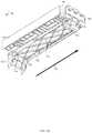
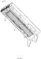
- FIG. 1Ais a perspective view of a product display merchandiser according to some embodiments of the inventive subject matter taken from below and in front of the merchandiser (or the lower right front of the unit) and illustrating an exemplary baseless design with the left side member or wing in a first, retracted position and the right side member or wing in a second, extended position.
- FIG. 1Bis an alternate perspective view of the product display merchandiser of FIG. 1 , taken from above and in front of the merchandiser (or the upper left front of the unit).
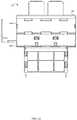
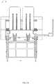
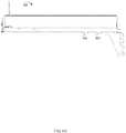
- FIGS. 1C, 1D, and 1Eare front elevation, rear elevation, and left side elevation views, respectively, of the product display merchandiser of FIGS. 1A-1B , the right side elevation view being a mirror image of the left side elevation view.
- FIGS. 1F and 1Gare top and bottom views, respectively, of the product display merchandiser of FIGS. 1A-E illustrating the merchandiser with the tray in a first, retracted position.
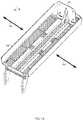
- FIGS. 1H, 1I, 1J, and 1Kare alternate perspective, left side elevation, top view, and bottom view, respectively, of the product display merchandiser of FIGS. 1A-1G illustrating the merchandiser with the tray in a second, extended position.
- FIGS. 1L and 1Mare perspective views of an exemplary removable divider illustrating, in FIG. 1L , one form of mating structure that may be used to mate the divider to the merchandiser unit, and illustrating in FIG. 1M , an exemplary manner in which the removable divider may be stored on the merchandiser for future use.
- FIG. 2is a perspective view of an alternate product display merchandiser in accordance with aspects of the invention taken from above the rear right corner of the merchandiser and illustrating the merchandiser with an alternate form of mounting bracket intended for use with bar mounted systems rather than grid systems, including alternate side members or wings for larger product and an exemplary pusher attachment accessory (note: while a bar mounting bracket and a grid mounting bracket are shown for comparison purposes, it should be understood that the merchandiser would be equipped with either two bar mounting brackets or two grid mounting brackets, rather than a combination of either).
- FIG. 3is a top view of an alternate product display merchandiser in accordance with embodiments of the invention illustrating an optional front and/or rear stabilizer member connected to the mounting brackets for stabilizing same.
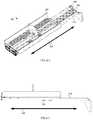
- FIG. 4Ais a perspective view of another product display merchandiser in accordance with embodiments of the invention taken from above and behind the merchandiser (or the right rear corner of the unit) and illustrating an alternate baseless tray or drawer type merchandiser design with an alternate manner for adjusting the side members or wings of the unit to adjust width of the merchandiser and an alternate means for securing the tray in the first, retracted position so as to avoid inadvertent movement of the merchandiser to the second, extended position (note: the left side member or wing is adjusted to a wider position than the right side member or wing simply to show that the merchandiser does not have to be setup symmetrically if desired).
- FIG. 4Bis a perspective view of the merchandiser of FIG. 4A taken from below and in front of the merchandiser (or the lower left front corner of the unit) and illustrating the alternate rear stabilizer and adjustable width mechanism of the merchandiser.
- FIG. 4C-Dare front elevation and rear elevation views of the product display merchandiser of FIGS. 4A-B again illustrating how the width of the left side member or wing has been adjusted more than the right (or the left side member has been displaced further from the center of the merchandiser or from a central axis running through the center of the merchandiser than the right side member is from the central axis).
- FIGS. 4E, 4F, and 4Gare left side elevation, top, and bottom views, respectively of the product display merchandiser of FIGS. 4A-D illustrating the merchandiser in the same first, retracted or closed position the merchandiser is illustrated in for FIGS. 4A-D .
- FIGS. 4H and 4Iare alternate perspective and left side elevation views, respectively, of the merchandiser of FIGS. 4A-G illustrating the merchandiser in a second, extended or open position which a store associate may place the merchandiser in for stocking or restocking purposes.
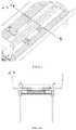
- FIG. 4Jis an enlarged, partial perspective view of the tray portion of the merchandiser of FIGS. 4A-4I illustrating how the width of the side members may be adjusted and how a user may keep track of same (again noting the left side member is illustrated as being adjusted to a wider position than the right side member).
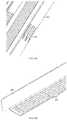
- FIG. 4Kis a cross-section of the merchandiser of FIG. 4J taken along line 4 K- 4 K.
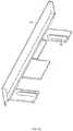
- FIG. 4Lis a partial perspective view of only a portion of the merchandiser of FIGS. 4A-4K illustrating the support brackets, first and second stabilizing members and a baffle structure for directing air from a rear of the merchandiser toward the front of the merchandiser and, thus, from the rear of any open-air refrigeration unit the merchandiser may be installed in toward the front of the open air refrigeration unit in order to assist in keeping product within the refrigeration unit at a generally uniform temperature.
- the front stabilizeralso has a first mating structure for engaging a portion of the remainder of the merchandiser unit in order to retain the unit in the retracted position and/or prevent inadvertent movement of the merchandising unit to the second, extended position.
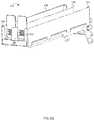
- FIG. 4Mis a partial perspective view of only a portion of the merchandiser of FIGS. 4A-4K illustrating second mating structures for engaging with the first mating structures of the merchandiser portions of FIG. 4L in order to retain the merchandising unit in the retracted position and/or to prevent inadvertent movement of the merchandising unit to the second, extended position.
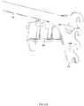
- FIGS. 4N, 4O, and 4Pare partial perspective views of the stabilizer located at the rear portion of the merchandiser of FIG. 4L illustrating from the front ( FIG. 4N ) and rear ( FIG. 4O ) how the baffle is inserted into or nested within the rear stabilizer and how the rear stabilizer is connected to the side members, and further illustrating in FIG. 4P what the rear stabilizer looks like when removed from the merchandiser.
- FIGS. 4Q and 4Rare partial perspective views of the tray and a side member, respectively, depicted one exemplary mechanism for securing a side member to the tray.
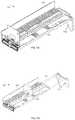
- FIG. 5Ais an exploded view of another product display merchandiser in accordance with embodiments of the inventive subject matter having an alternate manner for adjusting the side member or wings of the unit to adjust width of the merchandiser.
- FIGS. 5B and 5Care perspective views of the side members or wings of the product display merchandiser depicted in FIG. 5A .
- FIG. 5Dis a perspective view of a tray of the product display merchandiser depicted in FIG. 5A .
- FIG. 5Eis a perspective view of a product display merchandiser with a lens removed.
- FIG. 6Ais a partial perspective view of another product display merchandiser in accordance with embodiments of the inventive subject matter having a mechanism to securely attach a bracket engagement member to a rear stabilizer
- FIG. 6Bis an exploded view of the bracket engagement member and rear stabilizer of the product display merchandiser depicted in FIG. 6A .
- FIG. 6Cis an exploded view of the bracket engagement member of the product display merchandiser depicted in FIG. 6A .
- FIG. 6Dis an exploded view of the rear stabilizer of the product display merchandiser depicted in FIG. 6A .
- FIG. 7Ais a perspective view of another product display merchandiser in accordance with embodiments of the inventive subject matter in which one or more of the product display merchandiser's sidewalls or wings is removable.
- product display merchandiserscan be arranged in a linear fashion and a sidewall or wing of an adjacent product display merchandiser can provide support for a product displayed in the product display merchandiser.
- FIG. 7Bis a perspective view of the product display merchandiser of FIG. 7A in an extended position in which product can be loaded onto the product display merchandiser from the side.
- FIGS. 1A-1Mand the associated text, generally depict and describe a first embodiment of a product display, wherein the product display has a baseless design, FIG. 2 and its associated text generally depict a second embodiment, FIG. 3 and its associated text generally depict a third embodiment, FIGS.
- FIGS. 4A-Pgenerally depict and describe a fourth embodiment of a product display merchandiser, wherein the product display merchandiser has an adjustable width and a unique stabilizing structure
- FIGS. 5A-5Egenerally depict and describe a fifth embodiment of a product display merchandiser, wherein the product display merchandiser has an alternate mechanism for adjusting the position of, and securing, the sidewalls or wings and alternate structures for retaining displayed product in the merchandiser when the lens is removed
- FIGS. 6A-6Bgenerally depict and describe a sixth embodiment of a product display merchandiser, wherein the product display merchandiser includes a mechanism to securely attach a bracket engagement member to a rear stabilizer, and FIGS.
- FIG. 7A-7Bgenerally depict and describe a seventh embodiment of a product display merchandiser, wherein the product display merchandiser includes one or more removable sidewalls or wings for use in unison with one or more other product display merchandisers.
- the product display merchandiserincludes one or more removable sidewalls or wings for use in unison with one or more other product display merchandisers.
- FIGS. 1A-1Millustrate an exemplary embodiment of a product display merchandiser 100 , according to some forms of the inventive subject matter.
- the product display merchandiser 100includes a tray 102 for holding a product to be displayed.
- the tray 102is supported underneath by arms, support members, brackets, or “blades” 116 .
- the arms 116include bracket engagement members 112 that attach to a rear support member (not shown), such as a vertical upright of a conventional gondola or other store shelving system.
- the rear support membercan be any suitable support member such as conventional grid-type systems, bar type systems, shelves, etc.
- the product display merchandiser 100can also have one or more stabilizers positioned in various locations on the product display merchandiser 100 . For example, FIG.
- the product display merchandiser 100can include a stabilizer, in addition to or in lieu of the stabilizer 114 , near the front of the product display merchandiser 100 .
- the stabilizer 114(as well as any other stabilizers) can be sized so as to accommodate trays of multiple dimensions.
- the product display merchandiser 100can also include a lens 106 for holding and displaying signage, preventing product from falling out of the tray 102 , etc.
- a lenscan be formed from any suitable material and in any suitable manner.
- the lenscan be extruded or injection molded plastic. Additionally, in one form, the lens can have perforations which allow for easy snap-off type custom-sizing of the lens.
- the product display merchandiser 100has multiple positions.
- the product display merchandiser 100can have a closed position (best shown in FIGS. 1A-1B, and 1E-1G ) for presenting product and an open position (best shown in FIGS. 1H-1K ) for restocking product.
- a closed positiona majority of the tray 102 is positioned over top of the arms 116 .
- the open positionthe majority of the tray 102 is not positioned over top of the arms 116 .
- the tray 102travels along the arms 116 from the closed position to the open position in a direction indicated by arrow 126 .
- the tray 102includes tracks 120 through which the arms 116 extend.
- the tracks 120can take any suitable form.
- the tracks 120can comprise a number of individual pieces protruding from the tray 102 , a continuous or semi-continuous channel running along the tray 102 , etc. Additionally the tracks 120 (and/or arms 116 ) can include ball bearings or any other suitable friction-reducing mechanism.
- the product display merchandiser 100includes a mechanism that resists movement of the tray 102 between the open and closed positions. Such a mechanism can prevent the tray 102 from moving from the closed position to the open position unintentionally.
- the product display merchandiser 100can include a handle 110 (also seen in FIG. 1K ) with first engagement members 108 .
- the arms 116can include second engagement members 104 that are complimentary to the first engagement members 108 .
- Such first engagement members 108 and second engagement members 104are well-depicted in FIG. 1E .
- the engagement membersare engaged when the tray 102 is in the closed position. Such engagement resists and/or prevents movement of the tray 102 to the open position.
- FIG. 1EThe engagement members are engaged when the tray 102 is in the closed position. Such engagement resists and/or prevents movement of the tray 102 to the open position.
- operation of the handle 110disengages the engagement members.
- Such disengagementpermits movement of the tray 102 from the closed position to the open position.
- the first engagement members 108disengage from the second engagement members 104 when the handle 110 is displaced in a direction parallel to the movement of the tray 102 across the arms 116 (i.e., in the direction of arrow 126 ).
- movement of the handle away from the bracket engagement members 112disengages the first engagement members 108 from the second engagement members 104 .
- the handle 110may displace in a somewhat rotational manner.
- the handle 110can be affixed to the tray 102 near a leading edge of the tray (i.e., a portion of the tray opposite the bracket engagement members 112 ).
- the handle 110is operated from an end of the handle 110 opposite a side of the handle 110 affixed to the tray 102 .
- the handle 110displaces in a somewhat rotational direction that, for purposes of this specification, can be considered to have a displacement in a direction parallel to the motion of the tray 102 and in a direction perpendicular to the motion of the tray 102 .
- the product display merchandiser 100can include a mechanism that prevents the tray 102 from moving from the open position to the closed position during restocking.
- the arms 116 and the tracks 120can include complimentary engagement members that engage when the tray 102 is in the open position. Such engagement members can provide mechanical resistance which must be overcome to move the tray 102 from the open position to the closed position.
- FIG. 1Idepicts a product display merchandiser 100 with arms having an arm engagement member 144 which engages a track engagement member 136 . When the tray 102 is in the open position, the track engagement member 136 engages the arm engagement member 144 and provides resistance against the tray 102 moving from the open position to the closed position.
- such resistanceis physical and is overcome by force being exerted on the tray 102 in a direct of the closed position.
- the product display merchandiser 100includes a tray 102 and arms 116 .
- the tray 102includes tracks 120 through which the arms 116 extend.
- the tray 102displaces along the arms 116 .
- the arms 116can include bracket engagement members 112 configured to mount to a rear support member (not shown).
- FIG. 1Bdepicts the product display merchandiser 100 configured with bracket engagement members 112 to mount to a rear stabilizer, in some embodiments, the product display merchandiser 100 can be configured to be supported by, attach to, and/or rest on a shelf.
- the tray 102includes a right sidewall 124 and a left sidewall 126 (also referred to as a “side members” or “wings”), as well as a lens 106 .
- a right sidewall 124 and a left sidewall 126also referred to as a “side members” or “wings”
- a lens 106a lens 106 .
- either (or both) of the right sidewall 124 and the left sidewall 126are extendable to accommodate product of varying dimensions.
- the tray 102 of FIG. 1Bis depicted with the right sidewall 124 extended. In one form, the right sidewall 124 and left sidewall 126 are incrementally extendable.
- the right sidewall 124 and the left sidewall 126can be individually extendable or mechanically coupled in such a way that extension of one of the right sidewall 124 and the left sidewall 126 cause extension of the other of the right sidewall 124 and the left sidewall 126 .
- some embodiments of the product display merchandiser 100include a removable divider 130 .
- the removable product divider 130is shown in greater detail in FIG. 1L .
- the removable divider 130can attach to the product display merchandiser 100 in any suitable manner.
- the removable divider 130can include divider protrusions 148 that mate with slots 118 on the tray 102 (as shown in FIG. 1G ), slots which mate with protrusions on the tray 102 , a bar that mates with a track on the tray 102 , etc.
- the removable divider 130is mountable at multiple locations of varying distance from the right sidewall 124 and the left sidewall 126 .
- the product display merchandiser 100When removed, the product display merchandiser 100 preferably includes a storage space for the removable divider 130 .
- FIG. 1Mdepicts one example by which the removable divider 130 can be stored onboard the product display merchandiser 100 .
- the tray 102includes a recess on a bottom side of the tray 102 configured to accommodate and store the removable divider 130 .
- the tray 102can include clips 150 (or other suitable connectors) which hold the removable divider 130 in a stored position on the product display merchandiser 100 .
- a divider 142(whether or not removable) can take the form of a “T-shape.”
- a horizontal portion of such divider 142can form a product support surface 140 .
- This product support surface 140can support a portion of product displayed in the product display merchandiser and a second product support surface 138 located on the sidewall can support another portion of the product displayed in the product display merchandiser 100 .
- the tray 102also includes pushers 122 .
- the pushers 122act to urge product toward the front of the tray 102 (i.e., front face product) making the product easier to access.
- FIG. 1Bdepicts the tray 102 as including pushers 122 , some embodiments of the inventive subject matter do not include pushers 122 to urge product to the front of the tray.
- the product display merchandiser 100may be configured to incline, or mount on an incline, in a manner in which gravitational force is employed to urge product to the front of the tray 102 .
- FIG. 1Bdepicts a product display merchandiser 100 including two pushers 122
- the pushers 122generally comprise a vertical member and a biasing mechanism.
- the pushers 122can employ any suitable biasing mechanism, such as a spring, a counterweight, a pulley system, etc.
- the pushers 122include engagement members (e.g., clips, latches, detents, etc.) that engage with complimentary engagement members located on the tray 102 , tracks 120 , and/or arms 116 .
- the engagement members and the complimentary engagement membersact to maintain the pushers 122 in a restocking position when the tray 102 is in an open position. Maintaining the pushers 122 in the restocking position not only makes restocking easier but also helps prevent product from being damaged during the restocking process. In some embodiments, the pushers 122 are maintained at a backmost portion of the tray 102 during restocking. In some embodiments, the engagement members and the complimentary engagement members automatically disengage when the tray 102 is moved from the open position to the closed position.
- the tray 102 , tracks 120 , and/or arms 116can include disengagement members that cause disengagement of the engagement members from the complimentary engagement members. FIGS.
- FIG. 1Jdepicts two engagement members 146 coupled to the pushers 122 .
- FIG. 1Jdepicts an embodiment including two pushers 122 and two engagement members 146 , it is not necessary that there be a one-to-one correspondence between the pushers 122 and engagement members 146 .
- the two engagement members 146act (in concert with the complimentary engagement members) to maintain the pushers 122 in the restocking position when the tray 102 is in the open position.
- FIGS. 1D and 1Hdepict a product display merchandiser 100 having disengagement members 132 .
- the disengagement members 132are linearly aligned with the pushers 122 and correspond one-to-one with the pushers 122 , although embodiments exist that do not have either of these features (e.g., one form may have one disengagement member 132 and three pushers 122 ).
- the disengagement members 132act to disengage the engagement members 146 and the complimentary engagement members when the tray 102 is moved from the open position to the closed position. Such action by the disengagement members 132 cause the pushers 122 to be automatically removed from the restocking position.
- the disengagement members 132are protrusions that physically contact one or more of the engagement members and the complimentary engagement members to force disengagement of the engagement members and the complimentary engagement members.
- FIG. 1Cis a front view of a product display merchandiser 100 , according to some embodiments of the inventive subject matter.
- the product display merchandiser 100includes a lens 106 .
- the lens 106can hold and/or display signage, prevent product from falling out of the tray 100 , etc.
- Such a lenscan be formed from any suitable material and in any suitable manner.
- the lenscan be extruded or injection molded plastic.
- the lenscan have perforations which allow for easy snap-off type custom-sizing of the lens.
- the lens 106can have multiple display sections or channels.
- the lens 106may have a first display portion 106 A and a second lens portion 106 B.
- FIG. 1Cdepicts lens 106 as having the second display portion 106 B arranged above the first display portion 106 A, many other configuration exist.
- the lens 106may have left and right display sections, or any other combination of two or more display sections.
- FIG. 1the product tray is referred to generally by reference number 102
- the product trayis referred to as 202 , 302 , and 402 , in FIG. 2 , FIG. 3 , and FIG. 4 , respectively.
- FIGS. 1A-1Mdepict a first embodiment of a product display merchandiser 100
- FIG. 2depicts a second embodiment of a product display merchandiser 200 , according to some embodiments of the inventive subject matter.
- the product display merchandiser 200includes sidewalls 228 , pushers 222 A and 222 B, bracket engagement members 212 , and a pusher attachment 252 .
- the pusher attachment 252attaches to the pusher 222 B to expand the surface area of the pusher 222 B.
- Additional types of pusher attachmentsexist. For example, pusher attachments can be designed for specific products, to minimize the surface area of the contact point with a product, to extend the depth of the pusher, etc. Additionally, FIG.
- FIG. 2depicts a bracket engagement member 212 that is configured to engage a bar mounted system (not shown). Additionally, FIG. 2 depicts an embodiment of a product display merchandiser in which a horizontal portion of the sidewall 228 (i.e., the product support 238 portion of the sidewall) is roughly equal in area to a vertical portion of the sidewall 228 .
- FIG. 2depicts a second embodiment of a product display merchandiser
- FIG. 3depicts a third embodiment of a product display merchandiser 300 , according to some embodiments of the inventive subject matter.
- the product display merchandiser 300includes a tray 302 that is slidable along arms 316 .
- the tray 302includes tracks 320 disposed on the bottom side of the tray 302 .
- the arms 316are seated in the tracks 320 .
- the tray 302moves in a direction as indicated by arrow 326 from an open position (shown) to a closed position (not shown). When in the open position, a void (or unobstructed opening) 358 is revealed (i.e., the product display merchandiser 300 has a baseless design).
- the void 358is bounded on a left side and a right side by arms 316 , on a front side by front stabilizer 354 , and on a rear side by rear stabilizer 356 .
- the trayalso includes pushers 322 A and 322 B which are movable within in the tray 302 and a handle 310 .
- the handle 310is operable to disengage engagement members so as to allow the tray 302 to be moved from the closed position to the open position.
- the tray 302includes a divider 330 / 342 .
- the divider 330 / 342can be fixed to the tray 302 or removably attached to the tray 302 .
- FIG. 3depicts a third embodiment of a product display merchandiser
- FIGS. 4A-4Rdepict a fourth embodiment of a product display merchandiser 400 having an extendable tray width.
- FIG. 4Ais an upper perspective view of a fourth embodiment of the product display merchandiser 400 having adjustable side members 428 , according to some embodiments of the inventive subject matter.
- the product display merchandiser 400 depicted in FIG. 4Ahas one pusher 422 and movable sidewalls 428 .
- the sidewalls 428are extendable from the tray in directions indicated by arrows 426 . Extension of the sidewalls 428 allows for the tray width to be adjusted.
- the trayalso includes first mating members 476 (best shown in FIG. 4Q ) into which corresponding protrusions 478 (best shown in FIG. 4R ) can seat to secure the sidewalls 428 in an extended position.
- a horizontal portion of the sidewalls 428includes second mating members (e.g., protrusions 478 extending from the horizontal portion of the sidewalls 428 , as depicted in FIG. 4R ) which fit into the first mating members 476 .
- the second mating members“snapfit” into the first mating members 476 .
- a personcan lift an edge of one of the sidewalls 428 to disengage the second mating members from the first mating members 428 .
- the sidewalls 428are secured to the product display by one or more housing members or cords. Such housing members or cords can prevent the sidewalls 428 from becoming completely detached from the product display merchandiser 400 when disengaged.
- each of the sidewalls 428are independently movable. For example, a first of the two sidewalls 428 can be moved, and then a second of the two sidewalls 428 can be moved independently of the first.
- the sidewalls 428can be coupled in such a manner that when one of the two sidewalls 428 is moved, the other of the two sidewalls 428 moves in a corresponding manner.
- the product display merchandiser 400includes linear guides 476 , depicted in FIGS. 4J and 4K .
- the linear guides 476help ensure that the sidewalls 428 travel linearly with respect to the product display merchandiser 400 when moved between positions.
- the linear guides 476are protrusions that are seated in recess disposed in a horizontal portion of the sidewalls 428 .
- FIG. 4Qdepicts the first mating members 476 as incrementally spaced slots
- any suitable mechanism for securing the sidewalls in an extended positionmay be employed.
- one continuous aperture extending in a direction parallel to the direction in which the sidewalls 428 extendcan be utilized.
- any suitable fastenere.g., a screw and nut combination
- a horizontal portion of the sidewallscan include a threaded shaft which protrudes through the continuous aperture.
- the sidewallcan be secured with a nut fastened to the threaded shaft.
- the horizontal portion of the sidewallcan include an internally threaded aperture and the sidewall can be secured by inserting a screw through continuous aperture into the internally threaded aperture.
- FIG. 4Rdepicts the second mating members 478 as protrusions and the first mating members as incrementally spaced slots
- any suitable combination of second mating members 478 and first mating members 476can be used.
- the second mating members 478can be shaped as pegs and the first mating members 476 can take the form of complementarily apertures in which the pegs can be seated.
- FIG. 4Bis a lower perspective view of the product display merchandiser 400 depicted in FIG. 4A .
- the product display merchandiser 400includes tracks 420 (also well-depicted in FIG. 4M ) through which arms 416 extend.
- the tray 402is slidable along the arms in a direction as indicated by arrow 426 from a closed position (shown in FIG. 4E ) to an open position (shown in FIG. 4I ).
- FIG. 4Balso depicts a baffle 460 inserted on the underside of the product display merchandiser 400 and secured by a rear baffle mount 462 and a front baffle mount 464 .
- the baffle 460can server many different purposes, depending on a shape of the baffle 460 , a material from which the baffle 460 is made, and a position of the baffle 460 within the product display merchandiser 400 .
- the baffle 460can server to direct airflow through or around the product display merchandiser 400 .
- the baffle 460can be removably attached to the product display merchandiser 400 by insertion and removal from the rear baffle mount 462 and the front baffle mount 464 .
- FIG. 4Lalso depicts a first tray engagement mechanism 468 A- 468 D which acts to maintain the tray 402 in the closed position.
- a second tray engagement mechanism 470(best shown in FIG. 4M ) mates with the first tray engagement mechanism 468 A- 468 D when the tray is in the closed position.
- the rear baffle munt 462 and insert support surface 414are integral to the rear stabilizer 456 . Additionally, the rear stabilizer 456 can attach to the arms 416 via stabilizer engagement members 472 .
- FIGS. 4A-4Rdepict a fourth embodiment of a product display merchandiser 400 having an extendable tray width or adjustable width feature
- FIGS. 5A-5Edepict a fifth embodiment of a product display merchandiser 500 having an alternate manner for adjusting the width of the side members 528 , 524 and securing them in position so that they cannot be moved once the merchandiser is stocked with product and installed on a shelf, grid or bar.
- the product display merchandiser 500 of FIG. 5includes a left sidewall 528 , a right sidewall 524 , a tray 502 , arms 516 , a removable divider 530 , a lens 506 , and rear stabilizer 556 .
- the left sidewall 528 and right sidewall 524are securable to the tray 502 .
- the tray 502mounts to, and is supported, by the arms 516 .
- the tray 502is slidable along the arms 516 to an open or extended position making loading product onto the product display merchandiser 500 easier and in a manner that does not require a separate base structure that the tray slides upon.
- the positions of the left sidewall 528 and the right sidewall 524are adjustable or moveable with respect to the tray 502 . Such adjustability or movability allows the distance between the left sidewall 528 and the right sidewall 524 to be adjusted to accommodate products of varying size and dimension.
- the left sidewall 528 and right sidewall 524include tongue engagement portions 582 , e.g., grooves, (as shown in FIGS. 5B-5C ) that mate with the tongues 576 on the tray 572 .
- the tray 502can include tongue engagement portions or grooves 582 and the left sidewall 528 and the right sidewall 524 can include the tongues 576 .
- the tray 502may have tongue and tongue engagement portions and the sidewalls 524 , 528 may have tongue engagement portions and tongues that correspond with and/or mate with those on the tray 502 .
- the tongues 576mate with the tongue engagement portions or grooves 582 to secure the left sidewall 528 and the right sidewall 524 in a desired position on tray 502 .
- the tongues 576are formed into the tray 502 and include a raised portion that engages the tongue engagement portions of the left sidewall 528 and the right sidewall 524 .
- the tongues 576are deformable (e.g., can be pushed from a first, resting position to a second, deformed position) to disengage from the tongue engagement portions 582 and allow the position of one or more of the left sidewall 528 and the right sidewall 524 to be adjusted.
- the tongues 576 and/or tongue engagement portions 582can include a mechanism (e.g., an indexing mechanism) that allows movement of the left sidewall 528 and the right sidewall 524 between predefined or predetermined positions.
- a mechanisme.g., an indexing mechanism
- the tongues 584include protrusions 584 (e.g., finger members) that seat within the serrated boundaries of the tongue engagement portions 582 .
- protrusions 584e.g., finger members
- Such embodimentsallow for very fine adjustments of the left sidewall 528 and right sidewall 524 .
- indiciamay be added to one or more serrations or grooves in order to make quick adjustments to that setting on one or many merchandisers.
- FIGS. 5A-5Edepict tongues 576 as having protrusions 584 and left sidewall 528 and right sidewall 524 as having tongue engagement portions 582 with serrated boundaries
- other mechanismsexist for allowing movement of the left sidewall 538 and the right sidewall 524 between predefined positions, such as those depicted and described in FIG. 4 and the associated text, or any other suitable mechanism.
- the left sidewall 528 and right sidewall 524include sidewall tabs 578 that mate with sidewall tab recesses 580 located on the tray 502 to aid in securing the sidewalls to the tray 502 and ensuring a desired position of the sidewalls is retained.
- tongue and groove type mating structuresmay be used to mate the sidewalls to the tray, other types of mating engagements may be used and, of these, they may be alternated so that some appear on both the tray and sidewalls.
- dovetail mating configurations or mortise and tenon mating configurationsmay be used.
- other protrusion and mating recess type configurationsmay be used.
- the mechanism described abovealso helps to ensure that the left sidewall 528 and right sidewall 524 will remain in desired positions after the width of the product display merchandiser 500 has been set. For example, to adjust the position of the left sidewall 528 and the right sidewall 524 the tongues 576 must be manipulated so that they no longer engage the tongue engagement portions 582 . Because the tongues 576 are positioned on the tray 502 , the tongues are not easily accessible when the product display merchandiser 500 contains product. Because the tongues 576 are not easily accessible, it is unlikely that they will be manipulated unintentionally (e.g., by an employee, heavy product, a customer, etc.).
- the left sidewall 528 and right sidewall 524remain in a relatively fixed position until such position is intentionally altered. Additionally, because the position of the left sidewall 528 and the right sidewall 524 is relatively fixed, some embodiments of the inventive subject matter are able to hold and display heavier products, as it is less likely that such products will cause the left sidewall 528 and the right sidewall 524 to move out of position. This is helpful in avoiding the merchandiser from inadvertently being changed by retailer stocking associates or the like after it has been set or configured in the desired manner to display specific products.
- the lens 506 of the product display merchandiser 500may be removable.
- the product display merchandisercan include stops, or protrusions, 594 , 596 .
- Such stops 594 , 596can prevent product from falling out of the product display merchandiser 500 when the lens 506 is removed.
- the stops 594can be integral to the tray 502 or left sidewall 528 and right sidewall 524 .
- the stop 596can be integral to the tray 502 or the center divider 530 (whether or not the center divider is removable). This allows product in certain situations to be advantageously displayed without a lens so that an unobstructed view of the displayed product may be seen by potential consumers.
- the wings or side members 528 , 524preferably will define product support surfaces extending inward toward the opposing side member 528 , 524 for supporting at least a portion of the displayed product.
- An example of this product support surfaceis illustrated in FIG. 5B for the left side member 528 .
- This product support surfaceruns from the rear of the merchandiser toward the front of the merchandiser and terminates in the protrusions or stops 594 , 596 .
- the side members 528 , 524preferably form stops or abutting surfaces that limit how close the side members 528 , 524 can be moved toward one another.
- each side member that define the tongue engagement openings or grooves 582 that protrusions or tongue members 584 engageform distal ends that abut the opposing side member 528 , 524 to limit the travel of the side members 528 , 524 toward one another.
- the side members 528 , 524contain additional protruding members coplanar with the portions that define the tongue engagement openings 582 that further serve as abutment surfaces that limit travel of the side members 528 , 524 toward one another. These additional protrusions or protruding members are illustrated for the left side member 528 best in FIG. 5C and are positioned between the portions that define the tongue engagement openings 582 .
- FIGS. 5A-5Edepict a fifth embodiment of a product display merchandiser having an alternate manner for adjusting the side members
- FIGS. 6A-6Ddepict a sixth embodiment of a product display merchandiser 600 having a mechanism to securely attach a bracket engagement member 612 to a rear stabilizer 656 .
- the product display merchandiser 600includes a left sidewall 628 , a right sidewall 624 , arms 616 , a rear stabilizer 656 , a tray, and bracket engagement members 612 .
- the arms 616support the tray and are connected to the rear stabilizer 656 via the bracket engagement members 612 .
- the arms 616 and rear stabilizer 656connect to the bracket engagement members 612 .
- the bracket engagement members 612can be fastened to the rear stabilizer 656 .
- the bracket engagement members 612engage a vertical support (not shown) such as a bar mounted system or a grid mount system from which the product display merchandiser 600 can hang.
- a vertical supportsuch as a bar mounted system or a grid mount system from which the product display merchandiser 600 can hang.
- the bracket engagement members 612 and one arm 616are formed integral to one another as a metal support arm.
- the bracket engagement members 612include a locking receiver 686 that mates with a locking protrusion 688 located on the rear stabilizer 656 .
- the locking receiver 686 and the locking protrusion 688mate in such a way as to securely affix the bracket engagement member 612 to the rear stabilizer 656 .
- the locking receiver 686 and the locking protrusion 688can take any suitable form.
- the locking receiver 686can be an aperture through which the locking protrusion 688 extends, a cavity that receives the locking protrusion 688 , a clip to which the locking protrusion 688 attaches, etc.
- the locking protrusion 688is a piece of material that extends from the rear stabilizer 656 .
- the locking protrusion 688can be integral to the rear stabilizer 656 or a separate piece that is attached to the rear stabilizer 656 .
- the locking receiver 686can take the form of an aperture located in the bracket engagement member 612 .
- the locking protrusion 688 and the locking receiver 686are similarly shaped (or correspond in shape) and have a slightly different orientation (e.g., approximately 45° out of alignment).
- the locking protrusion 688 and the locking receiver 686can take any suitable shape. In the example depicted in FIGS.
- the locking protrusion 688 and the locking receiver 686are cross-shaped.
- the bracket engagement member 612is placed onto the rear stabilizer 656 in a first position such that the locking receiver 686 and the locking protrusion 688 are oriented in a similar direction.
- the bracket engagement member 612can be rotated to a second position, the second position being a display position for the product display merchandiser 600 .
- the locking protrusion 688acts on the bracket engagement member 612 to securely hold the bracket engagement member 612 and the rear stabilizer 656 together.
- the locking receiver 686may fit behind a larger portion of the locking protrusion 688 in such a manner as to experience a clamping force or camming force between an inner surface of the locking protrusion 688 and the rear stabilizer 656 .
- the protrusions 688correspond in shape with the locking receiver opening 686 so that the protrusion may be orientated into a position to be inserted into the opening 686 .
- the protrusion 688further defines a cutout, channel or groove that the locking receiver may be aligned with and then one or both the rear stabilizer 656 and integrated arm 616 and engagement member 612 are moved with respect to each other to securely clamp or fasten the integrated arm 616 and engagement member 612 to one end of the stabilizer 656 .
- the cutout, channel or grooveis configured to either cam against the engagement member 612 or form a friction fit with the engagement member 612 .
- the rear stabilizer 656can include an alignment protrusion 692 and the bracket engagement member 612 can include a mating alignment recess 690 .
- the alignment protrusion 692 and the alignment recess 690can be positioned in such a manner as to engage when the bracket engagement member 612 is in the second position.
- the alignment protrusion 692 and alignment recess 690can aid in assembly of the product display merchandiser 600 and provide greater stability to the product display merchandiser 600 .
- the mating alignment recess 690 and protrusion 692correspond in shape (e.g., both are circular or other curved structures, rectangular or triangular or other polygonal structures, etc.).
- FIGS. 6A-6Ddepict the rear stabilizer 656 as having the locking protrusions 688 and the bracket engagement member as having the locking receiver 686
- the rear stabilizer 656can include the locking receiver 686 and the bracket engagement member 612 can include the locking protrusion 688 .
- the bracket engagement member 612can include the alignment protrusion 692 and the rear stabilizer 656 can include the alignment recess 690 .
- many of the figuresdepict the arm 616 and the bracket engagement member 612 as a single piece, in some embodiments, the arm 616 is separate from, and attachable to, the bracket engagement member 612 .
- the engagement bracket 612does not have to move, but rather the rear stabilizer 656 could alternatively be moved or, in yet other forms, both could be moved with respect to each other.
- the two itemsare moved from a first position wherein the two items can be removed from one another or connected to one another, and then be moved to or toward a second position wherein the two items are secured to one another via a clamping or camming force or other fastening engagement.
- This same procedurecan be done for the protrusion 688 extending from the opposite side of the stabilizer and the other integrated engagement bracket and support arm illustrated on the opposite side of the stabilizer 656 .
- FIGS. 6A-6Ddepict a sixth embodiment of a product display merchandiser having a mechanism to securely attach a bracket engagement member to a rear stabilizer
- FIGS. 7A-7Bdepict a product display merchandiser 700 in which one or more of the product display merchandiser's 700 sidewalls is removable.
- the product display merchandiser 700includes a tray 702 , a left sidewall 728 attached to the tray 702 , an arms 716 .
- the tray 702is slidable along the arms 716 from a first retracted or closed position (depicted in FIG. 7A ) to an open, or extended positon (depicted in FIG. 7B ).
- the product display merchandiser 700can also include a right sidewall (not shown).
- the right sidewallhas been removed from the product display merchandiser 700 .
- two or more product display merchandiser 700can be mounted adjacent to one another on a bar or grid system by way of bracket engagement members 712 so as to utilize one or more sidewalls of an adjacent product display merchandiser(s).
- all product display merchandisers 700 in an arrangement of product display merchandisers 700may have their right sidewalls removed (except for the rightmost product display merchandiser).
- product presented in a product display merchandiser 700will be supported on the left by the left sidewall 728 of the product display merchandiser 700 and on the right by the left sidewall of the right-adjacent product display merchandiser.
- the tray 702 and one or more of the left sidewall 728 and the right sidewallcan be designed in a complimentary manner such that the tray 702 and the left sidewall 728 and/or right sidewall create a continuous or nearly continuous surface.
- product display merchandisers 700are placed in closer proximity to one another, but also decreases difficulty in loading the product display merchandisers 700 .
- most product display merchandisershave two sidewalls and a base, allowing product stocking to be performed only from above the product display merchandiser (e.g., top loading of the merchandiser).
- product display merchandiser 700includes sidewalls that are removable, product can be stocked from the side (in addition to from above) (e.g., side loaded vs. top loaded).
- product display merchandisers that have removable sidewallscan be configured to have interchangeable sidewalls.
- sidewalls that are different heights, different widths, made of different materials, different shapes, different colors, etc.may be useful for different products or uses.
- product display merchandiserscan be repurposed for different applications or products by changing the removable/interchangeable sidewalls.
Landscapes
- Cartons (AREA)
- Display Racks (AREA)
Abstract
Description
Claims (20)
Priority Applications (1)
| Application Number | Priority Date | Filing Date | Title |
|---|---|---|---|
| US15/747,052US11064817B2 (en) | 2015-07-23 | 2016-07-21 | Merchandiser and methods relating to same |
Applications Claiming Priority (4)
| Application Number | Priority Date | Filing Date | Title |
|---|---|---|---|
| US201562195847P | 2015-07-23 | 2015-07-23 | |
| US201562247744P | 2015-10-28 | 2015-10-28 | |
| PCT/US2016/043354WO2017015466A1 (en) | 2015-07-23 | 2016-07-21 | Merchandiser and methods relating to same |
| US15/747,052US11064817B2 (en) | 2015-07-23 | 2016-07-21 | Merchandiser and methods relating to same |
Publications (2)
| Publication Number | Publication Date |
|---|---|
| US20180360233A1 US20180360233A1 (en) | 2018-12-20 |
| US11064817B2true US11064817B2 (en) | 2021-07-20 |
Family
ID=57834628
Family Applications (1)
| Application Number | Title | Priority Date | Filing Date |
|---|---|---|---|
| US15/747,052Active2036-11-20US11064817B2 (en) | 2015-07-23 | 2016-07-21 | Merchandiser and methods relating to same |
Country Status (3)
| Country | Link |
|---|---|
| US (1) | US11064817B2 (en) |
| CA (1) | CA2993638C (en) |
| WO (1) | WO2017015466A1 (en) |
Cited By (5)
| Publication number | Priority date | Publication date | Assignee | Title |
|---|---|---|---|---|
| US11317737B2 (en)* | 2019-12-02 | 2022-05-03 | Process Retail Group, Inc. | Merchandising tray system |
| US11369197B2 (en)* | 2018-07-26 | 2022-06-28 | Matthew John Vallo | Cantilevered and extendable support systems for supporting storage compartments |
| US11517125B2 (en)* | 2020-02-27 | 2022-12-06 | Process Retail Group, Inc. | Expandable merchandising system |
| US11871856B1 (en)* | 2022-09-16 | 2024-01-16 | Henschel-Steinau, Inc. | Pullout support assembly for merchandise display and dispensing modules |
| US12207743B2 (en) | 2022-09-16 | 2025-01-28 | Henschel-Steinau, Inc. | Pullout support assembly for merchandise display and dispensing modules |
Families Citing this family (14)
| Publication number | Priority date | Publication date | Assignee | Title |
|---|---|---|---|---|
| WO2017127456A1 (en) | 2016-01-18 | 2017-07-27 | Dci Marketing, Inc. Dba Dci - Artform | Sensors, devices, adapters and mating structures for merchandisers and related methods |
| US10959540B2 (en) | 2016-12-05 | 2021-03-30 | Retail Space Solutions Llc | Shelf management system, components thereof, and related methods |
| WO2018200997A1 (en) | 2017-04-27 | 2018-11-01 | Retail Space Solutions Llc | Shelf-mounted tray and methods relating to same |
| US11350768B2 (en) | 2017-12-01 | 2022-06-07 | Fasteners For Retail, Inc. | Retail merchandise tray |
| US10034557B1 (en) | 2017-12-01 | 2018-07-31 | Southern Imperial Llc | Retail merchandise tray |
| US10959543B2 (en) | 2018-05-25 | 2021-03-30 | Retail Space Solutions Llc | Tray accessory and tray with mounting structure |
| WO2019236860A1 (en) | 2018-06-08 | 2019-12-12 | Fasteners For Retail, Inc. | Retail merchandise tray |
| US11246428B2 (en) | 2018-07-16 | 2022-02-15 | Retail Space Solutions Llc | Product display merchandiser and related methods |
| US12203591B2 (en)* | 2018-07-26 | 2025-01-21 | Thewley, Llc | Cantilevered and extendable support systems for supporting storage containers |
| US10912398B2 (en)* | 2019-02-11 | 2021-02-09 | Retail Space Solutions Llc | Adjustable-width pusher tray assembly |
| JP7333227B2 (en)* | 2019-08-28 | 2023-08-24 | 京セラ株式会社 | Traffic communication system, base station, and traffic management method |
| US11517127B2 (en) | 2020-08-05 | 2022-12-06 | Fasteners for Retails, Inc. | Retail merchandise tray with mounting, spacing and locating |
| DE202023103616U1 (en)* | 2023-06-29 | 2023-07-07 | Bruegmann Gmbh & Co. Kg | goods display device |
| US12245706B1 (en) | 2023-09-13 | 2025-03-11 | Fasteners For Retail, Inc. | Pull-out tray for shelving |
Citations (172)
| Publication number | Priority date | Publication date | Assignee | Title |
|---|---|---|---|---|
| US935560A (en)* | 1909-04-22 | 1909-09-28 | Art Metal Construction Co | Book-support. |
| US1049726A (en)* | 1912-02-02 | 1913-01-07 | Walter M Johnson | Display-rack. |
| US1702987A (en) | 1928-04-17 | 1929-02-19 | Gordon C Wilson | Tray |
| US2919814A (en) | 1957-01-02 | 1960-01-05 | Mr Boston Distiller Inc | Display rack for bottles |
| US2934212A (en) | 1957-12-16 | 1960-04-26 | James J Jacobson | Display and dispensing racks |
| US3120894A (en)* | 1959-10-19 | 1964-02-11 | Globe Wernicke Co | Library shelving with reversible compressor |
| US3161295A (en) | 1963-01-24 | 1964-12-15 | Chesley Ind Inc | Display device for merchandise |
| US3452899A (en) | 1967-10-24 | 1969-07-01 | Albert C Libberton | Follower advanced commodity dispenser |
| US3889816A (en)* | 1974-01-09 | 1975-06-17 | Rafael Marcelo Herryman | Book holder and separator |
| US4022363A (en) | 1974-09-11 | 1977-05-10 | Gunnar Thure Eliassen | Device for carrying and storing bottles |
| US4099624A (en)* | 1977-05-05 | 1978-07-11 | Mckearin John W | Portable book rack |
| US4130203A (en) | 1977-10-17 | 1978-12-19 | Russell Iii Thomas H | Record tray with adjustable side rails |
| US4310097A (en) | 1980-08-05 | 1982-01-12 | Marlboro Marketing, Inc. | Gravity feed combined display and storage unit |
| US4318485A (en) | 1980-01-02 | 1982-03-09 | The Mead Corporation | Gravity feed merchandise dispensing device |
| US4367818A (en) | 1980-08-18 | 1983-01-11 | The Mead Corporation | Forward feed merchandising device for soft drink bottles |
| US4401221A (en) | 1980-01-30 | 1983-08-30 | The Mead Corporation | Forward feed merchandising device for soft drink bottles |
| US4423816A (en) | 1980-08-18 | 1984-01-03 | The Mead Corporation | Forward feed merchandising device for soft drink bottles |
| USD290670S (en) | 1985-03-26 | 1987-07-07 | Rtc Industries, Inc. | Slide track for a dispenser for cans or bottles |
| USD290790S (en) | 1985-03-26 | 1987-07-14 | Rtc Industries, Inc. | Dispenser rack for cans or bottles |
| US4705175A (en) | 1987-02-17 | 1987-11-10 | Sara Lee Corporation | Display and pull-out tray assemblies for integrated modular store fixture system |
| US4726236A (en) | 1984-04-26 | 1988-02-23 | Kabushiki Kaisha Toshiba | Electromagnetic flowmeter |
| US4730741A (en) | 1986-10-16 | 1988-03-15 | The Niven Marketing Group | Pressure-feed tray system |
| US4836390A (en) | 1987-10-15 | 1989-06-06 | Polvere Dennis J | Rack for dispensing articles |
| USD305586S (en) | 1986-05-02 | 1990-01-23 | Henkel Kommanditgesellschaft Auf Aktien | Merchandise display shelf insert |
| US4907707A (en) | 1988-04-04 | 1990-03-13 | Oscar Mayer Foods Corporation | Merchandiser assembly |
| US5012936A (en)* | 1988-04-04 | 1991-05-07 | Oscar Meyer Foods Corporation | Merchandiser assembly |
| US5123546A (en) | 1988-04-04 | 1992-06-23 | Oscar Mayer Foods Corporation | Merchandiser assembly |
| US5366099A (en) | 1994-02-02 | 1994-11-22 | Consumer Promotions, Inc. | Adjustable display unit |
| US5413229A (en) | 1993-02-03 | 1995-05-09 | Zuberbuhler; H. Richard | Shelf allocation and management system |
| US5450969A (en) | 1993-11-08 | 1995-09-19 | Gamon International, Inc. | Shelving display |
| GB2290077A (en) | 1994-06-10 | 1995-12-13 | Ppe Ltd | Latch for pusher on a merchandising shelf |
| US5562217A (en) | 1994-10-31 | 1996-10-08 | The Mead Corporation | Pusher unit for dispensing merchandise |
| USD376060S (en) | 1995-08-21 | 1996-12-03 | All-Luminum Products, Inc. | Arm for adjustable sand chair |
| US5586665A (en) | 1995-02-28 | 1996-12-24 | Etalex Inc. | Gravity fed bottle dispensing and display rack |
| US5613621A (en) | 1995-04-24 | 1997-03-25 | Gervasi; Paul | Inventory control shelf aid dispensing device |
| US5634564A (en) | 1995-06-13 | 1997-06-03 | The Mead Corporation | Pusher device for dispensing articles |
| USD382428S (en) | 1995-09-06 | 1997-08-19 | Stryker Corporation | Overbed table secondary tray guide |
| US5665304A (en)* | 1995-12-12 | 1997-09-09 | Warner-Lambert Company | Display unit |
| US5671851A (en) | 1996-05-02 | 1997-09-30 | Gamon International, Inc. | Product display apparatus |
| US5673801A (en)* | 1996-03-25 | 1997-10-07 | Markson Rosenthal & Company | Shelf organizer display |
| US5695075A (en) | 1996-04-09 | 1997-12-09 | Paul Flum Ideas, Inc. | Gravity feed product merchandising display device and method for manufacturing the same |
| US5706958A (en) | 1996-04-22 | 1998-01-13 | The Mead Corporation | Gravity feed bottle dispensing device having track-blocking ratchet wheel |
| US5706956A (en) | 1995-10-30 | 1998-01-13 | Paul Flum Ideas, Inc. | Overhead guide channel stabilizer means for use in association with product merchandising display units |
| USD390052S (en) | 1997-05-16 | 1998-02-03 | Wolff Stephen H | Pusher tray |
| US5755341A (en) | 1996-11-20 | 1998-05-26 | The Mead Corporation | Display shelf and method of making the same |
| US5779068A (en) | 1996-07-19 | 1998-07-14 | The Mead Corporation | Support assembly for display shelf |
| USD401436S (en) | 1996-08-08 | 1998-11-24 | Display Technologies, Inc. | Display rack |
| US5855281A (en) | 1997-07-31 | 1999-01-05 | Dci Marketing, Inc. | Product display system |
| US5855283A (en)* | 1997-07-31 | 1999-01-05 | Dci Marketing, Inc. | Product display |
| US5878894A (en) | 1997-06-11 | 1999-03-09 | The Mead Corporation | Merchandising track device having front mask |
| US5957327A (en) | 1995-02-16 | 1999-09-28 | Display Industries Llc | Bottle neck-supporting merchandising track device having reinforcing end flange |
| US5970887A (en)* | 1997-11-13 | 1999-10-26 | Rtc Industries, Inc. | Anti-racking pull-out shelf |
| US6041720A (en)* | 1997-11-13 | 2000-03-28 | Rtc Industries, Inc. | Product management display system |
| US6059125A (en) | 1998-01-26 | 2000-05-09 | Display Industries, Llc. | Bottle neck-hanging merchandising device having integral spacers |
| US6142317A (en) | 1997-11-12 | 2000-11-07 | Merl; Milton J. | Gravity feed shelving system with track and pusher |
| US6155438A (en) | 1998-05-14 | 2000-12-05 | Close; James Garth | System and method for product display, arrangement and rotation |
| GB2351073A (en) | 1999-06-15 | 2000-12-20 | Ppe Ltd | Dispensing device for articles such as newspapers |
| US6164462A (en)* | 1999-09-28 | 2000-12-26 | L&P Property Management Company | Pull-out gravity feed shelf |
| US6193067B1 (en) | 1999-09-03 | 2001-02-27 | Mcmahan Timothy C. | Self-fronting merchandise display box |
| US6227386B1 (en) | 1999-05-14 | 2001-05-08 | James Garth Close | System and method for product display, arrangement and rotation |
| US6375015B1 (en) | 2000-07-27 | 2002-04-23 | Chicago Show | Shelving system and display unit therefor |
| US6484891B2 (en) | 2000-03-24 | 2002-11-26 | Burke Display Systems, Inc. | Adjustable track system for modular display systems |
| US6622874B1 (en)* | 2001-11-13 | 2003-09-23 | Terry Hawkinson | Apparatus and method for holding and feeding product |
| USD480231S1 (en) | 2002-05-07 | 2003-10-07 | Southern Imperial, Inc. | Shelf pusher system |
| US6640983B2 (en) | 2001-06-06 | 2003-11-04 | Paul Flum Ideas, Inc. | Suspension type product merchandising display unit |
| US20030217980A1 (en) | 2002-03-13 | 2003-11-27 | Johnson Allen E. | Merchandising system |
| GB2392667A (en) | 2002-09-07 | 2004-03-10 | Nigel Francis Gamble | Pusher apparatus for merchandise |
| US6719152B1 (en) | 2001-12-17 | 2004-04-13 | Trion Industries, Inc. | Adjustable width product display system |
| US20040084392A1 (en) | 2002-09-10 | 2004-05-06 | Dci Marketing, Inc. | Merchandising system |
| US6745906B1 (en) | 2001-12-17 | 2004-06-08 | Trion Industries, Inc. | Adjustable width display rack |
| US6769552B1 (en) | 2001-12-17 | 2004-08-03 | Trion Industries, Inc. | Product pusher |
| US6772888B2 (en) | 1999-08-24 | 2004-08-10 | Burke Display Systems, Inc. | Adjustable forward feeding display system |
| USD496179S1 (en) | 2003-06-18 | 2004-09-21 | Hl Display Ab | Shelf tray |
| US6799523B1 (en)* | 1999-09-09 | 2004-10-05 | Hl-Display Ab | Pull-out shelf |
| US20040245197A1 (en)* | 2001-07-09 | 2004-12-09 | Mcelvaney Oliver | Shelf management systems |
| USD500091S1 (en) | 2003-06-13 | 2004-12-21 | Hl Display Ab | Label holder |
| US6866156B2 (en) | 2001-12-17 | 2005-03-15 | Trion Industries, Inc. | Adjustable width product display system |
| US6866155B2 (en) | 2002-08-16 | 2005-03-15 | Trion Industries, Inc. | Product display rack |
| US6886700B2 (en) | 2003-03-07 | 2005-05-03 | Trion Industries, Inc. | Adjustable product display rack with extension panel |
| US6886699B2 (en)* | 2001-10-15 | 2005-05-03 | Dci Marketing, Inc. | Merchandising system |
| US6889854B2 (en) | 1999-08-24 | 2005-05-10 | Burke Display Systems, Inc. | Snap-fit adjustable display system |
| US6889855B2 (en) | 2001-12-17 | 2005-05-10 | Trion Industries, Inc. | Product pusher for merchandise displays |
| US20050150847A1 (en)* | 2004-01-12 | 2005-07-14 | Hawkinson Rodney B. | Adjustable divider base for a display rack |
| US6923330B1 (en) | 2003-06-27 | 2005-08-02 | Trion Industries, Inc. | Pull strip actuated pusher for merchandise displays |
| US20050204966A1 (en) | 2003-01-31 | 2005-09-22 | Gemtron Corporation | Vertically adjustable shelves and refrigerator compartment housing the same |
| US6964235B2 (en) | 2001-05-17 | 2005-11-15 | Rtc Industries, Inc. | Product management display system |
| US20050258113A1 (en) | 2004-04-30 | 2005-11-24 | Close James G | Apparatus and method for product display alignment |
| US20060076301A1 (en) | 2004-10-07 | 2006-04-13 | Fasteners For Retail, Inc. | Package conveyor |
| US7028852B2 (en) | 2001-04-26 | 2006-04-18 | Dci Marketing, Inc. | Merchandising system |
| US7032761B2 (en) | 2003-10-31 | 2006-04-25 | Trion Industries, Inc. | Product display rack with front barrier panel |
| US20060186065A1 (en) | 2005-02-19 | 2006-08-24 | Ciesick James M | Telescoping display rack |
| US7168579B2 (en)* | 2002-09-06 | 2007-01-30 | Dci Marketing, Inc. | Merchandising system |
| US20070068885A1 (en) | 2003-08-27 | 2007-03-29 | Busto Rafael T | Product display and fronting assembly |
| US7201281B1 (en)* | 2003-12-18 | 2007-04-10 | Imageworks Display And Marketing Group | Adjustable modular merchandise pusher system |
| US20070080175A1 (en) | 2005-10-11 | 2007-04-12 | Petersen Klaus P | Candy pick & mix merchandiser system |
| US7246711B1 (en)* | 2003-08-19 | 2007-07-24 | Rock-Tenn Shared Services, Llc | Adjustable shelving unit |
| US7258317B1 (en)* | 2004-04-22 | 2007-08-21 | Trion Industries, Inc. | Pull-out display shelf |
| USD552877S1 (en) | 2006-11-28 | 2007-10-16 | True Manufacturing Co., Inc. | Shelf organizer |
| US20070256992A1 (en) | 2006-05-04 | 2007-11-08 | Carl Olson | Shelf divider system |
| US20080035589A1 (en) | 2006-08-08 | 2008-02-14 | Db Studios, Inc, | Dispensing slidable tray systems and methods |
| USD565322S1 (en) | 2005-12-06 | 2008-04-01 | New Dimensions Research Corporation | Display shelf |
| US20080121146A1 (en) | 2004-12-20 | 2008-05-29 | Alistair Gordon Burns | Product Display |
| US7451881B2 (en) | 2004-02-03 | 2008-11-18 | Rtc Industries, Inc. | Product securement and management system |
| US20080283477A1 (en) | 2007-01-16 | 2008-11-20 | Fasteners For Retail, Inc. | Merchandise security system |
| US20090039040A1 (en) | 2007-08-10 | 2009-02-12 | Johnson Terry J | Product Display System for Packaged Products and Method of Use Thereof |
| US7506769B2 (en) | 2004-12-07 | 2009-03-24 | Howerton Gary N | Pusher-type display system |
| US20090107938A1 (en)* | 2007-10-31 | 2009-04-30 | Presence From Innovation, Llc | Product merchandising system for walk-in display coolers and the like |
| US20090223916A1 (en) | 2008-03-10 | 2009-09-10 | William Henry Kahl | Extendable product shelving |
| US7621409B2 (en) | 2004-02-03 | 2009-11-24 | Rtc Industries, Inc. | Product securement and management system |
| US20100032392A1 (en) | 2008-06-10 | 2010-02-11 | Display Technologies | Shelf bottle pusher system |
| US7703614B2 (en) | 2006-01-27 | 2010-04-27 | Display Technologies | Product display tray |
| US20100107670A1 (en) | 2008-07-09 | 2010-05-06 | Dci Marketing, Inc. | Ventilated merchandising system |
| US7712851B2 (en) | 2006-12-08 | 2010-05-11 | Hong Fu Jin Precision Industry (Shenzhen)Co., Ltd. | Slide rail assembly |
| US20100176075A1 (en) | 2009-01-15 | 2010-07-15 | Nagel Thomas O | Product display with improved pull-through frame arrangements |
| US7815267B1 (en) | 2006-09-15 | 2010-10-19 | Gus Frousiakis | Drawer slide closure apparatus |
| US7823734B2 (en) | 2005-09-12 | 2010-11-02 | Rtc Industries, Inc. | Product management display system with trackless pusher mechanism |
| US7854334B2 (en) | 2009-01-22 | 2010-12-21 | Trion Industries, Inc. | Product display with front barrier |
| US7854333B2 (en) | 2008-05-07 | 2010-12-21 | Dci Marketing, Inc. | Rear loading gate for merchandising system |
| US7866772B1 (en) | 2008-01-24 | 2011-01-11 | Gslide Corporation | Sliding rail coupling structure for hidden sliding track assembly |
| US7967399B1 (en) | 2007-09-21 | 2011-06-28 | Central Industrial Supply Company | Linearly actuated chassis lock for a drawer slide |
| US20110215061A1 (en) | 2010-03-05 | 2011-09-08 | Southern Imperial, Inc. | Retail Merchandise Hook |
| US8047385B2 (en) | 2004-02-03 | 2011-11-01 | Rtc Industries, Inc. | Product securement and management system |
| USD649681S1 (en) | 2011-06-15 | 2011-11-29 | LEDsON | Extrusion for LED-based lighting apparatus |
| US8096427B2 (en) | 2002-05-17 | 2012-01-17 | Rtc Industries, Inc. | Product management display system |
| US8113360B2 (en) | 2006-05-04 | 2012-02-14 | Carl Olson | Product shelf divider system and method |
| US8113601B2 (en) | 2004-02-03 | 2012-02-14 | Rtc Industries, Inc. | Product securement and management system |
| US20120055892A1 (en) | 2004-02-03 | 2012-03-08 | Rtc Industries, Inc. | Product securement and management system |
| US8210367B2 (en) | 2009-01-15 | 2012-07-03 | Trion Industries, Inc. | Width-adjustable product display tray with novel mounting arrangement |
| US8235226B2 (en) | 2007-08-28 | 2012-08-07 | Smart Systems, Inc. | Integrated shelf allocation management system |
| US8235222B2 (en) | 2004-02-03 | 2012-08-07 | Rtc Industries, Inc. | Product securement and management system |
| US8267261B2 (en) | 2006-04-07 | 2012-09-18 | Vanderhoek Wiebe S | Rack for transportation and display of plants |
| US20120255924A1 (en) | 2009-01-15 | 2012-10-11 | Kologe Joseph F | Display tray and bar, and mounting bracket therefor |
| USD668945S1 (en) | 2011-04-08 | 2012-10-16 | Clairson, Inc. | Track for a shelving system |
| US8302784B2 (en) | 2009-07-23 | 2012-11-06 | Trion Industries, Inc. | Product display tray with pull through feature |
| US8312999B2 (en) | 2005-09-12 | 2012-11-20 | Rtc Industries, Inc. | Product management display system with trackless pusher mechanism |
| USD674219S1 (en) | 2012-06-07 | 2013-01-15 | Seidae Industrial Co., Ltd. | Showcase frame extrusion |
| USD677502S1 (en) | 2011-11-09 | 2013-03-12 | Patrick C. Ryan | Gondola adaptor shelf system |
| US8443988B2 (en) | 2010-03-04 | 2013-05-21 | Southern Imperial, Inc. | Alarm sounding retail display system |
| US8453850B2 (en) | 2005-09-12 | 2013-06-04 | Rtc Industries, Inc. | Product management display system with trackless pusher mechanism |
| US8468844B2 (en) | 2009-02-12 | 2013-06-25 | Trion Industries, Inc. | Removable air-baffle structure for refrigerated display cases with open shelving |
| US8496126B2 (en) | 2002-11-18 | 2013-07-30 | Fasteners For Retail, Inc. | Shelving system |
| US20130193095A1 (en) | 2011-11-03 | 2013-08-01 | Southern Imperial, Inc. | Anti-Sweeping Tray |
| US20130206713A1 (en)* | 2005-09-12 | 2013-08-15 | Rtc Industries, Inc. | Product Management Display System with Trackless Pusher Mechanism |
| US8602226B1 (en)* | 2012-05-21 | 2013-12-10 | Hong Fu Jin Precision Industry (Wuhan) Co., Ltd. | Vending machine with pivotable partition plates |
| US8627965B2 (en) | 2001-05-17 | 2014-01-14 | Rtc Industries, Inc. | Multi-component display and merchandise systems |
| US20140117818A1 (en) | 2004-02-03 | 2014-05-01 | Rtc Industries, Inc. | Product Securement and Management System |
| US8739984B2 (en) | 2005-09-12 | 2014-06-03 | Rtc Industries, Inc. | Product management display system with trackless pusher mechanism |
| US20140190913A1 (en) | 2004-02-03 | 2014-07-10 | Rtc Industries, Inc. | Product Securement and Management System |
| US20140190917A1 (en)* | 2012-08-03 | 2014-07-10 | Fasteners For Retail, Inc. | Latching system for a merchandising apparatus |
| EP2767192A1 (en) | 2013-02-15 | 2014-08-20 | Hl Display Ab | Feeder device for presenting products on a shelf |
| US8820545B2 (en) | 2011-02-17 | 2014-09-02 | Trion Industries, Inc. | Position lock for product display rack |
| US20140284290A1 (en) | 2005-09-12 | 2014-09-25 | Rtc Industries, Inc. | Product management display system |
| US20140299560A1 (en)* | 2013-04-09 | 2014-10-09 | Seidae Industrial Co., Ltd. | Shelf for display of goods |
| US20140305889A1 (en)* | 2013-04-12 | 2014-10-16 | Marketing Impact Limited | Hanging product divider and pusher systems and methods for dividing, pushing and/or dispensing one or more retail products |
| USD716090S1 (en) | 2011-06-07 | 2014-10-28 | Belintra | Rack runner |
| US20140319086A1 (en) | 2013-04-30 | 2014-10-30 | The Marco Company | Salad Pusher |
| US8905246B2 (en) | 2013-02-09 | 2014-12-09 | Brian A. Lynch | Article dispensing apparatus |
| US20140360953A1 (en) | 2013-06-11 | 2014-12-11 | Display Technologies | Merchandising system with pusher assembly |
| US20150028680A1 (en) | 2012-03-02 | 2015-01-29 | Phoenix Contact GMBH & Co, KG | Control module for an electrical energy accumulator, energy accumulator unit having such a control module, uninterruptible power supply unit and method for operating a control module |
| US9038852B2 (en) | 2011-03-16 | 2015-05-26 | Fuji Electric Co., Ltd. | Automatic vending machine |
| US9044089B1 (en)* | 2012-03-05 | 2015-06-02 | Sukhbir S. Sandhu | Track shelving system with adjustable shelves |
| US9055828B2 (en) | 2012-11-26 | 2015-06-16 | Smart Systems, Inc. | Adjustable shelving unit |
| US9089214B2 (en) | 2009-09-04 | 2015-07-28 | Daniel Kelly | Storage assembly with angled support surfaces |
| US9095229B2 (en) | 2011-07-08 | 2015-08-04 | Minus Forty Holdings Corp. | Dispenser for containers |
| US20160000235A1 (en) | 2005-09-12 | 2016-01-07 | Rtc Industries, Inc. | Product Management Display System |
| USD767311S1 (en) | 2014-08-12 | 2016-09-27 | H & H System Gmbh | Extendable shelf rail |
| US9615675B2 (en) | 2008-06-10 | 2017-04-11 | Display Technologies, Llc | System for displaying products on a shelf |
| USD784747S1 (en) | 2015-02-16 | 2017-04-25 | Home Depot Product Authority, Llc | Divider |
| USD786588S1 (en) | 2015-12-31 | 2017-05-16 | Troy Knapp | Product tray |
| US9706858B2 (en) | 2011-08-09 | 2017-07-18 | Gamon Plus, Inc. | Ergonomic bottle display |
| US20170273477A1 (en)* | 2016-03-23 | 2017-09-28 | DCI Marketing, Inc. dba DCI-Artform | Low product indicator for self facing merchandiser and related methods |
| US20180103773A1 (en)* | 2016-10-14 | 2018-04-19 | Stein Industries, Inc. | Product display systems |
- 2016
- 2016-07-21CACA2993638Apatent/CA2993638C/enactiveActive
- 2016-07-21USUS15/747,052patent/US11064817B2/enactiveActive
- 2016-07-21WOPCT/US2016/043354patent/WO2017015466A1/ennot_activeCeased
Patent Citations (189)
| Publication number | Priority date | Publication date | Assignee | Title |
|---|---|---|---|---|
| US935560A (en)* | 1909-04-22 | 1909-09-28 | Art Metal Construction Co | Book-support. |
| US1049726A (en)* | 1912-02-02 | 1913-01-07 | Walter M Johnson | Display-rack. |
| US1702987A (en) | 1928-04-17 | 1929-02-19 | Gordon C Wilson | Tray |
| US2919814A (en) | 1957-01-02 | 1960-01-05 | Mr Boston Distiller Inc | Display rack for bottles |
| US2934212A (en) | 1957-12-16 | 1960-04-26 | James J Jacobson | Display and dispensing racks |
| US3120894A (en)* | 1959-10-19 | 1964-02-11 | Globe Wernicke Co | Library shelving with reversible compressor |
| US3161295A (en) | 1963-01-24 | 1964-12-15 | Chesley Ind Inc | Display device for merchandise |
| US3452899A (en) | 1967-10-24 | 1969-07-01 | Albert C Libberton | Follower advanced commodity dispenser |
| US3889816A (en)* | 1974-01-09 | 1975-06-17 | Rafael Marcelo Herryman | Book holder and separator |
| US4022363A (en) | 1974-09-11 | 1977-05-10 | Gunnar Thure Eliassen | Device for carrying and storing bottles |
| US4099624A (en)* | 1977-05-05 | 1978-07-11 | Mckearin John W | Portable book rack |
| US4130203A (en) | 1977-10-17 | 1978-12-19 | Russell Iii Thomas H | Record tray with adjustable side rails |
| US4318485A (en) | 1980-01-02 | 1982-03-09 | The Mead Corporation | Gravity feed merchandise dispensing device |
| US4401221A (en) | 1980-01-30 | 1983-08-30 | The Mead Corporation | Forward feed merchandising device for soft drink bottles |
| US4310097A (en) | 1980-08-05 | 1982-01-12 | Marlboro Marketing, Inc. | Gravity feed combined display and storage unit |
| US4367818A (en) | 1980-08-18 | 1983-01-11 | The Mead Corporation | Forward feed merchandising device for soft drink bottles |
| US4423816A (en) | 1980-08-18 | 1984-01-03 | The Mead Corporation | Forward feed merchandising device for soft drink bottles |
| US4726236A (en) | 1984-04-26 | 1988-02-23 | Kabushiki Kaisha Toshiba | Electromagnetic flowmeter |
| USD290670S (en) | 1985-03-26 | 1987-07-07 | Rtc Industries, Inc. | Slide track for a dispenser for cans or bottles |
| USD290790S (en) | 1985-03-26 | 1987-07-14 | Rtc Industries, Inc. | Dispenser rack for cans or bottles |
| USD305586S (en) | 1986-05-02 | 1990-01-23 | Henkel Kommanditgesellschaft Auf Aktien | Merchandise display shelf insert |
| US4730741A (en) | 1986-10-16 | 1988-03-15 | The Niven Marketing Group | Pressure-feed tray system |
| US4705175A (en) | 1987-02-17 | 1987-11-10 | Sara Lee Corporation | Display and pull-out tray assemblies for integrated modular store fixture system |
| US4836390A (en) | 1987-10-15 | 1989-06-06 | Polvere Dennis J | Rack for dispensing articles |
| US4907707A (en) | 1988-04-04 | 1990-03-13 | Oscar Mayer Foods Corporation | Merchandiser assembly |
| US5012936A (en)* | 1988-04-04 | 1991-05-07 | Oscar Meyer Foods Corporation | Merchandiser assembly |
| US5123546A (en) | 1988-04-04 | 1992-06-23 | Oscar Mayer Foods Corporation | Merchandiser assembly |
| US5413229A (en) | 1993-02-03 | 1995-05-09 | Zuberbuhler; H. Richard | Shelf allocation and management system |
| US5450969A (en) | 1993-11-08 | 1995-09-19 | Gamon International, Inc. | Shelving display |
| US5366099A (en) | 1994-02-02 | 1994-11-22 | Consumer Promotions, Inc. | Adjustable display unit |
| GB2290077A (en) | 1994-06-10 | 1995-12-13 | Ppe Ltd | Latch for pusher on a merchandising shelf |
| US5562217A (en) | 1994-10-31 | 1996-10-08 | The Mead Corporation | Pusher unit for dispensing merchandise |
| US5957327A (en) | 1995-02-16 | 1999-09-28 | Display Industries Llc | Bottle neck-supporting merchandising track device having reinforcing end flange |
| US5586665A (en) | 1995-02-28 | 1996-12-24 | Etalex Inc. | Gravity fed bottle dispensing and display rack |
| US5613621A (en) | 1995-04-24 | 1997-03-25 | Gervasi; Paul | Inventory control shelf aid dispensing device |
| US5634564A (en) | 1995-06-13 | 1997-06-03 | The Mead Corporation | Pusher device for dispensing articles |
| USD376060S (en) | 1995-08-21 | 1996-12-03 | All-Luminum Products, Inc. | Arm for adjustable sand chair |
| USD382428S (en) | 1995-09-06 | 1997-08-19 | Stryker Corporation | Overbed table secondary tray guide |
| US5706956A (en) | 1995-10-30 | 1998-01-13 | Paul Flum Ideas, Inc. | Overhead guide channel stabilizer means for use in association with product merchandising display units |
| US5665304A (en)* | 1995-12-12 | 1997-09-09 | Warner-Lambert Company | Display unit |
| US5673801A (en)* | 1996-03-25 | 1997-10-07 | Markson Rosenthal & Company | Shelf organizer display |
| US5695075A (en) | 1996-04-09 | 1997-12-09 | Paul Flum Ideas, Inc. | Gravity feed product merchandising display device and method for manufacturing the same |
| US5706958A (en) | 1996-04-22 | 1998-01-13 | The Mead Corporation | Gravity feed bottle dispensing device having track-blocking ratchet wheel |
| US5671851A (en) | 1996-05-02 | 1997-09-30 | Gamon International, Inc. | Product display apparatus |
| US5779068A (en) | 1996-07-19 | 1998-07-14 | The Mead Corporation | Support assembly for display shelf |
| USD401436S (en) | 1996-08-08 | 1998-11-24 | Display Technologies, Inc. | Display rack |
| US5755341A (en) | 1996-11-20 | 1998-05-26 | The Mead Corporation | Display shelf and method of making the same |
| USD390052S (en) | 1997-05-16 | 1998-02-03 | Wolff Stephen H | Pusher tray |
| US5878894A (en) | 1997-06-11 | 1999-03-09 | The Mead Corporation | Merchandising track device having front mask |
| US5855281A (en) | 1997-07-31 | 1999-01-05 | Dci Marketing, Inc. | Product display system |
| US5855283A (en)* | 1997-07-31 | 1999-01-05 | Dci Marketing, Inc. | Product display |
| US6142317A (en) | 1997-11-12 | 2000-11-07 | Merl; Milton J. | Gravity feed shelving system with track and pusher |
| US6041720A (en)* | 1997-11-13 | 2000-03-28 | Rtc Industries, Inc. | Product management display system |
| US5970887A (en)* | 1997-11-13 | 1999-10-26 | Rtc Industries, Inc. | Anti-racking pull-out shelf |
| US6059125A (en) | 1998-01-26 | 2000-05-09 | Display Industries, Llc. | Bottle neck-hanging merchandising device having integral spacers |
| US6155438A (en) | 1998-05-14 | 2000-12-05 | Close; James Garth | System and method for product display, arrangement and rotation |
| US6227386B1 (en) | 1999-05-14 | 2001-05-08 | James Garth Close | System and method for product display, arrangement and rotation |
| GB2351073A (en) | 1999-06-15 | 2000-12-20 | Ppe Ltd | Dispensing device for articles such as newspapers |
| US6889854B2 (en) | 1999-08-24 | 2005-05-10 | Burke Display Systems, Inc. | Snap-fit adjustable display system |
| US6772888B2 (en) | 1999-08-24 | 2004-08-10 | Burke Display Systems, Inc. | Adjustable forward feeding display system |
| US6193067B1 (en) | 1999-09-03 | 2001-02-27 | Mcmahan Timothy C. | Self-fronting merchandise display box |
| US6799523B1 (en)* | 1999-09-09 | 2004-10-05 | Hl-Display Ab | Pull-out shelf |
| US6164462A (en)* | 1999-09-28 | 2000-12-26 | L&P Property Management Company | Pull-out gravity feed shelf |
| US6484891B2 (en) | 2000-03-24 | 2002-11-26 | Burke Display Systems, Inc. | Adjustable track system for modular display systems |
| US6375015B1 (en) | 2000-07-27 | 2002-04-23 | Chicago Show | Shelving system and display unit therefor |
| US7028852B2 (en) | 2001-04-26 | 2006-04-18 | Dci Marketing, Inc. | Merchandising system |
| US6964235B2 (en) | 2001-05-17 | 2005-11-15 | Rtc Industries, Inc. | Product management display system |
| US8627965B2 (en) | 2001-05-17 | 2014-01-14 | Rtc Industries, Inc. | Multi-component display and merchandise systems |
| US6640983B2 (en) | 2001-06-06 | 2003-11-04 | Paul Flum Ideas, Inc. | Suspension type product merchandising display unit |
| US20040245197A1 (en)* | 2001-07-09 | 2004-12-09 | Mcelvaney Oliver | Shelf management systems |
| US6886699B2 (en)* | 2001-10-15 | 2005-05-03 | Dci Marketing, Inc. | Merchandising system |
| US6622874B1 (en)* | 2001-11-13 | 2003-09-23 | Terry Hawkinson | Apparatus and method for holding and feeding product |
| US6889855B2 (en) | 2001-12-17 | 2005-05-10 | Trion Industries, Inc. | Product pusher for merchandise displays |
| US6719152B1 (en) | 2001-12-17 | 2004-04-13 | Trion Industries, Inc. | Adjustable width product display system |
| US6745906B1 (en) | 2001-12-17 | 2004-06-08 | Trion Industries, Inc. | Adjustable width display rack |
| US6769552B1 (en) | 2001-12-17 | 2004-08-03 | Trion Industries, Inc. | Product pusher |
| US6866156B2 (en) | 2001-12-17 | 2005-03-15 | Trion Industries, Inc. | Adjustable width product display system |
| US20030217980A1 (en) | 2002-03-13 | 2003-11-27 | Johnson Allen E. | Merchandising system |
| USD480231S1 (en) | 2002-05-07 | 2003-10-07 | Southern Imperial, Inc. | Shelf pusher system |
| US8096427B2 (en) | 2002-05-17 | 2012-01-17 | Rtc Industries, Inc. | Product management display system |
| US6866155B2 (en) | 2002-08-16 | 2005-03-15 | Trion Industries, Inc. | Product display rack |
| US7168579B2 (en)* | 2002-09-06 | 2007-01-30 | Dci Marketing, Inc. | Merchandising system |
| GB2392667A (en) | 2002-09-07 | 2004-03-10 | Nigel Francis Gamble | Pusher apparatus for merchandise |
| US20040084392A1 (en) | 2002-09-10 | 2004-05-06 | Dci Marketing, Inc. | Merchandising system |
| US8496126B2 (en) | 2002-11-18 | 2013-07-30 | Fasteners For Retail, Inc. | Shelving system |
| US20050204966A1 (en) | 2003-01-31 | 2005-09-22 | Gemtron Corporation | Vertically adjustable shelves and refrigerator compartment housing the same |
| US6886700B2 (en) | 2003-03-07 | 2005-05-03 | Trion Industries, Inc. | Adjustable product display rack with extension panel |
| USD500091S1 (en) | 2003-06-13 | 2004-12-21 | Hl Display Ab | Label holder |
| USD496179S1 (en) | 2003-06-18 | 2004-09-21 | Hl Display Ab | Shelf tray |
| US6923330B1 (en) | 2003-06-27 | 2005-08-02 | Trion Industries, Inc. | Pull strip actuated pusher for merchandise displays |
| US7246711B1 (en)* | 2003-08-19 | 2007-07-24 | Rock-Tenn Shared Services, Llc | Adjustable shelving unit |
| US20070068885A1 (en) | 2003-08-27 | 2007-03-29 | Busto Rafael T | Product display and fronting assembly |
| US7032761B2 (en) | 2003-10-31 | 2006-04-25 | Trion Industries, Inc. | Product display rack with front barrier panel |
| US7201281B1 (en)* | 2003-12-18 | 2007-04-10 | Imageworks Display And Marketing Group | Adjustable modular merchandise pusher system |
| US20050150847A1 (en)* | 2004-01-12 | 2005-07-14 | Hawkinson Rodney B. | Adjustable divider base for a display rack |
| US8210363B2 (en) | 2004-02-03 | 2012-07-03 | Rtc Industries, Inc. | Product securement and management system |
| US7621409B2 (en) | 2004-02-03 | 2009-11-24 | Rtc Industries, Inc. | Product securement and management system |
| US8113601B2 (en) | 2004-02-03 | 2012-02-14 | Rtc Industries, Inc. | Product securement and management system |
| US20140117818A1 (en) | 2004-02-03 | 2014-05-01 | Rtc Industries, Inc. | Product Securement and Management System |
| US8235222B2 (en) | 2004-02-03 | 2012-08-07 | Rtc Industries, Inc. | Product securement and management system |
| US8047385B2 (en) | 2004-02-03 | 2011-11-01 | Rtc Industries, Inc. | Product securement and management system |
| US20140175034A1 (en) | 2004-02-03 | 2014-06-26 | Rtc Industries, Inc. | Product Securement and Management System |
| US7451881B2 (en) | 2004-02-03 | 2008-11-18 | Rtc Industries, Inc. | Product securement and management system |
| US8235227B2 (en) | 2004-02-03 | 2012-08-07 | Rtc Industries, Inc. | Product securement and management system |
| US20130193096A1 (en) | 2004-02-03 | 2013-08-01 | Rtc Industries, Inc. | Product Securement and Management System |
| US20120055892A1 (en) | 2004-02-03 | 2012-03-08 | Rtc Industries, Inc. | Product securement and management system |
| US8413823B2 (en) | 2004-02-03 | 2013-04-09 | Rtc Industries, Inc. | Product securement and management system |
| US20140034592A1 (en) | 2004-02-03 | 2014-02-06 | Rtc Industries, Inc. | Product Securement and Management System |
| US20130327730A1 (en) | 2004-02-03 | 2013-12-12 | Rtc Industries, Inc. | Product Securement and Management System |
| US8136682B2 (en) | 2004-02-03 | 2012-03-20 | Rtc Industries, Inc. | Product securement and management system |
| US20140190913A1 (en) | 2004-02-03 | 2014-07-10 | Rtc Industries, Inc. | Product Securement and Management System |
| US7258317B1 (en)* | 2004-04-22 | 2007-08-21 | Trion Industries, Inc. | Pull-out display shelf |
| US8997997B2 (en) | 2004-04-30 | 2015-04-07 | Close-In Solutions, LLC | Apparatus and method for product display alignment |
| US20050258113A1 (en) | 2004-04-30 | 2005-11-24 | Close James G | Apparatus and method for product display alignment |
| US20060076301A1 (en) | 2004-10-07 | 2006-04-13 | Fasteners For Retail, Inc. | Package conveyor |
| US7506769B2 (en) | 2004-12-07 | 2009-03-24 | Howerton Gary N | Pusher-type display system |
| US20080121146A1 (en) | 2004-12-20 | 2008-05-29 | Alistair Gordon Burns | Product Display |
| US20060186065A1 (en) | 2005-02-19 | 2006-08-24 | Ciesick James M | Telescoping display rack |
| US20130240467A1 (en) | 2005-02-19 | 2013-09-19 | James M. Ciesick | Telescoping Display Rack |
| US8453851B2 (en)* | 2005-02-19 | 2013-06-04 | James M. Ciesick | Telescoping display rack |
| US20150374120A1 (en) | 2005-09-12 | 2015-12-31 | Rtc Industries, Inc. | Product Management Display System with Trackless Pusher Mechanism |
| US20140284290A1 (en) | 2005-09-12 | 2014-09-25 | Rtc Industries, Inc. | Product management display system |
| US8453850B2 (en) | 2005-09-12 | 2013-06-04 | Rtc Industries, Inc. | Product management display system with trackless pusher mechanism |
| US20130206713A1 (en)* | 2005-09-12 | 2013-08-15 | Rtc Industries, Inc. | Product Management Display System with Trackless Pusher Mechanism |
| US8739984B2 (en) | 2005-09-12 | 2014-06-03 | Rtc Industries, Inc. | Product management display system with trackless pusher mechanism |
| US7823734B2 (en) | 2005-09-12 | 2010-11-02 | Rtc Industries, Inc. | Product management display system with trackless pusher mechanism |
| US20160000235A1 (en) | 2005-09-12 | 2016-01-07 | Rtc Industries, Inc. | Product Management Display System |
| US8312999B2 (en) | 2005-09-12 | 2012-11-20 | Rtc Industries, Inc. | Product management display system with trackless pusher mechanism |
| US20070080175A1 (en) | 2005-10-11 | 2007-04-12 | Petersen Klaus P | Candy pick & mix merchandiser system |
| USD565322S1 (en) | 2005-12-06 | 2008-04-01 | New Dimensions Research Corporation | Display shelf |
| US8186520B2 (en) | 2006-01-27 | 2012-05-29 | Display Technologies | Product display tray |
| US7703614B2 (en) | 2006-01-27 | 2010-04-27 | Display Technologies | Product display tray |
| US8413826B2 (en) | 2006-01-27 | 2013-04-09 | Display Technologies | Product display tray |
| US8267261B2 (en) | 2006-04-07 | 2012-09-18 | Vanderhoek Wiebe S | Rack for transportation and display of plants |
| US8113360B2 (en) | 2006-05-04 | 2012-02-14 | Carl Olson | Product shelf divider system and method |
| US20070256992A1 (en) | 2006-05-04 | 2007-11-08 | Carl Olson | Shelf divider system |
| US20080035589A1 (en) | 2006-08-08 | 2008-02-14 | Db Studios, Inc, | Dispensing slidable tray systems and methods |
| US7815267B1 (en) | 2006-09-15 | 2010-10-19 | Gus Frousiakis | Drawer slide closure apparatus |
| USD552877S1 (en) | 2006-11-28 | 2007-10-16 | True Manufacturing Co., Inc. | Shelf organizer |
| US7712851B2 (en) | 2006-12-08 | 2010-05-11 | Hong Fu Jin Precision Industry (Shenzhen)Co., Ltd. | Slide rail assembly |
| US20080283477A1 (en) | 2007-01-16 | 2008-11-20 | Fasteners For Retail, Inc. | Merchandise security system |
| US20090039040A1 (en) | 2007-08-10 | 2009-02-12 | Johnson Terry J | Product Display System for Packaged Products and Method of Use Thereof |
| US8235226B2 (en) | 2007-08-28 | 2012-08-07 | Smart Systems, Inc. | Integrated shelf allocation management system |
| US7967399B1 (en) | 2007-09-21 | 2011-06-28 | Central Industrial Supply Company | Linearly actuated chassis lock for a drawer slide |
| US20090107938A1 (en)* | 2007-10-31 | 2009-04-30 | Presence From Innovation, Llc | Product merchandising system for walk-in display coolers and the like |
| US7866772B1 (en) | 2008-01-24 | 2011-01-11 | Gslide Corporation | Sliding rail coupling structure for hidden sliding track assembly |
| US7690519B2 (en) | 2008-03-10 | 2010-04-06 | Display Specialties, Inc. | Extendable product shelving |
| US20090223916A1 (en) | 2008-03-10 | 2009-09-10 | William Henry Kahl | Extendable product shelving |
| US7854333B2 (en) | 2008-05-07 | 2010-12-21 | Dci Marketing, Inc. | Rear loading gate for merchandising system |
| US20100032392A1 (en) | 2008-06-10 | 2010-02-11 | Display Technologies | Shelf bottle pusher system |
| US9615675B2 (en) | 2008-06-10 | 2017-04-11 | Display Technologies, Llc | System for displaying products on a shelf |
| US20100107670A1 (en) | 2008-07-09 | 2010-05-06 | Dci Marketing, Inc. | Ventilated merchandising system |
| US20120255924A1 (en) | 2009-01-15 | 2012-10-11 | Kologe Joseph F | Display tray and bar, and mounting bracket therefor |
| US8210367B2 (en) | 2009-01-15 | 2012-07-03 | Trion Industries, Inc. | Width-adjustable product display tray with novel mounting arrangement |
| US20100176075A1 (en) | 2009-01-15 | 2010-07-15 | Nagel Thomas O | Product display with improved pull-through frame arrangements |
| US7854334B2 (en) | 2009-01-22 | 2010-12-21 | Trion Industries, Inc. | Product display with front barrier |
| US8468844B2 (en) | 2009-02-12 | 2013-06-25 | Trion Industries, Inc. | Removable air-baffle structure for refrigerated display cases with open shelving |
| US8561818B2 (en) | 2009-07-23 | 2013-10-22 | Trion Industries, Inc. | Product display tray with pull through feature |
| US8302784B2 (en) | 2009-07-23 | 2012-11-06 | Trion Industries, Inc. | Product display tray with pull through feature |
| US9089214B2 (en) | 2009-09-04 | 2015-07-28 | Daniel Kelly | Storage assembly with angled support surfaces |
| US8443988B2 (en) | 2010-03-04 | 2013-05-21 | Southern Imperial, Inc. | Alarm sounding retail display system |
| US20110215061A1 (en) | 2010-03-05 | 2011-09-08 | Southern Imperial, Inc. | Retail Merchandise Hook |
| US8820545B2 (en) | 2011-02-17 | 2014-09-02 | Trion Industries, Inc. | Position lock for product display rack |
| US9038852B2 (en) | 2011-03-16 | 2015-05-26 | Fuji Electric Co., Ltd. | Automatic vending machine |
| USD668945S1 (en) | 2011-04-08 | 2012-10-16 | Clairson, Inc. | Track for a shelving system |
| USD716090S1 (en) | 2011-06-07 | 2014-10-28 | Belintra | Rack runner |
| USD649681S1 (en) | 2011-06-15 | 2011-11-29 | LEDsON | Extrusion for LED-based lighting apparatus |
| US9095229B2 (en) | 2011-07-08 | 2015-08-04 | Minus Forty Holdings Corp. | Dispenser for containers |
| US9706858B2 (en) | 2011-08-09 | 2017-07-18 | Gamon Plus, Inc. | Ergonomic bottle display |
| US20130193095A1 (en) | 2011-11-03 | 2013-08-01 | Southern Imperial, Inc. | Anti-Sweeping Tray |
| USD677502S1 (en) | 2011-11-09 | 2013-03-12 | Patrick C. Ryan | Gondola adaptor shelf system |
| US20150028680A1 (en) | 2012-03-02 | 2015-01-29 | Phoenix Contact GMBH & Co, KG | Control module for an electrical energy accumulator, energy accumulator unit having such a control module, uninterruptible power supply unit and method for operating a control module |
| US9044089B1 (en)* | 2012-03-05 | 2015-06-02 | Sukhbir S. Sandhu | Track shelving system with adjustable shelves |
| US8602226B1 (en)* | 2012-05-21 | 2013-12-10 | Hong Fu Jin Precision Industry (Wuhan) Co., Ltd. | Vending machine with pivotable partition plates |
| USD674219S1 (en) | 2012-06-07 | 2013-01-15 | Seidae Industrial Co., Ltd. | Showcase frame extrusion |
| US20140190917A1 (en)* | 2012-08-03 | 2014-07-10 | Fasteners For Retail, Inc. | Latching system for a merchandising apparatus |
| US9055828B2 (en) | 2012-11-26 | 2015-06-16 | Smart Systems, Inc. | Adjustable shelving unit |
| US8905246B2 (en) | 2013-02-09 | 2014-12-09 | Brian A. Lynch | Article dispensing apparatus |
| EP2767192A1 (en) | 2013-02-15 | 2014-08-20 | Hl Display Ab | Feeder device for presenting products on a shelf |
| US20140299560A1 (en)* | 2013-04-09 | 2014-10-09 | Seidae Industrial Co., Ltd. | Shelf for display of goods |
| US20140305889A1 (en)* | 2013-04-12 | 2014-10-16 | Marketing Impact Limited | Hanging product divider and pusher systems and methods for dividing, pushing and/or dispensing one or more retail products |
| US20140319086A1 (en) | 2013-04-30 | 2014-10-30 | The Marco Company | Salad Pusher |
| US20140360953A1 (en) | 2013-06-11 | 2014-12-11 | Display Technologies | Merchandising system with pusher assembly |
| WO2014200759A1 (en) | 2013-06-11 | 2014-12-18 | Display Technologies | Merchandising system with pusher assembly |
| USD767311S1 (en) | 2014-08-12 | 2016-09-27 | H & H System Gmbh | Extendable shelf rail |
| USD784747S1 (en) | 2015-02-16 | 2017-04-25 | Home Depot Product Authority, Llc | Divider |
| USD786588S1 (en) | 2015-12-31 | 2017-05-16 | Troy Knapp | Product tray |
| US20170273477A1 (en)* | 2016-03-23 | 2017-09-28 | DCI Marketing, Inc. dba DCI-Artform | Low product indicator for self facing merchandiser and related methods |
| US20180103773A1 (en)* | 2016-10-14 | 2018-04-19 | Stein Industries, Inc. | Product display systems |
Non-Patent Citations (1)
| Title |
|---|
| International Search Report and Written Opinion issued in corresponding PCT/US2016/043354, dated Dec. 8, 2016. |
Cited By (5)
| Publication number | Priority date | Publication date | Assignee | Title |
|---|---|---|---|---|
| US11369197B2 (en)* | 2018-07-26 | 2022-06-28 | Matthew John Vallo | Cantilevered and extendable support systems for supporting storage compartments |
| US11317737B2 (en)* | 2019-12-02 | 2022-05-03 | Process Retail Group, Inc. | Merchandising tray system |
| US11517125B2 (en)* | 2020-02-27 | 2022-12-06 | Process Retail Group, Inc. | Expandable merchandising system |
| US11871856B1 (en)* | 2022-09-16 | 2024-01-16 | Henschel-Steinau, Inc. | Pullout support assembly for merchandise display and dispensing modules |
| US12207743B2 (en) | 2022-09-16 | 2025-01-28 | Henschel-Steinau, Inc. | Pullout support assembly for merchandise display and dispensing modules |
Also Published As
| Publication number | Publication date |
|---|---|
| CA2993638C (en) | 2022-11-22 |
| CA2993638A1 (en) | 2017-01-26 |
| US20180360233A1 (en) | 2018-12-20 |
| WO2017015466A1 (en) | 2017-01-26 |
Similar Documents
| Publication | Publication Date | Title |
|---|---|---|
| US11064817B2 (en) | Merchandiser and methods relating to same | |
| US11045017B2 (en) | Shelf-mounted tray and methods relating to same | |
| US20180035825A1 (en) | Adjustable grid mount and related methods | |
| US20220071390A1 (en) | Method of installing mounting system with insertable brackets and support brackets | |
| US10952548B2 (en) | Illuminated merchandiser, retrofit kit and related methods | |
| US10154739B2 (en) | Universal merchandiser and methods relating to same | |
| US10178909B2 (en) | Anti-splay device for merchandise display system | |
| US7628282B2 (en) | Product management display system | |
| US7931156B2 (en) | Product management display system with retaining wall | |
| CA3044286C (en) | Tray accessory and tray with mounting structure | |
| US20080156752A1 (en) | Merchandising System | |
| US20030132178A1 (en) | Depth and width adjustable display track unit with removable partitions | |
| US8602230B2 (en) | Modular merchandise display system | |
| EP3331406A1 (en) | Product display assembly | |
| WO2006019947A2 (en) | Merchandising system | |
| AU2014360687A1 (en) | Universal merchandiser and methods relating to same | |
| CN108135371B (en) | Product management display system | |
| EP2039264B1 (en) | Adjustable self-locking support system |
Legal Events
| Date | Code | Title | Description |
|---|---|---|---|
| FEPP | Fee payment procedure | Free format text:ENTITY STATUS SET TO UNDISCOUNTED (ORIGINAL EVENT CODE: BIG.); ENTITY STATUS OF PATENT OWNER: LARGE ENTITY | |
| AS | Assignment | Owner name:RETAIL SPACE SOLUTIONS LLC, WISCONSIN Free format text:ASSIGNMENT OF ASSIGNORS INTEREST;ASSIGNOR:FLUEGGE, CRAIG A.;REEL/FRAME:046927/0311 Effective date:20180224 | |
| STPP | Information on status: patent application and granting procedure in general | Free format text:NON FINAL ACTION MAILED | |
| STPP | Information on status: patent application and granting procedure in general | Free format text:FINAL REJECTION MAILED | |
| STPP | Information on status: patent application and granting procedure in general | Free format text:RESPONSE TO NON-FINAL OFFICE ACTION ENTERED AND FORWARDED TO EXAMINER | |
| STPP | Information on status: patent application and granting procedure in general | Free format text:FINAL REJECTION MAILED | |
| STPP | Information on status: patent application and granting procedure in general | Free format text:RESPONSE AFTER FINAL ACTION FORWARDED TO EXAMINER | |
| STPP | Information on status: patent application and granting procedure in general | Free format text:NOTICE OF ALLOWANCE MAILED -- APPLICATION RECEIVED IN OFFICE OF PUBLICATIONS | |
| AS | Assignment | Owner name:RETAIL SPACE SOLUTIONS LLC, WISCONSIN Free format text:ASSIGNMENT OF ASSIGNORS INTEREST;ASSIGNOR:DCI MARKETING, INC.;REEL/FRAME:056020/0813 Effective date:20170717 Owner name:DCI MARKETING, INC., WISCONSIN Free format text:EMPLOYMENT AGREEMENT;ASSIGNOR:TURNER, CHRISTOPHER;REEL/FRAME:056031/0140 Effective date:20150324 | |
| STPP | Information on status: patent application and granting procedure in general | Free format text:PUBLICATIONS -- ISSUE FEE PAYMENT RECEIVED | |
| STPP | Information on status: patent application and granting procedure in general | Free format text:PUBLICATIONS -- ISSUE FEE PAYMENT VERIFIED | |
| STCF | Information on status: patent grant | Free format text:PATENTED CASE | |
| MAFP | Maintenance fee payment | Free format text:PAYMENT OF MAINTENANCE FEE, 4TH YEAR, LARGE ENTITY (ORIGINAL EVENT CODE: M1551); ENTITY STATUS OF PATENT OWNER: LARGE ENTITY Year of fee payment:4 |