US11064590B2 - Optoelectronic component, method for manufacturing an optoelectronic component and method for operating an optoelectronic component - Google Patents
Optoelectronic component, method for manufacturing an optoelectronic component and method for operating an optoelectronic componentDownload PDFInfo
- Publication number
- US11064590B2 US11064590B2US15/755,013US201615755013AUS11064590B2US 11064590 B2US11064590 B2US 11064590B2US 201615755013 AUS201615755013 AUS 201615755013AUS 11064590 B2US11064590 B2US 11064590B2
- Authority
- US
- United States
- Prior art keywords
- segment
- connecting structure
- electrical connecting
- electrical
- conductor path
- Prior art date
- Legal status (The legal status is an assumption and is not a legal conclusion. Google has not performed a legal analysis and makes no representation as to the accuracy of the status listed.)
- Active, expires
Links
- 230000005693optoelectronicsEffects0.000titleclaimsabstractdescription61
- 238000000034methodMethods0.000titleclaimsabstractdescription20
- 238000004519manufacturing processMethods0.000titleclaimsabstractdescription9
- 239000004020conductorSubstances0.000claimsabstractdescription109
- 239000004065semiconductorSubstances0.000claimsabstractdescription86
- 239000000463materialSubstances0.000claimsdescription13
- 230000008878couplingEffects0.000claimsdescription8
- 238000010168coupling processMethods0.000claimsdescription8
- 238000005859coupling reactionMethods0.000claimsdescription8
- 230000001939inductive effectEffects0.000claimsdescription7
- 239000004922lacquerSubstances0.000claimsdescription5
- 230000001681protective effectEffects0.000claimsdescription5
- 239000002131composite materialSubstances0.000claimsdescription4
- 238000009713electroplatingMethods0.000claimsdescription3
- 239000004033plasticSubstances0.000claimsdescription3
- 229920003023plasticPolymers0.000claimsdescription3
- 238000000926separation methodMethods0.000description15
- 239000000758substrateSubstances0.000description7
- 230000004907fluxEffects0.000description5
- 238000010586diagramMethods0.000description4
- 230000005611electricityEffects0.000description4
- 239000007789gasSubstances0.000description4
- 230000006698inductionEffects0.000description4
- 239000011159matrix materialSubstances0.000description4
- 238000004382pottingMethods0.000description4
- 230000003068static effectEffects0.000description4
- 239000002360explosiveSubstances0.000description2
- 230000005855radiationEffects0.000description2
- OKTJSMMVPCPJKN-UHFFFAOYSA-NCarbonChemical compound[C]OKTJSMMVPCPJKN-UHFFFAOYSA-N0.000description1
- 239000004593EpoxySubstances0.000description1
- 229910052799carbonInorganic materials0.000description1
- 230000000694effectsEffects0.000description1
- 238000010292electrical insulationMethods0.000description1
- 238000005530etchingMethods0.000description1
- 238000005286illuminationMethods0.000description1
- 229920001296polysiloxanePolymers0.000description1
- 230000035484reaction timeEffects0.000description1
- 239000012815thermoplastic materialSubstances0.000description1
Images


Classifications
- H—ELECTRICITY
- H10—SEMICONDUCTOR DEVICES; ELECTRIC SOLID-STATE DEVICES NOT OTHERWISE PROVIDED FOR
- H10H—INORGANIC LIGHT-EMITTING SEMICONDUCTOR DEVICES HAVING POTENTIAL BARRIERS
- H10H29/00—Integrated devices, or assemblies of multiple devices, comprising at least one light-emitting semiconductor element covered by group H10H20/00
- H10H29/10—Integrated devices comprising at least one light-emitting semiconductor component covered by group H10H20/00
- H01L27/15—
- H—ELECTRICITY
- H05—ELECTRIC TECHNIQUES NOT OTHERWISE PROVIDED FOR
- H05B—ELECTRIC HEATING; ELECTRIC LIGHT SOURCES NOT OTHERWISE PROVIDED FOR; CIRCUIT ARRANGEMENTS FOR ELECTRIC LIGHT SOURCES, IN GENERAL
- H05B45/00—Circuit arrangements for operating light-emitting diodes [LED]
- H05B45/40—Details of LED load circuits
- H05B45/42—Antiparallel configurations
- H—ELECTRICITY
- H05—ELECTRIC TECHNIQUES NOT OTHERWISE PROVIDED FOR
- H05B—ELECTRIC HEATING; ELECTRIC LIGHT SOURCES NOT OTHERWISE PROVIDED FOR; CIRCUIT ARRANGEMENTS FOR ELECTRIC LIGHT SOURCES, IN GENERAL
- H05B45/00—Circuit arrangements for operating light-emitting diodes [LED]
- H05B45/60—Circuit arrangements for operating LEDs comprising organic material, e.g. for operating organic light-emitting diodes [OLED] or polymer light-emitting diodes [PLED]
- H01L2251/564—
- H01L27/3202—
- H01L51/52—
- H01L51/5203—
- H—ELECTRICITY
- H10—SEMICONDUCTOR DEVICES; ELECTRIC SOLID-STATE DEVICES NOT OTHERWISE PROVIDED FOR
- H10K—ORGANIC ELECTRIC SOLID-STATE DEVICES
- H10K50/00—Organic light-emitting devices
- H10K50/80—Constructional details
- H—ELECTRICITY
- H10—SEMICONDUCTOR DEVICES; ELECTRIC SOLID-STATE DEVICES NOT OTHERWISE PROVIDED FOR
- H10K—ORGANIC ELECTRIC SOLID-STATE DEVICES
- H10K50/00—Organic light-emitting devices
- H10K50/80—Constructional details
- H10K50/805—Electrodes
- H—ELECTRICITY
- H10—SEMICONDUCTOR DEVICES; ELECTRIC SOLID-STATE DEVICES NOT OTHERWISE PROVIDED FOR
- H10K—ORGANIC ELECTRIC SOLID-STATE DEVICES
- H10K59/00—Integrated devices, or assemblies of multiple devices, comprising at least one organic light-emitting element covered by group H10K50/00
- H10K59/80—Constructional details
- H10K59/84—Parallel electrical configurations of multiple OLEDs
- H—ELECTRICITY
- H10—SEMICONDUCTOR DEVICES; ELECTRIC SOLID-STATE DEVICES NOT OTHERWISE PROVIDED FOR
- H10K—ORGANIC ELECTRIC SOLID-STATE DEVICES
- H10K71/00—Manufacture or treatment specially adapted for the organic devices covered by this subclass
- H10K71/841—Applying alternating current [AC] during manufacturing or treatment
- Y—GENERAL TAGGING OF NEW TECHNOLOGICAL DEVELOPMENTS; GENERAL TAGGING OF CROSS-SECTIONAL TECHNOLOGIES SPANNING OVER SEVERAL SECTIONS OF THE IPC; TECHNICAL SUBJECTS COVERED BY FORMER USPC CROSS-REFERENCE ART COLLECTIONS [XRACs] AND DIGESTS
- Y02—TECHNOLOGIES OR APPLICATIONS FOR MITIGATION OR ADAPTATION AGAINST CLIMATE CHANGE
- Y02B—CLIMATE CHANGE MITIGATION TECHNOLOGIES RELATED TO BUILDINGS, e.g. HOUSING, HOUSE APPLIANCES OR RELATED END-USER APPLICATIONS
- Y02B20/00—Energy efficient lighting technologies, e.g. halogen lamps or gas discharge lamps
- Y02B20/30—Semiconductor lamps, e.g. solid state lamps [SSL] light emitting diodes [LED] or organic LED [OLED]
Definitions
- the inventionrelates to an optoelectronic component, a method for manufacturing an optoelectronic component and a method for operating an optoelectronic component.
- Embodiments of the inventionprovide an optoelectronic component having inductive coupling of an operating voltage into the component. Further embodiments of the invention provide a method for manufacturing and for operating an optoelectronic component of this type.
- the optoelectronic componentcomprises a carrier, which comprises a molded body, a light-emitting semiconductor body with a first segment and a second segment, wherein the first segment and the second segment are spatially separated from one another and each have an emission side which faces away from the carrier.
- the optoelectronic componentfurther comprises an electrical conductor path, which is arranged on the first segment and on the second segment on a side of the light-emitting semiconductor body facing towards the carrier, and a first electrical connecting structure and a second electrical connecting structure, which each electrically connect the first segment and the second segment to one another and are electrically connected to one another by means of the electrical conductor path such that the first segment and the second segment are connected in antiparallel by the first electrical connecting structure and the second electrical connecting structure.
- the first electrical connecting structure, the second electrical connecting structure and the electrical conductor pathare completely covered by the molded body on a side of the light-emitting semiconductor body facing towards the carrier.
- the first segmentcan advantageously be separated from the second segment by means of a separation trench, which is incorporated into the semiconductor body.
- the semiconductor bodycan comprise a semiconductor layer sequence with an active zone.
- the separation trenchcan extend all the way through the semiconductor layer sequence into the carrier, for example.
- the first segment and the second segmentcan have oblique side faces within the separation trench.
- the first segment and the second segmentare configured such that their emission sides point in the same direction.
- first electrical connecting structure and the second electrical connecting structureare arranged on the semiconductor body in such a way that the first segment is electrically connected to the second segment.
- the connecting structuresbridge the separation trench on a side facing towards the carrier and are arranged partly on the first and partly on the second segment.
- the connecting structuresare in electrical contact with the semiconductor layers of the semiconductor body in this case.
- the first connecting structurethus electrically connects the first segment to the second segment and the second connecting structure thus electrically connects the second segment to the first segment.
- a closed circuitis thus advantageously created by the segments and the connecting structures, wherein the segments are connected to one another in antiparallel.
- an n-type semiconductor layer of the first segmentis connected to a p-type semiconductor layer of the second segment by the first connecting structure and a p-type semiconductor layer of the first segment is connected to an n-type semiconductor layer of the second segment by the second connecting structure.
- a converse connection of n- and p-typeis also possible in each case.
- the electrical conductor pathmay advantageously serve the purpose of inductively coupling in current by means of an external magnetic field, wherein the electrical conductor path generates an electric potential between the first connecting structure and the second connecting structure, which potential, owing to the temporally variable inductively coupled magnetic field, is itself temporally variable.
- the first segment and the second segmentare advantageously connected in antiparallel.
- one segmentacts as a diode in the forward direction and the other segment acts as a diode in the reverse direction.
- the circuitacts in the opposite direction.
- the optoelectronic componentcan advantageously be operated with an inductively coupled alternating current.
- the connecting structures and the conductor pathmay be covered by the molded body and not exposed since no external contacting is necessary.
- the first segment and the second segmentare identically structured.
- the segmentscan be identically structured, it is possible to deposit the segments of the component on a growth substrate advantageously at the same time and to produce them both by the same process step.
- the segmentsadvantageously comprise a semiconductor layer stack, each having an active zone.
- the active zonecan comprise, e.g., a p-n junction.
- the active zonecan also comprise a quantum well structure. Both segments can therefore advantageously have the same sequence of layers and thus the same electrical, thermal and light-emitting properties. This is advantageous because, during operation, the segments function as two chips with the same emission properties.
- the first segment and the second segmentdo not overlap in a top view.
- the second segmentadvantageously cannot cover, and thus shade, an emission surface of the first segment during light emission by the first segment, and vice versa.
- the electrical conductor path between the first electrical connecting structure and the second electrical connecting structureis configured as a coil with at least one turn.
- the electrical conductor pathadvantageously surrounds an area of the first segment and of the second segment at least partly in the shape of a circular loop.
- the electrical conductor pathforms a turn of a coil.
- a turncan advantageously be the shape of a circular loop of the electrical conductor path which encloses at least 360°. Alternatively, however, it is also possible that a turn encloses an angle of less than 360°, e.g., 270°.
- a magnetic flux within the area of the electrical conductor pathis thus advantageously enclosed by the electrical conductor path.
- a temporally varying magnetic flux through the area of the electrical conductor pathadvantageously leads to an induction of current in the electrical conductor path.
- the coiladvantageously comprises multiple turns, which advantageously run in one plane as a planar and spiral-shaped coil or in multiple planes, wherein the turns in multiple planes can overlap in a top view of the coil.
- a third electrical connecting structurewhich electrically connects the first segment and the second segment to one another, is electrically connected to the second connecting structure by means of a further electrical conductor path.
- a third electrical connecting structureis advantageously in contact with a semiconductor layer sequence of the component corresponding to the first connecting structure.
- the third electrical connecting structurein this case is advantageously arranged between the first segment and the second segment such that the connecting structure spans a separation trench between the first segment and the second segment on a side of the semiconductor body facing towards the carrier.
- the third connecting structureis arranged partly on the first segment and partly on the second segment.
- the third connecting structurecontacts a semiconductor layer in one of the segments in the same way as the first connecting structure.
- the semiconductor layers arranged between the semiconductor layer to be contacted and the carrierare advantageously plated through by the connecting structures.
- the further electrical conductor path between the second electrical connecting structure and the third electrical connecting structureis configured as a coil with at least one turn.
- the further electrical conductor path between the second connecting structure and the third connecting structureadvantageously encloses an area of the first segment and of the second segment at least partly in the shape of a circular loop and forms a turn of a coil.
- a magnetic flux within the area of the further electrical conductor pathis thus advantageously enclosed by the further electrical conductor path.
- a temporally varying magnetic flux through the area of the further electrical conductor pathadvantageously leads to an induction of current in the further electrical conductor path.
- the further electrical conductor path between the second connecting structure and the third connecting structureadvantageously acts as a second coil.
- the third electrical connecting structure and the further electrical conductor path between the second electrical connecting structure and the third electrical connecting structureare completely covered by the molded body on a side of the light-emitting semiconductor body facing towards the carrier.
- the molded bodyadvantageously covers the electrical connecting structures and the conductor paths as an electrically insulating potting and encapsulates them. In this way, external contacting is not possible by a direct electrical contact of the component. The contacting takes place exclusively by induction. Owing to the complete covering by the potting, the component is advantageously shielded against static electricity from the environment.
- the componentis suitable, e.g., for operating in atmospheres with highly explosive gases or corrosive gases, since no current-carrying elements are exposed on the component.
- the first electrical connecting structure and the second electrical connecting structure as well as the second electrical connecting structure and the third electrical connecting structureconnect the first segment and the second segment in antiparallel in each case.
- the first segment and the second segmentare connected to one another in antiparallel by the first and the second connecting structure and are also connected to one another in antiparallel by the second and the third connecting structure.
- the first connecting structure and the third connecting structureadvantageously always connect the same semiconductor layers to one another in the same way.
- the first and the second segmentemit light alternately since the two segments act as diodes connected in antiparallel.
- the electrical conductor path between the first electrical connecting structure and the second electrical connecting structureis connected in parallel with the first segment and with the second segment.
- the electrical conductor pathhas at least one turn between the first electrical connecting structure and the second electrical connecting structure.
- a currentcan be induced in the electrical conductor path between the first electrical connecting structure and the second electrical connecting structure by the flux of the magnetic field within the area of a turn of the conductor path.
- the electrical conductor path between the first electrical connecting structure and the second electrical connecting structureacts as a voltage source within the component.
- the voltage sourcegenerates an AC voltage. So that the two segments of the semiconductor body which are connected in antiparallel can be operated with an AC voltage, the segments are advantageously connected in parallel with the electrical conductor path.
- the electrical conductor pathitself is to be understood here as a coil with at least one turn, i.e., as an electrical component.
- the first segmentis connected in the forward direction and the second segment in the reverse direction. Consequently, a current flows through the first segment with light being emitted by this first segment.
- the second segmentis connected in the forward direction and the first segment in the reverse direction in relation to the coil.
- the further electrical conductor path between the second electrical connecting structure and the third electrical connecting structureis connected in parallel with the first segment and with the second segment.
- the further electrical conductor path between the second electrical connecting structure and the third electrical connecting structureacts as a voltage source within the component when a voltage is induced therein by an external magnetic field.
- the further electrical conductor path between the second electrical connecting structure and the third electrical connecting structureacts as a second coil in the component.
- the second coilgenerates an AC voltage. So that the two segments of the semiconductor body connected in antiparallel can be operated with an AC voltage from the second coil, the two segments are advantageously connected in parallel with the second coil.
- the second coilcan advantageously also be connected in parallel with the first coil, whereby the induction of AC voltage in the component is advantageously enhanced.
- the molded bodycomprises an electrically insulating plastics material.
- the molded bodyadvantageously acts as a carrier, which remains in the component after the manufacture thereof and covers the semiconductor body on a side facing away from the emission side. Furthermore, the molded body advantageously covers the electrical conductor paths and the electrical connecting structures and encapsulates them against external influences, such as static electricity or moisture.
- the molded bodycan completely cover and/or at least partly embed the electrical conductor paths and the electrical connecting structures as a potting, since the electrical conductor paths and the electrical connecting structures do not have to be exposed since no contacting of the component takes place from the outside.
- the molded bodyadvantageously comprises epoxy, silicone or a thermoplastic material.
- the molded bodycan alternatively have an addition of carbon in the plastics material and can thus have an electrical resistance of preferably 100 M ⁇ to 100 G ⁇ . This results in slight electrical conductivity, whereby static electricity can be dissipated.
- the molded bodycomprises a first plane and a second plane, the first plane comprising a first turn of the electrical conductor path and the second plane comprising a second turn of the electrical conductor path.
- the first planeis located, e.g., after the semiconductor body, the second plane running parallel to the first plane and following the first plane on a side thereof facing away from the semiconductor body.
- the two turns of the electrical conductor path in the first plane and in the second planecan be connected to one another in series, e.g., by a contact via through the first plane and/or second plane of the molded body.
- a contactcan be guided from the second plane to one of the connecting structures by means of a contact via through the first plane.
- both the electrical conductor path and the further electrical conductor pathare each contained in one of the two planes.
- the first planecomprises the electrical conductor path and the second plane comprises the further electrical conductor path.
- a contacting of the electrical conductor paths in the first plane and in the second plane to the corresponding electrical connecting structurestakes place in this case, e.g., as a via hole through the first or second plane of the molded body.
- the two electrical conductor pathsare electrically isolated from one another by the molded body.
- the first turn of the electrical conductor path in the first planeat least partly overlaps the second turn of the electrical conductor path in the second plane.
- the turnscan be configured such that they overlap at least partly and preferably overlap completely.
- the light-emitting semiconductor bodyis designed for operation with an AC voltage.
- a converter materialis arranged on the emission side of the first segment and/or of the second segment.
- the method for manufacturing an optoelectronic componentcomprises manufacturing the optoelectronic component in a wafer composite, wherein the electrical conductor path is produced by electroplating on the light-emitting semiconductor body and the carrier is manufactured by means of encapsulating the light-emitting semiconductor body, the electrical connecting structures and the electrical conductor path with the molded body such that the electrical connecting structures and the electrical conductor path are completely covered by the molded body on the side of the light-emitting semiconductor body facing towards the carrier.
- the semiconductor bodycan, for example, be grown epitaxially on a growth substrate as a semiconductor layer sequence and can form a wafer together with the growth substrate.
- a separation trenchcan be formed in the semiconductor layer sequence, defining a first segment and a second segment of the semiconductor body.
- the growth substratecan be removed from the semiconductor body, e.g., by a lift-off process.
- the removal of the growth substratetakes place by means of etching and/or grinding.
- the electrical conductor path and the further electrical conductor pathcan be deposited on the semiconductor body, e.g., by electroplating, e.g., by means of a seed layer. After encapsulating with the molded body, it is advantageously unnecessary to expose the conductor path and the electrical connecting structures and therefore no thinning of the carrier is required.
- a converter materialis deposited on the emission side.
- the converter materialcan be incorporated into a matrix material.
- a transparent protective lacqueris deposited on all external surfaces of the optoelectronic component.
- the transparent protective lacquercan advantageously be deposited on all sides of the optoelectronic component as an outer layer. As a result, the component can advantageously be better protected against external influences such as static electricity, moisture, explosive gases or corrosive gases.
- the protective lacqueradvantageously acts as an ESD protection, dissipating electrostatic discharges (ESD).
- the method for operating an optoelectronic componentcomprises operating the light-emitting semiconductor body by means of inductive coupling of an AC voltage.
- an AC voltageis advantageously induced in the electrical conductor path and/or in the further electrical conductor path.
- the segment that is connected in the forward direction during the respective phase of the induced voltageemits light in each case.
- the segmentsthus emit light alternately.
- a converter materialis arranged on the segments, it is advantageously possible that, with an appropriate frequency of the AC voltage, an afterglow of the converter material takes place and a possible scattering of the radiation emitted by the segments is visible through the matrix material or the converter material.
- a matrix materialcan advantageously be selected which has good waveguide characteristics for the radiation emitted by the segment and/or by the converter material in order to achieve homogeneous illumination of the emission side of the component even during the alternating emission by the segments.
- the matrix material with the converter materialcan advantageously extend as a continuous part on both segments and over a separation trench of the segments.
- FIGS. 1 and 4show an optoelectronic component in a top view of a side of the semiconductor body facing towards the carrier;
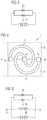
- FIG. 2shows a schematic section through the optoelectronic component in a side view
- FIGS. 3 and 5show an electrical circuit diagram of the optoelectronic component
- FIGS. 6 a and 6 bshow schematic views of planes of the carrier.
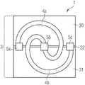
- FIG. 1shows a top view of the first segment 30 and the second segment 31 of the semiconductor body 3 on a side facing towards the carrier and advantageously a side facing away from the emission side.
- the first segment 30 and the second segment 31are separated from one another by a separation trench 32 .
- a first electrical connecting structure 5 a and a second electrical connecting structure 5 bare arranged on the semiconductor body such that they each span the separation trench 32 and are each arranged partly on the first segment 30 and partly on the second segment 31 .
- FIG. 1shows an electrical conductor path 4 a , which is arranged on the first segment 30 and on the second segment 31 , spans the separation trench 32 and connects the first connecting structure 5 a to the second connecting structure 5 b .
- the electrical conductor path 4 ahas at least one turn and acts as a coil for the inductive coupling of alternating current into the component 1 .
- the coilhere is connected in parallel with the first segment 30 and the second segment 31 .
- FIG. 2shows a cross-section through the optoelectronic component 1 along a line A from FIG. 1 .
- the first segment 30 and the second segment 31each comprise a semiconductor layer stack 6 , which comprises an n-type semiconductor layer 6 a , a p-type semiconductor layer 6 c and an active zone 6 b .
- the first electrical connecting structure 5 aconnects the n-type semiconductor layer 6 a of the first segment 30 to the p-type semiconductor layer 6 c of the second segment.
- the first electrical connecting structure 5 a in the first segment 30advantageously penetrates through the active zone 6 b located below the n-type semiconductor layer 6 a and through the p-type semiconductor layer 6 c by means of a via hole which is insulated at the edges.
- the insides of the separation trench 32advantageously comprise an electrical insulation.
- the contacting of the semiconductor layers 6 a and 6 b of the segments 30 and 31could also be carried out by the first electrical connecting structure 5 a in the reverse direction.
- the arrangement of the n-type and p-type semiconductor layersis interchangeable.
- first electrical connecting structure 5 ais contacted, e.g., on the bottom side facing away from the semiconductor body 3 to an electrical conductor path 4 a .
- a molded bodyforms a carrier 2 as a potting, in which the first electrical connecting structure 5 a and the electrical conductor path 4 a are embedded and are bridged by the molded body.
- the segments 30 and 31each comprise an emission side 3 a , which faces away from the carrier 2 .
- FIG. 2shows a transparent protective lacquer 8 , which is deposited on external surfaces of the component 1 .
- FIG. 3shows an electrical circuit diagram of a semiconductor body of the optoelectronic component with the electrical conductor path 4 a .
- the first segment 30 and the second segment 31act as diodes, which are connected in antiparallel.
- the electrical conductor path 4 aacts as a coil, which is connected in parallel with the diodes of the first segment 30 and of the second segment 31 . If an alternating current is coupled through the coil 4 a , depending on the direction of flow of the current, in other words depending on the phase of the current, one diode is connected in the forward direction and emits light and the other diode is connected in the reverse direction and emits no light. When the phases are reversed, the roles of the diodes are reversed.
- FIG. 4shows a top view of the first segment 30 and the second segment 31 of the semiconductor body 3 on a side facing towards the carrier according to FIG. 1 .
- the component 1 in FIG. 4comprises a third electrical connecting structure 5 c .
- the third electrical connecting structure 5 cis advantageously formed identically to the first connecting structure 5 a and connects the same semiconductor layers to one another as the first connecting structure 5 a .
- a further electrical conductor path 4 bis arranged between the second connecting structure 5 b and the third connecting structure 5 c on the first segment 30 and on the second segment 31 .
- the further electrical conductor path 4 b between the second connecting structure 5 b and the third connecting structure 5 cadvantageously has at least one turn and is in the shape of a coil, which is connected in parallel with the first segment 30 and the second segment 31 by way of the second connecting structure 5 b and the third connecting structure 5 c.
- FIG. 5shows an electrical circuit diagram of a semiconductor body of the optoelectronic component with the electrical conductor path 4 a according to FIG. 3 with the addition that a further electrical conductor path 4 b is connected in parallel with the segments 30 and 31 .
- the first electrical connecting structure 5 a and the third electrical connecting structure 5 care each in contact with the same semiconductor layers and therefore act as the same switching point in the circuit diagram.
- the further electrical conductor path 4 b between the second connecting structure 5 b and the third connecting structure 5 cadvantageously acts as a second coil 4 b and acts as a further voltage source during inductive current coupling.
- FIG. 6 ashows a top view of a first plane 2 a of the molded body, said plane comprising the electrical conductor path 4 a .
- the electrical conductor path 4 ais connected to the first electrical connecting structure 5 a and comprises a first turn, which covers the largest possible region of the first segment 30 and of the second segment 31 of the semiconductor body 3 on a side facing away from the emission side and spans the separation trench 32 .
- a first electrical connecting structure 5 a and a second electrical connecting structure 5 bare arranged on the semiconductor body such that they each span the separation trench 32 and are each arranged partly on the first segment 30 and partly on the second segment 31 , the first electrical connecting structure 5 a and the second electrical connecting structure 5 b being spaced apart from one another laterally along the separation trench 32 .
- the first electrical connecting structure 5 ais advantageously in direct electrical contact with the electrical conductor path 4 a . This can be achieved, e.g., with a contact via, which runs at least partly through the first plane 2 a . At a contact point D, advantageously by way of a via hole, the first turn of the electrical conductor path 4 a can be connected to a second turn or multiple turns of the electrical conductor path 4 a in a second plane located there below, as illustrated, e.g., in FIG. 6 b.
- FIG. 6 bsimilarly to FIG. 6 a , shows a second plane 2 b which is located below the first plane from FIG. 6 a and which comprises a second turn of the electrical conductor path 4 a .
- the second turnis connected in a contact point D to the first turn in the first plane located there above, advantageously being connected in series.
- the first and the second turnadvantageously run in the same direction around the segments 30 and 31 .
- the second turnoverlaps the first turn in a top view apart from the region in which the electrical conductor path 4 a is guided to the second electrical connecting structure 5 b , which extends into the second plane 2 b.
- the turns of the electrical conductor path 4 aare advantageously spaced apart from one another.
- the electrical conductor path 4 acan also have more than one turn or a turn of less than 360° in one of the two planes. Alternatively, it is also possible that the turns in the first and second planes do not overlap.
Landscapes
- Led Device Packages (AREA)
Abstract
Description
Claims (20)
Applications Claiming Priority (3)
| Application Number | Priority Date | Filing Date | Title |
|---|---|---|---|
| DE102015114010.1 | 2015-08-24 | ||
| DE102015114010.1ADE102015114010A1 (en) | 2015-08-24 | 2015-08-24 | Optoelectronic component, method for producing an optoelectronic component and method for operating an optoelectronic component |
| PCT/EP2016/069811WO2017032746A1 (en) | 2015-08-24 | 2016-08-22 | Optoelectronic component, method for manufacturing an optoelectronic component and method for operating an optoelectronic component |
Publications (2)
| Publication Number | Publication Date |
|---|---|
| US20190215928A1 US20190215928A1 (en) | 2019-07-11 |
| US11064590B2true US11064590B2 (en) | 2021-07-13 |
Family
ID=56740257
Family Applications (1)
| Application Number | Title | Priority Date | Filing Date |
|---|---|---|---|
| US15/755,013Active2037-05-08US11064590B2 (en) | 2015-08-24 | 2016-08-22 | Optoelectronic component, method for manufacturing an optoelectronic component and method for operating an optoelectronic component |
Country Status (3)
| Country | Link |
|---|---|
| US (1) | US11064590B2 (en) |
| DE (1) | DE102015114010A1 (en) |
| WO (1) | WO2017032746A1 (en) |
Families Citing this family (4)
| Publication number | Priority date | Publication date | Assignee | Title |
|---|---|---|---|---|
| DE102015114010A1 (en)* | 2015-08-24 | 2017-03-02 | Osram Opto Semiconductors Gmbh | Optoelectronic component, method for producing an optoelectronic component and method for operating an optoelectronic component |
| DE102015115706B4 (en) | 2015-09-17 | 2021-09-16 | OSRAM Opto Semiconductors Gesellschaft mit beschränkter Haftung | Process for the production of an optoelectronic component |
| EP3614437B1 (en) | 2018-08-22 | 2021-05-05 | Lumileds LLC | Semiconductor die |
| DE102018129003A1 (en)* | 2018-11-19 | 2020-05-20 | Osram Opto Semiconductors Gmbh | OPTOELECTRONIC SEMICONDUCTOR COMPONENT AND ARRANGEMENT |
Citations (49)
| Publication number | Priority date | Publication date | Assignee | Title |
|---|---|---|---|---|
| US20020139987A1 (en)* | 2001-03-29 | 2002-10-03 | Collins William David | Monolithic series/parallel led arrays formed on highly resistive substrates |
| US20050274956A1 (en)* | 2004-05-26 | 2005-12-15 | Bhat Jerome C | LED chip with integrated fast switching diode for ESD protection |
| US20060044864A1 (en)* | 2004-08-31 | 2006-03-02 | Ming-Te Lin | Structure of AC light-emitting diode dies |
| US7009199B2 (en)* | 2002-10-22 | 2006-03-07 | Cree, Inc. | Electronic devices having a header and antiparallel connected light emitting diodes for producing light from AC current |
| US20060163601A1 (en)* | 2003-02-28 | 2006-07-27 | Volker Harle | Lighting module and method the production thereof |
| US20070273299A1 (en)* | 2004-02-25 | 2007-11-29 | Michael Miskin | AC light emitting diode and AC LED drive methods and apparatus |
| US20080231180A1 (en) | 2005-07-27 | 2008-09-25 | Koninklijke Philips Electronics, N.V. | Light-Emitting Device With a Sealing Integrated Driver Circuit |
| US20090159677A1 (en)* | 2007-12-20 | 2009-06-25 | General Electric Company | Contactless power and data transfer system and method |
| US7569861B2 (en)* | 2002-08-29 | 2009-08-04 | Seoul Semiconductor Co., Ltd. | Light emitting device having light emitting elements |
| US20090212316A1 (en)* | 2005-08-30 | 2009-08-27 | Osram Opto Semiconductors Gmbh | Surface-mounted optoelectronic semiconductor component and method for the production thereof |
| DE102008024779A1 (en) | 2008-05-23 | 2009-11-26 | Osram Gesellschaft mit beschränkter Haftung | Wireless lighting module |
| US20100109030A1 (en)* | 2008-11-06 | 2010-05-06 | Koninklijke Philips Electronics N.V. | Series connected flip chip leds with growth substrate removed |
| US20100134790A1 (en)* | 2007-05-24 | 2010-06-03 | Leica Geosystems Ag | Optoelectronic longitudinal measurement method and optoelectronic longitudinal measurement device |
| US20100289007A1 (en)* | 2006-01-11 | 2010-11-18 | Ansgar Werner | Organic optoelectronic component |
| US7880182B2 (en)* | 2002-07-15 | 2011-02-01 | Epistar Corporation | Light-emitting element array |
| US20110180818A1 (en)* | 2010-08-27 | 2011-07-28 | Quarkstar, Llc | Solid State Light Sheet Using Thin LEDs For General Illumination |
| US20110193105A1 (en)* | 2010-08-27 | 2011-08-11 | Quarkstar, Llc | Solid State Light Sheet for General Illumination Having Substrates for Creating Series Connection of Dies |
| US20110210675A1 (en)* | 2010-02-28 | 2011-09-01 | Panasonic Electric Works Co., Ltd. | Light source module and lighting apparatus, and illumination apparatus using same |
| US8076680B2 (en)* | 2005-03-11 | 2011-12-13 | Seoul Semiconductor Co., Ltd. | LED package having an array of light emitting cells coupled in series |
| US20120153826A1 (en) | 2009-09-07 | 2012-06-21 | Koninklijke Philips Electronics N.V. | Wireless Electroluminescent Device |
| US8227999B2 (en)* | 2007-06-04 | 2012-07-24 | Koninklijke Philips Electronics N.V. | Light output device |
| US20120248492A1 (en)* | 2009-09-30 | 2012-10-04 | Osram Opto Semiconductors Gmbh | Optoelectronic Component |
| US8482663B2 (en)* | 2004-06-30 | 2013-07-09 | Osram Opto Semiconductors Gmbh | Light-emitting diode arrangement, optical recording device and method for the pulsed operation of at least one light-emitting diode |
| US20130201636A1 (en)* | 2010-01-29 | 2013-08-08 | Nederlandse Organisatie Voor Toegepast- Natuurwetenschappelijk Onderzoektno | Tile, assembly of tiles with a carrier, method of manufacturing an assembly |
| US20140049983A1 (en)* | 2010-11-18 | 2014-02-20 | Anthony John Nichol | Light emitting device comprising a lightguide film and aligned coupling lightguides |
| US20140146535A1 (en)* | 2011-04-05 | 2014-05-29 | Jb-Lighting Lichtanlagentechnik Gmbh | Floodlight comprising light-emitting diodes |
| US20140226317A1 (en)* | 2008-03-01 | 2014-08-14 | Goldeneye, Inc. | Barrier with integrated self cooling solid state light sources |
| US20140239809A1 (en)* | 2011-08-18 | 2014-08-28 | Lynk Labs, Inc. | Devices and systems having ac led circuits and methods of driving the same |
| US20140264407A1 (en) | 2013-03-15 | 2014-09-18 | Michael A. Tischler | Stress relief for array-based electronic devices |
| US20140301074A1 (en)* | 2013-03-06 | 2014-10-09 | Lynk Labs, Inc. | Led lighting system, method, and apparatus |
| US20140334137A1 (en)* | 2012-02-02 | 2014-11-13 | The Procter & Gamble Company | Bidirectional light sheet |
| US20140368125A1 (en)* | 2013-06-09 | 2014-12-18 | Q Technology, Inc. | Lighting panel with distributed capacitance |
| US20150054348A1 (en)* | 2011-02-19 | 2015-02-26 | Lequio Power Technology Corp. | Power supply device, power reception device, and power supply/reception device |
| US20150270719A1 (en)* | 2008-09-27 | 2015-09-24 | Witricity Corporation | Wireless Power System Including Impedance matching network |
| US20150380390A1 (en)* | 2013-02-28 | 2015-12-31 | Koninklijke Philips N.V. | Simple led package suitable for capacitive driving |
| US20160043571A1 (en)* | 2008-09-27 | 2016-02-11 | Witricity Corporation | Resonator enclosure |
| US20160081602A1 (en)* | 2014-09-18 | 2016-03-24 | Covidien Lp | Methods and systems for providing power to light sources of a physiological monitor |
| US20160093783A1 (en)* | 2013-04-09 | 2016-03-31 | Osram Opto Semiconductors Gmbh | Optoelectronic component and method of production thereof |
| US20160157306A1 (en)* | 2014-12-01 | 2016-06-02 | Dialog Semiconductor (Uk) Limited | Resonance Converter for Driving Multiple AC LED Strings |
| US9391118B2 (en)* | 2007-01-22 | 2016-07-12 | Cree, Inc. | Fault tolerant light emitters, systems incorporating fault tolerant light emitters and methods of fabricating fault tolerant light emitters |
| US20160369981A1 (en)* | 2013-11-18 | 2016-12-22 | Emdedesign Gmbh | Lamp Comprising at Least One OLED Lighting Means |
| DE102015111558A1 (en) | 2015-07-16 | 2017-01-19 | Osram Opto Semiconductors Gmbh | Optoelectronic component and a method for producing an optoelectronic component |
| US9590008B2 (en)* | 2008-11-28 | 2017-03-07 | Osram Opto Semiconductors Gmbh | Radiation-emitting semiconductor chip |
| US9615420B2 (en)* | 2004-02-25 | 2017-04-04 | Lynk Labs, Inc. | LED lighting system |
| US20170108176A1 (en)* | 2008-10-16 | 2017-04-20 | Kumho Electric Inc. | Led fluorescent lamp |
| US20170184281A1 (en)* | 2014-05-20 | 2017-06-29 | Philips Lighting Holding B.V. | Conformal coated lighting or lumination system |
| US20170279019A1 (en)* | 2014-12-26 | 2017-09-28 | Panasonic Intellectual Property Management Co., Ltd. | Light emitting device and method for manufacturing same |
| US20190014631A1 (en)* | 2015-12-23 | 2019-01-10 | Koninklijke Philips N.V. | Load arrangement and electrical power arrangement for powering a load |
| US20190215928A1 (en)* | 2015-08-24 | 2019-07-11 | Osram Opto Semiconductors Gmbh | Optoelectronic Component, Method for Manufacturing an Optoelectronic Component and Method for Operating an Optoelectronic Component |
- 2015
- 2015-08-24DEDE102015114010.1Apatent/DE102015114010A1/enactivePending
- 2016
- 2016-08-22USUS15/755,013patent/US11064590B2/enactiveActive
- 2016-08-22WOPCT/EP2016/069811patent/WO2017032746A1/ennot_activeCeased
Patent Citations (51)
| Publication number | Priority date | Publication date | Assignee | Title |
|---|---|---|---|---|
| US20020139987A1 (en)* | 2001-03-29 | 2002-10-03 | Collins William David | Monolithic series/parallel led arrays formed on highly resistive substrates |
| US7880182B2 (en)* | 2002-07-15 | 2011-02-01 | Epistar Corporation | Light-emitting element array |
| US7569861B2 (en)* | 2002-08-29 | 2009-08-04 | Seoul Semiconductor Co., Ltd. | Light emitting device having light emitting elements |
| US7009199B2 (en)* | 2002-10-22 | 2006-03-07 | Cree, Inc. | Electronic devices having a header and antiparallel connected light emitting diodes for producing light from AC current |
| US20060163601A1 (en)* | 2003-02-28 | 2006-07-27 | Volker Harle | Lighting module and method the production thereof |
| US20070273299A1 (en)* | 2004-02-25 | 2007-11-29 | Michael Miskin | AC light emitting diode and AC LED drive methods and apparatus |
| US9615420B2 (en)* | 2004-02-25 | 2017-04-04 | Lynk Labs, Inc. | LED lighting system |
| US20050274956A1 (en)* | 2004-05-26 | 2005-12-15 | Bhat Jerome C | LED chip with integrated fast switching diode for ESD protection |
| US8482663B2 (en)* | 2004-06-30 | 2013-07-09 | Osram Opto Semiconductors Gmbh | Light-emitting diode arrangement, optical recording device and method for the pulsed operation of at least one light-emitting diode |
| US7531843B2 (en)* | 2004-08-31 | 2009-05-12 | Industrial Technology Research Institute | Structure of AC light-emitting diode dies |
| US20060044864A1 (en)* | 2004-08-31 | 2006-03-02 | Ming-Te Lin | Structure of AC light-emitting diode dies |
| US8076680B2 (en)* | 2005-03-11 | 2011-12-13 | Seoul Semiconductor Co., Ltd. | LED package having an array of light emitting cells coupled in series |
| US20080231180A1 (en) | 2005-07-27 | 2008-09-25 | Koninklijke Philips Electronics, N.V. | Light-Emitting Device With a Sealing Integrated Driver Circuit |
| US20090212316A1 (en)* | 2005-08-30 | 2009-08-27 | Osram Opto Semiconductors Gmbh | Surface-mounted optoelectronic semiconductor component and method for the production thereof |
| US20100289007A1 (en)* | 2006-01-11 | 2010-11-18 | Ansgar Werner | Organic optoelectronic component |
| US9391118B2 (en)* | 2007-01-22 | 2016-07-12 | Cree, Inc. | Fault tolerant light emitters, systems incorporating fault tolerant light emitters and methods of fabricating fault tolerant light emitters |
| US20100134790A1 (en)* | 2007-05-24 | 2010-06-03 | Leica Geosystems Ag | Optoelectronic longitudinal measurement method and optoelectronic longitudinal measurement device |
| US8227999B2 (en)* | 2007-06-04 | 2012-07-24 | Koninklijke Philips Electronics N.V. | Light output device |
| US20090159677A1 (en)* | 2007-12-20 | 2009-06-25 | General Electric Company | Contactless power and data transfer system and method |
| US20140226317A1 (en)* | 2008-03-01 | 2014-08-14 | Goldeneye, Inc. | Barrier with integrated self cooling solid state light sources |
| DE102008024779A1 (en) | 2008-05-23 | 2009-11-26 | Osram Gesellschaft mit beschränkter Haftung | Wireless lighting module |
| US8901857B2 (en) | 2008-05-23 | 2014-12-02 | Osram Gesellschaft Mit Beschraenkter Haftung | Wireless supplyable lighting module |
| US20160043571A1 (en)* | 2008-09-27 | 2016-02-11 | Witricity Corporation | Resonator enclosure |
| US20150270719A1 (en)* | 2008-09-27 | 2015-09-24 | Witricity Corporation | Wireless Power System Including Impedance matching network |
| US20170108176A1 (en)* | 2008-10-16 | 2017-04-20 | Kumho Electric Inc. | Led fluorescent lamp |
| US20100109030A1 (en)* | 2008-11-06 | 2010-05-06 | Koninklijke Philips Electronics N.V. | Series connected flip chip leds with growth substrate removed |
| US9590008B2 (en)* | 2008-11-28 | 2017-03-07 | Osram Opto Semiconductors Gmbh | Radiation-emitting semiconductor chip |
| US20120153826A1 (en) | 2009-09-07 | 2012-06-21 | Koninklijke Philips Electronics N.V. | Wireless Electroluminescent Device |
| US20120248492A1 (en)* | 2009-09-30 | 2012-10-04 | Osram Opto Semiconductors Gmbh | Optoelectronic Component |
| US20130201636A1 (en)* | 2010-01-29 | 2013-08-08 | Nederlandse Organisatie Voor Toegepast- Natuurwetenschappelijk Onderzoektno | Tile, assembly of tiles with a carrier, method of manufacturing an assembly |
| US20110210675A1 (en)* | 2010-02-28 | 2011-09-01 | Panasonic Electric Works Co., Ltd. | Light source module and lighting apparatus, and illumination apparatus using same |
| US20110193105A1 (en)* | 2010-08-27 | 2011-08-11 | Quarkstar, Llc | Solid State Light Sheet for General Illumination Having Substrates for Creating Series Connection of Dies |
| US20110180818A1 (en)* | 2010-08-27 | 2011-07-28 | Quarkstar, Llc | Solid State Light Sheet Using Thin LEDs For General Illumination |
| US20140049983A1 (en)* | 2010-11-18 | 2014-02-20 | Anthony John Nichol | Light emitting device comprising a lightguide film and aligned coupling lightguides |
| US20150054348A1 (en)* | 2011-02-19 | 2015-02-26 | Lequio Power Technology Corp. | Power supply device, power reception device, and power supply/reception device |
| US20140146535A1 (en)* | 2011-04-05 | 2014-05-29 | Jb-Lighting Lichtanlagentechnik Gmbh | Floodlight comprising light-emitting diodes |
| US20140239809A1 (en)* | 2011-08-18 | 2014-08-28 | Lynk Labs, Inc. | Devices and systems having ac led circuits and methods of driving the same |
| US20140334137A1 (en)* | 2012-02-02 | 2014-11-13 | The Procter & Gamble Company | Bidirectional light sheet |
| US20150380390A1 (en)* | 2013-02-28 | 2015-12-31 | Koninklijke Philips N.V. | Simple led package suitable for capacitive driving |
| US20140301074A1 (en)* | 2013-03-06 | 2014-10-09 | Lynk Labs, Inc. | Led lighting system, method, and apparatus |
| US20140264407A1 (en) | 2013-03-15 | 2014-09-18 | Michael A. Tischler | Stress relief for array-based electronic devices |
| US20160093783A1 (en)* | 2013-04-09 | 2016-03-31 | Osram Opto Semiconductors Gmbh | Optoelectronic component and method of production thereof |
| US20140368125A1 (en)* | 2013-06-09 | 2014-12-18 | Q Technology, Inc. | Lighting panel with distributed capacitance |
| US20160369981A1 (en)* | 2013-11-18 | 2016-12-22 | Emdedesign Gmbh | Lamp Comprising at Least One OLED Lighting Means |
| US20170184281A1 (en)* | 2014-05-20 | 2017-06-29 | Philips Lighting Holding B.V. | Conformal coated lighting or lumination system |
| US20160081602A1 (en)* | 2014-09-18 | 2016-03-24 | Covidien Lp | Methods and systems for providing power to light sources of a physiological monitor |
| US20160157306A1 (en)* | 2014-12-01 | 2016-06-02 | Dialog Semiconductor (Uk) Limited | Resonance Converter for Driving Multiple AC LED Strings |
| US20170279019A1 (en)* | 2014-12-26 | 2017-09-28 | Panasonic Intellectual Property Management Co., Ltd. | Light emitting device and method for manufacturing same |
| DE102015111558A1 (en) | 2015-07-16 | 2017-01-19 | Osram Opto Semiconductors Gmbh | Optoelectronic component and a method for producing an optoelectronic component |
| US20190215928A1 (en)* | 2015-08-24 | 2019-07-11 | Osram Opto Semiconductors Gmbh | Optoelectronic Component, Method for Manufacturing an Optoelectronic Component and Method for Operating an Optoelectronic Component |
| US20190014631A1 (en)* | 2015-12-23 | 2019-01-10 | Koninklijke Philips N.V. | Load arrangement and electrical power arrangement for powering a load |
Also Published As
| Publication number | Publication date |
|---|---|
| DE102015114010A1 (en) | 2017-03-02 |
| WO2017032746A1 (en) | 2017-03-02 |
| US20190215928A1 (en) | 2019-07-11 |
Similar Documents
| Publication | Publication Date | Title |
|---|---|---|
| US11064590B2 (en) | Optoelectronic component, method for manufacturing an optoelectronic component and method for operating an optoelectronic component | |
| US9142534B2 (en) | Light-emitting device | |
| EP2722899B1 (en) | Light emitting device | |
| US8450765B2 (en) | Light emitting diode chip and method for manufacturing the same | |
| US9620692B2 (en) | Lead frame and light emitting diode package having the same | |
| CN105409017B (en) | Surface-mountable optoelectronic semiconductor component and the method for manufacturing at least one surface-mountable optoelectronic semiconductor component | |
| CN105103288A (en) | Optoelectronic semiconductor chips and optoelectronic modules | |
| US20110156613A1 (en) | Lighting apparatus | |
| US10157960B2 (en) | Light-emitting device with electrode extending layer | |
| JP2015532539A (en) | Optoelectronic component with built-in protection diode and method of manufacturing the same | |
| CN102916108B (en) | Package structure for LED | |
| US20130112998A1 (en) | Solid state light emitting semiconductor device | |
| CN207719230U (en) | High voltage led chip | |
| CN103187425A (en) | Semiconductor light emitting device and led module | |
| US20160126225A1 (en) | Light-emitting device | |
| US8270444B2 (en) | Side emitting semiconductor package | |
| US8957452B2 (en) | Light emitting diode structure | |
| US10062729B2 (en) | Light-emitting diode chip | |
| CN102867819B (en) | Package structure for LED and manufacture method thereof | |
| US10879136B2 (en) | Method for producing an optoelectronic device | |
| US20160141476A1 (en) | Package structure and method of manufacture thereof, and carrier | |
| US20120080700A1 (en) | Light emitting diode package and method for manufacturing the same | |
| KR101034130B1 (en) | Light emitting device package and its manufacturing method | |
| US20090236615A1 (en) | Light emitting diode | |
| KR20170119193A (en) | Light emitting diode having plurality of light emitting cells |
Legal Events
| Date | Code | Title | Description |
|---|---|---|---|
| FEPP | Fee payment procedure | Free format text:ENTITY STATUS SET TO UNDISCOUNTED (ORIGINAL EVENT CODE: BIG.); ENTITY STATUS OF PATENT OWNER: LARGE ENTITY | |
| AS | Assignment | Owner name:OSRAM OPTO SEMICONDUCTORS GMBH, GERMANY Free format text:ASSIGNMENT OF ASSIGNORS INTEREST;ASSIGNOR:PERZLMAIER, KORBINIAN;REEL/FRAME:045509/0586 Effective date:20180322 | |
| STPP | Information on status: patent application and granting procedure in general | Free format text:NON FINAL ACTION MAILED | |
| STPP | Information on status: patent application and granting procedure in general | Free format text:RESPONSE TO NON-FINAL OFFICE ACTION ENTERED AND FORWARDED TO EXAMINER | |
| AS | Assignment | Owner name:OSRAM OLED GMBH, GERMANY Free format text:ASSIGNMENT OF ASSIGNORS INTEREST;ASSIGNOR:OSRAM OPTO SEMICONDUCTORS GMBH;REEL/FRAME:051464/0504 Effective date:20191218 | |
| STPP | Information on status: patent application and granting procedure in general | Free format text:RESPONSE TO NON-FINAL OFFICE ACTION ENTERED AND FORWARDED TO EXAMINER | |
| STPP | Information on status: patent application and granting procedure in general | Free format text:NOTICE OF ALLOWANCE MAILED -- APPLICATION RECEIVED IN OFFICE OF PUBLICATIONS | |
| STPP | Information on status: patent application and granting procedure in general | Free format text:PUBLICATIONS -- ISSUE FEE PAYMENT RECEIVED | |
| STPP | Information on status: patent application and granting procedure in general | Free format text:PUBLICATIONS -- ISSUE FEE PAYMENT VERIFIED | |
| STCF | Information on status: patent grant | Free format text:PATENTED CASE | |
| MAFP | Maintenance fee payment | Free format text:PAYMENT OF MAINTENANCE FEE, 4TH YEAR, LARGE ENTITY (ORIGINAL EVENT CODE: M1551); ENTITY STATUS OF PATENT OWNER: LARGE ENTITY Year of fee payment:4 |