US11063378B2 - Printed circuit board cable clip for signal sensitive applications - Google Patents
Printed circuit board cable clip for signal sensitive applicationsDownload PDFInfo
- Publication number
- US11063378B2 US11063378B2US16/812,265US202016812265AUS11063378B2US 11063378 B2US11063378 B2US 11063378B2US 202016812265 AUS202016812265 AUS 202016812265AUS 11063378 B2US11063378 B2US 11063378B2
- Authority
- US
- United States
- Prior art keywords
- cable
- clip
- conductive
- section
- pcba
- Prior art date
- Legal status (The legal status is an assumption and is not a legal conclusion. Google has not performed a legal analysis and makes no representation as to the accuracy of the status listed.)
- Active
Links
Images


Classifications
- H—ELECTRICITY
- H01—ELECTRIC ELEMENTS
- H01R—ELECTRICALLY-CONDUCTIVE CONNECTIONS; STRUCTURAL ASSOCIATIONS OF A PLURALITY OF MUTUALLY-INSULATED ELECTRICAL CONNECTING ELEMENTS; COUPLING DEVICES; CURRENT COLLECTORS
- H01R12/00—Structural associations of a plurality of mutually-insulated electrical connecting elements, specially adapted for printed circuits, e.g. printed circuit boards [PCB], flat or ribbon cables, or like generally planar structures, e.g. terminal strips, terminal blocks; Coupling devices specially adapted for printed circuits, flat or ribbon cables, or like generally planar structures; Terminals specially adapted for contact with, or insertion into, printed circuits, flat or ribbon cables, or like generally planar structures
- H01R12/50—Fixed connections
- H01R12/51—Fixed connections for rigid printed circuits or like structures
- H01R12/53—Fixed connections for rigid printed circuits or like structures connecting to cables except for flat or ribbon cables
- A—HUMAN NECESSITIES
- A61—MEDICAL OR VETERINARY SCIENCE; HYGIENE
- A61N—ELECTROTHERAPY; MAGNETOTHERAPY; RADIATION THERAPY; ULTRASOUND THERAPY
- A61N1/00—Electrotherapy; Circuits therefor
- A61N1/18—Applying electric currents by contact electrodes
- A61N1/32—Applying electric currents by contact electrodes alternating or intermittent currents
- A61N1/38—Applying electric currents by contact electrodes alternating or intermittent currents for producing shock effects
- A61N1/39—Heart defibrillators
- A61N1/3904—External heart defibrillators [EHD]
- H—ELECTRICITY
- H01—ELECTRIC ELEMENTS
- H01R—ELECTRICALLY-CONDUCTIVE CONNECTIONS; STRUCTURAL ASSOCIATIONS OF A PLURALITY OF MUTUALLY-INSULATED ELECTRICAL CONNECTING ELEMENTS; COUPLING DEVICES; CURRENT COLLECTORS
- H01R4/00—Electrically-conductive connections between two or more conductive members in direct contact, i.e. touching one another; Means for effecting or maintaining such contact; Electrically-conductive connections having two or more spaced connecting locations for conductors and using contact members penetrating insulation
- H01R4/02—Soldered or welded connections
- H01R4/027—Soldered or welded connections comprising means for positioning or holding the parts to be soldered or welded
- H—ELECTRICITY
- H05—ELECTRIC TECHNIQUES NOT OTHERWISE PROVIDED FOR
- H05K—PRINTED CIRCUITS; CASINGS OR CONSTRUCTIONAL DETAILS OF ELECTRIC APPARATUS; MANUFACTURE OF ASSEMBLAGES OF ELECTRICAL COMPONENTS
- H05K1/00—Printed circuits
- H05K1/02—Details
- H05K1/11—Printed elements for providing electric connections to or between printed circuits
- H05K1/111—Pads for surface mounting, e.g. lay-out
- H—ELECTRICITY
- H05—ELECTRIC TECHNIQUES NOT OTHERWISE PROVIDED FOR
- H05K—PRINTED CIRCUITS; CASINGS OR CONSTRUCTIONAL DETAILS OF ELECTRIC APPARATUS; MANUFACTURE OF ASSEMBLAGES OF ELECTRICAL COMPONENTS
- H05K1/00—Printed circuits
- H05K1/18—Printed circuits structurally associated with non-printed electric components
- H05K1/181—Printed circuits structurally associated with non-printed electric components associated with surface mounted components
- H—ELECTRICITY
- H05—ELECTRIC TECHNIQUES NOT OTHERWISE PROVIDED FOR
- H05K—PRINTED CIRCUITS; CASINGS OR CONSTRUCTIONAL DETAILS OF ELECTRIC APPARATUS; MANUFACTURE OF ASSEMBLAGES OF ELECTRICAL COMPONENTS
- H05K2201/00—Indexing scheme relating to printed circuits covered by H05K1/00
- H05K2201/10—Details of components or other objects attached to or integrated in a printed circuit board
- H05K2201/10227—Other objects, e.g. metallic pieces
- H05K2201/1031—Surface mounted metallic connector elements
- H—ELECTRICITY
- H05—ELECTRIC TECHNIQUES NOT OTHERWISE PROVIDED FOR
- H05K—PRINTED CIRCUITS; CASINGS OR CONSTRUCTIONAL DETAILS OF ELECTRIC APPARATUS; MANUFACTURE OF ASSEMBLAGES OF ELECTRICAL COMPONENTS
- H05K2201/00—Indexing scheme relating to printed circuits covered by H05K1/00
- H05K2201/10—Details of components or other objects attached to or integrated in a printed circuit board
- H05K2201/10227—Other objects, e.g. metallic pieces
- H05K2201/10356—Cables
- H—ELECTRICITY
- H05—ELECTRIC TECHNIQUES NOT OTHERWISE PROVIDED FOR
- H05K—PRINTED CIRCUITS; CASINGS OR CONSTRUCTIONAL DETAILS OF ELECTRIC APPARATUS; MANUFACTURE OF ASSEMBLAGES OF ELECTRICAL COMPONENTS
- H05K2201/00—Indexing scheme relating to printed circuits covered by H05K1/00
- H05K2201/10—Details of components or other objects attached to or integrated in a printed circuit board
- H05K2201/10613—Details of electrical connections of non-printed components, e.g. special leads
- H05K2201/10742—Details of leads
- H05K2201/10886—Other details
- H05K2201/10916—Terminals having auxiliary metallic piece, e.g. for soldering
- H—ELECTRICITY
- H05—ELECTRIC TECHNIQUES NOT OTHERWISE PROVIDED FOR
- H05K—PRINTED CIRCUITS; CASINGS OR CONSTRUCTIONAL DETAILS OF ELECTRIC APPARATUS; MANUFACTURE OF ASSEMBLAGES OF ELECTRICAL COMPONENTS
- H05K2201/00—Indexing scheme relating to printed circuits covered by H05K1/00
- H05K2201/10—Details of components or other objects attached to or integrated in a printed circuit board
- H05K2201/10613—Details of electrical connections of non-printed components, e.g. special leads
- H05K2201/10742—Details of leads
- H05K2201/10886—Other details
- H05K2201/10924—Leads formed from a punched metal foil
- Y—GENERAL TAGGING OF NEW TECHNOLOGICAL DEVELOPMENTS; GENERAL TAGGING OF CROSS-SECTIONAL TECHNOLOGIES SPANNING OVER SEVERAL SECTIONS OF THE IPC; TECHNICAL SUBJECTS COVERED BY FORMER USPC CROSS-REFERENCE ART COLLECTIONS [XRACs] AND DIGESTS
- Y02—TECHNOLOGIES OR APPLICATIONS FOR MITIGATION OR ADAPTATION AGAINST CLIMATE CHANGE
- Y02P—CLIMATE CHANGE MITIGATION TECHNOLOGIES IN THE PRODUCTION OR PROCESSING OF GOODS
- Y02P70/00—Climate change mitigation technologies in the production process for final industrial or consumer products
- Y02P70/50—Manufacturing or production processes characterised by the final manufactured product
Definitions
- Wiresare utilized in various technologies. Wires are capable of carrying signals (e.g., electrical signal and/or data signal). Some wires may be used in technologies involving sensitive signals such as, but not limited to, healthcare device technologies.
- One example of a healthcare device technologymay be defibrillator technology. Maintaining integrity of the signals carried by the wires utilized in defibrillator technology may be relevant. Accordingly, wires utilized in defibrillator technology may be employed managing various concerns with the signal.
- wires utilized in defibrillator technologymay include wires utilized in wearable cardioverter defibrillator (WCD) systems.
- Wires utilized in WCD systemsmay include various structures to facilitate maintenance of signal integrity.
- the wires utilized in WCD systemsmay include various wires such as, but not limited to, an electrocardiogram (ECG) cable.
- ECG cablemay include various structures to help facilitate maintenance of signal integrity such as, but not limited to, a coaxial cable.
- a structuremay include various construction such as, but not limited to, a triaxial construction.
- the triaxial constructionmay include a center conductor (e.g., metal wire), a first insulation layer, an inner shield layer, a second insulation layer, an outer shield, and a jacket.
- the various layers of the triaxial constructionhelp facilitate maintenance of signal integrity (e.g., high quality ECG signal measurement in a WCD system).
- the cablemay commonly provide signals to various signal processing electronic components.
- the electronic componentsmay be deployed on a printed circuit board (PCB). Accordingly, the cable may be communicatively coupled to the PCB to provide the signals to the electronic components for various processing forming a PCB assembly (PCBA).
- PCBAPCB assembly
- the cablemay be soldered to the PCB by hand or utilize a relatively long clip connection for an electrical connection. Both of these methodologies may be prone to damage the cable due to heat effects of the solder melting through some of the layers of the cable (e.g., inner insulator layer). Additionally, insulator layers may be relatively sensitive to heat effects due to the dielectric material being selected to minimizing triboelectric noise, which may be generated during cable movement. For example, low triboelectric noise materials may have relatively low thermal softening temperatures, which may make them susceptible to melting and displacement when heat is applied to the shield layers for soldering. Melting and displacement may result in some manufacturing defects due to the shield layers either shorting together or shorting with the center conductor when excessive heat was applied causing the insulation layers to melt and be displaced.
- Example apparatusmay include a cable connecting clip.
- the cable connecting clipmay include a channel that may be configured to receive a cable having a structure.
- the channelmay be shaped to fit the cable.
- the cable connecting clipmay have a saddle section having a first flange and a second flange on the opposite sides of the channel. The flanges may be configured to guide the cable into the channel.
- a connecting pad sectionmay be disposed on the cable connecting clip and may be configured to couple a conductive layer of the cable to the clip.
- the present disclosurealso describes a printed circuit board assembly (PCBA) system that may include a cable having a signal conductor and at least a first conductive layer.
- the PCBAmay include a substrate having at least a first and second conductive regions.
- the PCBAmay also include a first conductive clip having a pad section, a saddle section, and a neck section connected between the pad and saddle sections, the neck section being narrower than the pad and saddle sections.
- the portion of the cablemay be disposed in the saddle section of the first conductive clip, and a portion of the first conductive layer of the cable is soldered to the saddle section of the first conductive clip.
- the pad section of the first conductive clipis soldered to the first conductive region of the substrate to electrically connect the portion of the first conductive layer of the cable to the first conductive region of the substrate, and the signal conductor of the shielding cable is soldered to the second conductive region of the substrate.
- subject matter of the present disclosuremay be applicable to wearable cardioverter defibrillator (WCD) system having a PCBA with clips.
- WCDwearable cardioverter defibrillator
- FIG. 1illustrates a cable connecting clip in accordance with various embodiments
- FIG. 2illustrates a clip as may be utilized in accordance with various embodiments of the disclosure
- FIG. 3illustrates a printed circuit board assembly (PCBA) utilizing more than one clip, in accordance with various embodiments
- FIG. 4illustrates one or more clips on a PCBA, in accordance with various embodiments
- FIG. 5illustrates a clip, in accordance with another embodiment
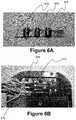
- FIGS. 6A and 6Billustrate a clip, in accordance with another embodiment
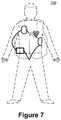
- FIG. 7illustrates an example application of a clip, in accordance with various embodiments.
- FIG. 8is a block diagram illustrating components of defibrillator device, which may be used with various embodiments.
- PCBAprinted circuit board assembly
- a cablemay carry various electrical signals.
- the electrical signalsmay be processed by various electronic components.
- the cablesmay be communicatively coupled to the electronic components by various connections.
- the connectionsmay be facilitated by a connection of the cable to an electronic component platform such as, but not limited to, a printed circuit board (PCB).
- the PCBmay have various communicative connections (e.g., electrical lines and/or vias).
- the communicative connectionsmay be connected to the electrical components for processing. Accordingly, the manner with which the cable connects to the PCB may be relevant to signal integrity received by the electronic components via the cable.
- a signal communicating cablemay be utilized in healthcare technology such as, but not limited to, defibrillator technology, where signal integrity may be relevant (e.g., noise-sensitivity).
- An example of a cable utilized in defibrillator technologymay be a cable utilized in wearable cardioverter defibrillator (WCD) systems.
- WCDwearable cardioverter defibrillator
- ECGelectrocardiogram
- a cable structuremay include a biaxial structure, which may have a center conductor (e.g., a metal wire), which may typically carry the noise-sensitive signal (e.g., ECG signal), an insulator layer, which may be made from dielectric material surrounding the center conductor, a conductive shield (commonly, braid-like), which may surround the insulator layer, and a final insulator layer, which may surround the conductive shield.
- a center conductore.g., a metal wire
- the noise-sensitive signale.g., ECG signal
- an insulator layerwhich may be made from dielectric material surrounding the center conductor
- a conductive shieldcommonly, braid-like
- a final insulator layerwhich may surround the conductive shield.
- a cable structuremay include a triaxial cable structure having a center conductor (e.g., a metal wire), which may typically carry the noise-sensitive signal (e.g., ECG signal), an inner insulator layer, which may be made from dielectric material surrounding the center conductor, an inner conductive shield (commonly, braid-like), which may surround the inner insulator layer, an outer conductive shield (commonly, braid-like), which may surround the outer insulator layer, and a final insulator layer, which may surround the outer conductive shield.
- the utilization of the structure of the cablemay be based, at least in part, on the application of the cable and the sensitivity of the application to signal noise and/or integrity.
- the structure of the cablemay be determined to be triaxial as described above.
- At least one end of the cablemay be communicatively coupled to a PCB to facilitate processing of the ECG signal to and/or from the cable.
- the various layers of the cablemay be stripped back to expose the various layers (e.g., center conductor, insulator layers, and conductive shield layers). The stripped back cable may then be soldered onto the PCB forming a PCB assembly.
- a wire connecting clipmay be disposed on the PCB.
- the clipmay be soldered onto the PCB and be a predetermined distance from a conductive signal pad such as, but not limited to, a substantially flat landing pad.
- the clipmay be communicatively coupled to various electronic components on the PCB (also referred herein as a PCB assembly or PCBA).
- the clipmay be communicatively coupled to the PBC by being soldered onto one or more signal lines in various conductive regions of the PCB.
- the stripped back cable(e.g., exposing predetermined lengths of the various layers of the structure of the cable) may be disposed into the clip.
- the clipmay have flanges to guide the cable into a channel of the clip substantially seating the cable into the clip. While the cable is soldered to the clip, the clip may facilitate holding of the cable in its position within the channel. The position of the clip may be on the PCB to facilitate accurate placement of the cable.
- the center conductorwhich may facilitate communication of a signal (i.e., signal conductor), may be communicatively coupled (e.g., soldered) to a conductive signal pad such as, but not limited to, a flat landing pad.
- the clipmay be positioned a predetermined distance from the landing pad.
- the cablemay be stripped to expose the various layers of the structure corresponding to the predetermined distance. Accordingly, the stripped cable may be placed into the clip, the cable may be soldered to the clip, the center conductor may be positioned on the landing pad, and the center conductor may be soldered to the landing pad.
- the clipmay facilitate accurate positioning of the cable (i.e., the various exposed layers), the process of stripping the cable, placement of the cable onto the PCB, and soldering the cable onto the PCB may at least partially or in any combination be substantially automated. Additionally, the clip may help facilitate envelopment of the shield layers with solder without the application of significant amount of force resulting in facilitation of prevention of melting and displacement of the insulation layers of the cable. Further, the clip may have various features, including selection of materials, to help facilitate compensation of the mechanical effects of the soldering process (e.g., dimensional changes due to heat, heat dissipation, heat isolation controlling the spread of heat to various parts of the cable and its structures, etc.).
- FIG. 1illustrates a cable connecting clip in accordance with various embodiments.
- a cable connecting clip 100may include a channel 102 , a first flange 104 , a second flange 106 , and a connecting pad 108 .
- the channel 102may be configured to receive a cable 202 (shown in FIG. 2 ) with the channel 102 having a shape to substantially fit the cable 202 .
- the first flange 104 and the second flange 106may be disposed on opposite sides of the channel and be configured to guide the cable 202 into the channel 102 .
- the connecting pad 108may be disposed on an end 110 of the channel 102 .
- the connecting pad 108may be configured to couple a conductive layer 212 (shown in FIG. 2 ) of the cable 202 to the clip 100 .
- the channel 102may include a thermal mechanical compensating structure 112 .
- the thermal mechanical compensating structure 112may be in the form of a slot having a predetermined dimension to manage mechanical stresses that may be imparted on the clip 100 due to heat from soldering (e.g., twisting, expansion, swelling, etc.).
- a heat transfer management structure 114may be present between the connecting pad 108 and the channel 102 .
- the heat transfer management structure 114may in the form of a neck (i.e., a narrow thermal path) between the channel 102 and the connecting pad 108 .
- thermal mechanical compensating structure 112 and the heat transfer management structure 114may be in the form of a slot and a neck respectively, the thermal mechanical compensating structure 112 and the heat transfer management structure 114 may be in a variety of forms and structures.
- the thermal mechanical compensating structure 112may be in the form of a hole, an ellipse, a solid of the same material, a solid of a different material, a rectangular hole, etc. and any combination thereof.
- the heat transfer management structure 114may be in a variety of forms such as, but not limited to, a wire, solid material, hybrid material, a gap, etc. and any combination thereof.
- the first flange 104 and the second flange 106may substantially form a “V” type shape to guide the cable 202 , in particular the conductive layer 212 of the cable 202 , into the channel 102 .
- the first flange 104 and the second flange 106may form a variety of shapes to help guide the cable 202 into the channel.
- the first flange 104 and the second flange 106may be configured to help facilitate holding the cable 202 in place.
- the first flange 104 and the second flange 106may help guide the cable 202 into the channel 102 and help to hold the cable 202 within the channel 102 by a pinching action on the cable 202 .
- the channel 102 , the first flange 104 , and the second flange 106may collectively act as a clip holding the cable 202 in place during and after soldering.
- the clip 100may be made from a variety of material such as, but not limited to, metals.
- metalsmay include tin, cadmium, gold, silver, palladium, rhodium, copper, bronze, brass, lead, nickel silver, beryllium copper, carbon steel, low alloy steel, zinc, nickel, aluminum, aluminum bronze, high alloy steels, stainless steel, cast iron, chromium, titanium, tantalum, magnesium, etc., and any combination thereof.
- the clipmay be made of a variety of polymer material such as, but not limited to, carbon materials.
- carbon materialsmay include carbon fibers, carbon nanotube fibers, carbon-carbon combinations, carbon-metal combinations, etc., and any combination thereof.
- the clip 100may also be referred to as a conductive clip, and accordingly, the terms clip and conductive clip may be used interchangeably.
- the combination of the features the first flange 104 , the second flange 106 , and the channel 102may be referred together as a saddle, and accordingly, the term saddle may refer to the combination of features as described.
- FIG. 2illustrates a clip 100 (shown in FIG. 1 ) as may be utilized in accordance with various embodiments of the disclosure.
- a printed circuit board assembly (PCBA) system 200may include the clip 100 , which may be disposed on a printed circuit board (PCB) 216 .
- the PCB 216may have a first conductive region 218 and a second conductive region 220 , where the clip 100 may be disposed on the first conductive region 218 of the PCB 216 (i.e., on a substrate of the PBC 216 ).
- the clip 100may be configured to receive the cable 202 .
- the cable 202may have a predetermined structure as previously described.
- the cable 202may be of a coaxial type such as, but not limited to, a triaxial type cable. Accordingly, in the example illustrated in FIG. 2 , the cable 202 may have a center conductor 204 , an inner insulator layer 206 , an inner conductive shield 208 , an outer insulator layer 210 , an outer conductive shield 212 , and a final insulator layer 214 . As shown in FIG. 2 , the cable 202 may be stripped back exposing the various layers 204 , 206 , 208 , 210 , and 212 .
- the lengths of the strippingmay be based, at least in part, on the proximate locations of the conductive regions 218 and 220 .
- a portion of the cable 202e.g., the outer conductive shield 212
- the outer conductive shield 212 portionmay be soldered to the saddle section of the clip 100 .
- the pad section 108(shown in FIG. 1 ) may be soldered to the first conductive region 218 of the PCB 216 , thereby causing an electrical connection between the first conductive region 218 of the PCB 216 and the outer conductive shield 212 of the cable 202 .
- the center conductor 204i.e., signal conductor
- of the cable 202may be soldered to the second conductive region 220 of the PCB 216 .
- the clip 100may help to facilitate accurate placement of the cable 202 in its appropriate position on the PCB 216 (e.g., accurately hold the layers 204 , 206 , 208 , 210 , and 212 of the cable 202 in their correct positions for proper connection with the PCBA 200 ). Additionally, the clip 100 may help facilitate envelopment of the shield layers 204 , 206 , 208 , 210 , and 212 of the cable 202 with solder without the application of significant amount of force resulting in facilitation of prevention of melting and displacement of the insulation layers 204 , 206 , 208 , 210 , and 212 of the cable 202 . Further, as described with respect to FIG.
- the clip 100may have various features (geometric and/or selection of materials) to help facilitate compensation of the mechanical effects of the soldering process (e.g., dimensional changes due to heat, heat dissipation, heat isolation controlling the spread of heat to various parts of the cable and its structures, etc.).
- FIG. 3illustrates a PCBA utilizing more than one clip, in accordance with various embodiments.
- a PCBA 300may have a first conductive region 304 and a second conductive region 306 on the PCB 302 . Disposed on the first conductive region 304 may be a first clip 308 , and on the second conductive region 306 , may be a second clip 310 . As shown, the first clip 308 may hold the outer conductive shield 212 of the cable 202 in its saddle section. The second clip 310 may hold the inner conductive shield 208 of the cable 202 .
- first and second clips 308 and 310may be soldered via pad sections to the first and second conductive regions 304 and 306 of the PCB 302 .
- FIG. 4illustrates one or more clips on a PCBA, in accordance with various embodiments.
- the PCBA 400may include a PCB 402 , and disposed on the PCB 402 may be a first clip 404 and a second clip 406 .
- the first clip 404may have a first connecting pad 408
- the second clip 406may have a second connecting pad 410 .
- the first and second clips 404 and 406may be oriented with each other in a variety of manners such as in line with each other (as shown) or opposing each other (as shown in FIG. 3 ).
- the clips 404 and 406may be oriented in a variety of manners on the PCB 402 such as, but not limited to various angular orientations (e.g., 90 degrees, 45 degrees, etc.).
- FIG. 5illustrates a clip, in accordance with another embodiment.
- a clip 502may have a first flange 504 and a second flange 506 having a geometric feature such as, but not limited to, a cutout 508 .
- the cutout 508may help to facilitate improved soldering of the cable including facilitating automation.
- the cutoutmay have a variety of shapes and sizes based, at least in part, on the mechanical concerns of this area of the saddle section. Additionally, the cutout may help facilitate compensation of mechanical stresses and/or issues as some examples have been described previously.
- FIGS. 6A and 6Billustrate a clip, in accordance with another embodiment.
- a clip 602may be in the form of a bracket having a curved channel 604 configured to accommodate a cable 608 , and a solder hole 606 .
- the curved channel 604may be shaped to hold a section of the cable 608 .
- the solder hole 606may facilitate placement of a solder 610 to hold the cable 608 in place and conductively connect the cable to a PCB 612 .
- FIG. 7illustrates an example application of a clip, in accordance with various embodiments.
- a wearable cardioverter defibrillator (WCD) system 700is shown.
- FIG. 8is a block diagram illustrating components of a defibrillator device, which may be used with various embodiments. These components may be, for example, a WCD 700 (shown in FIG. 7 ).
- the defibrillator device 800may be intended for use by a user 880 (e.g., a wearer).
- the defibrillator device 800may typically include a defibrillation port 810 , such as a socket in housing 801 .
- the defibrillation port 810may include nodes 814 and 818 .
- One or more electrodes 804 and 808which may be plugged into the defibrillation port 810 , so as to make electrical contact with nodes 814 and 818 , respectively. It may also be possible that the electrodes 804 and 808 may be connected continuously to the defibrillation port 810 , etc.
- the defibrillation port 810may be used for guiding via the electrodes 804 and 808 to a person (see FIG. 7 ) an electrical charge that may have been stored in the defibrillator device 800 , as described herein.
- the defibrillator device 800may also have an ECG port 819 in the housing 801 , for receiving ECG cables 809 .
- the ECG cables 809may facilitate sensing of an ECG signal (e.g., a 12-lead signal or from a different number of lead signals).
- a defibrillator-monitorcould have additional ports (not shown), and the other component 825 may be configured to filter the ECG signal (e.g., application of at least one filter to the signal to help facilitate removal of artifacts such as, but not limited to, chest compression due to chest compressions being delivered to the person).
- the defibrillator 800also may include a measurement circuit 820 .
- the measurement circuit 820may receive physiological signals from the ECG port 819 , and also from other ports, if provided.
- the circuit 820may render detected physiological signals and their corresponding information.
- the informationmay be in the form of data, or other signals, etc.
- ECG port 819may not be present.
- the measurement circuit 820may obtain physiological signals through the nodes 814 and 818 instead, when the electrodes 804 and 808 are attached to the person (see FIG. 7 ). In these cases, a person's ECG signal may be detected as a voltage difference between the electrodes 804 and 808 . Additionally, the impedance between the electrodes 804 and 808 may be detected, among other things, whether the electrodes 804 and 808 have been inadvertently disconnected from the person.
- the defibrillator 800may also include a processor 830 .
- the processor 830may be implemented in a wide variety of manners for causing actions and operations to be performed. Some examples may include digital and/or analog processors such as microprocessors and digital-signal processors (DSPs), controllers such as microcontrollers, software running in a machine environment, programmable circuits such as Field Programmable Gate Arrays (FPGAs), Field-Programmable Analog Arrays (FPAAs), Programmable Logic Devices (PLDs), Application Specific Integrated Circuits (ASICs), and so on or any combination thereof.
- DSPsdigital and/or analog processors
- controllerssuch as microcontrollers
- FPGAsField Programmable Gate Arrays
- FPAAsField-Programmable Analog Arrays
- PLDsProgrammable Logic Devices
- ASICsApplication Specific Integrated Circuits
- the processor 830may include a number of modules.
- One example modulemay be a detection module 832 , which may detect outputs from the measurement circuit 820 .
- the detection module 832may include a VF detector. Accordingly, the person's detected ECG may be utilized to help determine whether the person is experiencing ventricular fibrillation (VF).
- VFventricular fibrillation
- modulemay be an advice module 834 , which may provide advice based, at least in part, on outputs of detection module 832 .
- the advice module 834may include an algorithm such as, but not limited to, Shock Advisory Algorithm, implement decision rules, and so on.
- the advicemay be to shock, to not shock, to administer other forms of therapy, and so on. If the advice is to shock, some defibrillator examples may report the advice to the user, and prompt them to do it. In other examples, the defibrillator device may execute the advice by administering the shock. If the advice is to administer CPR, the defibrillator 800 may further issue prompts for administrating CPR, and so forth.
- the processor 830may include additional modules, such as module 836 for various other functions. Additionally, if other component 825 is provided, it may be operated in part by processor 830 , etc.
- the defibrillator device 800may include a memory 838 , which may work together with the processor 830 .
- the memory 838may be implemented in a wide variety of manners.
- the memory 838may be implemented such as, but not limited to, nonvolatile memories (NVM), read-only memories (ROM), random access memories (RAM), and so forth or any combination thereof.
- the memory 838may can include programs for the processor 830 , and so on.
- the programsmay include operational programs execution by the processor 830 and may also include protocols and methodologies that decisions may be made by advice module 834 .
- the memory 838may store various prompts for the user 880 , etc.
- the memory 838may store a wide variety of information (i.e., data) such as, but not limited to information regarding the person.
- the defibrillator 800may also include a power source 840 .
- the power source 840may include a battery type device.
- a battery type devicemay be implemented as a battery pack, which may be rechargeable or not be rechargeable. At times, a combination of rechargeable and non-rechargeable battery packs may be utilized.
- Examples of power source 840may include AC power override, where AC power may be available, and so on.
- the processor 830may control the power source 840 .
- the defibrillator device 800may include an energy storage module 850 .
- the energy storage module 850may be configured to store some electrical energy (e.g., when preparing for sudden discharge to administer a shock).
- the energy storage module 850may be charged from the power source 840 to an appropriate level of energy, as may be controlled by the processor 830 .
- the energy storage module 850may include one or more capacitors 852 , and the like.
- the defibrillator 800may include a discharge circuit 855 .
- the discharge circuit 855may be controlled to facilitate discharging of the energy stored in energy storage module 850 to the nodes 814 and 818 , and also to electrodes 804 and 808 .
- the discharge circuit 855may include one or more switches 857 .
- the one or more switches 857may be configured in a number of manners such as, but not limited to, an H-bridge, and so forth.
- the defibrillator device 800may further include a user interface 870 for the user 880 .
- the user interface 870may be implemented in a variety of manners.
- the user interface 870may include a display screen capable of displaying what is detected and measured, provide visual feedback to the user 880 for their resuscitation attempts, and so forth.
- the user interface 870may also include an audio output such as, but not limited to, a speaker to issue audio prompts, etc.
- the user interface 870may additionally include various control devices such as, but not limited to, pushbuttons, touch display, and so forth.
- the discharge circuit 855may be controlled by the processor 830 or directly by the user 880 via the user interface 870 , and so forth.
- the defibrillator device 800may include other components.
- a communication module 890may be provided for communicating with other machines and/or the electrodes. Such communication may be performed wirelessly, or via wire, or by infrared communication, and so forth. Accordingly, information may be communicated, such as person data, incident information, therapy attempted, CPR performance, ECG information, and so forth.
- FIGS. 1-8illustrative implementations of the disclosure may have been described with reference to the elements of the components described with respect to FIGS. 1-8 . However, the described embodiments are not limited to these depictions. More specifically, some elements/components depicted in FIGS. 1-8 may be omitted from some implementations detailed herein. Furthermore, other elements not depicted in FIGS. 1-8 may be used to implement example apparatuses detailed herein.
Landscapes
- Health & Medical Sciences (AREA)
- Engineering & Computer Science (AREA)
- Cardiology (AREA)
- Radiology & Medical Imaging (AREA)
- Biomedical Technology (AREA)
- Nuclear Medicine, Radiotherapy & Molecular Imaging (AREA)
- Heart & Thoracic Surgery (AREA)
- Life Sciences & Earth Sciences (AREA)
- Animal Behavior & Ethology (AREA)
- General Health & Medical Sciences (AREA)
- Public Health (AREA)
- Veterinary Medicine (AREA)
- Microelectronics & Electronic Packaging (AREA)
- Electrotherapy Devices (AREA)
Abstract
Description
Claims (9)
Priority Applications (2)
| Application Number | Priority Date | Filing Date | Title |
|---|---|---|---|
| US16/812,265US11063378B2 (en) | 2019-03-07 | 2020-03-06 | Printed circuit board cable clip for signal sensitive applications |
| US17/372,945US11984677B2 (en) | 2019-03-07 | 2021-07-12 | Printed circuit board cable clip for signal sensitive applications |
Applications Claiming Priority (2)
| Application Number | Priority Date | Filing Date | Title |
|---|---|---|---|
| US201962815283P | 2019-03-07 | 2019-03-07 | |
| US16/812,265US11063378B2 (en) | 2019-03-07 | 2020-03-06 | Printed circuit board cable clip for signal sensitive applications |
Related Child Applications (1)
| Application Number | Title | Priority Date | Filing Date |
|---|---|---|---|
| US17/372,945ContinuationUS11984677B2 (en) | 2019-03-07 | 2021-07-12 | Printed circuit board cable clip for signal sensitive applications |
Publications (2)
| Publication Number | Publication Date |
|---|---|
| US20200287303A1 US20200287303A1 (en) | 2020-09-10 |
| US11063378B2true US11063378B2 (en) | 2021-07-13 |
Family
ID=72335775
Family Applications (2)
| Application Number | Title | Priority Date | Filing Date |
|---|---|---|---|
| US16/812,265ActiveUS11063378B2 (en) | 2019-03-07 | 2020-03-06 | Printed circuit board cable clip for signal sensitive applications |
| US17/372,945Active2040-04-07US11984677B2 (en) | 2019-03-07 | 2021-07-12 | Printed circuit board cable clip for signal sensitive applications |
Family Applications After (1)
| Application Number | Title | Priority Date | Filing Date |
|---|---|---|---|
| US17/372,945Active2040-04-07US11984677B2 (en) | 2019-03-07 | 2021-07-12 | Printed circuit board cable clip for signal sensitive applications |
Country Status (1)
| Country | Link |
|---|---|
| US (2) | US11063378B2 (en) |
Cited By (1)
| Publication number | Priority date | Publication date | Assignee | Title |
|---|---|---|---|---|
| US20220037815A1 (en)* | 2020-07-30 | 2022-02-03 | Bizlink International Corp. | Contact pad of a circuit board and a circuit device and a connector |
Families Citing this family (1)
| Publication number | Priority date | Publication date | Assignee | Title |
|---|---|---|---|---|
| WO2024225647A1 (en)* | 2023-04-24 | 2024-10-31 | 삼성전자 주식회사 | Electronic device including cable connection structure |
Citations (76)
| Publication number | Priority date | Publication date | Assignee | Title |
|---|---|---|---|---|
| US3724355A (en) | 1970-06-12 | 1973-04-03 | K Schranz | Apparatus for processing exposed photographic film or the like |
| US4583524A (en) | 1984-11-21 | 1986-04-22 | Hutchins Donald C | Cardiopulmonary resuscitation prompting |
| US4619265A (en) | 1984-03-08 | 1986-10-28 | Physio-Control Corporation | Interactive portable defibrillator including ECG detection circuit |
| US4928690A (en) | 1988-04-25 | 1990-05-29 | Lifecor, Inc. | Portable device for sensing cardiac function and automatically delivering electrical therapy |
| US4955381A (en) | 1988-08-26 | 1990-09-11 | Cardiotronics, Inc. | Multi-pad, multi-function electrode |
| US5078134A (en) | 1988-04-25 | 1992-01-07 | Lifecor, Inc. | Portable device for sensing cardiac function and automatically delivering electrical therapy |
| US5228449A (en) | 1991-01-22 | 1993-07-20 | Athanasios G. Christ | System and method for detecting out-of-hospital cardiac emergencies and summoning emergency assistance |
| US5348008A (en) | 1991-11-25 | 1994-09-20 | Somnus Corporation | Cardiorespiratory alert system |
| US5394892A (en) | 1990-04-02 | 1995-03-07 | K J Mellet Nominees Pty Ltd | CPR prompting apparatus |
| US5405362A (en) | 1991-04-29 | 1995-04-11 | The Board Of Regents For The University Of Texas System | Interactive external defibrillation and drug injection system |
| US5474574A (en) | 1992-06-24 | 1995-12-12 | Cardiac Science, Inc. | Automatic external cardioverter/defibrillator |
| US5662690A (en) | 1994-12-08 | 1997-09-02 | Heartstream, Inc. | Defibrillator with training features and pause actuator |
| US5782878A (en) | 1994-12-07 | 1998-07-21 | Heartstream, Inc. | External defibrillator with communications network link |
| US5792204A (en) | 1996-05-08 | 1998-08-11 | Pacesetter, Inc. | Methods and apparatus for controlling an implantable device programmer using voice commands |
| WO1998039061A2 (en) | 1997-03-07 | 1998-09-11 | Cadent Medical Corporation | Wearable defibrillation system |
| US5902249A (en) | 1995-03-03 | 1999-05-11 | Heartstream, Inc. | Method and apparatus for detecting artifacts using common-mode signals in differential signal detectors |
| US5913685A (en) | 1996-06-24 | 1999-06-22 | Hutchins; Donald C. | CPR computer aiding |
| US5944669A (en) | 1997-11-20 | 1999-08-31 | Lifecor, Inc. | Apparatus and method for sensing cardiac function |
| US6047203A (en) | 1997-03-17 | 2000-04-04 | Nims, Inc. | Physiologic signs feedback system |
| US6065154A (en) | 1998-04-07 | 2000-05-23 | Lifecor, Inc. | Support garments for patient-worn energy delivery apparatus |
| US6108197A (en) | 1992-05-15 | 2000-08-22 | Via, Inc. | Flexible wearable computer |
| US6201992B1 (en) | 1999-04-01 | 2001-03-13 | Agilent Technologies, Inc. | Defibrillator interface capable of generating video images |
| US6263238B1 (en) | 1998-04-16 | 2001-07-17 | Survivalink Corporation | Automatic external defibrillator having a ventricular fibrillation detector |
| US6287328B1 (en) | 1999-04-08 | 2001-09-11 | Agilent Technologies, Inc. | Multivariable artifact assessment |
| US6319011B1 (en) | 1995-04-06 | 2001-11-20 | Michael J. Motti | Automatic training defibrillator simulator and method |
| US6334070B1 (en) | 1998-11-20 | 2001-12-25 | Medtronic Physio-Control Manufacturing Corp. | Visual and aural user interface for an automated external defibrillator |
| US6356785B1 (en) | 1997-11-06 | 2002-03-12 | Cecily Anne Snyder | External defibrillator with CPR prompts and ACLS prompts and methods of use |
| US6437083B1 (en) | 2001-12-06 | 2002-08-20 | General Electric Company | Process for preparing branched aromatic polycarbonates |
| US6529875B1 (en) | 1996-07-11 | 2003-03-04 | Sega Enterprises Ltd. | Voice recognizer, voice recognizing method and game machine using them |
| US20030158593A1 (en) | 2002-02-19 | 2003-08-21 | Heilman Marlin S. | Cardiac garment |
| US6681003B2 (en) | 1999-10-05 | 2004-01-20 | Lifecor, Inc. | Data collection and system management for patient-worn medical devices |
| US6762917B1 (en) | 2001-06-12 | 2004-07-13 | Novx Corporation | Method of monitoring ESC levels and protective devices utilizing the method |
| US20050107834A1 (en) | 2003-11-13 | 2005-05-19 | Freeman Gary A. | Multi-path transthoracic defibrillation and cardioversion |
| US7065401B2 (en) | 2002-05-08 | 2006-06-20 | Michael Worden | Method of applying electrical signals to a patient and automatic wearable external defibrillator |
| US20080312709A1 (en) | 2007-06-13 | 2008-12-18 | Volpe Shane S | Wearable medical treatment device with motion/position detection |
| US20090005827A1 (en) | 2007-06-26 | 2009-01-01 | David Weintraub | Wearable defibrillator |
| US7559902B2 (en) | 2003-08-22 | 2009-07-14 | Foster-Miller, Inc. | Physiological monitoring garment |
| US20100007413A1 (en) | 2006-11-10 | 2010-01-14 | Koninklijke Philips Electronics N.V. | Ecg electrode contact quality measurement system |
| US20100298899A1 (en) | 2007-06-13 | 2010-11-25 | Donnelly Edward J | Wearable medical treatment device |
| US7865238B2 (en) | 2004-09-29 | 2011-01-04 | Koninklijke Philips Electronics N.V. | High-voltage module for an external defibrillator |
| US7870761B2 (en) | 2002-05-14 | 2011-01-18 | Koninklijke Philips Electronics N.V. | Garment and method for producing the same |
| US20110288605A1 (en) | 2010-05-18 | 2011-11-24 | Zoll Medical Corporation | Wearable ambulatory medical device with multiple sensing electrodes |
| US20110288604A1 (en) | 2010-05-18 | 2011-11-24 | Kaib Thomas E | Wearable therapeutic device |
| US8135462B2 (en) | 2002-08-26 | 2012-03-13 | Physio-Control, Inc. | Pulse detection using patient physiological signals |
| US20120112903A1 (en) | 2010-11-08 | 2012-05-10 | Zoll Medical Corporation | Remote medical device alarm |
| US20120144551A1 (en) | 2010-12-09 | 2012-06-14 | Eric Guldalian | Conductive Garment |
| US20120150008A1 (en) | 2010-12-09 | 2012-06-14 | Kaib Thomas E | Electrode with redundant impedance reduction |
| US20120158075A1 (en) | 2010-12-16 | 2012-06-21 | Kaib Thomas E | Water resistant wearable medical device |
| US20120265265A1 (en) | 2011-04-13 | 2012-10-18 | Mehdi Razavi | Automated External Defibrillator Pad System |
| US20120283794A1 (en) | 2011-05-02 | 2012-11-08 | Kaib Thomas E | Patient-worn energy delivery apparatus and techniques for sizing same |
| US20120293323A1 (en) | 2011-03-25 | 2012-11-22 | Zoll Medical Corporation | System and method for adapting alarms in a wearable medical device |
| US20120302860A1 (en) | 2011-03-25 | 2012-11-29 | Zoll Medical Corporation | Selection of optimal channel for rate determination |
| US20120310315A1 (en) | 2009-03-17 | 2012-12-06 | Savage Walter T | Device and method for reducing patient transthoracic impedance for the purpose of delivering a therapeutic current |
| US8369944B2 (en) | 2007-06-06 | 2013-02-05 | Zoll Medical Corporation | Wearable defibrillator with audio input/output |
| US20130085538A1 (en) | 2011-09-01 | 2013-04-04 | Zoll Medical Corporation | Wearable monitoring and treatment device |
| US20130231711A1 (en) | 2012-03-02 | 2013-09-05 | Thomas E. Kaib | Systems and methods for configuring a wearable medical monitoring and/or treatment device |
| US20130245388A1 (en) | 2011-09-01 | 2013-09-19 | Mc10, Inc. | Electronics for detection of a condition of tissue |
| US8548557B2 (en) | 2010-08-12 | 2013-10-01 | Covidien Lp | Medical electrodes |
| US20130274565A1 (en) | 2012-04-13 | 2013-10-17 | Alois Antonin Langer | Outpatient health emergency warning system |
| US20130317852A1 (en) | 2012-05-22 | 2013-11-28 | Geneva Healthcare, LLC | Medical device information portal |
| US20130325078A1 (en) | 2012-05-31 | 2013-12-05 | Zoll Medical Corporation | Medical monitoring and treatment device with external pacing |
| US8615295B2 (en) | 2009-03-17 | 2013-12-24 | Cardiothrive, Inc. | External defibrillator |
| US20140025131A1 (en) | 2012-07-20 | 2014-01-23 | Physio-Control, Inc. | Wearable defibrillator with voice prompts and voice recognition |
| US20140070957A1 (en) | 2012-09-11 | 2014-03-13 | Gianluigi LONGINOTTI-BUITONI | Wearable communication platform |
| US20140163663A1 (en) | 2012-12-11 | 2014-06-12 | Piyush Poddar | Method and system for switching shock vectors and decreasing transthoracic impedance for cardioversion and defibrillation |
| US8904214B2 (en) | 2010-07-09 | 2014-12-02 | Zoll Medical Corporation | System and method for conserving power in a medical device |
| US20140378812A1 (en) | 2011-12-20 | 2014-12-25 | Sensible Medical Innovatons | Thoracic garment of positioning electromagnetic (em) transducers and methods of using such thoracic garment |
| US20150039053A1 (en) | 2013-06-28 | 2015-02-05 | Zoll Medical Corporation | Systems and methods of delivering therapy using an ambulatory medical device |
| US9089685B2 (en) | 2013-02-25 | 2015-07-28 | West Affum Holdings Corp. | Wearable defibrillator with a multivector shock waveform |
| US9132267B2 (en) | 2013-03-04 | 2015-09-15 | Zoll Medical Corporation | Flexible therapy electrode system |
| US20150328472A1 (en) | 2014-05-13 | 2015-11-19 | Physio-Control, Inc. | Wearable cardioverter defibrillator components discarding ecg signals prior to making shock/no shock determination |
| US20160004831A1 (en) | 2014-07-07 | 2016-01-07 | Zoll Medical Corporation | Medical device with natural language processor |
| US20160082277A1 (en) | 2013-02-25 | 2016-03-24 | West Affum Holdings Corp. | Wearable cardioverter defibrillator (wcd) system informing patient that it is validating just-detected cardiac arrhythmia |
| US9482820B1 (en)* | 2015-12-29 | 2016-11-01 | International Business Machines Corporation | Connecting mid-board optical modules |
| US9592403B2 (en) | 2013-02-25 | 2017-03-14 | West Affum Holdings Corp. | Wearable cardioverter defibrillator (WCD) system making shock/no shock determinations from multiple patient parameters |
| EP3380189B1 (en) | 2015-11-23 | 2020-08-12 | Zoll Medical Corporation | Garments for wearable medical devices |
Family Cites Families (5)
| Publication number | Priority date | Publication date | Assignee | Title |
|---|---|---|---|---|
| US3724455A (en) | 1970-06-02 | 1973-04-03 | P Unger | Cardiac warning device |
| US5618208A (en) | 1994-06-03 | 1997-04-08 | Siemens Medical Systems, Inc. | Fully insulated, fully shielded electrical connector arrangement |
| US8731658B2 (en) | 2005-01-31 | 2014-05-20 | Physio-Control, Inc | System and method for using diagnostic pulses in connection with defibrillation therapy |
| EP2869757A4 (en) | 2012-07-09 | 2016-03-09 | William E Crone | Perfusion detection system |
| US20140043149A1 (en) | 2012-08-10 | 2014-02-13 | Physio-Control, Inc | Mobile communication device & app for wearable defibrillator system |
- 2020
- 2020-03-06USUS16/812,265patent/US11063378B2/enactiveActive
- 2021
- 2021-07-12USUS17/372,945patent/US11984677B2/enactiveActive
Patent Citations (95)
| Publication number | Priority date | Publication date | Assignee | Title |
|---|---|---|---|---|
| US3724355A (en) | 1970-06-12 | 1973-04-03 | K Schranz | Apparatus for processing exposed photographic film or the like |
| US4619265A (en) | 1984-03-08 | 1986-10-28 | Physio-Control Corporation | Interactive portable defibrillator including ECG detection circuit |
| US4583524A (en) | 1984-11-21 | 1986-04-22 | Hutchins Donald C | Cardiopulmonary resuscitation prompting |
| USRE34800E (en) | 1984-11-21 | 1994-11-29 | Hutchins; Donald C. | Cardiopulmonary resuscitation prompting |
| US4928690A (en) | 1988-04-25 | 1990-05-29 | Lifecor, Inc. | Portable device for sensing cardiac function and automatically delivering electrical therapy |
| US5078134A (en) | 1988-04-25 | 1992-01-07 | Lifecor, Inc. | Portable device for sensing cardiac function and automatically delivering electrical therapy |
| US4955381A (en) | 1988-08-26 | 1990-09-11 | Cardiotronics, Inc. | Multi-pad, multi-function electrode |
| US5394892A (en) | 1990-04-02 | 1995-03-07 | K J Mellet Nominees Pty Ltd | CPR prompting apparatus |
| US5228449A (en) | 1991-01-22 | 1993-07-20 | Athanasios G. Christ | System and method for detecting out-of-hospital cardiac emergencies and summoning emergency assistance |
| US5405362A (en) | 1991-04-29 | 1995-04-11 | The Board Of Regents For The University Of Texas System | Interactive external defibrillation and drug injection system |
| US5348008A (en) | 1991-11-25 | 1994-09-20 | Somnus Corporation | Cardiorespiratory alert system |
| US5353793A (en) | 1991-11-25 | 1994-10-11 | Oishi-Kogyo Company | Sensor apparatus |
| US6108197A (en) | 1992-05-15 | 2000-08-22 | Via, Inc. | Flexible wearable computer |
| US5474574A (en) | 1992-06-24 | 1995-12-12 | Cardiac Science, Inc. | Automatic external cardioverter/defibrillator |
| US5782878A (en) | 1994-12-07 | 1998-07-21 | Heartstream, Inc. | External defibrillator with communications network link |
| US5662690A (en) | 1994-12-08 | 1997-09-02 | Heartstream, Inc. | Defibrillator with training features and pause actuator |
| US5902249A (en) | 1995-03-03 | 1999-05-11 | Heartstream, Inc. | Method and apparatus for detecting artifacts using common-mode signals in differential signal detectors |
| US6319011B1 (en) | 1995-04-06 | 2001-11-20 | Michael J. Motti | Automatic training defibrillator simulator and method |
| US5792204A (en) | 1996-05-08 | 1998-08-11 | Pacesetter, Inc. | Methods and apparatus for controlling an implantable device programmer using voice commands |
| US5913685A (en) | 1996-06-24 | 1999-06-22 | Hutchins; Donald C. | CPR computer aiding |
| US6529875B1 (en) | 1996-07-11 | 2003-03-04 | Sega Enterprises Ltd. | Voice recognizer, voice recognizing method and game machine using them |
| US6671545B2 (en) | 1997-03-07 | 2003-12-30 | Cardiac Science, Inc. | Defibrillator with controller operating in a low power mode |
| US6148233A (en) | 1997-03-07 | 2000-11-14 | Cardiac Science, Inc. | Defibrillation system having segmented electrodes |
| US20110022105A9 (en) | 1997-03-07 | 2011-01-27 | Owen James M | Defibrillation system |
| US6304780B1 (en) | 1997-03-07 | 2001-10-16 | Cardiac Science Inc. | External defibrillator system with diagnostic module |
| WO1998039061A2 (en) | 1997-03-07 | 1998-09-11 | Cadent Medical Corporation | Wearable defibrillation system |
| US6427083B1 (en) | 1997-03-07 | 2002-07-30 | Cardiac Science, Inc. | Defibrillation system |
| US6546285B1 (en) | 1997-03-07 | 2003-04-08 | Cardiac Science, Inc. | Long term wear electrode for defibrillation system |
| US6047203A (en) | 1997-03-17 | 2000-04-04 | Nims, Inc. | Physiologic signs feedback system |
| US6356785B1 (en) | 1997-11-06 | 2002-03-12 | Cecily Anne Snyder | External defibrillator with CPR prompts and ACLS prompts and methods of use |
| US5944669A (en) | 1997-11-20 | 1999-08-31 | Lifecor, Inc. | Apparatus and method for sensing cardiac function |
| US6065154A (en) | 1998-04-07 | 2000-05-23 | Lifecor, Inc. | Support garments for patient-worn energy delivery apparatus |
| US6263238B1 (en) | 1998-04-16 | 2001-07-17 | Survivalink Corporation | Automatic external defibrillator having a ventricular fibrillation detector |
| US6334070B1 (en) | 1998-11-20 | 2001-12-25 | Medtronic Physio-Control Manufacturing Corp. | Visual and aural user interface for an automated external defibrillator |
| US6201992B1 (en) | 1999-04-01 | 2001-03-13 | Agilent Technologies, Inc. | Defibrillator interface capable of generating video images |
| US6287328B1 (en) | 1999-04-08 | 2001-09-11 | Agilent Technologies, Inc. | Multivariable artifact assessment |
| US6681003B2 (en) | 1999-10-05 | 2004-01-20 | Lifecor, Inc. | Data collection and system management for patient-worn medical devices |
| US6762917B1 (en) | 2001-06-12 | 2004-07-13 | Novx Corporation | Method of monitoring ESC levels and protective devices utilizing the method |
| US6437083B1 (en) | 2001-12-06 | 2002-08-20 | General Electric Company | Process for preparing branched aromatic polycarbonates |
| US20030158593A1 (en) | 2002-02-19 | 2003-08-21 | Heilman Marlin S. | Cardiac garment |
| US7065401B2 (en) | 2002-05-08 | 2006-06-20 | Michael Worden | Method of applying electrical signals to a patient and automatic wearable external defibrillator |
| US7870761B2 (en) | 2002-05-14 | 2011-01-18 | Koninklijke Philips Electronics N.V. | Garment and method for producing the same |
| US8135462B2 (en) | 2002-08-26 | 2012-03-13 | Physio-Control, Inc. | Pulse detection using patient physiological signals |
| US7559902B2 (en) | 2003-08-22 | 2009-07-14 | Foster-Miller, Inc. | Physiological monitoring garment |
| US20050107834A1 (en) | 2003-11-13 | 2005-05-19 | Freeman Gary A. | Multi-path transthoracic defibrillation and cardioversion |
| US20050107833A1 (en) | 2003-11-13 | 2005-05-19 | Freeman Gary A. | Multi-path transthoracic defibrillation and cardioversion |
| US7865238B2 (en) | 2004-09-29 | 2011-01-04 | Koninklijke Philips Electronics N.V. | High-voltage module for an external defibrillator |
| US20100007413A1 (en) | 2006-11-10 | 2010-01-14 | Koninklijke Philips Electronics N.V. | Ecg electrode contact quality measurement system |
| US8369944B2 (en) | 2007-06-06 | 2013-02-05 | Zoll Medical Corporation | Wearable defibrillator with audio input/output |
| US20140324112A1 (en) | 2007-06-06 | 2014-10-30 | Zoll Medical Corporation | Wearable defibrillator with audio input/output |
| US8965500B2 (en) | 2007-06-06 | 2015-02-24 | Zoll Medical Corporation | Wearable defibrillator with audio input/output |
| US7974689B2 (en) | 2007-06-13 | 2011-07-05 | Zoll Medical Corporation | Wearable medical treatment device with motion/position detection |
| US20080312709A1 (en) | 2007-06-13 | 2008-12-18 | Volpe Shane S | Wearable medical treatment device with motion/position detection |
| US8140154B2 (en) | 2007-06-13 | 2012-03-20 | Zoll Medical Corporation | Wearable medical treatment device |
| US20100298899A1 (en) | 2007-06-13 | 2010-11-25 | Donnelly Edward J | Wearable medical treatment device |
| US20090005827A1 (en) | 2007-06-26 | 2009-01-01 | David Weintraub | Wearable defibrillator |
| US8615295B2 (en) | 2009-03-17 | 2013-12-24 | Cardiothrive, Inc. | External defibrillator |
| US20120310315A1 (en) | 2009-03-17 | 2012-12-06 | Savage Walter T | Device and method for reducing patient transthoracic impedance for the purpose of delivering a therapeutic current |
| US20110288604A1 (en) | 2010-05-18 | 2011-11-24 | Kaib Thomas E | Wearable therapeutic device |
| US9008801B2 (en) | 2010-05-18 | 2015-04-14 | Zoll Medical Corporation | Wearable therapeutic device |
| US20110288605A1 (en) | 2010-05-18 | 2011-11-24 | Zoll Medical Corporation | Wearable ambulatory medical device with multiple sensing electrodes |
| US8904214B2 (en) | 2010-07-09 | 2014-12-02 | Zoll Medical Corporation | System and method for conserving power in a medical device |
| US9454219B2 (en) | 2010-07-09 | 2016-09-27 | Zoll Medical Corporation | System and method for conserving power in a medical device |
| US8548557B2 (en) | 2010-08-12 | 2013-10-01 | Covidien Lp | Medical electrodes |
| US20120112903A1 (en) | 2010-11-08 | 2012-05-10 | Zoll Medical Corporation | Remote medical device alarm |
| US20120144551A1 (en) | 2010-12-09 | 2012-06-14 | Eric Guldalian | Conductive Garment |
| US20120150008A1 (en) | 2010-12-09 | 2012-06-14 | Kaib Thomas E | Electrode with redundant impedance reduction |
| US20120158075A1 (en) | 2010-12-16 | 2012-06-21 | Kaib Thomas E | Water resistant wearable medical device |
| US20120302860A1 (en) | 2011-03-25 | 2012-11-29 | Zoll Medical Corporation | Selection of optimal channel for rate determination |
| US20120293323A1 (en) | 2011-03-25 | 2012-11-22 | Zoll Medical Corporation | System and method for adapting alarms in a wearable medical device |
| US8897860B2 (en) | 2011-03-25 | 2014-11-25 | Zoll Medical Corporation | Selection of optimal channel for rate determination |
| US9408548B2 (en) | 2011-03-25 | 2016-08-09 | Zoll Medical Corporation | Selection of optimal channel for rate determination |
| US20120265265A1 (en) | 2011-04-13 | 2012-10-18 | Mehdi Razavi | Automated External Defibrillator Pad System |
| US20120283794A1 (en) | 2011-05-02 | 2012-11-08 | Kaib Thomas E | Patient-worn energy delivery apparatus and techniques for sizing same |
| US9131901B2 (en) | 2011-09-01 | 2015-09-15 | Zoll Medical Corporation | Wearable monitoring and treatment device |
| US8644925B2 (en) | 2011-09-01 | 2014-02-04 | Zoll Medical Corporation | Wearable monitoring and treatment device |
| US20130245388A1 (en) | 2011-09-01 | 2013-09-19 | Mc10, Inc. | Electronics for detection of a condition of tissue |
| US20130085538A1 (en) | 2011-09-01 | 2013-04-04 | Zoll Medical Corporation | Wearable monitoring and treatment device |
| US20140378812A1 (en) | 2011-12-20 | 2014-12-25 | Sensible Medical Innovatons | Thoracic garment of positioning electromagnetic (em) transducers and methods of using such thoracic garment |
| US20130231711A1 (en) | 2012-03-02 | 2013-09-05 | Thomas E. Kaib | Systems and methods for configuring a wearable medical monitoring and/or treatment device |
| US20130274565A1 (en) | 2012-04-13 | 2013-10-17 | Alois Antonin Langer | Outpatient health emergency warning system |
| US20130317852A1 (en) | 2012-05-22 | 2013-11-28 | Geneva Healthcare, LLC | Medical device information portal |
| US20130325078A1 (en) | 2012-05-31 | 2013-12-05 | Zoll Medical Corporation | Medical monitoring and treatment device with external pacing |
| US20140025131A1 (en) | 2012-07-20 | 2014-01-23 | Physio-Control, Inc. | Wearable defibrillator with voice prompts and voice recognition |
| US20140070957A1 (en) | 2012-09-11 | 2014-03-13 | Gianluigi LONGINOTTI-BUITONI | Wearable communication platform |
| US20140163663A1 (en) | 2012-12-11 | 2014-06-12 | Piyush Poddar | Method and system for switching shock vectors and decreasing transthoracic impedance for cardioversion and defibrillation |
| US20160082277A1 (en) | 2013-02-25 | 2016-03-24 | West Affum Holdings Corp. | Wearable cardioverter defibrillator (wcd) system informing patient that it is validating just-detected cardiac arrhythmia |
| US9089685B2 (en) | 2013-02-25 | 2015-07-28 | West Affum Holdings Corp. | Wearable defibrillator with a multivector shock waveform |
| US9592403B2 (en) | 2013-02-25 | 2017-03-14 | West Affum Holdings Corp. | Wearable cardioverter defibrillator (WCD) system making shock/no shock determinations from multiple patient parameters |
| US9132267B2 (en) | 2013-03-04 | 2015-09-15 | Zoll Medical Corporation | Flexible therapy electrode system |
| US20150039053A1 (en) | 2013-06-28 | 2015-02-05 | Zoll Medical Corporation | Systems and methods of delivering therapy using an ambulatory medical device |
| US20150328472A1 (en) | 2014-05-13 | 2015-11-19 | Physio-Control, Inc. | Wearable cardioverter defibrillator components discarding ecg signals prior to making shock/no shock determination |
| US20160004831A1 (en) | 2014-07-07 | 2016-01-07 | Zoll Medical Corporation | Medical device with natural language processor |
| EP3380189B1 (en) | 2015-11-23 | 2020-08-12 | Zoll Medical Corporation | Garments for wearable medical devices |
| US9482820B1 (en)* | 2015-12-29 | 2016-11-01 | International Business Machines Corporation | Connecting mid-board optical modules |
Non-Patent Citations (7)
| Title |
|---|
| Heartstart MRx and XL AED Algorithm—Application Note, Jul. 2001, Edition 2 Philips Healthcare, USA. |
| Klein, H. U., Goldenberg I., & Moss, A. J., Risk Stratification for Implantable Cardioverter Defibrillator Therapy: The Role of the Wearable Cardioverter-Defibrillator, Clinical update, European Heart Journal, May 31, 2013, pp. 1-14, doi:10.1093/eurheartj/eht167, European Society of Cardiology. |
| Lifecor LifeVest System Model WCD 3100 Operator's Manual, 2006, PN 20B0040 Rev FI, Zoll Lifecor Corporation, Pittsburgh, PA. |
| LifeVest Model 4000 Patient Manual, Zoll, 2009, PN 20B0047 Rev B. |
| Metting Van Rijn, A. C., Peper A., & Grimbergen, C. A., High-Quality Recording of Bioelectric Events Part 1: Interference Reduction, Theory and Practice, Review, Medical & Biological Engineering & Computing, Sep. 1990, pp. 389-397, IFMBE. |
| Pagan-Carlo, et al., "Encircling Overlapping Multipulse Shock Waveforms for Transthoracic Defibrillation," JACC Journals, Dec. 1998, vol. 32 Issue 7, p. 2065-2071. |
| The LifeVest Network/Patient Data Management System, Zoll, 2015, 20C0503 Rev A. |
Cited By (2)
| Publication number | Priority date | Publication date | Assignee | Title |
|---|---|---|---|---|
| US20220037815A1 (en)* | 2020-07-30 | 2022-02-03 | Bizlink International Corp. | Contact pad of a circuit board and a circuit device and a connector |
| US11749918B2 (en)* | 2020-07-30 | 2023-09-05 | Bizlink International Corp. | Circuit device |
Also Published As
| Publication number | Publication date |
|---|---|
| US11984677B2 (en) | 2024-05-14 |
| US20200287303A1 (en) | 2020-09-10 |
| US20220006211A1 (en) | 2022-01-06 |
Similar Documents
| Publication | Publication Date | Title |
|---|---|---|
| US8801461B2 (en) | Stepped termination block | |
| US11984677B2 (en) | Printed circuit board cable clip for signal sensitive applications | |
| JP2010533958A (en) | Electrical connector assembly | |
| TW200934009A (en) | Multicore cable connector | |
| CN103515018A (en) | Multi-core cable | |
| JP2012529727A (en) | Cable for improving biopotential measurement and method of assembling the cable | |
| WO2020057216A1 (en) | Memory signal test board | |
| US5829991A (en) | Grounding bridge for shielded interconnect cables and interconnect cables incorporating same | |
| JPWO2020153347A1 (en) | Signal cable | |
| JPS59139581A (en) | Shielded and grounded connector | |
| JP2013214734A (en) | Method of manufacturing multiconductor cable equipped with substrate | |
| WO2012070150A1 (en) | Electric connector, train information transmitting/receiving system, and method for connecting electric connector | |
| DK156779B (en) | ELECTRICAL PUTS, AND METHOD OF PRODUCING THE SAME | |
| JP2000357421A (en) | Signal cable | |
| CN102270799A (en) | Improved cable connector assembly and manufacturing method thereof | |
| CN114930179B (en) | wiring harness | |
| JP2016115520A (en) | Power plug | |
| US9917407B1 (en) | High-definition multimedia interface (HDMI) cable integrated with a media device | |
| CN207367775U (en) | Open-type residual current transformer | |
| JP4033311B2 (en) | Coaxial cable connector and connection method thereof | |
| EP3399601B1 (en) | Plug-side connector | |
| US11819703B2 (en) | Electrocardiogram (ECG) electrode with deposited ink resistive element | |
| CN214068907U (en) | Independent ground wire for endoscope room | |
| CN220821131U (en) | Core wire group and transmission cable suitable for same | |
| CN1322038A (en) | Cable connector and cable connecting method |
Legal Events
| Date | Code | Title | Description |
|---|---|---|---|
| FEPP | Fee payment procedure | Free format text:ENTITY STATUS SET TO UNDISCOUNTED (ORIGINAL EVENT CODE: BIG.); ENTITY STATUS OF PATENT OWNER: LARGE ENTITY | |
| AS | Assignment | Owner name:STRYKER CORP., MICHIGAN Free format text:ASSIGNMENT OF ASSIGNORS INTEREST;ASSIGNORS:BUCHANAN, ROBERT R.;MEDEMA, DOUGLAS K.;PIHA, DANIEL R.;AND OTHERS;SIGNING DATES FROM 20200405 TO 20200817;REEL/FRAME:053556/0588 | |
| AS | Assignment | Owner name:WEST AFFUM HOLDINGS CORP., CAYMAN ISLANDS Free format text:ASSIGNMENT OF ASSIGNORS INTEREST;ASSIGNOR:PHYSIO-CONTROL, INC.;REEL/FRAME:054208/0953 Effective date:20200728 | |
| STPP | Information on status: patent application and granting procedure in general | Free format text:NON FINAL ACTION MAILED | |
| STPP | Information on status: patent application and granting procedure in general | Free format text:RESPONSE TO NON-FINAL OFFICE ACTION ENTERED AND FORWARDED TO EXAMINER | |
| STPP | Information on status: patent application and granting procedure in general | Free format text:NOTICE OF ALLOWANCE MAILED -- APPLICATION RECEIVED IN OFFICE OF PUBLICATIONS | |
| STPP | Information on status: patent application and granting procedure in general | Free format text:PUBLICATIONS -- ISSUE FEE PAYMENT RECEIVED | |
| STPP | Information on status: patent application and granting procedure in general | Free format text:PUBLICATIONS -- ISSUE FEE PAYMENT VERIFIED | |
| STCF | Information on status: patent grant | Free format text:PATENTED CASE | |
| AS | Assignment | Owner name:WEST AFFUM HOLDINGS DAC, IRELAND Free format text:ASSIGNMENT OF ASSIGNORS INTEREST;ASSIGNOR:WEST AFFUM HOLDINGS CORP.;REEL/FRAME:060389/0694 Effective date:20220427 | |
| AS | Assignment | Owner name:PERCEPTIVE CREDIT HOLDINGS IV, LP, NEW YORK Free format text:SECURITY AGREEMENT;ASSIGNOR:WEST AFFUM HOLDINGS DESIGNATED ACTIVITY COMPANY;REEL/FRAME:065116/0049 Effective date:20230929 | |
| MAFP | Maintenance fee payment | Free format text:PAYMENT OF MAINTENANCE FEE, 4TH YEAR, LARGE ENTITY (ORIGINAL EVENT CODE: M1551); ENTITY STATUS OF PATENT OWNER: LARGE ENTITY Year of fee payment:4 | |
| AS | Assignment | Owner name:WEST AFFUM HOLDINGS CORP., CAYMAN ISLANDS Free format text:ASSIGNMENT OF ASSIGNORS INTEREST;ASSIGNOR:PHYSIO-CONTROL, INC.;REEL/FRAME:069864/0382 Effective date:20241015 |