US11059601B2 - Water and lighting displays including unmanned aerial system - Google Patents
Water and lighting displays including unmanned aerial systemDownload PDFInfo
- Publication number
- US11059601B2 US11059601B2US15/393,113US201615393113AUS11059601B2US 11059601 B2US11059601 B2US 11059601B2US 201615393113 AUS201615393113 AUS 201615393113AUS 11059601 B2US11059601 B2US 11059601B2
- Authority
- US
- United States
- Prior art keywords
- water
- uas
- display
- light
- lighting
- Prior art date
- Legal status (The legal status is an assumption and is not a legal conclusion. Google has not performed a legal analysis and makes no representation as to the accuracy of the status listed.)
- Expired - Fee Related
Links
Images


Classifications
- B—PERFORMING OPERATIONS; TRANSPORTING
- B64—AIRCRAFT; AVIATION; COSMONAUTICS
- B64D—EQUIPMENT FOR FITTING IN OR TO AIRCRAFT; FLIGHT SUITS; PARACHUTES; ARRANGEMENT OR MOUNTING OF POWER PLANTS OR PROPULSION TRANSMISSIONS IN AIRCRAFT
- B64D47/00—Equipment not otherwise provided for
- B64D47/02—Arrangements or adaptations of signal or lighting devices
- B—PERFORMING OPERATIONS; TRANSPORTING
- B05—SPRAYING OR ATOMISING IN GENERAL; APPLYING FLUENT MATERIALS TO SURFACES, IN GENERAL
- B05B—SPRAYING APPARATUS; ATOMISING APPARATUS; NOZZLES
- B05B17/00—Apparatus for spraying or atomising liquids or other fluent materials, not covered by the preceding groups
- B05B17/08—Fountains
- B—PERFORMING OPERATIONS; TRANSPORTING
- B64—AIRCRAFT; AVIATION; COSMONAUTICS
- B64C—AEROPLANES; HELICOPTERS
- B64C39/00—Aircraft not otherwise provided for
- B64C39/02—Aircraft not otherwise provided for characterised by special use
- B64C39/024—Aircraft not otherwise provided for characterised by special use of the remote controlled vehicle type, i.e. RPV
- G—PHYSICS
- G09—EDUCATION; CRYPTOGRAPHY; DISPLAY; ADVERTISING; SEALS
- G09F—DISPLAYING; ADVERTISING; SIGNS; LABELS OR NAME-PLATES; SEALS
- G09F13/00—Illuminated signs; Luminous advertising
- G09F13/30—Illuminated signs; Luminous advertising with moving light sources, e.g. rotating luminous tubes
- G—PHYSICS
- G09—EDUCATION; CRYPTOGRAPHY; DISPLAY; ADVERTISING; SEALS
- G09F—DISPLAYING; ADVERTISING; SIGNS; LABELS OR NAME-PLATES; SEALS
- G09F19/00—Advertising or display means not otherwise provided for
- G09F19/12—Advertising or display means not otherwise provided for using special optical effects
- G09F19/18—Advertising or display means not otherwise provided for using special optical effects involving the use of optical projection means, e.g. projection of images on clouds
- G—PHYSICS
- G09—EDUCATION; CRYPTOGRAPHY; DISPLAY; ADVERTISING; SEALS
- G09F—DISPLAYING; ADVERTISING; SIGNS; LABELS OR NAME-PLATES; SEALS
- G09F19/00—Advertising or display means not otherwise provided for
- G09F19/22—Advertising or display means on roads, walls or similar surfaces, e.g. illuminated
- G—PHYSICS
- G09—EDUCATION; CRYPTOGRAPHY; DISPLAY; ADVERTISING; SEALS
- G09F—DISPLAYING; ADVERTISING; SIGNS; LABELS OR NAME-PLATES; SEALS
- G09F21/00—Mobile visual advertising
- G09F21/06—Mobile visual advertising by aeroplanes, airships, balloons, or kites
- B64C2201/12—
- B64C2201/141—
- B—PERFORMING OPERATIONS; TRANSPORTING
- B64—AIRCRAFT; AVIATION; COSMONAUTICS
- B64U—UNMANNED AERIAL VEHICLES [UAV]; EQUIPMENT THEREFOR
- B64U2101/00—UAVs specially adapted for particular uses or applications
- B—PERFORMING OPERATIONS; TRANSPORTING
- B64—AIRCRAFT; AVIATION; COSMONAUTICS
- B64U—UNMANNED AERIAL VEHICLES [UAV]; EQUIPMENT THEREFOR
- B64U2201/00—UAVs characterised by their flight controls
- B64U2201/10—UAVs characterised by their flight controls autonomous, i.e. by navigating independently from ground or air stations, e.g. by using inertial navigation systems [INS]
Definitions
- the field of the inventiongenerally relates to water and lighting displays, including those that involve unmanned aerial systems (UASs).
- UASsunmanned aerial systems
- these displayshave involved lights that shine at different angles and change color.
- these lighting systemsmay be generally configured and attached to the ground or within a fountain basin. They may also be attached to ground-based structures such as stationary platforms, buildings or towers, tracks with carriages that run along the tracks and to which the lighting systems may be attached, buildings that may include mounts upon which the lighting systems may be attached or other structures.
- the lights in many of the foregoing configurationsare often at or near ground level, which generally limits the location from which the light may emanate.
- the lights of other configurations listed abovemay be located higher, or may travel along tracks or cables or may rotate about an axis. But even with these types of structures, the lights are ultimately anchored to a location and/or may be bound in terms of their lighting coverage. This may limit the visual effects provided by the lighting system. That is, the lights may not be able to move in a certain direction or move in other manners such as rotation if those capabilities are outside of their design parameters.
- the current inventionaddresses the limitations and shortcomings of lighting assemblies and systems that are generally ground-based and that provide only limited configuration of providing light.
- UASsmay add to or otherwise enhance the visual effects provided by the display.
- the UAS(s)may carry lighting systems so that lights may be shined at water or other features in the display from an elevated position.
- the UAS(s)may move thereby changing the position from which light is shined.
- the flight of the UAS(s)may in and of itself enhance the visual effects provided by the display.
- one or more UASsmay be piloted or programmed to perform desired flight plans or choreographies.
- the choreography of the UAS(s)may be programmed to complement the direction and/or intensity of shooting water and/or lighting of a display. In this manner, the overall expression or visual effect of the display may be enhanced.
- the UAS(s)may provide lighting capability at high elevations relative to the water source without the need to construct supporting towers or other supports, such as unsightly and potentially dangerous scaffolding, or rely on attaching an elevated lighting system to a nearby building.
- the current inventionprovides a cost-savings benefit and provides greater flexibility to the manner in which lighting may be provided to a display or otherwise.
- FIG. 1shows a water and lighting display including a UAS.
- FIG. 2shows a water stream illuminated by a UAS.
- FIG. 3is a view of two UASs configured with lighting systems illuminating a water display.
- FIG. 4is a view of a lighting system mounted to a UAS configured with a fixed mount.
- FIG. 5Ais a view of a lighting system mounted to a UAS configured with an extendable arm in a retracted position.
- FIG. 5Bis a view of a lighting system mounted to a UAS configured with an extendable arm in an extended position.
- FIG. 6Ais a view of a lighting system mounted to a UAS configured with a retractable cable assembly in a retracted position.
- FIG. 6Bis a view of a lighting system mounted to a UAS configured with a retractable cable assembly in an extended position.
- FIG. 7Ais a view of a lighting system mounted to a UAS configured with a releasable mount in a mated position.
- FIG. 7Bis a view of a lighting system mounted to a UAS configured with a releasable mount in a released position.
- FIG. 8is a view of a UAS configured with a projector assembly projecting an image onto a water display.
- FIG. 9is a view of a UAS configured with a shape casting a shadow onto a water display.
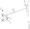
- FIG. 10is a view of a UAS attached to a tether.
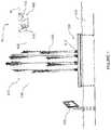
- FIG. 11is a view of a UAS attached to a tether configured with a water line and releasing a water stream.
- FIG. 12Ais a view of a UAS configured with a water container and releasing a water stream.
- FIG. 12Bis a view of a UAS configured with a water container and hovering.
- FIG. 12Cis a view of a UAS configured with a water container and submerging water container in a water basin.
- UAS 10may provide a movable lighting system located above the ground that may illuminate water displays or other structures from this elevated position.
- UAS 10may include a lighting system 100 that may include lighting assemblies 110 that may shine one or more beams of light 600 onto water stream 512 that may emanate from nozzle 510 of water display 500 .
- UAS 10 with lighting system 100 and lighting assembly 110may provide illumination to water stream 512 from unique perspectives and vantage points not attainable with ground-based lighting systems.
- UAS 10may shine light downwardly or in some other direction.
- UAS 10may be fitted with lighting 100 is further described in U.S. Provisional Ser. No. 62/067,978, the contents of which are incorporated by reference as if fully set forth herein.
- UAS lighting system 100may also shine one or more beams of light upon fog or water mist 516 that may exist in areas generally above and around water stream 512 , as well as on water droplets and water particles 514 that may generally fall from water stream 512 . Illuminating fog or mist 516 may provide an illuminated cloud effect, while illuminating water droplets 514 from above while they fall to the ground may result in a “raining light” visual effect.
- UAS lighting system 100may also direct beams of light into basin 518 of water display 500 , or onto other structures that may be a part of water display 500 such as reflective sign 520 , boats (not shown), characters (not shown) or other structures.
- FIG. 1shows a single UAS 10
- multiple UASs 10may alternatively be used. This preferably provides further enhancement by elevated lighting systems 100 .
- the one or more UASs 10may move as they shine light beam(s) 600 , which may also enhance the visual effects of display 500 .
- UASs 10 configured with lighting systems 100may also perform lighting shows that may shine light onto the audience or onto other targets. This may resemble lighting shows that may be experienced at musical concerts, e.g., light shows involving lasers. In this embodiment, it is preferred that only unharmful lasers or lights be used, i.e., those that do not cause damage to human eyes.
- water stream 512is depicted as a vertical water stream in FIG. 1 , it may be of any shape or type of water element such as a funnel, cone, fan, waterfall, water wall or other shape, and may be directed in any direction such as horizontal, at an angle or in other directions. Also, while the UAS 10 depicted in FIG. 1 as a multi-copter, other types of UASs may also be utilized.
- lighting assembly 110as shown in FIG. 1 is generally depicted as a directional lighting assembly such as a spotlight, a laser or other type of directional light source, other types of lights and assemblies may be utilized.
- lighting assembly 110may instead consist of a multi-directional light such as a bulb, a multi-directional array of LEDs or other type of light source.
- lighting assembly 110may comprise of multiple spotlights or lasers that may shine in different directions, or a combination of multi-directional lighting assemblies, directional lighting assemblies and other light sources.
- lighting assembly 110may shine light in a variety of directions including sideways, upward, downward or in any other direction.
- UAS lighting systems 100that utilize light sources that may cause damage to human eyes may also include controls to avoid pointing these light sources at observers. To this end, GPS and suitable software may control the orientation of UAS 10 and lighting system 100 . Also, lighting assembly 110 may comprise lights that shine white light, lights that shine colored light, or lights that shine a combination of white light and colored light. UAS lighting system 100 may be used in lieu of other types of lighting systems, independently of other types of lighting systems or in combination with other types of lighting systems, e.g., ground based lighting systems.
- Ground based lighting systemsare, by design, limited to illuminating a target from predefined vantage points that are limited by the design of the system. For example, a fixed ground based light may only illuminate a target from its physical position.
- a lighting system mounted to a carriage that my travel along a track or a wiremay illuminate a target only from the positions along the track or wire, but may not illuminate a target from any other positions that are beyond the track or wire.
- a rotatable lighting systemmay illuminate a target from any angle of rotation that is available to it, but cannot illuminate a target from any other location.
- UAS lighting system 100may illuminate a target from any location, height or angle to which UAS 10 may fly.
- UAS 10may be flown to a position that is vertically above fountain 500 such that lighting system 100 may shine a light downward to illuminate fountain stream 512 from above.
- UAS 10may be positioned at a different location, such as to the side of the same fountain stream 512 or to a different fountain stream 512 , such that it may illuminate fountain stream 512 from the side.
- these vantage pointsmay not need to be predetermined, and no mounts, platforms, tracks or wires need to be pre-designed and constructed as would be necessary for a ground based system to achieve the same lighting results.
- shining light at an object or feature of display 500such as water stream 512 , droplets 514 or mist 516 from different locations generally provides different visual effects. It is also preferred that decisions regarding the vantage points from which illumination occurs may be made in real-time by a show director, or from inputs or requests by remote operators, crowd consensus, online polling or any other suitable decision-making system. As such, the current invention provides for a dynamic and variable enhancement of the visual effects and expression provided by display 500 .
- UAS lighting system 100may continuously illuminate one or more fountain streams 512 , while UAS 10 maneuvers to different positions about display 500 .
- UAS 10 with lighting system 100may perform a spiral maneuver around a vertical fountain stream 512 , moving up and down while circling stream 512 , all the while illuminating the stream 512 .
- UAS 10may be piloted or programmed to provide this choreography. This represents an advance over ground based lighting systems which require construction of a physical track or intricate cabling system with lighting carriages around fountain stream 512 . These tracks or cables require additional money and time to design and construct, and the physical nature of such a ground based lighting system may block the view of the fountain from the audience thus diminishing the aesthetic effect of the overall fountain display 500 .
- UAS 10may fly close and/or also pass through water streams 512 , water particles 514 or water mist 516 as part of a choreographed lighting performance. As shown in FIG. 2 , lighted UASs 10 flying in proximity to water stream 512 may result in a dramatic and entertaining visual effect. In this situation, it may be preferable for UAS 10 to be configured with water resistant brushless motors that may be capable of providing thrust to UAS 10 without the need for elaborate waterproofing efforts. Other considerations relating to UASs 10 with lighting systems 100 flying directly through or in close proximity to water streams 512 are discussed in more detail below.
- water display 500may be illuminated by lighting systems positioned high above the ground and/or display 500 without the need for tall platforms, towers or other structures that would otherwise be needed to support elevated lighting.
- the ability to illuminate from high elevationsalso avoids the need to attach lighting to nearby buildings or other structures that may be nearby. And even if an existing structure such as a neighboring building were available to support lighting, the height, angle and position from which the lighting could illuminate water display 500 may be limited by the location and height of the building.
- the light beamwould degrade as the distance between the light source and display 500 increases. This in turn could limit the ability to adequately illuminate water display 500 or provide enhanced visual effects. Additionally, it may be desired to focus beams of light on separate in-line water streams 512 that may be intermittent or spaced separately or obstructed by other water streams from the line of sight position of the ground based light.
- UAS(s) 10as in the current invention preferably avoids the foregoing issues. As such, the current invention's use of UAS(s) 10 provides cost-savings, reduced logistical requirements, and greater flexibility to the manner in which lighting may be provided.
- the current inventionmay render display 500 relatively self-contained and/or transportable.
- UASs 10 and their lighting systems 100are not limited to the physical location of a neighboring building or dedicated light-support structure. Instead, UASs 10 and their lighting systems, including their power supplies are self-contained and require no design and construction of physical structures with associated power sources. Accordingly, to the extent that display 500 is intended to be packed up and transported to various locations, UASs 10 facilitate this capability.
- UASs 10 and their lighting systems 100provide additional advantages regarding the illumination of display 500 .
- no land need be purchased, leased or otherwise dedicated to a lighting system 100and no building or other land use permits associated with buildings or structures are required.
- no significant obstruction of view of water display 500will occur since no additional structures need be built.
- UASs 10configured with lighting systems 100 of the current invention may be employed to provide the elevated lighting necessary for the event at a budget and schedule within reason. Accordingly, as noted above, the current invention may facilitate display 500 traveling from city to city, thus eliminating the requirement to construct new ground based lighting systems, lease space or obtain legal building permits for such traveling events.
- UAS 10or a fleet of UASs 10 may be used with different displays 500 at various locations as desired.
- UASs 10may simultaneously illuminate water display 500 or other type of feature.
- multiple UASs 10each configured with lighting systems 100 , may be choreographed to illuminate water or other display features as part of the overall visual effect of display 500 .
- two UASs 10 with lighting systems 100may perform a spiral maneuver around a vertical fountain stream or streams 512 together.
- UASs 10may be positioned apart from each other by 180 degrees such that each UAS 10 may illuminate opposite sides of vertical water stream 512 during the maneuver, moving up and down while encircling and illuminating stream 512 .
- Each UAS lighting system 100may also utilize a different color of light thus adding to the visual effect.
- UASs 10may be used in the current invention and is not intended to limit the scope of the invention. Indeed, the manner in which UASs 10 may be used with or engage display 10 are almost limitless.
- UASs 10may perform entirely off the ground, they pose minimal obstruction of display 500 to the audience. This is a significant advance when considering the potential obstructions that would be posed by the tracks or wires with lighting carriages that would need to be constructed to provide this visual effect with a ground-based lighting system. While the above example described two UASs 10 used in combination, any number of UASs 10 may be used. In addition, multiple UASs 10 may be used to illuminate water display 500 independently of each other and not in a choreographed fashion.
- UAS lighting systems 100do not require the design and construction of ground based platforms or mounts, the use of UAS lighting systems 100 may allow for much greater flexibility in the modification of water streams 512 within water display 500 , as well as the illumination of these targets. For instance, if water display 500 were to be enlarged to include the addition of several newly built water elements 512 , there may be no need to design and construct new lighting systems to accommodate the modification since these new water streams 512 may be illuminated by a re-choreographed fleet of UAS lighting systems 100 .
- the illumination of water streams 512may be readily modified.
- the intensity of the illumination providedmay be adjusted to accommodate changes in the surroundings, e.g., where shadows are created by a newly-built neighboring building.
- the fleet of UAS lighting systems 100may be modified with no ground construction necessary.
- lighting assemblies 110may be changed to include a higher intensity light source, or another UAS lighting system 100 may be added to provide additional illumination.
- lighting system 100may be integrated into or otherwise attached to UAS 10 using mount(s) 700 .
- mount(s) 700may include brackets, bolts, locks, latches or other attachment means to secure and position lighting system 100 relative to UAS 10 .
- lighting system(s) 100may be connected to UAS body 12 and/or arm(s) 14 .
- lighting assemblies 110are preferably connected to UAS 10 so that lighting assembly 110 may shine light upon a desired target while UAS 10 flies, hovers or is located in a desired location(s).
- Mount 700may secure lighting system 100 and lighting assembly 110 in a fixed position or may allow lighting system 100 and lighting assembly 110 to be controllably moved side to side, up and down, at an angle, rotated about an axis or in any other direction. These movements may allow a target to be more precisely illuminated. This may also allow lighting system 100 to write words, create illustrations or produce other images on a surface.
- Controllable mount 700may be preprogrammed, manually controlled by the pilot of UAS 10 , controlled by an automated control system or controlled by other means.
- Each UAS 10 configured with lighting system 100may be controlled individually or in combination with other UAS lighting systems 100 by a pilot in real time, or by a computer or other type of automated controller. Aspects of UAS 10 and lighting system 100 that may be controlled may include: 1) the position and flight coordinates of each UAS 10 with respect to the illumination targets, other UASs 10 in the fleet and any other nearby structures, 2) the position and orientation of lighting system 100 with respect to UAS 10 and illumination targets, 3) the lighting sequences to illuminate the targets in relation to the position of each UAS 10 , 4) the position of UASs 10 in relation to observers for safety purposes and 5) any other aspect that may need to be controlled to allow the illumination of water display 500 by UAS lighting systems 100 .
- the flight of at least one UAS 10may be synchronized with the water 512 being shot out of at least one water fountain 500 .
- UAS(s) 10may include an onboard controller with software to control its flight, or software may be used in a controller that transmits control signals to UAS(s) 10 . Wherever this software resides, it may include pre-programmed choreography sequences to allow for fully automated shows to take place with minimal human intervention. Conversely, the software may allow for the manual orchestration of UAS lighting systems 100 . In addition, the software may allow for a combination of automated pre-programmed shows that may be manually altered or otherwise manually controlled in real time as desired. UASs 10 may include a GPS device so that its coordinates may be used by the software to control its next movements and to ensure UASs 10 remain in their intended flight path.
- UAS 10may include one or more cameras, transmitters or other mechanisms that may determine positional information and relay the physical location of UASs 10 to a computer or controller so that the ensuing movement of UAS 10 may be appropriately controlled.
- the GPS, camera or other means to determine locationmay act in a control loop to continuously or semi-continuously correct, adjust or alter the location or flight of UAS 10 .
- lighting system 100may be attached to UAS 10 using an extendable arm 720 .
- FIG. 5Adepicts extendable arm 720 in a generally retracted configuration
- FIG. 5Bdepicts extendable arm 720 in a generally extended configuration.
- Extendable armmay be preferred for certain UAS 10 maneuvers. For example, while UAS 10 may physically pass through water streams 512 , water particles 514 and/or water mist 516 without the threat of damage to UAS 10 or the disruption of its flying capabilities, it may be preferable for propellers 16 of UAS 10 to avoid physical contact with the foregoing.
- arm 720may be extended to allow light 100 to pass through stream(s) 512 , droplets 514 or mist 516 while propellers remain above. This may be desirable when, for example, light 110 is intended to fly through high velocity water streams 512 to avoid the force of these streams 512 disrupting the flying capabilities of UAS 10 or otherwise altering its position or course.
- UAS 10may be safely positioned near stream 512 , and then extend extendable arm 720 may be extended such that lighting system 100 may be moved to a position that is now closer to, or possibly in physical contact with, water steam 512 .
- arm 720may include segments 722 , 724 that may, for example, be nested together while in the retracted position of FIG. 5A , but which may extend and lengthen arm 720 in the extended position in FIG. 5B .
- Other means to lengthen arm 720may also be used.
- FIGS. 5A and 5Bdepict extendable arm 720 as extending in a generally downward direction
- extendable arm 720may extend in generally sideways direction, a generally upward direction or in any other direction. It should be noted that extended arm 720 may be in a retracted position as depicted in FIG. 5A for UAS 10 takeoff and landing such that lighting system 100 does not interfere with these operations.
- a benefit of extendable arm 720is that by positioning lighting system 100 closer to display 500 , the illumination of water stream 512 , droplets 514 or mist 516 may be higher in intensity and more vibrant in color due to the optical properties of light shining through water at close range, while still keeping distance between stream 512 and propellers 16 . In sum, enhanced lighting effect may be unachieved.
- UAS 10may be positioned directly above vertical water stream 512 and may lower lighting system 100 directly into the top portion of water stream 512 to illuminate it from within for a dramatic visual effect. UAS 10 may also hover or fly in a path that is just above the surface of water in water basin 518 such that lighting system 100 may be submerged into basin 518 , thus “painting” colored light onto the water's surface.
- Enabling lighting system 100 to come into physical contact with water of stream 512 , water droplets 514 or water mist 516may also provide the additional benefit of cooling lighting system 100 .
- lighting assembliesmay be submerged or in close proximity to the water in basin 518 of water display 500 and may be cooled by the water. These assemblies may also be submerged or in close proximity to water steams 512 or in the path of water particles 514 for cooling purposes as well.
- UAS lighting systems 100may also benefit from the cooling properties of the water display elements.
- extendable arm 720is depicted in FIG. 5B as telescoping, it may also extend through the use of foldable arms or sections, or may extend by other means. In addition, there may be configurations where the arm may not be extendable but instead may be of a fixed length and may still provide the benefits described above. For example, a balanced rod (not shown) may project from UAS 10 to position lighting assembly 110 into water stream 512 , water particles 514 , water mist 516 , water basin 518 or into other elements of fountain 500 .
- lighting system 100may be attached to UAS 10 by a retractable cable assembly 730 .
- FIG. 6Adepicts retractable cable assembly 730 in a generally retracted or recoiled configuration and
- FIG. 6Bdepicts retractable cable assembly 730 in a generally extended configuration.
- UAS 10 configured with retractable cable assembly 730may safely position itself beyond water stream 512 , and then may lower lighting system 100 by extending cables 732 of retractable cable assembly 730 such that lighting system 100 may be moved to a position that is closer to, or immersed in, water steam 512 .
- FIG. 6Bdepicts the use of three extendable cables 732 to secure and lower lighting system 100 but other numbers of cables or other tethers 732 may be used.
- FIG. 6Balso depicts the cables 732 configured in a straight line to support lighting system 100 , but other configurations may be utilized such as three cables that form a triangular cross-section, four cables that form a square cross-section or other configurations.
- Cables 732 of retractable cable assembly 730may be similar to each other or have different cross-sectional configurations. While FIG. 6B depicts three cables 732 generally parallel to each other, retractable cables 732 may be configured at different angles with respect to each other. As with extendable arm 720 , it may be preferable for retractable cable assembly 730 to be in a generally retracted or recoiled position as depicted in FIG. 6A for UAS 10 takeoff and landing such that lighting system 100 does not interfere with these operations. Alternatively, as with the operation of aircraft that tow banners and streamers, cables 732 may be laid out in careful order to enable takeoffs and landing, or snared and dropped by UASs 10 already in flight.
- retractable cable assembly 730may have the ability to lower lighting system 100 further down and away from the body 12 of UAS 10 when compared to extendable arm 720 . This may be due to fact that coiled cables may take up less physical space on a payload of UAS 10 compared to extendable sections of extendable arm 720 , and because of this, more length of coiled cables may be carried by UAS 10 .
- UAS 10may position itself vertically above water stream 512 and may lower lighting system 100 and lighting assembly 110 into the top of water stream 512 by uncoiling retractable cable assembly 730 . Because UAS 10 may be able to lower lighting system 100 to a greater distance below its body 12 , lighting system 100 and lighting assembly 110 may be lowered further into water stream 512 .
- UAS 10may be able to position itself high enough above water stream 512 to be generally out of the primary viewing area of the audience, and may lower lighting system 100 and lighting assembly 110 from the top of water stream 512 to a position generally towards the bottom of water stream 512 .
- lighting assembly 110comprise of a multidirectional light such that the outer circumference of water stream 512 may be illuminated evenly from the inside as lighting assembly 110 travels up and down the inside of water stream 512 . This may create a dramatic and entertaining water display effect that may be difficult to achieve with ground base lighting systems.
- extendable arm 720 and/or retractable cable assembly 730have the ability to position lighting systems 100 at varying distances from UAS 10 .
- lighting system 100be removable from UAS 10 so that it may be attached when needed and removed when not. This may allow UAS 10 to be fitted with the lighting system 100 for use in providing light to a water display 500 or other structure, and to then be utilized without lighting system 100 for other purposes.
- lighting system 100may be replaced with a releasable payload mounting system 716 as shown in FIGS. 7A and 7B .
- the removable payloadmay comprise many different types of items.
- the payloadmay comprise a light that is dropped from UAS 10 while in flight during a performance so that the falling light may form part of the overall performance of display 500 .
- the payloadmay be a pyrotechnic feature that ignites after being dropped during a performance.
- the payloadmay be a weighted object that is released so that it splashes in pool 518 of display 500 .
- payload mounting system 716may be programmed to disengage at a desired time in the performance as part of a choreographed event.
- payload system 716may be programmed to disengage when UAS 10 is located at a particular location defined by GPS coordinates and/or altitude.
- UAS 10may include a female mounting component that may be attached to body 12 or other component of UAS 10
- lighting system 100may include a male mounting component 712 .
- male component 712may be secured to female component 710 such that lighting system 100 may be securely attached to UAS 10 for use in lighting a water display as described above.
- male mount 712may be disengaged from female mount 710 so that lighting system 100 separates from UAS 10 as depicted in FIG. 7B . While this specification describes releasable mounting system 716 as having male and female components 712 , 710 , and while FIGS. 7A and 7B show mounting system 710 and mounting system 712 as female and male components, respectively, other releasable mounting systems 716 are within the scope of the current invention.
- mounting system 716component 710 need not be male and component 712 need not be female. Instead, their configurations may be reversed.
- mounting system 716may comprise other locking mechanisms, bolts, screws, latches and other components that may securely mate to each other and attach lighting system 100 to UAS 10 .
- other payloadsmay be securely attached to UAS 10 using similar mounting systems 716 for use with other applications.
- lighting system 100 with male mounting system 712may also be securely attached to a different UAS 10 configured with a female mounting system 710 .
- Releasable mounting system 716may also be utilized with extendable arm 720 depicted in FIGS. 5A and 5B , in the above embodiment regarding retractable cable assembly 730 depicted in FIGS. 6A and 6B , and/or in other embodiments described throughout this specification.
- extendable arm 720 configured with lighting system 100may be removably attached to UAS 10 utilizing releasable mounting system 716 as described above.
- retractable cable assembly 730 configured with lighting system 100may be removably attached to UAS 10 utilizing releasable mounting system 716 as well.
- lighting system 100may be removably attached to either extendable arm 720 or retractable cable assembly 730 in a similar manner.
- lighting system 100may be a fully self-contained item with rechargeable battery or power source and control systems, and thus allow for rapid swapping of depleted systems for fully charged electrical lighting units.
- UAS lighting system 100may include projector assembly 112 that may project images or video onto a target such as adjacent water stream 512 (e.g., FIGS. 1 and/or 8 ) or water curtain that forms water wall 518 within fountain 500 ( FIG. 8 ).
- UAS 10 configured with projector assembly 112may project an image or video onto water wall 518 such that the image or video may be viewable by an audience.
- adjacent water streams or wall 518comprise a waterfall, a funnel shaped stream or another type of water stream or water feature that may have a width sufficiently wide to allow an image or video to be projected onto it and be viewed by an audience.
- UAS 10 equipped with projector assembly 112may project images or video onto water wall 518 and an audience may view the images or video from generally the same side of water wall 518 . This may be similar to a movie theater where the audience and the projector are positioned on the same side of the viewing screen. In another configuration, an audience may be generally positioned on the opposite side of water wall 518 compared to UAS 10 such that images and video projected by projector assembly 112 may project onto and pass through water wall 518 such that they are viewable on the opposite side. Both of these configurations may add a very dramatic and exciting element to a lighted water display show.
- UAS 10 A with lighting system 100may shine light onto a separate UAS 10 B that may be configured with a “shadow puppet” shape 120 such that the shape 120 may cast a shadow onto a surface behind it such as a water wall 516 , water particles 514 , water fog 516 , a screen or other type of target or surface.
- Water wall 516may comprise a series of adjacent water streams 512 , a waterfall, a funnel shaped stream, or another type of water stream that may have a width sufficiently wide to allow the shadow cast by shape 120 onto water wall 516 to be viewable by an audience.
- FIG. 9depicts shadow puppet shape 120 as generally hanging below UAS 10
- shape 120may be positioned to the side, above or in any other position or configuration with UAS 10 .
- shape 120may be integrated with UAS 10 such that UAS 10 and shape 120 together may cast the shadow.
- shape 120may be a static shape as depicted in FIG. 9 , or may have the ability to dynamically change such that the shadow it may cast may also change.
- shape 120may change from the numerals that represent the current year to the shape of the numerals that represent the New Year. For instance, if the current year was 2014 and the New Year was 2015, shape 120 , and the shadow cast by shape 120 , may change from the numerals 2014 to the numerals 2015 to reflect the changing of the year.
- UAS 10may include tether 99 that may couple UAS 10 to a ground-based station 90 or operator. Tether 99 may provide safety by preventing UAS 10 from flying beyond areas deemed safe for UAS 10 or from simply flying off. For example, should UAS 10 malfunction and crash, tether 99 may be of a chosen length at any point in time during a light show that it may not allow UAS 10 to enter or otherwise crash into an area where an audience may exist.
- Tether 99may be shortened and/or lengthened in real time during the show to account for the position of UAS 10 such that UAS 10 does not enter an unsafe location.
- This controlmay be manual or may be provide by a computer or other type of controller.
- Tether 99may also provide power and other control signals to UAS 10 . This may eliminate the need for an on-board power source, or may avoid the need to recharge or replace batteries or other power sources that may be utilized by UAS 10 . Furthermore, the duty cycle of signal provided by tether 99 may remain constant.
- tether 99may be that it may allow UAS 10 to be fitted with more light assemblies 100 because no battery or other on-board power source may be needed. In other words, more light assemblies 100 may be added because the increase in weight they represent may be offset by the subtracted weight of the battery.
- Tether 99may also transmit electrical signals to control UAS 10 , as opposed to the radio frequency signals that are typically used with untethered UASs 10 . This is a benefit because radio signals may be interfered with by nearby electrical appliances and/or third parties. To this end, tether 99 allows two way communication between ground station 90 or operator, and UAS 10 . That is, tether 99 may also support signals from UAS 10 to the ground. Such signals may include position data and status of lights or other on-board appliances.
- UAS 10may weigh less than a specified amount to avoid being subject to otherwise pertinent regulations. This may eliminate restrictive regulations imposed by governmental agencies upon the commercial usage of drones. Such commercial UAS regulations may include the following: 1) the UASs may only be flown within the sight of the operator, 2) the UASs may only fly up to 100 miles per hour, 3) operators of the drones must be at least 17 years of age and 4) operators of the drones must pass an aeronautics test and be vetted by the Transportation Security Administration.
- UAS 10 depicted in FIG. 10may avoid the time and costs associated with addressing these restrictions.
- tether 99may include water line 98 that may run from a ground based water supply to UAS 10 .
- watermay be pumped from the ground to UAS 10 so that water may be launched into the air through water nozzle 96 configured with UAS 10 from a position off the ground.
- the resulting elevated water streams 514may create an exciting upside-down fountain effect.
- These streams 514may not necessarily be illuminated, or may be illuminated by lighting system 100 residing on the same UAS 10 that may be providing the off-the-ground water stream 514 , by a different lighting system 100 configured on a different UAS 10 , by a ground based lighting system or by other lighting means.
- Providing off-the-ground water streams 514may offer a whole new aesthetic dimension to the water stream features of water display 500 .
- UAS 10may be configured with bucket 94 , shovel or other type of container that may hold water and that may allow UAS 10 to carry and drop water from positions off the ground.
- Water container 94may be filled with water prior to take-off or may have the ability to refill as necessary by being submerged into water basin 518 as depicted in FIG. 12C , or be refilled by other water streams 512 (not shown) or other water sources.
- UAS 10configured with water container 94 may hover in the air while holding the water, and may then release the water into the air as depicted in FIG. 12A to form off the ground water stream 514 .
- water streams created by dropping watermay not necessarily be illuminated, or may be illuminated by lighting system 100 residing on the same UAS 10 that may be providing the off the ground water stream, by a different lighting system 100 configured on a different UAS 10 , by a ground based lighting system or by other lighting means.
- UAS 10may be configured to direct the generally downward stream of air that is created by its propellers 16 (often referred to as downwash or propwash) onto the water surface, into areas around water streams 512 , or to other areas, to clear any undesired fog or mist that may exist.
- UAS 10may include air rudders, channels, or other guide structures that may direct its propwash in a desired and controllable direction. UAS 10 may then be positioned such that its propwash may disperse fog or mist from water display 500 as necessary.
- UAS 10may be configured with an additional fan or air blower unit that may achieve the desired result.
- the propwash from UAS 10 or the air stream from an additional air blower unitmay be used to reshape water streams 512 mid-air, creating new shapes of blown water and mist.
- four UASs 10 positioned in equal quadrants around vertical water stream 512may each channel air streams into water steam 512 at a slightly upward angle in order to create upward shooting spikes of water and mist resulting in a “floating crown”.
- UASs 10may be configured with cameras and memory units to record and save images and video footage of water display 500 from perspectives and vantage points previously unattainable.
- UASs 10may also be configured with broadcast units to transmit recorded images or video to a ground station which may project the footage onto a screen or relay it to a large video monitor (such as a Jumbotron) to be viewed by an audience.
- UAS 10may have the ability to bypass ground station and broadcast recorded footage directly to a video monitor equipped with a receiver unit to display the footage to the audience in real time.
- footage from UAS 10 as described abovemay also be broadcast on the Internet in real time for audiences around the world to view.
- UAS 10configured with a camera, memory and broadcast capability may position itself directly above water display 500 while recording and broadcasting its footage. Video footage from this vantage point may then be displayed in real time onto a large screen that is viewable to the audience of water display 500 , as well as broadcast on the Internet to a global audience, thus giving both audiences a never before seen top-down perspective of water display 500 . It can be seen that such video footage or still images may also be recorded and stored for future viewing by similar or different audiences.
Landscapes
- Engineering & Computer Science (AREA)
- Physics & Mathematics (AREA)
- General Physics & Mathematics (AREA)
- Theoretical Computer Science (AREA)
- Business, Economics & Management (AREA)
- Accounting & Taxation (AREA)
- Marketing (AREA)
- Aviation & Aerospace Engineering (AREA)
- Non-Portable Lighting Devices Or Systems Thereof (AREA)
- Arrangement Of Elements, Cooling, Sealing, Or The Like Of Lighting Devices (AREA)
Abstract
Description
Claims (19)
Priority Applications (1)
| Application Number | Priority Date | Filing Date | Title |
|---|---|---|---|
| US15/393,113US11059601B2 (en) | 2015-12-28 | 2016-12-28 | Water and lighting displays including unmanned aerial system |
Applications Claiming Priority (2)
| Application Number | Priority Date | Filing Date | Title |
|---|---|---|---|
| US201562271775P | 2015-12-28 | 2015-12-28 | |
| US15/393,113US11059601B2 (en) | 2015-12-28 | 2016-12-28 | Water and lighting displays including unmanned aerial system |
Publications (2)
| Publication Number | Publication Date |
|---|---|
| US20170240296A1 US20170240296A1 (en) | 2017-08-24 |
| US11059601B2true US11059601B2 (en) | 2021-07-13 |
Family
ID=59225705
Family Applications (1)
| Application Number | Title | Priority Date | Filing Date |
|---|---|---|---|
| US15/393,113Expired - Fee RelatedUS11059601B2 (en) | 2015-12-28 | 2016-12-28 | Water and lighting displays including unmanned aerial system |
Country Status (2)
| Country | Link |
|---|---|
| US (1) | US11059601B2 (en) |
| WO (1) | WO2017117296A1 (en) |
Cited By (1)
| Publication number | Priority date | Publication date | Assignee | Title |
|---|---|---|---|---|
| US20220221029A1 (en)* | 2019-09-11 | 2022-07-14 | Alexandru Balan | 360° Advanced Rotation System |
Families Citing this family (12)
| Publication number | Priority date | Publication date | Assignee | Title |
|---|---|---|---|---|
| GB2557715B (en)* | 2017-02-28 | 2019-04-17 | Matthew Russell Iain | Unmanned aerial vehicles |
| US11217126B2 (en)* | 2017-12-28 | 2022-01-04 | Intel Corporation | Systems, methods and apparatus for self-coordinated drone based digital signage |
| CN207976680U (en)* | 2018-03-27 | 2018-10-16 | 深圳市大疆创新科技有限公司 | Light compensating lamp, holder and unmanned plane |
| CN108557097A (en)* | 2018-04-26 | 2018-09-21 | 广州市科锐达光电技术有限公司 | A kind of performance formation unmanned plane equipped with the illumination of LED wheel exterior feature |
| US20200039646A1 (en)* | 2018-08-06 | 2020-02-06 | Mark Fuller | Flying Gyroscope System and Method |
| US10723454B1 (en)* | 2019-08-09 | 2020-07-28 | Disney Enterprises, Inc. | Aerial show system using unmanned aerial vehicle (UAV) energy to animate creative show element |
| US11433417B2 (en)* | 2019-11-19 | 2022-09-06 | Royal Caribbean Cruises Ltd. | Water-based pyrotechnic illusion |
| JP7480636B2 (en)* | 2020-08-25 | 2024-05-10 | 株式会社Jvcケンウッド | Directional indicator |
| US11862052B2 (en)* | 2021-04-02 | 2024-01-02 | Ken-Ming Li | Water dance device with display screen effect |
| CN113173253A (en)* | 2021-05-20 | 2021-07-27 | 武汉理工大学 | Environment monitoring unmanned aerial vehicle's information acquisition device |
| US12169292B2 (en)* | 2022-05-18 | 2024-12-17 | Microavia International Limited | Display for laser projector |
| US20240199243A1 (en)* | 2022-11-09 | 2024-06-20 | Pavel Ruslanovich Andreev | System for visualizing image (variants), method for visualizing image (variants) and unmanned aerial vehicle |
Citations (83)
| Publication number | Priority date | Publication date | Assignee | Title |
|---|---|---|---|---|
| US3503574A (en) | 1966-05-27 | 1970-03-31 | Karl Eickmann | Fluid power operated vehicle groups |
| US4010619A (en) | 1976-05-24 | 1977-03-08 | The United States Of America As Represented By The Secretary Of The Navy | Remote unmanned work system (RUWS) electromechanical cable system |
| US5293304A (en) | 1992-06-08 | 1994-03-08 | Godfrey Engineering | Dual mode anticollision/recognition lamp for aircraft |
| US5769359A (en) | 1993-01-22 | 1998-06-23 | Freewing Aerial Robotics Corporation | Active feedback loop to control body pitch in STOL/VTOL free wing aircraft |
| US6200185B1 (en) | 1999-07-26 | 2001-03-13 | Dwight Trump Kuster, Jr. | Flying disc toy with displaying panel |
| US6270038B1 (en) | 1999-04-22 | 2001-08-07 | Sikorsky Aircraft Corporation | Unmanned aerial vehicle with counter-rotating ducted rotors and shrouded pusher-prop |
| US20020049728A1 (en) | 2000-07-03 | 2002-04-25 | Fuji Photo Film Co., Ltd. | Image distributing system |
| WO2002044809A1 (en) | 2000-11-30 | 2002-06-06 | Sky Media Airships, Inc. | Aerial image illumination system |
| US6547180B1 (en) | 2000-03-22 | 2003-04-15 | David Bernard Cassidy | Impeller-powered vertical takeoff and descent aircraft |
| US6575402B1 (en) | 2002-04-17 | 2003-06-10 | Sikorsky Aircraft Corporation | Cooling system for a hybrid aircraft |
| US20040020999A1 (en) | 2002-04-18 | 2004-02-05 | Beidokhti Noorolah Nader | Modular water fountain display |
| US6749154B1 (en) | 2002-10-29 | 2004-06-15 | Don Scott Johnson | Aircraft advertising system |
| US20050146884A1 (en) | 2004-01-07 | 2005-07-07 | Goodrich Hella Aerospace Lighting Systems Gmbh | Light, particularly a warning light, for a vehicle |
| US6933965B2 (en) | 2001-03-13 | 2005-08-23 | Tacshot, Inc. | Panoramic aerial imaging device |
| US20050219479A1 (en) | 2002-07-16 | 2005-10-06 | Markus Lenzenhuber And Daniel Peter Lenzenhuber | Image projection device that is able to float and to fly |
| WO2006016018A1 (en) | 2004-06-04 | 2006-02-16 | Bertin Technologies | Vertical take-off and landing miniature drone |
| US7055994B2 (en) | 2000-09-19 | 2006-06-06 | L-3 Communications Corporation | Light source assembly and methods for aircraft external lighting |
| US20060140644A1 (en) | 2004-12-23 | 2006-06-29 | Paolella Arthur C | High performance, high efficiency fiber optic link for analog and RF systems |
| US7082706B1 (en) | 2001-06-05 | 2006-08-01 | Skytypers, Inc. | Systems and methods for creating aerial messages |
| US7249732B2 (en) | 2002-01-07 | 2007-07-31 | Ufoz, Llc | Aerodynamically stable, VTOL aircraft |
| WO2007141795A1 (en) | 2006-06-08 | 2007-12-13 | Israel Aerospace Industries Ltd. | Unmanned air vehicle system |
| US7324016B1 (en) | 2005-11-22 | 2008-01-29 | The United States Of America As Represented By The Secretary Of The Navy | Navigational indicating system for rotary wing aircraft |
| US20080165547A1 (en) | 2005-03-08 | 2008-07-10 | Grant Harold Amor | Led Lighting Apparatus in a Plastic Housing |
| KR20080074045A (en) | 2007-02-07 | 2008-08-12 | 엔이씨 라이팅 가부시키가이샤 | Ceiling fan with swivel blade side light |
| US7414546B2 (en) | 2004-07-08 | 2008-08-19 | Honeywell International Inc. | White anti-collision light utilizing light-emitting diode (LED) technology |
| US20080313937A1 (en) | 2007-06-20 | 2008-12-25 | Boyce Mark A | Aerial image projection system and method of utilizing same |
| US7472866B2 (en) | 2006-11-15 | 2009-01-06 | The United States Of America As Represented By The Secretary Of The Navy | Deployment system and method for subsurface launched unmanned aerial vehicle |
| US7631834B1 (en) | 2006-02-24 | 2009-12-15 | Stealth Robotics, Llc | Aerial robot with dispensable conductive filament |
| US20100027281A1 (en) | 2008-07-31 | 2010-02-04 | Waters Stanley E | LED Anti-Collision Light for Commercial Aircraft |
| US7668403B2 (en) | 2005-06-28 | 2010-02-23 | Lockheed Martin Corporation | Frame grabber |
| DE202009017291U1 (en) | 2009-12-20 | 2010-03-25 | Vogelstätter, Harald | Aircraft model, housing part for an aircraft model and device for guiding cooling air |
| KR20100041367A (en) | 2008-10-14 | 2010-04-22 | 김대수 | Lighting fixture of light emitting diode |
| US20110180667A1 (en) | 2009-03-10 | 2011-07-28 | Honeywell International Inc. | Tether energy supply system |
| KR20110090231A (en) | 2010-02-03 | 2011-08-10 | (주)셈투유 | Video output device using fractional screen |
| US8056461B2 (en) | 2007-09-18 | 2011-11-15 | Raytheon Company | Methods and apparatus for marine deployment |
| US8109711B2 (en) | 2008-07-18 | 2012-02-07 | Honeywell International Inc. | Tethered autonomous air vehicle with wind turbines |
| US20120044710A1 (en)* | 2010-08-17 | 2012-02-23 | Jones Kenneth R | Aerially Deployed Illumination System |
| US8123460B2 (en) | 2008-07-23 | 2012-02-28 | Honeywell International Inc. | UAV pod cooling using integrated duct wall heat transfer |
| US20120056041A1 (en) | 2010-09-02 | 2012-03-08 | Dream Space World Corporation | Unmanned Flying Vehicle Made With PCB |
| US8157383B2 (en) | 2008-10-01 | 2012-04-17 | The United States Of America As Represented By The Secretary Of The Army | System for displaying images and/or information on aircraft blades and method thereof |
| US20120112008A1 (en) | 2010-08-16 | 2012-05-10 | Primal Innovation | System for high altitude tethered powered flight platform |
| US20120153087A1 (en) | 2008-08-06 | 2012-06-21 | Honeywell International Inc. | Modular Pods for Use with an Unmanned Aerial Vehicle |
| US20120200703A1 (en) | 2009-10-22 | 2012-08-09 | Bluebird Aero Systems Ltd. | Imaging system for uav |
| JP2012190557A (en) | 2011-03-08 | 2012-10-04 | Panasonic Corp | Illumination apparatus, and fan unit for illumination apparatus |
| US20120250335A1 (en) | 2011-03-08 | 2012-10-04 | Panasonic Corporation | Illumination apparatus and fan unit for illumination apparatus |
| US8369399B2 (en) | 2006-02-13 | 2013-02-05 | Sony Corporation | System and method to combine multiple video streams |
| US20130062457A1 (en) | 2010-03-23 | 2013-03-14 | Athene Works Limited | Aerial Vehicle and Method of Flight |
| US20130077330A1 (en) | 2011-09-26 | 2013-03-28 | Goodrich Lighting Systems Gmbh | Aircraft Light for Emitting Light in a Desired Spatial Angular Region and with a Desired Light Distribution |
| US20130134254A1 (en) | 2011-11-29 | 2013-05-30 | Jason Moore | UAV Fire-fighting System |
| CN103241377A (en) | 2013-05-27 | 2013-08-14 | 襄阳宏伟航空器有限责任公司 | Soft-wing unmanned aerocraft with automatic fog dispersal function |
| US8511828B2 (en)* | 2010-06-29 | 2013-08-20 | Wet Enterprises, Inc. | Image projection on dynamic water mist screen |
| US20130233964A1 (en) | 2012-03-07 | 2013-09-12 | Aurora Flight Sciences Corporation | Tethered aerial system for data gathering |
| US20130248097A1 (en) | 2012-03-21 | 2013-09-26 | Richard S. PLOSS, JR. | Material Trivial Transfer Graphene |
| US8554395B2 (en) | 2008-12-15 | 2013-10-08 | Saab Ab | Method and system for facilitating autonomous landing of aerial vehicles on a surface |
| JP2013211200A (en) | 2012-03-30 | 2013-10-10 | Mitsubishi Chemicals Corp | Lighting device |
| US8567718B1 (en) | 1999-07-23 | 2013-10-29 | Advanced Aerospace Technologies, Inc. | Launch and recovery system for unmanned aerial vehicles |
| WO2013162128A1 (en) | 2012-04-24 | 2013-10-31 | 유콘시스템 주식회사 | Cable connection unmanned aerial vehicle system |
| CN203294314U (en) | 2013-05-27 | 2013-11-20 | 襄阳宏伟航空器有限责任公司 | Gentle wing unmanned aerial vehicle with automatic fog dissipation function |
| US20130314502A1 (en)* | 2012-05-22 | 2013-11-28 | Julian Michael Urbach | Portable mobile light stage |
| US8596572B1 (en) | 2009-08-07 | 2013-12-03 | The Boeing Company | Solar powered radiometric lift device |
| US8600602B1 (en) | 2009-07-06 | 2013-12-03 | Honeywell International Inc. | Flight technical control management for an unmanned aerial vehicle |
| US20140002990A1 (en) | 2012-06-29 | 2014-01-02 | General Electric Company | Thermal management in optical and electronic devices |
| US20140018976A1 (en) | 2012-07-13 | 2014-01-16 | Honeywell International Inc. | System and method for unmanned system data collection, management, and reporting |
| US8646719B2 (en) | 2010-08-23 | 2014-02-11 | Heliplane, Llc | Marine vessel-towable aerovehicle system with automated tow line release |
| US20140131510A1 (en) | 2012-11-15 | 2014-05-15 | SZ DJI Technology Co., Ltd | Unmanned aerial vehicle and operations thereof |
| US8777157B2 (en) | 2008-10-31 | 2014-07-15 | University Of Kansas | Tethered hovering platform |
| US20140217242A1 (en) | 2011-03-28 | 2014-08-07 | Prox Dynamics As | Uav kit |
| US20140231590A1 (en) | 2013-02-15 | 2014-08-21 | Disney Enterprises, Inc. | Aerial display system with marionettes articulated and supported by airborne devices |
| US20140236388A1 (en)* | 2013-02-15 | 2014-08-21 | Disney Enterprises, Inc. | Aerial display system with floating pixels |
| US20140233099A1 (en) | 2013-02-15 | 2014-08-21 | Disney Enterprises, Inc. | Aerial display system with floating projection screens |
| US20140257595A1 (en) | 2013-03-05 | 2014-09-11 | Navteq B.V. | Aerial image collection |
| US20140268838A1 (en) | 2013-03-13 | 2014-09-18 | Roger Kimball | Model airplane illumination system |
| US20140263852A1 (en) | 2013-03-15 | 2014-09-18 | CyPhy Works, Inc. | Spooler for unmanned aerial vehicle system |
| US20150129716A1 (en) | 2012-05-16 | 2015-05-14 | Meir Yoffe | Point Take-Off and Landing of Unmanned Flying Objects |
| US20150154890A1 (en) | 2013-09-23 | 2015-06-04 | SonoSim, Inc. | System and Method for Augmented Ultrasound Simulation using Flexible Touch Sensitive Surfaces |
| US9174733B1 (en)* | 2014-08-28 | 2015-11-03 | Google Inc. | Payload-release device and operation thereof |
| US20150362917A1 (en) | 2014-06-13 | 2015-12-17 | Twitter, Inc. | Messaging-enabled unmanned aerial vehicle |
| US20160033855A1 (en) | 2014-07-31 | 2016-02-04 | Disney Enterprises, Inc. | Projection assemblies for use with unmanned aerial vehicles |
| US20160041628A1 (en)* | 2014-07-30 | 2016-02-11 | Pramod Kumar Verma | Flying user interface |
| US20160068266A1 (en) | 2014-02-27 | 2016-03-10 | David W. Carroll | Rotary propeller drone with integrated power storage |
| US20160200437A1 (en) | 2015-01-12 | 2016-07-14 | Mark Andrew Ryan | Tethered Flight Control System for Small Unmanned Aircraft |
| US10364026B1 (en) | 2015-09-21 | 2019-07-30 | Amazon Technologies, Inc. | Track and tether vehicle position estimation |
| US10384777B1 (en) | 2015-02-27 | 2019-08-20 | Amazon Technologies, Inc. | Tethering system for unmanned aerial vehicles |
- 2016
- 2016-12-28WOPCT/US2016/069024patent/WO2017117296A1/ennot_activeCeased
- 2016-12-28USUS15/393,113patent/US11059601B2/ennot_activeExpired - Fee Related
Patent Citations (92)
| Publication number | Priority date | Publication date | Assignee | Title |
|---|---|---|---|---|
| US3503574A (en) | 1966-05-27 | 1970-03-31 | Karl Eickmann | Fluid power operated vehicle groups |
| US4010619A (en) | 1976-05-24 | 1977-03-08 | The United States Of America As Represented By The Secretary Of The Navy | Remote unmanned work system (RUWS) electromechanical cable system |
| US5293304A (en) | 1992-06-08 | 1994-03-08 | Godfrey Engineering | Dual mode anticollision/recognition lamp for aircraft |
| US5769359A (en) | 1993-01-22 | 1998-06-23 | Freewing Aerial Robotics Corporation | Active feedback loop to control body pitch in STOL/VTOL free wing aircraft |
| US6270038B1 (en) | 1999-04-22 | 2001-08-07 | Sikorsky Aircraft Corporation | Unmanned aerial vehicle with counter-rotating ducted rotors and shrouded pusher-prop |
| US8567718B1 (en) | 1999-07-23 | 2013-10-29 | Advanced Aerospace Technologies, Inc. | Launch and recovery system for unmanned aerial vehicles |
| US20150329218A1 (en) | 1999-07-23 | 2015-11-19 | Advanced Aerospace Technologies, Inc. | Launch and recovery system for unmanned aerial vehicles |
| US6200185B1 (en) | 1999-07-26 | 2001-03-13 | Dwight Trump Kuster, Jr. | Flying disc toy with displaying panel |
| US6547180B1 (en) | 2000-03-22 | 2003-04-15 | David Bernard Cassidy | Impeller-powered vertical takeoff and descent aircraft |
| US20020049728A1 (en) | 2000-07-03 | 2002-04-25 | Fuji Photo Film Co., Ltd. | Image distributing system |
| US7055994B2 (en) | 2000-09-19 | 2006-06-06 | L-3 Communications Corporation | Light source assembly and methods for aircraft external lighting |
| US20020171927A1 (en) | 2000-11-30 | 2002-11-21 | Barnes Alfred C. | Aerial image illumination system |
| WO2002044809A1 (en) | 2000-11-30 | 2002-06-06 | Sky Media Airships, Inc. | Aerial image illumination system |
| US6933965B2 (en) | 2001-03-13 | 2005-08-23 | Tacshot, Inc. | Panoramic aerial imaging device |
| US7082706B1 (en) | 2001-06-05 | 2006-08-01 | Skytypers, Inc. | Systems and methods for creating aerial messages |
| US7249732B2 (en) | 2002-01-07 | 2007-07-31 | Ufoz, Llc | Aerodynamically stable, VTOL aircraft |
| US6575402B1 (en) | 2002-04-17 | 2003-06-10 | Sikorsky Aircraft Corporation | Cooling system for a hybrid aircraft |
| US20040020999A1 (en) | 2002-04-18 | 2004-02-05 | Beidokhti Noorolah Nader | Modular water fountain display |
| US20050219479A1 (en) | 2002-07-16 | 2005-10-06 | Markus Lenzenhuber And Daniel Peter Lenzenhuber | Image projection device that is able to float and to fly |
| US6749154B1 (en) | 2002-10-29 | 2004-06-15 | Don Scott Johnson | Aircraft advertising system |
| US20050146884A1 (en) | 2004-01-07 | 2005-07-07 | Goodrich Hella Aerospace Lighting Systems Gmbh | Light, particularly a warning light, for a vehicle |
| WO2006016018A1 (en) | 2004-06-04 | 2006-02-16 | Bertin Technologies | Vertical take-off and landing miniature drone |
| US7414546B2 (en) | 2004-07-08 | 2008-08-19 | Honeywell International Inc. | White anti-collision light utilizing light-emitting diode (LED) technology |
| US20060140644A1 (en) | 2004-12-23 | 2006-06-29 | Paolella Arthur C | High performance, high efficiency fiber optic link for analog and RF systems |
| US20080165547A1 (en) | 2005-03-08 | 2008-07-10 | Grant Harold Amor | Led Lighting Apparatus in a Plastic Housing |
| US7668403B2 (en) | 2005-06-28 | 2010-02-23 | Lockheed Martin Corporation | Frame grabber |
| US7324016B1 (en) | 2005-11-22 | 2008-01-29 | The United States Of America As Represented By The Secretary Of The Navy | Navigational indicating system for rotary wing aircraft |
| US8369399B2 (en) | 2006-02-13 | 2013-02-05 | Sony Corporation | System and method to combine multiple video streams |
| US7631834B1 (en) | 2006-02-24 | 2009-12-15 | Stealth Robotics, Llc | Aerial robot with dispensable conductive filament |
| WO2007141795A1 (en) | 2006-06-08 | 2007-12-13 | Israel Aerospace Industries Ltd. | Unmanned air vehicle system |
| US7472866B2 (en) | 2006-11-15 | 2009-01-06 | The United States Of America As Represented By The Secretary Of The Navy | Deployment system and method for subsurface launched unmanned aerial vehicle |
| KR20080074045A (en) | 2007-02-07 | 2008-08-12 | 엔이씨 라이팅 가부시키가이샤 | Ceiling fan with swivel blade side light |
| US8100649B2 (en) | 2007-02-07 | 2012-01-24 | Nec Lighting, Ltd. | Ceiling fan with rotary blade surface light |
| US8091822B2 (en) | 2007-06-20 | 2012-01-10 | Boyce Mark A | Aerial image projection system and method of utilizing same |
| US20080313937A1 (en) | 2007-06-20 | 2008-12-25 | Boyce Mark A | Aerial image projection system and method of utilizing same |
| US8056461B2 (en) | 2007-09-18 | 2011-11-15 | Raytheon Company | Methods and apparatus for marine deployment |
| US8109711B2 (en) | 2008-07-18 | 2012-02-07 | Honeywell International Inc. | Tethered autonomous air vehicle with wind turbines |
| US8123460B2 (en) | 2008-07-23 | 2012-02-28 | Honeywell International Inc. | UAV pod cooling using integrated duct wall heat transfer |
| US20100027281A1 (en) | 2008-07-31 | 2010-02-04 | Waters Stanley E | LED Anti-Collision Light for Commercial Aircraft |
| US20120153087A1 (en) | 2008-08-06 | 2012-06-21 | Honeywell International Inc. | Modular Pods for Use with an Unmanned Aerial Vehicle |
| US8157383B2 (en) | 2008-10-01 | 2012-04-17 | The United States Of America As Represented By The Secretary Of The Army | System for displaying images and/or information on aircraft blades and method thereof |
| KR20100041367A (en) | 2008-10-14 | 2010-04-22 | 김대수 | Lighting fixture of light emitting diode |
| US8777157B2 (en) | 2008-10-31 | 2014-07-15 | University Of Kansas | Tethered hovering platform |
| US8554395B2 (en) | 2008-12-15 | 2013-10-08 | Saab Ab | Method and system for facilitating autonomous landing of aerial vehicles on a surface |
| US20110180667A1 (en) | 2009-03-10 | 2011-07-28 | Honeywell International Inc. | Tether energy supply system |
| US8600602B1 (en) | 2009-07-06 | 2013-12-03 | Honeywell International Inc. | Flight technical control management for an unmanned aerial vehicle |
| US8596572B1 (en) | 2009-08-07 | 2013-12-03 | The Boeing Company | Solar powered radiometric lift device |
| US20120200703A1 (en) | 2009-10-22 | 2012-08-09 | Bluebird Aero Systems Ltd. | Imaging system for uav |
| DE202009017291U1 (en) | 2009-12-20 | 2010-03-25 | Vogelstätter, Harald | Aircraft model, housing part for an aircraft model and device for guiding cooling air |
| KR20110090231A (en) | 2010-02-03 | 2011-08-10 | (주)셈투유 | Video output device using fractional screen |
| US20130062457A1 (en) | 2010-03-23 | 2013-03-14 | Athene Works Limited | Aerial Vehicle and Method of Flight |
| US8511828B2 (en)* | 2010-06-29 | 2013-08-20 | Wet Enterprises, Inc. | Image projection on dynamic water mist screen |
| US20120112008A1 (en) | 2010-08-16 | 2012-05-10 | Primal Innovation | System for high altitude tethered powered flight platform |
| US8434920B2 (en) | 2010-08-17 | 2013-05-07 | Kenneth R Jones | Aerially deployed illumination system |
| US20120044710A1 (en)* | 2010-08-17 | 2012-02-23 | Jones Kenneth R | Aerially Deployed Illumination System |
| US8646719B2 (en) | 2010-08-23 | 2014-02-11 | Heliplane, Llc | Marine vessel-towable aerovehicle system with automated tow line release |
| US20120056041A1 (en) | 2010-09-02 | 2012-03-08 | Dream Space World Corporation | Unmanned Flying Vehicle Made With PCB |
| JP2012190557A (en) | 2011-03-08 | 2012-10-04 | Panasonic Corp | Illumination apparatus, and fan unit for illumination apparatus |
| US20120250335A1 (en) | 2011-03-08 | 2012-10-04 | Panasonic Corporation | Illumination apparatus and fan unit for illumination apparatus |
| US20140217242A1 (en) | 2011-03-28 | 2014-08-07 | Prox Dynamics As | Uav kit |
| US20130077330A1 (en) | 2011-09-26 | 2013-03-28 | Goodrich Lighting Systems Gmbh | Aircraft Light for Emitting Light in a Desired Spatial Angular Region and with a Desired Light Distribution |
| US20130134254A1 (en) | 2011-11-29 | 2013-05-30 | Jason Moore | UAV Fire-fighting System |
| US20130233964A1 (en) | 2012-03-07 | 2013-09-12 | Aurora Flight Sciences Corporation | Tethered aerial system for data gathering |
| US20130248097A1 (en) | 2012-03-21 | 2013-09-26 | Richard S. PLOSS, JR. | Material Trivial Transfer Graphene |
| JP2013211200A (en) | 2012-03-30 | 2013-10-10 | Mitsubishi Chemicals Corp | Lighting device |
| WO2013162128A1 (en) | 2012-04-24 | 2013-10-31 | 유콘시스템 주식회사 | Cable connection unmanned aerial vehicle system |
| US20150129716A1 (en) | 2012-05-16 | 2015-05-14 | Meir Yoffe | Point Take-Off and Landing of Unmanned Flying Objects |
| US20130314502A1 (en)* | 2012-05-22 | 2013-11-28 | Julian Michael Urbach | Portable mobile light stage |
| US20140002990A1 (en) | 2012-06-29 | 2014-01-02 | General Electric Company | Thermal management in optical and electronic devices |
| US20140018976A1 (en) | 2012-07-13 | 2014-01-16 | Honeywell International Inc. | System and method for unmanned system data collection, management, and reporting |
| US20140131510A1 (en) | 2012-11-15 | 2014-05-15 | SZ DJI Technology Co., Ltd | Unmanned aerial vehicle and operations thereof |
| US8825225B1 (en) | 2013-02-15 | 2014-09-02 | Disney Enterprises, Inc. | Aerial display system with floating projection screens |
| US9169030B2 (en)* | 2013-02-15 | 2015-10-27 | Disney Enterprises, Inc. | Aerial display system with floating pixels |
| US20140233099A1 (en) | 2013-02-15 | 2014-08-21 | Disney Enterprises, Inc. | Aerial display system with floating projection screens |
| US20140231590A1 (en) | 2013-02-15 | 2014-08-21 | Disney Enterprises, Inc. | Aerial display system with marionettes articulated and supported by airborne devices |
| US20140236388A1 (en)* | 2013-02-15 | 2014-08-21 | Disney Enterprises, Inc. | Aerial display system with floating pixels |
| US8862285B2 (en) | 2013-02-15 | 2014-10-14 | Disney Enterprises, Inc. | Aerial display system with floating pixels |
| US20140374535A1 (en) | 2013-02-15 | 2014-12-25 | Disney Enterprises, Inc. | Aerial display system with floating pixels |
| US20140257595A1 (en) | 2013-03-05 | 2014-09-11 | Navteq B.V. | Aerial image collection |
| US20140268838A1 (en) | 2013-03-13 | 2014-09-18 | Roger Kimball | Model airplane illumination system |
| US20140263852A1 (en) | 2013-03-15 | 2014-09-18 | CyPhy Works, Inc. | Spooler for unmanned aerial vehicle system |
| CN103241377A (en) | 2013-05-27 | 2013-08-14 | 襄阳宏伟航空器有限责任公司 | Soft-wing unmanned aerocraft with automatic fog dispersal function |
| CN203294314U (en) | 2013-05-27 | 2013-11-20 | 襄阳宏伟航空器有限责任公司 | Gentle wing unmanned aerial vehicle with automatic fog dissipation function |
| US20150154890A1 (en) | 2013-09-23 | 2015-06-04 | SonoSim, Inc. | System and Method for Augmented Ultrasound Simulation using Flexible Touch Sensitive Surfaces |
| US20160068266A1 (en) | 2014-02-27 | 2016-03-10 | David W. Carroll | Rotary propeller drone with integrated power storage |
| US20150362917A1 (en) | 2014-06-13 | 2015-12-17 | Twitter, Inc. | Messaging-enabled unmanned aerial vehicle |
| US20160041628A1 (en)* | 2014-07-30 | 2016-02-11 | Pramod Kumar Verma | Flying user interface |
| US20160033855A1 (en) | 2014-07-31 | 2016-02-04 | Disney Enterprises, Inc. | Projection assemblies for use with unmanned aerial vehicles |
| US9174733B1 (en)* | 2014-08-28 | 2015-11-03 | Google Inc. | Payload-release device and operation thereof |
| US20160200437A1 (en) | 2015-01-12 | 2016-07-14 | Mark Andrew Ryan | Tethered Flight Control System for Small Unmanned Aircraft |
| US10384777B1 (en) | 2015-02-27 | 2019-08-20 | Amazon Technologies, Inc. | Tethering system for unmanned aerial vehicles |
| US10364026B1 (en) | 2015-09-21 | 2019-07-30 | Amazon Technologies, Inc. | Track and tether vehicle position estimation |
Non-Patent Citations (13)
| Title |
|---|
| "Heat Transport by Radiation", U.S. Appl. No. 14/922,061, filed Feb. 9, 2017 Office Action, dated May 2010, 3 pages. |
| "Phantom 2 User Manual V1.1," Apr. 30, 2014, 2013-2014 DJI Innovations, 34 pages, U.S. Appl. No. 14/922,061, filed Feb. 9, 2017 Office Action. |
| "Spreading Wings S900 User Manual", Aug. 2014, 2014 DJI, 32 pages, U.S. Appl. No. 14/922,061, filed Feb. 9, 2017 Office Action. |
| Burkhart, Ford; DSS 2013: Tiny Drone Flies on Fiber-Optic Power; the business of photonics optics.org; http://optics.org/news; May 2, 2013; 2 pages. |
| Eurolink Systems; Cobra—Micro Tethered Surveillance; ERMES by EuroLink Systems, ERMES Technologies; Oct. 21, 2014, 3 pages. |
| Finch, Andy and Ballew, Eric; Direct Spray Cooling and System-Level Comparisons; Electronics Cooling Magazine; www.electronics-cooling.com; Aug. 1, 2009; 5 pages. |
| Lai, Yan, et al., "Liquid Cooling of Bright LEDs for Automotive Applications", 2009, Applied Thermal Engineering 29 (2009), pp. 1239-1244, U.S. Appl. No. 14/922,061, filed Feb. 9, 2017 Office Action. |
| LEDs Magazine; Oxley Supplies LED Lights to BAE Unmanned Air Vehicle; www.ledsmagazine.com; Oct. 17, 2014; 11 pages. |
| PCT, International Search Report and Written Opinion of the International Searching Authority, PCT/US2015/057249, dated Feb. 17, 2016, 10 pages. |
| Quick, Darren; CyPhy Works' UAVs Use Ground-Based Power to Stay Aloft Indefinitely; www.gizmag.com, Dec. 5, 2012, 4 pages. |
| Staes, Patrick; Drone @ Work; Aerial Imaging and Filming; http://drone-at-work.com; Oct. 21, 2014, 6 pages. |
| Vila, Oscar; [Power Electronics 01] Design of the Power Electronics of a Tethered UAV; Master Thesis; Bio, Electro and Mechanical Systems, http://beams.ulb.ac.be/student-projects; Oct. 20, 2014; 2 pages. |
| Wang, Ruishan, et al., "A Cooling System with a Fan for Thermal Management of High-Power LEDs", Aug. 2010, J. Mod. Phys., 2010, 1, pp. 196-199, U.S. Appl. No. 14/922,061, filed Feb. 9, 2017 Office Action. |
Cited By (2)
| Publication number | Priority date | Publication date | Assignee | Title |
|---|---|---|---|---|
| US20220221029A1 (en)* | 2019-09-11 | 2022-07-14 | Alexandru Balan | 360° Advanced Rotation System |
| US11821338B2 (en)* | 2019-09-11 | 2023-11-21 | Alexandru Balan | 360° advanced rotation system |
Also Published As
| Publication number | Publication date |
|---|---|
| US20170240296A1 (en) | 2017-08-24 |
| WO2017117296A1 (en) | 2017-07-06 |
Similar Documents
| Publication | Publication Date | Title |
|---|---|---|
| US11059601B2 (en) | Water and lighting displays including unmanned aerial system | |
| US10696395B2 (en) | Tethered unmanned aerial system | |
| US10068506B2 (en) | System, device for creating an aerial image | |
| CN109460066B (en) | Virtual reality system for an aircraft | |
| US11780565B2 (en) | Rotary wing aircraft | |
| US11064184B2 (en) | Aerial vehicle imaging and targeting system | |
| US10109224B1 (en) | Methods and devices for using aerial vehicles to create graphic displays and reconfigurable 3D structures | |
| NL1040863B1 (en) | Method and systems for airborne visualization. | |
| US9169030B2 (en) | Aerial display system with floating pixels | |
| US10745126B2 (en) | Unmanned aerial system with transportable screen | |
| CN107115687B (en) | Multidimensional acousto-optic stage system based on unmanned aerial vehicle aircraft carrier | |
| KR102160416B1 (en) | Drone | |
| JP2019060589A (en) | Aerial vehicle interception system | |
| JP6525145B2 (en) | Emitting point figure pattern display system using a flying object, a method of displaying a light emitting point figure pattern, and a flying object used for the system and method | |
| US12404036B2 (en) | Systems and methods for tethered drones | |
| CN204415732U (en) | A kind of aerial mobile film projection unmanned plane | |
| US20200201331A1 (en) | A system for controlling unmanned aerial vehicles in a flight formation in order to film a moving object using several cameras | |
| US20190291893A1 (en) | Unmanned aircraft and system for generating an image in the airspace | |
| KR102614743B1 (en) | A drone for performance | |
| KR102162944B1 (en) | Drone | |
| JP2019078915A (en) | Rainbow generation method and rainbow generation system |
Legal Events
| Date | Code | Title | Description |
|---|---|---|---|
| STPP | Information on status: patent application and granting procedure in general | Free format text:DOCKETED NEW CASE - READY FOR EXAMINATION | |
| STPP | Information on status: patent application and granting procedure in general | Free format text:NON FINAL ACTION MAILED | |
| STPP | Information on status: patent application and granting procedure in general | Free format text:RESPONSE TO NON-FINAL OFFICE ACTION ENTERED AND FORWARDED TO EXAMINER | |
| STPP | Information on status: patent application and granting procedure in general | Free format text:FINAL REJECTION MAILED | |
| STPP | Information on status: patent application and granting procedure in general | Free format text:NON FINAL ACTION MAILED | |
| STPP | Information on status: patent application and granting procedure in general | Free format text:RESPONSE TO NON-FINAL OFFICE ACTION ENTERED AND FORWARDED TO EXAMINER | |
| STPP | Information on status: patent application and granting procedure in general | Free format text:NOTICE OF ALLOWANCE MAILED -- APPLICATION RECEIVED IN OFFICE OF PUBLICATIONS | |
| STPP | Information on status: patent application and granting procedure in general | Free format text:AWAITING TC RESP., ISSUE FEE NOT PAID | |
| STPP | Information on status: patent application and granting procedure in general | Free format text:NOTICE OF ALLOWANCE MAILED -- APPLICATION RECEIVED IN OFFICE OF PUBLICATIONS | |
| STPP | Information on status: patent application and granting procedure in general | Free format text:PUBLICATIONS -- ISSUE FEE PAYMENT RECEIVED | |
| STPP | Information on status: patent application and granting procedure in general | Free format text:PUBLICATIONS -- ISSUE FEE PAYMENT VERIFIED | |
| STCF | Information on status: patent grant | Free format text:PATENTED CASE | |
| FEPP | Fee payment procedure | Free format text:MAINTENANCE FEE REMINDER MAILED (ORIGINAL EVENT CODE: REM.); ENTITY STATUS OF PATENT OWNER: SMALL ENTITY | |
| LAPS | Lapse for failure to pay maintenance fees | Free format text:PATENT EXPIRED FOR FAILURE TO PAY MAINTENANCE FEES (ORIGINAL EVENT CODE: EXP.); ENTITY STATUS OF PATENT OWNER: SMALL ENTITY | |
| STCH | Information on status: patent discontinuation | Free format text:PATENT EXPIRED DUE TO NONPAYMENT OF MAINTENANCE FEES UNDER 37 CFR 1.362 | |
| FP | Lapsed due to failure to pay maintenance fee | Effective date:20250713 |