US11059580B2 - Device for supplying power to a wired drone - Google Patents
Device for supplying power to a wired droneDownload PDFInfo
- Publication number
- US11059580B2 US11059580B2US16/233,752US201716233752AUS11059580B2US 11059580 B2US11059580 B2US 11059580B2US 201716233752 AUS201716233752 AUS 201716233752AUS 11059580 B2US11059580 B2US 11059580B2
- Authority
- US
- United States
- Prior art keywords
- power converter
- drone
- voltage
- level
- cable
- Prior art date
- Legal status (The legal status is an assumption and is not a legal conclusion. Google has not performed a legal analysis and makes no representation as to the accuracy of the status listed.)
- Active
Links
Images


Classifications
- B—PERFORMING OPERATIONS; TRANSPORTING
- B64—AIRCRAFT; AVIATION; COSMONAUTICS
- B64C—AEROPLANES; HELICOPTERS
- B64C39/00—Aircraft not otherwise provided for
- B64C39/02—Aircraft not otherwise provided for characterised by special use
- B64C39/022—Tethered aircraft
- A—HUMAN NECESSITIES
- A63—SPORTS; GAMES; AMUSEMENTS
- A63H—TOYS, e.g. TOPS, DOLLS, HOOPS OR BUILDING BLOCKS
- A63H30/00—Remote-control arrangements specially adapted for toys, e.g. for toy vehicles
- A63H30/02—Electrical arrangements
- A—HUMAN NECESSITIES
- A63—SPORTS; GAMES; AMUSEMENTS
- A63H—TOYS, e.g. TOPS, DOLLS, HOOPS OR BUILDING BLOCKS
- A63H27/00—Toy aircraft; Other flying toys
- A63H27/04—Captive toy aircraft
- A—HUMAN NECESSITIES
- A63—SPORTS; GAMES; AMUSEMENTS
- A63H—TOYS, e.g. TOPS, DOLLS, HOOPS OR BUILDING BLOCKS
- A63H27/00—Toy aircraft; Other flying toys
- A63H27/12—Helicopters ; Flying tops
- B—PERFORMING OPERATIONS; TRANSPORTING
- B64—AIRCRAFT; AVIATION; COSMONAUTICS
- B64F—GROUND OR AIRCRAFT-CARRIER-DECK INSTALLATIONS SPECIALLY ADAPTED FOR USE IN CONNECTION WITH AIRCRAFT; DESIGNING, MANUFACTURING, ASSEMBLING, CLEANING, MAINTAINING OR REPAIRING AIRCRAFT, NOT OTHERWISE PROVIDED FOR; HANDLING, TRANSPORTING, TESTING OR INSPECTING AIRCRAFT COMPONENTS, NOT OTHERWISE PROVIDED FOR
- B64F3/00—Ground installations specially adapted for captive aircraft
- B64F3/02—Ground installations specially adapted for captive aircraft with means for supplying electricity to aircraft during flight
- B—PERFORMING OPERATIONS; TRANSPORTING
- B64—AIRCRAFT; AVIATION; COSMONAUTICS
- B64U—UNMANNED AERIAL VEHICLES [UAV]; EQUIPMENT THEREFOR
- B64U10/00—Type of UAV
- B64U10/60—Tethered aircraft
- B—PERFORMING OPERATIONS; TRANSPORTING
- B64—AIRCRAFT; AVIATION; COSMONAUTICS
- B64U—UNMANNED AERIAL VEHICLES [UAV]; EQUIPMENT THEREFOR
- B64U50/00—Propulsion; Power supply
- B64U50/10—Propulsion
- B64U50/19—Propulsion using electrically powered motors
- B—PERFORMING OPERATIONS; TRANSPORTING
- B64—AIRCRAFT; AVIATION; COSMONAUTICS
- B64U—UNMANNED AERIAL VEHICLES [UAV]; EQUIPMENT THEREFOR
- B64U50/00—Propulsion; Power supply
- B64U50/30—Supply or distribution of electrical power
- B64U50/34—In-flight charging
- B64C2201/042—
- B64C2201/06—
- B—PERFORMING OPERATIONS; TRANSPORTING
- B64—AIRCRAFT; AVIATION; COSMONAUTICS
- B64U—UNMANNED AERIAL VEHICLES [UAV]; EQUIPMENT THEREFOR
- B64U2201/00—UAVs characterised by their flight controls
- B64U2201/20—Remote controls
- B64U2201/202—Remote controls using tethers for connecting to ground station
- H—ELECTRICITY
- H02—GENERATION; CONVERSION OR DISTRIBUTION OF ELECTRIC POWER
- H02M—APPARATUS FOR CONVERSION BETWEEN AC AND AC, BETWEEN AC AND DC, OR BETWEEN DC AND DC, AND FOR USE WITH MAINS OR SIMILAR POWER SUPPLY SYSTEMS; CONVERSION OF DC OR AC INPUT POWER INTO SURGE OUTPUT POWER; CONTROL OR REGULATION THEREOF
- H02M7/00—Conversion of AC power input into DC power output; Conversion of DC power input into AC power output
- H02M7/02—Conversion of AC power input into DC power output without possibility of reversal
- H02M7/04—Conversion of AC power input into DC power output without possibility of reversal by static converters
- H02M7/12—Conversion of AC power input into DC power output without possibility of reversal by static converters using discharge tubes with control electrode or semiconductor devices with control electrode
Definitions
- the inventionconcerns a power supply device allowing maximizing the electric power transmitted by a wired system for supplying power to rotating wing drones, the drone being connected to the ground by a wire.
- a dronedesignates a flying apparatus remotely operated by means of a control device.
- the drones called rotating wing dronescomprise all known forms of reduced helicopter models.
- the wire concerned by the inventionhas at least the function of supplying electric power to the drone.
- the wirethus includes at least two electric power supply strands.
- the wireoften has other functions.
- another function of the wiremay be the transfer of data, for example via an optical fiber or the technique known as Power-Line Communication.
- the wiremust have suitable mechanical characteristics: it often includes an aramid strand that provides high tensile strength.
- the wiremay include any other strand, so as to transfer something between the ground and the drone. All these strands are generally joined in a sheath, the sheath constituting the exposed portion of the wire.
- a wired system for a droneoften includes a ground base, a wire, and a device for hooking the wire to the drone.
- the ground basegenerally includes a winding drum of the wire, a motor allowing rotating the drum.
- the wired systemmay also be reduced to its simplest form, that is to say a wire connected on one side to the drone and on the other side to the ground.
- a device for supplying power to a wired systemgenerally comprises:
- the lightest possible power supply strandsare generally used.
- the counterpart of the fineness of the strandsis heat-up of the wire when the current traversing the strands is high. This heat-up may lead to a deterioration of the wire at too high current.
- the deteriorationgenerally takes place at the level where the wire is wound, especially if it is wound on several thicknesses. The portion of the wire that is unwound is rarely damaged because it is cooled by the ambient air.
- a ground base provided with a winding drum of the wireis provided with a fan for cooling the wire wound on the drum.
- the power converter of the ground basedelivers a fixed voltage to the wire.
- the voltage at the input of the power converter of the dronedecreases especially as the current traversing the wires is high, because of Ohm's law and the resistance of the electric strands of the wire.
- the drawbacks of this fixed voltage at the output of the power converter of the ground baseare twofold:
- the power converter of the droneis supplied with a lower voltage than at low power: the power converter placed on the drone does not work at its optimal efficiency point over the entire power range,
- the voltage drop at the input of the power converter of the dronemay possibly lead to the stoppage of the operation of drone because the voltage falls below the operating threshold of the drone or of the power converter of the drone.
- the power supply deviceovercomes these drawbacks and increases the maximum power of use of the drone.
- the power supply deviceincludes at least one power converter on the ground and a power converter on the drone.
- a regulation of the power converter on the groundensures that the voltage U B delivered by the power converter on the ground increases when the current I B delivered by the power converter on the ground increases, and this over the power range of normal use of the drone.
- U Bdesignates the voltage at the output of the power converter on the ground.
- I Bdesignates the current at the output of the power converter on the ground. I B therefore flows in the power supply strands of the wire, and is the power supply current of the power converter on the drone.
- R Fdesignates the resistance of the wire, that is to say the resistance of the two power supply strands of the wire.
- T Fdesignates the temperature of the wire
- T Adesignates the ambient temperature
- U Ddesignates the voltage at the input of the power converter of the drone.
- P Mdesignates the effective power available for the motors of the drone.
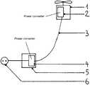
- FIG. 1represents a drone ( 1 ) provided with a power converter ( 2 ) connected by a wire ( 3 ) to a ground base ( 5 ) provided with a power converter ( 4 ) connected to the mains grid ( 6 ).
- FIG. 2allows comparing the voltages U B and U D as a function of the current I B for a conventional power supply device ( FIG. 2 a ) and a power supply device according to a particular embodiment of the invention ( FIG. 2 b ).
- the voltage U B in Voltis represented as a function of the current I B in Ampere
- the voltage U D in Voltas a function of the current I B in Ampere. It can be seen that the voltage U D available for the drone ( 1 ) drops with the power demanded for a conventional power supply device, whereas the voltage U D available for the drone ( 1 ) remains constant regardless of the power demanded for the power supply device according to a particular embodiment of the invention.
- FIG. 3illustrates the reaction of different power supply devices according to the invention when the power of the drone ( 1 ) increases suddenly.
- FIG. 3 arepresents the current I B in Ampere as a function of time in seconds. This current doubles suddenly at an instant called t.
- FIGS. 3 b , 3 c , 3 drepresent the reactions as a function of time of three different power supply devices according to the principle illustrated in FIG. 2 b .
- FIG. 3 bcorresponds to a device whose servo-control corresponds to a second-order system. It can be seen that the voltage U D varies strongly just after the instant t, which could lead to a major malfunction, either by overvoltage or under-voltage.
- FIG. 3 ccorresponds to a device whose servo-control corresponds to a first-order system. It can be seen that the voltage U D also varies strongly just after the instant t but there is no oscillation. The only possible malfunction is under-voltage.
- FIG. 3 dcorresponds to the same device as in FIG. 3 c but was added immediately upstream of the power converter ( 2 ) of the drone ( 1 ) a small capacity to cope with voltage variations and to smoothen U D .
- FIG. 4illustrates the reaction of different devices according to the invention when the power of the drone ( 1 ) decreases suddenly.
- FIG. 4 arepresents the current I B in Ampere as a function of time in seconds. This current is suddenly divided by 2 at an instant called t.
- FIGS. 4 b and 4 crepresent the reactions as a function of time of two different power supply devices according to the principle illustrated in FIG. 2 b .
- FIG. 4 bcorresponds to the same device as that of FIG. 3 c
- FIG. 4 ccorresponds to the same device as that of FIG. 3 d.
- FIG. 3 d or 4 cis optimal for the operation of the system.
- FIG. 5 arepresents, in dotted line, the power supply voltage U D which ensures a maximum efficiency of a power converter ( 2 ) located on the drone ( 1 ) as a function of the current I B which traverses the wire ( 3 ). It can be seen here that the optimal voltage U D varies considerably with the input current I B .
- FIG. 5 brepresents in full line the voltage U B delivered by a power supply device according to the invention which allows obtaining the optimal voltage U D to offer the drone ( 1 ) a maximum power as a function of the current I B .
- a drone ( 1 ) with a maximum power of 2600 W supplied with 25V direct voltageis used.
- This drone ( 1 )has a power converter ( 2 ) with a 1/16 fixed ratio connected to a wire or cable.
- This wire or cable100 m length, is constituted by two electric strands, an aramid strand, all in a plastic sheath. The resistance of the used electric strands is 0.06 ohm per meter.
- This wire or cable ( 3 )is connected to a power converter ( 4 ) in a ground base ( 5 ).
- the converter of the ground base ( 5 )is supplied by the mains grid ( 6 ) with 230V alternating voltage.
- the ground base ( 5 )includes a winding drum of the wire, a motor connected to the winding drum of the wire or cable ( 3 ) for winding or unwinding the wire or cable ( 3 ).
- a fancools the winding drum of the wire ( 3 ).
- a temperature sensoris present on the winding drum of the wire ( 3 ) to prevent the user from possible overheating of the wound wire ( 3 ).
- the drone ( 1 )has various on-board instruments and communicates in real-time with the ground base ( 5 ) through the technique called Power-Line Communication, well known to those skilled in the art. The information therefore passes via the power supply strands.
- the power converter ( 2 ) at the level of the drone ( 1 )has its maximum efficiency point at about 400V, requires not exceeding 410V at the input, otherwise it stops operating, and also requires never being supplied at more than 480V under penalty of irreparable damage.
- This power converter ( 2 )being with a 1/16 fixed ratio, it outputs a 25V voltage for an input voltage equal to 400V.
- the power converter ( 4 ) at the level of the ground base ( 5 )uses the so-called Power Factor Correction technique, well known to those skilled in the art.
- the modification of the power controllerrequires simple electronic components such as diodes, resistors, current sensors at the output of the converter, analog multipliers.
- the voltage U Dis equal to U B minus the ohmic losses in the wire ( 3 ) namely min (400+R B I B , 480) ⁇ R F I B Volts.
- the voltage U Dis almost constant and equal to 400V.
- the variation of the resistance R F of the power supply strands with temperatureis not taken into account.
- the power supply strands of this first embodimentare made of copper, and the resistivity of copper varies with temperature: the resistivity increases by about 50% between ⁇ 20 degrees Celsius and 70 degrees Celsius.
- the change of resistance R F of the wire ( 3 ) as a function of the temperaturetwo variations of the embodiment are possible.
- the first variation of the first embodiment according to the inventionconsists in using the information of the temperature sensor on the winding drum of the wire.
- the temperature measured by this sensoris called T F .
- a revolution counter on the winding drum of the wire ( 3 )allows knowing the length l of the wire ( 3 ) still wound on the drum.
- a temperature sensor on the ground base ( 5 )allows estimating the temperature T A of the ambient air.
- the second variation of the embodiment according to the inventionconsists in measuring regularly, every minute, U D the voltage at the input of the power converter ( 2 ) located on the drone ( 1 ), U B the voltage at the output of the power converter ( 4 ) of the ground base ( 5 ), and I B the current flowing in the wire.
- the measurement of U Dis sent to the ground base ( 5 ) via the power-line communication technique.
- the resistance R F of the power supply strands of the wire ( 3 )is then reevaluated by the Ohm law, by dividing the difference U B ⁇ U D by I B , and the regulation regulates according to the law min(400+R F I, 400).
- Another variation of the embodiment of the inventionconsists in carrying out a software-type rather than electronic voltage regulation of U B as previously described.
- a third variation of the embodiment according to the inventionconsists in regulating U B directly on the measured value of U D , this then requires a measurement of U D at high frequency, very significantly higher than one Herz, preferably in the range of a dozen kilohertz.
- the power supply system according to the inventionis capable of supplying power to all wired drones to the extent that it allows increasing the range and the payload compared to existing power supply systems.
Landscapes
- Engineering & Computer Science (AREA)
- Aviation & Aerospace Engineering (AREA)
- Chemical & Material Sciences (AREA)
- Combustion & Propulsion (AREA)
- Mechanical Engineering (AREA)
- Remote Sensing (AREA)
- Control Of Electrical Variables (AREA)
- Charge And Discharge Circuits For Batteries Or The Like (AREA)
- Electric Propulsion And Braking For Vehicles (AREA)
- Power Engineering (AREA)
Abstract
Description
- a device for plugging to an external source of electric energy, for example a ground battery, or the electric power grid,
- a power converter which converts the current-voltage couple of the external source to a current-voltage couple which flows in the wire,
- a wire as previously described,
- a power converter on the drone that allows converting the current-voltage couple flowing in the wire into the current-voltage couple usable by the drone.
This power converter is selected to be as light as possible, to increase the payload of the drone.
- the regulation compensates the voltage drop between the output of the power converter on the ground and the input of the power converter of the drone, due to the resistance RFof the wire,
- the regulation ensures a constant voltage UDat the input of the power converter on the drone, close to the optimal operating voltage of the power converter on the drone,
- the voltage UBdelivered by the power converter on the ground increases linearly with the current, according to an affine law of the type UB=U0+RBIBwhere U0designates a constant voltage, close to the optimal power supply voltage of the power converter of the drone, and RBdesignates a constant approximately equal to the resistance RFof the wire,
- the previous constant U0is replaced by a function U0(IB), such that this function is close to the function that describes the optimal power supply voltage of the power converter of the drone as a function of the power supply current,
- the variation of the resistance RFof the power supply strands of the wire with the temperature is taken into account, for example by measuring the temperature of the wire in one or several location(s), or measuring the ambient temperature, or both,
- the resistance RFof the wire is reevaluated regularly using the measurements of UB, UD, IBand Ohm's law,
- the regulation is based on a servo-control of the first-order servo-controls class or allowing not to obtain excessive oscillations of the voltage, even following a sudden variation of the power consumed by the drone,
- a circuit on the drone, interposed between the wire and the power converter of the drone, includes at least one capacitive-type element and absorbs the voltage variations during a sudden variation in the power consumed by the drone,
- the power converter at the level of the drone has a fixed ratio,
- UBis servo-controlled directly to the measurement of UD, the value of UDbeing transmitted via the wire.
- the regulation maximizes the ratio PM/TFor, which is equivalent, the ratio PM/IB, PMdesignating the power available for the motors of the drone, TFthe temperature of the wire, and IBthe current flowing in the wire.
Claims (19)
Applications Claiming Priority (3)
| Application Number | Priority Date | Filing Date | Title |
|---|---|---|---|
| FR1670361AFR3053259B1 (en) | 2016-07-01 | 2016-07-01 | POWER SUPPLY FOR WIRED DRONE |
| FR16/70361 | 2016-07-01 | ||
| PCT/IB2017/053683WO2018002775A1 (en) | 2016-07-01 | 2017-06-21 | Device for supplying power to a wired drone |
Publications (2)
| Publication Number | Publication Date |
|---|---|
| US20200091834A1 US20200091834A1 (en) | 2020-03-19 |
| US11059580B2true US11059580B2 (en) | 2021-07-13 |
Family
ID=57349062
Family Applications (1)
| Application Number | Title | Priority Date | Filing Date |
|---|---|---|---|
| US16/233,752ActiveUS11059580B2 (en) | 2016-07-01 | 2017-06-21 | Device for supplying power to a wired drone |
Country Status (5)
| Country | Link |
|---|---|
| US (1) | US11059580B2 (en) |
| EP (1) | EP3478386B1 (en) |
| CN (1) | CN109414624A (en) |
| FR (1) | FR3053259B1 (en) |
| WO (1) | WO2018002775A1 (en) |
Families Citing this family (6)
| Publication number | Priority date | Publication date | Assignee | Title |
|---|---|---|---|---|
| FR3066923B1 (en)* | 2017-05-31 | 2021-01-01 | Elistair | PROTECTIVE DEVICE FOR THE CONNECTION BETWEEN A DETACHABLE WIRED DRONE AND ITS WIRE. |
| IT201800010924A1 (en) | 2018-12-10 | 2020-06-10 | E Novia S P A | System and method for controlling overhead cables in remotely piloted aircraft systems |
| IL266249B (en) | 2019-04-18 | 2020-08-31 | Pearlsof Wisdom Advanced Tech Ltd | A system and method for drone release detection |
| US11460866B2 (en) | 2019-04-18 | 2022-10-04 | Pearls Of Wisdom Advanced Technologies Ltd | UAV carrier |
| IT201900009522A1 (en) | 2019-06-19 | 2020-12-19 | E Novia S P A | Drone and its attitude control method |
| IT201900009534A1 (en) | 2019-06-19 | 2020-12-19 | E Novia S P A | Drone and its attitude control method |
Citations (24)
| Publication number | Priority date | Publication date | Assignee | Title |
|---|---|---|---|---|
| US4606074A (en) | 1984-06-14 | 1986-08-12 | Winegard Company | Automatic voltage line loss compensation control for an antenna receiver |
| US6325330B1 (en) | 1998-08-18 | 2001-12-04 | Lockheed Martin Corporation | Power generation, transmission, and distribution system for an aerostat using a lightweight tether |
| US20070200027A1 (en)* | 2006-02-24 | 2007-08-30 | Johnson Samuel A | Aerial robot |
| US20090134709A1 (en)* | 2007-11-26 | 2009-05-28 | Liming Sun | System and method for cable resistance cancellation |
| US20100181840A1 (en)* | 2009-01-16 | 2010-07-22 | Cambridge Semiconductor Limited | Cable compensation |
| CN101847929A (en) | 2009-03-23 | 2010-09-29 | 尼克森微电子股份有限公司 | Power supply control circuit with line loss compensation function |
| US20100295303A1 (en) | 2009-05-21 | 2010-11-25 | Makani Power, Inc. | Tethered system for power generation |
| US20110037445A1 (en)* | 2009-08-13 | 2011-02-17 | Niko Semiconductor Co., Ltd. | Power control circuit for wire compensation and compensation method of the same |
| US20120062195A1 (en)* | 2010-09-15 | 2012-03-15 | Analog Vision Technology Inc. | Active wire compensation circuit and controller with the same |
| WO2013013219A1 (en) | 2011-07-20 | 2013-01-24 | L-3 Communications Corporation | Tethered payload system and method |
| US8444081B2 (en)* | 2007-07-17 | 2013-05-21 | Jst, Llc | High voltage flying apparatus employing multiple motors |
| CN103144779A (en) | 2012-11-30 | 2013-06-12 | 中国电子科技集团公司第七研究所 | Multi-rotor-wing unmanned aerial vehicle mooring system |
| US8695919B2 (en)* | 2010-11-12 | 2014-04-15 | Sky Sapience Ltd. | Aerial unit and method for elevating payloads |
| US20140167682A1 (en)* | 2012-09-14 | 2014-06-19 | Astronics Advanced Electronics Systems Corp. | USB Power Supply |
| US20140177303A1 (en)* | 2012-12-21 | 2014-06-26 | Texas Instruments Incorporated | Volt-second integration cable compensation circuit |
| US20150354539A1 (en) | 2013-12-31 | 2015-12-10 | Google Inc. | High Frequency Bi-directional AC Power Transmission |
| CN105270637A (en)* | 2014-07-10 | 2016-01-27 | 王欢 | Electric aircraft with voltage conversion device |
| CN205060039U (en) | 2015-09-18 | 2016-03-02 | 邱玉燕 | External power source power supply power line communication remote control flight ware system |
| WO2016059953A1 (en) | 2014-10-17 | 2016-04-21 | ソニー株式会社 | Electric power supply system |
| US20160254752A1 (en)* | 2015-02-26 | 2016-09-01 | Dell Products, Lp | System and Method for Compensating for Cable Voltage Loss at Various Output Voltages |
| LT6316B (en)* | 2014-12-31 | 2016-09-12 | My Research, Uab | A remote power source for unmanned aerial vehicle |
| US20160357204A1 (en)* | 2015-06-08 | 2016-12-08 | Acer Incorporated | Power supply apparatus with cable voltage drop compensation |
| CN106233752A (en) | 2014-04-30 | 2016-12-14 | 三星电子株式会社 | speaker device |
| US20170003326A1 (en)* | 2015-06-30 | 2017-01-05 | Hanchett Entry Systems, Inc. | Device for measuring voltage across a remote load |
Family Cites Families (1)
| Publication number | Priority date | Publication date | Assignee | Title |
|---|---|---|---|---|
| CN105564655A (en)* | 2014-10-11 | 2016-05-11 | 王欢 | Electric aircraft |
- 2016
- 2016-07-01FRFR1670361Apatent/FR3053259B1/ennot_activeExpired - Fee Related
- 2017
- 2017-06-21EPEP17743079.0Apatent/EP3478386B1/enactiveActive
- 2017-06-21CNCN201780039725.3Apatent/CN109414624A/enactivePending
- 2017-06-21WOPCT/IB2017/053683patent/WO2018002775A1/ennot_activeCeased
- 2017-06-21USUS16/233,752patent/US11059580B2/enactiveActive
Patent Citations (24)
| Publication number | Priority date | Publication date | Assignee | Title |
|---|---|---|---|---|
| US4606074A (en) | 1984-06-14 | 1986-08-12 | Winegard Company | Automatic voltage line loss compensation control for an antenna receiver |
| US6325330B1 (en) | 1998-08-18 | 2001-12-04 | Lockheed Martin Corporation | Power generation, transmission, and distribution system for an aerostat using a lightweight tether |
| US20070200027A1 (en)* | 2006-02-24 | 2007-08-30 | Johnson Samuel A | Aerial robot |
| US8444081B2 (en)* | 2007-07-17 | 2013-05-21 | Jst, Llc | High voltage flying apparatus employing multiple motors |
| US20090134709A1 (en)* | 2007-11-26 | 2009-05-28 | Liming Sun | System and method for cable resistance cancellation |
| US20100181840A1 (en)* | 2009-01-16 | 2010-07-22 | Cambridge Semiconductor Limited | Cable compensation |
| CN101847929A (en) | 2009-03-23 | 2010-09-29 | 尼克森微电子股份有限公司 | Power supply control circuit with line loss compensation function |
| US20100295303A1 (en) | 2009-05-21 | 2010-11-25 | Makani Power, Inc. | Tethered system for power generation |
| US20110037445A1 (en)* | 2009-08-13 | 2011-02-17 | Niko Semiconductor Co., Ltd. | Power control circuit for wire compensation and compensation method of the same |
| US20120062195A1 (en)* | 2010-09-15 | 2012-03-15 | Analog Vision Technology Inc. | Active wire compensation circuit and controller with the same |
| US8695919B2 (en)* | 2010-11-12 | 2014-04-15 | Sky Sapience Ltd. | Aerial unit and method for elevating payloads |
| WO2013013219A1 (en) | 2011-07-20 | 2013-01-24 | L-3 Communications Corporation | Tethered payload system and method |
| US20140167682A1 (en)* | 2012-09-14 | 2014-06-19 | Astronics Advanced Electronics Systems Corp. | USB Power Supply |
| CN103144779A (en) | 2012-11-30 | 2013-06-12 | 中国电子科技集团公司第七研究所 | Multi-rotor-wing unmanned aerial vehicle mooring system |
| US20140177303A1 (en)* | 2012-12-21 | 2014-06-26 | Texas Instruments Incorporated | Volt-second integration cable compensation circuit |
| US20150354539A1 (en) | 2013-12-31 | 2015-12-10 | Google Inc. | High Frequency Bi-directional AC Power Transmission |
| CN106233752A (en) | 2014-04-30 | 2016-12-14 | 三星电子株式会社 | speaker device |
| CN105270637A (en)* | 2014-07-10 | 2016-01-27 | 王欢 | Electric aircraft with voltage conversion device |
| WO2016059953A1 (en) | 2014-10-17 | 2016-04-21 | ソニー株式会社 | Electric power supply system |
| LT6316B (en)* | 2014-12-31 | 2016-09-12 | My Research, Uab | A remote power source for unmanned aerial vehicle |
| US20160254752A1 (en)* | 2015-02-26 | 2016-09-01 | Dell Products, Lp | System and Method for Compensating for Cable Voltage Loss at Various Output Voltages |
| US20160357204A1 (en)* | 2015-06-08 | 2016-12-08 | Acer Incorporated | Power supply apparatus with cable voltage drop compensation |
| US20170003326A1 (en)* | 2015-06-30 | 2017-01-05 | Hanchett Entry Systems, Inc. | Device for measuring voltage across a remote load |
| CN205060039U (en) | 2015-09-18 | 2016-03-02 | 邱玉燕 | External power source power supply power line communication remote control flight ware system |
Non-Patent Citations (8)
| Title |
|---|
| "Voltage regulation," article from Wikipedia, edited Mar. 20, 2020. Retrieved from https://en.wikipedia.org/w/index.php?title=Voltage_regulation&oldid=946532018 on Jul. 6, 2020. (Year: 2020).* |
| English abstract of LT2014152A, originally published Jul. 11, 2016 (original document unavailable). Translation obtained from Espacenet, https://worldwide.espacenet.com/ on Jan. 18, 2020. (Year: 2016).* |
| English Translation for First Office Action for Application No. 201730039725.3. |
| First Office Action for Application No. 201780039725.3. |
| First Search for Application No. 201780039725.3. |
| Machine translation of LT6316B, Sep. 12, 2016. Obtained from Espacenet, https://worldwide.espacenet.com/ on Jan. 18, 2020. (Year: 2016).* |
| Search Report for PCT/IB2017/053683. |
| Written Opinion for PCT/IB2017/053683. |
Also Published As
| Publication number | Publication date |
|---|---|
| EP3478386B1 (en) | 2020-07-22 |
| FR3053259A1 (en) | 2018-01-05 |
| WO2018002775A1 (en) | 2018-01-04 |
| FR3053259B1 (en) | 2020-10-23 |
| CN109414624A (en) | 2019-03-01 |
| US20200091834A1 (en) | 2020-03-19 |
| EP3478386A1 (en) | 2019-05-08 |
Similar Documents
| Publication | Publication Date | Title |
|---|---|---|
| US11059580B2 (en) | Device for supplying power to a wired drone | |
| US7598713B2 (en) | System and method for electric current and power monitor and control of a generator | |
| WO2005034326A1 (en) | Power converter | |
| JP2015031582A (en) | Current measuring device | |
| US20160214488A1 (en) | Wireless power supply system and power transmission device | |
| US9866051B2 (en) | Adaptive charger to maximize charge rate | |
| US20150115874A1 (en) | Method and system for controlling charging of an energy storage device | |
| EP3417526A1 (en) | Systems and methods for simultaneously charging a battery with multiple power sources | |
| CN106575869B (en) | HVDC electric power system for aircraft | |
| CN201839251U (en) | Electric control circuit structure of TFKX-H series controllable marine phase compound excitation generator | |
| CN105745834B (en) | For the proportional integration regulating loop of the digital governer device of motor vehicles excitation electric rotating machine | |
| KR101845432B1 (en) | High efficiency generator with permanent excitation | |
| US20110136451A1 (en) | Telecommunication device having a loop-supplied device and method for the operating voltage supply thereof | |
| JP5026179B2 (en) | Cable fault point measuring instrument | |
| US20170310117A1 (en) | Systems And Methods For Closed Loop Control For Wireless Power Transfer | |
| JP2008061420A (en) | Power supply device and power supply system | |
| CN105700607A (en) | Supply voltage regulating circuit and electronic device | |
| JP5888688B1 (en) | Two-wire signal receiver and method of using surplus voltage of two-wire signal receiver | |
| JP6347364B2 (en) | Power supply system, DC power supply device, and test method using the same | |
| CN109314469B (en) | switching power supply | |
| CN113258534B (en) | Power converter and protection circuit thereof | |
| CN104242295A (en) | Sample cooling device for histological samples | |
| KR100766655B1 (en) | Power converter | |
| EP3620252A1 (en) | Resistance soldering system and method | |
| CN104124003A (en) | Wire and cable take-up control system |
Legal Events
| Date | Code | Title | Description |
|---|---|---|---|
| FEPP | Fee payment procedure | Free format text:ENTITY STATUS SET TO UNDISCOUNTED (ORIGINAL EVENT CODE: BIG.); ENTITY STATUS OF PATENT OWNER: SMALL ENTITY | |
| AS | Assignment | Owner name:ELISTAIR, FRANCE Free format text:ASSIGNMENT OF ASSIGNORS INTEREST;ASSIGNORS:CALVEZ, CYRIL FRANK;PENET, MARIE MARC HERVE TIMOTHEE;DE MARLIAVE, CHRISTIAN MARIE GUILHEM;AND OTHERS;REEL/FRAME:048001/0300 Effective date:20190110 | |
| FEPP | Fee payment procedure | Free format text:ENTITY STATUS SET TO SMALL (ORIGINAL EVENT CODE: SMAL); ENTITY STATUS OF PATENT OWNER: SMALL ENTITY | |
| AS | Assignment | Owner name:ELISTAIR, FRANCE Free format text:CORRECTIVE ASSIGNMENT TO CORRECT THE 4TH INVENTOR'S NAME PREVIOUSLY RECORDED AT REEL: 48001 FRAME: 300. ASSIGNOR(S) HEREBY CONFIRMS THE ASSINGMENT;ASSIGNORS:CALVEZ, CYRIL FRANK;PENET, MARIE MARC HERVE TIMOTHEE;DE MARLIAVE, CHRISTIAN MARIE GUILHEM;AND OTHERS;REEL/FRAME:051581/0090 Effective date:20191001 | |
| STPP | Information on status: patent application and granting procedure in general | Free format text:NOTICE OF ALLOWANCE MAILED -- APPLICATION RECEIVED IN OFFICE OF PUBLICATIONS | |
| STPP | Information on status: patent application and granting procedure in general | Free format text:DOCKETED NEW CASE - READY FOR EXAMINATION | |
| STPP | Information on status: patent application and granting procedure in general | Free format text:NOTICE OF ALLOWANCE MAILED -- APPLICATION RECEIVED IN OFFICE OF PUBLICATIONS | |
| STPP | Information on status: patent application and granting procedure in general | Free format text:PUBLICATIONS -- ISSUE FEE PAYMENT RECEIVED | |
| STPP | Information on status: patent application and granting procedure in general | Free format text:PUBLICATIONS -- ISSUE FEE PAYMENT VERIFIED | |
| STCF | Information on status: patent grant | Free format text:PATENTED CASE | |
| FEPP | Fee payment procedure | Free format text:MAINTENANCE FEE REMINDER MAILED (ORIGINAL EVENT CODE: REM.); ENTITY STATUS OF PATENT OWNER: SMALL ENTITY | |
| FEPP | Fee payment procedure | Free format text:SURCHARGE FOR LATE PAYMENT, SMALL ENTITY (ORIGINAL EVENT CODE: M2554); ENTITY STATUS OF PATENT OWNER: SMALL ENTITY | |
| MAFP | Maintenance fee payment | Free format text:PAYMENT OF MAINTENANCE FEE, 4TH YR, SMALL ENTITY (ORIGINAL EVENT CODE: M2551); ENTITY STATUS OF PATENT OWNER: SMALL ENTITY Year of fee payment:4 |