US11059088B2 - Systems and methods for processing alloy ingots - Google Patents
Systems and methods for processing alloy ingotsDownload PDFInfo
- Publication number
- US11059088B2 US11059088B2US15/048,210US201615048210AUS11059088B2US 11059088 B2US11059088 B2US 11059088B2US 201615048210 AUS201615048210 AUS 201615048210AUS 11059088 B2US11059088 B2US 11059088B2
- Authority
- US
- United States
- Prior art keywords
- ingot
- metallic material
- alloy
- circumferential surface
- cylindrical
- Prior art date
- Legal status (The legal status is an assumption and is not a legal conclusion. Google has not performed a legal analysis and makes no representation as to the accuracy of the status listed.)
- Active, expires
Links
Images


Classifications
- B—PERFORMING OPERATIONS; TRANSPORTING
- B23—MACHINE TOOLS; METAL-WORKING NOT OTHERWISE PROVIDED FOR
- B23K—SOLDERING OR UNSOLDERING; WELDING; CLADDING OR PLATING BY SOLDERING OR WELDING; CUTTING BY APPLYING HEAT LOCALLY, e.g. FLAME CUTTING; WORKING BY LASER BEAM
- B23K9/00—Arc welding or cutting
- B23K9/04—Welding for other purposes than joining, e.g. built-up welding
- B23K9/044—Built-up welding on three-dimensional surfaces
- B23K9/046—Built-up welding on three-dimensional surfaces on surfaces of revolution
- B23K9/048—Built-up welding on three-dimensional surfaces on surfaces of revolution on cylindrical surfaces
- B—PERFORMING OPERATIONS; TRANSPORTING
- B21—MECHANICAL METAL-WORKING WITHOUT ESSENTIALLY REMOVING MATERIAL; PUNCHING METAL
- B21D—WORKING OR PROCESSING OF SHEET METAL OR METAL TUBES, RODS OR PROFILES WITHOUT ESSENTIALLY REMOVING MATERIAL; PUNCHING METAL
- B21D31/00—Other methods for working sheet metal, metal tubes, metal profiles
- B—PERFORMING OPERATIONS; TRANSPORTING
- B22—CASTING; POWDER METALLURGY
- B22D—CASTING OF METALS; CASTING OF OTHER SUBSTANCES BY THE SAME PROCESSES OR DEVICES
- B22D25/00—Special casting characterised by the nature of the product
- B22D25/02—Special casting characterised by the nature of the product by its peculiarity of shape; of works of art
- B—PERFORMING OPERATIONS; TRANSPORTING
- B22—CASTING; POWDER METALLURGY
- B22D—CASTING OF METALS; CASTING OF OTHER SUBSTANCES BY THE SAME PROCESSES OR DEVICES
- B22D7/00—Casting ingots, e.g. from ferrous metals
- B—PERFORMING OPERATIONS; TRANSPORTING
- B23—MACHINE TOOLS; METAL-WORKING NOT OTHERWISE PROVIDED FOR
- B23K—SOLDERING OR UNSOLDERING; WELDING; CLADDING OR PLATING BY SOLDERING OR WELDING; CUTTING BY APPLYING HEAT LOCALLY, e.g. FLAME CUTTING; WORKING BY LASER BEAM
- B23K35/00—Rods, electrodes, materials, or media, for use in soldering, welding, or cutting
- B23K35/22—Rods, electrodes, materials, or media, for use in soldering, welding, or cutting characterised by the composition or nature of the material
- B23K35/24—Selection of soldering or welding materials proper
- B23K35/30—Selection of soldering or welding materials proper with the principal constituent melting at less than 1550 degrees C
- B23K35/3033—Ni as the principal constituent
- C—CHEMISTRY; METALLURGY
- C21—METALLURGY OF IRON
- C21D—MODIFYING THE PHYSICAL STRUCTURE OF FERROUS METALS; GENERAL DEVICES FOR HEAT TREATMENT OF FERROUS OR NON-FERROUS METALS OR ALLOYS; MAKING METAL MALLEABLE, e.g. BY DECARBURISATION OR TEMPERING
- C21D7/00—Modifying the physical properties of iron or steel by deformation
- C21D7/13—Modifying the physical properties of iron or steel by deformation by hot working
- C—CHEMISTRY; METALLURGY
- C22—METALLURGY; FERROUS OR NON-FERROUS ALLOYS; TREATMENT OF ALLOYS OR NON-FERROUS METALS
- C22B—PRODUCTION AND REFINING OF METALS; PRETREATMENT OF RAW MATERIALS
- C22B9/00—General processes of refining or remelting of metals; Apparatus for electroslag or arc remelting of metals
- C22B9/003—General processes of refining or remelting of metals; Apparatus for electroslag or arc remelting of metals by induction
- C—CHEMISTRY; METALLURGY
- C22—METALLURGY; FERROUS OR NON-FERROUS ALLOYS; TREATMENT OF ALLOYS OR NON-FERROUS METALS
- C22B—PRODUCTION AND REFINING OF METALS; PRETREATMENT OF RAW MATERIALS
- C22B9/00—General processes of refining or remelting of metals; Apparatus for electroslag or arc remelting of metals
- C22B9/04—Refining by applying a vacuum
- C—CHEMISTRY; METALLURGY
- C22—METALLURGY; FERROUS OR NON-FERROUS ALLOYS; TREATMENT OF ALLOYS OR NON-FERROUS METALS
- C22B—PRODUCTION AND REFINING OF METALS; PRETREATMENT OF RAW MATERIALS
- C22B9/00—General processes of refining or remelting of metals; Apparatus for electroslag or arc remelting of metals
- C22B9/16—Remelting metals
- C22B9/18—Electroslag remelting
- C—CHEMISTRY; METALLURGY
- C22—METALLURGY; FERROUS OR NON-FERROUS ALLOYS; TREATMENT OF ALLOYS OR NON-FERROUS METALS
- C22B—PRODUCTION AND REFINING OF METALS; PRETREATMENT OF RAW MATERIALS
- C22B9/00—General processes of refining or remelting of metals; Apparatus for electroslag or arc remelting of metals
- C22B9/16—Remelting metals
- C22B9/20—Arc remelting
- C—CHEMISTRY; METALLURGY
- C22—METALLURGY; FERROUS OR NON-FERROUS ALLOYS; TREATMENT OF ALLOYS OR NON-FERROUS METALS
- C22F—CHANGING THE PHYSICAL STRUCTURE OF NON-FERROUS METALS AND NON-FERROUS ALLOYS
- C22F1/00—Changing the physical structure of non-ferrous metals or alloys by heat treatment or by hot or cold working
- C22F1/10—Changing the physical structure of non-ferrous metals or alloys by heat treatment or by hot or cold working of nickel or cobalt or alloys based thereon
- Y—GENERAL TAGGING OF NEW TECHNOLOGICAL DEVELOPMENTS; GENERAL TAGGING OF CROSS-SECTIONAL TECHNOLOGIES SPANNING OVER SEVERAL SECTIONS OF THE IPC; TECHNICAL SUBJECTS COVERED BY FORMER USPC CROSS-REFERENCE ART COLLECTIONS [XRACs] AND DIGESTS
- Y02—TECHNOLOGIES OR APPLICATIONS FOR MITIGATION OR ADAPTATION AGAINST CLIMATE CHANGE
- Y02P—CLIMATE CHANGE MITIGATION TECHNOLOGIES IN THE PRODUCTION OR PROCESSING OF GOODS
- Y02P10/00—Technologies related to metal processing
- Y02P10/25—Process efficiency
- Y—GENERAL TAGGING OF NEW TECHNOLOGICAL DEVELOPMENTS; GENERAL TAGGING OF CROSS-SECTIONAL TECHNOLOGIES SPANNING OVER SEVERAL SECTIONS OF THE IPC; TECHNICAL SUBJECTS COVERED BY FORMER USPC CROSS-REFERENCE ART COLLECTIONS [XRACs] AND DIGESTS
- Y10—TECHNICAL SUBJECTS COVERED BY FORMER USPC
- Y10T—TECHNICAL SUBJECTS COVERED BY FORMER US CLASSIFICATION
- Y10T428/00—Stock material or miscellaneous articles
- Y10T428/12—All metal or with adjacent metals
- Y10T428/12493—Composite; i.e., plural, adjacent, spatially distinct metal components [e.g., layers, joint, etc.]
Definitions
- the present disclosureis directed to systems and methods for processing alloy ingots.
- the present disclosureis also directed to processes for hot working alloy ingots.
- Metal alloy productsmay be prepared, for example, using ingot metallurgy operations or powder metallurgy operations.
- Ingot metallurgy operationsmay involve the melting of an alloy feedstock and the casting of the molten material into an ingot.
- a non-limiting example of an ingot metallurgy operationis a “triple melt” technique, which includes three melting operations: (1) vacuum induction melting (VIM) to prepare a desired alloy composition from a feedstock; (2) electroslag refining (ESR), which may reduce levels of, for example, oxygen-containing inclusions; and (3) vacuum arc remelting (VAR), which may reduce compositional segregation that may occur during solidification after ESR.
- An ingotmay be formed during solidification after a VAR operation.
- Powder metallurgy operationsmay involve atomization of molten alloy and the collection and consolidation of solidified metallurgical powders into an ingot.
- a non-limiting example of a powder metallurgy operationincludes the steps of: (1) VIM to prepare a desired alloy composition from a feedstock; (2) atomization of molten alloy into molten alloy droplets that solidify into alloy powder; (3) optionally, sieving to reduce inclusions; (4) canning and degassing; and (5) pressing to consolidate the alloy powder into an alloy ingot.
- the alloy ingots formed from ingot metallurgy operations and powder metallurgy operationsmay be hot worked to produce other alloy products.
- the ingotmay undergo forging and/or extrusion to form a billet or other alloy article from the ingot.
- Embodiments disclosed hereinare directed to an ingot processing method.
- An ingot processing methodmay comprise depositing a metallic material layer onto at least a region of a surface of an alloy ingot.
- the ingot processing methodmay be characterized in that the metallic material layer reduces an incidence of surface cracking of the alloy ingot during hot working.
- the hot working processmay comprise applying force to an alloy ingot to deform the alloy ingot.
- the alloy ingotmay include a metallic material layer deposited onto at least a region of a surface of the alloy ingot.
- the hot working processmay be characterized in that the force is applied onto the metallic material layer.
- An ingot processing systemmay comprise an ingot positioning apparatus.
- the ingot positioning apparatusmay be configured to rotate an ingot about a long axis of the ingot.
- the ingot processing systemmay also comprise a welding apparatus.
- the welding apparatusmay be configured to deposit a metallic material layer as a weld deposit onto at least a region of a surface of an ingot.
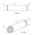
- FIG. 1Ais a side view of an ingot having a metallic material layer deposited onto the end surfaces of the ingot
- FIG. 1Bis a perspective view of the ingot shown in FIG. 1A ;
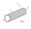
- FIG. 2is a perspective view of an ingot having a metallic material layer deposited onto a circumferential surface of the ingot;
- FIG. 3Ais a side view of an ingot having a metallic material layer deposited onto the end surfaces and a circumferential surface of the ingot
- FIG. 3Bis a perspective view of the ingot shown in FIG. 3A ;
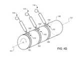
- FIGS. 4A-4Dare perspective views illustrating one method of depositing metallic material as weld deposits onto a circumferential surface of an ingot
- FIGS. 5A-5Dare perspective views illustrating another method of depositing metallic material as weld deposits onto a circumferential surface of an ingot
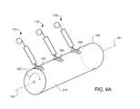
- FIG. 6Ais a perspective view illustrating another embodiment of a method of depositing metallic material as a weld deposit onto a circumferential surface of an ingot
- FIG. 6Bis a perspective view of the ingot shown in FIG. 6A and having a metallic material layer deposited as a weld deposit over the entire circumferential surface of the ingot;
- FIG. 7Ais a side cross-sectional view of an ingot in an upset forging operation
- FIG. 7Bis an expanded partial side cross-sectional view of the ingot shown in FIG. 7A after upset forging
- FIG. 7Cis a side cross-sectional view of an ingot in an upset forging operation and having a metallic material layer deposited onto the end surfaces of the ingot
- FIG. 7Dis an expanded partial side cross-sectional view of the ingot shown in FIG. 7C after upset forging;
- FIG. 8Ais a side cross-sectional view of an ingot in a draw forging operation
- FIG. 8Bis an expanded partial side cross-sectional view of the ingot shown in FIG. 8A after draw forging
- FIG. 8Cis a side cross-sectional view of an ingot in a draw forging operation and having a metallic material layer deposited onto the circumferential surface of the ingot
- FIG. 8Dis an expanded partial side cross-sectional view of the ingot shown in FIG. 8C after draw forging;
- FIG. 9Ais a photograph of two 3-inch alloy cubes, each having a metallic material layer deposited by a welding operation on the top surface of the cube (as oriented in the photograph);
- FIG. 9Bis a schematic diagram of the photograph shown in FIG. 9A ;
- FIGS. 10A and 10Bare photographs of the two die-contacting surfaces of a 1-inch pancake that was press forged from a 3-inch alloy cube having a metallic material layer deposited by a welding operation onto one die-contacting surface of the alloy cube;
- FIGS. 10C and 10Dare schematic diagrams of the photographs respectively shown in FIGS. 10A and 10B ;
- FIG. 11Ais a photograph of a sectioned 1-inch pancake that was press forged from a 3-inch alloy cube having a metallic material layer deposited by a welding operation onto one die-contacting surface of the alloy cube (the top surface as oriented in the photograph);
- FIG. 11Bis a micrograph taken along the cross-section of the welded surface as indicated in FIG. 11A
- FIGS. 11C and 11Dare schematic diagrams of the photographs respectively shown in FIGS. 11A and 11B .
- any numerical range recited hereinis intended to include all sub-ranges subsumed therein.
- a range of “1 to 10”is intended to include all sub-ranges between (and including) the recited minimum value of 1 and the recited maximum value of 10, that is, having a minimum value equal to or greater than 1 and a maximum value of equal to or less than 10.
- Any maximum numerical limitation recited hereinis intended to include all lower numerical limitations subsumed therein and any minimum numerical limitation recited herein is intended to include all higher numerical limitations subsumed therein. Accordingly, Applicants reserve the right to amend the present disclosure, including the claims, to expressly recite any sub-range subsumed within the ranges expressly recited herein.
- grammatical articles “one”, “a”, “an”, and “the”, as used herein,are intended to include “at least one” or “one or more”, unless otherwise indicated.
- the articlesare used herein to refer to one or more than one (i.e., to at least one) of the grammatical objects of the article.
- a componentmeans one or more components, and thus, possibly, more than one component is contemplated and may be employed or used in an implementation of the described embodiments.
- the various embodiments disclosed and described hereincan comprise, consist of, or consist essentially of, the features, aspects, characteristics, and the like, as variously described herein.
- the various embodiments disclosed and described hereincan also comprise additional or optional features, aspects, characteristics, and the like, that are known in the art or that may otherwise be included in various embodiments as implemented in practice.
- crack sensitive alloystend to form cracks during working operations.
- Crack sensitive alloy ingotsmay form cracks during hot working operations used to produce alloy articles from the crack sensitive alloy ingots.
- alloy billetsmay be formed from alloy ingots using forge conversion.
- Other alloy articlesmay be formed from alloy billets or alloy ingots using extrusion or other working operations.
- the production yield of alloy articles (e.g., alloy billets) formed from crack sensitive alloy ingots using hot working operationsmay be low because of the incidence of surface cracking of the alloy ingots during the hot working (e.g., during forging or extrusion).
- hot workingrefers to the application of force to a workpiece at a temperature greater than ambient temperature, wherein the applied force deforms the workpiece.
- the temperature of an alloy ingot undergoing the working operationmay be greater than the temperature of the dies used to mechanically apply force to the surfaces of the ingot.
- the resulting thermal gradient off-set between the ingot surfaces and the contacting diesmay contribute to surface cracking of the ingot during hot working, particularly for ingots formed from crack sensitive alloys, such as, for example, nickel base, iron base, nickel-iron base, and cobalt base alloys and superalloys.
- Embodiments disclosed hereinare directed to ingot processing methods and hot working processes characterized by a reduction in the incidence of surface cracking of an alloy ingot during a hot working operation.
- the described methods and/or processesmay comprise depositing a metallic material layer onto at least a region of a surface of an alloy ingot.
- the alloy, ingotmay be hot worked by applying a force to the alloy ingot at the region of the surface having the deposited metallic material layer. The applied force may deform the alloy ingot.
- the alloy ingotmay comprise a crack sensitive alloy.
- various nickel base, iron base, nickel-iron base, and cobalt base alloys and superalloysmay be crack sensitive, especially during hot working operations.
- An alloy ingotmay be formed from such crack sensitive alloys and superalloys.
- a crack sensitive alloy ingotmay be formed from alloys or superalloys including, but not limited to, Alloy 718, Alloy 720, Rene 41TM alloy, Rene 88TM alloy, Waspaloy® alloy, and Inconel® 100.
- the methods, processes, and systems described hereinare generally applicable to any alloy characterized by a relatively low ductility at hot working temperatures.
- alloyincludes conventional alloys and superalloys, wherein superalloys exhibit relatively good surface stability, corrosion and oxidation resistance, high strength, and high creep resistance at high temperatures.
- An alloy ingotmay be formed using an ingot metallurgy operation or a powder metallurgy operation.
- an alloy ingotmay be formed by VIM followed by VAR (a VIM-VAR operation).
- an alloy ingotmay be formed by triple melting in which an ESR operation is performed intermediate a VIM operation and a VAR operation (a VIM-ESR-VAR operation).
- an alloy ingotmay be formed using a powder metallurgy operation involving atomization of molten alloy and the collection and consolidation of resulting metallurgical powders into an ingot.
- an alloy ingotmay be formed using a spray forming operation.
- VIMmay be used to prepare a base alloy composition from a feedstock.
- An ESR operationmay optionally be used after VIM.
- Molten alloymay be extracted from a VIM or ESR melt pool and atomized to form molten droplets.
- the molten alloymay be extracted from a melt pool using a cold wall induction guide (CIG), for example.
- CCGcold wall induction guide
- the molten alloy dropletsmay be deposited using a spray forming operation to form a solidified ingot.
- an alloy ingotmay be heat treated and/or surface conditioned.
- an alloy ingotmay be exposed to high temperatures to homogenize the alloy composition and microstructure of the ingot.
- the high temperaturesmay be above the recrystallization temperature of the alloy but below the melting point temperature of the alloy.
- An alloy ingotmay be surface conditioned, for example, by grinding or peeling the surface of the ingot.
- An alloy ingotmay also be sanded and/or buffed.
- Surface conditioning operationsmay be performed before and/or after any optional heat treatment steps, such as, for example, homogenization at high temperatures.
- a metallic material layermay be deposited and metallurgically bonded to at least a region of a surface of an alloy ingot.
- a metallic material layermay be deposited as a weld deposit onto a surface of an ingot.
- a weld depositmay be metallurgically bonded to at least a region of a surface of an alloy ingot using welding operations including, but not limited to, metal inert gas (MIG) welding, tungsten insert gas (TIG) welding, plasma welding, submerged arc welding, and electron-beam welding.
- MIGmetal inert gas
- TOGtungsten insert gas
- the metallic material layermay comprise a metallic material that is more ductile and/or malleable than the alloy of the underlying ingot at the particular working temperature to be used.
- the metallic material layermay comprise a metallic material that exhibits greater toughness and/or lesser hardness than the alloy of the underlying ingot at the particular working temperature to be used.
- the metallic material layerinsulates the underlying ingot surface from the surfaces of contacting dies, thereby preventing the underlying ingot surface from cooling to a brittle temperature at which the surface may more readily crack during hot working.
- the metallic material layermay comprise a metallic material that is oxidation resistant. In various embodiments, the metallic material layer does not oxidize during hot working or otherwise.
- the metallic material layermay comprise a metallic material exhibiting a relatively high stiffness (e.g., a relatively low elastic modulus). In various embodiments, the metallic material layer does not thin out substantially during hot working (e.g., where the application of force by one or more dies would cause a relatively low stiffness metallic material to thin out on the underlying ingot surface).
- the metallic material and the alloy forming the underlying ingotmay comprise the same base metal.
- the alloy ingotcomprises a nickel base alloy or superalloy (e.g., Alloy 720, Rene 88TM alloy, or Waspaloy® alloy)
- the metallic material of the deposited layermay also comprise a nickel base alloy, such as, for example, a nickel base weld alloy (e.g., Techalloy 606TM alloy (available from Techalloy Company/Central Wire)).
- the metallic material layermay be deposited to a thickness sufficient to insulate the underlying ingot surface from the surfaces of contacting dies, thereby preventing the underlying ingot surface from cooling to a temperature at which the underlying surface may more readily crack during hot working. In this manner, greater hot working temperatures may generally correlate with greater metallic material layer thicknesses. In various embodiments, the metallic material layer may be deposited to a thickness of 0.25 inches to 0.5 inches onto at least a region of a surface of an alloy ingot.
- the temperature range over which alloys can be effectively hot workedis based on the temperature at which cracks initiate in the alloy. At a given starting temperature for a hot working operation, some alloys can be effectively hot worked over a larger temperature range than other alloys because of differences in the temperature at which cracks initiate in the alloy. For alloys having a relatively small hot working temperature range (i.e., the difference between the starting temperature and the temperature at which cracks initiate), the thickness of the metallic material layer may need to be relatively greater to prevent the underlying ingot from cooling down to a brittle temperature range in which cracks initiate. Likewise, for alloys having a relatively large hot working temperature range, the thickness of the metallic material layer may be relatively smaller to and still prevent the underlying ingot from cooling down to a brittle temperature range in which cracks initiate.
- the metallic material layermay be deposited onto at least one end of an alloy ingot.
- FIGS. 1A and 1Billustrate an elongated alloy ingot 10 having opposed ends 13 a and 13 b .
- Metallic material layers 15 a and 15 bare deposited onto the ends 13 a and 13 b of the alloy ingot 10 .
- FIGS. 1A and 1Bshow metallic material layers on both ends 13 a and 13 b of the ingot 10
- a metallic material layermay be deposited onto only one end of an elongated alloy ingot and the other, opposed end may not have a deposited metallic material layer.
- FIGS. 1A and 1Billustrate an elongated alloy ingot 10 having opposed ends 13 a and 13 b .
- Metallic material layers 15 a and 15 bare deposited onto the ends 13 a and 13 b of the alloy ingot 10 .
- FIGS. 1A and 1Bshow metallic material layers on both ends 13 a and 13 b of the ingot 10
- a metallic material layermay be deposited onto only a portion or region of one or both of the opposed end surfaces of an elongated alloy ingot.
- the metallic materialmay be more ductile than the alloy of the ingot.
- the metallic material layermay be deposited onto at least a region of a circumferential surface of a cylindrical alloy ingot.
- FIG. 2illustrates an alloy ingot 20 having opposed ends 23 a and 23 b and a circumferential surface 27 (indicated by dashed lines).
- a metallic material layer 25is deposited onto the circumferential surface 27 of the alloy ingot 20 .
- FIG. 2shows the metallic material layer fully covering the circumferential surface 27
- a metallic material layermay be deposited onto only a portion or region of a circumferential surface of a cylindrical alloy ingot.
- FIGS. 3A and 3Billustrate an alloy ingot 30 having opposed ends 33 a and 33 b and a circumferential surface 37 (indicated by dashed lines).
- Metallic material layer 35is deposited onto the circumferential surface 37 and the ends 33 a and 33 b of the alloy ingot 30 . In this manner, the alloy ingot 30 is entirely covered with a deposited metallic material layer 35 .
- the surfaces of the underlying ingotare shown as dashed lines in FIGS. 3A and 3B .
- 3A and 3Bshow metallic material layers fully covering the ends and the circumferential surface of the ingot 30
- a metallic material layeralso may be deposited onto only portions or regions of one or both of the opposed end surfaces and/or the circumferential surface of an elongated cylindrical alloy ingot.
- a metallic material layermay be deposited as a weld deposit onto at least a region of a surface of an alloy ingot by rotating the ingot about a long axis of the ingot and depositing the metallic material as a weld deposit onto a first region of a circumferential surface of the rotating ingot.
- the metallic material layermay be deposited using at least one stationary welding torch. The welding torch may deposit the metallic material onto the surface of the ingot as the ingot rotates and the surface passes beneath the torch. In this manner, a ring-shaped layer of metallic material may be deposited onto a first region of the circumferential surface of the cylindrical ingot as the ingot proceeds through at least one rotation.
- At least one welding torchmay be re-positioned to a location adjacent to the deposited ring-shaped layer of the metallic material.
- the re-positioningmay be performed by moving at least one welding torch relative to the ingot, and/or moving the ingot relative to the at least one welding torch.
- a re-positioned welding torchmay then deposit additional metallic material as a weld deposit onto a second or subsequent region of the circumferential surface of the rotating ingot.
- a second or subsequent ring-shaped metallic material layermay be formed adjacent to a previously deposited ring-shaped metallic material layer.
- ring-shaped layers of metallic materialmay be successively formed adjacent to each other and in contact with each other so that the metallic material layers collectively form a continuous layer covering at least a region of a circumferential surface of a cylindrical ingot.
- the re-positioning of at least one welding torch and the depositing of a ring-shaped layer of metallic materialmay be repeated successively until the circumferential surface of the alloy ingot is substantially covered with a continuous metallic material layer.
- welding operation parameters, welding torch positioning, and ingot positioningmay be predetermined and/or actively controlled to form a uniform metallic material layer over at least a region of a surface of an alloy ingot.
- FIGS. 4A-4Dcollectively illustrate an embodiment of the deposition of metallic material as weld deposits onto at least a region of a surface of an alloy ingot.
- Alloy ingot 100rotates about long axis 101 as indicated by arrow 102 .
- Welding torches 110remain stationary and deposit metallic material 150 onto the circumferential surface 170 of the ingot 100 as the ingot 100 rotates about long axis 101 .
- the metallic material 150may be more ductile and/or malleable than the alloy of the alloy ingot 100 when the ingot is at a temperature at which the ingot 100 is worked.
- the welding torches 110deposit metallic material 150 onto first regions 171 of the circumferential surface 170 of the ingot 100 as the circumferential surface 170 passes beneath the welding torches 110 .
- the welding torches 110remain stationary until the ingot 100 proceeds through at least one rotation, and ring-shaped layers of metallic material 150 are deposited onto the first regions 171 of the circumferential surface 170 of the ingot 100 ( FIG. 4C ).
- the welding torches 110are re-positioned by moving the torches a distance in a direction parallel to the long axis 101 of the ingot 100 , as indicated by arrows 112 in FIG. 4C .
- the welding torches 110are re-positioned so that the welding torches 110 are located adjacent to the first regions 171 and, therefore, adjacent to the ring-shaped layers of metallic material 150 already deposited ( FIG. 4D ).
- 4Cillustrates re-positioning the welding torches 110 by moving the welding torches 110 parallel to long axis 101
- the position of the welding torches 110 relative to the ingot 100also may be changed by moving the ingot 100 parallel to long axis 101 .
- the re-positioned welding torches 110deposit additional metallic material 150 ′ as weld deposits onto second regions 172 of the circumferential surface 170 of the ingot 100 as the ingot 100 rotates about long axis 101 .
- second ring-shaped layers of metallic material 150 ′are deposited adjacent to the first ring-shaped layers of metallic material 150 .
- the changing of the relative positions of the welding torches 110 and the ingot 100 , and the depositing of ring-shaped layers of metallic materialmay be successively repeated until the circumferential surface 170 of the alloy ingot 100 is substantially covered with metallic material, as illustrated in FIG. 2 , for example.
- a metallic material layermay be deposited as a weld deposit onto at least a region of a surface of an ingot by moving at least one welding torch along a first region of a circumferential surface of a cylindrical ingot, in the direction of a long axis of the ingot. At least one welding torch may be moved along the first region of the circumferential surface of the cylindrical ingot, in a direction of the long axis of the ingot, while the cylindrical ingot is held stationary. Alternatively, at least one welding torch may be held stationary while the cylindrical ingot is moved in a direction of the long axis of the ingot and the first region of the circumferential surface of the cylindrical ingot passes beneath the at least one welding torch.
- At least one welding torchmay deposit metallic material onto the first region of the circumferential surface of the ingot, parallel to the long axis of the ingot. In this manner, a layer of the metallic material may be deposited onto the circumferential surface of the ingot generally parallel to the long axis of the ingot.
- the cylindrical ingotmay be re-positioned to move the deposited metallic material layer (and the corresponding region of the circumferential surface) away from at least one welding torch and to move a second or subsequent region of the circumferential surface toward at least one welding torch.
- additional metallic materialmay be deposited as a weld deposit onto the cylindrical surface of the ingot by moving at least one welding torch in a direction parallel to the long axis of the ingot along the second or subsequent region of the circumferential surface of the ingot.
- At least one welding torchmay be moved along the second or subsequent region of the circumferential surface of the cylindrical ingot, in a direction parallel to a long axis of the ingot, while the cylindrical ingot is held stationary.
- at least one welding torchmay be held stationary while the cylindrical ingot is moved parallel to the long axis of the ingot and the second or subsequent region of the circumferential surface of the cylindrical ingot passes beneath at least one welding torch.
- At least one welding torchmay deposit metallic material onto the second or subsequent region of the circumferential surface of the ingot.
- an additional axial layer of the metallic materialmay be deposited onto the circumferential surface of the ingot generally parallel to the long axis of the ingot and adjacent to and in contact with a previously deposited layer of the metallic material that also was deposited generally parallel to the long axis of the ingot.
- both the position of at least one welding torch and the ingotmay be moved so that the position of the at least one welding torch relative to the circumferential surface of the ingot is changed.
- the relative re-positioning of the cylindrical ingot and at least one welding torch and the depositing of layers of metallic material on the ingot's circumferential surface in directions parallel to a long axis of the ingotmay be successively repeated until the circumferential surface of the alloy ingot is substantially covered with metallic material.
- welding operation parameters, welding torch positioning, and ingot positioningmay be predetermined and/or actively controlled to form a uniform metallic material layer over at least a region of a surface of an alloy ingot.
- FIGS. 5A-5Dcollectively illustrate an embodiment of the deposition of metallic material as weld deposits onto at least a region of a surface of an alloy ingot.
- alloy ingot 200is shown having a long axis 201 and a circumferential surface 270 .
- a layer of metallic material 250is shown deposited onto region 271 of the circumferential surface 250 of the ingot 200 , positioned in a direction parallel to long axis 201 .
- Welding torches 210deposit additional metallic material as weld deposits 250 ′ onto the region 272 of circumferential surface 270 as the welding torches 210 move along region 272 in a direction parallel to long axis 201 , as indicated by arrows 212 .
- the welding torches 210move as indicated by arrows 212 until a layer of metallic material 250 is deposited along generally the entire length of ingot 200 in region 272 of the circumferential surface 270 ( FIG. 5C ).
- the ingot 200is re-positioned to move the metallic material layer 250 (and the region 272 ) away from the welding torches 210 and to move a region 273 of the circumferential surface 270 toward the welding torches 210 .
- the ingot 200is re-positioned by rotating the ingot 200 through a predetermined index angle, indicated by the Greek letter theta ( ⁇ ) in FIGS. 5A-5D .
- another layer of metallic materialis deposited as weld deposits 250 ′′ onto the region 273 of the cylindrical surface 270 of the ingot 200 by moving the welding torches 210 along the region 273 of the circumferential surface 270 of the cylindrical ingot 200 in a direction parallel to long axis 201 , as indicated by arrows 212 .
- additional layers of metallic material 250are formed adjacent to each other and in contact around the circumferential surface 270 of the ingot 200 .
- a first layer of metallic materialwas deposited onto region 271 of the circumferential surface 270 .
- the alloy ingot 200was then rotated through a predetermined index angle ⁇ 1 .
- a second layer of metallic materialwas deposited onto region 272 of the circumferential surface 270 .
- the alloy ingotwas then rotated through a predetermined index angle ⁇ 2 .
- a third layeris shown being deposited onto region 273 of the circumferential surface 270 in FIG. 4D in a direction parallel to long axis 201 .
- the re-positioning of the ingot 200 , movement of the welding torches 210 , and deposition of layers of metallic materialmay be successively repeated until the circumferential surface 270 of the alloy ingot 200 is substantially covered with metallic material, as illustrated in FIG. 2 , for example.
- FIGS. 5A-5Dshow welding torches 210 moving along regions ( 271 , 272 , 273 ) of the circumferential surface 270 of the ingot 200 in direction parallel to long axis 201 , indicated by arrows 212 , while the ingot 200 is held stationary.
- the welding torches 210may be held stationary and the ingot 200 may be moved in the direction of long axis 201 so that regions ( 271 , 272 , 273 ) of the circumferential surface 270 of the ingot 200 pass beneath the stationary welding torches 210 .
- the welding torches 210may deposit layers of metallic material 250 onto the regions ( 271 , 272 , 273 ) of the circumferential surface 270 of the ingot 200 .
- additional layers of the metallic materialmay be deposited onto the circumferential surface 270 of the ingot 200 generally parallel to the long axis 201 of the ingot 200 and adjacent to each other until the ingot 200 is substantially covered with metallic material, as illustrated in FIG. 2 , for example.
- the metallic material layermay be deposited as a weld deposit onto a surface of an ingot by rotating the ingot about a long axis of the ingot and depositing the metallic material as a weld deposit onto a circumferential surface of the rotating ingot.
- the metallic material layermay be deposited using at least one moving welding torch. At least one welding torch may move parallel to the long axis of the ingot and deposits the metallic material onto the surface of the ingot as the ingot rotates. In this manner, a deposit of metallic material may be deposited in a helical fashion onto the circumferential surface of the cylindrical ingot as the ingot rotates and at least one welding torch moves.
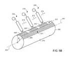
- FIG. 6Aillustrates the deposition of metallic material as a weld deposit onto at least a region of a surface of an alloy ingot.
- Alloy ingot 300is shown having a long axis 301 and a circumferential surface 370 .
- a deposit of metallic material 350is shown deposited in a helical fashion onto the circumferential surface 370 of the ingot 300 .
- Welding torch 310deposits the metallic material layer 350 onto the circumferential surface 370 as the welding torch 310 moves parallel to long axis 301 , as indicated by arrow 312 , while the ingot 300 simultaneously rotates about long axis 301 , as indicated by arrow 302 .
- the welding torch 310moves as indicated by arrow 312 and the ingot 300 rotates as indicated by arrow 302 until a layer of metallic material 350 is deposited along generally the entire circumferential surface 370 ( FIG. 6B ).
- An alloy ingot including a metallic material layer deposited onto at least a region of a surface of the alloy ingotmay be hot worked by applying force to the alloy ingot.
- Forcemay be applied to an alloy ingot in at least one region of at least one surface of the alloy ingot having a metallic material layer deposited onto at least one region.
- forcemay be applied to an ingot by applying the force to the metallic material layer deposited onto the ingot.
- a hot working operationmay comprise a forging operation and/or an extrusion operation.
- an alloy ingot having a metallic material layer deposited onto at least a region of a surface of the alloy ingotmay be upset forged and/or draw forged.
- An upset-and-draw forging operationmay comprise one or more sequences of an upset forging operation and one or more sequences of a draw forging operation.
- the end surfaces of an ingotmay be in contact with forging dies that apply force to the ingot that compresses the length of the ingot and increases the cross-section of the ingot.
- the side surfacese.g., the circumferential surface of a cylindrical ingot
- forging diesthat apply force to the ingot that compresses the cross-section of the ingot and increases the length of the ingot.
- FIGS. 7A and 7Cillustrate an upset forging operation.
- Forging dies 480 / 480 ′apply force to the opposed ends of an ingot 400 / 400 ′. The force is applied generally parallel to the long axis 401 / 401 ′ of the ingot 400 / 400 ′, as indicated by arrows 485 / 485 ′.
- FIG. 7Ashows an ingot 400 without a deposited metallic material layer on opposed ends of the ingot 400 .
- FIG. 7Cshows an ingot 400 ′ including metallic material layers 450 deposited onto the opposed ends of the ingot 400 ′.
- the ends of the ingot 400are in contact with the forging dies 480 ( FIG. 7A ).
- the metallic material layers 450are in contact with the forging dies 480 ′ ( FIG. 7C ).
- FIGS. 7B and 7Dillustrate a die-contacting surface of each of the ingots 400 and 400 ′ after upset forging as illustrated in FIGS. 7A and 7C , respectively.
- the die-contacting surface 490 of the ingot 400exhibits surface cracking.
- the die-contacting surface 490 ′ of the ingot 400 ′which includes metallic material layer 450 , does not exhibit surface cracking.
- the deposited metallic material layer 450reduces the incidence of surface cracking in a forged alloy ingot relative to an otherwise identical forged alloy ingot lacking such a metallic material layer.
- FIGS. 8A and 8Cillustrate a draw forging operation.
- Forging dies 580 / 580 ′apply force to an ingot 500 / 500 ′.
- the forceis applied generally perpendicular to the long axis 501 / 501 ′ of the ingot 500 / 500 ′, as indicated by arrows 585 / 585 ′.
- the forging dies 580 / 580 ′apply force to the ingot 500 / 500 ′ along generally the entire length of the ingot 500 / 500 ′ by moving generally parallel to the long axis 501 / 501 ′ of the ingot 500 / 500 ′, as indicated by arrows 587 / 587 ′.
- FIG. 8Ashows an ingot 500 without a metallic material layer.
- FIG. 8Cshows an ingot 500 ′ having a metallic material layer 550 deposited onto a circumferential surface of the ingot 500 ′.
- the circumferential surface of the ingot 500is in contact with the forging dies 580 ( FIG. 8A ).
- the metallic material layer 550is in contact with the forging dies 580 ′ ( FIG. 8C ).
- FIGS. 8B and 8Dillustrate the die-contacting surfaces of the ingots 500 and 500 ′ after draw forging as illustrated in FIGS. 8A and 8C , respectively.
- the die-contacting surface 590 of the ingot 500exhibits surface cracking.
- the die-contacting surface 590 ′ of the ingot 500 ′which includes metallic material layer 550 , does not exhibit surface cracking.
- the deposited metallic material layer 550reduces the incidence of surface cracking in a forged alloy ingot relative to an otherwise identical forged alloy ingot lacking such a metallic material layer.
- an ingot having a metallic material layer deposited onto at least a region of a surface of the ingotmay be subjected to one or more upset-and-draw forging operations.
- an ingotmay be first upset forged and then draw forged.
- the upset and draw sequencemay be repeated twice more for a total of three sequential upset and draw forging operations.
- One or more of the die-contacting surfaces of the ingotmay have a metallic material layer deposited onto the die-contacting surfaces of the ingot before the ingot is forged.
- an ingot having a metallic material layer deposited onto at least a region of a surface of the ingotmay be subjected to one or more extrusion operations.
- a cylindrical ingotmay be forced through a circular die, thereby decreasing the diameter and increasing the length of the ingot.
- One or more of the die-contacting surfaces of the ingotmay have a metallic material layer deposited onto die-contacting surfaces of the ingot before the ingot is extruded.
- the methods and processes described hereinmay be used to produce a wrought billet from a cast, consolidated, or spray formed ingot.
- the forge conversion or extrusion conversion of an ingot to a billet or other worked articlemay produce a finer grain structure in the article as compared to the former ingot.
- the methods and processes described hereinmay improve the yield of forged or extruded products (such as, for example, billets) from alloy ingots because the metallic material layer may reduce the incidence of surface cracking of the ingot during the forging and/or extrusion operations.
- a relatively more ductile metallic material layer deposited onto at least a region of a surface of a relatively less ductile alloy ingotmay more readily tolerate the strain induced by working dies. It also has been observed that a metallic material layer deposited onto at least a region of a surface of an alloy ingot may also more readily tolerate the temperature differential between the working dies and the ingot during hot working. In this manner, it has been observed that a deposited metallic material layer may exhibit zero or minor surface cracking while surface crack initiation is prevented or reduced in the underlying ingot during working.
- At least a portion of a deposited metallic material layermay be removed from the product formed from the ingot during the hot working.
- a grinding, peeling, and/or turning operationmay be used to remove at least a portion of the metallic material layer.
- at least a portion of a deposited metallic material layermay be removed from a billet formed by working an ingot by peeling (lathe-turning) and/or grinding the billet.
- ingots having a deposited metallic material layermay be hot worked to form products that may be used to fabricate various articles.
- the processes described hereinmay be used to form nickel base, iron base, nickel-iron base, or cobalt base alloy or superalloy billets.
- Billets or other products formed from hot worked ingotsmay be used to fabricate articles including, but not limited to, turbine components, such as, for example, disks and rings for turbine engines and various land based turbines.
- Other articles fabricated from ingots processed according to various embodiments described hereinmay include, but are not limited to, valves, engine components, shafts, and fasteners.
- Embodiments disclosed hereinare also directed to an ingot processing system and an ingot processing apparatus.
- the ingot processing system and apparatusmay comprise an ingot positioning apparatus and a welding apparatus.
- the ingot positioning apparatusmay comprise an ingot rotating apparatus configured to rotate an ingot about a long axis of the ingot.
- the welding apparatusmay be configured to deposit a metallic material layer as a weld deposit onto at least a region of a surface of an ingot.
- the ingot rotating apparatusmay comprise a lathe configured to rotate an ingot about the long axis of the ingot.
- the ingot rotating apparatusmay rotate the ingot continuously through one or more full rotations, or the ingot rotating device may discontinuously rotate the ingot sequentially through predetermined index angles, depending, for example, upon the configuration of the welding apparatus.
- At least one welding torchmay be a MIG welding torch. At least one welding torch may have a wire feed. At least one welding torch may be positioned a predetermined distance from a surface of an ingot. At least one welding torch may be configured with a predetermined wire feed rate, a predetermined wire voltage, and/or a predetermined inert gas purge flow rate. The torch-ingot surface distance, wire feed rate, voltage, inert gas purge flow rate, and/or various other welding operation parameters may be predetermined so that a metallic material layer is uniformly weld deposited onto the ingot. The identity of various other welding operation parameters may depend upon the particular type of welding operation utilized (e.g., MIG, TIG, etc.).
- the heat input (e.g., energy per unit length) used in the particular welding operationmay be maintained substantially uniform over the surface of the ingot onto which the metallic material is weld deposited. In this manner, weld-associated cracking of the underlying ingot surface may be reduced or eliminated, and the quality of the metallurgical bond between the underlying ingot and the weld deposit may be enhanced. In various embodiments, the heat input to the ingot during a welding operation may be minimized.
- the ingot processing systemmay comprise a control system.
- the control systemmay be configured to move and position the welding apparatus in conjunction with the ingot positioning apparatus to uniformly deposit a metallic material layer onto at least a region of a surface of the ingot.
- the control systemmay control the torch-surface distance, welding operation parameters, the movement and position of at least one welding torch relative to an ingot surface, and/or the movement and positioning of an ingot.
- the control systemmay be configured to move at least one welding torch in a generally linear manner parallel to the long axis of an ingot and along a region of the circumferential surface of the ingot parallel to the long axis.
- the control systemmay also be configured to position at least one welding torch to deposit metallic material as a weld deposit onto opposed end surfaces of an ingot.
- control systemmay be configured to control at least one welding torch to uniformly deposit the metallic material onto a rough surface of the ingot.
- the wire feed rate of a consumable electrode in a MIG welding torch, the voltage of the wire electrode, the torch-ingot surface distance, and the torch movement/positioningmay be actively controlled to deliver a stable arc over a rotating or stationary ingot. In this manner, a substantially uniform layer of metallic material may be deposited onto the ingot.
- the control systemmay be configured to automate the deposition of a metallic material layer as a weld deposit onto at least one end of an alloy ingot.
- the control systemmay be configured to automate the deposition of a metallic material layer as a weld deposit onto a circumferential surface of a cylindrical alloy ingot.
- the ingot processing systemmay deposit another ring-shaped layer of the metallic material onto the circumferential surface of the cylindrical ingot.
- the ingot processing systemmay be configured to repeat the re-positioning of at least one welding torch and the deposition of ring-shaped metallic material layers in an automated manner until the circumferential surface of a cylindrical ingot is substantially covered with a metallic material layer.
- the ingot processing systemmay be configured to deposit metallic material as a weld deposit onto a first region of a circumferential surface of a stationary ingot along a direction parallel to a long axis of the ingot using at least one welding torch configured to move parallel to the long axis of the ingot and along the first region. In this manner, the ingot processing system may deposit a layer of the metallic material onto the first region of the circumferential surface of the cylindrical ingot.
- the ingot processing systemmay be configured to re-position the cylindrical ingot to move the first region of the circumferential surface away from at least one welding torch and to move a second region of the circumferential surface toward at least one welding torch. For example, the ingot may be rotated through a predetermined index angle by the ingot rotating device.
- the ingot processing systemmay be configured to deposit metallic material as a weld deposit onto a surface of an ingot by rotating the ingot about a long axis of the ingot and simultaneously moving the welding torch parallel to a long axis of the ingot.
- the metallic material layermay be deposited using at least one moving welding torch under the control of the control system. In this manner, a deposit of metallic material may be deposited in a helical fashion onto the circumferential surface of the cylindrical ingot as the ingot rotates about the long axis and as at least one welding torch moves parallel to the long axis.
- Three-inch cubes of Rene 88TM alloywere used in a hot working operation.
- the cubeswere randomly cut from scrap portions of a Rene 88TM billet.
- the cubeswere heat treated at 2100° F. for 4 hours to increase the grain size of the alloy cubes to match the workability characteristics of a Rene 88TM ingot.
- One face surface of each cubewas conditioned by grinding on a disk grinder followed by sanding with a belt sander.
- a TechAlloy 606TM alloy layerwas deposited as a weld deposit onto the conditioned face surface of each cube using MIG welding (0.045 inch diameter TechAlloy 606 wire, 220 inch-per-minute, 18V wire voltage, 50 cubic feet per minute argon purge).
- FIG. 9Ais a photograph of two 3-inch cubes of Rene 88TM alloy each having TechAlloy 606TM alloy layers weld deposited onto the top surfaces as oriented in the photograph.
- a Rene 88TM alloy cube having a TechAlloy 606TM alloy layerwas heated to 2000° F. over a one-hour period and press forged at temperature.
- the face surface having the TechAlloy 606TM alloy layerwas placed in contact with the bottom die and the opposite face surface, which lacked a TechAlloy 606TM alloy layer, was placed in contact with the upper die.
- the 3-inch cubewas press forged to a 1-inch pancake using an approximately 1-inch-per-second strain rate.
- FIGS. 10A and 10Bare photographs of opposing sides of a 1-inch pancake pressed forged from a 3-inch cube.
- FIG. 10Ashows the non-layered side surface of the pancake
- FIG. 10Bshows the side surface having the TechAlloy 606TM alloy layer.
- the crack sensitivity of the Rene 88TM alloyis visible on the forged, non-layered surface shown in FIG. 10A .
- Surface crackingis clearly visible on the surface lacking a TechAlloy 606TM alloy layer as shown in FIG. 10A .
- the TechAlloy 606TM alloy layersubstantially reduced the incidence of surface cracking of the alloy during the forging.
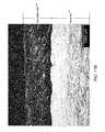
- FIG. 11Ais a photograph of a sectioned 1-inch pancake pressed forged from a 3-inch alloy cube as described above.
- the interface between the TechAlloy 606TM alloy layer and the underlying forged Rene 88TMwas imaged using optical microscopy at a mid-radius location (labeled “ 11 B” in FIG. 11A ), which corresponded to the cross-section of the welded surface of the pancake (the top surface as oriented in the photograph).
- FIG. 11Bis a micrograph taken at the mid-radius location as indicated in FIG. 11A .
Landscapes
- Engineering & Computer Science (AREA)
- Chemical & Material Sciences (AREA)
- Mechanical Engineering (AREA)
- Materials Engineering (AREA)
- Metallurgy (AREA)
- Organic Chemistry (AREA)
- Physics & Mathematics (AREA)
- Crystallography & Structural Chemistry (AREA)
- Manufacturing & Machinery (AREA)
- Plasma & Fusion (AREA)
- Thermal Sciences (AREA)
- Forging (AREA)
- Manufacture And Refinement Of Metals (AREA)
- Arc Welding In General (AREA)
- Turbine Rotor Nozzle Sealing (AREA)
- Extrusion Of Metal (AREA)
Abstract
Description
Claims (21)
Priority Applications (2)
| Application Number | Priority Date | Filing Date | Title |
|---|---|---|---|
| US15/048,210US11059088B2 (en) | 2010-02-05 | 2016-02-19 | Systems and methods for processing alloy ingots |
| US16/540,099US11059089B2 (en) | 2010-02-05 | 2019-08-14 | Systems and methods for processing alloy ingots |
Applications Claiming Priority (2)
| Application Number | Priority Date | Filing Date | Title |
|---|---|---|---|
| US12/700,963US9267184B2 (en) | 2010-02-05 | 2010-02-05 | Systems and methods for processing alloy ingots |
| US15/048,210US11059088B2 (en) | 2010-02-05 | 2016-02-19 | Systems and methods for processing alloy ingots |
Related Parent Applications (1)
| Application Number | Title | Priority Date | Filing Date |
|---|---|---|---|
| US12/700,963ContinuationUS9267184B2 (en) | 2010-02-05 | 2010-02-05 | Systems and methods for processing alloy ingots |
Related Child Applications (1)
| Application Number | Title | Priority Date | Filing Date |
|---|---|---|---|
| US16/540,099ContinuationUS11059089B2 (en) | 2010-02-05 | 2019-08-14 | Systems and methods for processing alloy ingots |
Publications (2)
| Publication Number | Publication Date |
|---|---|
| US20160167100A1 US20160167100A1 (en) | 2016-06-16 |
| US11059088B2true US11059088B2 (en) | 2021-07-13 |
Family
ID=43706790
Family Applications (3)
| Application Number | Title | Priority Date | Filing Date |
|---|---|---|---|
| US12/700,963Active2031-12-10US9267184B2 (en) | 2010-02-05 | 2010-02-05 | Systems and methods for processing alloy ingots |
| US15/048,210Active2031-04-22US11059088B2 (en) | 2010-02-05 | 2016-02-19 | Systems and methods for processing alloy ingots |
| US16/540,099ActiveUS11059089B2 (en) | 2010-02-05 | 2019-08-14 | Systems and methods for processing alloy ingots |
Family Applications Before (1)
| Application Number | Title | Priority Date | Filing Date |
|---|---|---|---|
| US12/700,963Active2031-12-10US9267184B2 (en) | 2010-02-05 | 2010-02-05 | Systems and methods for processing alloy ingots |
Family Applications After (1)
| Application Number | Title | Priority Date | Filing Date |
|---|---|---|---|
| US16/540,099ActiveUS11059089B2 (en) | 2010-02-05 | 2019-08-14 | Systems and methods for processing alloy ingots |
Country Status (19)
| Country | Link |
|---|---|
| US (3) | US9267184B2 (en) |
| EP (1) | EP2531319B1 (en) |
| JP (1) | JP5894087B2 (en) |
| KR (1) | KR101661794B1 (en) |
| CN (1) | CN102741005B (en) |
| AU (1) | AU2011213196B2 (en) |
| BR (1) | BR112012019283B1 (en) |
| CA (1) | CA2786742C (en) |
| DK (1) | DK2531319T3 (en) |
| ES (1) | ES2699697T3 (en) |
| HU (1) | HUE042127T2 (en) |
| IL (2) | IL220844A (en) |
| MX (1) | MX338478B (en) |
| PL (1) | PL2531319T3 (en) |
| PT (1) | PT2531319T (en) |
| RU (1) | RU2599925C2 (en) |
| TW (2) | TWI630963B (en) |
| UA (1) | UA111712C2 (en) |
| WO (1) | WO2011097085A1 (en) |
Families Citing this family (16)
| Publication number | Priority date | Publication date | Assignee | Title |
|---|---|---|---|---|
| US9267184B2 (en) | 2010-02-05 | 2016-02-23 | Ati Properties, Inc. | Systems and methods for processing alloy ingots |
| US8230899B2 (en) | 2010-02-05 | 2012-07-31 | Ati Properties, Inc. | Systems and methods for forming and processing alloy ingots |
| US10207312B2 (en) | 2010-06-14 | 2019-02-19 | Ati Properties Llc | Lubrication processes for enhanced forgeability |
| US8789254B2 (en) | 2011-01-17 | 2014-07-29 | Ati Properties, Inc. | Modifying hot workability of metal alloys via surface coating |
| JP5973717B2 (en)* | 2011-12-16 | 2016-08-23 | 株式会社Uacj | Aluminum alloy composite and manufacturing method thereof, aluminum alloy forged product |
| US9539636B2 (en) | 2013-03-15 | 2017-01-10 | Ati Properties Llc | Articles, systems, and methods for forging alloys |
| US9027374B2 (en) | 2013-03-15 | 2015-05-12 | Ati Properties, Inc. | Methods to improve hot workability of metal alloys |
| US9765416B2 (en)* | 2015-06-24 | 2017-09-19 | Ati Properties Llc | Alloy melting and refining method |
| EP3141335B1 (en) | 2015-09-08 | 2021-04-14 | Deutsche Edelstahlwerke Specialty Steel GmbH & Co. KG | Method for producing a component having a core section made of steel |
| US10587180B2 (en) | 2016-05-13 | 2020-03-10 | Otis Elevator Company | Magnetic elevator drive member and method of manufacture |
| WO2018061540A1 (en)* | 2016-09-29 | 2018-04-05 | 日立金属株式会社 | HOT EXTRUSION-MOLDING METHOD FOR Ni-BASED SUPER HEAT-RESISTANT ALLOY AND PRODUCTION METHOD FOR Ni-BASED SUPER HEAT-RESISTANT ALLOY EXTRUSION MATERIAL |
| US20190232349A1 (en)* | 2016-09-30 | 2019-08-01 | Hitachi Metals, Ltd. | Method of manufacturing ni-based super heat resistant alloy extruded material, and ni-based super heat resistant alloy extruded material |
| JP6873859B2 (en)* | 2017-07-31 | 2021-05-19 | 株式会社東芝 | Welding equipment and welding method |
| JP7381422B2 (en)* | 2020-08-28 | 2023-11-15 | 株式会社神戸製鋼所 | Manufacturing method of modeled object and modeled object |
| CN116652456B (en)* | 2023-04-12 | 2024-10-29 | 中国石油大学(华东) | Pipeline outer wall surfacing technology |
| CN118222798B (en)* | 2024-05-24 | 2024-08-06 | 成都先进金属材料产业技术研究院股份有限公司 | UNS N08367 alloy plate and preparation method thereof |
Citations (229)
| Publication number | Priority date | Publication date | Assignee | Title |
|---|---|---|---|---|
| US899827A (en) | 1908-04-23 | 1908-09-29 | Frank Cutter | Process of making ingots. |
| US2191478A (en) | 1938-08-26 | 1940-02-27 | Kellogg M W Co | Apparatus for producing composite metal articles |
| US2295702A (en) | 1939-09-01 | 1942-09-15 | Haynes Stellite Co | Method of and apparatus for applying metal coatings |
| GB684013A (en) | 1950-03-10 | 1952-12-10 | Comptoir Ind Etirage | Hot deformation of metals |
| US2630220A (en) | 1949-01-19 | 1953-03-03 | Comptoir Ind Etirage | Lubricating process with fibrous material in the hot extrusion of metals |
| US2653026A (en) | 1950-03-20 | 1953-09-22 | Abram M Feltus | Aerial target |
| US2706850A (en) | 1950-03-10 | 1955-04-26 | Comptoir Ind Etirage | Hot deformation of metals |
| US2893555A (en) | 1955-04-20 | 1959-07-07 | Comptoir Ind Etirage | Lubrication in the hot extrusion of metals |
| US3001059A (en) | 1956-08-20 | 1961-09-19 | Copperweld Steel Co | Manufacture of bimetallic billets |
| US3021594A (en) | 1958-02-05 | 1962-02-20 | Brev Cls Soc D Expl Des | Metal-shaping lubricant compositions and method |
| US3067473A (en) | 1960-03-29 | 1962-12-11 | Firth Sterling Inc | Producing superior quality ingot metal |
| US3105048A (en) | 1961-01-23 | 1963-09-24 | Engelhard Ind Inc | Solid lubricant |
| US3122828A (en) | 1963-01-14 | 1964-03-03 | Special Metals Inc | Conversion of heat-sensitive alloys with aid of a thermal barrier |
| US3127015A (en) | 1964-03-31 | schieren | ||
| US3181324A (en) | 1963-02-28 | 1965-05-04 | Johns Manville | Lubricant pad for extruding hot metals |
| US3339271A (en) | 1964-07-01 | 1967-09-05 | Wyman Gordon Co | Method of hot working titanium and titanium base alloys |
| US3390079A (en) | 1964-07-20 | 1968-06-25 | Utakoji Masaru | Method of hot extrusion of metallic articles |
| US3423975A (en) | 1965-04-22 | 1969-01-28 | Cefilac | Method of hot-extruding metals which require a low rate of deformation |
| US3431597A (en) | 1966-02-07 | 1969-03-11 | Dow Chemical Co | Apparatus for dispensing viscous materials into molds |
| US3446606A (en) | 1965-07-14 | 1969-05-27 | United Aircraft Corp | Refractory metal articles having oxidation-resistant coating |
| US3493713A (en) | 1967-02-20 | 1970-02-03 | Arcos Corp | Electric arc overlay welding |
| GB1202080A (en) | 1967-12-22 | 1970-08-12 | Wiggin & Co Ltd Henry | Forging billets |
| GB1207675A (en) | 1967-03-16 | 1970-10-07 | Int Combustion Holdings Ltd | Improvements in or relating to methods and apparatus for the manufacture of composite metal tubing |
| US3566661A (en) | 1968-07-29 | 1971-03-02 | Budd Co | Metal forming |
| US3617685A (en) | 1970-08-19 | 1971-11-02 | Chromalloy American Corp | Method of producing crack-free electron beam welds of jet engine components |
| US3690135A (en) | 1970-04-16 | 1972-09-12 | Johns Manville | Die pad for extruding hot metals |
| US3693419A (en) | 1970-12-30 | 1972-09-26 | Us Air Force | Compression test |
| US3752216A (en) | 1969-05-14 | 1973-08-14 | Sandel Ind Inc | Apparatus for homogeneous refining and continuously casting metals and alloys |
| JPS4892261A (en) | 1972-03-08 | 1973-11-30 | ||
| US3814212A (en) | 1972-05-12 | 1974-06-04 | Universal Oil Prod Co | Working of non-ferrous metals |
| SU435288A1 (en) | 1973-04-02 | 1974-07-05 | METHOD OF OBTAINING BIMETALLIC SLITECKS OF ENOERTO | |
| US3863325A (en) | 1973-05-25 | 1975-02-04 | Aluminum Co Of America | Glass cloth in metal forging |
| US3869393A (en) | 1970-05-21 | 1975-03-04 | Everlube Corp Of America | Solid lubricant adhesive film |
| US3945240A (en) | 1972-10-16 | 1976-03-23 | United Technologies Corporation | Diffusion bonding separator |
| US3959543A (en) | 1973-05-17 | 1976-05-25 | General Electric Company | Non-linear resistance surge arrester disc collar and glass composition thereof |
| US3979815A (en) | 1974-07-22 | 1976-09-14 | Nissan Motor Co., Ltd. | Method of shaping sheet metal of inferior formability |
| US3992202A (en) | 1974-10-11 | 1976-11-16 | Crucible Inc. | Method for producing aperture-containing powder-metallurgy article |
| GB1472939A (en) | 1974-08-21 | 1977-05-11 | Osprey Metals Ltd | Method for making shaped articles from sprayed molten metal |
| JPS52114524A (en) | 1976-03-24 | 1977-09-26 | Hitachi Ltd | Production method of steel ingot by vacuum arc melting method |
| US4055975A (en) | 1977-04-01 | 1977-11-01 | Lockheed Aircraft Corporation | Precision forging of titanium |
| US4060250A (en) | 1976-11-04 | 1977-11-29 | De Laval Turbine Inc. | Rotor seal element with heat resistant alloy coating |
| JPS52147556A (en) | 1976-06-02 | 1977-12-08 | Kobe Steel Ltd | Hollow billet preupset process |
| JPS53108842A (en) | 1977-03-05 | 1978-09-22 | Kobe Steel Ltd | Manufacture of steel materials having coated stainless steel layer |
| JPS5452656A (en) | 1977-10-05 | 1979-04-25 | Kobe Steel Ltd | Manufacture of steel products covered by stainless steel |
| US4160048A (en) | 1976-12-21 | 1979-07-03 | Eutectic Corporation | Method of making a composite cast iron dryer or the like |
| US4217318A (en) | 1975-02-28 | 1980-08-12 | Honeywell Inc. | Formation of halide optical elements by hydrostatic press forging |
| JPS55122661A (en) | 1979-03-15 | 1980-09-20 | Sumitomo Metal Ind Ltd | Steel ingot for rolled wheel and production thereof |
| US4226758A (en) | 1977-02-23 | 1980-10-07 | Gandy Frictions Limited | Friction material |
| US4257812A (en) | 1979-01-17 | 1981-03-24 | The Babcock & Wilcox Company | Fibrous refractory products |
| JPS56109128A (en) | 1980-02-04 | 1981-08-29 | Sankin Kogyo Kk | Lubricant for warm and hot forging work |
| JPS57112923A (en) | 1980-12-29 | 1982-07-14 | Nippon Steel Corp | Glass lubricant for hot extrusion |
| JPS57209736A (en) | 1981-06-19 | 1982-12-23 | Mitsubishi Heavy Ind Ltd | Hot plastic working method for metallic material |
| US4377371A (en) | 1981-03-11 | 1983-03-22 | The United States Of America As Represented By The Administrator Of The National Aeronautics And Space Administration | Laser surface fusion of plasma sprayed ceramic turbine seals |
| SU1015951A1 (en) | 1981-07-21 | 1983-05-07 | Всесоюзный научно-исследовательский и проектный институт тугоплавких металлов и твердых сплавов | Method of producing articles from hard-to-deform materials |
| JPS58143012U (en) | 1982-03-16 | 1983-09-27 | 住友金属工業株式会社 | Lubricant application equipment for punched pipe materials |
| JPS596724B2 (en) | 1978-02-14 | 1984-02-14 | 株式会社神戸製鋼所 | Holobilet expansion tool |
| SU1076162A1 (en) | 1982-12-24 | 1984-02-29 | Уральский научно-исследовательский институт трубной промышленности | Method of continuous production of welded vitrified tubes |
| JPS5922958Y2 (en) | 1977-03-10 | 1984-07-09 | 山内ゴム工業株式会社 | Cushion material for molding presses |
| JPS59179214A (en) | 1983-03-30 | 1984-10-11 | Sumitomo Metal Ind Ltd | Manufacture of pipe by hot extrusion |
| EP0128682A1 (en) | 1983-06-10 | 1984-12-19 | Inco Alloys International, Inc. | Method for removing glass lubricants from extrusions |
| JPS59227992A (en) | 1983-06-08 | 1984-12-21 | Agency Of Ind Science & Technol | Lubricant for plastic working |
| US4544523A (en) | 1983-10-17 | 1985-10-01 | Crucible Materials Corporation | Cladding method for producing a lined alloy article |
| JPS6047012B2 (en) | 1980-04-15 | 1985-10-19 | 株式会社神戸製鋼所 | High-temperature lubrication extrusion method for alloy steel, steel, and heat-resistant alloys |
| JPS60215557A (en) | 1984-04-06 | 1985-10-28 | Dai Ichi Kogyo Seiyaku Co Ltd | Glass fiber binder |
| CN85103156A (en) | 1985-04-21 | 1986-03-10 | 李声寿 | Improve a kind of simple new technology of high-temperature alloy forging quality |
| JPS61148407U (en) | 1985-03-05 | 1986-09-12 | ||
| JPS61255757A (en) | 1985-05-07 | 1986-11-13 | Nippon Kokan Kk <Nkk> | Drop casting method |
| JPS61269929A (en) | 1985-05-24 | 1986-11-29 | Nippon Parkerizing Co Ltd | Lubricating treatment of metallic material |
| SU1299985A1 (en) | 1985-07-11 | 1987-03-30 | Симферопольский государственный университет им.М.В.Фрунзе | Method for manufacturing optical components |
| JPS62230450A (en) | 1986-03-31 | 1987-10-09 | Sumitomo Metal Ind Ltd | Piercing method in punched pipe |
| GB2190319A (en) | 1986-05-16 | 1987-11-18 | Derek Harry Graddon Redman | Apparatus for weld cladding on metal surfaces |
| US4728448A (en) | 1986-05-05 | 1988-03-01 | The United States Of America As Represented By The Administrator Of The National Aeronautics And Space Administration | Carbide/fluoride/silver self-lubricating composite |
| US4744504A (en) | 1985-01-24 | 1988-05-17 | Turner William C | Method of manufacturing a clad tubular product by extrusion |
| US4780484A (en) | 1987-01-27 | 1988-10-25 | Mankiewicz Gebr. & Co. (Gmbh & Co. Kg) | Molding material and its use as construction and repair material |
| JPS6428382A (en) | 1987-07-24 | 1989-01-30 | Honda Motor Co Ltd | Method for coating stock for hot plastic working |
| US4843856A (en) | 1987-10-26 | 1989-07-04 | Cameron Iron Works Usa, Inc. | Method of forging dual alloy billets |
| JPH01254337A (en) | 1988-04-04 | 1989-10-11 | Daido Steel Co Ltd | Forging method |
| JPH01271021A (en) | 1988-04-21 | 1989-10-30 | Mitsubishi Heavy Ind Ltd | Method for forging super heat-resistant alloy |
| JPH01274319A (en) | 1988-04-25 | 1989-11-02 | Fujikura Ltd | Manufacturing method of fiber-dispersed superconducting wire |
| SU1540977A1 (en) | 1988-05-05 | 1990-02-07 | Всесоюзный Сельскохозяйственный Институт Заочного Образования | Apparatus for building up surfaces of bodies of rotation |
| JPH02104435A (en) | 1988-10-11 | 1990-04-17 | Mitsubishi Steel Mfg Co Ltd | Lubrication method for hot forming of titanium alloys |
| JPH02107795A (en) | 1988-10-14 | 1990-04-19 | Tohoku Ricoh Co Ltd | Copper-tin alloy plating bath |
| US4935198A (en) | 1986-09-03 | 1990-06-19 | Avesta Nyby Powder Ab | Method for the powder-metallurgical manufacture of tubes or like elongated profiles |
| US4943452A (en) | 1987-08-18 | 1990-07-24 | Shin-Etsu Chemical Co., Ltd. | Method for improving composite materials by use of a silane coupling agent |
| EP0386515A2 (en) | 1989-03-04 | 1990-09-12 | Fried. Krupp Gesellschaft mit beschränkter Haftung | Process for producing a metallic composite body having a region of high wear resistance and apparatus for carrying out the process |
| US4961991A (en) | 1990-01-29 | 1990-10-09 | Ucar Carbon Technology Corporation | Flexible graphite laminate |
| SU1606252A1 (en) | 1988-07-19 | 1990-11-15 | Специальное Конструкторско-Технологическое Бюро "Тантал" При Уфимском Авиационном Институте Им.Серго Орджоникидзе | Die heat insulation unit for isothermal forming |
| JPH0390212A (en) | 1989-09-01 | 1991-04-16 | Sumitomo Metal Ind Ltd | Method for hot-extruding close-packed hexagonal system metal |
| JPH03174938A (en) | 1989-12-02 | 1991-07-30 | Kobe Steel Ltd | Method for hot forging ni base super heat-resistant alloy |
| US5052464A (en) | 1988-05-11 | 1991-10-01 | Hitachi, Ltd. | Method of casting a member having an improved surface layer |
| JPH03277751A (en) | 1990-03-27 | 1991-12-09 | Mitsubishi Materials Corp | Production of electrode for remelting |
| JPH03297533A (en) | 1990-04-17 | 1991-12-27 | Mitsubishi Materials Corp | Forging die |
| JPH0413434A (en) | 1990-05-07 | 1992-01-17 | Mitsubishi Materials Corp | Isothermal forging method and lubricating sheet for isothermal forging |
| JPH0466607A (en) | 1990-07-06 | 1992-03-03 | Sumitomo Metal Ind Ltd | Production of highly corrosion resistant ni-base alloy tube |
| JPH04118133A (en) | 1990-09-07 | 1992-04-20 | Daido Steel Co Ltd | Lubricant for hot plastic working |
| WO1992007050A1 (en) | 1990-10-19 | 1992-04-30 | United Technologies Corporation | Rheologically controlled glass lubricant for hot metal working |
| US5141566A (en) | 1990-05-31 | 1992-08-25 | Sumitomo Metal Industries, Ltd. | Process for manufacturing corrosion-resistant seamless titanium alloy tubes and pipes |
| SU1761364A1 (en) | 1990-03-05 | 1992-09-15 | Производственное объединение "Новокраматорский машиностроительный завод" | Method of forging plate-type forced pieces |
| JPH054994A (en) | 1991-06-27 | 1993-01-14 | Nitto Boseki Co Ltd | Silane coupling agents and glass fiber products for laminated boards |
| JPH05147975A (en) | 1991-11-26 | 1993-06-15 | Nichias Corp | Heat resistant glass fiber |
| GB2262540A (en) | 1991-12-20 | 1993-06-23 | Rmi Titanium Co | Enhancement of hot workability of titanium alloy by coating with titanium |
| JPH05177289A (en) | 1991-12-26 | 1993-07-20 | Daido Steel Co Ltd | Heat loss prevention method in die forging |
| US5259965A (en) | 1990-09-21 | 1993-11-09 | Nissan Motor Co., Ltd. | Titanium lubricating material suitable for use in vacuum |
| US5263349A (en) | 1992-09-22 | 1993-11-23 | E. I. Du Pont De Nemours And Company | Extrusion of seamless molybdenum rhenium alloy pipes |
| JPH0663638A (en) | 1992-08-20 | 1994-03-08 | Nippon Muki Co Ltd | Metal tube manufacturing method and lubricant used for manufacturing the same |
| JPH0663743A (en) | 1992-08-13 | 1994-03-08 | Kanto Special Steel Works Ltd | Production method of composite roll for hot rolling |
| US5302414A (en) | 1990-05-19 | 1994-04-12 | Anatoly Nikiforovich Papyrin | Gas-dynamic spraying method for applying a coating |
| JPH06106232A (en) | 1992-09-24 | 1994-04-19 | Sumitomo Metal Ind Ltd | Hot extrusion pipe making method |
| JPH06154842A (en) | 1992-11-25 | 1994-06-03 | Nippon Steel Corp | Hot extrusion method |
| WO1994013849A1 (en) | 1992-12-14 | 1994-06-23 | United Technologies Corporation | Superalloy forging process and related composition |
| US5348446A (en) | 1993-04-28 | 1994-09-20 | General Electric Company | Bimetallic turbine airfoil |
| RU2020020C1 (en) | 1989-05-16 | 1994-09-30 | Самарский филиал Научно-исследовательского института технологии и организации производства двигателей | Method of hot pressing of heat resistance titanium alloys |
| JPH06277748A (en) | 1993-03-26 | 1994-10-04 | Furukawa Alum Co Ltd | Manufacture of extruded aluminum material and manufacturing device therefor |
| JPH06328125A (en) | 1993-05-24 | 1994-11-29 | Nkk Corp | Duplex stainless steel seamless steel pipe manufacturing method |
| US5374323A (en) | 1991-08-26 | 1994-12-20 | Aluminum Company Of America | Nickel base alloy forged parts |
| JPH073840A (en) | 1993-06-14 | 1995-01-06 | Fujita Corp | Crawler traveling type working machine |
| JPH0711403A (en) | 1993-06-29 | 1995-01-13 | Sumitomo Metal Ind Ltd | Method for producing Ni-base alloy having intergranular fracture resistance |
| JPH0788586A (en) | 1993-09-20 | 1995-04-04 | Kobe Steel Ltd | Hot upset forging method |
| JPH07171650A (en) | 1993-12-17 | 1995-07-11 | Kobe Steel Ltd | Hot swaging forging method |
| JPH07223018A (en) | 1994-02-14 | 1995-08-22 | Nippon Steel Corp | Glass lubricant for hot extrusion |
| WO1995035396A1 (en) | 1994-06-22 | 1995-12-28 | United Technologies Corporation | Nickel based alloy for repairing substrates |
| US5525779A (en) | 1993-06-03 | 1996-06-11 | Martin Marietta Energy Systems, Inc. | Intermetallic alloy welding wires and method for fabricating the same |
| RU2070461C1 (en) | 1993-11-12 | 1996-12-20 | Малое научно-производственное технологическое предприятие "ТЭСП" | Method to produce basic double layer antifriction coating for materials treatment under pressure |
| EP0767028A1 (en) | 1995-10-04 | 1997-04-09 | Societe Nationale D'etude Et De Construction De Moteurs D'aviation "Snecma" | Process for joining intermetallic materials by reaction sintering and derived applications |
| US5665180A (en) | 1995-06-07 | 1997-09-09 | The United States Of America As Represented By The Secretary Of The Air Force | Method for hot rolling single crystal nickel base superalloys |
| JPH09271981A (en) | 1996-04-10 | 1997-10-21 | Hitachi Ltd | Lead free solder and article using it |
| WO1998005463A1 (en) | 1996-08-05 | 1998-02-12 | Welding Services, Inc. | Dual pass weld overlay method and apparatus |
| US5743121A (en) | 1996-05-31 | 1998-04-28 | General Electric Company | Reducible glass lubricants for metalworking |
| US5743120A (en) | 1995-05-12 | 1998-04-28 | H.C. Starck, Inc. | Wire-drawing lubricant and method of use |
| US5783530A (en) | 1989-10-31 | 1998-07-21 | Alcan International Limited | Non-staining solid lubricants |
| US5799717A (en) | 1995-11-17 | 1998-09-01 | Techno Coat Company, Ltd. | Copper alloy mold for casting aluminum or aluminum alloy |
| JPH1110222A (en) | 1997-06-18 | 1999-01-19 | Sumitomo Metal Ind Ltd | Glass pad for hot extrusion |
| WO1999002743A1 (en) | 1997-07-11 | 1999-01-21 | Johnson Matthey Electronics, Inc. | Metal article with fine uniform structures and textures and process of making same |
| US5902762A (en) | 1997-04-04 | 1999-05-11 | Ucar Carbon Technology Corporation | Flexible graphite composite |
| US5908670A (en) | 1996-06-24 | 1999-06-01 | Tafa, Incorporated | Apparatus for rotary spraying a metallic coating |
| RU2133652C1 (en) | 1998-03-30 | 1999-07-27 | Товарищество с ограниченной ответственностью "Директ" | Method of obtaining cover fused onto article |
| US5951792A (en) | 1997-09-22 | 1999-09-14 | Asea Brown Boveri Ag | Method for welding age-hardenable nickel-base alloys |
| US5981081A (en) | 1984-09-18 | 1999-11-09 | Union Carbide Coatings Service Corporation | Transition metal boride coatings |
| US5989487A (en) | 1999-03-23 | 1999-11-23 | Materials Modification, Inc. | Apparatus for bonding a particle material to near theoretical density |
| JPH11320073A (en) | 1998-05-20 | 1999-11-24 | Aoki Kogyo Kk | Production of two-layered nickel-base alloy clad steel sheet by casting method |
| US6006564A (en) | 1998-12-10 | 1999-12-28 | Honda Of America Mfg., Inc. | Application of dry lubricant to forming dies and forging dies that operate with high force |
| EP0969114A2 (en) | 1998-06-30 | 2000-01-05 | Howmet Research Corporation | Nickel base superalloy preweld heat treatment |
| RU2145982C1 (en) | 1998-09-04 | 2000-02-27 | ОАО Верхнесалдинское металлургическое производственное объединение | Method of protection of slab surfaces |
| RU2145981C1 (en) | 1998-08-05 | 2000-02-27 | Открытое акционерное общество Верхнесалдинское металлургическое производственное объединение | Method of protection of surface of ingots |
| JP2000288674A (en) | 1999-04-02 | 2000-10-17 | Sumitomo Metal Ind Ltd | High-temperature plastic working method of metal and resin film used therefor |
| JP2000312905A (en) | 1999-04-26 | 2000-11-14 | Sumitomo Metal Ind Ltd | Hot working method of B-containing austenitic stainless steel |
| US6154959A (en) | 1999-08-16 | 2000-12-05 | Chromalloy Gas Turbine Corporation | Laser cladding a turbine engine vane platform |
| US6202277B1 (en) | 1999-10-28 | 2001-03-20 | General Electric Company | Reusable hard tooling for article consolidation and consolidation method |
| US6269669B1 (en) | 1998-04-06 | 2001-08-07 | Nisshinbo Industries, Inc. | Surface-treating method for back plate for friction material |
| US6296043B1 (en) | 1996-12-10 | 2001-10-02 | Howmet Research Corporation | Spraycast method and article |
| US6312022B1 (en) | 2000-03-27 | 2001-11-06 | Metex Mfg. Corporation | Pipe joint and seal |
| US6329079B1 (en) | 1999-10-27 | 2001-12-11 | Nooter Corporation | Lined alloy tubing and process for manufacturing the same |
| US6330818B1 (en) | 1998-12-17 | 2001-12-18 | Materials And Manufacturing Technologies Solutions Company | Lubrication system for metalforming |
| US20020005233A1 (en) | 1998-12-23 | 2002-01-17 | John J. Schirra | Die cast nickel base superalloy articles |
| US20020019321A1 (en) | 1998-02-17 | 2002-02-14 | Robert W. Balliett | Metalworking lubrication |
| WO2002027067A1 (en) | 2000-09-28 | 2002-04-04 | Japan Ultra-High Temperature Materials Research Institute | Heat-resistant material of niobium base alloy |
| EP1197570A2 (en) | 2000-10-13 | 2002-04-17 | General Electric Company | Nickel-base alloy and its use in forging and welding operations |
| US6418795B2 (en) | 2000-04-06 | 2002-07-16 | Korea Advanced Institute Of Science And Technology | Method of measuring shear friction factor through backward extrusion process |
| JP2002299019A (en) | 2001-03-30 | 2002-10-11 | Mitsui Eng & Shipbuild Co Ltd | Heating element insulation type induction heating furnace |
| US6484790B1 (en) | 1999-08-31 | 2002-11-26 | Cummins Inc. | Metallurgical bonding of coated inserts within metal castings |
| US6547952B1 (en) | 2001-07-13 | 2003-04-15 | Brunswick Corporation | System for inhibiting fouling of an underwater surface |
| JP2003239025A (en) | 2001-12-10 | 2003-08-27 | Sumitomo Titanium Corp | Method for melting metal of high melting point |
| JP2003260535A (en) | 2002-03-06 | 2003-09-16 | Toto Ltd | Production method for bottomed parts |
| US6623690B1 (en) | 2001-07-19 | 2003-09-23 | Crucible Materials Corporation | Clad power metallurgy article and method for producing the same |
| TW562714B (en) | 2000-06-07 | 2003-11-21 | Mitsubishi Materials Corp | Method and apparatus for manufacturing copper and/or copper alloy ingot having no shrinkage cavity and having smooth surface without wrinkles |
| JP2004067426A (en) | 2002-08-05 | 2004-03-04 | Asahi Schwebel Co Ltd | Glass filler |
| US20040079453A1 (en) | 2002-10-25 | 2004-04-29 | Groh Jon Raymond | Nickel-base alloy and its use in casting and welding operations |
| US20040105774A1 (en) | 2002-11-26 | 2004-06-03 | Del Corso Gregory J. | Process for improving the hot workability of a cast superalloy ingot |
| US6753504B2 (en) | 2001-03-14 | 2004-06-22 | Alstom Technology Ltd | Method for welding together two parts which are exposed to different temperatures, and turbomachine produced using a method of this type |
| US6774346B2 (en) | 2001-05-21 | 2004-08-10 | Thermal Solutions, Inc. | Heat retentive inductive-heatable laminated matrix |
| JP2005040810A (en) | 2003-07-24 | 2005-02-17 | Nippon Steel Corp | Metal plate for press working and method and apparatus for applying solid lubricant to the metal plate |
| US20050044800A1 (en) | 2003-09-03 | 2005-03-03 | Hall David R. | Container assembly for HPHT processing |
| US6865917B2 (en) | 2003-03-27 | 2005-03-15 | Ford Motor Company | Flanging and hemming process with radial compression of the blank stretched surface |
| JP2005066656A (en) | 2003-08-26 | 2005-03-17 | Aisan Ind Co Ltd | Manufacturing method of member made of metal containing titanium |
| US6933045B2 (en) | 2000-01-21 | 2005-08-23 | Nitto Boseki Co., Ltd. | Heat-resistant glass fiber and process for the production thereof |
| US6933058B2 (en) | 2003-12-01 | 2005-08-23 | General Electric Company | Beta-phase nickel aluminide coating |
| US20050273994A1 (en) | 2004-06-10 | 2005-12-15 | Bergstrom David S | Clad alloy substrates and method for making same |
| US7000306B2 (en) | 2002-12-18 | 2006-02-21 | Honeywell International, Inc. | Spun metal form used to manufacture dual alloy turbine wheel |
| RU2275997C2 (en) | 2004-07-14 | 2006-05-10 | Общество с ограниченной ответственностью фирма "Директ" | Automatic electric arc surfacing method for parts such as bodies of revolution |
| US7108483B2 (en) | 2004-07-07 | 2006-09-19 | Siemens Power Generation, Inc. | Composite gas turbine discs for increased performance and reduced cost |
| US7114548B2 (en) | 2004-12-09 | 2006-10-03 | Ati Properties, Inc. | Method and apparatus for treating articles during formation |
| US20060239852A1 (en) | 2000-11-18 | 2006-10-26 | Rolls-Royce, Plc | Nickel alloy composition |
| US7172820B2 (en) | 2003-11-25 | 2007-02-06 | General Electric Company | Strengthened bond coats for thermal barrier coatings |
| US7178376B2 (en) | 2005-01-14 | 2007-02-20 | Snecma | Forging press of the hot-die type and thermal insulation means for the press |
| JP2007054867A (en) | 2005-08-25 | 2007-03-08 | Jaroc:Kk | Swaging equipment for warm processing |
| US7188498B2 (en) | 2004-12-23 | 2007-03-13 | Gm Global Technology Operations, Inc. | Reconfigurable tools and/or dies, reconfigurable inserts for tools and/or dies, and methods of use |
| US7208116B2 (en) | 2000-09-29 | 2007-04-24 | Rolls-Royce Plc | Nickel base superalloy |
| US7257981B2 (en) | 2001-03-29 | 2007-08-21 | Showa Denko K.K. | Closed forging method, forging production system using the method, forging die used in the method and system, and preform or yoke produced by the method and system |
| WO2007098439A2 (en) | 2006-02-20 | 2007-08-30 | Superior Press & Automation, Inc. | Process and apparatus for scoring and breaking ingots |
| US7264888B2 (en) | 2004-10-29 | 2007-09-04 | General Electric Company | Coating systems containing gamma-prime nickel aluminide coating |
| US7288328B2 (en) | 2004-10-29 | 2007-10-30 | General Electric Company | Superalloy article having a gamma-prime nickel aluminide coating |
| US7316057B2 (en) | 2004-10-08 | 2008-01-08 | Siemens Power Generation, Inc. | Method of manufacturing a rotating apparatus disk |
| US20080070024A1 (en) | 2006-08-10 | 2008-03-20 | Curran William F | Layered fire retardant barrier panel |
| US7357958B2 (en) | 2004-10-29 | 2008-04-15 | General Electric Company | Methods for depositing gamma-prime nickel aluminide coatings |
| CN101195871A (en) | 2008-01-02 | 2008-06-11 | 西北有色金属研究院 | A kind of production method of clean titanium and titanium alloy ingot |
| RU2337158C2 (en) | 2006-11-24 | 2008-10-27 | ОАО "Златоустовый металлургический завод" | Method of production of bimetallic ingots |
| US7445434B2 (en) | 2003-03-24 | 2008-11-04 | Tocalo Co., Ltd. | Coating material for thermal barrier coating having excellent corrosion resistance and heat resistance and method of producing the same |
| JP2009066661A (en) | 2007-09-17 | 2009-04-02 | General Electric Co <Ge> | Forging die and forging method |
| CN101412066A (en) | 2007-10-17 | 2009-04-22 | 沈阳黎明航空发动机(集团)有限责任公司 | Hammer forging technique of GH4169 alloy dish |
| RU2355791C2 (en) | 2007-05-30 | 2009-05-20 | Открытое Акционерное Общество "Корпорация Всмпо-Ависма" | Method of manufacturing of high reactivity metals and alloys ingots and vacuum-arc-refining furnace for manufacturing of reactivity metals and alloys ingots |
| CN101517112A (en) | 2006-08-11 | 2009-08-26 | 联邦-蒙古尔烧结产品有限公司 | Improved powder metallurgy composition |
| CN101554491A (en) | 2009-05-27 | 2009-10-14 | 四川大学 | Method for preparing bioactive glass coating by liquid-phase thermal spray |
| US7611592B2 (en) | 2006-02-23 | 2009-11-03 | Ati Properties, Inc. | Methods of beta processing titanium alloys |
| US7618684B2 (en) | 2002-12-12 | 2009-11-17 | Innovatech, Llc | Method of forming a coating on a surface of a substrate |
| JP2010000519A (en) | 2008-06-20 | 2010-01-07 | Sanyo Special Steel Co Ltd | Method of inserting internal glass in hot extruded steel pipe |
| JP2010065135A (en) | 2008-09-10 | 2010-03-25 | Sumitomo Light Metal Ind Ltd | Lubricating mold release agent for hot-forging aluminum, and method for hot-forging aluminum therewith |
| US7770427B2 (en) | 2003-02-18 | 2010-08-10 | Showa Denko K.K. | Metal forged product, upper or lower arm, preform of the arm, production method for the metal forged product, forging die, and metal forged product production system |
| US20100236317A1 (en) | 2009-03-19 | 2010-09-23 | Sigelko Jeff D | Method for forming articles at an elevated temperature |
| US7803212B2 (en) | 2005-09-22 | 2010-09-28 | Ati Properties, Inc. | Apparatus and method for clean, rapidly solidified alloys |
| EP2286942A1 (en) | 2009-08-20 | 2011-02-23 | General Electric Company | Device and method for hot isostatic pressing container having adjustable volume and corner |
| RU2415967C2 (en) | 2009-06-08 | 2011-04-10 | Учреждение Российской Академии Наук Институт Проблем Сверхпластичности Металлов Ран | Procedure for covering work pieces out of metals and alloys with protective coating |
| US7927085B2 (en) | 2006-08-31 | 2011-04-19 | Hall David R | Formable sealant barrier |
| US20110171490A1 (en) | 2008-10-01 | 2011-07-14 | Thyssenkrupp Vdm Gmbh | Method for the production of composite metal semi-finished products |
| US20110195269A1 (en)* | 2010-02-05 | 2011-08-11 | Ati Properties, Inc. | Systems and methods for forming and processing alloy ingots |
| US8002166B2 (en) | 2004-12-28 | 2011-08-23 | Technical University Of Denmark | Method of producing metal to glass, metal to metal or metal to ceramic connections |
| US20110302978A1 (en) | 2010-06-14 | 2011-12-15 | Ati Properties, Inc. | Lubrication processes for enhanced forgeability |
| US20120073693A1 (en) | 2011-03-22 | 2012-03-29 | Owens Corning Intellectual Capital, Llc | Insulation and methods of insulating |
| US8303289B2 (en) | 2009-08-24 | 2012-11-06 | General Electric Company | Device and method for hot isostatic pressing container |
| US8327676B2 (en) | 2008-12-01 | 2012-12-11 | Sumitomo Metal Industries, Ltd. | Upper-end formed glass complex for hot expanding piercing and method of manufacturing billet for hot extrusion pipe making |
| US8327681B2 (en) | 2007-04-20 | 2012-12-11 | Shell Oil Company | Wellbore manufacturing processes for in situ heat treatment processes |
| US20130142686A1 (en) | 2011-12-02 | 2013-06-06 | Ati Properties, Inc. | Endplate for hot isostatic pressing canister, hot isostatic pressing canister, and hot isostatic pressing method |
| JP2013119100A (en) | 2011-12-07 | 2013-06-17 | Nippon Steel & Sumitomo Metal Corp | Hot drilling expansion apparatus |
| US8545994B2 (en) | 2009-06-02 | 2013-10-01 | Integran Technologies Inc. | Electrodeposited metallic materials comprising cobalt |
| US8567226B2 (en) | 2008-10-06 | 2013-10-29 | GM Global Technology Operations LLC | Die for use in sheet metal forming processes |
| US8789254B2 (en) | 2011-01-17 | 2014-07-29 | Ati Properties, Inc. | Modifying hot workability of metal alloys via surface coating |
| US20140271337A1 (en) | 2013-03-15 | 2014-09-18 | Ati Properties, Inc. | Articles, systems, and methods for forging alloys |
| US9027374B2 (en) | 2013-03-15 | 2015-05-12 | Ati Properties, Inc. | Methods to improve hot workability of metal alloys |
| US9267184B2 (en) | 2010-02-05 | 2016-02-23 | Ati Properties, Inc. | Systems and methods for processing alloy ingots |
| US9610630B2 (en) | 2010-12-28 | 2017-04-04 | Hitachi Metals, Ltd. | Closed-die forging method and method of manufacturing forged article |
Family Cites Families (4)
| Publication number | Priority date | Publication date | Assignee | Title |
|---|---|---|---|---|
| US279678A (en)* | 1883-06-19 | Flour-packer | ||
| US5489680A (en)* | 1992-10-13 | 1996-02-06 | American Home Products Corporation | Carbamates of rapamycin |
| US5743151A (en)* | 1996-08-12 | 1998-04-28 | Chrysler Corporation | Locking mechanism for tilt steering column |
| US6979477B2 (en)* | 2000-09-06 | 2005-12-27 | Urethane Soy Systems Company | Vegetable oil-based coating and method for application |
- 2010
- 2010-02-05USUS12/700,963patent/US9267184B2/enactiveActive
- 2011
- 2011-01-24AUAU2011213196Apatent/AU2011213196B2/enactiveActive
- 2011-01-24PTPT11703525Tpatent/PT2531319T/enunknown
- 2011-01-24WOPCT/US2011/022213patent/WO2011097085A1/enactiveApplication Filing
- 2011-01-24CACA2786742Apatent/CA2786742C/enactiveActive
- 2011-01-24UAUAA201210478Apatent/UA111712C2/enunknown
- 2011-01-24CNCN201180007922.XApatent/CN102741005B/enactiveActive
- 2011-01-24MXMX2012008902Apatent/MX338478B/enactiveIP Right Grant
- 2011-01-24RURU2012137783/02Apatent/RU2599925C2/enactive
- 2011-01-24ESES11703525Tpatent/ES2699697T3/enactiveActive
- 2011-01-24JPJP2012551996Apatent/JP5894087B2/enactiveActive
- 2011-01-24DKDK11703525.3Tpatent/DK2531319T3/enactive
- 2011-01-24KRKR1020127019425Apatent/KR101661794B1/ennot_activeExpired - Fee Related
- 2011-01-24EPEP11703525.3Apatent/EP2531319B1/enactiveActive
- 2011-01-24BRBR112012019283-3Apatent/BR112012019283B1/enactiveIP Right Grant
- 2011-01-24HUHUE11703525Apatent/HUE042127T2/enunknown
- 2011-01-24PLPL11703525Tpatent/PL2531319T3/enunknown
- 2011-02-01TWTW106111807Apatent/TWI630963B/ennot_activeIP Right Cessation
- 2011-02-01TWTW100104023Apatent/TWI584890B/ennot_activeIP Right Cessation
- 2012
- 2012-07-10ILIL220844Apatent/IL220844A/enactiveIP Right Grant
- 2016
- 2016-02-19USUS15/048,210patent/US11059088B2/enactiveActive
- 2017
- 2017-10-17ILIL255087Apatent/IL255087B/enactiveIP Right Grant
- 2019
- 2019-08-14USUS16/540,099patent/US11059089B2/enactiveActive
Patent Citations (247)
| Publication number | Priority date | Publication date | Assignee | Title |
|---|---|---|---|---|
| US3127015A (en) | 1964-03-31 | schieren | ||
| US899827A (en) | 1908-04-23 | 1908-09-29 | Frank Cutter | Process of making ingots. |
| US2191478A (en) | 1938-08-26 | 1940-02-27 | Kellogg M W Co | Apparatus for producing composite metal articles |
| US2295702A (en) | 1939-09-01 | 1942-09-15 | Haynes Stellite Co | Method of and apparatus for applying metal coatings |
| US2630220A (en) | 1949-01-19 | 1953-03-03 | Comptoir Ind Etirage | Lubricating process with fibrous material in the hot extrusion of metals |
| GB684013A (en) | 1950-03-10 | 1952-12-10 | Comptoir Ind Etirage | Hot deformation of metals |
| US2706850A (en) | 1950-03-10 | 1955-04-26 | Comptoir Ind Etirage | Hot deformation of metals |
| US2653026A (en) | 1950-03-20 | 1953-09-22 | Abram M Feltus | Aerial target |
| US2893555A (en) | 1955-04-20 | 1959-07-07 | Comptoir Ind Etirage | Lubrication in the hot extrusion of metals |
| US3001059A (en) | 1956-08-20 | 1961-09-19 | Copperweld Steel Co | Manufacture of bimetallic billets |
| US3021594A (en) | 1958-02-05 | 1962-02-20 | Brev Cls Soc D Expl Des | Metal-shaping lubricant compositions and method |
| US3067473A (en) | 1960-03-29 | 1962-12-11 | Firth Sterling Inc | Producing superior quality ingot metal |
| US3105048A (en) | 1961-01-23 | 1963-09-24 | Engelhard Ind Inc | Solid lubricant |
| US3122828A (en) | 1963-01-14 | 1964-03-03 | Special Metals Inc | Conversion of heat-sensitive alloys with aid of a thermal barrier |
| US3181324A (en) | 1963-02-28 | 1965-05-04 | Johns Manville | Lubricant pad for extruding hot metals |
| US3339271A (en) | 1964-07-01 | 1967-09-05 | Wyman Gordon Co | Method of hot working titanium and titanium base alloys |
| US3390079A (en) | 1964-07-20 | 1968-06-25 | Utakoji Masaru | Method of hot extrusion of metallic articles |
| US3423975A (en) | 1965-04-22 | 1969-01-28 | Cefilac | Method of hot-extruding metals which require a low rate of deformation |
| US3446606A (en) | 1965-07-14 | 1969-05-27 | United Aircraft Corp | Refractory metal articles having oxidation-resistant coating |
| US3431597A (en) | 1966-02-07 | 1969-03-11 | Dow Chemical Co | Apparatus for dispensing viscous materials into molds |
| US3493713A (en) | 1967-02-20 | 1970-02-03 | Arcos Corp | Electric arc overlay welding |
| GB1207675A (en) | 1967-03-16 | 1970-10-07 | Int Combustion Holdings Ltd | Improvements in or relating to methods and apparatus for the manufacture of composite metal tubing |
| GB1202080A (en) | 1967-12-22 | 1970-08-12 | Wiggin & Co Ltd Henry | Forging billets |
| US3566661A (en) | 1968-07-29 | 1971-03-02 | Budd Co | Metal forming |
| US3752216A (en) | 1969-05-14 | 1973-08-14 | Sandel Ind Inc | Apparatus for homogeneous refining and continuously casting metals and alloys |
| US3690135A (en) | 1970-04-16 | 1972-09-12 | Johns Manville | Die pad for extruding hot metals |
| US3869393A (en) | 1970-05-21 | 1975-03-04 | Everlube Corp Of America | Solid lubricant adhesive film |
| US3617685A (en) | 1970-08-19 | 1971-11-02 | Chromalloy American Corp | Method of producing crack-free electron beam welds of jet engine components |
| US3693419A (en) | 1970-12-30 | 1972-09-26 | Us Air Force | Compression test |
| JPS4892261A (en) | 1972-03-08 | 1973-11-30 | ||
| US3814212A (en) | 1972-05-12 | 1974-06-04 | Universal Oil Prod Co | Working of non-ferrous metals |
| US3945240A (en) | 1972-10-16 | 1976-03-23 | United Technologies Corporation | Diffusion bonding separator |
| SU435288A1 (en) | 1973-04-02 | 1974-07-05 | METHOD OF OBTAINING BIMETALLIC SLITECKS OF ENOERTO | |
| US3959543A (en) | 1973-05-17 | 1976-05-25 | General Electric Company | Non-linear resistance surge arrester disc collar and glass composition thereof |
| US3863325A (en) | 1973-05-25 | 1975-02-04 | Aluminum Co Of America | Glass cloth in metal forging |
| US3979815A (en) | 1974-07-22 | 1976-09-14 | Nissan Motor Co., Ltd. | Method of shaping sheet metal of inferior formability |
| GB1472939A (en) | 1974-08-21 | 1977-05-11 | Osprey Metals Ltd | Method for making shaped articles from sprayed molten metal |
| US3992202A (en) | 1974-10-11 | 1976-11-16 | Crucible Inc. | Method for producing aperture-containing powder-metallurgy article |
| US4217318A (en) | 1975-02-28 | 1980-08-12 | Honeywell Inc. | Formation of halide optical elements by hydrostatic press forging |
| JPS52114524A (en) | 1976-03-24 | 1977-09-26 | Hitachi Ltd | Production method of steel ingot by vacuum arc melting method |
| JPS52147556A (en) | 1976-06-02 | 1977-12-08 | Kobe Steel Ltd | Hollow billet preupset process |
| JPS5429418B2 (en) | 1976-06-02 | 1979-09-22 | ||
| US4060250A (en) | 1976-11-04 | 1977-11-29 | De Laval Turbine Inc. | Rotor seal element with heat resistant alloy coating |
| US4160048A (en) | 1976-12-21 | 1979-07-03 | Eutectic Corporation | Method of making a composite cast iron dryer or the like |
| US4226758A (en) | 1977-02-23 | 1980-10-07 | Gandy Frictions Limited | Friction material |
| JPS53108842A (en) | 1977-03-05 | 1978-09-22 | Kobe Steel Ltd | Manufacture of steel materials having coated stainless steel layer |
| JPS5922958Y2 (en) | 1977-03-10 | 1984-07-09 | 山内ゴム工業株式会社 | Cushion material for molding presses |
| US4055975A (en) | 1977-04-01 | 1977-11-01 | Lockheed Aircraft Corporation | Precision forging of titanium |
| JPS5452656A (en) | 1977-10-05 | 1979-04-25 | Kobe Steel Ltd | Manufacture of steel products covered by stainless steel |
| JPS596724B2 (en) | 1978-02-14 | 1984-02-14 | 株式会社神戸製鋼所 | Holobilet expansion tool |
| US4257812A (en) | 1979-01-17 | 1981-03-24 | The Babcock & Wilcox Company | Fibrous refractory products |
| JPS55122661A (en) | 1979-03-15 | 1980-09-20 | Sumitomo Metal Ind Ltd | Steel ingot for rolled wheel and production thereof |
| JPS56109128A (en) | 1980-02-04 | 1981-08-29 | Sankin Kogyo Kk | Lubricant for warm and hot forging work |
| JPS6047012B2 (en) | 1980-04-15 | 1985-10-19 | 株式会社神戸製鋼所 | High-temperature lubrication extrusion method for alloy steel, steel, and heat-resistant alloys |
| JPS57112923A (en) | 1980-12-29 | 1982-07-14 | Nippon Steel Corp | Glass lubricant for hot extrusion |
| US4377371A (en) | 1981-03-11 | 1983-03-22 | The United States Of America As Represented By The Administrator Of The National Aeronautics And Space Administration | Laser surface fusion of plasma sprayed ceramic turbine seals |
| JPS57209736A (en) | 1981-06-19 | 1982-12-23 | Mitsubishi Heavy Ind Ltd | Hot plastic working method for metallic material |
| SU1015951A1 (en) | 1981-07-21 | 1983-05-07 | Всесоюзный научно-исследовательский и проектный институт тугоплавких металлов и твердых сплавов | Method of producing articles from hard-to-deform materials |
| JPS58143012U (en) | 1982-03-16 | 1983-09-27 | 住友金属工業株式会社 | Lubricant application equipment for punched pipe materials |
| SU1076162A1 (en) | 1982-12-24 | 1984-02-29 | Уральский научно-исследовательский институт трубной промышленности | Method of continuous production of welded vitrified tubes |
| JPS59179214A (en) | 1983-03-30 | 1984-10-11 | Sumitomo Metal Ind Ltd | Manufacture of pipe by hot extrusion |
| JPS59227992A (en) | 1983-06-08 | 1984-12-21 | Agency Of Ind Science & Technol | Lubricant for plastic working |
| EP0128682A1 (en) | 1983-06-10 | 1984-12-19 | Inco Alloys International, Inc. | Method for removing glass lubricants from extrusions |
| US4544523A (en) | 1983-10-17 | 1985-10-01 | Crucible Materials Corporation | Cladding method for producing a lined alloy article |
| JPS60215557A (en) | 1984-04-06 | 1985-10-28 | Dai Ichi Kogyo Seiyaku Co Ltd | Glass fiber binder |
| US5981081A (en) | 1984-09-18 | 1999-11-09 | Union Carbide Coatings Service Corporation | Transition metal boride coatings |
| US4744504A (en) | 1985-01-24 | 1988-05-17 | Turner William C | Method of manufacturing a clad tubular product by extrusion |
| JPS61148407U (en) | 1985-03-05 | 1986-09-12 | ||
| CN85103156A (en) | 1985-04-21 | 1986-03-10 | 李声寿 | Improve a kind of simple new technology of high-temperature alloy forging quality |
| JPS61255757A (en) | 1985-05-07 | 1986-11-13 | Nippon Kokan Kk <Nkk> | Drop casting method |
| JPS61269929A (en) | 1985-05-24 | 1986-11-29 | Nippon Parkerizing Co Ltd | Lubricating treatment of metallic material |
| SU1299985A1 (en) | 1985-07-11 | 1987-03-30 | Симферопольский государственный университет им.М.В.Фрунзе | Method for manufacturing optical components |
| JPS62230450A (en) | 1986-03-31 | 1987-10-09 | Sumitomo Metal Ind Ltd | Piercing method in punched pipe |
| US4728448A (en) | 1986-05-05 | 1988-03-01 | The United States Of America As Represented By The Administrator Of The National Aeronautics And Space Administration | Carbide/fluoride/silver self-lubricating composite |
| GB2190319A (en) | 1986-05-16 | 1987-11-18 | Derek Harry Graddon Redman | Apparatus for weld cladding on metal surfaces |
| US4935198A (en) | 1986-09-03 | 1990-06-19 | Avesta Nyby Powder Ab | Method for the powder-metallurgical manufacture of tubes or like elongated profiles |
| US4780484A (en) | 1987-01-27 | 1988-10-25 | Mankiewicz Gebr. & Co. (Gmbh & Co. Kg) | Molding material and its use as construction and repair material |
| JPS6428382A (en) | 1987-07-24 | 1989-01-30 | Honda Motor Co Ltd | Method for coating stock for hot plastic working |
| US4943452A (en) | 1987-08-18 | 1990-07-24 | Shin-Etsu Chemical Co., Ltd. | Method for improving composite materials by use of a silane coupling agent |
| US4843856A (en) | 1987-10-26 | 1989-07-04 | Cameron Iron Works Usa, Inc. | Method of forging dual alloy billets |
| JPH01254337A (en) | 1988-04-04 | 1989-10-11 | Daido Steel Co Ltd | Forging method |
| JPH01271021A (en) | 1988-04-21 | 1989-10-30 | Mitsubishi Heavy Ind Ltd | Method for forging super heat-resistant alloy |
| JPH01274319A (en) | 1988-04-25 | 1989-11-02 | Fujikura Ltd | Manufacturing method of fiber-dispersed superconducting wire |
| SU1540977A1 (en) | 1988-05-05 | 1990-02-07 | Всесоюзный Сельскохозяйственный Институт Заочного Образования | Apparatus for building up surfaces of bodies of rotation |
| US5052464A (en) | 1988-05-11 | 1991-10-01 | Hitachi, Ltd. | Method of casting a member having an improved surface layer |
| SU1606252A1 (en) | 1988-07-19 | 1990-11-15 | Специальное Конструкторско-Технологическое Бюро "Тантал" При Уфимском Авиационном Институте Им.Серго Орджоникидзе | Die heat insulation unit for isothermal forming |
| JPH02104435A (en) | 1988-10-11 | 1990-04-17 | Mitsubishi Steel Mfg Co Ltd | Lubrication method for hot forming of titanium alloys |
| JPH02107795A (en) | 1988-10-14 | 1990-04-19 | Tohoku Ricoh Co Ltd | Copper-tin alloy plating bath |
| EP0386515A2 (en) | 1989-03-04 | 1990-09-12 | Fried. Krupp Gesellschaft mit beschränkter Haftung | Process for producing a metallic composite body having a region of high wear resistance and apparatus for carrying out the process |
| RU2020020C1 (en) | 1989-05-16 | 1994-09-30 | Самарский филиал Научно-исследовательского института технологии и организации производства двигателей | Method of hot pressing of heat resistance titanium alloys |
| JPH0390212A (en) | 1989-09-01 | 1991-04-16 | Sumitomo Metal Ind Ltd | Method for hot-extruding close-packed hexagonal system metal |
| US5783530A (en) | 1989-10-31 | 1998-07-21 | Alcan International Limited | Non-staining solid lubricants |
| JPH03174938A (en) | 1989-12-02 | 1991-07-30 | Kobe Steel Ltd | Method for hot forging ni base super heat-resistant alloy |
| US4961991A (en) | 1990-01-29 | 1990-10-09 | Ucar Carbon Technology Corporation | Flexible graphite laminate |
| SU1761364A1 (en) | 1990-03-05 | 1992-09-15 | Производственное объединение "Новокраматорский машиностроительный завод" | Method of forging plate-type forced pieces |
| JPH03277751A (en) | 1990-03-27 | 1991-12-09 | Mitsubishi Materials Corp | Production of electrode for remelting |
| JPH03297533A (en) | 1990-04-17 | 1991-12-27 | Mitsubishi Materials Corp | Forging die |
| JPH0413434A (en) | 1990-05-07 | 1992-01-17 | Mitsubishi Materials Corp | Isothermal forging method and lubricating sheet for isothermal forging |
| US5302414A (en) | 1990-05-19 | 1994-04-12 | Anatoly Nikiforovich Papyrin | Gas-dynamic spraying method for applying a coating |
| US5302414B1 (en) | 1990-05-19 | 1997-02-25 | Anatoly N Papyrin | Gas-dynamic spraying method for applying a coating |
| US5141566A (en) | 1990-05-31 | 1992-08-25 | Sumitomo Metal Industries, Ltd. | Process for manufacturing corrosion-resistant seamless titanium alloy tubes and pipes |
| JPH0466607A (en) | 1990-07-06 | 1992-03-03 | Sumitomo Metal Ind Ltd | Production of highly corrosion resistant ni-base alloy tube |
| JPH04118133A (en) | 1990-09-07 | 1992-04-20 | Daido Steel Co Ltd | Lubricant for hot plastic working |
| US5259965A (en) | 1990-09-21 | 1993-11-09 | Nissan Motor Co., Ltd. | Titanium lubricating material suitable for use in vacuum |
| WO1992007050A1 (en) | 1990-10-19 | 1992-04-30 | United Technologies Corporation | Rheologically controlled glass lubricant for hot metal working |
| JPH054994A (en) | 1991-06-27 | 1993-01-14 | Nitto Boseki Co Ltd | Silane coupling agents and glass fiber products for laminated boards |
| US5374323A (en) | 1991-08-26 | 1994-12-20 | Aluminum Company Of America | Nickel base alloy forged parts |
| JPH05147975A (en) | 1991-11-26 | 1993-06-15 | Nichias Corp | Heat resistant glass fiber |
| US5298095A (en) | 1991-12-20 | 1994-03-29 | Rmi Titanium Company | Enhancement of hot workability of titanium base alloy by use of thermal spray coatings |
| GB2262540A (en) | 1991-12-20 | 1993-06-23 | Rmi Titanium Co | Enhancement of hot workability of titanium alloy by coating with titanium |
| JPH05177289A (en) | 1991-12-26 | 1993-07-20 | Daido Steel Co Ltd | Heat loss prevention method in die forging |
| JPH0663743A (en) | 1992-08-13 | 1994-03-08 | Kanto Special Steel Works Ltd | Production method of composite roll for hot rolling |
| JPH0663638A (en) | 1992-08-20 | 1994-03-08 | Nippon Muki Co Ltd | Metal tube manufacturing method and lubricant used for manufacturing the same |
| US5263349A (en) | 1992-09-22 | 1993-11-23 | E. I. Du Pont De Nemours And Company | Extrusion of seamless molybdenum rhenium alloy pipes |
| JPH06106232A (en) | 1992-09-24 | 1994-04-19 | Sumitomo Metal Ind Ltd | Hot extrusion pipe making method |
| JPH06154842A (en) | 1992-11-25 | 1994-06-03 | Nippon Steel Corp | Hot extrusion method |
| WO1994013849A1 (en) | 1992-12-14 | 1994-06-23 | United Technologies Corporation | Superalloy forging process and related composition |
| JPH06277748A (en) | 1993-03-26 | 1994-10-04 | Furukawa Alum Co Ltd | Manufacture of extruded aluminum material and manufacturing device therefor |
| US5348446A (en) | 1993-04-28 | 1994-09-20 | General Electric Company | Bimetallic turbine airfoil |
| JPH06328125A (en) | 1993-05-24 | 1994-11-29 | Nkk Corp | Duplex stainless steel seamless steel pipe manufacturing method |
| US5525779A (en) | 1993-06-03 | 1996-06-11 | Martin Marietta Energy Systems, Inc. | Intermetallic alloy welding wires and method for fabricating the same |
| JPH073840A (en) | 1993-06-14 | 1995-01-06 | Fujita Corp | Crawler traveling type working machine |
| JPH0711403A (en) | 1993-06-29 | 1995-01-13 | Sumitomo Metal Ind Ltd | Method for producing Ni-base alloy having intergranular fracture resistance |
| JPH0788586A (en) | 1993-09-20 | 1995-04-04 | Kobe Steel Ltd | Hot upset forging method |
| RU2070461C1 (en) | 1993-11-12 | 1996-12-20 | Малое научно-производственное технологическое предприятие "ТЭСП" | Method to produce basic double layer antifriction coating for materials treatment under pressure |
| JPH07171650A (en) | 1993-12-17 | 1995-07-11 | Kobe Steel Ltd | Hot swaging forging method |
| JPH07223018A (en) | 1994-02-14 | 1995-08-22 | Nippon Steel Corp | Glass lubricant for hot extrusion |
| WO1995035396A1 (en) | 1994-06-22 | 1995-12-28 | United Technologies Corporation | Nickel based alloy for repairing substrates |
| US5743120A (en) | 1995-05-12 | 1998-04-28 | H.C. Starck, Inc. | Wire-drawing lubricant and method of use |
| US5665180A (en) | 1995-06-07 | 1997-09-09 | The United States Of America As Represented By The Secretary Of The Air Force | Method for hot rolling single crystal nickel base superalloys |
| EP0767028A1 (en) | 1995-10-04 | 1997-04-09 | Societe Nationale D'etude Et De Construction De Moteurs D'aviation "Snecma" | Process for joining intermetallic materials by reaction sintering and derived applications |
| US5788142A (en) | 1995-10-04 | 1998-08-04 | Societe Nationale D'etude Et De Construction De Moteurs D'aviation "Snecma" | Process for joining, coating or repairing parts made of intermetallic material |
| US5799717A (en) | 1995-11-17 | 1998-09-01 | Techno Coat Company, Ltd. | Copper alloy mold for casting aluminum or aluminum alloy |
| JPH09271981A (en) | 1996-04-10 | 1997-10-21 | Hitachi Ltd | Lead free solder and article using it |
| US5743121A (en) | 1996-05-31 | 1998-04-28 | General Electric Company | Reducible glass lubricants for metalworking |
| US5908670A (en) | 1996-06-24 | 1999-06-01 | Tafa, Incorporated | Apparatus for rotary spraying a metallic coating |
| WO1998005463A1 (en) | 1996-08-05 | 1998-02-12 | Welding Services, Inc. | Dual pass weld overlay method and apparatus |
| US6296043B1 (en) | 1996-12-10 | 2001-10-02 | Howmet Research Corporation | Spraycast method and article |
| US5902762A (en) | 1997-04-04 | 1999-05-11 | Ucar Carbon Technology Corporation | Flexible graphite composite |
| JPH1110222A (en) | 1997-06-18 | 1999-01-19 | Sumitomo Metal Ind Ltd | Glass pad for hot extrusion |
| WO1999002743A1 (en) | 1997-07-11 | 1999-01-21 | Johnson Matthey Electronics, Inc. | Metal article with fine uniform structures and textures and process of making same |
| US5951792A (en) | 1997-09-22 | 1999-09-14 | Asea Brown Boveri Ag | Method for welding age-hardenable nickel-base alloys |
| US20020019321A1 (en) | 1998-02-17 | 2002-02-14 | Robert W. Balliett | Metalworking lubrication |
| RU2133652C1 (en) | 1998-03-30 | 1999-07-27 | Товарищество с ограниченной ответственностью "Директ" | Method of obtaining cover fused onto article |
| US6269669B1 (en) | 1998-04-06 | 2001-08-07 | Nisshinbo Industries, Inc. | Surface-treating method for back plate for friction material |
| JPH11320073A (en) | 1998-05-20 | 1999-11-24 | Aoki Kogyo Kk | Production of two-layered nickel-base alloy clad steel sheet by casting method |
| EP0969114A2 (en) | 1998-06-30 | 2000-01-05 | Howmet Research Corporation | Nickel base superalloy preweld heat treatment |
| US6120624A (en) | 1998-06-30 | 2000-09-19 | Howmet Research Corporation | Nickel base superalloy preweld heat treatment |
| RU2145981C1 (en) | 1998-08-05 | 2000-02-27 | Открытое акционерное общество Верхнесалдинское металлургическое производственное объединение | Method of protection of surface of ingots |
| RU2145982C1 (en) | 1998-09-04 | 2000-02-27 | ОАО Верхнесалдинское металлургическое производственное объединение | Method of protection of slab surfaces |
| US6006564A (en) | 1998-12-10 | 1999-12-28 | Honda Of America Mfg., Inc. | Application of dry lubricant to forming dies and forging dies that operate with high force |
| US6330818B1 (en) | 1998-12-17 | 2001-12-18 | Materials And Manufacturing Technologies Solutions Company | Lubrication system for metalforming |
| US20020005233A1 (en) | 1998-12-23 | 2002-01-17 | John J. Schirra | Die cast nickel base superalloy articles |
| US6309591B1 (en) | 1999-03-23 | 2001-10-30 | Materials Modification, Inc. | Apparatus for bonding a particle material to near theoretical density |
| US5989487A (en) | 1999-03-23 | 1999-11-23 | Materials Modification, Inc. | Apparatus for bonding a particle material to near theoretical density |
| JP2000288674A (en) | 1999-04-02 | 2000-10-17 | Sumitomo Metal Ind Ltd | High-temperature plastic working method of metal and resin film used therefor |
| JP2000312905A (en) | 1999-04-26 | 2000-11-14 | Sumitomo Metal Ind Ltd | Hot working method of B-containing austenitic stainless steel |
| WO2001012381A1 (en) | 1999-08-16 | 2001-02-22 | Chromalloy Gas Turbine Corporation | Laser cladding a turbine engine vane platform |
| US6154959A (en) | 1999-08-16 | 2000-12-05 | Chromalloy Gas Turbine Corporation | Laser cladding a turbine engine vane platform |
| US6484790B1 (en) | 1999-08-31 | 2002-11-26 | Cummins Inc. | Metallurgical bonding of coated inserts within metal castings |
| US6329079B1 (en) | 1999-10-27 | 2001-12-11 | Nooter Corporation | Lined alloy tubing and process for manufacturing the same |
| US6202277B1 (en) | 1999-10-28 | 2001-03-20 | General Electric Company | Reusable hard tooling for article consolidation and consolidation method |
| US6933045B2 (en) | 2000-01-21 | 2005-08-23 | Nitto Boseki Co., Ltd. | Heat-resistant glass fiber and process for the production thereof |
| US6312022B1 (en) | 2000-03-27 | 2001-11-06 | Metex Mfg. Corporation | Pipe joint and seal |
| US6418795B2 (en) | 2000-04-06 | 2002-07-16 | Korea Advanced Institute Of Science And Technology | Method of measuring shear friction factor through backward extrusion process |
| TW562714B (en) | 2000-06-07 | 2003-11-21 | Mitsubishi Materials Corp | Method and apparatus for manufacturing copper and/or copper alloy ingot having no shrinkage cavity and having smooth surface without wrinkles |
| WO2002027067A1 (en) | 2000-09-28 | 2002-04-04 | Japan Ultra-High Temperature Materials Research Institute | Heat-resistant material of niobium base alloy |
| US7208116B2 (en) | 2000-09-29 | 2007-04-24 | Rolls-Royce Plc | Nickel base superalloy |
| EP1197570A2 (en) | 2000-10-13 | 2002-04-17 | General Electric Company | Nickel-base alloy and its use in forging and welding operations |
| US20060239852A1 (en) | 2000-11-18 | 2006-10-26 | Rolls-Royce, Plc | Nickel alloy composition |
| US6753504B2 (en) | 2001-03-14 | 2004-06-22 | Alstom Technology Ltd | Method for welding together two parts which are exposed to different temperatures, and turbomachine produced using a method of this type |
| US7257981B2 (en) | 2001-03-29 | 2007-08-21 | Showa Denko K.K. | Closed forging method, forging production system using the method, forging die used in the method and system, and preform or yoke produced by the method and system |
| JP2002299019A (en) | 2001-03-30 | 2002-10-11 | Mitsui Eng & Shipbuild Co Ltd | Heating element insulation type induction heating furnace |
| US6774346B2 (en) | 2001-05-21 | 2004-08-10 | Thermal Solutions, Inc. | Heat retentive inductive-heatable laminated matrix |
| US6547952B1 (en) | 2001-07-13 | 2003-04-15 | Brunswick Corporation | System for inhibiting fouling of an underwater surface |
| US6623690B1 (en) | 2001-07-19 | 2003-09-23 | Crucible Materials Corporation | Clad power metallurgy article and method for producing the same |
| US6773824B2 (en) | 2001-07-19 | 2004-08-10 | Crucible Materials Corp. | Clad power metallurgy article and method for producing the same |
| JP2003239025A (en) | 2001-12-10 | 2003-08-27 | Sumitomo Titanium Corp | Method for melting metal of high melting point |
| JP2003260535A (en) | 2002-03-06 | 2003-09-16 | Toto Ltd | Production method for bottomed parts |
| JP2004067426A (en) | 2002-08-05 | 2004-03-04 | Asahi Schwebel Co Ltd | Glass filler |
| US20040079453A1 (en) | 2002-10-25 | 2004-04-29 | Groh Jon Raymond | Nickel-base alloy and its use in casting and welding operations |
| US20040105774A1 (en) | 2002-11-26 | 2004-06-03 | Del Corso Gregory J. | Process for improving the hot workability of a cast superalloy ingot |
| US7618684B2 (en) | 2002-12-12 | 2009-11-17 | Innovatech, Llc | Method of forming a coating on a surface of a substrate |
| US7000306B2 (en) | 2002-12-18 | 2006-02-21 | Honeywell International, Inc. | Spun metal form used to manufacture dual alloy turbine wheel |
| US7516526B2 (en) | 2002-12-18 | 2009-04-14 | Honeywell International Inc. | Spun metal form used to manufacture dual alloy turbine wheel |
| US7770427B2 (en) | 2003-02-18 | 2010-08-10 | Showa Denko K.K. | Metal forged product, upper or lower arm, preform of the arm, production method for the metal forged product, forging die, and metal forged product production system |
| US7445434B2 (en) | 2003-03-24 | 2008-11-04 | Tocalo Co., Ltd. | Coating material for thermal barrier coating having excellent corrosion resistance and heat resistance and method of producing the same |
| US6865917B2 (en) | 2003-03-27 | 2005-03-15 | Ford Motor Company | Flanging and hemming process with radial compression of the blank stretched surface |
| JP2005040810A (en) | 2003-07-24 | 2005-02-17 | Nippon Steel Corp | Metal plate for press working and method and apparatus for applying solid lubricant to the metal plate |
| JP2005066656A (en) | 2003-08-26 | 2005-03-17 | Aisan Ind Co Ltd | Manufacturing method of member made of metal containing titanium |
| US20050044800A1 (en) | 2003-09-03 | 2005-03-03 | Hall David R. | Container assembly for HPHT processing |
| US7172820B2 (en) | 2003-11-25 | 2007-02-06 | General Electric Company | Strengthened bond coats for thermal barrier coatings |
| US6933058B2 (en) | 2003-12-01 | 2005-08-23 | General Electric Company | Beta-phase nickel aluminide coating |
| US20050273994A1 (en) | 2004-06-10 | 2005-12-15 | Bergstrom David S | Clad alloy substrates and method for making same |
| US7108483B2 (en) | 2004-07-07 | 2006-09-19 | Siemens Power Generation, Inc. | Composite gas turbine discs for increased performance and reduced cost |
| RU2275997C2 (en) | 2004-07-14 | 2006-05-10 | Общество с ограниченной ответственностью фирма "Директ" | Automatic electric arc surfacing method for parts such as bodies of revolution |
| US7316057B2 (en) | 2004-10-08 | 2008-01-08 | Siemens Power Generation, Inc. | Method of manufacturing a rotating apparatus disk |
| US7722330B2 (en) | 2004-10-08 | 2010-05-25 | Siemens Energy, Inc. | Rotating apparatus disk |
| US7264888B2 (en) | 2004-10-29 | 2007-09-04 | General Electric Company | Coating systems containing gamma-prime nickel aluminide coating |
| US7288328B2 (en) | 2004-10-29 | 2007-10-30 | General Electric Company | Superalloy article having a gamma-prime nickel aluminide coating |
| US7357958B2 (en) | 2004-10-29 | 2008-04-15 | General Electric Company | Methods for depositing gamma-prime nickel aluminide coatings |
| US7114548B2 (en) | 2004-12-09 | 2006-10-03 | Ati Properties, Inc. | Method and apparatus for treating articles during formation |
| US7188498B2 (en) | 2004-12-23 | 2007-03-13 | Gm Global Technology Operations, Inc. | Reconfigurable tools and/or dies, reconfigurable inserts for tools and/or dies, and methods of use |
| US8002166B2 (en) | 2004-12-28 | 2011-08-23 | Technical University Of Denmark | Method of producing metal to glass, metal to metal or metal to ceramic connections |
| US7178376B2 (en) | 2005-01-14 | 2007-02-20 | Snecma | Forging press of the hot-die type and thermal insulation means for the press |
| JP2007054867A (en) | 2005-08-25 | 2007-03-08 | Jaroc:Kk | Swaging equipment for warm processing |
| US7803212B2 (en) | 2005-09-22 | 2010-09-28 | Ati Properties, Inc. | Apparatus and method for clean, rapidly solidified alloys |
| WO2007098439A2 (en) | 2006-02-20 | 2007-08-30 | Superior Press & Automation, Inc. | Process and apparatus for scoring and breaking ingots |
| US7611592B2 (en) | 2006-02-23 | 2009-11-03 | Ati Properties, Inc. | Methods of beta processing titanium alloys |
| US20080070024A1 (en) | 2006-08-10 | 2008-03-20 | Curran William F | Layered fire retardant barrier panel |
| CN101517112A (en) | 2006-08-11 | 2009-08-26 | 联邦-蒙古尔烧结产品有限公司 | Improved powder metallurgy composition |
| US7927085B2 (en) | 2006-08-31 | 2011-04-19 | Hall David R | Formable sealant barrier |
| RU2337158C2 (en) | 2006-11-24 | 2008-10-27 | ОАО "Златоустовый металлургический завод" | Method of production of bimetallic ingots |
| US8327681B2 (en) | 2007-04-20 | 2012-12-11 | Shell Oil Company | Wellbore manufacturing processes for in situ heat treatment processes |
| RU2355791C2 (en) | 2007-05-30 | 2009-05-20 | Открытое Акционерное Общество "Корпорация Всмпо-Ависма" | Method of manufacturing of high reactivity metals and alloys ingots and vacuum-arc-refining furnace for manufacturing of reactivity metals and alloys ingots |
| JP2009066661A (en) | 2007-09-17 | 2009-04-02 | General Electric Co <Ge> | Forging die and forging method |
| CN101412066A (en) | 2007-10-17 | 2009-04-22 | 沈阳黎明航空发动机(集团)有限责任公司 | Hammer forging technique of GH4169 alloy dish |
| CN101195871A (en) | 2008-01-02 | 2008-06-11 | 西北有色金属研究院 | A kind of production method of clean titanium and titanium alloy ingot |
| JP2010000519A (en) | 2008-06-20 | 2010-01-07 | Sanyo Special Steel Co Ltd | Method of inserting internal glass in hot extruded steel pipe |
| JP2010065135A (en) | 2008-09-10 | 2010-03-25 | Sumitomo Light Metal Ind Ltd | Lubricating mold release agent for hot-forging aluminum, and method for hot-forging aluminum therewith |
| US20110171490A1 (en) | 2008-10-01 | 2011-07-14 | Thyssenkrupp Vdm Gmbh | Method for the production of composite metal semi-finished products |
| US8567226B2 (en) | 2008-10-06 | 2013-10-29 | GM Global Technology Operations LLC | Die for use in sheet metal forming processes |
| US8327676B2 (en) | 2008-12-01 | 2012-12-11 | Sumitomo Metal Industries, Ltd. | Upper-end formed glass complex for hot expanding piercing and method of manufacturing billet for hot extrusion pipe making |
| US20100236317A1 (en) | 2009-03-19 | 2010-09-23 | Sigelko Jeff D | Method for forming articles at an elevated temperature |
| CN101554491A (en) | 2009-05-27 | 2009-10-14 | 四川大学 | Method for preparing bioactive glass coating by liquid-phase thermal spray |
| US8545994B2 (en) | 2009-06-02 | 2013-10-01 | Integran Technologies Inc. | Electrodeposited metallic materials comprising cobalt |
| RU2415967C2 (en) | 2009-06-08 | 2011-04-10 | Учреждение Российской Академии Наук Институт Проблем Сверхпластичности Металлов Ран | Procedure for covering work pieces out of metals and alloys with protective coating |
| US8376726B2 (en) | 2009-08-20 | 2013-02-19 | General Electric Company | Device and method for hot isostatic pressing container having adjustable volume and corner |
| EP2286942A1 (en) | 2009-08-20 | 2011-02-23 | General Electric Company | Device and method for hot isostatic pressing container having adjustable volume and corner |
| US8303289B2 (en) | 2009-08-24 | 2012-11-06 | General Electric Company | Device and method for hot isostatic pressing container |
| US9267184B2 (en) | 2010-02-05 | 2016-02-23 | Ati Properties, Inc. | Systems and methods for processing alloy ingots |
| US20190366414A1 (en) | 2010-02-05 | 2019-12-05 | Ati Properties Llc | Systems and methods for processing alloy ingots |
| US20110195269A1 (en)* | 2010-02-05 | 2011-08-11 | Ati Properties, Inc. | Systems and methods for forming and processing alloy ingots |
| US8757244B2 (en) | 2010-02-05 | 2014-06-24 | Ati Properties, Inc. | Systems and methods for forming and processing alloy ingots |
| US8230899B2 (en) | 2010-02-05 | 2012-07-31 | Ati Properties, Inc. | Systems and methods for forming and processing alloy ingots |
| US20140246165A1 (en) | 2010-02-05 | 2014-09-04 | Ati Properties, Inc. | Systems and methods for forming and processing alloy ingots |
| US20110302978A1 (en) | 2010-06-14 | 2011-12-15 | Ati Properties, Inc. | Lubrication processes for enhanced forgeability |
| US9327342B2 (en) | 2010-06-14 | 2016-05-03 | Ati Properties, Inc. | Lubrication processes for enhanced forgeability |
| US9610630B2 (en) | 2010-12-28 | 2017-04-04 | Hitachi Metals, Ltd. | Closed-die forging method and method of manufacturing forged article |
| US8789254B2 (en) | 2011-01-17 | 2014-07-29 | Ati Properties, Inc. | Modifying hot workability of metal alloys via surface coating |
| US9242291B2 (en) | 2011-01-17 | 2016-01-26 | Ati Properties, Inc. | Hot workability of metal alloys via surface coating |
| US20120073693A1 (en) | 2011-03-22 | 2012-03-29 | Owens Corning Intellectual Capital, Llc | Insulation and methods of insulating |
| US20130142686A1 (en) | 2011-12-02 | 2013-06-06 | Ati Properties, Inc. | Endplate for hot isostatic pressing canister, hot isostatic pressing canister, and hot isostatic pressing method |
| JP2013119100A (en) | 2011-12-07 | 2013-06-17 | Nippon Steel & Sumitomo Metal Corp | Hot drilling expansion apparatus |
| US9027374B2 (en) | 2013-03-15 | 2015-05-12 | Ati Properties, Inc. | Methods to improve hot workability of metal alloys |
| US20140271337A1 (en) | 2013-03-15 | 2014-09-18 | Ati Properties, Inc. | Articles, systems, and methods for forging alloys |
| US20170050234A1 (en) | 2013-03-15 | 2017-02-23 | Ati Properties Llc | Articles, systems, and methods for forging alloys |
Non-Patent Citations (38)
| Title |
|---|
| "A New Nickel Superalloy", Machine Design, Hayes International Inc., published by Penton Publishing, Mar. 23, 2006, p. 41. |
| Advanced Solutions for Higher Performance and Longer Life, ATI Powder Metals Applications, printed from http://www.alleghenytechnologies.com/atipowder/applications/default.asp on Sep. 22, 2011, 4 pages. |
| Advanced Technical Products Supply Co., Inc., Cincinnati, Ohio, page as available on Internet on Oct. 2017, accessed on web.archive.org, 1 page. |
| Alloy 309/309S, Specification Sheet: Alloy 309, Sandmeyer Steel Company, Aug. 5, 2013, http://www.sandmeyersteel.com/309-309S.html, 4 pages. |
| Anchor Industrial Sales, Inc. Product Data Sheets, Style #412 Fiberglass cloth, Style #412IB Fiberglass Mats, 2008, 2 pages. |
| ASTM E1019-08 (2008): Standard Test Methods for Determination of Carbon, Sulfur, Nitrogen, and Oxygen in Steel, Iron, Nickel, and Cobalt Alloys by Various Combustion and Fusion Techniques. |
| ASTM E2465-06 (2006): Standard Test Method for Analysis of Ni-Base Alloys by X-ray Fluorescence Spectrometry. |
| Atlan et al., Metal Forming: Fundamentals and Applications, Ch. 6. Friction in Metal Forming, ASM: 1983. |
| Belfort, M.G. and V.E. Patton, "Equipment for arc and slag welding and weld deposition", Moscow, High School, 1974. |
| Carbon Steel, E-Z LOK, AISI 12L14 Steel, cold drawn, 19-38 mm round, Aug. 5, 2013, http://www.ezlok.com/TechnicalInfo/MPCarbonSteel.html, 1 page. |
| Charpy V-Notch Impact Testing, History and Process, Laboratory Testing, Inc., 2 pages. |
| Chesney, Peter, A New Spray Coating Process for Manufacture of Stainless Steel Clad Construction Steel with Resistance to Corrosion by De-icing Salts & Seawater, Spray Forming International, Cayce, South Carolina, USA, Thermal Spray 2003: Advancing the Science and Applying the Technology, ASM International, 2003, 5 pages. |
| Crucible Compaction Metals P/M Low Carbon Astroloy, Supersolvus, printed from http://www/matweb.com/search/datasheet_print.aspx?matguid=e1bac255c1964e19a43b29 . . . On Aug. 17, 2011, 2 pages. |
| Donachie et al., Superalloys: A Technical Guide, Melting and Conversion, pp. 56-77, ASM International, 2002. |
| Gayda, John, "NASA/TM-2001-210814 High Temperature Fatigue Crack Growth Behavior of Alloy 10", Glenn Research Center, Cleveland, Ohio, National Aeronautics and Space Administration, Apr. 2001, 7 pages. |
| High Temperature Glass Forging Lubricants for Super and Titanium Alloys, Advanced Technical Products Supply Co., Inc., accessed Nov. 5, 2017. http://www/advancedtechnicalpro.com/high-temperature-glass-forging-lubricants.html. |
| High Temperature Glass Forging Lubricants for Super and Titanium Alloys, Advanced Technical Products Supply Co., Inc., Cincinnati, Ohio, page as available on Internet on Oct. 2017, accessed on web.archive.org, 2 pages. |
| Horn et al., Auftragschweißungen mit Hastelloy alloy B-42 (Overlay welding with Hastelloy B-42), Materials and Corrosion, 43:8, 1992, pp. 381-387. |
| Insulating Method Improves Superalloy Forging, Baosteel Technical Research, Apr. 23, 2012, vol. 5, No. 4, 2 pages. |
| ITC-100 Base Coat, ITC-296A Top Coat, Coatings, http://budgetcastingsupply.com/ITC-Wool, 2013. |
| ITC-100, ITC-200, ITC-213 Ceramic Coatings, BCS International Technical Ceramics Coatings, http://budgetcastingsupply.com/ITC.php, Feb. 2013, 3 pages. |
| Ito et al., Blast erosion properties of overlay weld metal, Welding International, 5:3, 1991, pp. 192-197. |
| Levin et al., Robotic weld overlay coatings for erosion control, Quarterly Technical Progress Report for U.S. DOE Grant No. DE-FG22-92PS92542, Lehigh University, Energy Research Center, Apr. 25, 1995. |
| Maziasz et al., Overview of the development of FeAl intermetallic alloys, Proceedings of the 2d International Conference on Heat-Resistant Materials, Sep. 1, 1995. |
| McGraw Hill Encyclopedia of Science and Technology, 1992, McGraw Hill Inc., vol. 11, pp. 32-33. |
| Paton et al., ESS LM as a way for heavy ingot manufacturing, LMPC, 2007. |
| Rockwell Hardness Testing, Materials Evaluation and Engineering, Inc., 2009, 2 pages. |
| Santella, An overview of the welding of Ni3Al and Fe3Al alloys, ASME and ASM Materials Conference, Dec. 31, 1996. |
| Schey et al., Laboratory Testing of Glass Lubricants, Lubrication Engineering/Tribology and Lubrication Technology, Society of Tribologists and Lubrication Engineers, US, vol. 30, No. 10, Oct. 1, 1974, pp. 489-497. |
| Shinmura, Izuru, Ed., Kojien, 5th Edition, Iwanami Iwanami Shoten Publishers, Nov. 11, 1998, p. 1821. |
| Shivpuri, R. and S. Kini, Lubricants and Their Applications in Forging, ASM Handbook, vol. 14A, Metalworking: Bulk Forming, Semiatin, S.L., ed., 2005, ASM International, Ohio, US, p. 84. |
| Steel Enchiridion, The Iron and Steel Institute of Japan (ISIJ), Japan, Maruzen Co. Ltd., Nov. 20, 1980, 3rd Edition, vol. 3 (2), pp. 1013-1037. |
| Steel Handbook, 3rd Edition, Bar Steel/Steel Tube/Rolling Common Equipment, Edited by Iron and Steel Inst. of Japan, Nov. 20, 1980. |
| The Iron and Steel Institute of Japan (ISIJ), Steel Enchiridion, Maruzen Co., Ltd., 3rd edition, vol. III(2), Nov. 20, 1980. |
| Tillack, Weld fabrication of nickel-containing materials, Practical handbook of stainless steels & nickel alloys, Lamb ed., CASTI Publishing Inc., ASM International, Aug. 1999, pp. 325-370. |
| U.S. Appl. No. 15/143,693, filed May 2, 2016. |
| Wlodek et al., "The Structure of Rene' 88 DT", Superalloys 1996, Eds. Kissinger et al., The Minerals, Metals & Materials Society, 1996, pp. 129-136. |
| Zielinska et al., "Thermal properties of cast nickel based superalloys", Archives of Materials Science and Engineering, vol. 44, Issue 1, Jul. 2010, pp. 35-38. |
Also Published As
Similar Documents
| Publication | Publication Date | Title |
|---|---|---|
| US11059089B2 (en) | Systems and methods for processing alloy ingots | |
| Chen et al. | Additive manufacturing of titanium aluminides | |
| RU2645636C2 (en) | Methods for improving machinability of hot metal alloys | |
| EP2531627B1 (en) | Systems and methods for forming and processing alloy ingots | |
| AU2014259520B2 (en) | Systems and methods for processing alloy ingots | |
| HK1173698A (en) | Systems and methods for processing alloy ingots | |
| HK1173698B (en) | Systems and methods for processing alloy ingots | |
| RU2457276C2 (en) | Preparation method of surface of workpieces from chemically treated high-melting metals of groups iv and v or alloys on their basis for hot deformation |
Legal Events
| Date | Code | Title | Description |
|---|---|---|---|
| AS | Assignment | Owner name:ATI PROPERTIES, INC., OREGON Free format text:ASSIGNMENT OF ASSIGNORS INTEREST;ASSIGNORS:DE SOUZA, URBAN J.;FORBES JONES, ROBIN M.;KENNEDY, RICHARD L.;AND OTHERS;SIGNING DATES FROM 20100128 TO 20100205;REEL/FRAME:043890/0149 Owner name:ATI PROPERTIES LLC, OREGON Free format text:CERTIFICATE OF CONVERSION;ASSIGNOR:ATI PROPERTIES, INC.;REEL/FRAME:044222/0065 Effective date:20160526 | |
| STPP | Information on status: patent application and granting procedure in general | Free format text:FINAL REJECTION MAILED | |
| STPP | Information on status: patent application and granting procedure in general | Free format text:RESPONSE AFTER FINAL ACTION FORWARDED TO EXAMINER | |
| STPP | Information on status: patent application and granting procedure in general | Free format text:NOTICE OF ALLOWANCE MAILED -- APPLICATION RECEIVED IN OFFICE OF PUBLICATIONS | |
| STPP | Information on status: patent application and granting procedure in general | Free format text:AWAITING TC RESP., ISSUE FEE NOT PAID | |
| STPP | Information on status: patent application and granting procedure in general | Free format text:DOCKETED NEW CASE - READY FOR EXAMINATION | |
| STPP | Information on status: patent application and granting procedure in general | Free format text:NON FINAL ACTION MAILED | |
| STPP | Information on status: patent application and granting procedure in general | Free format text:NON FINAL ACTION MAILED | |
| STPP | Information on status: patent application and granting procedure in general | Free format text:RESPONSE TO NON-FINAL OFFICE ACTION ENTERED AND FORWARDED TO EXAMINER | |
| STPP | Information on status: patent application and granting procedure in general | Free format text:NOTICE OF ALLOWANCE MAILED -- APPLICATION RECEIVED IN OFFICE OF PUBLICATIONS | |
| STPP | Information on status: patent application and granting procedure in general | Free format text:PUBLICATIONS -- ISSUE FEE PAYMENT VERIFIED | |
| STCF | Information on status: patent grant | Free format text:PATENTED CASE | |
| MAFP | Maintenance fee payment | Free format text:PAYMENT OF MAINTENANCE FEE, 4TH YEAR, LARGE ENTITY (ORIGINAL EVENT CODE: M1551); ENTITY STATUS OF PATENT OWNER: LARGE ENTITY Year of fee payment:4 |