US11059070B2 - Device and method for dynamic metering of sealing compounds - Google Patents
Device and method for dynamic metering of sealing compoundsDownload PDFInfo
- Publication number
- US11059070B2 US11059070B2US16/332,919US201716332919AUS11059070B2US 11059070 B2US11059070 B2US 11059070B2US 201716332919 AUS201716332919 AUS 201716332919AUS 11059070 B2US11059070 B2US 11059070B2
- Authority
- US
- United States
- Prior art keywords
- sealant
- drive
- containers
- compensating
- container
- Prior art date
- Legal status (The legal status is an assumption and is not a legal conclusion. Google has not performed a legal analysis and makes no representation as to the accuracy of the status listed.)
- Expired - Fee Related, expires
Links
Images


Classifications
- B—PERFORMING OPERATIONS; TRANSPORTING
- B05—SPRAYING OR ATOMISING IN GENERAL; APPLYING FLUENT MATERIALS TO SURFACES, IN GENERAL
- B05C—APPARATUS FOR APPLYING FLUENT MATERIALS TO SURFACES, IN GENERAL
- B05C11/00—Component parts, details or accessories not specifically provided for in groups B05C1/00 - B05C9/00
- B05C11/10—Storage, supply or control of liquid or other fluent material; Recovery of excess liquid or other fluent material
- B05C11/1036—Means for supplying a selected one of a plurality of liquids or other fluent materials, or several in selected proportions, to the applying apparatus
- B01F15/0251—
- B01F15/042—
- B01F15/0479—
- B—PERFORMING OPERATIONS; TRANSPORTING
- B01—PHYSICAL OR CHEMICAL PROCESSES OR APPARATUS IN GENERAL
- B01F—MIXING, e.g. DISSOLVING, EMULSIFYING OR DISPERSING
- B01F35/00—Accessories for mixers; Auxiliary operations or auxiliary devices; Parts or details of general application
- B01F35/71—Feed mechanisms
- B01F35/717—Feed mechanisms characterised by the means for feeding the components to the mixer
- B01F35/71775—Feed mechanisms characterised by the means for feeding the components to the mixer using helical screws
- B—PERFORMING OPERATIONS; TRANSPORTING
- B01—PHYSICAL OR CHEMICAL PROCESSES OR APPARATUS IN GENERAL
- B01F—MIXING, e.g. DISSOLVING, EMULSIFYING OR DISPERSING
- B01F35/00—Accessories for mixers; Auxiliary operations or auxiliary devices; Parts or details of general application
- B01F35/80—Forming a predetermined ratio of the substances to be mixed
- B01F35/83—Forming a predetermined ratio of the substances to be mixed by controlling the ratio of two or more flows, e.g. using flow sensing or flow controlling devices
- B01F35/831—Forming a predetermined ratio of the substances to be mixed by controlling the ratio of two or more flows, e.g. using flow sensing or flow controlling devices using one or more pump or other dispensing mechanisms for feeding the flows in predetermined proportion, e.g. one of the pumps being driven by one of the flows
- B01F35/8311—Forming a predetermined ratio of the substances to be mixed by controlling the ratio of two or more flows, e.g. using flow sensing or flow controlling devices using one or more pump or other dispensing mechanisms for feeding the flows in predetermined proportion, e.g. one of the pumps being driven by one of the flows with means for controlling the motor driving the pumps or the other dispensing mechanisms
- B—PERFORMING OPERATIONS; TRANSPORTING
- B01—PHYSICAL OR CHEMICAL PROCESSES OR APPARATUS IN GENERAL
- B01F—MIXING, e.g. DISSOLVING, EMULSIFYING OR DISPERSING
- B01F35/00—Accessories for mixers; Auxiliary operations or auxiliary devices; Parts or details of general application
- B01F35/80—Forming a predetermined ratio of the substances to be mixed
- B01F35/88—Forming a predetermined ratio of the substances to be mixed by feeding the materials batchwise
- B01F35/883—Forming a predetermined ratio of the substances to be mixed by feeding the materials batchwise using flow rate controls for feeding the substances
- B—PERFORMING OPERATIONS; TRANSPORTING
- B05—SPRAYING OR ATOMISING IN GENERAL; APPLYING FLUENT MATERIALS TO SURFACES, IN GENERAL
- B05C—APPARATUS FOR APPLYING FLUENT MATERIALS TO SURFACES, IN GENERAL
- B05C11/00—Component parts, details or accessories not specifically provided for in groups B05C1/00 - B05C9/00
- B05C11/10—Storage, supply or control of liquid or other fluent material; Recovery of excess liquid or other fluent material
- B05C11/1002—Means for controlling supply, i.e. flow or pressure, of liquid or other fluent material to the applying apparatus, e.g. valves
- B—PERFORMING OPERATIONS; TRANSPORTING
- B05—SPRAYING OR ATOMISING IN GENERAL; APPLYING FLUENT MATERIALS TO SURFACES, IN GENERAL
- B05C—APPARATUS FOR APPLYING FLUENT MATERIALS TO SURFACES, IN GENERAL
- B05C11/00—Component parts, details or accessories not specifically provided for in groups B05C1/00 - B05C9/00
- B05C11/10—Storage, supply or control of liquid or other fluent material; Recovery of excess liquid or other fluent material
- B05C11/1039—Recovery of excess liquid or other fluent material; Controlling means therefor
- B—PERFORMING OPERATIONS; TRANSPORTING
- B05—SPRAYING OR ATOMISING IN GENERAL; APPLYING FLUENT MATERIALS TO SURFACES, IN GENERAL
- B05C—APPARATUS FOR APPLYING FLUENT MATERIALS TO SURFACES, IN GENERAL
- B05C11/00—Component parts, details or accessories not specifically provided for in groups B05C1/00 - B05C9/00
- B05C11/10—Storage, supply or control of liquid or other fluent material; Recovery of excess liquid or other fluent material
- B05C11/1047—Apparatus or installations for supplying liquid or other fluent material comprising a buffer container or an accumulator between the supply source and the applicator
- B—PERFORMING OPERATIONS; TRANSPORTING
- B05—SPRAYING OR ATOMISING IN GENERAL; APPLYING FLUENT MATERIALS TO SURFACES, IN GENERAL
- B05C—APPARATUS FOR APPLYING FLUENT MATERIALS TO SURFACES, IN GENERAL
- B05C9/00—Apparatus or plant for applying liquid or other fluent material to surfaces by means not covered by any preceding group, or in which the means of applying the liquid or other fluent material is not important
- B05C9/06—Apparatus or plant for applying liquid or other fluent material to surfaces by means not covered by any preceding group, or in which the means of applying the liquid or other fluent material is not important for applying two different liquids or other fluent materials, or the same liquid or other fluent material twice, to the same side of the work
- B—PERFORMING OPERATIONS; TRANSPORTING
- B05—SPRAYING OR ATOMISING IN GENERAL; APPLYING FLUENT MATERIALS TO SURFACES, IN GENERAL
- B05C—APPARATUS FOR APPLYING FLUENT MATERIALS TO SURFACES, IN GENERAL
- B05C9/00—Apparatus or plant for applying liquid or other fluent material to surfaces by means not covered by any preceding group, or in which the means of applying the liquid or other fluent material is not important
- B05C9/08—Apparatus or plant for applying liquid or other fluent material to surfaces by means not covered by any preceding group, or in which the means of applying the liquid or other fluent material is not important for applying liquid or other fluent material and performing an auxiliary operation
- B—PERFORMING OPERATIONS; TRANSPORTING
- B05—SPRAYING OR ATOMISING IN GENERAL; APPLYING FLUENT MATERIALS TO SURFACES, IN GENERAL
- B05C—APPARATUS FOR APPLYING FLUENT MATERIALS TO SURFACES, IN GENERAL
- B05C5/00—Apparatus in which liquid or other fluent material is projected, poured or allowed to flow on to the surface of the work
- B05C5/02—Apparatus in which liquid or other fluent material is projected, poured or allowed to flow on to the surface of the work the liquid or other fluent material being discharged through an outlet orifice by pressure, e.g. from an outlet device in contact or almost in contact, with the work
- B05C5/0225—Apparatus in which liquid or other fluent material is projected, poured or allowed to flow on to the surface of the work the liquid or other fluent material being discharged through an outlet orifice by pressure, e.g. from an outlet device in contact or almost in contact, with the work characterised by flow controlling means, e.g. valves, located proximate the outlet
Definitions
- the present inventionrelates to an apparatus for dynamic metering of sealant volumes, and also to a corresponding method.
- Sealants of the kind employed, for example, in aircraft and space vehiclesare generally produced by the mixing of two components—base compound and curative—in a mixing apparatus, and are subsequently cured in situ, i.e., on the component to be coated.
- the curing operationmay be accomplished thermally and/or by actinic radiation.
- FIG. 1One apparatus for this purpose is shown in FIG. 1 : Components A and B are initially located in separate reservoir containers. A suitable drive, preferably a servo drive, is actuated such that the two components (A and B) are conveyed at a defined rate into a static mixing tube and are mixed with one another. The sealant thus obtained, which as yet is not fully cured, then exits the apparatus in the form of a bead.
- a suitable drivepreferably a servo drive
- the metering ratethat is, the volume of sealant that is applied per unit of time—has to be adjusted dynamically, in other words in accordance with the particular site being sealed.
- dynamic meteringis also used.
- the base compound componenta polysulfide-based component, for example—is compressible, whereas the curative component lacks compressibility, so leading, as the metering rate goes down, to the increasingly retarded release of the base compound component from its reservoir container, in comparison to the curative component.
- the apparatus of the invention for dynamic metering of sealantscomprises two containers for sealant components; a first drive, which is connected to two devices, each of which is able to convey one of the sealant components from its container (conveying devices); a drive controller; a mixing unit for mixing the sealant components conveyed from the containers, having an opening for applying the sealant to a component; and also, additionally, a compensating container with a compensating volume; and a second drive, which is connected to a piston which reaches into the compensating volume of the compensating container.
- the compensating container in this arrangementis connected to the mixing unit.
- the compensating containeris filled and emptied through this connection.
- the first drive and the second drivecan be dynamically controlled jointly by the drive controller.
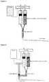
- FIG. 2A first such apparatus of the invention is shown in FIG. 2 and also in FIG. 3 , and a second in FIG. 4 ; these figures, however, should not be understood as imposing any limitation.
- sealantis presently always meant the mixture of two sealant components.
- the “first drive”may also consist of two drive units, to be controlled separately, of which the first is connected to the first and the second to the second of the two conveying devices (cf. FIG. 4 ). According to one preferred embodiment, however, the first drive consists of a single drive unit, which is connected to the two conveying devices.
- the “two containers for sealant components”may be reservoir containers, i.e., containers which can each be filled with a defined amount of sealant component and then closed (cf. FIG. 2 and FIG. 3 ).
- the “two containers for sealant components”may be open containers, i.e., containers which can each be filled continuously with a sealant component (cf. FIG. 4 ). In this way, an uninterrupted flow of sealant can be achieved (cf. FIG. 4 ).
- the “mixing unit”may be a static mixer, a dynamic mixer, or a combination of both.
- the first and/or second driveis a servo drive, and more preferably the first and the second drive is in each case a servo drive.
- the two conveying devicesare pistons, of which one each reaches into one of the containers, which in this case are reservoir containers, and is able to push out the corresponding sealant component.
- the two conveying devicesare pumps, which by generating a reduced pressure are able to draw the sealant components from their containers.
- Suitable for this purposein particular are eccentric screw pumps and also scoop piston pumps.
- said containersare open containers, which can each be filled continuously with a sealant component (cf. FIG. 4 ).
- the mixing unitis preferably a static mixer, more particularly a static mixing tube.
- the compensating containeris preferably a cartridge of plastic or a component that is easy to clean, and more preferably is a cartridge of plastic, more particularly one made of polyethylene (PE).
- PEpolyethylene
- the apparatusis a 2-component mixing and metering system of the kind produced, for example, by Hilger u. Kern (Mannheim, Germany). These systems allow the conveying, mixing, and metering of sealant consisting of 2 components from reservoir containers (cf. FIG. 2 and FIG. 3 ).
- the sealantmay also be a sealant of the kind which cures substantially only after irradiation with actinic radiation, more particularly with UV radiation.
- An advantage of a sealant of this kindis that its curing can be initiated in a controlled way with a trigger (SCOD: sealant curing on demand).
- the apparatus of the inventionmay for this purpose comprise an integrated source of actinic radiation, more particularly of UV radiation.
- the containers of the apparatus of the inventionare each filled with one sealant component (components A and B, or base compound and curative).
- the sealant componentsare then mixed in a mixing unit and the resultant sealant is applied to a component, by conveying the sealant components from the containers by means of the first drive.
- a metering rate below a critical value preset in the drive controlleris actualized by lowering the conveying rate of the sealant components from the containers to the critical value of the metering rate, and filling the compensating container with sealant by means of the second drive in such a way that the rate at which the compensating container is filled corresponds to the difference between the critical value and the actualized value of the metering rate.
- a metering rate of, for example, 1 volume unit of sealant/unit of timeis actualized by lowering the conveying rate of the sealant components from the containers to 3 volume units of sealant/unit of time, and filling the compensating container at a rate of 2 volume units of sealant/unit of time.
- FIG. 2shows the apparatus of the invention in the case of a metering rate above the critical value.
- the metering rateis lower than the critical value, as indicated by a reduction in the thickness of the sealant bead.
- the compensating volume of the compensating containeris in this case filled with sealant.
- the conveying of the sealant components from the containersis halted, and the sealant is conveyed from the compensating container by means of the second drive, preferably until the sealant in the compensating container is used up.
- the conveying of the sealant components from the containersmay continue to take place by means of the first drive, and at the same time the sealant may be conveyed from the compensating container by means of the second drive, until the sealant in the compensating container is used up.
- the present inventionrelates, moreover, to a component which has been sealed by means of the method of the invention, preferably a component with complicated geometry, as employed in aircraft and space vehicles.
Landscapes
- Chemical & Material Sciences (AREA)
- Chemical Kinetics & Catalysis (AREA)
- Physics & Mathematics (AREA)
- Fluid Mechanics (AREA)
- Application Of Or Painting With Fluid Materials (AREA)
- Coating Apparatus (AREA)
- Accessories For Mixers (AREA)
- Sealing Material Composition (AREA)
- Medical Preparation Storing Or Oral Administration Devices (AREA)
- Basic Packing Technique (AREA)
- Processing And Handling Of Plastics And Other Materials For Molding In General (AREA)
Abstract
Description
Claims (14)
Applications Claiming Priority (5)
| Application Number | Priority Date | Filing Date | Title |
|---|---|---|---|
| DE102016217429 | 2016-09-13 | ||
| DE102016217429.0 | 2016-09-13 | ||
| DE102016224655.0 | 2016-12-12 | ||
| DE102016224655 | 2016-12-12 | ||
| PCT/EP2017/072215WO2018050482A1 (en) | 2016-09-13 | 2017-09-05 | Device and method for dynamic metering of sealing compounds |
Publications (2)
| Publication Number | Publication Date |
|---|---|
| US20190232330A1 US20190232330A1 (en) | 2019-08-01 |
| US11059070B2true US11059070B2 (en) | 2021-07-13 |
Family
ID=59799376
Family Applications (1)
| Application Number | Title | Priority Date | Filing Date |
|---|---|---|---|
| US16/332,919Expired - Fee RelatedUS11059070B2 (en) | 2016-09-13 | 2017-09-05 | Device and method for dynamic metering of sealing compounds |
Country Status (7)
| Country | Link |
|---|---|
| US (1) | US11059070B2 (en) |
| EP (1) | EP3512640B1 (en) |
| JP (1) | JP6999676B2 (en) |
| CN (1) | CN109789436B (en) |
| BR (1) | BR112019003551B1 (en) |
| CA (1) | CA3036589A1 (en) |
| WO (1) | WO2018050482A1 (en) |
Families Citing this family (4)
| Publication number | Priority date | Publication date | Assignee | Title |
|---|---|---|---|---|
| JP2021520991A (en)* | 2018-04-12 | 2021-08-26 | ノードソン コーポレーションNordson Corporation | Systems and methods for dispensing multi-component materials |
| MX2022007588A (en) | 2019-12-19 | 2022-07-19 | Chemetall Gmbh | Polyurea coating systems as sealants for the exterior of fuel tanks. |
| US20230018655A1 (en) | 2019-12-19 | 2023-01-19 | Construction Research & Technology Gmbh | Polyurea coating systems for construction waterproofing |
| DE102020128115A1 (en)* | 2020-10-26 | 2022-04-28 | Dürr Systems Ag | Application device for preferably partially boosted application |
Citations (29)
| Publication number | Priority date | Publication date | Assignee | Title |
|---|---|---|---|---|
| US3224411A (en)* | 1961-09-18 | 1965-12-21 | Ford Motor Co | Apparatus for applying adhesive to a surface |
| US3390814A (en)* | 1965-09-24 | 1968-07-02 | Chem Dev Corp | Mixing device |
| US3401847A (en)* | 1967-04-03 | 1968-09-17 | Thermon Mfg Co | Pneumatically powered applicator |
| US3989228A (en)* | 1974-12-19 | 1976-11-02 | Products Research & Chemical Corporation | Mixing and dispensing apparatus |
| US4067479A (en)* | 1975-07-31 | 1978-01-10 | Products Research & Chemical Corporation | Two part material meter-mix dispenser apparatus |
| US4666430A (en)* | 1984-12-05 | 1987-05-19 | I-Flow Corporation | Infusion pump |
| US4957572A (en)* | 1988-06-17 | 1990-09-18 | Saint-Gobain Vitrage | Method and apparatus for the production of a bead of organic material intended to serve as a seal and insert in a multiple glazing |
| US4995540A (en)* | 1987-12-07 | 1991-02-26 | Laurence Colin | Unit dosage dispenser for dental impression materials |
| US5064098A (en)* | 1990-02-23 | 1991-11-12 | Physical Systems, Inc. | Dual component dispenser gun |
| US5080493A (en)* | 1990-02-22 | 1992-01-14 | Minnesota Mining And Manufacturing Company | Static mixing assembly |
| US5224629A (en)* | 1992-03-19 | 1993-07-06 | Hsich Rong Fuh | Control structure for a pneumatic sealant gun |
| US5478150A (en) | 1994-01-24 | 1995-12-26 | Wilhelm A. Keller | Device for the continuous monitoring of the correct proportioning and mixing of at least two fluids |
| US5816445A (en)* | 1996-01-25 | 1998-10-06 | Stainless Steel Coatings, Inc. | Method of and apparatus for controlled dispensing of two-part bonding, casting and similar fluids and the like |
| US5979794A (en)* | 1997-05-13 | 1999-11-09 | Ingersoll-Rand Company | Two-part stream dispensing for high viscosity materials |
| EP1000669A1 (en) | 1998-11-09 | 2000-05-17 | Wilhelm A. Keller | A system for the transfer of reactive resins components from a remote source to the point of application |
| US6126401A (en)* | 1998-08-12 | 2000-10-03 | Computer Graphics Systems Development Corporation | Hybrid electric/hydraulic drive system |
| US6234355B1 (en)* | 1997-08-07 | 2001-05-22 | Lenhardt Maschinenbau Gmbh | Machine for filling the edge joints of insulating glass panes with a sealing compound consisting of two constituents |
| US6543580B1 (en)* | 1999-03-25 | 2003-04-08 | Barmag Ag | Lubrication apparatus and method of applying a lubricant |
| US20030080152A1 (en)* | 2001-10-25 | 2003-05-01 | International Business Machines Corporation | Apparatus for dispensing a multiple-component substance from a multiple-barrel cartridge |
| US6726773B1 (en)* | 2000-06-30 | 2004-04-27 | Fanuc Robotics North America, Inc. | Integral pneumatic dispenser and method for controlling same |
| US6736291B1 (en)* | 1999-05-21 | 2004-05-18 | Matsushita Electric Industrial Co., Ltd. | Viscous material application apparatus |
| US6896152B2 (en)* | 2000-03-02 | 2005-05-24 | Graco Minnesota Inc. | Electronic plural component proportioner |
| US20060278658A1 (en)* | 2005-06-13 | 2006-12-14 | George Nisbet | Method and apparatus for metering a fluid mixture |
| US20070000947A1 (en)* | 2005-07-01 | 2007-01-04 | Lewis Russell H | Apparatus and methods for dispensing fluidic or viscous materials |
| US20090140007A1 (en)* | 2005-02-25 | 2009-06-04 | Voss Klaus-W | Device and method for blending a binder and a hardener component for producing a ready-made filler |
| EP2191904A2 (en) | 2008-12-01 | 2010-06-02 | Sturm Maschinenbau GmbH | Device and method for applying a multi-component mixture |
| US20110253747A1 (en) | 2008-12-18 | 2011-10-20 | Sika Technology Ag | Dispensing tool for multi-component substances |
| US8197122B2 (en)* | 2008-04-24 | 2012-06-12 | Tyco Healthcare Group Lp | Dynamic mixing applicator |
| WO2018019848A1 (en) | 2016-07-26 | 2018-02-01 | Chemetall Gmbh | Method and device for filling seal caps |
Family Cites Families (5)
| Publication number | Priority date | Publication date | Assignee | Title |
|---|---|---|---|---|
| DE4412261C2 (en)* | 1994-04-09 | 1996-10-17 | Jonas Konrad H | Device for merging at least two flow media |
| JPH0998560A (en)* | 1995-09-29 | 1997-04-08 | Zexel Corp | Brushless motor |
| FR2791648B1 (en)* | 1999-04-02 | 2001-05-25 | Oreal | PORTABLE DISPENSER FOR THE PACKAGING AND DISPENSING OF COLORED COSMETICS |
| JP2001149838A (en)* | 1999-11-30 | 2001-06-05 | Toyota Motor Corp | Apparatus for applying two-component mixed-curable sealing material and method for forming gasket in-situ |
| CN105385406B (en)* | 2015-12-08 | 2017-12-15 | 中国航空工业集团公司北京航空材料研究院 | A kind of room temperature vulcanization bi-component polysulfide ether sealant, its preparation and application |
- 2017
- 2017-09-05WOPCT/EP2017/072215patent/WO2018050482A1/ennot_activeCeased
- 2017-09-05CNCN201780055980.7Apatent/CN109789436B/ennot_activeExpired - Fee Related
- 2017-09-05JPJP2019535447Apatent/JP6999676B2/ennot_activeExpired - Fee Related
- 2017-09-05CACA3036589Apatent/CA3036589A1/enactivePending
- 2017-09-05EPEP17762112.5Apatent/EP3512640B1/enactiveActive
- 2017-09-05BRBR112019003551-6Apatent/BR112019003551B1/ennot_activeIP Right Cessation
- 2017-09-05USUS16/332,919patent/US11059070B2/ennot_activeExpired - Fee Related
Patent Citations (30)
| Publication number | Priority date | Publication date | Assignee | Title |
|---|---|---|---|---|
| US3224411A (en)* | 1961-09-18 | 1965-12-21 | Ford Motor Co | Apparatus for applying adhesive to a surface |
| US3390814A (en)* | 1965-09-24 | 1968-07-02 | Chem Dev Corp | Mixing device |
| US3401847A (en)* | 1967-04-03 | 1968-09-17 | Thermon Mfg Co | Pneumatically powered applicator |
| US3989228A (en)* | 1974-12-19 | 1976-11-02 | Products Research & Chemical Corporation | Mixing and dispensing apparatus |
| US4067479A (en)* | 1975-07-31 | 1978-01-10 | Products Research & Chemical Corporation | Two part material meter-mix dispenser apparatus |
| US4666430A (en)* | 1984-12-05 | 1987-05-19 | I-Flow Corporation | Infusion pump |
| US4995540A (en)* | 1987-12-07 | 1991-02-26 | Laurence Colin | Unit dosage dispenser for dental impression materials |
| US4957572A (en)* | 1988-06-17 | 1990-09-18 | Saint-Gobain Vitrage | Method and apparatus for the production of a bead of organic material intended to serve as a seal and insert in a multiple glazing |
| US5080493A (en)* | 1990-02-22 | 1992-01-14 | Minnesota Mining And Manufacturing Company | Static mixing assembly |
| US5064098A (en)* | 1990-02-23 | 1991-11-12 | Physical Systems, Inc. | Dual component dispenser gun |
| US5224629A (en)* | 1992-03-19 | 1993-07-06 | Hsich Rong Fuh | Control structure for a pneumatic sealant gun |
| US5478150A (en) | 1994-01-24 | 1995-12-26 | Wilhelm A. Keller | Device for the continuous monitoring of the correct proportioning and mixing of at least two fluids |
| US5816445A (en)* | 1996-01-25 | 1998-10-06 | Stainless Steel Coatings, Inc. | Method of and apparatus for controlled dispensing of two-part bonding, casting and similar fluids and the like |
| US5979794A (en)* | 1997-05-13 | 1999-11-09 | Ingersoll-Rand Company | Two-part stream dispensing for high viscosity materials |
| US6234355B1 (en)* | 1997-08-07 | 2001-05-22 | Lenhardt Maschinenbau Gmbh | Machine for filling the edge joints of insulating glass panes with a sealing compound consisting of two constituents |
| US6126401A (en)* | 1998-08-12 | 2000-10-03 | Computer Graphics Systems Development Corporation | Hybrid electric/hydraulic drive system |
| EP1000669A1 (en) | 1998-11-09 | 2000-05-17 | Wilhelm A. Keller | A system for the transfer of reactive resins components from a remote source to the point of application |
| US6260577B1 (en)* | 1998-11-09 | 2001-07-17 | Wilhelm A. Keller | System for the transfer of reactive resins components from a remote source to the point of application |
| US6543580B1 (en)* | 1999-03-25 | 2003-04-08 | Barmag Ag | Lubrication apparatus and method of applying a lubricant |
| US6736291B1 (en)* | 1999-05-21 | 2004-05-18 | Matsushita Electric Industrial Co., Ltd. | Viscous material application apparatus |
| US6896152B2 (en)* | 2000-03-02 | 2005-05-24 | Graco Minnesota Inc. | Electronic plural component proportioner |
| US6726773B1 (en)* | 2000-06-30 | 2004-04-27 | Fanuc Robotics North America, Inc. | Integral pneumatic dispenser and method for controlling same |
| US20030080152A1 (en)* | 2001-10-25 | 2003-05-01 | International Business Machines Corporation | Apparatus for dispensing a multiple-component substance from a multiple-barrel cartridge |
| US20090140007A1 (en)* | 2005-02-25 | 2009-06-04 | Voss Klaus-W | Device and method for blending a binder and a hardener component for producing a ready-made filler |
| US20060278658A1 (en)* | 2005-06-13 | 2006-12-14 | George Nisbet | Method and apparatus for metering a fluid mixture |
| US20070000947A1 (en)* | 2005-07-01 | 2007-01-04 | Lewis Russell H | Apparatus and methods for dispensing fluidic or viscous materials |
| US8197122B2 (en)* | 2008-04-24 | 2012-06-12 | Tyco Healthcare Group Lp | Dynamic mixing applicator |
| EP2191904A2 (en) | 2008-12-01 | 2010-06-02 | Sturm Maschinenbau GmbH | Device and method for applying a multi-component mixture |
| US20110253747A1 (en) | 2008-12-18 | 2011-10-20 | Sika Technology Ag | Dispensing tool for multi-component substances |
| WO2018019848A1 (en) | 2016-07-26 | 2018-02-01 | Chemetall Gmbh | Method and device for filling seal caps |
Non-Patent Citations (1)
| Title |
|---|
| International Search Report for International Application No. PCT/EP2017/072215, dated Aug. 12, 2017, 2 pages. |
Also Published As
| Publication number | Publication date |
|---|---|
| CN109789436B (en) | 2021-07-09 |
| EP3512640B1 (en) | 2022-03-16 |
| JP2019532813A (en) | 2019-11-14 |
| WO2018050482A1 (en) | 2018-03-22 |
| CN109789436A (en) | 2019-05-21 |
| BR112019003551B1 (en) | 2022-09-20 |
| US20190232330A1 (en) | 2019-08-01 |
| EP3512640A1 (en) | 2019-07-24 |
| JP6999676B2 (en) | 2022-02-04 |
| CA3036589A1 (en) | 2018-03-22 |
| BR112019003551A2 (en) | 2019-05-28 |
Similar Documents
| Publication | Publication Date | Title |
|---|---|---|
| US11059070B2 (en) | Device and method for dynamic metering of sealing compounds | |
| US5797520A (en) | Metering system and method for use with fluids having a high solid content | |
| CA2855303C (en) | Device for storing and mixing bone cement | |
| EP3102503B1 (en) | Cartridge and method for producing a cartridge | |
| CN102458785B (en) | Method and apparatus for preparing a paste compound for sealing insulating glass panes | |
| KR101271616B1 (en) | Two liquid glue dispenser device | |
| US20200246816A1 (en) | Fluid Dispensing System | |
| US20140224835A1 (en) | Dispensing tool for multi-component substances | |
| EP3086197A1 (en) | Machine for mixing and successively applying sealant material | |
| JP2001310143A (en) | Two-component mixed coating machine | |
| KR20100004454A (en) | Two liquide glue mixer dispenser device | |
| JP2005199272A (en) | Method for mixing paste-like multicomponent material in container and device for regulating filling state of the multicomponent material | |
| US11105779B2 (en) | Pressure system for liquid chromatography | |
| WO2021079194A3 (en) | Dispensing systems and methods including online remixing of thermal management and/or emi mitigation materials | |
| CN101529042A (en) | Method and apparatus for injecting a slurry material into a glass panel of an insulating glass sheet | |
| EP0709144A1 (en) | Device for the dosed distribution of a viscous mass, particularly of adhesive sealant for the manufacture of insulating glass units | |
| CN106362638A (en) | Glue mixing machine | |
| US6386398B2 (en) | Dispenser | |
| Grünfelder | Material Preparation for High-Precision Volumetric Dispensing | |
| TH2401005733A (en) | Dispenser system | |
| US20150225129A1 (en) | Multi-chamber squeeze tube | |
| JPH1119571A (en) | Device for pneumatically transporting liquid material | |
| JPH01199671A (en) | Multi-liquid type coating device for inside surface of pipe | |
| DE102013000801A1 (en) | Valve system for regular emptying of tank with liquid, controls post-flow of air during emptying of tank with liquid with drain valve, and synchronizes volume of inflowing air with volume of leakage mediums by electronic controller | |
| DE7013459U (en) | BARREL LINING. |
Legal Events
| Date | Code | Title | Description |
|---|---|---|---|
| AS | Assignment | Owner name:CHEMETALL GMBH, GERMANY Free format text:ASSIGNMENT OF ASSIGNORS INTEREST;ASSIGNOR:BUROCK, HEINZ;REEL/FRAME:048584/0193 Effective date:20190130 | |
| FEPP | Fee payment procedure | Free format text:ENTITY STATUS SET TO UNDISCOUNTED (ORIGINAL EVENT CODE: BIG.); ENTITY STATUS OF PATENT OWNER: LARGE ENTITY | |
| STPP | Information on status: patent application and granting procedure in general | Free format text:APPLICATION UNDERGOING PREEXAM PROCESSING | |
| STPP | Information on status: patent application and granting procedure in general | Free format text:APPLICATION DISPATCHED FROM PREEXAM, NOT YET DOCKETED | |
| STPP | Information on status: patent application and granting procedure in general | Free format text:DOCKETED NEW CASE - READY FOR EXAMINATION | |
| STPP | Information on status: patent application and granting procedure in general | Free format text:NON FINAL ACTION MAILED | |
| STPP | Information on status: patent application and granting procedure in general | Free format text:RESPONSE TO NON-FINAL OFFICE ACTION ENTERED AND FORWARDED TO EXAMINER | |
| STPP | Information on status: patent application and granting procedure in general | Free format text:NOTICE OF ALLOWANCE MAILED -- APPLICATION RECEIVED IN OFFICE OF PUBLICATIONS | |
| STPP | Information on status: patent application and granting procedure in general | Free format text:PUBLICATIONS -- ISSUE FEE PAYMENT RECEIVED | |
| STPP | Information on status: patent application and granting procedure in general | Free format text:PUBLICATIONS -- ISSUE FEE PAYMENT VERIFIED | |
| STCF | Information on status: patent grant | Free format text:PATENTED CASE | |
| FEPP | Fee payment procedure | Free format text:MAINTENANCE FEE REMINDER MAILED (ORIGINAL EVENT CODE: REM.); ENTITY STATUS OF PATENT OWNER: LARGE ENTITY | |
| LAPS | Lapse for failure to pay maintenance fees | Free format text:PATENT EXPIRED FOR FAILURE TO PAY MAINTENANCE FEES (ORIGINAL EVENT CODE: EXP.); ENTITY STATUS OF PATENT OWNER: LARGE ENTITY | |
| STCH | Information on status: patent discontinuation | Free format text:PATENT EXPIRED DUE TO NONPAYMENT OF MAINTENANCE FEES UNDER 37 CFR 1.362 | |
| FP | Lapsed due to failure to pay maintenance fee | Effective date:20250713 |