US11058892B2 - Revolving radiation collimator - Google Patents
Revolving radiation collimatorDownload PDFInfo
- Publication number
- US11058892B2 US11058892B2US15/971,861US201815971861AUS11058892B2US 11058892 B2US11058892 B2US 11058892B2US 201815971861 AUS201815971861 AUS 201815971861AUS 11058892 B2US11058892 B2US 11058892B2
- Authority
- US
- United States
- Prior art keywords
- collimator
- radiation
- channels
- wheel
- channel
- Prior art date
- Legal status (The legal status is an assumption and is not a legal conclusion. Google has not performed a legal analysis and makes no representation as to the accuracy of the status listed.)
- Active, expires
Links
Images


Classifications
- A—HUMAN NECESSITIES
- A61—MEDICAL OR VETERINARY SCIENCE; HYGIENE
- A61N—ELECTROTHERAPY; MAGNETOTHERAPY; RADIATION THERAPY; ULTRASOUND THERAPY
- A61N5/00—Radiation therapy
- A61N5/10—X-ray therapy; Gamma-ray therapy; Particle-irradiation therapy
- A61N5/1042—X-ray therapy; Gamma-ray therapy; Particle-irradiation therapy with spatial modulation of the radiation beam within the treatment head
- A—HUMAN NECESSITIES
- A61—MEDICAL OR VETERINARY SCIENCE; HYGIENE
- A61N—ELECTROTHERAPY; MAGNETOTHERAPY; RADIATION THERAPY; ULTRASOUND THERAPY
- A61N5/00—Radiation therapy
- A61N5/10—X-ray therapy; Gamma-ray therapy; Particle-irradiation therapy
- A61N5/1077—Beam delivery systems
- A61N5/1081—Rotating beam systems with a specific mechanical construction, e.g. gantries
- G—PHYSICS
- G01—MEASURING; TESTING
- G01B—MEASURING LENGTH, THICKNESS OR SIMILAR LINEAR DIMENSIONS; MEASURING ANGLES; MEASURING AREAS; MEASURING IRREGULARITIES OF SURFACES OR CONTOURS
- G01B11/00—Measuring arrangements characterised by the use of optical techniques
- G01B11/26—Measuring arrangements characterised by the use of optical techniques for measuring angles or tapers; for testing the alignment of axes
- G01B11/27—Measuring arrangements characterised by the use of optical techniques for measuring angles or tapers; for testing the alignment of axes for testing the alignment of axes
- G—PHYSICS
- G21—NUCLEAR PHYSICS; NUCLEAR ENGINEERING
- G21K—TECHNIQUES FOR HANDLING PARTICLES OR IONISING RADIATION NOT OTHERWISE PROVIDED FOR; IRRADIATION DEVICES; GAMMA RAY OR X-RAY MICROSCOPES
- G21K1/00—Arrangements for handling particles or ionising radiation, e.g. focusing or moderating
- G21K1/02—Arrangements for handling particles or ionising radiation, e.g. focusing or moderating using diaphragms, collimators
- G21K1/025—Arrangements for handling particles or ionising radiation, e.g. focusing or moderating using diaphragms, collimators using multiple collimators, e.g. Bucky screens; other devices for eliminating undesired or dispersed radiation
- G—PHYSICS
- G21—NUCLEAR PHYSICS; NUCLEAR ENGINEERING
- G21K—TECHNIQUES FOR HANDLING PARTICLES OR IONISING RADIATION NOT OTHERWISE PROVIDED FOR; IRRADIATION DEVICES; GAMMA RAY OR X-RAY MICROSCOPES
- G21K1/00—Arrangements for handling particles or ionising radiation, e.g. focusing or moderating
- G21K1/02—Arrangements for handling particles or ionising radiation, e.g. focusing or moderating using diaphragms, collimators
- G21K1/04—Arrangements for handling particles or ionising radiation, e.g. focusing or moderating using diaphragms, collimators using variable diaphragms, shutters, choppers
- G21K1/046—Arrangements for handling particles or ionising radiation, e.g. focusing or moderating using diaphragms, collimators using variable diaphragms, shutters, choppers varying the contour of the field, e.g. multileaf collimators
- A—HUMAN NECESSITIES
- A61—MEDICAL OR VETERINARY SCIENCE; HYGIENE
- A61N—ELECTROTHERAPY; MAGNETOTHERAPY; RADIATION THERAPY; ULTRASOUND THERAPY
- A61N5/00—Radiation therapy
- A61N5/10—X-ray therapy; Gamma-ray therapy; Particle-irradiation therapy
- A61N2005/1092—Details
- A61N2005/1095—Elements inserted into the radiation path within the system, e.g. filters or wedges
Definitions
- the overarching goal of the collimator systemis to deliver a beam of radiation produced by a source (for example a LINAC) to a target (for example a tumor in a patient's brain).
- a sourcefor example a LINAC
- a targetfor example a tumor in a patient's brain.
- a collimatoris used.
- a collimatoris generally a piece of dense radiopaque metal that substantially blocks a beam of radiation except where a formed or machined hole allows the radiation to be transmitted through.
- a larger radiation footprintmay be produced by the radiation source (for example a LINAC or cobalt), but only those particles aligned to pass through the collimator will be permitted through to reach the target, the excess being absorbed or scattered internally.
- the radiation sourcefor example a LINAC or cobalt
- another pre-existing typeis a “multi leaf collimator” using multiple thin tungsten plates moving in and out of the beam path to generate the desired beam exposure shape during treatment. This complex mechanism is complex, bulky, expensive, and prone to mechanical failure.
- the inventionrelates to the field of radiation therapy, and in particular, to collimator systems and associated methods of controlling the size and shape of radiation treatment beams during radiation therapy.
- the inventionpertains to a radiation collimator assembly that includes a rotatable collimator body or collimator wheel having multiple collimator channels defined therein.
- the collimator channelsextend longitudinally perpendicular to the rotational axis of the collimator wheel, extending from the perimeter of the wheel, passing through the center and out to the opposite perimeter of the wheel.
- the collimator wheelis at least partly surrounded by a collimator shield, excepting at least the portion having the selected collimator channel that is aligned with the radiation source and the patient target to allow passage of the radiation beam therethrough.
- the posterior, LINAC-facing portion of the collimator wheelis ensheathed in shielding to prevent stray radiation from passing through non-selected collimator channels.
- the collimator shieldis fabricated from a suitable radiation absorptive material, typically tungsten or tungsten alloy, so as to block and absorb any scattered radiation emitted from orifices of non-aligned channels.
- the collimator bodyis motorized and precisely indexed for rapid and exacting computer-controlled positioning of the selected collimator channel geometry with the radiation source, thereby delivering a desired beam shape to the precise dimensions required at the target.
- a revolving collimator wheelBy using a revolving collimator wheel, multiple sizes of the beam may be utilized during one treatment, quickly and automatically switching between two or more selected collimators.
- collimation assemblieshave the advantage of being rapidly changeable by computer control, while remaining small, reliable in their simplicity and low in cost. Moreover, such assemblies can utilize a single motor to switch between select one or more collimator channels.
- the aspects of the invention described hereinallow for a more reliable radiation collimator that can quickly and precisely change X-ray exposure from 1 mm to 30 mm diameter at isocenter, and can function more reliably than many prior art collimators.
- Such collimator assembliesenable rapid, automated (motorized and computer controlled) changing of beam aperture in the service of therapeutic radiation delivery, for example to treat brain tumors.
- collimator systems described hereinallow for beam collimation without requiring use of a conventional block collimator and/or multi-leaf collimator system, such as those commonly used in conventional radiation treatment systems, which are bulky and prone to mechanical malfunction over time.
- an exemplary radiation collimator assemblyincludes a radiation source and a collimator wheel rotatable about a rotational axis thereof.
- the collimator wheelhas multiple collimator channels that include a first and second collimator channel defined within the collimator wheel that are arranged substantially perpendicular to the rotational axis of the collimator wheel.
- the collimatorcan include additional channels, for example three or more channels.
- the collimatorcan include any number of channels desired (e.g. 2, 3, 4, 5, 6, 7, 8, 9, 10 channels or more).
- each of the first and second collimator channelspass through a center of the collimator wheel through which the rotational axis extends.
- at least some of the collimator channelsare of differing sizes and/or shapes.
- the multiple collimator channelsare distributed at regular intervals along the collimator wheel.
- the first and second collimator channelsare selectable by rotationally moving the collimator wheel to align one of the first and second collimator channels with the radiation source. Selective rotation of the collimator wheel can be facilitated by a motor and control unit operably coupled to the wheel.
- the collimator assemblyincludes a motor operably coupled with the collimator wheel so as to rotate the collimator wheel about the rotational axis; and a control unit operably coupled with the motor to control rotation of the collimator wheel to a collimator position corresponding to alignment of a selected collimator channel with the radiation source.
- the control unitis communicatively coupled with one or more sensors configured to detect the collimator position.
- the one or more sensorscan include one or more encoder readers and the collimator wheel includes multiple markers positioned thereon so that detection of a marker corresponds to alignment of a corresponding collimator channel.
- An exemplary treatment systemcan include a radiation collimator assembly, such as described above, that is configured to deliver a radiation beam from a radiation source through one or more selected collimator channels of the collimator wheel to a target within a patient.
- a radiation collimator assemblysuch as described above
- Such a systemcan include a motor operably coupled with the collimator wheel so as to rotate the collimator wheel about the rotational axis and a control unit operably coupled with the motor to control rotation of the collimator wheel to positions corresponding to alignment of one or more selected collimator channel with the radiation source.
- the control unitis configured rotate the collimator wheel to align one or more selected collimator channels with the radiation source, the one or more selected collimator channels corresponding to one or more desired therapy beams.
- the treatment systemincludes a collimator shield.
- the collimator shieldcan be configured to surround at least a portion of the collimator body during delivery of therapy so as to block radiation from non-aligned collimator channels while allowing passage of a therapy beam from the selected, aligned collimator channel.
- the collimator shieldsubstantially surrounds a portion of the collimator wheel facing the radiation source except for the entry orifice of the selected, aligned collimator channel.
- the collimator shieldsubstantially surrounds the collimator body except for an aperture at an apex of the shield through which includes the exit orifice of the selected aligned collimator channel is exposed as well as a passage at the inlet orifice of the aligned channel to allow entry of the radiation beam through the selected channel. While a conically shaped shield is depicted in the embodiments presented herein, it is appreciated that the collimator shield could be formed in various different shapes so long as the shield allows radiation to pass through the selected, aligned channel while blocking radiation emitted from non-selected channels and from around the shield itself, resulting in minimal radiation leakage around the intended beam.
- the treatment systemcan include an alignment verification mechanism.
- a verification featurecan include an optical alignment feature, such as an optical laser light mechanism that directs a laser light beam through the selected collimator channel and detects the laser light beam emanating from an exit orifice.
- the treatment systemfurther includes one or more imaging devices for monitoring a patient during treatment.
- the collimatorincludes a collimator body having a pivot feature about which the collimator body is rotatable about a pivotal axis and multiple collimator channels extending through the collimator body, each being substantially perpendicular to the pivotal axis about which the collimator body is revolved. In some embodiments, each of the multiple collimator channels intersects the pivotal axis.
- An exemplary methodincludes selecting a first collimator channel from multiple collimator channels in a collimator body, the selected first collimator channel corresponding to a desired first therapy beam.
- the collimator bodyis rotatable within the treatment system along a rotational axis of the collimator body and the multiple collimator channels differ in size and/or shape and extend substantially perpendicular to the rotational axis.
- the collimator bodyis rotated along the rotational axis until the selected first collimator channel is aligned with the radiation source, then a first particle beam is transmitted from a radiation source through the selected first collimator channel so as to direct the desired first therapy beam to the target within the patient.
- Such methodscan further include selecting a second collimator channel in the collimator body, the selected second collimator channel corresponding to a desired second therapy beam differing from the first therapy beam in size and/or shape.
- the collimator bodyis then rotated along the rotational axis until the selected second collimator channel is aligned with the radiation source and then a second particle beam is transmitted from the radiation source through the selected second collimator channel so as to direct the desired second therapy beam to the target within the patient.
- rotating the collimator body until the selected first collimator channel is alignedcomprises rotating the collimator body until a sensor of a control unit of the system detects a marker disposed on the collimator body indicating a collimator position that corresponds to alignment of the first collimator channel.
- Such methodscan further include validating alignment of the first collimator channel with the radiation source by transmitting a laser light beam through the collimator channel and detecting the laser light beam emitted from an exit aperture of the first collimator channel.
- FIG. 1shows a cross section of an example revolving collimator wheel having collimator channels passing therethrough.
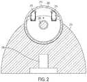
- FIG. 2shows an example revolving collimator wheel mounted upon a conical shield, the collimator wheel having magnetic encoder trackers that sense when the wheel has been brought into a desired collimator position.
- FIG. 3shows the apex of an example conical shield, including the exit openings of the collimator channels of the collimator wheel and cameras for monitoring the patient.
- FIG. 4shows an example collimator wheel and associated motor configured to drive between positions, and a linear accelerator that passes radiation through the collimator wheel and associated features.
- FIG. 5shows another example conical shield surrounding a periphery of the collimator wheel to cover orifices of non-aligned channels.
- the inventionrelates generally to radiation treatment systems and methods of use, in particular collimator systems provide selective control and delivery of collimated beams of radiation.
- FIG. 1shows a cross sectional view of a revolving collimator wheel 100 having collimator channels 140 passing therethrough.
- Collimator wheel 100has longitudinally extending channels or collimator channels 105 , 115 and 125 defined therein, for example machined through the body of collimator wheel 100 .
- the figureshows multiple other channels that are not labeled for the sake of clarity of the drawing.
- the collimator channelsmay be of various sizes, diameters or shapes. In some embodiments, each collimator channel is of a different diameter. For example, as shown in FIG. 1 , collimator channel 105 is of larger bore than collimator channel 115 , which is of larger bore than collimator channel 125 .
- Each collimator channelextends from a radiation entrance aperture 106 to an exit aperture 107 .
- the size of the entrance aperture 106is smaller than that of the exit aperture 107 to facilitate a sharp falloff of radiation dose at the margins of the irradiated area.
- the collimator wheel 100is rotated so that a selected collimator channel is aligned with a radiation source 110 to allow passage of a particle radiation beam 111 through the selected channel, thereby providing a desired therapy beam to a target 112 in the patient.
- the entrance and exit apertures 150are visible about the circumference collimator wheel 100 turns on axis 101 .
- collimator wheel 100couples with a 50 : 1 reduction gearbox and electric motor.
- channel 105 and exit aperture 107are round.
- the channelsmay be of any size or shape, for example square.
- Collimator wheel 100can be formed of any suitable material, for example machined from a titanium alloy. While collimator wheel 100 is shown as being oriented vertically relative to the surface on which the patient rests, it is appreciated that the collimator wheel 100 could be configured in any orientation so long as the treatment beams passing through the collimator channels are directed to the target. Further, while the collimator wheel is shown as having eight collimator channels it is appreciated that such collimator wheels could include more or fewer collimator channels.
- FIG. 2shows a cross section of a revolving collimator wheel 200 mounted upon a collimator shield 210 , and rotating between collimator positions on axis 205 .
- the collimator shield 210substantially ensheaths the portion of the collimator wheel facing the radiation source so as to prevent radiation from entering non-aligned collimator channels, and of a thickness designed to otherwise provide shielding against leakage for the radiation source.
- the rotational position of the collimator wheelcan be precisely controlled by a control system by use of one or more sensors or encoders that monitor the position of the collimator wheel 200 , for example by detecting markers disposed on the periphery of the collimator wheel.
- the position of the collimator wheelis precisely monitored by encoder reader heads 215 and 216 , which track a thin tape-like encoder strip affixed to the inner rim 214 of collimator wheel 100 , adjacent to the path of reader heads 215 and 216 .
- the control systemdetects signals produced by precisely placed changes in the electromagnetic interaction between the encoders and the encoder strip. Using this combination of encoder strip affixed to internal rim 214 and encoder reader heads, the control system senses when the wheel has been brought into the desired collimator position.
- a LINAC head 230is also shown in the cross section of collimator shield 210 , which is the source of the radiation delivered to the entrance aperture of a selected collimator.
- an ion chamber for measuring radiation intensityis included in the collimator shield between the LINAC head 230 and collimator wheel 200 .
- Alternative positional encoder schemescould include mechanical stops such as gear teeth and divots, and/or optically sensed position markers.
- FIG. 3shows the apex of the conical shield, including the exit openings of the collimator channels and cameras for monitoring the patient.
- Collimator wheel 300is visible edge-on, including selected channel exit aperture 305 and other apertures that are not identified and thus not aligned with the LINAC (underlying and not visible).
- Motor 315turns collimator wheel 305 to a selected position in which the desired aperture is aligned with the LINAC.
- the systemincludes one or more cameras to, for example cameras 310 , positioned to permit the patient to be monitored while undergoing radiation treatment.
- Encoder interpretation computer subsystem 320receives signals from encoder reader heads (see FIG.
- motor control computer subsystem 330serves to activate motor 315 until encoders indicate that the selected collimator is aligned with the LINAC.
- the systemis configured to change the collimator wheel position between multiple positions associated with select collimator channels during therapy so as to differing sizes of treatment beams to the target.
- FIG. 4shows a cross-sectional view of the collimator wheel in the context of the motor that drives between positions and a linear accelerator that passes radiation through an aligned collimator channel and associated features.
- collimator wheel 449has selected and aligned channel 451 with exit aperture 452 and entrance aperture 450 .
- Collimator shield 410surrounds the collimator wheel 449 along the portion facing the radiation source to allow passage of the particle beam through the inlet and exit orifices of channel 451 while preventing radiation from entering non-aligned channels.
- collimator wheel 449is selectively turned into the desired position via shaft 453 with bushing 434 , shaft 453 being connected with gearbox 444 via coupling bracket and base 420 .
- Gearbox 44is coupled to and driven by motor 445 , and provides a reduction in revolutions at a pre-defined ratio, permitting very fine control of the degree to which the collimator wheel is turned and aligned with the radiation source, the LINAC head 460 and distal margin of LINAC body 461 .
- the pre-defined ratiocan be 10:1, 20:1, 30:1, 40:1, 50:1, 60:1, 70:1, 80:1, 90:1 or any ratio suitable for a given geometry of the collimator wheel and treatment system and desired resolution of adjustment.
- energy exiting LINAC head 460enters sealed ion chamber 403 which permits monitoring of dose, dose rate and field symmetry by virtue of the fact that radiation that enters the ion chamber will produce a measureable ionization current that is proportional to the x-ray beam intensity.
- the systemincludes laser shield mount holding laser 416 , the beam from which is bent at a right angle by mirror 415 and directed into diaphragm iris lens 419 after which the laser light passes through shield bore 421 defined in shield 410 to reach the beam path right angle optical mirror 422 . Because the beam path right angle optical mirror 422 is reflective to light but transparent to radiation, a properly aligned collimator can be detected by a laser beam being emitted from exit aperture 452 of collimator 451 , while maintaining functionality of the primary radiation delivery alignment, a function useful in initial validation and verification of each machine.
- FIG. 5shows another example system with the same or similar collimator wheel and associated components shown in FIG. 1 and a conical collimator shield 510 that substantially surrounds the periphery of the collimator wheel so as to block and absorb radiation emitted from orifices of non-aligned collimator channels while allowing passage of a particle beam 111 from the radiation source 110 through the selected, aligned collimator channel to provide a desired therapy beam to the target 112 .
- the collimator shield 510covers any orifices of non-aligned channels, and its resulting greater thickness minimizes radiation leakage from linear accelerator 110 .
- the shieldcan cover less than all orifices of non-aligned channels.
- the shieldcan include multiple shield components to cover orifices of non-aligned channels and is not required to be a unitary component.
- Various configurations of the shieldcan be realized in accordance with the concepts described herein.
Landscapes
- Health & Medical Sciences (AREA)
- Engineering & Computer Science (AREA)
- Physics & Mathematics (AREA)
- Biomedical Technology (AREA)
- General Health & Medical Sciences (AREA)
- Radiology & Medical Imaging (AREA)
- Life Sciences & Earth Sciences (AREA)
- Animal Behavior & Ethology (AREA)
- Nuclear Medicine, Radiotherapy & Molecular Imaging (AREA)
- Public Health (AREA)
- Veterinary Medicine (AREA)
- Pathology (AREA)
- Spectroscopy & Molecular Physics (AREA)
- General Engineering & Computer Science (AREA)
- High Energy & Nuclear Physics (AREA)
- General Physics & Mathematics (AREA)
- Radiation-Therapy Devices (AREA)
Abstract
Description
Claims (20)
Priority Applications (2)
| Application Number | Priority Date | Filing Date | Title |
|---|---|---|---|
| US15/971,861US11058892B2 (en) | 2017-05-05 | 2018-05-04 | Revolving radiation collimator |
| US17/313,453US11826582B2 (en) | 2017-05-05 | 2021-05-06 | Revolving radiation collimator |
Applications Claiming Priority (5)
| Application Number | Priority Date | Filing Date | Title |
|---|---|---|---|
| US201762502472P | 2017-05-05 | 2017-05-05 | |
| USPCTUS2017038256 | 2017-06-20 | ||
| PCT/US2017/038256WO2018203918A1 (en) | 2017-05-05 | 2017-06-20 | Revolving radiation collimator |
| WOPCT/US2017/038256 | 2017-06-20 | ||
| US15/971,861US11058892B2 (en) | 2017-05-05 | 2018-05-04 | Revolving radiation collimator |
Related Child Applications (1)
| Application Number | Title | Priority Date | Filing Date |
|---|---|---|---|
| US17/313,453ContinuationUS11826582B2 (en) | 2017-05-05 | 2021-05-06 | Revolving radiation collimator |
Publications (2)
| Publication Number | Publication Date |
|---|---|
| US20180318607A1 US20180318607A1 (en) | 2018-11-08 |
| US11058892B2true US11058892B2 (en) | 2021-07-13 |
Family
ID=64014028
Family Applications (2)
| Application Number | Title | Priority Date | Filing Date |
|---|---|---|---|
| US15/971,861Active2039-05-20US11058892B2 (en) | 2017-05-05 | 2018-05-04 | Revolving radiation collimator |
| US17/313,453Active2038-09-14US11826582B2 (en) | 2017-05-05 | 2021-05-06 | Revolving radiation collimator |
Family Applications After (1)
| Application Number | Title | Priority Date | Filing Date |
|---|---|---|---|
| US17/313,453Active2038-09-14US11826582B2 (en) | 2017-05-05 | 2021-05-06 | Revolving radiation collimator |
Country Status (1)
| Country | Link |
|---|---|
| US (2) | US11058892B2 (en) |
Cited By (3)
| Publication number | Priority date | Publication date | Assignee | Title |
|---|---|---|---|---|
| US20210196987A1 (en)* | 2018-08-24 | 2021-07-01 | Our United Corporation | Radiotherapy device, control driving method thereof, and radiotherapy system |
| US11844637B2 (en) | 2017-09-06 | 2023-12-19 | Zap Surgical Systems, Inc. | Therapeutic radiation beam detector for radiation treatment systems |
| US12246192B2 (en) | 2021-02-01 | 2025-03-11 | Zap Surgical Systems, Inc. | Inverse planning device and methods for radiation treatment |
Families Citing this family (8)
| Publication number | Priority date | Publication date | Assignee | Title |
|---|---|---|---|---|
| US11058892B2 (en) | 2017-05-05 | 2021-07-13 | Zap Surgical Systems, Inc. | Revolving radiation collimator |
| CN108379748B (en)* | 2018-04-09 | 2019-11-05 | 西安大医集团有限公司 | Radiotherapy head and radiotherapy unit |
| US11684446B2 (en) | 2019-02-27 | 2023-06-27 | Zap Surgical Systems, Inc. | Device for radiosurgical treatment of uterine fibroids |
| CN114177542B (en)* | 2020-09-15 | 2024-06-11 | 西安大医集团股份有限公司 | Dose control method, device, controller and system in radiotherapy |
| CN114452549B (en)* | 2022-01-17 | 2023-01-24 | 江苏瑞尔医疗科技有限公司 | Collimation system capable of realizing automatic and quick switching |
| WO2024076920A2 (en)* | 2022-10-03 | 2024-04-11 | Tae Life Sciences, Llc | Systems, devices, and methods for variable collimation of a neutron beam |
| US20240315566A1 (en)* | 2023-03-20 | 2024-09-26 | Izotropic Corporation | Optical system for breast x-ray computed tomography |
| WO2025072538A1 (en)* | 2023-09-29 | 2025-04-03 | Tae Life Sciences, Llc | Neutron capture therapy (nct) treatment planning and delivery |
Citations (39)
| Publication number | Priority date | Publication date | Assignee | Title |
|---|---|---|---|---|
| NL7215879A (en) | 1971-11-23 | 1973-05-25 | ||
| US4266135A (en) | 1977-07-01 | 1981-05-05 | Ohio Nuclear, Inc. | Method of determining collimator aperture efficiency and apparatus with an efficient collimator aperture size |
| JPS6082300U (en) | 1983-11-09 | 1985-06-07 | 株式会社日立メデイコ | X-ray composite collimator |
| US5054041A (en) | 1990-03-19 | 1991-10-01 | General Electric Company | High precision x-ray collimator |
| JPH0767975B2 (en) | 1992-05-29 | 1995-07-26 | 西部電機株式会社 | How to stow goods |
| DE19728788A1 (en) | 1997-07-05 | 1999-01-07 | Nis Peter Boysen | Position control of medical treatment table |
| US5945684A (en) | 1997-09-05 | 1999-08-31 | Medical University Of South Carolina Foundation Of Research Development | Computer controlled collimator changer |
| CN1481756A (en) | 2002-08-14 | 2004-03-17 | ��ʽ���綫֥ | Concentrated radiation therapy equipment |
| US20040066889A1 (en)* | 2002-06-10 | 2004-04-08 | Swift Roderick D. | Collimator aperture scheduling for enhanced pencil-beam resolution |
| US20040251419A1 (en) | 2003-06-16 | 2004-12-16 | Nelson Robert Sigurd | Device and system for enhanced SPECT, PET, and Compton scatter imaging in nuclear medicine |
| CN1666301A (en) | 2002-07-05 | 2005-09-07 | 埃莱克塔公共有限公司 | Apparatus and method for focusing a radiotherapy field, where slidable plates on the collimator ring controls the collimator |
| US20050236588A1 (en) | 2004-04-21 | 2005-10-27 | Moshe Ein-Gal | Radiation shield capsule |
| US20060245548A1 (en)* | 2005-04-22 | 2006-11-02 | Joseph Callerame | X-ray backscatter inspection with coincident optical beam |
| US20080212738A1 (en)* | 2006-12-13 | 2008-09-04 | Oraya Therapeutics, Inc. | Orthovoltage radiotherapy |
| US20090086909A1 (en) | 2005-08-25 | 2009-04-02 | Shenzhen Hyper Technology Incorporation | Radiotherapy Device |
| US20090103686A1 (en)* | 2007-10-23 | 2009-04-23 | American Science And Engineering, Inc. | X-Ray Imaging with Continuously Variable Zoom and Lateral Relative Displacement of the Source |
| US20090110146A1 (en) | 2007-10-28 | 2009-04-30 | Orbital Therapy Llc | Highly shielded radiation therapy system |
| US20100094119A1 (en)* | 2007-02-28 | 2010-04-15 | University Of Maryland, Baltimore | Method and equipment for image-guided stereotactic radiosurgery of breast cancer |
| US20100237259A1 (en) | 2009-03-23 | 2010-09-23 | Chao Wang | Method and device for image guided dynamic radiation treatment of prostate cancer and other pelvic lesions |
| US8139714B1 (en) | 2009-06-25 | 2012-03-20 | Velayudhan Sahadevan | Few seconds beam on time, breathing synchronized image guided all fields simultaneous radiation therapy combined with hyperthermia |
| WO2012040964A1 (en) | 2010-09-30 | 2012-04-05 | 上海世鹏实验室科技发展有限公司 | Radiotherapy device, radiation device and collimation device |
| US20130136239A1 (en) | 2011-11-25 | 2013-05-30 | Aribex, Inc. | Apparatus & methods for collimation of x-rays |
| US20130188856A1 (en) | 2011-12-01 | 2013-07-25 | Varian Medical Systems, Inc. | Systems and methods for real-time target validation for image-guided radiation therapy |
| US20130261430A1 (en) | 2010-12-13 | 2013-10-03 | Koninklijke Philips Electronics N.V. | Therapeutic apparatus comprising a radiotherapy apparatus, a mechanical positioning system, and a magnetic resonance imaging system |
| WO2013180883A1 (en) | 2012-05-30 | 2013-12-05 | Indiana University Research And Technology Corporation | Revolving collimator for proton stereotactic body radiotherapy |
| US20140140471A1 (en) | 2012-11-16 | 2014-05-22 | Neurologica Corp. | Computerized tomography (ct) imaging system with multi-slit rotatable collimator |
| US9014341B2 (en) | 2012-11-27 | 2015-04-21 | Ge Medical Systems Global Technology Company Llc | CT collimator and CT system including the CT collimator |
| WO2015096572A1 (en)* | 2013-12-25 | 2015-07-02 | 深圳市奥沃医学新技术发展有限公司 | Radiotherapy equipment and laser verification device therefor |
| US20160095558A1 (en) | 2014-04-16 | 2016-04-07 | Board Of Regents, The University Of Texas System | Radiation therapy systems that include primary radiation shielding, and modular secondary radiation shields |
| US9308395B2 (en) | 2011-12-02 | 2016-04-12 | Varian Medical Systems, Inc. | Radiation systems with minimal or no shielding requirement on building |
| US20160317839A1 (en) | 2008-07-21 | 2016-11-03 | Varian Medical Systems, Inc. | External beam radiotherapy and imaging with radioactive isotope |
| WO2017020244A1 (en) | 2015-08-04 | 2017-02-09 | 西安大医数码技术有限公司 | Focussed radiotherapy apparatus and radiation therapy device |
| WO2017041750A1 (en) | 2015-09-10 | 2017-03-16 | Shanghai United Imaging Healthcare Co., Ltd. | Multi-leaf collimator and driving system |
| CN106512221A (en) | 2015-09-14 | 2017-03-22 | 上海联影医疗科技有限公司 | Multi-leaf collimator, driving system of blades of multi-leaf collimator and driving method |
| US9604077B2 (en) | 2014-06-16 | 2017-03-28 | The Board Of Trustees Of The Leland Stanford Junior University | Visualizing radiation therapy beam in real-time in the context of patient's anatomy |
| WO2017100611A1 (en) | 2015-12-09 | 2017-06-15 | ETM Electromatic, Inc. | Self-shielded image guided radiation oncology system |
| WO2018203918A1 (en) | 2017-05-05 | 2018-11-08 | Zap Surgical Systems, Inc. | Revolving radiation collimator |
| US20180318607A1 (en) | 2017-05-05 | 2018-11-08 | Zap Surgical Systems, Inc. | Revolving radiation collimator |
| US20200038685A1 (en)* | 2015-06-13 | 2020-02-06 | Saskatchewan Cancer Agency | Mini-beam collimators for medical linear accelerators |
Family Cites Families (133)
| Publication number | Priority date | Publication date | Assignee | Title |
|---|---|---|---|---|
| US2595260A (en) | 1949-02-05 | 1952-05-06 | F R Machine Works | Multiplane X-ray apparatus |
| DE1033844B (en) | 1951-09-04 | 1958-07-10 | Ialicenciaia Talalmanyokat Ert | X-ray apparatus for exercise radiation |
| US2781454A (en) | 1952-12-04 | 1957-02-12 | Ca Atomic Energy Ltd | Rotational therapy unit |
| US2818510A (en) | 1953-07-23 | 1957-12-31 | Philips Corp | Diagnostic x-ray device |
| US3082322A (en) | 1958-11-28 | 1963-03-19 | Westinghouse Electric Corp | Therapy unit |
| US3349242A (en) | 1964-08-07 | 1967-10-24 | Carl B Braestrup | Apparatus for radiation therapy of diseased tissues with minimum exposure to healthy tissues |
| DE1516422A1 (en) | 1965-03-27 | 1969-08-07 | Setaelae Kai Martin Edvard | Equipment for radiation treatment including the execution of the related measurements |
| US3488495A (en) | 1965-10-20 | 1970-01-06 | Justin G Schneeman | Radiation protective enclosure having a door which pivots into the enclosure |
| US3281598A (en) | 1965-11-19 | 1966-10-25 | Picker X Ray Corp Waite Mfg | Overhead support for a vertically and rotatably movable x-ray tube support arm and cooperating tiltable x-ray table |
| FR1454127A (en) | 1966-02-04 | 1966-07-22 | Artashes Ervandovich Atovmian | Device for remote irradiation therapy |
| US3588499A (en) | 1967-06-15 | 1971-06-28 | Ca Atomic Energy Ltd | Radiation therapy machine with a rotatable hypesbaric chamber having a radiation source mounted therein |
| FR2054492B1 (en) | 1969-07-16 | 1974-06-14 | Radiologie Cie Gle | |
| US3617749A (en) | 1970-01-12 | 1971-11-02 | Philips Corp | Column support for x-ray apparatus |
| DE2134122C3 (en) | 1971-07-08 | 1984-05-30 | Siemens AG, 1000 Berlin und 8000 München | X-ray machine for skull examinations |
| US3833813A (en) | 1972-09-25 | 1974-09-03 | Philips Corp | Device for examining a patient, in particular by means of x-rays |
| JPS5222553B2 (en) | 1973-02-20 | 1977-06-17 | ||
| US3892967A (en) | 1973-12-10 | 1975-07-01 | Measurex Corp | Apparatus for radiological examination of a subject through a solid angle |
| US4177382A (en) | 1976-04-28 | 1979-12-04 | E M I Limited | Radiography |
| GB1584953A (en) | 1976-07-28 | 1981-02-18 | Emi Ltd | Radiography |
| US4209706A (en) | 1976-11-26 | 1980-06-24 | Varian Associates, Inc. | Fluoroscopic apparatus mounting fixture |
| US4288700A (en) | 1979-10-22 | 1981-09-08 | General Electric Company | Cable handling device for diagnostic x-ray apparatus |
| US4338521A (en) | 1980-05-09 | 1982-07-06 | General Electric Company | Modular radiation detector array and module |
| US4363128A (en) | 1980-09-29 | 1982-12-07 | John K. Grady | X-Ray drive apparatus |
| US4358856A (en) | 1980-10-31 | 1982-11-09 | General Electric Company | Multiaxial x-ray apparatus |
| US4339825A (en) | 1980-10-31 | 1982-07-13 | General Electric Company | Bi-plane angiographic apparatus |
| NL8102286A (en) | 1981-05-11 | 1981-07-01 | Philips Nv | MEDICAL DEVICE. |
| DE3321057A1 (en) | 1983-06-09 | 1984-12-13 | Philipp 8500 Nürnberg Röder | Device for the examination or treatment of a patient with penetrating radiation |
| US4541108A (en) | 1984-01-30 | 1985-09-10 | John K. Grady | X-Ray apparatus with tilting table |
| US4649560A (en) | 1984-01-30 | 1987-03-10 | John K. Grady | Digital X-ray stand |
| US4560882A (en) | 1984-08-31 | 1985-12-24 | Regents Of The University Of California | High-efficiency X-radiation converters |
| US4653083A (en) | 1985-03-11 | 1987-03-24 | John K. Grady | Spherical X-ray angulation and patient tilting system |
| US5048071A (en) | 1985-11-13 | 1991-09-10 | John K. Grady | X-ray patient examination table support system with rotating and tilting means |
| GB2195295A (en) | 1986-09-19 | 1988-04-07 | Wellmen Ind Co Ltd | A combined envelope opener and pencil sharpener unit |
| US4827491A (en) | 1986-10-30 | 1989-05-02 | New York University | Radiosurgical collimator knife |
| US4741015A (en) | 1986-12-05 | 1988-04-26 | B. C. Medical Compagnie Limitee | Universal X-ray unit |
| US4756016A (en) | 1987-03-06 | 1988-07-05 | John K. Grady | Asymmetric X-ray stand |
| FR2621239A1 (en) | 1987-10-06 | 1989-04-07 | Philips Massiot Mat Medic | TILT TYPE RADIOLOGICAL DEVICE |
| NL8800614A (en) | 1988-03-14 | 1989-10-02 | Philips Nv | ROENTGEN RESEARCH DEVICE WITH THREE ROTATION AXLES. |
| FR2632177A1 (en) | 1988-06-03 | 1989-12-08 | Gen Electric Cgr | STATUS OF ISOCENTRIC RADIOLOGY WITH FOUR AXES OF ROTATION |
| US4998268A (en) | 1989-02-09 | 1991-03-05 | James Winter | Apparatus and method for therapeutically irradiating a chosen area using a diagnostic computer tomography scanner |
| NL8900575A (en) | 1989-03-09 | 1990-10-01 | Philips Nv | ROENTGEN RESEARCH DEVICE. |
| US4987585A (en) | 1989-04-04 | 1991-01-22 | General Electric Company | X-ray positioner for multi-axis profiling |
| US4977585A (en) | 1989-04-05 | 1990-12-11 | Imatron, Inc. | Self shielded computerized tomographic scanner |
| JPH0683708B2 (en) | 1989-11-17 | 1994-10-26 | 株式会社東芝 | X-ray equipment |
| NL8902885A (en) | 1989-11-22 | 1991-06-17 | Philips Nv | ROENTGEN RESEARCH DEVICE. |
| JPH03176033A (en) | 1989-12-06 | 1991-07-31 | Toshiba Corp | Apparatus for roentgenography |
| US5048069A (en) | 1990-03-14 | 1991-09-10 | Fischer Imaging Corporation | Dual-slide support mechanism for X-ray system components |
| US5052036A (en) | 1990-04-02 | 1991-09-24 | Grady John K | X-ray stand with laterally inclined rotation axis |
| US5086447A (en) | 1990-06-04 | 1992-02-04 | Siczek Aldona A | Overhead X-ray apparatus for imaging in bi-plane configuration |
| US5155757A (en) | 1990-06-20 | 1992-10-13 | Kabushiki Kaisha Toshiba | X-ray diagnosing apparatus |
| CA2065380A1 (en) | 1990-06-22 | 1992-01-09 | Ira Lon Morgan | Mobile, multi-mode apparatus and method for nondestructively inspecting components of an operating system |
| US5207223A (en) | 1990-10-19 | 1993-05-04 | Accuray, Inc. | Apparatus for and method of performing stereotaxic surgery |
| JP2003024459A (en) | 1992-08-31 | 2003-01-28 | Mitsubishi Electric Corp | Radiotherapy equipment |
| US5380336A (en) | 1993-04-16 | 1995-01-10 | John Misko | Method and apparatus for stereotactic radiosurgery and fractionated radiation therapy |
| FR2705223A1 (en) | 1993-05-13 | 1994-11-25 | Ge Medical Syst Sa | Method for acquiring images of a body by rotational placement |
| JPH0811134B2 (en) | 1993-09-01 | 1996-02-07 | 技術研究組合医療福祉機器研究所 | Stereotactic radiotherapy device |
| US5379333A (en) | 1993-11-19 | 1995-01-03 | General Electric Company | Variable dose application by modulation of x-ray tube current during CT scanning |
| US6217214B1 (en) | 1993-11-22 | 2001-04-17 | Hologic, Inc. | X-ray bone densitometry apparatus |
| JP2885304B2 (en) | 1993-12-14 | 1999-04-19 | 三菱電機株式会社 | Radiotherapy equipment |
| JP3079346B2 (en) | 1994-03-18 | 2000-08-21 | 住友重機械工業株式会社 | 3D particle beam irradiation equipment |
| JPH07265445A (en) | 1994-03-31 | 1995-10-17 | Mitsubishi Electric Corp | Radiation therapy equipment |
| US5537452A (en) | 1994-05-10 | 1996-07-16 | Shepherd; Joseph S. | Radiation therapy and radiation surgery treatment system and methods of use of same |
| JP3246192B2 (en) | 1994-06-30 | 2002-01-15 | 三菱電機株式会社 | Radiation irradiation device |
| SE9403497L (en) | 1994-10-13 | 1996-04-14 | Swemac Orthopaedics Internatio | Device for displaying X-rays |
| CN1126622A (en)* | 1995-06-08 | 1996-07-17 | 宋世鹏 | Method of changing ray beam diameter and radiation unit |
| GB9520564D0 (en) | 1995-10-07 | 1995-12-13 | Philips Electronics Nv | Apparatus for treating a patient |
| DE19604789C2 (en)* | 1996-02-09 | 1999-08-05 | Gks Gmbh | Device for radiosurgical treatment of a patient in the head area |
| US6155713A (en) | 1997-06-19 | 2000-12-05 | Kabushiki Kaisha Toshiba | X-ray diagnostic apparatus having an X-ray generating portion and an X-ray detecting portion independent of each other |
| US6198957B1 (en) | 1997-12-19 | 2001-03-06 | Varian, Inc. | Radiotherapy machine including magnetic resonance imaging system |
| SE9802826D0 (en) | 1998-08-25 | 1998-08-25 | Siemens Elema Ab | Radiographic Stand |
| JP2000271109A (en) | 1999-03-26 | 2000-10-03 | Hitachi Medical Corp | Medical x-ray system |
| JP2000271110A (en) | 1999-03-26 | 2000-10-03 | Hitachi Medical Corp | Medical x-ray system |
| WO2000066223A1 (en)* | 1999-05-03 | 2000-11-09 | Franz Krispel | Rotating stereotactic treatment system |
| SE9902163D0 (en) | 1999-06-09 | 1999-06-09 | Scanditronix Medical Ab | Stable rotable radiation gantry |
| EP1075855A1 (en) | 1999-08-11 | 2001-02-14 | Jean Valentin | Device for stereotactic radiotherapy |
| JP2001137372A (en) | 1999-11-10 | 2001-05-22 | Mitsubishi Electric Corp | Irradiation room installation method of radiation irradiation device and irradiation room |
| US6325538B1 (en) | 2000-03-17 | 2001-12-04 | Christian M. Heesch | Radiation field isolator apparatus |
| DE10136756C2 (en) | 2001-07-27 | 2003-07-31 | Siemens Ag | X-ray diagnostic device with a flexible solid-state X-ray detector |
| WO2003018131A1 (en) | 2001-08-24 | 2003-03-06 | Mitsubishi Heavy Industries, Ltd. | Radiological treatment apparatus |
| JPWO2003018132A1 (en) | 2001-08-24 | 2004-12-09 | 三菱重工業株式会社 | Radiotherapy equipment |
| US6888919B2 (en) | 2001-11-02 | 2005-05-03 | Varian Medical Systems, Inc. | Radiotherapy apparatus equipped with an articulable gantry for positioning an imaging unit |
| US6810107B2 (en) | 2001-11-02 | 2004-10-26 | Siemens Medical Solutions Usa, Inc. | System and method for measuring beam quality and dosimetry using electronic portal imaging |
| DE10157523C1 (en)* | 2001-11-23 | 2003-07-10 | Deutsches Krebsforsch | Collimator and program for controlling the collimator |
| JP2003205042A (en) | 2002-01-16 | 2003-07-22 | Mitsubishi Heavy Ind Ltd | Radiotherapeutic apparatus and control method therefor |
| US8406844B2 (en) | 2002-03-06 | 2013-03-26 | Tomotherapy Incorporated | Method for modification of radiotherapy treatment delivery |
| US7188998B2 (en) | 2002-03-13 | 2007-03-13 | Breakaway Imaging, Llc | Systems and methods for quasi-simultaneous multi-planar x-ray imaging |
| CN2533895Y (en) | 2002-04-03 | 2003-02-05 | 华中科技大学 | Radioactive rays screen door |
| US6789941B1 (en) | 2002-05-24 | 2004-09-14 | Grady John K | Dual C-arm angiographic device for flat panel receptor |
| SE522709C2 (en)* | 2002-07-05 | 2004-03-02 | Elekta Ab | Radiation therapy device with multiple sets of holes in the collimator helmet where slidable plates determine which hole sets the radiation sources should use, as well as the method of varying the beam field |
| ATE471110T1 (en) | 2002-08-21 | 2010-07-15 | Breakaway Imaging Llc | SCAFFOLD POSITIONING DEVICE FOR X-RAY EQUIPMENT |
| JP3746747B2 (en) | 2002-09-11 | 2006-02-15 | 三菱重工業株式会社 | Radiation therapy equipment |
| US20040149924A1 (en) | 2003-02-03 | 2004-08-05 | Russell Kevin J. | Method, apparatus and device for real-time characterization of a radiation beam |
| US7187792B2 (en) | 2003-08-29 | 2007-03-06 | Accuray, Inc. | Apparatus and method for determining measure of similarity between images |
| US7649981B2 (en) | 2003-10-15 | 2010-01-19 | Varian Medical Systems, Inc. | Multi-energy x-ray source |
| US7295648B2 (en) | 2003-10-23 | 2007-11-13 | Elektra Ab (Publ) | Method and apparatus for treatment by ionizing radiation |
| ATE503419T1 (en) | 2004-02-20 | 2011-04-15 | Univ Florida | SYSTEM FOR ADMINISTERING CONFORMAL RADIATION THERAPY WHILE IMAGING SOFT TISSUE |
| US7302038B2 (en) | 2004-09-24 | 2007-11-27 | Wisconsin Alumni Research Foundation | Correction of patient rotation errors in radiotherapy using couch translation |
| CN1785454A (en) | 2004-12-09 | 2006-06-14 | 深圳市益普生医疗设备发展有限公司 | Gamma ray radiation therapeutic system |
| US7193227B2 (en) | 2005-01-24 | 2007-03-20 | Hitachi, Ltd. | Ion beam therapy system and its couch positioning method |
| CN100450564C (en) | 2005-01-28 | 2009-01-14 | 深圳市海博科技有限公司 | A radiotherapy device |
| US7239684B2 (en) | 2005-02-28 | 2007-07-03 | Mitsubishi Heavy Industries, Ltd. | Radiotherapy apparatus monitoring therapeutic field in real-time during treatment |
| CN2772541Y (en) | 2005-03-03 | 2006-04-19 | 卢艳 | Radiotherapeutic instrument with gamma ray |
| US20070003010A1 (en) | 2005-04-29 | 2007-01-04 | Varian Medical Systems Technologies, Inc. | Radiation systems with imaging capability |
| US7713205B2 (en) | 2005-06-29 | 2010-05-11 | Accuray Incorporated | Dynamic tracking of soft tissue targets with ultrasound images, without using fiducial markers |
| KR20080044251A (en) | 2005-07-22 | 2008-05-20 | 토모테라피 인코포레이티드 | How to place a constraint on a deformation map and system implementing the method |
| DE102006033501A1 (en) | 2005-08-05 | 2007-02-15 | Siemens Ag | Gantry system for particle therapy facility, includes beam guidance gantry, and measurement gantry comprising device for beam monitoring and measuring beam parameter |
| JP4871577B2 (en) | 2005-11-30 | 2012-02-08 | 株式会社リコー | Optical scanning apparatus and image forming apparatus |
| US7526066B2 (en) | 2006-03-07 | 2009-04-28 | Orbital Therapy, Llc | Radiation therapy system for treating breasts and extremities |
| CN101816570B (en) | 2006-05-12 | 2013-01-16 | 株式会社东芝 | X-ray CT device |
| US7620144B2 (en) | 2006-06-28 | 2009-11-17 | Accuray Incorporated | Parallel stereovision geometry in image-guided radiosurgery |
| US7505559B2 (en) | 2006-08-25 | 2009-03-17 | Accuray Incorporated | Determining a target-to-surface distance and using it for real time absorbed dose calculation and compensation |
| US7623679B2 (en) | 2006-12-13 | 2009-11-24 | Accuray Incorporated | Temporal smoothing of a deformation model |
| US7869561B2 (en) | 2007-04-10 | 2011-01-11 | Arineta Ltd. | Cone-beam CT |
| US7502443B1 (en) | 2007-11-07 | 2009-03-10 | Acceletronics Digital Imaging Llc | Radiation therapy machine with triple KV/MV imaging |
| EP2070478B1 (en) | 2007-12-13 | 2011-11-23 | BrainLAB AG | Detection of the position of a moving object and treatment method |
| US8086004B2 (en) | 2008-01-15 | 2011-12-27 | Accuray Incorporated | Use of a single X-ray image for quality assurance of tracking |
| US20100268074A1 (en) | 2008-07-02 | 2010-10-21 | Radiation Monitoring Devices, Inc. | Strontium halide scintillators, devices and methods |
| WO2010025399A2 (en) | 2008-08-28 | 2010-03-04 | Tomotherapy Incorporated | System and method of calculating dose uncertainty |
| US8602647B2 (en) | 2008-12-03 | 2013-12-10 | Daniel Navarro | Radiation beam analyzer and method |
| CN101496727B (en) | 2009-03-05 | 2011-03-02 | 王昕� | Ray protection device for medical radiation diagnosis and treatment |
| US8331531B2 (en) | 2009-03-13 | 2012-12-11 | The Board Of Trustees Of The Leland Stanford Junior University | Configurations for integrated MRI-linear accelerators |
| US8934605B2 (en) | 2010-02-24 | 2015-01-13 | Accuray Incorporated | Gantry image guided radiotherapy system and related treatment delivery methods |
| JP2012183283A (en) | 2011-03-04 | 2012-09-27 | Toshio Fujibuchi | Rotating action verification system, rotating action verification method, program, and recording medium |
| US9275294B2 (en) | 2011-11-03 | 2016-03-01 | Siemens Aktiengesellschaft | Compressed sensing using regional sparsity |
| US8467644B1 (en) | 2011-12-28 | 2013-06-18 | General Electric Company | Light guide assembly for a radiation detector |
| US9757593B2 (en) | 2012-09-05 | 2017-09-12 | Varian Medical Systems, Inc. | Radiation systems with minimal or no shielding requirement on building |
| GB2506903A (en)* | 2012-10-12 | 2014-04-16 | Vision Rt Ltd | Positioning patient for radio-therapy using 3D models and reflective markers |
| GB2539261A (en) | 2015-06-12 | 2016-12-14 | Elekta ltd | Improvements in Dosimetry Techniques for Radiotherapy |
| WO2017083026A1 (en) | 2015-11-13 | 2017-05-18 | Flir Detection, Inc. | Dose rate measurement systems and methods |
| CN106267587B (en) | 2016-08-18 | 2017-10-27 | 上海联影医疗科技有限公司 | Collimator positioner component |
| CN106908827B (en) | 2017-03-24 | 2018-10-26 | 北京科技大学 | A kind of nuclear radiation detection sensitivity amplifier |
| CN107101712B (en) | 2017-04-06 | 2019-04-05 | 东北大学 | Multi-direction wide-angle continuous scanning vibration measuring auxiliary machine based on single-point laser vialog |
| CN108401421B (en) | 2017-09-06 | 2022-12-20 | 睿谱外科系统股份有限公司 | Self-shielding integrated control radiosurgery system |
- 2018
- 2018-05-04USUS15/971,861patent/US11058892B2/enactiveActive
- 2021
- 2021-05-06USUS17/313,453patent/US11826582B2/enactiveActive
Patent Citations (45)
| Publication number | Priority date | Publication date | Assignee | Title |
|---|---|---|---|---|
| NL7215879A (en) | 1971-11-23 | 1973-05-25 | ||
| US3852598A (en) | 1971-11-23 | 1974-12-03 | A Larsson | Scintillation camera with improved resolution |
| US4266135A (en) | 1977-07-01 | 1981-05-05 | Ohio Nuclear, Inc. | Method of determining collimator aperture efficiency and apparatus with an efficient collimator aperture size |
| JPS6082300U (en) | 1983-11-09 | 1985-06-07 | 株式会社日立メデイコ | X-ray composite collimator |
| US5054041A (en) | 1990-03-19 | 1991-10-01 | General Electric Company | High precision x-ray collimator |
| JPH0767975B2 (en) | 1992-05-29 | 1995-07-26 | 西部電機株式会社 | How to stow goods |
| DE19728788A1 (en) | 1997-07-05 | 1999-01-07 | Nis Peter Boysen | Position control of medical treatment table |
| US5945684A (en) | 1997-09-05 | 1999-08-31 | Medical University Of South Carolina Foundation Of Research Development | Computer controlled collimator changer |
| US20040066889A1 (en)* | 2002-06-10 | 2004-04-08 | Swift Roderick D. | Collimator aperture scheduling for enhanced pencil-beam resolution |
| CN1666301A (en) | 2002-07-05 | 2005-09-07 | 埃莱克塔公共有限公司 | Apparatus and method for focusing a radiotherapy field, where slidable plates on the collimator ring controls the collimator |
| CN1481756A (en) | 2002-08-14 | 2004-03-17 | ��ʽ���綫֥ | Concentrated radiation therapy equipment |
| US20040251419A1 (en) | 2003-06-16 | 2004-12-16 | Nelson Robert Sigurd | Device and system for enhanced SPECT, PET, and Compton scatter imaging in nuclear medicine |
| US20050236588A1 (en) | 2004-04-21 | 2005-10-27 | Moshe Ein-Gal | Radiation shield capsule |
| US20060245548A1 (en)* | 2005-04-22 | 2006-11-02 | Joseph Callerame | X-ray backscatter inspection with coincident optical beam |
| US20090086909A1 (en) | 2005-08-25 | 2009-04-02 | Shenzhen Hyper Technology Incorporation | Radiotherapy Device |
| US20080212738A1 (en)* | 2006-12-13 | 2008-09-04 | Oraya Therapeutics, Inc. | Orthovoltage radiotherapy |
| US20100094119A1 (en)* | 2007-02-28 | 2010-04-15 | University Of Maryland, Baltimore | Method and equipment for image-guided stereotactic radiosurgery of breast cancer |
| US20090103686A1 (en)* | 2007-10-23 | 2009-04-23 | American Science And Engineering, Inc. | X-Ray Imaging with Continuously Variable Zoom and Lateral Relative Displacement of the Source |
| US20090110146A1 (en) | 2007-10-28 | 2009-04-30 | Orbital Therapy Llc | Highly shielded radiation therapy system |
| US20160317839A1 (en) | 2008-07-21 | 2016-11-03 | Varian Medical Systems, Inc. | External beam radiotherapy and imaging with radioactive isotope |
| US20100237259A1 (en) | 2009-03-23 | 2010-09-23 | Chao Wang | Method and device for image guided dynamic radiation treatment of prostate cancer and other pelvic lesions |
| US8139714B1 (en) | 2009-06-25 | 2012-03-20 | Velayudhan Sahadevan | Few seconds beam on time, breathing synchronized image guided all fields simultaneous radiation therapy combined with hyperthermia |
| WO2012040964A1 (en) | 2010-09-30 | 2012-04-05 | 上海世鹏实验室科技发展有限公司 | Radiotherapy device, radiation device and collimation device |
| US20130261430A1 (en) | 2010-12-13 | 2013-10-03 | Koninklijke Philips Electronics N.V. | Therapeutic apparatus comprising a radiotherapy apparatus, a mechanical positioning system, and a magnetic resonance imaging system |
| US20130136239A1 (en) | 2011-11-25 | 2013-05-30 | Aribex, Inc. | Apparatus & methods for collimation of x-rays |
| US9314160B2 (en) | 2011-12-01 | 2016-04-19 | Varian Medical Systems, Inc. | Systems and methods for real-time target validation for image-guided radiation therapy |
| US20130188856A1 (en) | 2011-12-01 | 2013-07-25 | Varian Medical Systems, Inc. | Systems and methods for real-time target validation for image-guided radiation therapy |
| US9308395B2 (en) | 2011-12-02 | 2016-04-12 | Varian Medical Systems, Inc. | Radiation systems with minimal or no shielding requirement on building |
| US20160220848A1 (en) | 2011-12-02 | 2016-08-04 | Varian Medical Systems, Inc. | Radiation systems with minimal or no shielding requirement on building |
| WO2013180883A1 (en) | 2012-05-30 | 2013-12-05 | Indiana University Research And Technology Corporation | Revolving collimator for proton stereotactic body radiotherapy |
| US20140140471A1 (en) | 2012-11-16 | 2014-05-22 | Neurologica Corp. | Computerized tomography (ct) imaging system with multi-slit rotatable collimator |
| US9208918B2 (en) | 2012-11-16 | 2015-12-08 | Neurologica Corp. | Computerized tomography (CT) imaging system with multi-slit rotatable collimator |
| US9014341B2 (en) | 2012-11-27 | 2015-04-21 | Ge Medical Systems Global Technology Company Llc | CT collimator and CT system including the CT collimator |
| WO2015096572A1 (en)* | 2013-12-25 | 2015-07-02 | 深圳市奥沃医学新技术发展有限公司 | Radiotherapy equipment and laser verification device therefor |
| US20160095558A1 (en) | 2014-04-16 | 2016-04-07 | Board Of Regents, The University Of Texas System | Radiation therapy systems that include primary radiation shielding, and modular secondary radiation shields |
| US9604077B2 (en) | 2014-06-16 | 2017-03-28 | The Board Of Trustees Of The Leland Stanford Junior University | Visualizing radiation therapy beam in real-time in the context of patient's anatomy |
| US20200038685A1 (en)* | 2015-06-13 | 2020-02-06 | Saskatchewan Cancer Agency | Mini-beam collimators for medical linear accelerators |
| WO2017020244A1 (en) | 2015-08-04 | 2017-02-09 | 西安大医数码技术有限公司 | Focussed radiotherapy apparatus and radiation therapy device |
| US20190001146A1 (en)* | 2015-08-04 | 2019-01-03 | Cybermed Radiotherapy Technologies Co., Ltd. | Focused radiotherapy apparatus and radiotherapy equipment thereof |
| US20170281972A1 (en)* | 2015-09-10 | 2017-10-05 | Shanghai United Imaging Healthcare Co., Ltd. | Multi-leaf collimator and driving system |
| WO2017041750A1 (en) | 2015-09-10 | 2017-03-16 | Shanghai United Imaging Healthcare Co., Ltd. | Multi-leaf collimator and driving system |
| CN106512221A (en) | 2015-09-14 | 2017-03-22 | 上海联影医疗科技有限公司 | Multi-leaf collimator, driving system of blades of multi-leaf collimator and driving method |
| WO2017100611A1 (en) | 2015-12-09 | 2017-06-15 | ETM Electromatic, Inc. | Self-shielded image guided radiation oncology system |
| WO2018203918A1 (en) | 2017-05-05 | 2018-11-08 | Zap Surgical Systems, Inc. | Revolving radiation collimator |
| US20180318607A1 (en) | 2017-05-05 | 2018-11-08 | Zap Surgical Systems, Inc. | Revolving radiation collimator |
Non-Patent Citations (1)
| Title |
|---|
| Weidlich et al., "Characterization of a Novel Revolving Radiation Collimator", Cureus, vol. 10, No. 2, Feb. 2, 2018, pp. 1-9. |
Cited By (5)
| Publication number | Priority date | Publication date | Assignee | Title |
|---|---|---|---|---|
| US11844637B2 (en) | 2017-09-06 | 2023-12-19 | Zap Surgical Systems, Inc. | Therapeutic radiation beam detector for radiation treatment systems |
| US12220270B2 (en) | 2017-09-06 | 2025-02-11 | Zap Surgical Systems, Inc. | Imaging systems and methods for image-guided radiosurgery |
| US20210196987A1 (en)* | 2018-08-24 | 2021-07-01 | Our United Corporation | Radiotherapy device, control driving method thereof, and radiotherapy system |
| US12364879B2 (en)* | 2018-08-24 | 2025-07-22 | Our United Corporation | Radiotherapy device, and radiotherapy system including radiotherapy device and control driving device |
| US12246192B2 (en) | 2021-02-01 | 2025-03-11 | Zap Surgical Systems, Inc. | Inverse planning device and methods for radiation treatment |
Also Published As
| Publication number | Publication date |
|---|---|
| US20210322790A1 (en) | 2021-10-21 |
| US20180318607A1 (en) | 2018-11-08 |
| US11826582B2 (en) | 2023-11-28 |
Similar Documents
| Publication | Publication Date | Title |
|---|---|---|
| US11826582B2 (en) | Revolving radiation collimator | |
| EP3627994B1 (en) | Revolving radiation collimator | |
| US10773102B2 (en) | Radiotherapy and imaging apparatus | |
| US9694206B2 (en) | Radiotherapy and imaging apparatus | |
| US20200238106A1 (en) | Radiation therapeutic head, collimator assembly, and control method of radiotherapeutic equipment | |
| US5555283A (en) | Computer-controlled miniature multileaf collimator | |
| JP7330261B2 (en) | radiotherapy equipment | |
| US8890100B2 (en) | Internally mounted collimators for stereotactic radiosurgery and stereotactic radiotherapy | |
| US5945684A (en) | Computer controlled collimator changer | |
| US8929511B2 (en) | Mobile X-ray unit | |
| JP2020518419A5 (en) | ||
| EP2995347B1 (en) | Portal imaging during radiotherapy | |
| JP2021534883A (en) | Collimator, radiation therapy device and its drive control method | |
| CN115103707B (en) | Radiotherapy head, equipment, method, control device and non-volatile storage medium | |
| AU2006203084A1 (en) | Apparatus and method for effecting radiation treatment on a pre-selected anatomical portion of an animal body | |
| EP3485941B1 (en) | Methods and systems for checking alignment of components of a radiotherapy system | |
| US7167540B2 (en) | Device for irradiating tissue | |
| US4426351A (en) | Irradiation head for neutrotherapy apparatus | |
| EP3482401B1 (en) | Radiation delivery devices | |
| JP2007319496A (en) | Control device for radiotherapy system and radiation irradiation method | |
| JPH05337207A (en) | Localization radiation medical treatment device | |
| CN219481348U (en) | Collimator assembly with collimation hole site recognition function and radioactive source device | |
| JP2004237097A (en) | Detecting device | |
| JPH07163669A (en) | Radiation therapy equipment | |
| CN120420616A (en) | Gantry assembly, radiation therapy system, irradiation method and radiotherapy apparatus |
Legal Events
| Date | Code | Title | Description |
|---|---|---|---|
| FEPP | Fee payment procedure | Free format text:ENTITY STATUS SET TO UNDISCOUNTED (ORIGINAL EVENT CODE: BIG.); ENTITY STATUS OF PATENT OWNER: SMALL ENTITY | |
| FEPP | Fee payment procedure | Free format text:ENTITY STATUS SET TO SMALL (ORIGINAL EVENT CODE: SMAL); ENTITY STATUS OF PATENT OWNER: SMALL ENTITY | |
| STPP | Information on status: patent application and granting procedure in general | Free format text:DOCKETED NEW CASE - READY FOR EXAMINATION | |
| AS | Assignment | Owner name:ZAP SURGICAL SYSTEMS, INC., CALIFORNIA Free format text:ASSIGNMENT OF ASSIGNORS INTEREST;ASSIGNORS:WILBUR, RAYMOND D.;ACHKIRE, YOUNES;BIRANG, MANOOCHER;SIGNING DATES FROM 20180508 TO 20180604;REEL/FRAME:047860/0741 | |
| STPP | Information on status: patent application and granting procedure in general | Free format text:NON FINAL ACTION MAILED | |
| STPP | Information on status: patent application and granting procedure in general | Free format text:RESPONSE TO NON-FINAL OFFICE ACTION ENTERED AND FORWARDED TO EXAMINER | |
| STPP | Information on status: patent application and granting procedure in general | Free format text:FINAL REJECTION MAILED | |
| STPP | Information on status: patent application and granting procedure in general | Free format text:NOTICE OF ALLOWANCE MAILED -- APPLICATION RECEIVED IN OFFICE OF PUBLICATIONS | |
| STPP | Information on status: patent application and granting procedure in general | Free format text:AWAITING TC RESP., ISSUE FEE NOT PAID | |
| STPP | Information on status: patent application and granting procedure in general | Free format text:NOTICE OF ALLOWANCE MAILED -- APPLICATION RECEIVED IN OFFICE OF PUBLICATIONS | |
| STPP | Information on status: patent application and granting procedure in general | Free format text:PUBLICATIONS -- ISSUE FEE PAYMENT RECEIVED | |
| STPP | Information on status: patent application and granting procedure in general | Free format text:PUBLICATIONS -- ISSUE FEE PAYMENT VERIFIED | |
| STCF | Information on status: patent grant | Free format text:PATENTED CASE | |
| STPP | Information on status: patent application and granting procedure in general | Free format text:WITHDRAW FROM ISSUE AWAITING ACTION | |
| STPP | Information on status: patent application and granting procedure in general | Free format text:AWAITING TC RESP., ISSUE FEE NOT PAID | |
| STPP | Information on status: patent application and granting procedure in general | Free format text:NOTICE OF ALLOWANCE MAILED -- APPLICATION RECEIVED IN OFFICE OF PUBLICATIONS | |
| STPP | Information on status: patent application and granting procedure in general | Free format text:PUBLICATIONS -- ISSUE FEE PAYMENT VERIFIED | |
| STCF | Information on status: patent grant | Free format text:PATENTED CASE | |
| MAFP | Maintenance fee payment | Free format text:PAYMENT OF MAINTENANCE FEE, 4TH YR, SMALL ENTITY (ORIGINAL EVENT CODE: M2551); ENTITY STATUS OF PATENT OWNER: SMALL ENTITY Year of fee payment:4 |