US11058522B2 - Dental implant - Google Patents
Dental implantDownload PDFInfo
- Publication number
- US11058522B2 US11058522B2US15/123,573US201515123573AUS11058522B2US 11058522 B2US11058522 B2US 11058522B2US 201515123573 AUS201515123573 AUS 201515123573AUS 11058522 B2US11058522 B2US 11058522B2
- Authority
- US
- United States
- Prior art keywords
- implant
- flute
- coronal
- dental implant
- apical
- Prior art date
- Legal status (The legal status is an assumption and is not a legal conclusion. Google has not performed a legal analysis and makes no representation as to the accuracy of the status listed.)
- Active
Links
Images


Classifications
- A—HUMAN NECESSITIES
- A61—MEDICAL OR VETERINARY SCIENCE; HYGIENE
- A61C—DENTISTRY; APPARATUS OR METHODS FOR ORAL OR DENTAL HYGIENE
- A61C8/00—Means to be fixed to the jaw-bone for consolidating natural teeth or for fixing dental prostheses thereon; Dental implants; Implanting tools
- A61C8/0018—Means to be fixed to the jaw-bone for consolidating natural teeth or for fixing dental prostheses thereon; Dental implants; Implanting tools characterised by the shape
- A61C8/0022—Self-screwing
- A—HUMAN NECESSITIES
- A61—MEDICAL OR VETERINARY SCIENCE; HYGIENE
- A61C—DENTISTRY; APPARATUS OR METHODS FOR ORAL OR DENTAL HYGIENE
- A61C8/00—Means to be fixed to the jaw-bone for consolidating natural teeth or for fixing dental prostheses thereon; Dental implants; Implanting tools
- A61C8/0018—Means to be fixed to the jaw-bone for consolidating natural teeth or for fixing dental prostheses thereon; Dental implants; Implanting tools characterised by the shape
- A61C8/0022—Self-screwing
- A61C8/0024—Self-screwing with self-boring cutting edge
- A—HUMAN NECESSITIES
- A61—MEDICAL OR VETERINARY SCIENCE; HYGIENE
- A61C—DENTISTRY; APPARATUS OR METHODS FOR ORAL OR DENTAL HYGIENE
- A61C8/00—Means to be fixed to the jaw-bone for consolidating natural teeth or for fixing dental prostheses thereon; Dental implants; Implanting tools
- A61C8/0018—Means to be fixed to the jaw-bone for consolidating natural teeth or for fixing dental prostheses thereon; Dental implants; Implanting tools characterised by the shape
- A61C8/0022—Self-screwing
- A61C8/0025—Self-screwing with multiple threads
- A—HUMAN NECESSITIES
- A61—MEDICAL OR VETERINARY SCIENCE; HYGIENE
- A61C—DENTISTRY; APPARATUS OR METHODS FOR ORAL OR DENTAL HYGIENE
- A61C8/00—Means to be fixed to the jaw-bone for consolidating natural teeth or for fixing dental prostheses thereon; Dental implants; Implanting tools
- A61C8/0018—Means to be fixed to the jaw-bone for consolidating natural teeth or for fixing dental prostheses thereon; Dental implants; Implanting tools characterised by the shape
- A61C8/0037—Details of the shape
- A—HUMAN NECESSITIES
- A61—MEDICAL OR VETERINARY SCIENCE; HYGIENE
- A61C—DENTISTRY; APPARATUS OR METHODS FOR ORAL OR DENTAL HYGIENE
- A61C8/00—Means to be fixed to the jaw-bone for consolidating natural teeth or for fixing dental prostheses thereon; Dental implants; Implanting tools
- A61C8/0089—Implanting tools or instruments
- A61C8/0092—Implanting tools or instruments for sinus lifting
Definitions
- the present inventionrelates to a dental implant for preserving soft tissue, promoting bone growth and bone augmentation.
- the inventionfurther relates to an implant system and a method for implanting said implant.
- the width of the alveolar ridge or alveolar archchanges from being rather narrow for the central teeth to be relatively wide at the location of the molar teeth. Further, there are significant differences between the amount of bone tissue available beneath the cortical layer of the alveolar ridge that is applicable for implantation. In this respect, the mandible often provides sufficient bone quantity and quality for implantation of an implant so that the forces transferred from the prosthetic tooth can be carried on into the alveolar bone to achieve high short and long term stability for the implant.
- the maxillamay have less bone quality and quantity to offer for anchoring an implant.
- the alveolar bone at the posterior maxillahas a reduced height due to the maxillary sinus. Nonetheless, in this section of the maxilla, sufficient stability has to be achieved for anchoring an endosseous implant.
- the first approachrelies on augmentation of the bone tissue using surgical techniques, wherein the second one concentrates on adapting the design of the implant.
- the second oneconcentrates on adapting the design of the implant.
- a successful example of a surface that demonstrated a positive effect on osseointegrationis the TiUnite® surface developed and marketed by Nobel Biocare®.
- graft materials used for augmenting the sinus floorare Autografts, Allografts, Xenografts and Alloplasts. It has been shown that these materials have in general a high survival rate once being implanted (see Jensen, O. T.; “Report of the Sinus Consensus Conference of 1996”; Int J Oral Maxillofac Implants. 1998; 13 Suppl: 11-45. Review).
- Autograftsrequire additional surgery, inflicting pain and additional risks for the patient not only at the explantation site and/or have a limited availability.
- a one-step surgical techniquehas been developed that utilizes a window in the lateral cortical wall of the maxillary sinus. After accessing the sinus through this window, a space is created between the sinus and the mucous membrane by lifting the latter and holding it in position by inserting periosteal elevators. Following this step, dental implants (TiUnite, Mk III, Branemark System, Nobel Biocare AB, Gothenburg, Sweden) are inserted into the alveolar ridge taking the position of the periosteal elevators that are subsequently removed prior closing the window (Lundgren, S. et al.; “Bone Reformation with Sinus Membrane Elevation: A New Surgical Technique for Maxillary Sinus Floor Augmentation”; Clin Implant Dent Relat Res. 2004; 6(3): 165-73).
- the intermediate implant in WO 2004/010891 A1is designed to prevent rupture of the mucous membrane while keeping it at a distance to the alveolar bone tissue until the predetermined amount of callus has been formed in the maxillary sinus. This callus will calcify and thus be transformed into bone tissue to provide a higher volume of bone to carry the loads acting on the implant.
- the implantcarries growth stimulating substances that are known to stimulate the formation of bone tissue. However, these substances incur high costs, not only due to their production but also due to their limited shelf live. Moreover, since they are directly in contact with blood, they have the potential to act systemically and are therefore subject to extensive regulations.
- an implantthat based on the previously mentioned augmentation technique to increase bone mass in the maxilla also provides the option to apply less invasive surgical techniques. Further it is desired to develop an implant that is able to stimulate bone growth and does not inflict unnecessary or counterproductive damage to tissue, in particular to the mucous membrane.
- U.S. Pat. No. 6,604,945 B1discloses a method and apparatus for embedding an implant in a way that encourages bone tissue growth in and around the implant. This is intended to be achieved by a bone-fragment collecting drill. The collected bone fragments are packed into helical channels and through holes prior the installation of the implant in the implantation hole. The bone material used for augmentation is autologous and the collection of bone material still has to be performed during steps that precede the insertion of the implant.
- U.S. Pat. No. 6,273,722 B1discloses a dental implant having a body with a diameter that is press fit into a hole drilled into a patient's jaw bone, and having a helical groove machined into the body diameter to improve the rate of growth of bone tissue to securely lock the implant in position.
- a shallow height oppositely wound helical threadmay be added to increase the holding force upon initial fitting of the implant.
- the implant of US '722is a press fit implant, i. e. an implantation hole with precise diameter has to be prepared. In contrast to US '945, the bone tissue taken out to create said hole is completely lost.
- the implant provided by the inventionis a dental implant for preserving soft tissue and promoting bone growth. It comprises an elongated implant body having a coronal end and an apical end, an external thread, and a helical flute.
- the apical end of said implantforms a blunt tip.
- the helical flutespirals in opposite direction to the external thread and the flute exits on the face of the blunt tip. More specifically, the helical flute spirals in opposite direction to the external thread and the flute tapers off on the face of the blunt tip.
- the helical flutecollects bone tissue that is cut off during insertion as bone debris. This bone debris is transported in the direction of insertion to deposited in the apical periphery of the implant in order to promote bone augmentation and bone repair, i. e. the healing reaction taking place post-operative.
- This spacemay be an implantation hole prepared prior to insertion of the implant or may be a space created on the side of the bone lying opposite to the entry side of said implant (also referred to as posterior side of the bone).
- the tip of said implantbeing blunt prevents piercing or damaging of soft issue located in front of the apical end of said implant.
- the implanthas the advantage that it does not damage the soft tissue when exiting the posterior side of the bone, such as the maxillary sinus.
- the flute of said dental implantmay have a coronal flank and an apical flank, wherein the coronal flank provides a cutting edge.
- the cutting edgeis significantly longer than the cutting edges commonly known from the prior art. This is also due to the helical flute spiraling in opposite direction to the external thread. Besides providing a self-tapping feature, this also facilitates cutting bone tissue off the inner wall of an implantation hole in order to increase its diameter, thereby collecting an increased amount of bone debris within said flute.
- the angle as measured in the longitudinal cross section of the implant between the coronal flank and a normal to the longitudinal axis of said implantis between 1° and 5°, preferably between 2° and 3°.
- the coronal flankhas an inclination away from the longitudinal axis of the implant in the direction of the apical end.
- the coronal flankbeing tilted in such a way facilitates cutting of the bone tissue and subsequently moving the bone tissue into the depths of the flute toward the center of the implant.
- the dental implantcomprises a flute base between the coronal flank and the apical flank of the flute.
- the flute baseis inclined toward the longitudinal axis in the direction of the coronal end.
- the flute basebeing inclined as defined allows for a more reliable collection of bone debris on the coronal flank. In other words, bone debris will be directed toward the coronal flank while inserting the implant into the bone.
- the flutehas a greater depth than the thread, preferably 40% to 200%, more preferably 60% to 150%.
- the depth of the fluteis greater than the height of the thread, bone tissue that overlaps with the final position of the implant is cut off, which increases the amount of bone debris that may serve to help augmenting bone tissue in the periphery of the implant.
- the depth of the flutebeing greater than the depth of the thread ensures that the cutting edge of the coronal flank of the flute also runs along the root of said external thread.
- the pitch of the fluteis equal or larger than the pitch of the external thread.
- This configurationresults in the bone debris being at least partly moved relative to the implant in the direction of insertion, which results in improved bone augmentation properties of the implant, particularly in its apical periphery.
- the dental implantis provided with at least two helical flutes.
- Incorporating more than one helical flute in the design of the dental implanthas the effect that cutting forces during insertion of the implant are basically symmetrical. This facilitates inserting the implant along its longitudinal axis.
- the threadextends beyond the flute in the coronal direction.
- the coronal end of the implant located at the entry of the implantation holeprovides a press fit that is not affected by the flute.
- the implant bodyincludes a coronal section and an apical section, the coronal section and the apical section separated by a knee, wherein at least the apical section is tapered toward the apical end.
- coronal sectionThis allows to cut off an increased amount of bone debris and increasing the diameter of the implantation hole in the apical section, wherein the main objective of the coronal section is to provide primary stability to the implant after implantation by press-fitting the implant at the coronal section into the implantation hole.
- the cone angle of the coronal sectionis less than the cone angle of the apical section.
- the apical section as well as the coronal sectiongenerally has a frusta-conical shape.
- the apical sectionprimarily provides bone debris, whereas the coronal section is adapted to increase the press fit between the dental implant and the surrounding bone tissue, in particular the cortical bone of the alveolar arch. More specifically, the cutting depth of the coronal section is less than in the apical section so that the increase in the implant's diameter tends to compress the surrounding bone tissue rather than to cut it off.
- the self-tapping flute and thread arrangementstarts at the apical end and expands to its greatest height at the knee.
- the width of the thread between one root to the next rootmay increase toward the coronal end.
- thismay also provide an increased press fit at the coronal end of said implant, in particular after the cutting flute tapered off in the coronal direction.
- the increased width of the threadprovides for additional compression of bone tissue causing an increase of the press fit force.
- the blunt tipincludes a curved protrusion formed at the apical end, the protrusion preferably being symmetrical.
- Designing the blunt tip of the dental implant as a curved protrusionhas on the one hand the advantage that the integrity of soft tissue in contact with said tip is protected and on the other hand makes it easier to displace bone tissue that is located in front of the implant in the direction of insertion in case the implant reaches the base of the implantation hole but should pass on to the posterior side of the bone.
- the implantincludes a prosthetic interface at its coronal end.
- Including an interface at the coronal end of the implantprovides for a wide range of possible restoration techniques known from the prior art.
- At least one of the flank, the external thread and the flutecomprises at least one groove.
- the inventionalso provides an implant system, comprising a dental implant according to this invention and a prosthesis.
- Such an implant systemprovides the necessary tool for a professional to adapt the restoration technique of the denture in order to individually respond to the needs of each patient.
- the prosthesiscomprises at least one of an abutment, an abutment screw, a bridge, and a prosthetic tooth.
- the inventionprovides a method for implanting a dental implant according to any one of claims 1 to 15 , comprising the following steps: performing an incision into the gingival tissue, where the implant is to be placed; drilling an implantation hole into the alveolar arch; placing the implant in the hole and screwing the implant into the alveolar arch until the blunt tip of the implant touches the mucous membrane covering the maxillary sinus on the side opposite to where the entry of the implantation hole is located; providing a void space between the maxillary sinus floor and the mucous membrane; supporting the mucous membrane with the blunt tip of the implant; at least partly filling the void space with bone debris ( 85 ); and sealing the incision.
- the mucous membraneis left intact and provides for a protected void space in the maxillary sinus, in which bone augmentation may take place without being adversely affected.
- the bone augmentation using the implant of the present inventionmay only be based on autologous bone tissue that is transported during insertion of the implant into the void space between the maxillary sinus floor, and the mucous membrane.
- the holeis a blind hole having a diameter at its entry that allows the blunt tip of the implant to enter until an apical flank of the external thread touches the alveolar arch.
- Preparing the hole in such a wayallows for cutting off bone debris immediately after starting to screw in the implant.
- the fluteprovides bone debris to the void space in front of the implant when the implant is screwed into said alveolar arch.
- additional tissuemay be provided to the void space, it is preferred to only use bone debris that has been transported by the flute of the implant into the space while being inserted into said implantation hole in order to fully use the advantages of autologous bone tissue.
- the methodcomprises the step of placing a prosthesis on said implant.
- the treatmentBy placing the prosthesis on said implant, the treatment, probably after a defined healing period, is finalized.
- FIG. 1Ais a side view of an implant system comprising a dental implant according to one embodiment of the invention
- FIG. 1Bis a side view of an implant system comprising a dental implant according to another embodiment of the present invention.
- FIG. 2is a cross-section of the implant system in the longitudinal direction along intersection line II-II of FIG. 1B ;
- FIG. 3Ais a side perspective view of another embodiment of a dental implant according to the invention.
- FIG. 3Bis a plan view on the apical end of the embodiment of the dental implant shown in FIG. 3A ;
- FIG. 4Ais another side view of the first embodiment of the dental implant according to the invention.
- FIG. 4Bis a side view of a third embodiment of a dental implant according to the invention.
- FIG. 4Cis another side view of the second embodiment of a dental implant according to the invention.
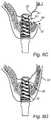
- FIG. 5Ais a perspective view of the implantation site when accessing the alveolar arch
- FIG. 5Bis a perspective view of the implantation site of FIG. 5A during preparation of an implementation hole
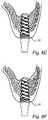
- FIG. 5Cis an enlarged perspective view of the implantation site showing the screwing action of a dental implant according to this invention.
- FIG. 5Dis a perspective view of the implantation site showing the dental implant in its final position within the alveolar arch;
- FIG. 5Eis a perspective view of the implantation site after healing and installation of a dental prosthesis.
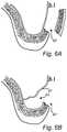
- FIG. 6Ais a cross-sectional view of the implantation site with a fenestration when accessing the alveolar arch;
- FIG. 6Bis a cross sectional view of the implantation site after elevation of the maxillary sinus membrane
- FIG. 6Cis a cross sectional view of the implantation site of a dental implant in site after insertion through bone into the prepared compartment existing after the elevation of the sinus membrane;
- FIG. 6Dis a cross sectional view of the implantation site showing the dental implant in its final position within the alveolar arch and the fenestration reinstated;
- FIG. 6Eis a cross sectional view of the implantation site during healing.
- FIG. 6Fis a cross sectional view of the implantation site after healing.
- FIG. 1Ashows an implant system comprising an abutment 10 , an abutment screw 20 , and a dental implant 30 according to the invention.
- the abutment 10 and the abutment screw 20may be replaced by any other prosthetic components of the art.
- the dental implant 30 of FIG. 1Asubstantially has a frusta-conical shape.
- This general shapeis merely one of the preferred general shapes of the invention as will be seen below (e. g. FIGS. 4A-4C , and FIGS. 5C-5E ).
- the body of the implant 30comprises a coronal end 31 and an apical end 32 .
- an interface 160for mounting prosthetic components, such as an abutment and an abutment screw 20 .
- an interface to a prosthetic componentas defined in U.S. Pat. No. 6,733,291 B1, US 2011/0020767 A1, US 2012/0021381 A1, U.S. Pat. No. 8,038,442 B2 or U.S. Pat. No. 4,960,381 A may be included.
- the implant 30is provided with a blunt tip 39 .
- the dental implant 30is provided with an external thread 40 , starting at the apical end 32 and spiraling along the outer side of the implant 30 toward the coronal end 31 .
- the thread profile of the external thread 40may change along the length of the implant 30 .
- the thread profilemay have a reduced thread depth compared to the thread profile at the coronal end 31 . In between, the thread depths gradually increase.
- Such a thread geometry combined with the helical fluteis one way to provide the implant 30 with a self-tapping feature.
- the thread 40 shown in FIG. 1Ais a double thread.
- one, three or four threadsmay be provided along the outer side of dental implant 30 .
- a double threadis used.
- Two or more threadshave an advantageous effect on the characteristics of the implant 30 . More specifically, by using a plurality of threads 40 along the implant 30 , the risk of misalignment while screwing in the implant 30 is significantly reduced.
- the double thread 40enters the bone tissue symmetrically so that even in the beginning of insertion, the center of rotation of the implant 30 is practically identical to the longitudinal axis 2 of the implant 30 . Consequently, the likelihood of tilting of the implant 30 during insertion is reduced.
- two or more threads 40also provide for a symmetric loading of the bone tissue while tightening the implant 30 .
- the bone tissuealso experiences less wear since, for example, the lead of a double thread 40 is greater than the pitch of a single thread 40 so that less length of the thread's flank is passing by the entry point at the implantation hole 86 in FIG. 5B .
- the term pitchis used in the following for the distance between two crests of a single thread as well as for the distance between two crests belonging to the same thread of a. double thread.
- the implant 30includes a blunt tip 39 .
- the blunt tip 39is formed so that soft tissue in contact with said tip 39 is not damaged or pierced.
- An implant according to the present inventionis also provided with at least one helical cutting flute 50 spiraling in the opposite direction to the external thread 40 .
- the cutting flute 50comprises a coronal flank 51 , an apical flank 53 and a flute base 52 connecting the inner edges of the apical flank 53 and coronal flank 51 .
- the profile of the cutting flutemay be at least partly curved.
- the flute base 52may merge with either of the coronal flank 51 or the apical flank 53 .
- the coronal flank 51may directly connect to the apical flank 53 at a point closest to the longitudinal axis 2 . However, in all of these configurations, the coronal flank 51 constitutes a cutting edge 54 and will act as cutting flank.
- the coronal flank 51is longer (as seen from the side) than the apical flank 53 .
- the flute base 52 in FIG. 1Ais not running parallel to the longitudinal axis 2 of said implant 30 . Instead, the flute base 52 is inclined toward the central axis 2 in the direction of the coronal end 31 . In other words, the depth as measured from the outer side of implant 30 , i. e. the envelope surface of implant 30 , of said flute base 52 decreases from the coronal end 31 to the apical end 32 .
- the cutting flutehelically runs from the apical end portion 32 along the outer side of implant 30 toward the coronal end 31 and preferably ends at a height so that at least one crest of thread 40 as seen in the longitudinal cross-section along the central axis 2 remains. However, preferably, two crests of thread 40 along the outer side of implant 30 remain in the coronal direction along central axis 2 after tapering off of the helical flute 50 .
- the helical flute 50preferably circumvents the implant 30 at least twice.
- the pitch of the fluteshall be within the interval 2-4 pitches of the thread, preferably 2.5-3.5 thread pitches.
- the helical flute 50preferably exits within the blunt tip portion 39 .
- the helical flute 50opens up at the blunt tip portion 39 facing away from the implant 30 in its longitudinal direction (cf. FIG. 3B ).
- the edges formed between the helical flute 50 and the blunt tip 39may be chamfered or rounded.
- the cutting flutespirals along the outer side of implant 30 in the opposite direction to the external thread 40 .
- the flute 50intersects the external thread 40 .
- This intersection with the external thread 40causes the coronal flank 51 to form a cutting edge 54 .
- Said cutting edge 54enables the external thread 40 to be self-tapping.
- Cuttingis performed at the cutting edge 54 belonging to the coronal flank 51 , the coronal flank 51 being longer than the apical flank 53 .
- the cutting flute 50needs to have a higher depth than the external thread 40 .
- the flutehas an at least 40% to 200% greater depth than the depth of the external thread 40 . Consequently, the depth of the apical flank 53 has to be at least 40% deeper than the depth of thread 40 .
- two cutting fluteshave one advantage that their symmetric configuration provides for a symmetric distribution of cutting forces that are caused by the cutting edge while creating the female thread in the surrounding bone tissue.
- the cutting flute 50 spiraling along the implantalso has the advantage, that the length of the cutting edge 54 is increased in comparison to cutting flutes known from the prior art that commonly run along the implant's longitudinal direction. Such an increased length of the cutting edge 54 provides for an even distribution of cutting forces and a more equal distribution of cut off bone tissue as well as its collection in the helical flute 50 .
- the lead of the cutting flute 50 , 150is higher than the lead of the external thread 40 , 140 , respectively. Since the lead of the flute 50 , 150 is higher than the lead of the external thread 40 , 140 , at least parts of the bone debris is transported a shorter distance, relative to the direction of insertion, than the implant 130 itself. More specifically, bone tissue is cut off by the cutting edge and is subsequently being positioned within the flute 50 , 150 . However, the cut off bone tissue is at least not fully attached to the cutting flute 50 , 150 but, instead, will tend to move in the apical direction of the implant 30 , 130 . Consequently, the bone debris will be transported toward the apical end 31 , 131 of said implant 30 , 130 during insertion of the implant.
- the hole prepared for implantation of said implant 30has at least a diameter that allows the implant 30 to be inserted partly into the bone tissue until the surrounding rim of the implantation hole touches the apical flank of the thread 40 .
- the blunt tip 39is generally formed as a plane surface facing away from the implant in the longitudinal direction. Naturally, it is within the scope of the invention to replace the flat surface with a curved protrusion such as the one shown in FIG. 3 . Such a rounded tip also provides protection to soft tissue such as the mucous membrane.
- the blunt tipin its rounded configuration does not only support the mucous membrane for creating or maintaining the space provided between the sinus floor and the mucous membrane but is also adapted to the shape of the membrane under tension.
- the implant with its blunt tipacts like a post for a tent.
- the implant 30 of FIG. 1Ahas a frusta-conical shape that is tapered toward its apical end 32 . Such a shape makes it possible to continuously cut off of bone tissue along the outer side of the implant 30 . More specifically, the diameter of the implantation hole prepared prior insertion of the implant is preferably chosen to be as small as possible. This allows the implant 30 to be inserted with its blunt tip until the self-tapping thread 14 of the implant 30 contacts the circumferential rim of the implantation hole. In this way, the hole provides for an initial guidance of the implant into the implantation hole.
- the conical form of the implant 30results in the cutting edge 54 not only cutting the thread geometry but at the same time increasing the diameter of the prefabricated implantation hole.
- the implant 30may also acts like a drill during implantation, in particular if the depth of the flute 50 is higher than the height of the external thread 40 .
- the implantexits the bone and enters into the maxillary sinus.
- the implant 30may pass through the bone.
- the soft membrane covering the bone inside the maxillary sinusshould not be damaged. This is achieved by providing a blunt tip 39 to the implant 30 .
- alternative proceduresare using an implant in accordance with the present invention.
- elevating the membrane prior to the insertion of the implant through a fenestration 87may serve to reduce the risk for soft membrane to be damaged during the procedure.
- a method following such a principleis disclosed in FIG. 6 a -6 f It is acknowledged that according to a presently preferred method the membrane is elevated prior to inserting the implant.
- the blunt tip of the implantminimizes the risk that the membrane is perforated after insertion of the implant.
- the void created between the sinus floor and the mucous membraneis thereby partly filled with bone tissue, which enhances the formation of new bone and, thus, improves the stability of the implant.
- the dental implant of the present inventionmay be used in patients, in which it is of advantage to use bone augmentation for providing an improved stability within the bone tissue.
- FIG. 1Banother embodiment of the implant similar to the one shown in FIG. 1A is disclosed.
- features, advantages and effects previously described for the dental implant of FIG. 1Aalso apply to the implant of FIG. 1B .
- features corresponding to features of the previous embodimentare denoted with associated reference numbers, i. e. the reference numbers have been increased by multiples of one hundred.
- Thisalso applies to all other embodiments described below.
- the previously described features of the flute 50also apply to the flute 150 of the present embodiment as well as to, for example, flute 350 of FIG. 3 .
- the structural features and their modifications described for the external thread 40also apply to the external thread 140 or 440 (see FIG. 5C ).
- the embodiment of the dental implant 130 shown in FIG. 1Bcomprises a coronal section 133 and an apical section 134 .
- the coronal section 133is frusta-conical but may also be cylindrical.
- the apical section 134is designed to be frusta-conical in order to accumulate bone tissue in the form of bone debris to be subsequently used for bone augmentation, preferably in the apical periphery of implant 130 .
- there is a knee 135due to a difference in cone angles ⁇ and ⁇ of the apical section 134 and the coronal section 133 , respectively.
- the cone angle ⁇ of the apical section 134is greater than the cone angle ⁇ of the coronal section 133 .
- the apical section 134also serves to increase the diameter of the implantation hole.
- the coronal section 133is primarily intended for providing primary stability by creating a press fit.
- the bone tissueis compressed in order to generate a press fit between the surface of the thread 140 and the surrounding bone tissue. This may be achieved by letting the flute 150 start to taper off after crossing the knee 135 in the coronal direction.
- the keyis to have the flute extending all the way to the blunt tip for discharging of bone debris and the tapering may be used to facilitate discharging into the maxillary sinus void.
- the flute 150extends beyond the knee up to the second last thread of the external thread 140 as seen in the longitudinal cross-section along the central axis 102 .
- the final geometry of the external thread 140is reached at the height of the knee 135 .
- Thismay also solely apply to the height of the thread flanks (see FIG. 2 ).
- the width of a thread between a thread root and an adjacent thread rootmay well increase starting from the apical end 132 beyond the knee 135 , even up to the coronal end 131 .
- Such a design of the external thread 140additionally provides primary stability of the implant. More details concerning the geometry of such a thread may be taken from NobelActive U.S. Pat. No. 8,038,442 B2 and US 2012/0021381.
- FIG. 3Ba front view of a blunt tip is shown.
- This embodiment of a blunt tipis formed by a curved protrusion at the apical end 332 of the implant 330 .
- the cutting flute(s) 350exit(s) at the blunt tip of the implant 330 .
- bone debrismay be transported out of the apical end of the flute, for example into a void space between the sinus floor and the sinus membrane.
- FIG. 2shows a longitudinal cross-section of implant 130 along the line II-II shown in FIG. 1B .
- the coronal flank with the cutting edge 154is tilted by an angle ⁇ about the normal to the longitudinal axis of the implant.
- bone tissue cut by the cutting edge 154propagates in the direction of the flute basis 152 while bone is cut off the circumferential wall of the implantation hole during insertion of the implant 130 .
- FIGS. 4A to 4Cshow different shapes applied to the dental implant.
- the embodiment shown in FIG. 4Acorresponds to the embodiment shown in FIG. 1A .
- the coronal as well as the apical sectionhave the same cone angle so that the whole implant 30 substantially has a frusta-conical shape.
- implant 230 shown in FIG. 4Bis designed to be basically cylindrical along its length.
- the embodiment of FIG. 4Cshows another side view of the implant 130 of FIG. 1B and FIG. 2 .
- FIG. 5Aan incision is made into the gingival tissue exposing the underlying bone where a hole for implantation shall be drilled.
- a drill 70is used to drill the implantation hole 86 .
- the drill 70 in FIG. 5Bis depicted as a step drill, a drill without a step may also be used.
- the implantation hole 86is not prepared as a through hole during the drilling step in order to prevent the mucous membrane located on the posterior side of the alveolar arch from being damaged.
- a drill that does not damage soft tissuemay be used to create the implantation hole 86 as a through hole extending throughout the alveolar arch.
- FIG. 5Cshows the insertion of an implant 430 according to the present invention.
- the coronal flank of the flute 450cuts off bone debris 80 from the inner wall of implantation hole 86 .
- the bone debris 80is urged along the helical flute towards the apical end 432 of implant 430 while said implant is screwed into the implantation hole 86 .
- a void space 83has been created by lifting the mucous membrane 81 above the surface of the alveolar arch 84 . Since the bone debris on the sides of hole 86 is transported towards the apical end of implant 430 , it enters the void space 83 by exiting the flute, where the flute arrangement 450 exits or at the part of the flute extending into said space 83 . The accumulation 85 of the bone debris stimulates bone augmentation in the space between the sinus floor and the sinus membrane.
- the sinus membrane 81may have been lifted off the alveolar arch by screwing in the implant 430 or by any other means or technique known by the skilled person as exemplified in a previous section.
- the gingival tissuemay be intermittently closed by fastening means, such as a suture or clamps, or by glue for an undisturbed healing process.
- fastening meanssuch as a suture or clamps, or by glue for an undisturbed healing process.
- an intermediate or a final prosthesismay be placed on said implant 430 .
- prosthesis 90may be attached to the anchored implant 430 .
- bone augmentationhas successfully been achieved without causing damage to the sinus membrane 81 .
- an implant according to the present inventionmay include at least one of a modified surface or a coating on at least part of its surface to enhance osseointegration.
- a modified surface or a coating on at least part of its surface to enhance osseointegrationis the TiUnite® surface marketed by Nobel Biocare®.
- the present inventionprovides a new generation of implant that may be applied in cases with insufficient bone quality or quantity.
- the previous embodimentsare intended for explanatory purposes only, whereas the scope of protection is defined by the following independent claims. Further combinations of features defining preferred embodiments are stated in the dependent claims.
Landscapes
- Health & Medical Sciences (AREA)
- Oral & Maxillofacial Surgery (AREA)
- Orthopedic Medicine & Surgery (AREA)
- Dentistry (AREA)
- Epidemiology (AREA)
- Life Sciences & Earth Sciences (AREA)
- Animal Behavior & Ethology (AREA)
- General Health & Medical Sciences (AREA)
- Public Health (AREA)
- Veterinary Medicine (AREA)
- Otolaryngology (AREA)
- Dental Prosthetics (AREA)
- Prostheses (AREA)
Abstract
Description
Claims (29)
Applications Claiming Priority (4)
| Application Number | Priority Date | Filing Date | Title |
|---|---|---|---|
| GB1404047.1 | 2014-03-07 | ||
| GB1404047 | 2014-03-07 | ||
| GB1404047.1AGB2523827A (en) | 2014-03-07 | 2014-03-07 | Dental implant |
| PCT/EP2015/054591WO2015132331A1 (en) | 2014-03-07 | 2015-03-05 | Dental implant |
Publications (2)
| Publication Number | Publication Date |
|---|---|
| US20170071703A1 US20170071703A1 (en) | 2017-03-16 |
| US11058522B2true US11058522B2 (en) | 2021-07-13 |
Family
ID=50554687
Family Applications (1)
| Application Number | Title | Priority Date | Filing Date |
|---|---|---|---|
| US15/123,573ActiveUS11058522B2 (en) | 2014-03-07 | 2015-03-05 | Dental implant |
Country Status (11)
| Country | Link |
|---|---|
| US (1) | US11058522B2 (en) |
| EP (1) | EP3113716B1 (en) |
| JP (1) | JP6701084B2 (en) |
| KR (1) | KR102384530B1 (en) |
| CN (1) | CN106061429B (en) |
| AU (1) | AU2015226166B2 (en) |
| BR (1) | BR112016020574B1 (en) |
| CA (1) | CA2941664C (en) |
| GB (1) | GB2523827A (en) |
| WO (1) | WO2015132331A1 (en) |
| ZA (1) | ZA201605724B (en) |
Families Citing this family (13)
| Publication number | Priority date | Publication date | Assignee | Title |
|---|---|---|---|---|
| US11331168B2 (en)* | 2015-08-11 | 2022-05-17 | Biomet 3I, Llc | Dental implant having tapered threaded surface with installation enhancement features |
| CN106618767B (en)* | 2016-12-29 | 2023-03-24 | 北京爱康宜诚医疗器材有限公司 | Implant body |
| WO2019111041A1 (en) | 2017-12-06 | 2019-06-13 | Stryker European Holdings I, Llc | Orthopedic locking screw |
| DE102017012134B3 (en)* | 2017-12-28 | 2019-03-07 | Ljubinko Petrovic | Bone implant with an anchoring part made of a biocompatible plastic |
| CN108236508B (en)* | 2018-03-14 | 2023-12-15 | 华南理工大学 | NiTi memory personalized self-expansion thread groove embedded porous structure implant and manufacturing method thereof |
| EP3806756B1 (en) | 2018-06-13 | 2024-01-03 | Stryker European Operations Limited | Bone fragment collector and processor |
| CN109223213A (en)* | 2018-11-01 | 2019-01-18 | 中南大学湘雅三医院 | Porous titanium implant body suitable for Dental implantion |
| JP7305283B2 (en)* | 2019-11-28 | 2023-07-10 | 株式会社松風 | Implant fixture with tapered thread groove depth |
| EP4076290B1 (en) | 2019-12-18 | 2024-07-31 | Stryker European Operations Limited | Bone fragment collector and processor |
| KR20220081547A (en)* | 2020-12-09 | 2022-06-16 | 주식회사 메가젠임플란트 | Dental Implant Fixture |
| CN113974927B (en)* | 2021-12-24 | 2022-05-03 | 北京爱康宜诚医疗器材有限公司 | Intermediate implants for implantable prostheses |
| CN115444597A (en)* | 2022-08-16 | 2022-12-09 | 广东健齿生物科技有限公司 | Two-way threaded dental implant |
| CN120078535B (en)* | 2025-03-31 | 2025-08-26 | 威海华迈医疗器械科技有限公司 | A dental implant based on a bidirectional thread structure |
Citations (76)
| Publication number | Priority date | Publication date | Assignee | Title |
|---|---|---|---|---|
| US4697969A (en) | 1985-09-06 | 1987-10-06 | Sparkes Wilford S | Wood screw |
| US4871313A (en) | 1987-09-08 | 1989-10-03 | Les Fils D'auguste Maillefer, Societe Anonyme A Ballaigues | Dental pin |
| JPH06319759A (en) | 1993-04-27 | 1994-11-22 | Medevelop Ab | Fixing element to be implanted in tissue for holding prosthesis, artificial joint component part, and the like |
| RO110899B1 (en) | 1995-03-20 | 1996-05-30 | Deac Valeriu | Ostheointegrated implant for fixed, protected action |
| US5601429A (en) | 1995-08-11 | 1997-02-11 | Blacklock; Gordon D. | Dental implant anchor |
| US5628630A (en) | 1994-12-15 | 1997-05-13 | Univ. Of Alabama At Birmingham | Design process for skeletal implants to optimize cellular response |
| US5667348A (en) | 1996-05-15 | 1997-09-16 | Chen; Sen-Yang | Screw for fibrous boards |
| US5759003A (en) | 1996-07-22 | 1998-06-02 | Greenway; John Michael | Combined screw and clearance drill |
| US5772374A (en) | 1996-01-08 | 1998-06-30 | Aoyama Seisakusho Co., Ltd. | Tapping screw and mechanism of engaging member to be engaged using the same |
| US5891146A (en)* | 1997-10-15 | 1999-04-06 | Applied Biological Concepts, Inc. | Wedge orthopedic screw |
| US5897319A (en) | 1997-09-12 | 1999-04-27 | Sulzer Calcitek Inc. | Self-tapping implant with helical flutes |
| US5902109A (en) | 1996-01-18 | 1999-05-11 | Implant Innovations, Inc. | Reduced friction screw-type dental implant |
| EP1030622A1 (en) | 1997-11-11 | 2000-08-30 | Nobel Biocare AB (publ) | Arrangement for obtaining reliable anchoring of a threaded implant in bone |
| US6135772A (en) | 1994-08-15 | 2000-10-24 | Jones; Shedrick D. | Method and apparatus for implantation |
| US6273722B1 (en) | 1999-11-29 | 2001-08-14 | Swiss Implants, Inc. | Hybrid press fit-threaded dental implant |
| US6312472B1 (en) | 1997-11-11 | 2001-11-06 | Nobel Biocare Ab | Biocompatible medical implant element |
| US6382976B1 (en) | 2001-02-05 | 2002-05-07 | Sulzer Dental Inc. | Dental implant having round bottom with fluid directing channels |
| US6402515B1 (en) | 2001-01-10 | 2002-06-11 | Sulzer Dental Inc. | Dental implant with variable profile thread |
| US6419708B1 (en) | 1997-04-30 | 2002-07-16 | Nobel Biocare Ab | Calcium-phosphate coated implant element |
| US6450748B1 (en) | 2000-05-30 | 2002-09-17 | Tai-Ping Hsu | Screw having a screw thread formed with concave facets |
| US20020182567A1 (en)* | 2001-06-04 | 2002-12-05 | Hurson Steven M. | Natural implant system |
| US6604945B1 (en) | 1994-08-15 | 2003-08-12 | Shedrick D. Jones | Method and apparatus for implantation |
| US20030228556A1 (en)* | 2002-06-07 | 2003-12-11 | Giorno Thierry M. | Prosthetic mounting device |
| US6679701B1 (en) | 2000-03-23 | 2004-01-20 | Gordon D. Blacklock | Anchor having threads opposing unthreading |
| US6730129B1 (en) | 1999-05-31 | 2004-05-04 | Nobel Biocare Ab | Implant for application in bone, method for producing such an implant, and use of such an implant |
| US20040121289A1 (en)* | 2002-12-23 | 2004-06-24 | Miller Robert Jeffrey | Dental implant |
| WO2004058091A1 (en) | 2002-12-30 | 2004-07-15 | Nobel Biocare Ab (Publ) | Implant arrangement |
| US6918766B1 (en) | 1999-05-31 | 2005-07-19 | Nobel Biocare Ab | Method, arrangement and use of an implant for ensuring delivery of bioactive substance to the bone and/or tissue surrounding the implant |
| US20050221258A1 (en) | 2001-07-04 | 2005-10-06 | Nobel Biocare Ab | Implant for example dental implant |
| US7008226B2 (en) | 2002-08-23 | 2006-03-07 | Woodwelding Ag | Implant, in particular a dental implant |
| US7048541B2 (en) | 2000-04-04 | 2006-05-23 | Nobel Biocare Ab | Implant having attachment and hole-insert parts, and method for producing such an implant |
| JP2006212449A (en) | 1996-08-26 | 2006-08-17 | Shedrick D Jones | Prosthesis supporting device and apparatus for implantation |
| DE102006013456A1 (en) | 2006-03-23 | 2007-09-27 | Gebr. Brasseler Gmbh & Co. Kg | Dental implant |
| US20080227057A1 (en)* | 2005-02-08 | 2008-09-18 | Biotechnology Institute.I Mas D. S.L. | Narrow Dental Implant and Associated Parts |
| US20080261175A1 (en)* | 2007-04-23 | 2008-10-23 | Nobel Biocare Services Ag | Dental implant |
| US7491058B2 (en) | 2002-06-27 | 2009-02-17 | Nobel Biocare Services Ag | Dental implant spacer and adapter assembly |
| EP2095790A1 (en) | 2008-02-28 | 2009-09-02 | Eugenio Gastaldi | Bio-compatible device for dental bone implantation for anatomical restoration |
| US7597557B2 (en) | 2003-05-21 | 2009-10-06 | Nobel Biocare Services Ag | Condensing skeletal implant that facilitate insertions |
| US20090258328A1 (en) | 2006-11-30 | 2009-10-15 | Chun-Leon Chen | 5 in 1 dental implant method and apparatus |
| US20100009316A1 (en) | 2008-07-14 | 2010-01-14 | Hurson Steven M | Compact dental implant |
| US20100055643A1 (en)* | 2008-08-29 | 2010-03-04 | Hung William Y S | Dental implant |
| US7699881B2 (en) | 2003-10-29 | 2010-04-20 | Ulrich Gmbh & Co. Lg | Bone screw |
| US7708558B1 (en) | 1999-05-31 | 2010-05-04 | Nobel Biocare Ab (Publ.) | Implant, method for producing the implant, and use of the implant |
| US7713292B2 (en) | 2003-04-30 | 2010-05-11 | Biedermann Motech Gmbh | Bone anchoring element with thread that can be unscrewed |
| US7713307B1 (en) | 1999-05-31 | 2010-05-11 | Nobel Biocare Ab (Publ.) | Layer arranged on implant for bone or tissue structure |
| US20100190138A1 (en) | 2009-01-27 | 2010-07-29 | Intra-Lock International, Inc. | Self-Clearing Self-Cutting Implant |
| WO2010108794A1 (en) | 2009-03-23 | 2010-09-30 | Astra Tech Ab | Bone fixture |
| US20110033826A1 (en) | 2006-11-30 | 2011-02-10 | Chun-Leon Chen | Implant root for tooth implanting |
| US8038442B2 (en) | 2007-04-23 | 2011-10-18 | Nobel Biocare Services Ag | Dental implant and dental component connection |
| EP2377491A2 (en) | 2010-04-15 | 2011-10-19 | Chun-Leon Chen | One-piece obliquely implanted dental implant |
| EP2377490A2 (en) | 2010-04-15 | 2011-10-19 | Chun-Leon Chen | Abutment extender for one piece implant |
| US20110294094A1 (en)* | 2010-06-01 | 2011-12-01 | Mark Moshavi | Implant and method |
| EP2392289A1 (en) | 2010-06-04 | 2011-12-07 | Chun-Leon Chen | Restorable one piece implant |
| US20120015325A1 (en)* | 2010-07-13 | 2012-01-19 | Chun-Leon Chen | Restorable one piece implant |
| US8100985B2 (en) | 2001-07-04 | 2012-01-24 | Nobel Biocare Ab (Publ.) | Method for treating an implant, and such an implant |
| US8113834B2 (en) | 2002-07-25 | 2012-02-14 | Nobel Biocare Ab (Publ) | Arrangement of two or more implants provided with growth-stimulating substance(s) |
| US8167618B2 (en) | 2002-07-25 | 2012-05-01 | Nobel Biocare Ab (Publ) | Arrangement for using osteoinductive or bioactive material to induce bone and/or increase the stability of implants in the jaw bone, and an implant intended for this purpose |
| US20120225407A1 (en)* | 2010-07-13 | 2012-09-06 | Chun-Leon Chen | Restorable zirconium dioxide-based one piece dental implant |
| CN102697570A (en) | 2012-06-15 | 2012-10-03 | 西北有色金属研究院 | Dental implant |
| US20130022942A1 (en) | 2011-07-20 | 2013-01-24 | Zadeh Parsa T | Self-osteotomizing and grafting bone implant |
| US20130045462A1 (en) | 2011-08-17 | 2013-02-21 | Yu-Hong Tzeng | Dental implant fixing system |
| US8439919B2 (en) | 2000-04-04 | 2013-05-14 | Nobel Biocare Services Ag | Implant provided with attachment and hole-insert parts, and a method for producing such an implant |
| US20130224687A1 (en) | 2009-11-03 | 2013-08-29 | Ben-Zion Karmon | Dental implant |
| CN103271774A (en) | 2013-06-07 | 2013-09-04 | 大连三生科技发展有限公司 | Micro screw implant |
| US20130273500A1 (en) | 2009-02-02 | 2013-10-17 | Thierry Giorno | Dental Implant and Method for Rapid Integration |
| WO2013157756A1 (en) | 2012-04-19 | 2013-10-24 | Hwang Jeong Bin | Tooth implant |
| EP2656813A1 (en) | 2012-04-26 | 2013-10-30 | Chun-Leon Chen | Restorable zirconium dioxide-based one piece dental implant |
| US20140023990A1 (en) | 2012-07-19 | 2014-01-23 | Parsa T. Zadeh | Self-osteotomizing bone implant and related method |
| US20140045144A1 (en) | 2012-08-07 | 2014-02-13 | Mazen Dukhan | Dental Implant and Method of Implantation |
| WO2014026706A1 (en) | 2012-08-13 | 2014-02-20 | Camlog Biotechnologies Ag | Secondary part, set, dental implant, gingiva shaper, impression part, dental implant system, and method for producing an implant |
| US8764443B2 (en) | 2001-12-21 | 2014-07-01 | Nobel Biocare Services Ag | Method for producing a surface structure on an implant, and such an implant |
| US8771361B2 (en) | 2002-07-25 | 2014-07-08 | Nobel Biocare Services Ag | Arrangement for increasing the stress resistance of implants and one such implant |
| US8827703B2 (en) | 2001-12-21 | 2014-09-09 | Nobel Biocare Services Ag | Implant, and method and system for producing such an implant |
| US20150215696A1 (en)* | 2014-01-30 | 2015-07-30 | Cochlear Limited | Bone conduction implant |
| WO2015118543A1 (en) | 2014-02-05 | 2015-08-13 | Ophir Fromovich | Dental implant for bone collection and distribution |
| WO2015125139A2 (en) | 2014-02-20 | 2015-08-27 | MIS Implants Technologies Ltd. | Dental implant |
Family Cites Families (2)
| Publication number | Priority date | Publication date | Assignee | Title |
|---|---|---|---|---|
| KR101191257B1 (en)* | 2011-03-09 | 2012-10-16 | 주식회사 바이오제네시스 | Dental implant fixture |
| US9901379B2 (en)* | 2012-08-24 | 2018-02-27 | Rtg Scientific | Orthopedic fastener device |
- 2014
- 2014-03-07GBGB1404047.1Apatent/GB2523827A/ennot_activeWithdrawn
- 2015
- 2015-03-05USUS15/123,573patent/US11058522B2/enactiveActive
- 2015-03-05AUAU2015226166Apatent/AU2015226166B2/enactiveActive
- 2015-03-05BRBR112016020574-0Apatent/BR112016020574B1/enactiveIP Right Grant
- 2015-03-05KRKR1020167027836Apatent/KR102384530B1/enactiveActive
- 2015-03-05EPEP15708201.7Apatent/EP3113716B1/enactiveActive
- 2015-03-05JPJP2016552926Apatent/JP6701084B2/enactiveActive
- 2015-03-05WOPCT/EP2015/054591patent/WO2015132331A1/enactiveApplication Filing
- 2015-03-05CNCN201580012280.0Apatent/CN106061429B/enactiveActive
- 2015-03-05CACA2941664Apatent/CA2941664C/enactiveActive
- 2016
- 2016-08-17ZAZA2016/05724Apatent/ZA201605724B/enunknown
Patent Citations (84)
| Publication number | Priority date | Publication date | Assignee | Title |
|---|---|---|---|---|
| US4697969A (en) | 1985-09-06 | 1987-10-06 | Sparkes Wilford S | Wood screw |
| US4871313A (en) | 1987-09-08 | 1989-10-03 | Les Fils D'auguste Maillefer, Societe Anonyme A Ballaigues | Dental pin |
| JPH06319759A (en) | 1993-04-27 | 1994-11-22 | Medevelop Ab | Fixing element to be implanted in tissue for holding prosthesis, artificial joint component part, and the like |
| US6135772A (en) | 1994-08-15 | 2000-10-24 | Jones; Shedrick D. | Method and apparatus for implantation |
| US6604945B1 (en) | 1994-08-15 | 2003-08-12 | Shedrick D. Jones | Method and apparatus for implantation |
| US5628630A (en) | 1994-12-15 | 1997-05-13 | Univ. Of Alabama At Birmingham | Design process for skeletal implants to optimize cellular response |
| RO110899B1 (en) | 1995-03-20 | 1996-05-30 | Deac Valeriu | Ostheointegrated implant for fixed, protected action |
| US5601429A (en) | 1995-08-11 | 1997-02-11 | Blacklock; Gordon D. | Dental implant anchor |
| US5772374A (en) | 1996-01-08 | 1998-06-30 | Aoyama Seisakusho Co., Ltd. | Tapping screw and mechanism of engaging member to be engaged using the same |
| US5902109A (en) | 1996-01-18 | 1999-05-11 | Implant Innovations, Inc. | Reduced friction screw-type dental implant |
| US5667348A (en) | 1996-05-15 | 1997-09-16 | Chen; Sen-Yang | Screw for fibrous boards |
| US5759003A (en) | 1996-07-22 | 1998-06-02 | Greenway; John Michael | Combined screw and clearance drill |
| JP2006212449A (en) | 1996-08-26 | 2006-08-17 | Shedrick D Jones | Prosthesis supporting device and apparatus for implantation |
| US6419708B1 (en) | 1997-04-30 | 2002-07-16 | Nobel Biocare Ab | Calcium-phosphate coated implant element |
| US5897319A (en) | 1997-09-12 | 1999-04-27 | Sulzer Calcitek Inc. | Self-tapping implant with helical flutes |
| US5891146A (en)* | 1997-10-15 | 1999-04-06 | Applied Biological Concepts, Inc. | Wedge orthopedic screw |
| US6312472B1 (en) | 1997-11-11 | 2001-11-06 | Nobel Biocare Ab | Biocompatible medical implant element |
| EP1030622A1 (en) | 1997-11-11 | 2000-08-30 | Nobel Biocare AB (publ) | Arrangement for obtaining reliable anchoring of a threaded implant in bone |
| US8152856B2 (en) | 1999-05-31 | 2012-04-10 | Nobel Biocare Ab (Publ.) | Layer arranged on implant for bone or tissue structure, such an implant, and a method for application of the layer |
| US8349009B2 (en) | 1999-05-31 | 2013-01-08 | Nobel Biocare Services Ag | Implant, method for producing the implant, and use of the implant |
| US7713307B1 (en) | 1999-05-31 | 2010-05-11 | Nobel Biocare Ab (Publ.) | Layer arranged on implant for bone or tissue structure |
| US6918766B1 (en) | 1999-05-31 | 2005-07-19 | Nobel Biocare Ab | Method, arrangement and use of an implant for ensuring delivery of bioactive substance to the bone and/or tissue surrounding the implant |
| US20100112519A1 (en) | 1999-05-31 | 2010-05-06 | Nobel Biocare Ab | Implant, method for producing the implant, and use of the implant |
| US7708558B1 (en) | 1999-05-31 | 2010-05-04 | Nobel Biocare Ab (Publ.) | Implant, method for producing the implant, and use of the implant |
| US6730129B1 (en) | 1999-05-31 | 2004-05-04 | Nobel Biocare Ab | Implant for application in bone, method for producing such an implant, and use of such an implant |
| US6273722B1 (en) | 1999-11-29 | 2001-08-14 | Swiss Implants, Inc. | Hybrid press fit-threaded dental implant |
| US6679701B1 (en) | 2000-03-23 | 2004-01-20 | Gordon D. Blacklock | Anchor having threads opposing unthreading |
| US7048541B2 (en) | 2000-04-04 | 2006-05-23 | Nobel Biocare Ab | Implant having attachment and hole-insert parts, and method for producing such an implant |
| US8439919B2 (en) | 2000-04-04 | 2013-05-14 | Nobel Biocare Services Ag | Implant provided with attachment and hole-insert parts, and a method for producing such an implant |
| US6450748B1 (en) | 2000-05-30 | 2002-09-17 | Tai-Ping Hsu | Screw having a screw thread formed with concave facets |
| US6402515B1 (en) | 2001-01-10 | 2002-06-11 | Sulzer Dental Inc. | Dental implant with variable profile thread |
| US6382976B1 (en) | 2001-02-05 | 2002-05-07 | Sulzer Dental Inc. | Dental implant having round bottom with fluid directing channels |
| US20020182567A1 (en)* | 2001-06-04 | 2002-12-05 | Hurson Steven M. | Natural implant system |
| US8657601B2 (en) | 2001-07-04 | 2014-02-25 | Nobel Biocare Services Ag | Implant for example dental implant |
| US8100985B2 (en) | 2001-07-04 | 2012-01-24 | Nobel Biocare Ab (Publ.) | Method for treating an implant, and such an implant |
| US20050221258A1 (en) | 2001-07-04 | 2005-10-06 | Nobel Biocare Ab | Implant for example dental implant |
| US8764443B2 (en) | 2001-12-21 | 2014-07-01 | Nobel Biocare Services Ag | Method for producing a surface structure on an implant, and such an implant |
| US8827703B2 (en) | 2001-12-21 | 2014-09-09 | Nobel Biocare Services Ag | Implant, and method and system for producing such an implant |
| US20030228556A1 (en)* | 2002-06-07 | 2003-12-11 | Giorno Thierry M. | Prosthetic mounting device |
| US7491058B2 (en) | 2002-06-27 | 2009-02-17 | Nobel Biocare Services Ag | Dental implant spacer and adapter assembly |
| US8167618B2 (en) | 2002-07-25 | 2012-05-01 | Nobel Biocare Ab (Publ) | Arrangement for using osteoinductive or bioactive material to induce bone and/or increase the stability of implants in the jaw bone, and an implant intended for this purpose |
| US8113834B2 (en) | 2002-07-25 | 2012-02-14 | Nobel Biocare Ab (Publ) | Arrangement of two or more implants provided with growth-stimulating substance(s) |
| US8771361B2 (en) | 2002-07-25 | 2014-07-08 | Nobel Biocare Services Ag | Arrangement for increasing the stress resistance of implants and one such implant |
| US7008226B2 (en) | 2002-08-23 | 2006-03-07 | Woodwelding Ag | Implant, in particular a dental implant |
| US20040121289A1 (en)* | 2002-12-23 | 2004-06-24 | Miller Robert Jeffrey | Dental implant |
| US20080032264A1 (en) | 2002-12-30 | 2008-02-07 | Nobel Biocare Services Ag | Implant arrangement |
| US8016593B2 (en) | 2002-12-30 | 2011-09-13 | Nobel Biocare Services Ag | Implant arrangement |
| US7281925B2 (en) | 2002-12-30 | 2007-10-16 | Nobel Biocare Services Ag | Implant arrangement |
| WO2004058091A1 (en) | 2002-12-30 | 2004-07-15 | Nobel Biocare Ab (Publ) | Implant arrangement |
| US7713292B2 (en) | 2003-04-30 | 2010-05-11 | Biedermann Motech Gmbh | Bone anchoring element with thread that can be unscrewed |
| US7597557B2 (en) | 2003-05-21 | 2009-10-06 | Nobel Biocare Services Ag | Condensing skeletal implant that facilitate insertions |
| US7699881B2 (en) | 2003-10-29 | 2010-04-20 | Ulrich Gmbh & Co. Lg | Bone screw |
| US20080227057A1 (en)* | 2005-02-08 | 2008-09-18 | Biotechnology Institute.I Mas D. S.L. | Narrow Dental Implant and Associated Parts |
| DE102006013456A1 (en) | 2006-03-23 | 2007-09-27 | Gebr. Brasseler Gmbh & Co. Kg | Dental implant |
| US20110033826A1 (en) | 2006-11-30 | 2011-02-10 | Chun-Leon Chen | Implant root for tooth implanting |
| US20090258328A1 (en) | 2006-11-30 | 2009-10-15 | Chun-Leon Chen | 5 in 1 dental implant method and apparatus |
| US7806693B2 (en) | 2007-04-23 | 2010-10-05 | Nobel Biocare Services Ag | Dental implant |
| US8038442B2 (en) | 2007-04-23 | 2011-10-18 | Nobel Biocare Services Ag | Dental implant and dental component connection |
| US20080261175A1 (en)* | 2007-04-23 | 2008-10-23 | Nobel Biocare Services Ag | Dental implant |
| EP2095790A1 (en) | 2008-02-28 | 2009-09-02 | Eugenio Gastaldi | Bio-compatible device for dental bone implantation for anatomical restoration |
| US20100009316A1 (en) | 2008-07-14 | 2010-01-14 | Hurson Steven M | Compact dental implant |
| US20100055643A1 (en)* | 2008-08-29 | 2010-03-04 | Hung William Y S | Dental implant |
| US20100190138A1 (en) | 2009-01-27 | 2010-07-29 | Intra-Lock International, Inc. | Self-Clearing Self-Cutting Implant |
| US20130273500A1 (en) | 2009-02-02 | 2013-10-17 | Thierry Giorno | Dental Implant and Method for Rapid Integration |
| WO2010108794A1 (en) | 2009-03-23 | 2010-09-30 | Astra Tech Ab | Bone fixture |
| US20130224687A1 (en) | 2009-11-03 | 2013-08-29 | Ben-Zion Karmon | Dental implant |
| EP2377491A2 (en) | 2010-04-15 | 2011-10-19 | Chun-Leon Chen | One-piece obliquely implanted dental implant |
| EP2377490A2 (en) | 2010-04-15 | 2011-10-19 | Chun-Leon Chen | Abutment extender for one piece implant |
| US20110294094A1 (en)* | 2010-06-01 | 2011-12-01 | Mark Moshavi | Implant and method |
| EP2392289A1 (en) | 2010-06-04 | 2011-12-07 | Chun-Leon Chen | Restorable one piece implant |
| US20120225407A1 (en)* | 2010-07-13 | 2012-09-06 | Chun-Leon Chen | Restorable zirconium dioxide-based one piece dental implant |
| US20120015325A1 (en)* | 2010-07-13 | 2012-01-19 | Chun-Leon Chen | Restorable one piece implant |
| US20130022942A1 (en) | 2011-07-20 | 2013-01-24 | Zadeh Parsa T | Self-osteotomizing and grafting bone implant |
| US20130045462A1 (en) | 2011-08-17 | 2013-02-21 | Yu-Hong Tzeng | Dental implant fixing system |
| WO2013157756A1 (en) | 2012-04-19 | 2013-10-24 | Hwang Jeong Bin | Tooth implant |
| EP2656813A1 (en) | 2012-04-26 | 2013-10-30 | Chun-Leon Chen | Restorable zirconium dioxide-based one piece dental implant |
| CN102697570A (en) | 2012-06-15 | 2012-10-03 | 西北有色金属研究院 | Dental implant |
| US20140023990A1 (en) | 2012-07-19 | 2014-01-23 | Parsa T. Zadeh | Self-osteotomizing bone implant and related method |
| US20140045144A1 (en) | 2012-08-07 | 2014-02-13 | Mazen Dukhan | Dental Implant and Method of Implantation |
| WO2014026706A1 (en) | 2012-08-13 | 2014-02-20 | Camlog Biotechnologies Ag | Secondary part, set, dental implant, gingiva shaper, impression part, dental implant system, and method for producing an implant |
| CN103271774A (en) | 2013-06-07 | 2013-09-04 | 大连三生科技发展有限公司 | Micro screw implant |
| US20150215696A1 (en)* | 2014-01-30 | 2015-07-30 | Cochlear Limited | Bone conduction implant |
| WO2015118543A1 (en) | 2014-02-05 | 2015-08-13 | Ophir Fromovich | Dental implant for bone collection and distribution |
| WO2015125139A2 (en) | 2014-02-20 | 2015-08-27 | MIS Implants Technologies Ltd. | Dental implant |
Non-Patent Citations (1)
| Title |
|---|
| International Search Report for Application No. PCT/EP2015/054591 dated May 26, 2016 in 3 pages [the ISR for the PCT Application of this US national phase application]. |
Also Published As
| Publication number | Publication date |
|---|---|
| BR112016020574B1 (en) | 2021-12-07 |
| AU2015226166A1 (en) | 2016-09-01 |
| CA2941664C (en) | 2022-06-21 |
| WO2015132331A1 (en) | 2015-09-11 |
| BR112016020574A2 (en) | 2017-08-15 |
| GB2523827A (en) | 2015-09-09 |
| CN106061429A (en) | 2016-10-26 |
| ZA201605724B (en) | 2017-11-29 |
| KR20160130838A (en) | 2016-11-14 |
| GB201404047D0 (en) | 2014-04-23 |
| JP6701084B2 (en) | 2020-05-27 |
| EP3113716A1 (en) | 2017-01-11 |
| CN106061429B (en) | 2020-06-02 |
| US20170071703A1 (en) | 2017-03-16 |
| JP2017506951A (en) | 2017-03-16 |
| EP3113716B1 (en) | 2021-08-18 |
| KR102384530B1 (en) | 2022-04-08 |
| AU2015226166B2 (en) | 2017-04-20 |
| CA2941664A1 (en) | 2015-09-11 |
Similar Documents
| Publication | Publication Date | Title |
|---|---|---|
| US11058522B2 (en) | Dental implant | |
| US10603140B2 (en) | Dental implant | |
| JP5275460B2 (en) | Medical implant and method of implantation | |
| CN101522131B (en) | Implants | |
| CN103476356B (en) | Holder | |
| KR102599230B1 (en) | Implant fixture having fine grooves | |
| KR100860356B1 (en) | A dendtal implant | |
| EP2623064B1 (en) | Implant for expanding the jawbone crest | |
| CN102920517A (en) | Artificial tooth implant fixing structure | |
| KR101191257B1 (en) | Dental implant fixture |
Legal Events
| Date | Code | Title | Description |
|---|---|---|---|
| AS | Assignment | Owner name:NOBEL BIOCARE SERVICES AG, SWITZERLAND Free format text:ASSIGNMENT OF ASSIGNORS INTEREST;ASSIGNORS:HALL, JAN;LUNDGREN, STEFAN;BERGMAN, GOERAN;AND OTHERS;SIGNING DATES FROM 20160928 TO 20161010;REEL/FRAME:042577/0473 | |
| STPP | Information on status: patent application and granting procedure in general | Free format text:NON FINAL ACTION MAILED | |
| STPP | Information on status: patent application and granting procedure in general | Free format text:RESPONSE TO NON-FINAL OFFICE ACTION ENTERED AND FORWARDED TO EXAMINER | |
| STPP | Information on status: patent application and granting procedure in general | Free format text:FINAL REJECTION MAILED | |
| STPP | Information on status: patent application and granting procedure in general | Free format text:DOCKETED NEW CASE - READY FOR EXAMINATION | |
| STPP | Information on status: patent application and granting procedure in general | Free format text:NON FINAL ACTION MAILED | |
| STPP | Information on status: patent application and granting procedure in general | Free format text:RESPONSE TO NON-FINAL OFFICE ACTION ENTERED AND FORWARDED TO EXAMINER | |
| STPP | Information on status: patent application and granting procedure in general | Free format text:FINAL REJECTION MAILED | |
| STPP | Information on status: patent application and granting procedure in general | Free format text:RESPONSE AFTER FINAL ACTION FORWARDED TO EXAMINER | |
| STPP | Information on status: patent application and granting procedure in general | Free format text:ADVISORY ACTION MAILED | |
| STPP | Information on status: patent application and granting procedure in general | Free format text:NON FINAL ACTION MAILED | |
| STPP | Information on status: patent application and granting procedure in general | Free format text:RESPONSE TO NON-FINAL OFFICE ACTION ENTERED AND FORWARDED TO EXAMINER | |
| STPP | Information on status: patent application and granting procedure in general | Free format text:NOTICE OF ALLOWANCE MAILED -- APPLICATION RECEIVED IN OFFICE OF PUBLICATIONS | |
| STPP | Information on status: patent application and granting procedure in general | Free format text:PUBLICATIONS -- ISSUE FEE PAYMENT RECEIVED | |
| STPP | Information on status: patent application and granting procedure in general | Free format text:PUBLICATIONS -- ISSUE FEE PAYMENT VERIFIED | |
| STPP | Information on status: patent application and granting procedure in general | Free format text:AWAITING TC RESP, ISSUE FEE PAYMENT VERIFIED | |
| STPP | Information on status: patent application and granting procedure in general | Free format text:PUBLICATIONS -- ISSUE FEE PAYMENT VERIFIED | |
| STCF | Information on status: patent grant | Free format text:PATENTED CASE | |
| MAFP | Maintenance fee payment | Free format text:PAYMENT OF MAINTENANCE FEE, 4TH YEAR, LARGE ENTITY (ORIGINAL EVENT CODE: M1551); ENTITY STATUS OF PATENT OWNER: LARGE ENTITY Year of fee payment:4 |