US11058472B2 - Combination ultrasonic and electrosurgical instrument having clamp arm electrode - Google Patents
Combination ultrasonic and electrosurgical instrument having clamp arm electrodeDownload PDFInfo
- Publication number
- US11058472B2 US11058472B2US15/967,753US201815967753AUS11058472B2US 11058472 B2US11058472 B2US 11058472B2US 201815967753 AUS201815967753 AUS 201815967753AUS 11058472 B2US11058472 B2US 11058472B2
- Authority
- US
- United States
- Prior art keywords
- lateral
- electrode
- electrode side
- ultrasonic
- ultrasonic blade
- Prior art date
- Legal status (The legal status is an assumption and is not a legal conclusion. Google has not performed a legal analysis and makes no representation as to the accuracy of the status listed.)
- Active, expires
Links
- 239000012636effectorSubstances0.000claimsabstractdescription51
- 238000011282treatmentMethods0.000claimsabstractdescription41
- 230000007423decreaseEffects0.000claimsdescription8
- 210000001519tissueAnatomy0.000description70
- 238000000034methodMethods0.000description27
- 238000005520cutting processMethods0.000description20
- 238000007789sealingMethods0.000description13
- 239000000463materialSubstances0.000description9
- 238000011221initial treatmentMethods0.000description8
- 230000014509gene expressionEffects0.000description7
- 230000005855radiationEffects0.000description4
- 230000008901benefitEffects0.000description3
- 210000004204blood vesselAnatomy0.000description3
- 238000004140cleaningMethods0.000description3
- 238000005345coagulationMethods0.000description3
- 230000015271coagulationEffects0.000description3
- 230000007246mechanismEffects0.000description3
- 238000012986modificationMethods0.000description3
- 230000004048modificationEffects0.000description3
- 230000004044responseEffects0.000description3
- 238000004513sizingMethods0.000description3
- 230000008878couplingEffects0.000description2
- 238000010168coupling processMethods0.000description2
- 238000005859coupling reactionMethods0.000description2
- 230000002439hemostatic effectEffects0.000description2
- 238000002955isolationMethods0.000description2
- 102000004169proteins and genesHuman genes0.000description2
- 108090000623proteins and genesProteins0.000description2
- 238000001356surgical procedureMethods0.000description2
- 238000010408sweepingMethods0.000description2
- 238000002604ultrasonographyMethods0.000description2
- 241000894006BacteriaSpecies0.000description1
- 102000008186CollagenHuman genes0.000description1
- 108010035532CollagenProteins0.000description1
- IAYPIBMASNFSPL-UHFFFAOYSA-NEthylene oxideChemical compoundC1CO1IAYPIBMASNFSPL-UHFFFAOYSA-N0.000description1
- WCUXLLCKKVVCTQ-UHFFFAOYSA-MPotassium chlorideChemical compound[Cl-].[K+]WCUXLLCKKVVCTQ-UHFFFAOYSA-M0.000description1
- 239000004775TyvekSubstances0.000description1
- 229920000690TyvekPolymers0.000description1
- 230000006978adaptationEffects0.000description1
- 238000013019agitationMethods0.000description1
- 230000001112coagulating effectEffects0.000description1
- 229920001436collagenPolymers0.000description1
- 210000002808connective tissueAnatomy0.000description1
- 230000009977dual effectEffects0.000description1
- 230000000694effectsEffects0.000description1
- 238000010336energy treatmentMethods0.000description1
- 230000001747exhibiting effectEffects0.000description1
- 238000010438heat treatmentMethods0.000description1
- 230000023597hemostasisEffects0.000description1
- 230000002401inhibitory effectEffects0.000description1
- 238000005304joiningMethods0.000description1
- 238000004519manufacturing processMethods0.000description1
- 238000002324minimally invasive surgeryMethods0.000description1
- 230000000116mitigating effectEffects0.000description1
- 239000000203mixtureSubstances0.000description1
- 230000010355oscillationEffects0.000description1
- 229920000642polymerPolymers0.000description1
- 238000002271resectionMethods0.000description1
- 239000000523sampleSubstances0.000description1
- 230000035945sensitivityEffects0.000description1
- 210000004872soft tissueAnatomy0.000description1
- 230000001954sterilising effectEffects0.000description1
- 238000004659sterilization and disinfectionMethods0.000description1
- 230000001225therapeutic effectEffects0.000description1
- 210000000707wristAnatomy0.000description1
Images


Classifications
- A—HUMAN NECESSITIES
- A61—MEDICAL OR VETERINARY SCIENCE; HYGIENE
- A61B—DIAGNOSIS; SURGERY; IDENTIFICATION
- A61B17/00—Surgical instruments, devices or methods
- A61B17/32—Surgical cutting instruments
- A61B17/320068—Surgical cutting instruments using mechanical vibrations, e.g. ultrasonic
- A—HUMAN NECESSITIES
- A61—MEDICAL OR VETERINARY SCIENCE; HYGIENE
- A61B—DIAGNOSIS; SURGERY; IDENTIFICATION
- A61B17/00—Surgical instruments, devices or methods
- A61B17/32—Surgical cutting instruments
- A61B17/320068—Surgical cutting instruments using mechanical vibrations, e.g. ultrasonic
- A61B17/320092—Surgical cutting instruments using mechanical vibrations, e.g. ultrasonic with additional movable means for clamping or cutting tissue, e.g. with a pivoting jaw
- A—HUMAN NECESSITIES
- A61—MEDICAL OR VETERINARY SCIENCE; HYGIENE
- A61B—DIAGNOSIS; SURGERY; IDENTIFICATION
- A61B18/00—Surgical instruments, devices or methods for transferring non-mechanical forms of energy to or from the body
- A—HUMAN NECESSITIES
- A61—MEDICAL OR VETERINARY SCIENCE; HYGIENE
- A61B—DIAGNOSIS; SURGERY; IDENTIFICATION
- A61B18/00—Surgical instruments, devices or methods for transferring non-mechanical forms of energy to or from the body
- A61B18/04—Surgical instruments, devices or methods for transferring non-mechanical forms of energy to or from the body by heating
- A61B18/12—Surgical instruments, devices or methods for transferring non-mechanical forms of energy to or from the body by heating by passing a current through the tissue to be heated, e.g. high-frequency current
- A61B18/1206—Generators therefor
- A—HUMAN NECESSITIES
- A61—MEDICAL OR VETERINARY SCIENCE; HYGIENE
- A61B—DIAGNOSIS; SURGERY; IDENTIFICATION
- A61B18/00—Surgical instruments, devices or methods for transferring non-mechanical forms of energy to or from the body
- A61B18/04—Surgical instruments, devices or methods for transferring non-mechanical forms of energy to or from the body by heating
- A61B18/12—Surgical instruments, devices or methods for transferring non-mechanical forms of energy to or from the body by heating by passing a current through the tissue to be heated, e.g. high-frequency current
- A61B18/14—Probes or electrodes therefor
- A61B18/1442—Probes having pivoting end effectors, e.g. forceps
- A61B18/1445—Probes having pivoting end effectors, e.g. forceps at the distal end of a shaft, e.g. forceps or scissors at the end of a rigid rod
- A—HUMAN NECESSITIES
- A61—MEDICAL OR VETERINARY SCIENCE; HYGIENE
- A61B—DIAGNOSIS; SURGERY; IDENTIFICATION
- A61B17/00—Surgical instruments, devices or methods
- A61B2017/00017—Electrical control of surgical instruments
- A—HUMAN NECESSITIES
- A61—MEDICAL OR VETERINARY SCIENCE; HYGIENE
- A61B—DIAGNOSIS; SURGERY; IDENTIFICATION
- A61B17/00—Surgical instruments, devices or methods
- A61B2017/00017—Electrical control of surgical instruments
- A61B2017/00137—Details of operation mode
- A—HUMAN NECESSITIES
- A61—MEDICAL OR VETERINARY SCIENCE; HYGIENE
- A61B—DIAGNOSIS; SURGERY; IDENTIFICATION
- A61B17/00—Surgical instruments, devices or methods
- A61B2017/00681—Aspects not otherwise provided for
- A61B2017/00738—Aspects not otherwise provided for part of the tool being offset with respect to a main axis, e.g. for better view for the surgeon
- A—HUMAN NECESSITIES
- A61—MEDICAL OR VETERINARY SCIENCE; HYGIENE
- A61B—DIAGNOSIS; SURGERY; IDENTIFICATION
- A61B17/00—Surgical instruments, devices or methods
- A61B2017/00831—Material properties
- A61B2017/00929—Material properties isolating electrical current
- A—HUMAN NECESSITIES
- A61—MEDICAL OR VETERINARY SCIENCE; HYGIENE
- A61B—DIAGNOSIS; SURGERY; IDENTIFICATION
- A61B17/00—Surgical instruments, devices or methods
- A61B17/28—Surgical forceps
- A61B17/29—Forceps for use in minimally invasive surgery
- A61B2017/2926—Details of heads or jaws
- A61B2017/2927—Details of heads or jaws the angular position of the head being adjustable with respect to the shaft
- A61B2017/2929—Details of heads or jaws the angular position of the head being adjustable with respect to the shaft with a head rotatable about the longitudinal axis of the shaft
- A—HUMAN NECESSITIES
- A61—MEDICAL OR VETERINARY SCIENCE; HYGIENE
- A61B—DIAGNOSIS; SURGERY; IDENTIFICATION
- A61B17/00—Surgical instruments, devices or methods
- A61B17/28—Surgical forceps
- A61B17/29—Forceps for use in minimally invasive surgery
- A61B2017/2926—Details of heads or jaws
- A61B2017/2932—Transmission of forces to jaw members
- A—HUMAN NECESSITIES
- A61—MEDICAL OR VETERINARY SCIENCE; HYGIENE
- A61B—DIAGNOSIS; SURGERY; IDENTIFICATION
- A61B17/00—Surgical instruments, devices or methods
- A61B17/32—Surgical cutting instruments
- A61B17/320068—Surgical cutting instruments using mechanical vibrations, e.g. ultrasonic
- A61B2017/320072—Working tips with special features, e.g. extending parts
- A61B2017/320074—Working tips with special features, e.g. extending parts blade
- A61B2017/320075—Working tips with special features, e.g. extending parts blade single edge blade, e.g. for cutting
- A—HUMAN NECESSITIES
- A61—MEDICAL OR VETERINARY SCIENCE; HYGIENE
- A61B—DIAGNOSIS; SURGERY; IDENTIFICATION
- A61B17/00—Surgical instruments, devices or methods
- A61B17/32—Surgical cutting instruments
- A61B17/320068—Surgical cutting instruments using mechanical vibrations, e.g. ultrasonic
- A61B2017/320072—Working tips with special features, e.g. extending parts
- A61B2017/320078—Tissue manipulating surface
- A—HUMAN NECESSITIES
- A61—MEDICAL OR VETERINARY SCIENCE; HYGIENE
- A61B—DIAGNOSIS; SURGERY; IDENTIFICATION
- A61B17/00—Surgical instruments, devices or methods
- A61B17/32—Surgical cutting instruments
- A61B17/320068—Surgical cutting instruments using mechanical vibrations, e.g. ultrasonic
- A61B2017/320088—Surgical cutting instruments using mechanical vibrations, e.g. ultrasonic with acoustic insulation, e.g. elements for damping vibrations between horn and surrounding sheath
- A—HUMAN NECESSITIES
- A61—MEDICAL OR VETERINARY SCIENCE; HYGIENE
- A61B—DIAGNOSIS; SURGERY; IDENTIFICATION
- A61B17/00—Surgical instruments, devices or methods
- A61B17/32—Surgical cutting instruments
- A61B17/320068—Surgical cutting instruments using mechanical vibrations, e.g. ultrasonic
- A61B2017/320089—Surgical cutting instruments using mechanical vibrations, e.g. ultrasonic node location
- A—HUMAN NECESSITIES
- A61—MEDICAL OR VETERINARY SCIENCE; HYGIENE
- A61B—DIAGNOSIS; SURGERY; IDENTIFICATION
- A61B17/00—Surgical instruments, devices or methods
- A61B17/32—Surgical cutting instruments
- A61B17/320068—Surgical cutting instruments using mechanical vibrations, e.g. ultrasonic
- A61B17/320092—Surgical cutting instruments using mechanical vibrations, e.g. ultrasonic with additional movable means for clamping or cutting tissue, e.g. with a pivoting jaw
- A61B2017/320094—Surgical cutting instruments using mechanical vibrations, e.g. ultrasonic with additional movable means for clamping or cutting tissue, e.g. with a pivoting jaw additional movable means performing clamping operation
- A—HUMAN NECESSITIES
- A61—MEDICAL OR VETERINARY SCIENCE; HYGIENE
- A61B—DIAGNOSIS; SURGERY; IDENTIFICATION
- A61B17/00—Surgical instruments, devices or methods
- A61B17/32—Surgical cutting instruments
- A61B17/320068—Surgical cutting instruments using mechanical vibrations, e.g. ultrasonic
- A61B17/320092—Surgical cutting instruments using mechanical vibrations, e.g. ultrasonic with additional movable means for clamping or cutting tissue, e.g. with a pivoting jaw
- A61B2017/320095—Surgical cutting instruments using mechanical vibrations, e.g. ultrasonic with additional movable means for clamping or cutting tissue, e.g. with a pivoting jaw with sealing or cauterizing means
- A—HUMAN NECESSITIES
- A61—MEDICAL OR VETERINARY SCIENCE; HYGIENE
- A61B—DIAGNOSIS; SURGERY; IDENTIFICATION
- A61B18/00—Surgical instruments, devices or methods for transferring non-mechanical forms of energy to or from the body
- A61B2018/00053—Mechanical features of the instrument of device
- A61B2018/00059—Material properties
- A61B2018/00071—Electrical conductivity
- A61B2018/00077—Electrical conductivity high, i.e. electrically conducting
- A—HUMAN NECESSITIES
- A61—MEDICAL OR VETERINARY SCIENCE; HYGIENE
- A61B—DIAGNOSIS; SURGERY; IDENTIFICATION
- A61B18/00—Surgical instruments, devices or methods for transferring non-mechanical forms of energy to or from the body
- A61B2018/00053—Mechanical features of the instrument of device
- A61B2018/00059—Material properties
- A61B2018/00071—Electrical conductivity
- A61B2018/00083—Electrical conductivity low, i.e. electrically insulating
- A—HUMAN NECESSITIES
- A61—MEDICAL OR VETERINARY SCIENCE; HYGIENE
- A61B—DIAGNOSIS; SURGERY; IDENTIFICATION
- A61B18/00—Surgical instruments, devices or methods for transferring non-mechanical forms of energy to or from the body
- A61B2018/00053—Mechanical features of the instrument of device
- A61B2018/00107—Coatings on the energy applicator
- A61B2018/00136—Coatings on the energy applicator with polymer
- A—HUMAN NECESSITIES
- A61—MEDICAL OR VETERINARY SCIENCE; HYGIENE
- A61B—DIAGNOSIS; SURGERY; IDENTIFICATION
- A61B18/00—Surgical instruments, devices or methods for transferring non-mechanical forms of energy to or from the body
- A61B2018/00053—Mechanical features of the instrument of device
- A61B2018/00172—Connectors and adapters therefor
- A61B2018/00178—Electrical connectors
- A—HUMAN NECESSITIES
- A61—MEDICAL OR VETERINARY SCIENCE; HYGIENE
- A61B—DIAGNOSIS; SURGERY; IDENTIFICATION
- A61B18/00—Surgical instruments, devices or methods for transferring non-mechanical forms of energy to or from the body
- A61B2018/00571—Surgical instruments, devices or methods for transferring non-mechanical forms of energy to or from the body for achieving a particular surgical effect
- A61B2018/00577—Ablation
- A—HUMAN NECESSITIES
- A61—MEDICAL OR VETERINARY SCIENCE; HYGIENE
- A61B—DIAGNOSIS; SURGERY; IDENTIFICATION
- A61B18/00—Surgical instruments, devices or methods for transferring non-mechanical forms of energy to or from the body
- A61B2018/00571—Surgical instruments, devices or methods for transferring non-mechanical forms of energy to or from the body for achieving a particular surgical effect
- A61B2018/00607—Coagulation and cutting with the same instrument
- A—HUMAN NECESSITIES
- A61—MEDICAL OR VETERINARY SCIENCE; HYGIENE
- A61B—DIAGNOSIS; SURGERY; IDENTIFICATION
- A61B18/00—Surgical instruments, devices or methods for transferring non-mechanical forms of energy to or from the body
- A61B2018/00571—Surgical instruments, devices or methods for transferring non-mechanical forms of energy to or from the body for achieving a particular surgical effect
- A61B2018/0063—Sealing
- A—HUMAN NECESSITIES
- A61—MEDICAL OR VETERINARY SCIENCE; HYGIENE
- A61B—DIAGNOSIS; SURGERY; IDENTIFICATION
- A61B18/00—Surgical instruments, devices or methods for transferring non-mechanical forms of energy to or from the body
- A61B2018/00988—Means for storing information, e.g. calibration constants, or for preventing excessive use, e.g. usage, service life counter
- A—HUMAN NECESSITIES
- A61—MEDICAL OR VETERINARY SCIENCE; HYGIENE
- A61B—DIAGNOSIS; SURGERY; IDENTIFICATION
- A61B18/00—Surgical instruments, devices or methods for transferring non-mechanical forms of energy to or from the body
- A61B2018/00994—Surgical instruments, devices or methods for transferring non-mechanical forms of energy to or from the body combining two or more different kinds of non-mechanical energy or combining one or more non-mechanical energies with ultrasound
- A—HUMAN NECESSITIES
- A61—MEDICAL OR VETERINARY SCIENCE; HYGIENE
- A61B—DIAGNOSIS; SURGERY; IDENTIFICATION
- A61B18/00—Surgical instruments, devices or methods for transferring non-mechanical forms of energy to or from the body
- A61B18/04—Surgical instruments, devices or methods for transferring non-mechanical forms of energy to or from the body by heating
- A61B18/12—Surgical instruments, devices or methods for transferring non-mechanical forms of energy to or from the body by heating by passing a current through the tissue to be heated, e.g. high-frequency current
- A61B18/1206—Generators therefor
- A61B2018/1246—Generators therefor characterised by the output polarity
- A61B2018/126—Generators therefor characterised by the output polarity bipolar
- A—HUMAN NECESSITIES
- A61—MEDICAL OR VETERINARY SCIENCE; HYGIENE
- A61B—DIAGNOSIS; SURGERY; IDENTIFICATION
- A61B18/00—Surgical instruments, devices or methods for transferring non-mechanical forms of energy to or from the body
- A61B18/04—Surgical instruments, devices or methods for transferring non-mechanical forms of energy to or from the body by heating
- A61B18/12—Surgical instruments, devices or methods for transferring non-mechanical forms of energy to or from the body by heating by passing a current through the tissue to be heated, e.g. high-frequency current
- A61B18/14—Probes or electrodes therefor
- A61B2018/1405—Electrodes having a specific shape
- A61B2018/142—Electrodes having a specific shape at least partly surrounding the target, e.g. concave, curved or in the form of a cave
- A—HUMAN NECESSITIES
- A61—MEDICAL OR VETERINARY SCIENCE; HYGIENE
- A61B—DIAGNOSIS; SURGERY; IDENTIFICATION
- A61B18/00—Surgical instruments, devices or methods for transferring non-mechanical forms of energy to or from the body
- A61B18/04—Surgical instruments, devices or methods for transferring non-mechanical forms of energy to or from the body by heating
- A61B18/12—Surgical instruments, devices or methods for transferring non-mechanical forms of energy to or from the body by heating by passing a current through the tissue to be heated, e.g. high-frequency current
- A61B18/14—Probes or electrodes therefor
- A61B18/1442—Probes having pivoting end effectors, e.g. forceps
- A61B2018/1452—Probes having pivoting end effectors, e.g. forceps including means for cutting
- A61B2018/1457—Probes having pivoting end effectors, e.g. forceps including means for cutting having opposing blades cutting tissue grasped by the jaws, i.e. combined scissors and pliers
- A—HUMAN NECESSITIES
- A61—MEDICAL OR VETERINARY SCIENCE; HYGIENE
- A61B—DIAGNOSIS; SURGERY; IDENTIFICATION
- A61B90/00—Instruments, implements or accessories specially adapted for surgery or diagnosis and not covered by any of the groups A61B1/00 - A61B50/00, e.g. for luxation treatment or for protecting wound edges
- A61B90/08—Accessories or related features not otherwise provided for
- A61B2090/0803—Counting the number of times an instrument is used
Definitions
- Ultrasonic surgical instrumentsutilize ultrasonic energy for both precise cutting and controlled coagulation of tissue.
- the ultrasonic energycuts and coagulates by vibrating a blade in contact with the tissue. Vibrating at frequencies of approximately 50 kilohertz (kHz), for example, the ultrasonic blade denatures protein in the tissue to form a sticky coagulum. Pressure exerted on the tissue with the blade surface collapses blood vessels and allows the coagulum to form a hemostatic seal.
- the precision of cutting and coagulationmay be controlled by the surgeon's technique and adjusting the power level, blade edge, tissue traction, and blade pressure, for example.
- ultrasonic surgical devicesinclude the HARMONIC ACE® Ultrasonic Shears, the HARMONIC WAVE® Ultrasonic Shears, the HARMONIC FOCUS® Ultrasonic Shears, and the HARMONIC SYNERGY® Ultrasonic Blades, all by Ethicon Endo-Surgery, Inc. of Cincinnati, Ohio. Further examples of such devices and related concepts are disclosed in U.S. Pat. No. 5,322,055, entitled “Clamp Coagulator/Cutting System for Ultrasonic Surgical Instruments,” issued Jun. 21, 1994, the disclosure of which is incorporated by reference herein; U.S. Pat. No.
- Electrosurgical instrumentsutilize electrical energy for sealing tissue, and generally include a distally mounted end effector that can be configured for bipolar or monopolar operation.
- bipolar operationelectrical current is provided through the tissue by active and return electrodes of the end effector.
- monopolar operationcurrent is provided through the tissue by an active electrode of the end effector and a return electrode (e.g., a grounding pad) separately located on a patient's body.
- Heat generated by the current flowing through the tissuemay form hemostatic seals within the tissue and/or between tissues, and thus may be particularly useful for sealing blood vessels, for example.
- the end effector of an electrosurgical devicemay also include a cutting member that is movable relative to the tissue and the electrodes to transect the tissue.
- RF energy applied by an electrosurgical devicecan be transmitted to the instrument by a generator coupled with the instrument.
- the electrical energymay be in the form of radio frequency (“RF”) energy, which is a form of electrical energy generally in the frequency range of approximately 300 kilohertz (kHz) to 1 megahertz (MHz).
- RF energyis a form of electrical energy generally in the frequency range of approximately 300 kilohertz (kHz) to 1 megahertz (MHz).
- kHzkilohertz
- MHzmegahertz
- an electrosurgical devicecan transmit lower frequency RF energy through tissue, which causes ionic agitation, or friction, in effect resistive heating, thereby increasing the temperature of the tissue. Because a sharp boundary is created between the affected tissue and the surrounding tissue, surgeons can operate with a high level of precision and control, without sacrificing un-targeted adjacent tissue.
- the low operating temperatures of RF energymay be useful for removing, shrinking, or sculpting soft tissue while simultaneously sealing blood vessels.
- RF energyworks
- An example of an RF electrosurgical deviceis the ENSEAL® Tissue Sealing Device by Ethicon Endo-Surgery, Inc., of Cincinnati, Ohio.
- Further examples of electrosurgical devices and related conceptsare disclosed in U.S. Pat. No. 6,500,176 entitled “Electrosurgical Systems and Techniques for Sealing Tissue,” issued Dec. 31, 2002, the disclosure of which is incorporated by reference herein; U.S. Pat. No. 7,112,201 entitled “Electrosurgical Instrument and Method of Use,” issued Sep. 26, 2006, the disclosure of which is incorporated by reference herein; U.S. Pat. No. 7,125,409, entitled “Electrosurgical Working End for Controlled Energy Delivery,” issued Oct. 24, 2006, the disclosure of which is incorporated by reference herein; U.S. Pat.
- Some instrumentsmay provide ultrasonic and RF energy treatment capabilities through a single surgical device. Examples of such devices and related methods and concepts are disclosed in U.S. Pat. No. 8,663,220, entitled “Ultrasonic Surgical Instruments,” issued Mar. 4, 2014, the disclosure of which is incorporated by reference herein; U.S. Pub. No. 2015/0141981, entitled “Ultrasonic Surgical Instrument with Electrosurgical Feature,” published May 21, 2015, issued as U.S. Pat. No. 9,949,785 on Apr. 24, 2018, the disclosure of which is incorporated by reference herein; and U.S. Pub. No. 2017/0000541, entitled “Surgical Instrument with User Adaptable Techniques,” published Jan. 5, 2017, the disclosure of which is incorporated by reference herein.
- FIG. 1depicts a perspective view of an exemplary surgical system having a generator and a surgical instrument operable to treat tissue with ultrasonic energy and bipolar RF energy;
- FIG. 2depicts a top perspective view of an end effector of the surgical instrument of FIG. 1 , having a clamp arm that provides a first electrode and an ultrasonic blade that provides a second electrode;
- FIG. 3depicts a bottom perspective view of the end effector of FIG. 2 ;
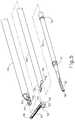
- FIG. 4depicts a partially exploded perspective view of the surgical instrument of FIG. 1 ;
- FIG. 5depicts an enlarged exploded perspective view of a distal portion of the shaft assembly and the end effector of the surgical instrument of FIG. 1 ;
- FIG. 6depicts a side elevational view of a distal portion of an inner tube of the shaft assembly of the surgical instrument of FIG. 1 ;
- FIG. 7depicts a perspective view of the ultrasonic blade and a distal portion of the shaft assembly of the surgical instrument of FIG. 1 , with the clamp arm hidden from view;
- FIG. 8depicts a top elevational view of the ultrasonic blade and distal portion of the shaft assembly of FIG. 7 ;
- FIG. 9depicts a sectional view of the ultrasonic blade of FIG. 7 , taken along section line 9 - 9 of FIG. 8 ;
- FIG. 10depicts a schematic sectional end view of the end effector of the surgical instrument of FIG. 1 , showing a clamp arm having a clamp pad and first and second electrode portions on either side of the clamp pad, indicating a lateral width of each electrode portion and a side gap distance between each electrode portion and a respective lateral side of the ultrasonic blade;
- FIG. 11depicts a bottom elevational view of an exemplary version of the end effector of FIG. 10 , the version including a clamp arm having first and second electrode portions that each maintain a uniform lateral width and a uniform side gap distance along a tissue treatment portion of the ultrasonic blade;
- FIG. 12depicts a bottom elevational view of another exemplary version of the end effector of FIG. 10 , the version including a clamp arm having first and second electrode portions that each maintain a uniform lateral width and a non-uniform side gap distance that increases distally;
- FIG. 13depicts a bottom elevational view of another exemplary version of the end effector of FIG. 10 , the version including a clamp arm having first and second electrode portions having non-uniform lateral widths that decrease distally, and non-uniform side gap distances that increase distally; and
- FIG. 14depicts a bottom elevational view of another exemplary version of the end effector of FIG. 10 , the version including a clamp arm having first and second electrode portions having distal ends that are separated from one another.
- proximal and distalare defined herein relative to a surgeon, or other operator, grasping a surgical instrument having a distal surgical end effector.
- proximalrefers to the position of an element arranged closer to the surgeon
- distalrefers to the position of an element arranged closer to the surgical end effector of the surgical instrument and further away from the surgeon.
- spatial termssuch as “upper,” “lower,” “vertical,” “horizontal,” or the like are used herein with reference to the drawings, it will be appreciated that such terms are used for exemplary description purposes only and are not intended to be limiting or absolute. In that regard, it will be understood that surgical instruments such as those disclosed herein may be used in a variety of orientations and positions not limited to those shown and described herein.
- FIG. 1depicts an exemplary surgical system ( 10 ) including a generator ( 12 ) and a surgical instrument ( 14 ).
- Surgical instrument ( 14 )is operatively coupled with the generator ( 12 ) via power cable ( 16 ).
- generator ( 12 )is operable to power surgical instrument ( 14 ) to deliver ultrasonic energy for cutting tissue, and electrosurgical bipolar RF energy (i.e., therapeutic levels of RF energy) for sealing tissue.
- generator ( 12 )is configured to power surgical instrument ( 14 ) to deliver ultrasonic energy and electrosurgical bipolar RF energy simultaneously.
- Surgical instrument ( 14 ) of the present examplecomprises a handle assembly ( 18 ), a shaft assembly ( 20 ) extending distally from the handle assembly ( 18 ), and an end effector ( 22 ) arranged at a distal end of the shaft assembly ( 20 ).
- Handle assembly ( 18 )comprises a body ( 24 ) including a pistol grip ( 26 ) and energy control buttons ( 28 , 30 ) configured to be manipulated by a surgeon.
- a trigger ( 32 )is coupled to a lower portion of body ( 24 ) and is pivotable toward and away from pistol grip ( 26 ) to selectively actuate end effector ( 22 ), as described in greater detail below.
- handle assembly ( 18 )may comprise a scissor grip configuration, for example.
- an ultrasonic transducer ( 34 )is housed internally within and supported by body ( 24 ). In other configurations, ultrasonic transducer ( 34 ) may be provided externally of body ( 24 ).
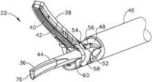
- end effector ( 22 )includes an ultrasonic blade ( 36 ) and a clamp arm ( 38 ) configured to selectively pivot toward and away from ultrasonic blade ( 36 ), for clamping tissue therebetween.
- Ultrasonic blade ( 36 )is acoustically coupled with ultrasonic transducer ( 34 ), which is configured to drive (i.e., vibrate) ultrasonic blade ( 36 ) at ultrasonic frequencies for cutting and/or sealing tissue positioned in contact with ultrasonic blade ( 36 ).
- Clamp arm ( 38 )is operatively coupled with trigger ( 32 ) such that clamp arm ( 38 ) is configured to pivot toward ultrasonic blade ( 36 ), to a closed position, in response to pivoting of trigger ( 32 ) toward pistol grip ( 26 ). Further, clamp arm ( 38 ) is configured to pivot away from ultrasonic blade ( 36 ), to an open position (see e.g., FIGS. 1-3 ), in response to pivoting of trigger ( 32 ) away from pistol grip ( 26 ).
- Various suitable ways in which clamp arm ( 38 ) may be coupled with trigger ( 32 )will be apparent to those of ordinary skill in the art in view of the teachings provided herein. In some versions, one or more resilient members may be incorporated to bias clamp arm ( 38 ) and/or trigger ( 32 ) toward the open position.
- a clamp pad ( 40 )is secured to and extends distally along a clamping side of clamp arm ( 38 ), facing ultrasonic blade ( 36 ).
- Clamp pad ( 40 )is configured to engage and clamp tissue against a corresponding tissue treatment portion of ultrasonic blade ( 36 ) when clamp arm ( 38 ) is actuated to its closed position.
- At least a clamping-side of clamp arm ( 38 )provides a first electrode ( 42 ), referred to herein as clamp arm electrode ( 42 ).
- at least a clamping-side of ultrasonic blade ( 36 )provides a second electrode ( 44 ), referred to herein as a blade electrode ( 44 ).
- electrodes ( 42 , 44 )are configured to apply electrosurgical bipolar RF energy, provided by generator ( 12 ), to tissue electrically coupled with electrodes ( 42 , 44 ).
- Clamp arm electrode ( 42 )may serve as an active electrode while blade electrode ( 44 ) serves as a return electrode, or vice-versa.
- Surgical instrument ( 14 )may be configured to apply the electrosurgical bipolar RF energy through electrodes ( 42 , 44 ) while vibrating ultrasonic blade ( 36 ) at an ultrasonic frequency, before vibrating ultrasonic blade ( 36 ) at an ultrasonic frequency, and/or after vibrating ultrasonic blade ( 36 ) at an ultrasonic frequency.
- shaft assembly ( 20 )extends along a longitudinal axis and includes an outer tube ( 46 ), an inner tube ( 48 ) received within outer tube ( 46 ), and an ultrasonic waveguide ( 50 ) supported within inner tube ( 48 ).
- clamp arm ( 38 )is coupled to distal ends of inner and outer tubes ( 46 , 48 ).
- clamp arm ( 38 )includes a pair of proximally extending clevis arms ( 52 ) that receive therebetween and pivotably couple to a distal end ( 54 ) of inner tube ( 48 ) with a pivot pin ( 56 ) received within through bores formed in clevis arms ( 52 ) and distal end ( 54 ) of inner tube ( 48 ).
- First and second clevis fingers ( 58 )depend downwardly from clevis arms ( 52 ) and pivotably couple to a distal end ( 60 ) of outer tube ( 46 ).
- each clevis finger ( 58 )includes a protrusion ( 62 ) that is rotatably received within a corresponding opening ( 64 ) formed in a sidewall of distal end ( 60 ) of outer tube ( 46 ).
- inner tube ( 48 )is longitudinally fixed relative to handle assembly ( 18 ), and outer tube ( 46 ) is configured to translate relative to inner tube ( 48 ) and handle assembly ( 18 ), along the longitudinal axis of shaft assembly ( 20 ).
- clamp arm ( 38 )pivots about pivot pin ( 56 ) toward its open position.
- clamp arm ( 38 )pivots in an opposite direction toward its closed position.
- a proximal end of outer tube ( 46 )is operatively coupled with trigger ( 32 ), for example via a linkage assembly, such that actuation of trigger ( 32 ) causes translation of outer tube ( 46 ) relative to inner tube ( 48 ), thereby opening or closing clamp arm ( 38 ).
- outer tube ( 46 )may be longitudinally fixed and inner tube ( 48 ) may be configured to translate for moving clamp arm ( 38 ) between its open and closed positions.
- Shaft assembly ( 20 ) and end effector ( 22 )are configured to rotate together about the longitudinal axis, relative to handle assembly ( 18 ).
- a retaining pin ( 66 ), shown in FIG. 4extends transversely through proximal portions of outer tube ( 46 ), inner tube ( 48 ), and waveguide ( 50 ) to thereby couple these components rotationally relative to one another.
- a rotation knob ( 68 )is provided at a proximal end portion of shaft assembly ( 20 ) to facilitate rotation of shaft assembly ( 20 ), and end effector ( 22 ), relative to handle assembly ( 18 ).
- Rotation knob ( 68 )is secured rotationally to shaft assembly ( 20 ) with retaining pin ( 66 ), which extends through a proximal collar of rotation knob ( 68 ). It will be appreciated that in other suitable configurations, rotation knob ( 68 ) may be omitted or substituted with alternative rotational actuation structures.
- Ultrasonic waveguide ( 50 )is acoustically coupled at its proximal end with ultrasonic transducer ( 34 ), for example by a threaded connection, and at its distal end with ultrasonic blade ( 36 ), as shown in FIG. 5 .
- Ultrasonic blade ( 36 )is shown formed integrally with waveguide ( 50 ) such that blade ( 36 ) extends distally, directly from the distal end of waveguide ( 50 ). In this manner, waveguide ( 50 ) acoustically couples ultrasonic transducer ( 34 ) with ultrasonic blade ( 36 ), and functions to communicate ultrasonic mechanical vibrations from transducer ( 34 ) to blade ( 36 ).
- ultrasonic transducer ( 34 ), waveguide ( 50 ), and ultrasonic blade ( 36 )together define acoustic assembly ( 100 ).
- ultrasonic blade ( 36 )may be positioned in direct contact with tissue, with or without assistive clamping force provided by clamp arm ( 38 ), to impart ultrasonic vibrational energy to the tissue and thereby cut and/or seal the tissue.
- blade ( 36 )may cut through tissue clamped between clamp arm ( 38 ) and a first treatment side ( 204 ) of blade ( 36 ), or blade ( 36 ) may cut through tissue positioned in contact with an oppositely disposed second treatment side ( 206 ) of blade ( 36 ), for example during a “back-cutting” movement.
- waveguide ( 50 )may amplify the ultrasonic vibrations delivered to blade ( 36 ). Further, waveguide ( 50 ) may include various features operable to control the gain of the vibrations, and/or features suitable to tune waveguide ( 50 ) to a selected resonant frequency. Additional exemplary features of ultrasonic blade ( 36 ) and waveguide ( 50 ) are described in greater detail below.
- Waveguide ( 50 )is supported within inner tube ( 48 ) by a plurality of nodal support elements ( 70 ) positioned along a length of waveguide ( 50 ), as shown in FIGS. 4 and 5 .
- nodal support elements ( 70 )are positioned longitudinally along waveguide ( 50 ) at locations corresponding to acoustic nodes defined by the resonant ultrasonic vibrations communicated through waveguide ( 50 ).
- Nodal support elements ( 70 )may provide structural support to waveguide ( 50 ), and acoustic isolation between waveguide ( 50 ) and inner and outer tubes ( 46 , 48 ) of shaft assembly ( 20 ).
- nodal support elements ( 70 )may comprise o-rings.
- Waveguide ( 50 )is supported at its distal-most acoustic node by a nodal support element in the form of an overmold member ( 72 ), shown in FIG. 5 .
- Waveguide ( 50 )is secured longitudinally and rotationally within shaft assembly ( 20 ) by retaining pin ( 66 ), which passes through a transverse through-bore ( 74 ) formed at a proximally arranged acoustic node of waveguide ( 50 ), such as the proximal-most acoustic node, for example.
- a distal tip ( 76 ) of ultrasonic blade ( 36 )is located at a position corresponding to an anti-node associated with the resonant ultrasonic vibrations communicated through waveguide ( 50 ).
- Such a configurationenables the acoustic assembly ( 100 ) of instrument ( 14 ) to be tuned to a preferred resonant frequency f 0 when ultrasonic blade ( 36 ) is not loaded by tissue.
- ultrasonic transducer ( 34 )When ultrasonic transducer ( 34 ) is energized by generator ( 12 ) to transmit mechanical vibrations through waveguide ( 50 ) to blade ( 36 ), distal tip ( 76 ) of blade ( 36 ) is caused to oscillate longitudinally in the range of approximately 20 to 120 microns peak-to-peak, for example, and in some instances in the range of approximately 20 to 50 microns, at a predetermined vibratory frequency f 0 of approximately 50 kHz, for example.
- the ultrasonic oscillation of blade ( 36 )may simultaneously sever the tissue and denature the proteins in adjacent tissue cells, thereby providing a coagulative effect with minimal thermal spread.
- distal end ( 54 ) of inner tube ( 48 )may be offset radially outwardly relative to a remaining proximal portion of inner tube ( 48 ).
- This configurationenables pivot pin bore ( 78 ), which receives clamp arm pivot pin ( 56 ), to be spaced further away from the longitudinal axis of shaft assembly ( 20 ) than if distal end ( 54 ) where formed flush with the remaining proximal portion of inner tube ( 48 ).
- thisprovides increased clearance between proximal portions of clamp arm electrode ( 42 ) and blade electrode ( 44 ), thereby mitigating risk of undesired “shorting” between electrodes ( 42 , 44 ) and their corresponding active and return electrical paths, for example during back-cutting when ultrasonic blade ( 36 ) flexes toward clamp arm ( 38 ) and pivot pin ( 56 ) in response to normal force exerted on blade ( 36 ) by tissue.
- ultrasonic blade ( 36 )may tend to deflect slightly away from the longitudinal axis of shaft assembly ( 20 ), toward pin ( 56 ).
- distal end ( 54 )By having pivot pin bore ( 78 ) spaced further away from the longitudinal axis than pivot pin bore ( 78 ) otherwise would be in the absence of the radial offset provided by distal end ( 54 ) of the present example, distal end ( 54 ) provides additional lateral clearance between pivot pin ( 56 ) and ultrasonic blade ( 36 ), thereby reducing or eliminating the risk of contact between ultrasonic blade ( 36 ) and pivot pin ( 56 ) when ultrasonic blade ( 36 ) deflects laterally during back-cutting operations.
- the additional clearanceprevents mechanical damage that might otherwise result from contact between ultrasonic blade ( 36 ) and pivot pin ( 56 ) when ultrasonic blade ( 36 ) is vibrating ultrasonically.
- FIGS. 7-9show additional details of ultrasonic blade ( 36 ) of surgical instrument ( 14 ).
- Ultrasonic blade ( 36 )includes a tissue treatment portion that extends distally beyond inner tube and outer tube distal ends ( 54 , 60 ), and terminates at distal tip ( 76 ) having filleted edges.
- Tissue treatment portion of blade ( 36 )is configured to contact and treat tissue with ultrasonic energy received through ultrasonic waveguide ( 50 ).
- the tissue treatment portion of blade ( 36 )includes a proximal linear blade region ( 202 ) and a distal curved blade region ( 204 ) extending distally from linear blade region ( 202 ).
- Linear blade region ( 202 )extends parallel to the longitudinal axis defined by shaft assembly ( 20 ), along which waveguide ( 50 ) extends.
- Curved blade region ( 204 )extends along a curved path that deflects laterally away from the longitudinal axis in a distal direction. As shown best in FIG. 8 , a lateral dimension of curved blade region ( 204 ) tapers distally toward distal tip ( 76 ).
- clamp arm ( 38 )may be shaped similarly to treatment portion of ultrasonic blade ( 36 ) in that clamp arm ( 38 ) includes a proximal linear clamp portion and a distal curved clamp portion. In alternative configurations, ultrasonic blade ( 36 ) and clamp arm ( 38 ) may be entirely linear and extend parallel to the longitudinal axis.
- Tissue treatment portion of ultrasonic blade ( 36 )includes an upper primary treatment side ( 206 ) that faces clamp arm ( 38 ) (hidden from view) and is configured to compress tissue against clamp arm ( 38 ).
- Tissue treatment portionfurther includes a lower secondary treatment side having a cutting edge ( 208 ), arranged opposite of primary treatment side ( 206 ) and facing away from clamp arm ( 38 ).
- Cutting edge ( 208 )is configured to cut tissue during back-cutting procedures.
- First and second lateral blade sides ( 210 , 212 )extend between primary treatment side ( 206 ) and cutting edge ( 208 ). As best shown in the sectional view of FIG. 9 , primary treatment side ( 206 ) is convexly rounded.
- each of first and second lateral sides ( 210 , 212 )includes a sweeping flat side surface ( 214 ) that extends distally through a distal portion of linear blade region ( 202 ) and an entirety of curved blade region ( 204 ), along the curved path thereof.
- sweeping flat side surfaces ( 214 )depend downwardly from the rounded treatment surface of primary treatment side ( 206 ), and define a cross-section of ultrasonic blade ( 36 ) having lateral side edges that are generally parallel to one another.
- a blade height of ultrasonic blade ( 36 ) at a selected longitudinal locationis defined by a maximum transverse distance measured between primary treatment side ( 206 ) and cutting edge ( 208 ) at the selected location.
- a blade width of ultrasonic blade ( 36 ) at a selected longitudinal locationis defined by a maximum transverse distance measured between first and second lateral sides ( 210 , 212 ) at the selected location.
- curved blade region ( 204 )is shaped such that at various longitudinal locations therealong, including at blade tip ( 76 ), the blade height is greater than the corresponding blade width. In other configurations, the blade height may be less than or equal to the blade width.
- FIG. 10shows a schematic sectional end view of a tissue treatment portion of end effector ( 22 ) of surgical instrument ( 14 ), including ultrasonic blade ( 36 ) and clamp arm ( 38 ) having clamp pad ( 40 ).
- Clamp pad ( 40 )extends distally along a centerline region of the clamping side of clamp arm ( 38 ) and provides clamp arm electrode ( 42 ).
- Clamp arm electrode ( 42 )includes a first electrode side portion ( 280 ) extending distally along a first lateral side of clamp pad ( 40 ), and a second electrode side portion ( 282 ) extending distally along an opposed second lateral side of clamp pad ( 40 ). As shown in FIG.
- each clamp arm electrode side portion ( 280 , 282 )is formed with a lateral electrode width (W) measured from an outer lateral edge of the electrode side portion ( 280 , 282 ) to an inner lateral edge of the electrode side portion ( 280 , 282 ), shown abutting the corresponding lateral side of clamp pad ( 40 ).
- Clamp pad ( 40 )is formed with a lateral pad width that is greater than a lateral width of ultrasonic blade ( 36 ), so as to define a lateral gap distance (G 1 ) between an inner lateral edge of each clamp arm electrode side portion ( 280 , 282 ) and the corresponding lateral side ( 210 , 212 ) of blade ( 36 ).
- Clamp pad ( 40 )protrudes beyond electrode side portions ( 280 , 282 ) in a direction toward primary treatment side ( 266 ) of blade ( 36 ).
- This configurationdefines a vertical gap distance (G 2 ) between each electrode side portion ( 280 , 282 ) and a clamping surface of clamp pad ( 40 ) and thus primary treatment side ( 266 ) of blade ( 36 ).
- Optimal sizing of lateral electrode width (W)provides adequate electrode surface area for delivery of bipolar RF energy sufficient to seal tissue, while preventing unwanted electrical sparking or arcing caused by an electrode width (W) that is too small.
- Optimal sizing of gap distances (G 1 , G 2 )enables peak efficiency of end effector ( 22 ). For instance, optimal sizing of gap distances (G 1 , G 2 ) prevents unwanted electrical shorting between ultrasonic blade ( 36 ) and clamp arm ( 38 ) caused by gap distances (G 1 , G 2 ) that are too small, and further prevents unwanted electrical sparking or arcing and resulting inefficient transfer of RF energy caused by gap distances (G 1 , G 2 ) that are too large.
- lateral electrode width (W) of each clamp arm electrode side portion ( 280 , 282 )may be in the range of approximately 0.007 inches to approximately 0.018 inches, such as approximately 0.018 inches, for instance.
- Lateral gap distance (G 1 ) corresponding to each electrode side portion ( 280 , 282 )may be in the range of approximately 0.002 inches to approximately 0.012 inches, such as approximately 0.007 inches or approximately 0.012 inches, for instance.
- vertical gap distances (G 2 ) corresponding to electrode side portions ( 280 , 282 )are greater than 0 and may be uniform and equal to one another along an entire length of electrode side portions ( 280 , 290 ).
- clamp arm ( 38 ) and its dimensional configurationsare described below, each of which is configured to function in a manner similar to clamp arm ( 38 ), and is suitable for use with surgical instrument ( 14 ). Furthermore, lateral electrode widths (W) and gap distances (G 1 , G 2 ) of the additional clamp arm configurations described below may fall within the exemplary ranges described above. Persons skilled in the art will appreciate that various additional versions of clamp arm ( 38 ), incorporating any one or more of the exemplary clamp arm electrode features of the clamp arms described below, may be used in combination with surgical instrument ( 14 ).
- FIG. 11shows an end effector ( 290 ) including ultrasonic blade ( 36 ) and a clamp arm ( 292 ) according to a first exemplary version of clamp arm ( 38 ) of FIG. 10 .
- Clamp arm ( 292 )is similar to clamp arm ( 38 ) in that clamp arm ( 292 ) includes a centrally positioned clamp pad ( 294 ) and first and second clamp arm electrode side portions ( 296 , 298 ) extending distally along respective lateral sides of clamp pad ( 294 ). Distal ends of clamp arm electrode side portions ( 296 , 298 ) are joined together by a distal electrode bridge portion ( 299 ).
- the lateral electrode width (W) of each electrode side portion ( 296 , 298 )is uniform and equal to the other along an entire length of the treatment portion of ultrasonic blade ( 36 ).
- the lateral gap distance (G 1 ) corresponding to each electrode side portion ( 296 , 298 )is uniform and equal to the other along an entire length of the tissue treatment portion of ultrasonic blade ( 36 ).
- the lateral electrode widths W and the lateral gap distances Gmay fall within the ranges described above.
- FIG. 12shows an end effector ( 300 ) including ultrasonic blade ( 36 ) and a clamp arm ( 302 ) according to a second exemplary version of clamp arm ( 38 ) of FIG. 10 .
- Clamp arm ( 302 )is similar to clamp arm ( 292 ) of FIG. 11 in that clamp arm ( 302 ) includes a centrally positioned clamp pad ( 304 ) and first and second clamp arm electrode side portions ( 306 , 308 ) extending distally along respective lateral sides of clamp pad ( 304 ) and joined at their distal ends by an electrode bridge portion ( 309 ).
- Clamp arm ( 302 )is further similar to clamp arm ( 292 ) in that the lateral electrode width (W) of each electrode side portion ( 306 , 308 ) is uniform and equal to the other along an entire length of the tissue treatment portion of ultrasonic blade ( 36 ).
- Clamp arm ( 302 )differs from clamp arm ( 292 ) in that lateral gap distance (G 1 ) for each electrode side portion ( 306 , 308 ) is non-uniform along the length of tissue treatment portion of blade ( 36 ). Specifically, lateral gap distances (G 1 ) flare, or increase, distally along a distal portion of curved region ( 204 ) of blade ( 36 ). In the present example, lateral gap distance (G 1 ) for electrode side portion ( 308 ) increases distally at a greater rate than lateral gap distance (G 1 ) for electrode side portion ( 306 ).
- lateral gap distances (G 1 ) for electrode side portions ( 306 , 308 )are not equal to one another throughout the distal portion of curved region ( 204 ) of blade ( 36 ).
- lateral gap distance (G 1 ) for electrode side portion ( 308 )is larger than lateral gap distance (G 1 ) for electrode side portion ( 306 ).
- lateral gap distances (G 1 ) for electrode side portions ( 306 , 308 )may increase distally at the same rate such that gap distances (G 1 ) remain equal to one another throughout curved blade region ( 204 ).
- clamp arm ( 302 )may be achieved by providing clamp pad ( 304 ) with a width that flares, or increases, laterally outward through the distal portion of curved blade region ( 204 ).
- Wlateral electrode width
- the lateral width of clamp arm ( 302 )increases, or flares, distally simultaneously with the lateral width of clamp pad ( 304 ).
- FIG. 13shows an end effector ( 310 ) including ultrasonic blade ( 36 ) and a clamp arm ( 312 ) according to a third exemplary version of clamp arm ( 38 ) of FIG. 10 .
- Clamp arm ( 312 )is similar to clamp arm ( 302 ) of FIG. 12 in that clamp arm ( 312 ) includes a centrally positioned clamp pad ( 314 ) and first and second clamp arm electrode side portions ( 316 , 318 ) extending distally along respective lateral sides of clamp pad ( 314 ) and joined at their distal ends by an electrode bridge portion ( 319 ).
- Clamp arm ( 312 )is further similar to clamp arm ( 302 ) in that lateral gap distance (G 1 ) for each electrode side portion ( 316 , 318 ) increases distally along a distal portion of curved blade region ( 204 ), and gap distances (G 1 ) are not equal to one another at all longitudinal locations throughout curved blade region ( 204 ).
- Clamp arm ( 312 )differs from clamp arm ( 302 ) in that the lateral electrode width (W) of each electrode side portion ( 316 , 318 ) is non-uniform along the length of the tissue treatment portion of blade ( 36 ). Specifically, the lateral electrode widths (W) taper, or decrease, distally along the distal portion of curved blade region ( 204 ). In other words, as the lateral gap distances (G 1 ) increase, the lateral electrode widths (W) decrease. The rates of increase and decrease may be similar to one another. Additionally, the lateral electrode widths (W) of electrode side portions ( 316 , 318 ) may be substantially equal to each other at any given longitudinal location along clamp arm ( 312 ).
- clamp arm ( 302 )deliver concentrated levels of bipolar RF energy at the clamp arm sections having increased gap distances (G 1 ). This enables effective delivery of electrosurgical bipolar RF energy to tissue at the larger gap sections, which sections accommodate greater degrees of lateral deflection of ultrasonic blade ( 36 ) as described above, without requiring that a lateral width of clamp arm ( 312 ) flare outward like that of clamp arm ( 302 ) of FIG. 12 . Accordingly, clamp arm ( 312 ) may generally provide the same performance benefits as clamp arm ( 302 ), while maintaining a slimmer profile.
- FIG. 14shows an end effector ( 320 ) including ultrasonic blade ( 36 ) and a clamp arm ( 322 ) according to a fourth exemplary version of clamp arm ( 38 ) of FIG. 10 .
- Clamp arm ( 322 )is similar to clamp arms ( 292 , 302 , 312 ) described above in that clamp arm ( 322 ) includes a centrally positioned clamp pad ( 324 ) and first and second clamp arm electrode side portions ( 326 , 328 ) extending distally along respective lateral sides of clamp pad ( 324 ). Additionally, lateral electrode width (W) of each electrode side portion ( 326 , 328 ) is uniform and equal to the other along an entire length of the tissue treatment portion of ultrasonic blade ( 36 ).
- Clamp arm ( 322 )differs from clamp arms ( 292 , 302 , 312 ) in that clamp arm ( 322 ) omits a distal electrode bridge portion joining distal ends ( 327 , 329 ) of electrode side portions ( 326 , 328 ). Rather, in the present example, electrode distal ends ( 327 , 329 ) are laterally separated from one another by clamp pad ( 324 ), which extends to a distal tip of clamp arm ( 322 ). Additionally, electrode distal ends ( 327 , 329 ) align with distal blade tip ( 76 ), though it will be appreciated that distal ends ( 327 , 329 ) may terminate proximally or distally of blade tip ( 76 ) in other examples.
- clamp arms ( 292 , 302 , 312 ) described abovemay be provided in which distal electrode bridge portions ( 299 , 309 , 319 ) are omitted to provide electrode distal ends similar to distal ends ( 327 , 329 ) of clamp arm ( 322 ).
- Each clamp arm ( 292 , 302 , 312 , 322 ) as described abovehas first and second electrode side portions that are equal in width (W) to one another along an entire length of the electrode side portions.
- alternative versions of clamp arms ( 292 , 302 , 312 , 322 )may have electrode side portions that are unequal in width (W) along one or more longitudinally extending portions thereof, for example along portions corresponding to curved blade region ( 204 ).
- Such variation in electrode widths (W)may be provided to accommodate differences in performance exhibited by blade ( 36 ) and/or clamp arm ( 292 , 302 , 312 , 322 ) between their concave curved lateral sides, corresponding to first lateral blade side ( 210 ), and their respective convex curved lateral sides, corresponding to second lateral blade side ( 212 ).
- the concave curved lateral sides of blade ( 36 ) and clamp arm ( 292 , 302 , 312 , 322 )may provide a first degree of cutting and sealing treatment to tissue, while the convex curved lateral sides of blade ( 36 ) and clamp arm ( 292 , 302 , 312 , 322 ) may provide a second degree of cutting and sealing treatment to tissue.
- a surgical instrumentcomprising: (a) an ultrasonic transducer; (b) a shaft extending distally relative to the ultrasonic transducer; and (c) an end effector arranged at a distal end of the shaft, wherein the end effector comprises: (i) an ultrasonic blade configured to be driven by the ultrasonic transducer with ultrasonic energy, wherein the ultrasonic blade comprises: (A) an upper treatment side, (B) a lower treatment side arranged opposite of the upper treatment side, (C) a first lateral side, and (D) a second lateral side arranged opposite of the first lateral side, and (ii) a clamp arm movable relative to the ultrasonic blade for clamping tissue therebetween, wherein the clamp arm provides an RF electrode operable to seal tissue with RF energy, wherein the RF electrode comprises: (A) a first electrode side portion, wherein the first electrode side portion is spaced laterally outward from the first lateral side of the ultrasonic blade by a first lateral gap distance
- Example 1The surgical instrument of Example 1, wherein the end effector further comprises a clamp pad coupled to the clamp arm, wherein the first electrode side portion extends along a first lateral side of the clamp pad, wherein the second electrode side portion extends along a second lateral side of the clamp pad.
- first lateral gap distanceis equal to the second lateral gap distance along a curved distal portion of the ultrasonic blade.
- each of the first lateral gap distance and the second lateral gap distanceis in the range of 0.002 inches to 0.012 inches along a curved distal portion of the ultrasonic blade.
- a lateral width of at least one of the first electrode side portion or the second electrode side portionis uniform along a length of at least a distal portion of the clamp arm.
- a lateral width of at least one of the first electrode side portion or the second electrode side portionis non-uniform along a length of at least a distal portion of the clamp arm.
- Example 8The surgical instrument of Example 8, wherein the lateral width of at least one of the first electrode side portion or the second electrode side portion increases distally.
- a lateral width of each of the first electrode side portion and the second electrode side portionis in the range of 0.007 inches to 0.018 inches along a length of at least a distal portion of the clamp arm.
- the RF electrodeextends distally beyond a distal tip of the ultrasonic blade and defines an electrode bridge portion that electrically couples a distal end of the first electrode side portion with a distal end of the second electrode side portion.
- the ultrasonic bladeincludes a linear proximal portion and a curved distal portion, wherein the first and second electrode side portions extend alongside the curved distal portion.
- the RF electrodecomprises a first RF electrode, wherein the ultrasonic blade provides a second RF electrode, wherein the first and second RF electrodes are operable to seal tissue with bipolar RF energy.
- a surgical instrumentcomprising: (a) an ultrasonic transducer; (b) a shaft extending distally relative to the ultrasonic transducer; and (c) an end effector arranged at a distal end of the shaft, wherein the end effector comprises: (i) an ultrasonic blade configured to be driven by the ultrasonic transducer with ultrasonic energy, wherein the ultrasonic blade comprises: (A) an upper treatment side, (B) a lower treatment side arranged opposite of the upper treatment side, (C) a first lateral side, and (D) a second lateral side arranged opposite of the first lateral side, and (ii) a clamp arm movable relative to the ultrasonic blade for clamping tissue therebetween, wherein the clamp arm provides an RF electrode operable to seal tissue with RF energy, wherein the RF electrode comprises: (A) a first electrode side portion, wherein the first electrode side portion has a first width and is spaced laterally outward from the first lateral side of the ultrasonic blade by
- a surgical instrumentcomprising: (a) an ultrasonic transducer; (b) a shaft extending distally relative to the ultrasonic transducer; and (c) an end effector arranged at a distal end of the shaft, wherein the end effector comprises: (i) an ultrasonic blade configured to be driven by the ultrasonic transducer with ultrasonic energy, wherein the ultrasonic blade comprises: (A) a linear proximal blade portion, (B) a curved distal blade portion, (C) a first lateral side, and (D) a second lateral side arranged opposite of the first lateral side, and (ii) a clamp arm movable relative to the ultrasonic blade for clamping tissue therebetween, wherein the clamp arm provides an RF electrode operable to seal tissue with RF energy, wherein the RF electrode comprises: (A) a first electrode side portion, wherein the first electrode side portion is spaced laterally outward from the first lateral side of the ultrasonic blade by a first lateral gap distance
- a lateral width of at least one of the first electrode side portion or the second electrode side portionis in the range of 0.007 inches to 0.018 inches along the curved distal blade portion.
- any one or more of the teachings, expressions, embodiments, examples, etc. described hereinmay be combined with any one or more of the teachings, expressions, embodiments, examples, etc. described in U.S. patent application Ser. No. 15/967,740, entitled “Combination Ultrasonic and Electrosurgical Instrument Having Electrical Circuits With Shared Return Path,” filed on May 1, 2018, published as U.S. Pub. No. 2018/0333177 on Nov. 22, 2018; U.S. patent application Ser. No. 15/967,746, entitled “Combination Ultrasonic and Electrosurgical Instrument Having Slip Ring Electrical Contact Assembly,” filed on May 1, 2018, published as U.S. Pub. No. 2018/0333178 on Nov. 22, 2018, issued as U.S. Pat. No.
- any one or more of the teachings, expressions, embodiments, examples, etc. described hereinmay be combined with any one or more of the teachings, expressions, embodiments, examples, etc. described in U.S. patent application Ser. No. 15/967,758, entitled “Combination Ultrasonic and Electrosurgical Instrument with Clamp Arm Position Input and Method for Identifying Tissue State,” filed on May 1, 2018, published as U.S. Pub. No. 2018/0333182 on Nov. 22, 2018; U.S. patent application Ser. No. 15/967,763, entitled “Combination Ultrasonic and Electrosurgical Instrument with Adjustable Energy Modalities and Method for Sealing Tissue and Inhibiting Tissue Resection,” filed on May 1, 2018, published as U.S. Pub. No.
- Versions of the devices described abovemay be designed to be disposed of after a single use, or they can be designed to be used multiple times. Versions may, in either or both cases, be reconditioned for reuse after at least one use. Reconditioning may include any combination of the steps of disassembly of the device, followed by cleaning or replacement of particular pieces, and subsequent reassembly. In particular, some versions of the device may be disassembled, and any number of the particular pieces or parts of the device may be selectively replaced or removed in any combination. Upon cleaning and/or replacement of particular parts, some versions of the device may be reassembled for subsequent use either at a reconditioning facility, or by a user immediately prior to a procedure.
- reconditioning of a devicemay utilize a variety of techniques for disassembly, cleaning/replacement, and reassembly. Use of such techniques, and the resulting reconditioned device, are all within the scope of the present application.
- versions described hereinmay be sterilized before and/or after a procedure.
- the deviceis placed in a closed and sealed container, such as a plastic or TYVEK bag.
- the container and devicemay then be placed in a field of radiation that can penetrate the container, such as gamma radiation, x-rays, or high-energy electrons.
- the radiationmay kill bacteria on the device and in the container.
- the sterilized devicemay then be stored in the sterile container for later use.
- a devicemay also be sterilized using any other technique known in the art, including but not limited to beta or gamma radiation, ethylene oxide, or steam.
Landscapes
- Health & Medical Sciences (AREA)
- Surgery (AREA)
- Life Sciences & Earth Sciences (AREA)
- Engineering & Computer Science (AREA)
- Heart & Thoracic Surgery (AREA)
- Veterinary Medicine (AREA)
- Nuclear Medicine, Radiotherapy & Molecular Imaging (AREA)
- Biomedical Technology (AREA)
- Public Health (AREA)
- Medical Informatics (AREA)
- Molecular Biology (AREA)
- Animal Behavior & Ethology (AREA)
- General Health & Medical Sciences (AREA)
- Otolaryngology (AREA)
- Physics & Mathematics (AREA)
- Plasma & Fusion (AREA)
- Dentistry (AREA)
- Mechanical Engineering (AREA)
- Surgical Instruments (AREA)
Abstract
Description
Claims (20)
Priority Applications (8)
| Application Number | Priority Date | Filing Date | Title |
|---|---|---|---|
| US15/967,753US11058472B2 (en) | 2017-05-22 | 2018-05-01 | Combination ultrasonic and electrosurgical instrument having clamp arm electrode |
| JP2019564481AJP7150751B2 (en) | 2017-05-22 | 2018-05-21 | Combined ultrasonic and electrosurgical instrument with clamp arm electrodes |
| CN201880033752.4ACN110662505A (en) | 2017-05-22 | 2018-05-21 | Combined Ultrasound and Electrosurgical Instrument with Gripper Arm Electrodes |
| PCT/US2018/033608WO2018217601A1 (en) | 2017-05-22 | 2018-05-21 | Combination ultrasonic and electrosurgical instrument having clamp arm electrode |
| BR112019024361ABR112019024361A2 (en) | 2017-05-22 | 2018-05-21 | combined electrosurgical and ultrasonic instrument with clamping arm electrode |
| CN202510469791.0ACN120284403A (en) | 2017-05-22 | 2018-05-21 | Combined ultrasonic and electrosurgical instrument with clamping arm electrode |
| MX2019013883AMX2019013883A (en) | 2017-05-22 | 2018-05-21 | Combination ultrasonic and electrosurgical instrument having clamp arm electrode. |
| EP18769836.0AEP3634285B1 (en) | 2017-05-22 | 2018-05-21 | Combination ultrasonic and electrosurgical instrument having clamp arm electrode |
Applications Claiming Priority (2)
| Application Number | Priority Date | Filing Date | Title |
|---|---|---|---|
| US201762509351P | 2017-05-22 | 2017-05-22 | |
| US15/967,753US11058472B2 (en) | 2017-05-22 | 2018-05-01 | Combination ultrasonic and electrosurgical instrument having clamp arm electrode |
Publications (2)
| Publication Number | Publication Date |
|---|---|
| US20180333181A1 US20180333181A1 (en) | 2018-11-22 |
| US11058472B2true US11058472B2 (en) | 2021-07-13 |
Family
ID=62620977
Family Applications (12)
| Application Number | Title | Priority Date | Filing Date |
|---|---|---|---|
| US15/967,753Active2039-05-24US11058472B2 (en) | 2017-05-22 | 2018-05-01 | Combination ultrasonic and electrosurgical instrument having clamp arm electrode |
| US15/967,761Active2040-07-17US11304741B2 (en) | 2017-05-22 | 2018-05-01 | Combination ultrasonic and electrosurgical system having generator filter circuitry |
| US15/967,751Active2039-07-29US11033316B2 (en) | 2017-05-22 | 2018-05-01 | Combination ultrasonic and electrosurgical instrument having curved ultrasonic blade |
| US15/967,740Active2040-01-05US11234750B2 (en) | 2017-05-22 | 2018-05-01 | Combination ultrasonic and electrosurgical instrument having electrical circuits with shared return path |
| US15/967,764Active2039-12-07US11129661B2 (en) | 2017-05-22 | 2018-05-01 | Combination ultrasonic and electrosurgical system having EEPROM and ASIC components |
| US15/967,747Active2039-05-23US10945779B2 (en) | 2017-05-22 | 2018-05-01 | Combination ultrasonic and electrosurgical instrument having electrically insulating features |
| US15/967,759Active2039-10-20US11051866B2 (en) | 2017-05-22 | 2018-05-01 | Combination ultrasonic and electrosurgical instrument having ultrasonic waveguide with distal overmold member |
| US15/967,746Active2039-05-23US10945778B2 (en) | 2017-05-22 | 2018-05-01 | Combination ultrasonic and electrosurgical instrument having slip ring electrical contact assembly |
| US17/314,691Active2040-02-10US12232791B2 (en) | 2017-05-22 | 2021-05-07 | Combination ultrasonic and electrosurgical instrument having curved ultrasonic blade |
| US17/337,885Active2040-06-07US12213717B2 (en) | 2017-05-22 | 2021-06-03 | Combination ultrasonic and electrosurgical instrument having electrical circuits with shared return path |
| US18/999,350PendingUS20250127550A1 (en) | 2017-05-22 | 2024-12-23 | Combination ultrasonic and electrosurgical instrument having electrical circuits with shared return path |
| US19/034,841PendingUS20250160922A1 (en) | 2017-05-22 | 2025-01-23 | Combination ultrasonic and electrosurgical instrument having curved ultrasonic blade |
Family Applications After (11)
| Application Number | Title | Priority Date | Filing Date |
|---|---|---|---|
| US15/967,761Active2040-07-17US11304741B2 (en) | 2017-05-22 | 2018-05-01 | Combination ultrasonic and electrosurgical system having generator filter circuitry |
| US15/967,751Active2039-07-29US11033316B2 (en) | 2017-05-22 | 2018-05-01 | Combination ultrasonic and electrosurgical instrument having curved ultrasonic blade |
| US15/967,740Active2040-01-05US11234750B2 (en) | 2017-05-22 | 2018-05-01 | Combination ultrasonic and electrosurgical instrument having electrical circuits with shared return path |
| US15/967,764Active2039-12-07US11129661B2 (en) | 2017-05-22 | 2018-05-01 | Combination ultrasonic and electrosurgical system having EEPROM and ASIC components |
| US15/967,747Active2039-05-23US10945779B2 (en) | 2017-05-22 | 2018-05-01 | Combination ultrasonic and electrosurgical instrument having electrically insulating features |
| US15/967,759Active2039-10-20US11051866B2 (en) | 2017-05-22 | 2018-05-01 | Combination ultrasonic and electrosurgical instrument having ultrasonic waveguide with distal overmold member |
| US15/967,746Active2039-05-23US10945778B2 (en) | 2017-05-22 | 2018-05-01 | Combination ultrasonic and electrosurgical instrument having slip ring electrical contact assembly |
| US17/314,691Active2040-02-10US12232791B2 (en) | 2017-05-22 | 2021-05-07 | Combination ultrasonic and electrosurgical instrument having curved ultrasonic blade |
| US17/337,885Active2040-06-07US12213717B2 (en) | 2017-05-22 | 2021-06-03 | Combination ultrasonic and electrosurgical instrument having electrical circuits with shared return path |
| US18/999,350PendingUS20250127550A1 (en) | 2017-05-22 | 2024-12-23 | Combination ultrasonic and electrosurgical instrument having electrical circuits with shared return path |
| US19/034,841PendingUS20250160922A1 (en) | 2017-05-22 | 2025-01-23 | Combination ultrasonic and electrosurgical instrument having curved ultrasonic blade |
Country Status (9)
| Country | Link |
|---|---|
| US (12) | US11058472B2 (en) |
| EP (10) | EP3629952B8 (en) |
| JP (9) | JP2020520723A (en) |
| CN (9) | CN110650696A (en) |
| BR (3) | BR112019024361A2 (en) |
| GB (2) | GB2608896B (en) |
| MX (8) | MX2019013908A (en) |
| PL (1) | PL3634274T3 (en) |
| WO (8) | WO2018217601A1 (en) |
Cited By (4)
| Publication number | Priority date | Publication date | Assignee | Title |
|---|---|---|---|---|
| USD938588S1 (en)* | 2019-01-25 | 2021-12-14 | Karl Storz Se & Co. Kg | Shaft attachable medical instrument |
| USD951444S1 (en)* | 2018-11-15 | 2022-05-10 | Cilag Gmbh International | Bipolar electrosurgical jaws |
| USD966513S1 (en)* | 2019-01-25 | 2022-10-11 | Karl Storz Se & Co. Kg | Shaft attachable medical instrument |
| US11737804B2 (en) | 2017-05-22 | 2023-08-29 | Cilag Gmbh International | Combination ultrasonic and electrosurgical instrument with adjustable energy modalities and method for limiting blade temperature |
Families Citing this family (57)
| Publication number | Priority date | Publication date | Assignee | Title |
|---|---|---|---|---|
| US11090104B2 (en) | 2009-10-09 | 2021-08-17 | Cilag Gmbh International | Surgical generator for ultrasonic and electrosurgical devices |
| US9408622B2 (en) | 2012-06-29 | 2016-08-09 | Ethicon Endo-Surgery, Llc | Surgical instruments with articulating shafts |
| US10194973B2 (en) | 2015-09-30 | 2019-02-05 | Ethicon Llc | Generator for digitally generating electrical signal waveforms for electrosurgical and ultrasonic surgical instruments |
| US11051840B2 (en) | 2016-01-15 | 2021-07-06 | Ethicon Llc | Modular battery powered handheld surgical instrument with reusable asymmetric handle housing |
| US11129670B2 (en) | 2016-01-15 | 2021-09-28 | Cilag Gmbh International | Modular battery powered handheld surgical instrument with selective application of energy based on button displacement, intensity, or local tissue characterization |
| US11229471B2 (en) | 2016-01-15 | 2022-01-25 | Cilag Gmbh International | Modular battery powered handheld surgical instrument with selective application of energy based on tissue characterization |
| US12193698B2 (en) | 2016-01-15 | 2025-01-14 | Cilag Gmbh International | Method for self-diagnosing operation of a control switch in a surgical instrument system |
| US11266430B2 (en) | 2016-11-29 | 2022-03-08 | Cilag Gmbh International | End effector control and calibration |
| US11058472B2 (en) | 2017-05-22 | 2021-07-13 | Cilag Gmbh International | Combination ultrasonic and electrosurgical instrument having clamp arm electrode |
| USD882782S1 (en) | 2018-02-21 | 2020-04-28 | Ethicon Llc | Three dimensional adjunct |
| US12351855B2 (en) | 2019-01-30 | 2025-07-08 | Arizona Board Of Regents On Behalf Of Arizona State University | Bioelectronic circuits, systems and methods for preparing and using them |
| AU2020253238B2 (en) | 2019-03-29 | 2025-03-06 | Gyrus Acmi, Inc. D/B/A Olympus Surgical Technologies America | Forceps motion transfer assembly |
| CN110151258B (en)* | 2019-05-01 | 2024-07-30 | 杭州康基医疗器械有限公司 | Support system for ultrasonic waveguide |
| CN110403672B (en)* | 2019-05-01 | 2024-04-19 | 杭州康基医疗器械有限公司 | Ultrasonic medical surgical instrument |
| CN110123416B (en)* | 2019-05-01 | 2024-05-07 | 杭州康基医疗器械有限公司 | Floating support structure of ultrasonic transducer |
| US12023085B2 (en) | 2019-08-29 | 2024-07-02 | Covidien Lp | Ultrasonic systems and methods with tissue resistance sensing |
| US11490890B2 (en) | 2019-09-16 | 2022-11-08 | Cilag Gmbh International | Compressible non-fibrous adjuncts |
| GB2594438A (en)* | 2019-12-05 | 2021-11-03 | Creo Medical Ltd | Electrosurgical instrument, generator and apparatus |
| US12343063B2 (en) | 2019-12-30 | 2025-07-01 | Cilag Gmbh International | Multi-layer clamp arm pad for enhanced versatility and performance of a surgical device |
| US12082808B2 (en) | 2019-12-30 | 2024-09-10 | Cilag Gmbh International | Surgical instrument comprising a control system responsive to software configurations |
| US12262937B2 (en) | 2019-12-30 | 2025-04-01 | Cilag Gmbh International | User interface for surgical instrument with combination energy modality end-effector |
| US12336747B2 (en) | 2019-12-30 | 2025-06-24 | Cilag Gmbh International | Method of operating a combination ultrasonic / bipolar RF surgical device with a combination energy modality end-effector |
| US11986201B2 (en) | 2019-12-30 | 2024-05-21 | Cilag Gmbh International | Method for operating a surgical instrument |
| US12114912B2 (en) | 2019-12-30 | 2024-10-15 | Cilag Gmbh International | Non-biased deflectable electrode to minimize contact between ultrasonic blade and electrode |
| US11944366B2 (en) | 2019-12-30 | 2024-04-02 | Cilag Gmbh International | Asymmetric segmented ultrasonic support pad for cooperative engagement with a movable RF electrode |
| US11937863B2 (en) | 2019-12-30 | 2024-03-26 | Cilag Gmbh International | Deflectable electrode with variable compression bias along the length of the deflectable electrode |
| US12053224B2 (en) | 2019-12-30 | 2024-08-06 | Cilag Gmbh International | Variation in electrode parameters and deflectable electrode to modify energy density and tissue interaction |
| US11786294B2 (en) | 2019-12-30 | 2023-10-17 | Cilag Gmbh International | Control program for modular combination energy device |
| US11779387B2 (en) | 2019-12-30 | 2023-10-10 | Cilag Gmbh International | Clamp arm jaw to minimize tissue sticking and improve tissue control |
| US11950797B2 (en) | 2019-12-30 | 2024-04-09 | Cilag Gmbh International | Deflectable electrode with higher distal bias relative to proximal bias |
| US11812957B2 (en) | 2019-12-30 | 2023-11-14 | Cilag Gmbh International | Surgical instrument comprising a signal interference resolution system |
| US11786291B2 (en) | 2019-12-30 | 2023-10-17 | Cilag Gmbh International | Deflectable support of RF energy electrode with respect to opposing ultrasonic blade |
| US11937866B2 (en) | 2019-12-30 | 2024-03-26 | Cilag Gmbh International | Method for an electrosurgical procedure |
| US20210196357A1 (en) | 2019-12-30 | 2021-07-01 | Ethicon Llc | Electrosurgical instrument with asynchronous energizing electrodes |
| CN113116508B (en)* | 2019-12-30 | 2023-10-20 | 北京术锐机器人股份有限公司 | Bipolar sealed surgical tool head |
| US12076006B2 (en) | 2019-12-30 | 2024-09-03 | Cilag Gmbh International | Surgical instrument comprising an orientation detection system |
| CN113116505B (en)* | 2019-12-30 | 2024-03-29 | 北京术锐机器人股份有限公司 | Monopole sealing operation tool head |
| US12023086B2 (en) | 2019-12-30 | 2024-07-02 | Cilag Gmbh International | Electrosurgical instrument for delivering blended energy modalities to tissue |
| US11523828B2 (en)* | 2020-01-28 | 2022-12-13 | Covidien Lp | Sealed reload assembly for stapling device |
| US11672590B2 (en)* | 2020-07-02 | 2023-06-13 | Covidien Lp | Slip-ring contact assembly for electrosurgical instruments |
| USD1029255S1 (en) | 2020-09-01 | 2024-05-28 | Cilag Gmbh International | Stapling cartridge assembly with a compressible adjunct |
| US20220079658A1 (en)* | 2020-09-14 | 2022-03-17 | Covidien Lp | Beveled end effector assembly |
| CN112237465A (en)* | 2020-11-04 | 2021-01-19 | 安速康医疗(苏州)有限公司 | Ultrasonic scalpel handle with ultrasonic generator function, ultrasonic scalpel system and using method of ultrasonic scalpel system |
| CN112690873B (en)* | 2020-12-25 | 2021-10-26 | 中南大学湘雅医院 | Bendable ultrasonic knife |
| WO2022185194A1 (en)* | 2021-03-02 | 2022-09-09 | Cilag Gmbh International | Adjustment feature for electrosurgical instrument |
| CN113017777B (en)* | 2021-03-08 | 2025-07-15 | 以诺康医疗科技(苏州)有限公司 | Ultrasonic surgical blade |
| CN113796933A (en)* | 2021-10-12 | 2021-12-17 | 北京派尔特医疗科技股份有限公司 | an ultrasonic knife |
| CN114366285A (en)* | 2022-01-25 | 2022-04-19 | 武汉半边天医疗技术发展有限公司 | Conductive tetrafluoro radio frequency ultrasonic knife |
| CN116549094B (en)* | 2022-01-29 | 2024-07-26 | 天津瑞奇外科器械股份有限公司 | Surgical instruments and surgical systems integrating monopolar electrosurgery and ultrasonic functions |
| CN115581506A (en)* | 2022-10-09 | 2023-01-10 | 剑虎医疗科技(苏州)有限公司 | Ultrasonic and high-frequency energy integrated dual-mode system and using method |
| CN116269728A (en)* | 2022-12-29 | 2023-06-23 | 青岛迈博思医疗科技有限公司 | Surgical instrument, waveguide rod assembly, and superelectric hybrid energy platform |
| CN115944377A (en)* | 2022-12-29 | 2023-04-11 | 青岛迈博思医疗科技有限公司 | Surgical instrument, outer sleeve, sleeve assembly and super-electricity hybrid energy platform |
| CN116421296A (en)* | 2022-12-29 | 2023-07-14 | 青岛迈博思医疗科技有限公司 | Surgical instrument suitable for super-electric hybrid energy platform |
| CN116098700B (en)* | 2023-02-01 | 2025-08-22 | 青岛迈博思医疗科技有限公司 | Surgical instruments, cannula assemblies, and super-electric hybrid energy platforms |
| US20240366255A1 (en)* | 2023-05-04 | 2024-11-07 | Cilag Gmbh International | Distal node grounding features for acoustic waveguide |
| CN116616864A (en)* | 2023-06-07 | 2023-08-22 | 青岛健新医疗科技有限公司 | Clamping assembly applicable to ultrasonic electric knife |
| IT202300012834A1 (en)* | 2023-06-21 | 2024-12-21 | Medical Microinstruments Inc | ACTIVE ELECTROSURGICAL INSTRUMENT AND PROTECTIVE CAP, PARTICULARLY FOR MEDICAL-SURGICAL TELEOPERATION, AND RELATED ROBOTIC SYSTEM |
Citations (97)
| Publication number | Priority date | Publication date | Assignee | Title |
|---|---|---|---|---|
| US5322055A (en) | 1993-01-27 | 1994-06-21 | Ultracision, Inc. | Clamp coagulator/cutting system for ultrasonic surgical instruments |
| US5400267A (en) | 1992-12-08 | 1995-03-21 | Hemostatix Corporation | Local in-device memory feature for electrically powered medical equipment |
| US5792135A (en) | 1996-05-20 | 1998-08-11 | Intuitive Surgical, Inc. | Articulated surgical instrument for performing minimally invasive surgery with enhanced dexterity and sensitivity |
| US5817084A (en) | 1993-05-14 | 1998-10-06 | Sri International | Remote center positioning device with flexible drive |
| US5873873A (en) | 1997-10-10 | 1999-02-23 | Ethicon Endo-Surgery, Inc. | Ultrasonic clamp coagulator apparatus having improved clamp mechanism |
| US5878193A (en) | 1992-08-10 | 1999-03-02 | Computer Motion, Inc. | Automated endoscope system for optimal positioning |
| US5944737A (en) | 1997-10-10 | 1999-08-31 | Ethicon Endo-Surgery, Inc. | Ultrasonic clamp coagulator apparatus having improved waveguide support member |
| US5980510A (en) | 1997-10-10 | 1999-11-09 | Ethicon Endo-Surgery, Inc. | Ultrasonic clamp coagulator apparatus having improved clamp arm pivot mount |
| US6231565B1 (en) | 1997-06-18 | 2001-05-15 | United States Surgical Corporation | Robotic arm DLUs for performing surgical tasks |
| US6283981B1 (en) | 1998-06-29 | 2001-09-04 | Ethicon Endo-Surgery | Method of balancing asymmetric ultrasonic surgical blades |
| US6309400B2 (en) | 1998-06-29 | 2001-10-30 | Ethicon Endo-Surgery, Inc. | Curved ultrasonic blade having a trapezoidal cross section |
| US6325811B1 (en) | 1999-10-05 | 2001-12-04 | Ethicon Endo-Surgery, Inc. | Blades with functional balance asymmetries for use with ultrasonic surgical instruments |
| US6364888B1 (en) | 1996-09-09 | 2002-04-02 | Intuitive Surgical, Inc. | Alignment of master and slave in a minimally invasive surgical apparatus |
| US6423082B1 (en) | 2000-03-31 | 2002-07-23 | Ethicon Endo-Surgery, Inc. | Ultrasonic surgical blade with improved cutting and coagulation features |
| US6500176B1 (en) | 2000-10-23 | 2002-12-31 | Csaba Truckai | Electrosurgical systems and techniques for sealing tissue |
| US6783524B2 (en) | 2001-04-19 | 2004-08-31 | Intuitive Surgical, Inc. | Robotic surgical tool with ultrasound cauterizing and cutting instrument |
| US7112201B2 (en) | 2001-10-22 | 2006-09-26 | Surgrx Inc. | Electrosurgical instrument and method of use |
| US7125409B2 (en) | 2001-10-22 | 2006-10-24 | Surgrx, Inc. | Electrosurgical working end for controlled energy delivery |
| US20070016236A1 (en) | 2005-07-18 | 2007-01-18 | Crescendo Technologies, Llc | Balanced ultrasonic curved blade |
| US7169146B2 (en) | 2003-02-14 | 2007-01-30 | Surgrx, Inc. | Electrosurgical probe and method of use |
| US7186253B2 (en) | 2001-10-22 | 2007-03-06 | Surgrx, Inc. | Electrosurgical jaw structure for controlled energy delivery |
| US7189233B2 (en) | 2001-10-22 | 2007-03-13 | Surgrx, Inc. | Electrosurgical instrument |
| US7220951B2 (en) | 2004-04-19 | 2007-05-22 | Surgrx, Inc. | Surgical sealing surfaces and methods of use |
| US7309849B2 (en) | 2003-11-19 | 2007-12-18 | Surgrx, Inc. | Polymer compositions exhibiting a PTC property and methods of fabrication |
| US7311709B2 (en) | 2001-10-22 | 2007-12-25 | Surgrx, Inc. | Electrosurgical instrument and method of use |
| US7354440B2 (en) | 2001-10-22 | 2008-04-08 | Surgrx, Inc. | Electrosurgical instrument and method of use |
| US7524320B2 (en) | 1998-12-08 | 2009-04-28 | Intuitive Surgical, Inc. | Mechanical actuator interface system for robotic surgical tools |
| US20100036405A1 (en)* | 2008-08-06 | 2010-02-11 | Ethicon Endo-Surgery, Inc. | Ultrasonic device for cutting and coagulating with stepped output |
| US7691098B2 (en) | 2001-06-29 | 2010-04-06 | Intuitive Surgical, Inc. | Platform link wrist mechanism |
| US7806891B2 (en) | 1998-11-20 | 2010-10-05 | Intuitive Surgical Operations, Inc. | Repositioning and reorientation of master/slave relationship in minimally invasive telesurgery |
| US8025630B2 (en) | 2006-02-22 | 2011-09-27 | Olympus Medical Systems Corp. | Treatment apparatus |
| EP2371314A2 (en) | 2010-03-29 | 2011-10-05 | Tyco Healthcare Group, LP | Electrosurgical system with means for tracking the usage of a reposable instrument |
| US8057498B2 (en) | 2007-11-30 | 2011-11-15 | Ethicon Endo-Surgery, Inc. | Ultrasonic surgical instrument blades |
| US20120078243A1 (en) | 2010-09-24 | 2012-03-29 | Worrell Barry C | Control features for articulating surgical device |
| US8147488B2 (en) | 2007-12-28 | 2012-04-03 | Olympus Medical Systems Corp. | Surgical operating apparatus |
| EP2478861A2 (en) | 2011-01-24 | 2012-07-25 | Tyco Healthcare Group, LP | Reusable medical device with advanced counting capability |
| US8461744B2 (en) | 2009-07-15 | 2013-06-11 | Ethicon Endo-Surgery, Inc. | Rotating transducer mount for ultrasonic surgical instruments |
| US8479969B2 (en) | 2007-01-10 | 2013-07-09 | Ethicon Endo-Surgery, Inc. | Drive interface for operably coupling a manipulatable surgical tool to a robot |
| EP2641552A2 (en) | 2012-03-22 | 2013-09-25 | Ethicon Endo-Surgery, Inc. | Method and apparatus for programming modular surgical instrument |
| US8573465B2 (en) | 2008-02-14 | 2013-11-05 | Ethicon Endo-Surgery, Inc. | Robotically-controlled surgical end effector system with rotary actuated closure systems |
| US8573461B2 (en) | 2008-02-14 | 2013-11-05 | Ethicon Endo-Surgery, Inc. | Surgical stapling instruments with cam-driven staple deployment arrangements |
| US8602288B2 (en) | 2008-09-23 | 2013-12-10 | Ethicon Endo-Surgery. Inc. | Robotically-controlled motorized surgical end effector system with rotary actuated closure systems having variable actuation speeds |
| US8616431B2 (en) | 2007-06-04 | 2013-12-31 | Ethicon Endo-Surgery, Inc. | Shiftable drive interface for robotically-controlled surgical tool |
| US8623027B2 (en) | 2007-10-05 | 2014-01-07 | Ethicon Endo-Surgery, Inc. | Ergonomic surgical instruments |
| US8663220B2 (en) | 2009-07-15 | 2014-03-04 | Ethicon Endo-Surgery, Inc. | Ultrasonic surgical instruments |
| US20140135804A1 (en) | 2012-11-15 | 2014-05-15 | Ethicon Endo-Surgery, Inc. | Ultrasonic and electrosurgical devices |
| US20140163541A1 (en) | 2012-12-10 | 2014-06-12 | Ethicon Endo-Surgery, Inc. | Bipolar electrosurgical features for targeted hemostasis |
| US8783541B2 (en) | 2003-05-20 | 2014-07-22 | Frederick E. Shelton, IV | Robotically-controlled surgical end effector system |
| US8800838B2 (en) | 2005-08-31 | 2014-08-12 | Ethicon Endo-Surgery, Inc. | Robotically-controlled cable-based surgical end effectors |
| US20140239037A1 (en) | 2013-02-28 | 2014-08-28 | Ethicon Endo-Surgery, Inc. | Staple forming features for surgical stapling instrument |
| US8820605B2 (en) | 2006-01-31 | 2014-09-02 | Ethicon Endo-Surgery, Inc. | Robotically-controlled surgical instruments |
| US8844789B2 (en) | 2006-01-31 | 2014-09-30 | Ethicon Endo-Surgery, Inc. | Automated end effector component reloading system for use with a robotic system |
| US8939974B2 (en) | 2009-10-09 | 2015-01-27 | Ethicon Endo-Surgery, Inc. | Surgical instrument comprising first and second drive systems actuatable by a common trigger mechanism |
| US8986302B2 (en) | 2009-10-09 | 2015-03-24 | Ethicon Endo-Surgery, Inc. | Surgical generator for ultrasonic and electrosurgical devices |
| US20150088178A1 (en) | 2013-09-20 | 2015-03-26 | Ethicon Endo-Surgery, Inc. | Transducer features for ultrasonic surgical instrument |
| US9017326B2 (en) | 2009-07-15 | 2015-04-28 | Ethicon Endo-Surgery, Inc. | Impedance monitoring apparatus, system, and method for ultrasonic surgical instruments |
| US20150141981A1 (en) | 2013-11-21 | 2015-05-21 | Ethicon Endo-Surgery, Inc. | Ultrasonic surgical instrument with electrosurgical feature |
| US9039690B2 (en) | 2009-09-15 | 2015-05-26 | Olympus Winter & Ibe Gmbh | Combined ultrasound and HF surgical system |
| US9089327B2 (en) | 2010-09-24 | 2015-07-28 | Ethicon Endo-Surgery, Inc. | Surgical instrument with multi-phase trigger bias |
| US9095367B2 (en) | 2012-10-22 | 2015-08-04 | Ethicon Endo-Surgery, Inc. | Flexible harmonic waveguides/blades for surgical instruments |
| US9101385B2 (en) | 2012-06-28 | 2015-08-11 | Ethicon Endo-Surgery, Inc. | Electrode connections for rotary driven surgical tools |
| US9107690B2 (en) | 2007-12-03 | 2015-08-18 | Covidien Ag | Battery-powered hand-held ultrasonic surgical cautery cutting device |
| US9161803B2 (en) | 2010-11-05 | 2015-10-20 | Ethicon Endo-Surgery, Inc. | Motor driven electrosurgical device with mechanical and electrical feedback |
| US20150358426A1 (en) | 2012-03-22 | 2015-12-10 | Ethicon Endo-Surgery, Inc. | Surgical instrument usage data management |
| US20150374360A1 (en) | 2014-06-25 | 2015-12-31 | Ethicon Endo-Surgery, Inc. | Articulation drive features for surgical stapler |
| US9237921B2 (en) | 2012-04-09 | 2016-01-19 | Ethicon Endo-Surgery, Inc. | Devices and techniques for cutting and coagulating tissue |
| US20160022305A1 (en) | 2014-07-22 | 2016-01-28 | Ethicon Endo-Surgery, Inc. | Ultrasonic blade overmold |
| US9301759B2 (en) | 2006-03-23 | 2016-04-05 | Ethicon Endo-Surgery, Llc | Robotically-controlled surgical instrument with selectively articulatable end effector |
| DE102014116065A1 (en) | 2014-11-04 | 2016-05-04 | Aesculap Ag | Bipolar surgical instrument with reusable handle and disposable tool |
| EP3031417A1 (en) | 2013-08-07 | 2016-06-15 | Olympus Corporation | Ultrasonic probe and ultrasonic treatment device |
| WO2016091400A1 (en) | 2014-12-08 | 2016-06-16 | Olympus Winter & Ibe Gmbh | A combined ultrasonic and hf surgical system as well as a control device and a method thereof |
| US9402682B2 (en) | 2010-09-24 | 2016-08-02 | Ethicon Endo-Surgery, Llc | Articulation joint features for articulating surgical device |
| US20160302820A1 (en) | 2015-04-16 | 2016-10-20 | Ethicon Endo-Surgery, Llc | Ultrasonic surgical instrument with opposing thread drive for end effector articulation |
| US20160324537A1 (en) | 2013-12-16 | 2016-11-10 | Ethicon Endo-Surgery, Llc | Medical device |
| US20160367281A1 (en) | 2015-06-17 | 2016-12-22 | Ethicon Endo-Surgery, Llc | Ultrasonic surgical blade for use with ultrasonic surgical instruments |
| US20170000515A1 (en) | 2014-05-23 | 2017-01-05 | Olympus Corporation | Treatment device |
| US20170000541A1 (en) | 2015-06-30 | 2017-01-05 | Ethicon Endo-Surgery, Llc | Surgical instrument with user adaptable techniques |
| US20170000516A1 (en) | 2015-06-30 | 2017-01-05 | Ethicon Endo-Surgery, Llc | Surgical system with user adaptable techniques based on tissue type |
| US9545253B2 (en) | 2010-09-24 | 2017-01-17 | Ethicon Endo-Surgery, Llc | Surgical instrument with contained dual helix actuator assembly |
| EP3117790A1 (en) | 2014-03-14 | 2017-01-18 | Olympus Corporation | Clamping unit and bipolar treatment tool |
| WO2017027853A1 (en) | 2015-08-12 | 2017-02-16 | Reach Surgical, Inc. | Curved ultrasonic surgical blade |
| US20170086911A1 (en) | 2015-09-30 | 2017-03-30 | Ethicon Endo-Surgery, Llc | Circuits for supplying isolated direct current (dc) voltage to surgical instruments |
| WO2017058617A2 (en) | 2015-09-30 | 2017-04-06 | Ethicon Endo-Surgery, Llc | Circuit topologies for combined generator |
| US20170105754A1 (en) | 2015-10-19 | 2017-04-20 | Ethicon Endo-Surgery, Llc | Surgical instrument with dual mode end effector and side-loaded clamp arm assembly |
| US20170119425A1 (en)* | 2015-10-30 | 2017-05-04 | Ethicon Endo-Surgery, Llc | Ultrasonic surgical instrument clamp arm with proximal nodal pad |
| WO2017091377A1 (en) | 2015-11-25 | 2017-06-01 | Ethicon Endo-Surgery, Llc | Restricted usage features for surgical instrument |
| WO2017100427A2 (en) | 2015-12-10 | 2017-06-15 | Ethicon Endo-Surgery, Llc | End effector for instrument with ultrasonic blade and bipolar clamp arm |
| US9681912B2 (en) | 2014-02-17 | 2017-06-20 | Olympus Corporation | Grasping treatment apparatus |
| US9724120B2 (en) | 2013-12-17 | 2017-08-08 | Ethicon Endo-Surgery, Llc | Clamp arm features for ultrasonic surgical instrument |
| US9901754B2 (en) | 2013-08-29 | 2018-02-27 | Olympus Corporation | Grasping treatment apparatus and grasping unit |
| EP3287085A1 (en) | 2015-05-07 | 2018-02-28 | Olympus Corporation | Energy treatment device and energy control device |
| US20180116688A1 (en) | 2015-06-30 | 2018-05-03 | Olympus Corporation | Medical device |
| US9962222B2 (en) | 2010-10-01 | 2018-05-08 | Applied Medical Resources Corporation | Electrosurgical instruments and connections thereto |
| US10010340B2 (en) | 2014-02-28 | 2018-07-03 | Ethicon Llc | Ultrasonic surgical instrument with removable handle assembly |
| US10039595B2 (en) | 2013-04-02 | 2018-08-07 | Karl Storz Se & Co. Kg | Medical manipulator |
| US20180333182A1 (en) | 2017-05-22 | 2018-11-22 | Ethicon Llc | Combination ultrasonic and electrosurgical instrument with clamp arm position input and method for identifying tissue state |
| US10201364B2 (en) | 2014-03-26 | 2019-02-12 | Ethicon Llc | Surgical instrument comprising a rotatable shaft |
Family Cites Families (47)
| Publication number | Priority date | Publication date | Assignee | Title |
|---|---|---|---|---|
| US5295484A (en)* | 1992-05-19 | 1994-03-22 | Arizona Board Of Regents For And On Behalf Of The University Of Arizona | Apparatus and method for intra-cardiac ablation of arrhythmias |
| US5989275A (en)* | 1997-02-28 | 1999-11-23 | Ethicon Endo-Surgery, Inc. | Damping ultrasonic transmission components |
| JPH11213768A (en)* | 1998-01-22 | 1999-08-06 | Nec Eng Ltd | Cable life predicting apparatus and cable used therefor |
| DE19905804C1 (en)* | 1999-02-12 | 2000-02-24 | Aesculap Ag & Co Kg | Surgical instrument for removal of bone material has tool driven around rotary axis oscillating with rotary directing altering angularly |
| US6454781B1 (en)* | 1999-05-26 | 2002-09-24 | Ethicon Endo-Surgery, Inc. | Feedback control in an ultrasonic surgical instrument for improved tissue effects |
| US6432118B1 (en)* | 1999-10-05 | 2002-08-13 | Ethicon Endo-Surgery, Inc. | Multifunctional curved blade for use with an ultrasonic surgical instrument |
| US8182501B2 (en) | 2004-02-27 | 2012-05-22 | Ethicon Endo-Surgery, Inc. | Ultrasonic surgical shears and method for sealing a blood vessel using same |
| JP5127139B2 (en)* | 2006-01-24 | 2013-01-23 | キヤノン株式会社 | X-ray imaging apparatus and control method, X-ray imaging system |
| US8430898B2 (en)* | 2007-07-31 | 2013-04-30 | Ethicon Endo-Surgery, Inc. | Ultrasonic surgical instruments |
| JP2011519684A (en)* | 2008-05-05 | 2011-07-14 | マシモ コーポレイション | Pulse oximeter system with electrical disconnect circuit |
| JP4755266B2 (en)* | 2009-02-23 | 2011-08-24 | 公益財団法人鉄道総合技術研究所 | Conductive structure |
| CN102497827B (en)* | 2009-07-15 | 2016-06-01 | 伊西康内外科公司 | Electrosurgical generator for ultrasonic surgical instrument |
| US9106038B2 (en)* | 2009-10-15 | 2015-08-11 | Masimo Corporation | Pulse oximetry system with low noise cable hub |
| US9492687B2 (en)* | 2009-12-31 | 2016-11-15 | ZetrOZ Systems, LLC | Low-profile ultrasound transducer |
| US8951272B2 (en)* | 2010-02-11 | 2015-02-10 | Ethicon Endo-Surgery, Inc. | Seal arrangements for ultrasonically powered surgical instruments |
| US20120116261A1 (en)* | 2010-11-05 | 2012-05-10 | Mumaw Daniel J | Surgical instrument with slip ring assembly to power ultrasonic transducer |
| US9039720B2 (en) | 2010-11-05 | 2015-05-26 | Ethicon Endo-Surgery, Inc. | Surgical instrument with ratcheting rotatable shaft |
| CA2816877A1 (en)* | 2010-11-05 | 2012-05-10 | Ethicon Endo-Surgery, Inc. | Surgical instrument with modular clamp pad |
| JP6054298B2 (en) | 2010-11-05 | 2016-12-27 | エシコン・エンド−サージェリィ・インコーポレイテッドEthicon Endo−Surgery,Inc. | Surgical instrument with modular end effector |
| CA2774751C (en)* | 2011-04-15 | 2018-11-06 | Covidien Ag | Battery powered hand-held ultrasonic surgical cautery cutting device |
| US8734476B2 (en)* | 2011-10-13 | 2014-05-27 | Ethicon Endo-Surgery, Inc. | Coupling for slip ring assembly and ultrasonic transducer in surgical instrument |
| CN103889355B (en)* | 2011-10-26 | 2016-06-15 | 奥林巴斯株式会社 | Ultrasonic treatment equipment |
| EP2810612B1 (en)* | 2012-02-01 | 2016-09-14 | Olympus Corporation | Grasping treatment device |
| US9241731B2 (en)* | 2012-04-09 | 2016-01-26 | Ethicon Endo-Surgery, Inc. | Rotatable electrical connection for ultrasonic surgical instruments |
| US10238416B2 (en)* | 2012-04-30 | 2019-03-26 | Ethicon Llc | Ultrasonic device for cutting and coagulating |
| US20140005705A1 (en)* | 2012-06-29 | 2014-01-02 | Ethicon Endo-Surgery, Inc. | Surgical instruments with articulating shafts |
| US20140005702A1 (en)* | 2012-06-29 | 2014-01-02 | Ethicon Endo-Surgery, Inc. | Ultrasonic surgical instruments with distally positioned transducers |
| US20140207124A1 (en)* | 2013-01-23 | 2014-07-24 | Ethicon Endo-Surgery, Inc. | Surgical instrument with selectable integral or external power source |
| CN104218420B (en)* | 2013-05-29 | 2017-09-22 | 中航光电科技股份有限公司 | Rotary conduction mechanism and the rotary electric connector using the mechanism |
| JP2014236836A (en)* | 2013-06-07 | 2014-12-18 | 株式会社東芝 | Ultrasonic diagnostic equipment and attachment for use in the same |
| WO2014196641A1 (en)* | 2013-06-07 | 2014-12-11 | オリンパスメディカルシステムズ株式会社 | Grasping treatment device |
| US9901358B2 (en)* | 2013-11-15 | 2018-02-27 | Ethicon Llc | Ultrasonic surgical instrument with integral blade cleaning feature |
| WO2015081038A1 (en)* | 2013-11-26 | 2015-06-04 | Ethicon Endo-Surgery, Inc. | Features to apply fluid to an ultrasonic blade of a surgical instrument |
| GB2521229A (en)* | 2013-12-16 | 2015-06-17 | Ethicon Endo Surgery Inc | Medical device |
| US9539020B2 (en)* | 2013-12-27 | 2017-01-10 | Ethicon Endo-Surgery, Llc | Coupling features for ultrasonic surgical instrument |
| US9795436B2 (en)* | 2014-01-07 | 2017-10-24 | Ethicon Llc | Harvesting energy from a surgical generator |
| US9675374B2 (en)* | 2014-03-24 | 2017-06-13 | Ethicon Llc | Ultrasonic forceps |
| US10092310B2 (en)* | 2014-03-27 | 2018-10-09 | Ethicon Llc | Electrosurgical devices |
| US10667835B2 (en)* | 2014-04-22 | 2020-06-02 | Ethicon Llc | Ultrasonic surgical instrument with end effector having restricted articulation |
| US9763661B2 (en)* | 2014-06-26 | 2017-09-19 | Covidien Lp | Adapter assembly for interconnecting electromechanical surgical devices and surgical loading units, and surgical systems thereof |
| US10285724B2 (en)* | 2014-07-31 | 2019-05-14 | Ethicon Llc | Actuation mechanisms and load adjustment assemblies for surgical instruments |
| DE102014011606B4 (en) | 2014-08-04 | 2024-06-20 | Rolls-Royce Solutions GmbH | Exhaust system for an internal combustion engine |
| JP6197131B2 (en)* | 2015-05-27 | 2017-09-13 | オリンパス株式会社 | Surgical equipment |
| CN108495646B (en) | 2015-12-10 | 2022-07-08 | 路博润先进材料公司 | Compound for treating and/or caring for skin, hair, nails and/or mucous membranes |
| US20170164997A1 (en) | 2015-12-10 | 2017-06-15 | Ethicon Endo-Surgery, Llc | Method of treating tissue using end effector with ultrasonic and electrosurgical features |
| CN106684603A (en)* | 2017-03-03 | 2017-05-17 | 王轶 | A compact receptacle connector with torsion spring contacts |
| US11058472B2 (en) | 2017-05-22 | 2021-07-13 | Cilag Gmbh International | Combination ultrasonic and electrosurgical instrument having clamp arm electrode |
- 2018
- 2018-05-01USUS15/967,753patent/US11058472B2/enactiveActive
- 2018-05-01USUS15/967,761patent/US11304741B2/enactiveActive
- 2018-05-01USUS15/967,751patent/US11033316B2/enactiveActive
- 2018-05-01USUS15/967,740patent/US11234750B2/enactiveActive
- 2018-05-01USUS15/967,764patent/US11129661B2/enactiveActive
- 2018-05-01USUS15/967,747patent/US10945779B2/enactiveActive
- 2018-05-01USUS15/967,759patent/US11051866B2/enactiveActive
- 2018-05-01USUS15/967,746patent/US10945778B2/enactiveActive
- 2018-05-21EPEP18730577.6Apatent/EP3629952B8/enactiveActive
- 2018-05-21EPEP18731603.9Apatent/EP3634271B1/enactiveActive
- 2018-05-21WOPCT/US2018/033608patent/WO2018217601A1/ennot_activeCeased
- 2018-05-21JPJP2019564432Apatent/JP2020520723A/enactivePending
- 2018-05-21CNCN201880033501.6Apatent/CN110650696A/enactivePending
- 2018-05-21WOPCT/US2018/033619patent/WO2018217607A1/ennot_activeCeased
- 2018-05-21EPEP18769834.5Apatent/EP3634273A1/enactivePending
- 2018-05-21JPJP2019564528Apatent/JP7179775B2/enactiveActive
- 2018-05-21EPEP22151018.3Apatent/EP4005511B1/enactiveActive
- 2018-05-21CNCN201880033675.2Apatent/CN110650697B/enactiveActive
- 2018-05-21GBGB2209985.7Apatent/GB2608896B/enactiveActive
- 2018-05-21MXMX2019013908Apatent/MX2019013908A/enunknown
- 2018-05-21EPEP21172089.1Apatent/EP3881782B1/enactiveActive
- 2018-05-21JPJP2019564478Apatent/JP7179774B2/enactiveActive
- 2018-05-21CNCN201880033799.0Apatent/CN110678130B/enactiveActive
- 2018-05-21BRBR112019024361Apatent/BR112019024361A2/enactiveSearch and Examination
- 2018-05-21BRBR112019024307-0Apatent/BR112019024307B1/enactiveIP Right Grant
- 2018-05-21GBGB1919176.6Apatent/GB2578246B/enactiveActive
- 2018-05-21WOPCT/US2018/033607patent/WO2018217600A2/ennot_activeCeased
- 2018-05-21MXMX2019013882Apatent/MX2019013882A/enunknown
- 2018-05-21PLPL18769835Tpatent/PL3634274T3/enunknown
- 2018-05-21MXMX2019013909Apatent/MX2019013909A/enunknown
- 2018-05-21CNCN201880034234.4Apatent/CN110662502B/enactiveActive
- 2018-05-21BRBR112019024335-6Apatent/BR112019024335B1/enactiveIP Right Grant
- 2018-05-21JPJP2019564468Apatent/JP7301751B2/enactiveActive
- 2018-05-21EPEP18730576.8Apatent/EP3629951B1/enactiveActive
- 2018-05-21EPEP18769835.2Apatent/EP3634274B1/enactiveActive
- 2018-05-21MXMX2019013898Apatent/MX2019013898A/enunknown
- 2018-05-21EPEP18769833.7Apatent/EP3629955B1/enactiveActive
- 2018-05-21CNCN201880033801.4Apatent/CN110662496A/enactivePending
- 2018-05-21CNCN201880033752.4Apatent/CN110662505A/enactivePending
- 2018-05-21WOPCT/US2018/033599patent/WO2018217595A1/ennot_activeCeased
- 2018-05-21WOPCT/US2018/033618patent/WO2018217606A1/ennot_activeCeased
- 2018-05-21JPJP2019564481Apatent/JP7150751B2/enactiveActive
- 2018-05-21WOPCT/US2018/033603patent/WO2018217596A2/ennot_activeCeased
- 2018-05-21EPEP18769836.0Apatent/EP3634285B1/enactiveActive
- 2018-05-21WOPCT/US2018/033605patent/WO2018217598A1/ennot_activeCeased
- 2018-05-21EPEP18731604.7Apatent/EP3634272B1/enactiveActive
- 2018-05-21MXMX2019013883Apatent/MX2019013883A/enunknown
- 2018-05-21MXMX2019013879Apatent/MX2019013879A/enunknown
- 2018-05-21CNCN201880033822.6Apatent/CN110662497B/enactiveActive
- 2018-05-21JPJP2019564433Apatent/JP2020520724A/enactivePending
- 2018-05-21MXMX2019013906Apatent/MX2019013906A/enunknown
- 2018-05-21CNCN202510469791.0Apatent/CN120284403A/enactivePending
- 2018-05-21JPJP2019564536Apatent/JP2020520739A/enactivePending
- 2018-05-21CNCN201880033790.XApatent/CN110650698B/enactiveActive
- 2018-05-21JPJP2019564527Apatent/JP2020520735A/enactivePending
- 2018-05-21WOPCT/US2018/033615patent/WO2019013867A1/ennot_activeCeased
- 2018-05-21MXMX2019013907Apatent/MX2019013907A/enunknown
- 2021
- 2021-05-07USUS17/314,691patent/US12232791B2/enactiveActive
- 2021-06-03USUS17/337,885patent/US12213717B2/enactiveActive
- 2023
- 2023-03-15JPJP2023040596Apatent/JP2023063489A/enactivePending
- 2024
- 2024-12-23USUS18/999,350patent/US20250127550A1/enactivePending
- 2025
- 2025-01-23USUS19/034,841patent/US20250160922A1/enactivePending
Patent Citations (108)
| Publication number | Priority date | Publication date | Assignee | Title |
|---|---|---|---|---|
| US5878193A (en) | 1992-08-10 | 1999-03-02 | Computer Motion, Inc. | Automated endoscope system for optimal positioning |
| US5400267A (en) | 1992-12-08 | 1995-03-21 | Hemostatix Corporation | Local in-device memory feature for electrically powered medical equipment |
| US5322055B1 (en) | 1993-01-27 | 1997-10-14 | Ultracision Inc | Clamp coagulator/cutting system for ultrasonic surgical instruments |
| US5322055A (en) | 1993-01-27 | 1994-06-21 | Ultracision, Inc. | Clamp coagulator/cutting system for ultrasonic surgical instruments |
| US5817084A (en) | 1993-05-14 | 1998-10-06 | Sri International | Remote center positioning device with flexible drive |
| US5792135A (en) | 1996-05-20 | 1998-08-11 | Intuitive Surgical, Inc. | Articulated surgical instrument for performing minimally invasive surgery with enhanced dexterity and sensitivity |
| US6364888B1 (en) | 1996-09-09 | 2002-04-02 | Intuitive Surgical, Inc. | Alignment of master and slave in a minimally invasive surgical apparatus |
| US6231565B1 (en) | 1997-06-18 | 2001-05-15 | United States Surgical Corporation | Robotic arm DLUs for performing surgical tasks |
| US5873873A (en) | 1997-10-10 | 1999-02-23 | Ethicon Endo-Surgery, Inc. | Ultrasonic clamp coagulator apparatus having improved clamp mechanism |
| US5944737A (en) | 1997-10-10 | 1999-08-31 | Ethicon Endo-Surgery, Inc. | Ultrasonic clamp coagulator apparatus having improved waveguide support member |
| US5980510A (en) | 1997-10-10 | 1999-11-09 | Ethicon Endo-Surgery, Inc. | Ultrasonic clamp coagulator apparatus having improved clamp arm pivot mount |
| US6283981B1 (en) | 1998-06-29 | 2001-09-04 | Ethicon Endo-Surgery | Method of balancing asymmetric ultrasonic surgical blades |
| US6309400B2 (en) | 1998-06-29 | 2001-10-30 | Ethicon Endo-Surgery, Inc. | Curved ultrasonic blade having a trapezoidal cross section |
| US7806891B2 (en) | 1998-11-20 | 2010-10-05 | Intuitive Surgical Operations, Inc. | Repositioning and reorientation of master/slave relationship in minimally invasive telesurgery |
| US7524320B2 (en) | 1998-12-08 | 2009-04-28 | Intuitive Surgical, Inc. | Mechanical actuator interface system for robotic surgical tools |
| US6773444B2 (en) | 1999-10-05 | 2004-08-10 | Ethicon Endo-Surgery, Inc. | Blades with functional balance asymmetries for use with ultrasonic surgical instruments |
| US6325811B1 (en) | 1999-10-05 | 2001-12-04 | Ethicon Endo-Surgery, Inc. | Blades with functional balance asymmetries for use with ultrasonic surgical instruments |
| US6423082B1 (en) | 2000-03-31 | 2002-07-23 | Ethicon Endo-Surgery, Inc. | Ultrasonic surgical blade with improved cutting and coagulation features |
| US6500176B1 (en) | 2000-10-23 | 2002-12-31 | Csaba Truckai | Electrosurgical systems and techniques for sealing tissue |
| US6783524B2 (en) | 2001-04-19 | 2004-08-31 | Intuitive Surgical, Inc. | Robotic surgical tool with ultrasound cauterizing and cutting instrument |
| US7691098B2 (en) | 2001-06-29 | 2010-04-06 | Intuitive Surgical, Inc. | Platform link wrist mechanism |
| US7186253B2 (en) | 2001-10-22 | 2007-03-06 | Surgrx, Inc. | Electrosurgical jaw structure for controlled energy delivery |
| US7189233B2 (en) | 2001-10-22 | 2007-03-13 | Surgrx, Inc. | Electrosurgical instrument |
| US7311709B2 (en) | 2001-10-22 | 2007-12-25 | Surgrx, Inc. | Electrosurgical instrument and method of use |
| US7354440B2 (en) | 2001-10-22 | 2008-04-08 | Surgrx, Inc. | Electrosurgical instrument and method of use |
| US7381209B2 (en) | 2001-10-22 | 2008-06-03 | Surgrx, Inc. | Electrosurgical instrument |
| US7125409B2 (en) | 2001-10-22 | 2006-10-24 | Surgrx, Inc. | Electrosurgical working end for controlled energy delivery |
| US7112201B2 (en) | 2001-10-22 | 2006-09-26 | Surgrx Inc. | Electrosurgical instrument and method of use |
| US7169146B2 (en) | 2003-02-14 | 2007-01-30 | Surgrx, Inc. | Electrosurgical probe and method of use |
| US8783541B2 (en) | 2003-05-20 | 2014-07-22 | Frederick E. Shelton, IV | Robotically-controlled surgical end effector system |
| US7309849B2 (en) | 2003-11-19 | 2007-12-18 | Surgrx, Inc. | Polymer compositions exhibiting a PTC property and methods of fabrication |
| US7220951B2 (en) | 2004-04-19 | 2007-05-22 | Surgrx, Inc. | Surgical sealing surfaces and methods of use |
| US20070016236A1 (en) | 2005-07-18 | 2007-01-18 | Crescendo Technologies, Llc | Balanced ultrasonic curved blade |
| US8800838B2 (en) | 2005-08-31 | 2014-08-12 | Ethicon Endo-Surgery, Inc. | Robotically-controlled cable-based surgical end effectors |
| US8844789B2 (en) | 2006-01-31 | 2014-09-30 | Ethicon Endo-Surgery, Inc. | Automated end effector component reloading system for use with a robotic system |
| US8820605B2 (en) | 2006-01-31 | 2014-09-02 | Ethicon Endo-Surgery, Inc. | Robotically-controlled surgical instruments |
| US8025630B2 (en) | 2006-02-22 | 2011-09-27 | Olympus Medical Systems Corp. | Treatment apparatus |
| US9301759B2 (en) | 2006-03-23 | 2016-04-05 | Ethicon Endo-Surgery, Llc | Robotically-controlled surgical instrument with selectively articulatable end effector |
| US8479969B2 (en) | 2007-01-10 | 2013-07-09 | Ethicon Endo-Surgery, Inc. | Drive interface for operably coupling a manipulatable surgical tool to a robot |
| US8616431B2 (en) | 2007-06-04 | 2013-12-31 | Ethicon Endo-Surgery, Inc. | Shiftable drive interface for robotically-controlled surgical tool |
| US8623027B2 (en) | 2007-10-05 | 2014-01-07 | Ethicon Endo-Surgery, Inc. | Ergonomic surgical instruments |
| US8057498B2 (en) | 2007-11-30 | 2011-11-15 | Ethicon Endo-Surgery, Inc. | Ultrasonic surgical instrument blades |
| US8591536B2 (en) | 2007-11-30 | 2013-11-26 | Ethicon Endo-Surgery, Inc. | Ultrasonic surgical instrument blades |
| US9107690B2 (en) | 2007-12-03 | 2015-08-18 | Covidien Ag | Battery-powered hand-held ultrasonic surgical cautery cutting device |
| US8147488B2 (en) | 2007-12-28 | 2012-04-03 | Olympus Medical Systems Corp. | Surgical operating apparatus |
| US8573461B2 (en) | 2008-02-14 | 2013-11-05 | Ethicon Endo-Surgery, Inc. | Surgical stapling instruments with cam-driven staple deployment arrangements |
| US8573465B2 (en) | 2008-02-14 | 2013-11-05 | Ethicon Endo-Surgery, Inc. | Robotically-controlled surgical end effector system with rotary actuated closure systems |
| US20100036405A1 (en)* | 2008-08-06 | 2010-02-11 | Ethicon Endo-Surgery, Inc. | Ultrasonic device for cutting and coagulating with stepped output |
| US8602288B2 (en) | 2008-09-23 | 2013-12-10 | Ethicon Endo-Surgery. Inc. | Robotically-controlled motorized surgical end effector system with rotary actuated closure systems having variable actuation speeds |
| US8663220B2 (en) | 2009-07-15 | 2014-03-04 | Ethicon Endo-Surgery, Inc. | Ultrasonic surgical instruments |
| US9017326B2 (en) | 2009-07-15 | 2015-04-28 | Ethicon Endo-Surgery, Inc. | Impedance monitoring apparatus, system, and method for ultrasonic surgical instruments |
| US8461744B2 (en) | 2009-07-15 | 2013-06-11 | Ethicon Endo-Surgery, Inc. | Rotating transducer mount for ultrasonic surgical instruments |
| US9039690B2 (en) | 2009-09-15 | 2015-05-26 | Olympus Winter & Ibe Gmbh | Combined ultrasound and HF surgical system |
| US8939974B2 (en) | 2009-10-09 | 2015-01-27 | Ethicon Endo-Surgery, Inc. | Surgical instrument comprising first and second drive systems actuatable by a common trigger mechanism |
| US8986302B2 (en) | 2009-10-09 | 2015-03-24 | Ethicon Endo-Surgery, Inc. | Surgical generator for ultrasonic and electrosurgical devices |
| EP2371314A2 (en) | 2010-03-29 | 2011-10-05 | Tyco Healthcare Group, LP | Electrosurgical system with means for tracking the usage of a reposable instrument |
| US9402682B2 (en) | 2010-09-24 | 2016-08-02 | Ethicon Endo-Surgery, Llc | Articulation joint features for articulating surgical device |
| US9545253B2 (en) | 2010-09-24 | 2017-01-17 | Ethicon Endo-Surgery, Llc | Surgical instrument with contained dual helix actuator assembly |
| US20120078243A1 (en) | 2010-09-24 | 2012-03-29 | Worrell Barry C | Control features for articulating surgical device |
| US9089327B2 (en) | 2010-09-24 | 2015-07-28 | Ethicon Endo-Surgery, Inc. | Surgical instrument with multi-phase trigger bias |
| US9962222B2 (en) | 2010-10-01 | 2018-05-08 | Applied Medical Resources Corporation | Electrosurgical instruments and connections thereto |
| US9161803B2 (en) | 2010-11-05 | 2015-10-20 | Ethicon Endo-Surgery, Inc. | Motor driven electrosurgical device with mechanical and electrical feedback |
| EP2478861A2 (en) | 2011-01-24 | 2012-07-25 | Tyco Healthcare Group, LP | Reusable medical device with advanced counting capability |
| EP2641552A2 (en) | 2012-03-22 | 2013-09-25 | Ethicon Endo-Surgery, Inc. | Method and apparatus for programming modular surgical instrument |
| US20150358426A1 (en) | 2012-03-22 | 2015-12-10 | Ethicon Endo-Surgery, Inc. | Surgical instrument usage data management |
| US9237921B2 (en) | 2012-04-09 | 2016-01-19 | Ethicon Endo-Surgery, Inc. | Devices and techniques for cutting and coagulating tissue |
| US9101385B2 (en) | 2012-06-28 | 2015-08-11 | Ethicon Endo-Surgery, Inc. | Electrode connections for rotary driven surgical tools |
| US9095367B2 (en) | 2012-10-22 | 2015-08-04 | Ethicon Endo-Surgery, Inc. | Flexible harmonic waveguides/blades for surgical instruments |
| US20150164538A1 (en) | 2012-11-15 | 2015-06-18 | Ethicon Endo-Surgery, Inc. | Ultrasonic and electrosurgical devices |
| US20140135804A1 (en) | 2012-11-15 | 2014-05-15 | Ethicon Endo-Surgery, Inc. | Ultrasonic and electrosurgical devices |
| US9572622B2 (en) | 2012-12-10 | 2017-02-21 | Ethicon Endo-Surgery, Llc | Bipolar electrosurgical features for targeted hemostasis |
| US20140163541A1 (en) | 2012-12-10 | 2014-06-12 | Ethicon Endo-Surgery, Inc. | Bipolar electrosurgical features for targeted hemostasis |
| US20140239037A1 (en) | 2013-02-28 | 2014-08-28 | Ethicon Endo-Surgery, Inc. | Staple forming features for surgical stapling instrument |
| US10039595B2 (en) | 2013-04-02 | 2018-08-07 | Karl Storz Se & Co. Kg | Medical manipulator |
| EP3031417A1 (en) | 2013-08-07 | 2016-06-15 | Olympus Corporation | Ultrasonic probe and ultrasonic treatment device |
| US9901754B2 (en) | 2013-08-29 | 2018-02-27 | Olympus Corporation | Grasping treatment apparatus and grasping unit |
| US20150088178A1 (en) | 2013-09-20 | 2015-03-26 | Ethicon Endo-Surgery, Inc. | Transducer features for ultrasonic surgical instrument |
| US20150141981A1 (en) | 2013-11-21 | 2015-05-21 | Ethicon Endo-Surgery, Inc. | Ultrasonic surgical instrument with electrosurgical feature |
| US20160324537A1 (en) | 2013-12-16 | 2016-11-10 | Ethicon Endo-Surgery, Llc | Medical device |
| US9724120B2 (en) | 2013-12-17 | 2017-08-08 | Ethicon Endo-Surgery, Llc | Clamp arm features for ultrasonic surgical instrument |
| US9681912B2 (en) | 2014-02-17 | 2017-06-20 | Olympus Corporation | Grasping treatment apparatus |
| US10010340B2 (en) | 2014-02-28 | 2018-07-03 | Ethicon Llc | Ultrasonic surgical instrument with removable handle assembly |
| EP3117790A1 (en) | 2014-03-14 | 2017-01-18 | Olympus Corporation | Clamping unit and bipolar treatment tool |
| US10201364B2 (en) | 2014-03-26 | 2019-02-12 | Ethicon Llc | Surgical instrument comprising a rotatable shaft |
| US20170000515A1 (en) | 2014-05-23 | 2017-01-05 | Olympus Corporation | Treatment device |
| US20150374360A1 (en) | 2014-06-25 | 2015-12-31 | Ethicon Endo-Surgery, Inc. | Articulation drive features for surgical stapler |
| US20160022305A1 (en) | 2014-07-22 | 2016-01-28 | Ethicon Endo-Surgery, Inc. | Ultrasonic blade overmold |
| DE102014116065A1 (en) | 2014-11-04 | 2016-05-04 | Aesculap Ag | Bipolar surgical instrument with reusable handle and disposable tool |
| WO2016091400A1 (en) | 2014-12-08 | 2016-06-16 | Olympus Winter & Ibe Gmbh | A combined ultrasonic and hf surgical system as well as a control device and a method thereof |
| US20160302820A1 (en) | 2015-04-16 | 2016-10-20 | Ethicon Endo-Surgery, Llc | Ultrasonic surgical instrument with opposing thread drive for end effector articulation |
| EP3287085A1 (en) | 2015-05-07 | 2018-02-28 | Olympus Corporation | Energy treatment device and energy control device |
| US20160367281A1 (en) | 2015-06-17 | 2016-12-22 | Ethicon Endo-Surgery, Llc | Ultrasonic surgical blade for use with ultrasonic surgical instruments |
| US20170000541A1 (en) | 2015-06-30 | 2017-01-05 | Ethicon Endo-Surgery, Llc | Surgical instrument with user adaptable techniques |
| US20180116688A1 (en) | 2015-06-30 | 2018-05-03 | Olympus Corporation | Medical device |
| US20170000516A1 (en) | 2015-06-30 | 2017-01-05 | Ethicon Endo-Surgery, Llc | Surgical system with user adaptable techniques based on tissue type |
| WO2017027853A1 (en) | 2015-08-12 | 2017-02-16 | Reach Surgical, Inc. | Curved ultrasonic surgical blade |
| US20170086909A1 (en) | 2015-09-30 | 2017-03-30 | Ethicon Endo-Surgery, Llc | Frequency agile generator for a surgical instrument |
| WO2017058617A2 (en) | 2015-09-30 | 2017-04-06 | Ethicon Endo-Surgery, Llc | Circuit topologies for combined generator |
| US20170086908A1 (en) | 2015-09-30 | 2017-03-30 | Ethicon Endo-Surgery, Llc | Circuit topologies for combined generator |
| US20170086910A1 (en) | 2015-09-30 | 2017-03-30 | Ethicon Endo-Surgery, Llc | Techniques for circuit topologies for combined generator |
| US20170086876A1 (en) | 2015-09-30 | 2017-03-30 | Ethicon Endo-Surgery, Llc | Method and apparatus for selecting operations of a surgical instrument based on user intention |
| US20170086911A1 (en) | 2015-09-30 | 2017-03-30 | Ethicon Endo-Surgery, Llc | Circuits for supplying isolated direct current (dc) voltage to surgical instruments |
| US20170105754A1 (en) | 2015-10-19 | 2017-04-20 | Ethicon Endo-Surgery, Llc | Surgical instrument with dual mode end effector and side-loaded clamp arm assembly |
| US10028765B2 (en) | 2015-10-30 | 2018-07-24 | Ethicon Llc | Ultrasonic surgical instrument clamp arm with proximal nodal pad |
| US20170119425A1 (en)* | 2015-10-30 | 2017-05-04 | Ethicon Endo-Surgery, Llc | Ultrasonic surgical instrument clamp arm with proximal nodal pad |
| WO2017091377A1 (en) | 2015-11-25 | 2017-06-01 | Ethicon Endo-Surgery, Llc | Restricted usage features for surgical instrument |
| WO2017100427A2 (en) | 2015-12-10 | 2017-06-15 | Ethicon Endo-Surgery, Llc | End effector for instrument with ultrasonic blade and bipolar clamp arm |
| US20180333182A1 (en) | 2017-05-22 | 2018-11-22 | Ethicon Llc | Combination ultrasonic and electrosurgical instrument with clamp arm position input and method for identifying tissue state |
Non-Patent Citations (21)
| Title |
|---|
| International Search Report and Written Opinion dated Aug. 22, 2018 for Application No. PCT/US2018/033599, 14 pgs. |
| International Search Report and Written Opinion dated Aug. 22, 2018 for Application No. PCT/US2018/033618, 12 pgs. |
| International Search Report and Written Opinion dated Jan. 2, 2019 for Application No. PCT/US2018/033603, 23 pgs. |
| International Search Report and Written Opinion dated Jan. 2, 2019 for Application No. PCT/US2018/033607, 22 pgs. |
| International Search Report and Written Opinion dated Nov. 6, 2018 for Application No. PCT/US2018/033605, 14 pgs. |
| International Search Report and Written Opinion dated Nov. 6, 2018 for Application No. PCT/US2018/033608, 14 pgs. |
| International Search Report and Written Opinion dated Oct. 19, 2018 for Application No. PCT/US2018/033619, 20 pgs. |
| International Search Report and Written Opinion dated Sep. 3, 2018 for Application No. PCT/US2018/033615, 13 pgs. |
| U.S. Appl. No. 15/967,740, entitled "Combination Ultrasonic and Electrosurgical Instrument Having Electrical Circuits with Shared Return Path," filed May 1, 2018. |
| U.S. Appl. No. 15/967,746, entitled "Combination Ultrasonic and Electrosurgical Instrument Having Slip Ring Electrical Contact Assembly," filed May 1, 2018. |
| U.S. Appl. No. 15/967,747, entitled "Combination Ultrasonic and Electrosurgical Instrument Having Electrically Insulating Features," filed May 1, 2018. |
| U.S. Appl. No. 15/967,751, entitled "Combination Ultrasonic and Electrosurgical Instrument Having Curved Ultrasonic Blade," filed May 1, 2018. |
| U.S. Appl. No. 15/967,759, entitled "Combination Ultrasonic and Electrosurgical Instrument Having Ultrasonic Waveguide with Distal Overmold Member," filed May 1, 2018. |
| U.S. Appl. No. 15/967,761, entitled "Combination Ultrasonic and Electrosurgical System Having Generator Filter Circuitry," filed May 1, 2018. |
| U.S. Appl. No. 15/967,763, entitled "Combination Ultrasonic and Electrosurgical Instrument with Adjustable Energy Modalities and Method for Sealing Tissue and Inhibiting Tissue Resection," filed May 1, 2018. |
| U.S. Appl. No. 15/967,764, entitled "Combination Ultrasonic and Electrosurgical System Having EEPROM and ASIC Components," filed May 1, 2018. |
| U.S. Appl. No. 15/967,770, entitled "Combination Ultrasonic and Electrosurgical Instrument with a Production Clamp Force Based Ultrasonic Seal Process and Related Methods," filed May 1, 2018. |
| U.S. Appl. No. 15/967,775, entitled "Combination Ultrasonic and Electrosurgical Instrument with Adjustable Energy Modalities and Method for Limiting Blade Temperature," filed May 1, 2018. |
| U.S. Appl. No. 15/967,777, entitled "Combination Ultrasonic and Electrosurgical Instrument and Method for Sealing Tissue with Various Termination Parameters," filed May 1, 2018. |
| U.S. Appl. No. 15/967,784, entitled "Combination Ultrasonic and Electrosurgical Instrument and Method for Sealing Tissue in Successive Phases," filed May 1, 2018. |
| U.S. Appl. No. 62/509,351, entitled "Ultrasonic Instrument With Electrosurgical Features," filed May 22, 2017. |
Cited By (4)
| Publication number | Priority date | Publication date | Assignee | Title |
|---|---|---|---|---|
| US11737804B2 (en) | 2017-05-22 | 2023-08-29 | Cilag Gmbh International | Combination ultrasonic and electrosurgical instrument with adjustable energy modalities and method for limiting blade temperature |
| USD951444S1 (en)* | 2018-11-15 | 2022-05-10 | Cilag Gmbh International | Bipolar electrosurgical jaws |
| USD938588S1 (en)* | 2019-01-25 | 2021-12-14 | Karl Storz Se & Co. Kg | Shaft attachable medical instrument |
| USD966513S1 (en)* | 2019-01-25 | 2022-10-11 | Karl Storz Se & Co. Kg | Shaft attachable medical instrument |
Also Published As
Similar Documents
| Publication | Publication Date | Title |
|---|---|---|
| US12232791B2 (en) | Combination ultrasonic and electrosurgical instrument having curved ultrasonic blade |
Legal Events
| Date | Code | Title | Description |
|---|---|---|---|
| FEPP | Fee payment procedure | Free format text:ENTITY STATUS SET TO UNDISCOUNTED (ORIGINAL EVENT CODE: BIG.); ENTITY STATUS OF PATENT OWNER: LARGE ENTITY | |
| STPP | Information on status: patent application and granting procedure in general | Free format text:DOCKETED NEW CASE - READY FOR EXAMINATION | |
| AS | Assignment | Owner name:ETHICON LLC, PUERTO RICO Free format text:ASSIGNMENT OF ASSIGNORS INTEREST;ASSIGNORS:LESKO, JASON R.;CORBETT, CATHERINE A.;DAVIS, CRAIG T.;AND OTHERS;SIGNING DATES FROM 20180530 TO 20180720;REEL/FRAME:046453/0095 | |
| STPP | Information on status: patent application and granting procedure in general | Free format text:NON FINAL ACTION MAILED | |
| STPP | Information on status: patent application and granting procedure in general | Free format text:NOTICE OF ALLOWANCE MAILED -- APPLICATION RECEIVED IN OFFICE OF PUBLICATIONS | |
| STPP | Information on status: patent application and granting procedure in general | Free format text:DOCKETED NEW CASE - READY FOR EXAMINATION | |
| STPP | Information on status: patent application and granting procedure in general | Free format text:NOTICE OF ALLOWANCE MAILED -- APPLICATION RECEIVED IN OFFICE OF PUBLICATIONS | |
| AS | Assignment | Owner name:CILAG GMBH INTERNATIONAL, SWITZERLAND Free format text:ASSIGNMENT OF ASSIGNORS INTEREST;ASSIGNOR:ETHICON LLC;REEL/FRAME:056601/0339 Effective date:20210405 | |
| STPP | Information on status: patent application and granting procedure in general | Free format text:AWAITING TC RESP., ISSUE FEE NOT PAID | |
| STPP | Information on status: patent application and granting procedure in general | Free format text:PUBLICATIONS -- ISSUE FEE PAYMENT RECEIVED | |
| STPP | Information on status: patent application and granting procedure in general | Free format text:PUBLICATIONS -- ISSUE FEE PAYMENT VERIFIED | |
| STCF | Information on status: patent grant | Free format text:PATENTED CASE | |
| MAFP | Maintenance fee payment | Free format text:PAYMENT OF MAINTENANCE FEE, 4TH YEAR, LARGE ENTITY (ORIGINAL EVENT CODE: M1551); ENTITY STATUS OF PATENT OWNER: LARGE ENTITY Year of fee payment:4 |