US11058468B2 - Bone fixation device and method of use - Google Patents
Bone fixation device and method of useDownload PDFInfo
- Publication number
- US11058468B2 US11058468B2US15/665,097US201715665097AUS11058468B2US 11058468 B2US11058468 B2US 11058468B2US 201715665097 AUS201715665097 AUS 201715665097AUS 11058468 B2US11058468 B2US 11058468B2
- Authority
- US
- United States
- Prior art keywords
- bone
- plug
- implant
- plate
- coupled
- Prior art date
- Legal status (The legal status is an assumption and is not a legal conclusion. Google has not performed a legal analysis and makes no representation as to the accuracy of the status listed.)
- Active, expires
Links
- 210000000988bone and boneAnatomy0.000titleclaimsabstractdescription132
- 238000000034methodMethods0.000titleabstractdescription22
- 239000007943implantSubstances0.000claimsabstractdescription72
- 238000005520cutting processMethods0.000claimsdescription6
- 229910003460diamondInorganic materials0.000claimsdescription6
- 239000010432diamondSubstances0.000claimsdescription6
- 238000005304joiningMethods0.000claimsdescription5
- 230000008878couplingEffects0.000claimsdescription3
- 238000010168coupling processMethods0.000claimsdescription3
- 238000005859coupling reactionMethods0.000claimsdescription3
- 239000007787solidSubstances0.000claimsdescription3
- 238000003780insertionMethods0.000description26
- 230000037431insertionEffects0.000description26
- 206010006585BunionDiseases0.000description12
- 238000005553drillingMethods0.000description7
- 238000012937correctionMethods0.000description6
- 238000001356surgical procedureMethods0.000description6
- 210000001872metatarsal boneAnatomy0.000description3
- 210000004872soft tissueAnatomy0.000description3
- 208000010392Bone FracturesDiseases0.000description2
- 206010070918Bone deformityDiseases0.000description2
- 230000004075alterationEffects0.000description2
- 238000013459approachMethods0.000description2
- 230000006835compressionEffects0.000description2
- 238000007906compressionMethods0.000description2
- 230000003247decreasing effectEffects0.000description2
- 238000012986modificationMethods0.000description2
- 230000004048modificationEffects0.000description2
- 230000008569processEffects0.000description2
- 230000006641stabilisationEffects0.000description2
- 238000011105stabilizationMethods0.000description2
- 230000003746surface roughnessEffects0.000description2
- 210000003371toeAnatomy0.000description2
- 206010017076FractureDiseases0.000description1
- 208000006670Multiple fracturesDiseases0.000description1
- RTAQQCXQSZGOHL-UHFFFAOYSA-NTitaniumChemical compound[Ti]RTAQQCXQSZGOHL-UHFFFAOYSA-N0.000description1
- 239000000654additiveSubstances0.000description1
- 230000000996additive effectEffects0.000description1
- 230000008468bone growthEffects0.000description1
- 230000008859changeEffects0.000description1
- 201000010099diseaseDiseases0.000description1
- 208000037265diseases, disorders, signs and symptomsDiseases0.000description1
- 230000000694effectsEffects0.000description1
- 210000002683footAnatomy0.000description1
- 230000004927fusionEffects0.000description1
- 238000002682general surgeryMethods0.000description1
- 230000007794irritationEffects0.000description1
- 210000005067joint tissueAnatomy0.000description1
- 238000004519manufacturing processMethods0.000description1
- 230000000399orthopedic effectEffects0.000description1
- 230000011164ossificationEffects0.000description1
- 238000002271resectionMethods0.000description1
- 229910052719titaniumInorganic materials0.000description1
- 239000010936titaniumSubstances0.000description1
Images


Classifications
- A—HUMAN NECESSITIES
- A61—MEDICAL OR VETERINARY SCIENCE; HYGIENE
- A61B—DIAGNOSIS; SURGERY; IDENTIFICATION
- A61B17/00—Surgical instruments, devices or methods
- A61B17/56—Surgical instruments or methods for treatment of bones or joints; Devices specially adapted therefor
- A61B17/58—Surgical instruments or methods for treatment of bones or joints; Devices specially adapted therefor for osteosynthesis, e.g. bone plates, screws or setting implements
- A61B17/68—Internal fixation devices, including fasteners and spinal fixators, even if a part thereof projects from the skin
- A61B17/80—Cortical plates, i.e. bone plates; Instruments for holding or positioning cortical plates, or for compressing bones attached to cortical plates
- A61B17/8061—Cortical plates, i.e. bone plates; Instruments for holding or positioning cortical plates, or for compressing bones attached to cortical plates specially adapted for particular bones
- A—HUMAN NECESSITIES
- A61—MEDICAL OR VETERINARY SCIENCE; HYGIENE
- A61B—DIAGNOSIS; SURGERY; IDENTIFICATION
- A61B17/00—Surgical instruments, devices or methods
- A61B17/56—Surgical instruments or methods for treatment of bones or joints; Devices specially adapted therefor
- A61B17/58—Surgical instruments or methods for treatment of bones or joints; Devices specially adapted therefor for osteosynthesis, e.g. bone plates, screws or setting implements
- A61B17/68—Internal fixation devices, including fasteners and spinal fixators, even if a part thereof projects from the skin
- A61B17/80—Cortical plates, i.e. bone plates; Instruments for holding or positioning cortical plates, or for compressing bones attached to cortical plates
- A61B17/8095—Wedge osteotomy devices
- A—HUMAN NECESSITIES
- A61—MEDICAL OR VETERINARY SCIENCE; HYGIENE
- A61B—DIAGNOSIS; SURGERY; IDENTIFICATION
- A61B17/00—Surgical instruments, devices or methods
- A61B17/56—Surgical instruments or methods for treatment of bones or joints; Devices specially adapted therefor
- A61B17/58—Surgical instruments or methods for treatment of bones or joints; Devices specially adapted therefor for osteosynthesis, e.g. bone plates, screws or setting implements
- A61B17/68—Internal fixation devices, including fasteners and spinal fixators, even if a part thereof projects from the skin
- A61B17/72—Intramedullary devices, e.g. pins or nails
- A61B17/7291—Intramedullary devices, e.g. pins or nails for small bones, e.g. in the foot, ankle, hand or wrist
- A—HUMAN NECESSITIES
- A61—MEDICAL OR VETERINARY SCIENCE; HYGIENE
- A61B—DIAGNOSIS; SURGERY; IDENTIFICATION
- A61B17/00—Surgical instruments, devices or methods
- A61B17/56—Surgical instruments or methods for treatment of bones or joints; Devices specially adapted therefor
- A61B17/58—Surgical instruments or methods for treatment of bones or joints; Devices specially adapted therefor for osteosynthesis, e.g. bone plates, screws or setting implements
- A61B17/68—Internal fixation devices, including fasteners and spinal fixators, even if a part thereof projects from the skin
- A61B17/80—Cortical plates, i.e. bone plates; Instruments for holding or positioning cortical plates, or for compressing bones attached to cortical plates
- A61B17/8052—Cortical plates, i.e. bone plates; Instruments for holding or positioning cortical plates, or for compressing bones attached to cortical plates immobilised relative to screws by interlocking form of the heads and plate holes, e.g. conical or threaded
- A61B17/8057—Cortical plates, i.e. bone plates; Instruments for holding or positioning cortical plates, or for compressing bones attached to cortical plates immobilised relative to screws by interlocking form of the heads and plate holes, e.g. conical or threaded the interlocking form comprising a thread
- A—HUMAN NECESSITIES
- A61—MEDICAL OR VETERINARY SCIENCE; HYGIENE
- A61B—DIAGNOSIS; SURGERY; IDENTIFICATION
- A61B17/00—Surgical instruments, devices or methods
- A61B17/56—Surgical instruments or methods for treatment of bones or joints; Devices specially adapted therefor
- A61B17/58—Surgical instruments or methods for treatment of bones or joints; Devices specially adapted therefor for osteosynthesis, e.g. bone plates, screws or setting implements
- A61B17/68—Internal fixation devices, including fasteners and spinal fixators, even if a part thereof projects from the skin
- A61B17/80—Cortical plates, i.e. bone plates; Instruments for holding or positioning cortical plates, or for compressing bones attached to cortical plates
- A61B17/809—Cortical plates, i.e. bone plates; Instruments for holding or positioning cortical plates, or for compressing bones attached to cortical plates with bone-penetrating elements, e.g. blades or prongs
- A—HUMAN NECESSITIES
- A61—MEDICAL OR VETERINARY SCIENCE; HYGIENE
- A61B—DIAGNOSIS; SURGERY; IDENTIFICATION
- A61B17/00—Surgical instruments, devices or methods
- A61B2017/00831—Material properties
- A—HUMAN NECESSITIES
- A61—MEDICAL OR VETERINARY SCIENCE; HYGIENE
- A61B—DIAGNOSIS; SURGERY; IDENTIFICATION
- A61B17/00—Surgical instruments, devices or methods
- A61B17/56—Surgical instruments or methods for treatment of bones or joints; Devices specially adapted therefor
- A61B2017/564—Methods for bone or joint treatment
- A61B2017/565—Methods for bone or joint treatment for surgical correction of axial deviation, e.g. hallux valgus or genu valgus
Definitions
- the present inventionrelates generally to general surgery, and more particularly orthopaedic and podiatric surgery. More specifically, but not exclusively, the present invention concerns implants used during bone correction surgeries.
- a bunionis a disease of the joint and soft tissue on a person's toes. Painful bunions are corrected through bone resection and realignment of the metatarsal bone, which are then fixed with a bone plate. Bone plates can irritate the patient's soft tissue and cause additional pain after bunion surgery. Therefore, a need exists for a bone fixation device which overcomes the above-noted problems.
- aspects of the present inventionprovide a medical implant used during bone correction surgeries, such as, an implant for securing portions of a patient's toe bone, for example, a metatarsal bone.
- an implantincluding a plate portion at a first end and a stem portion at a second end extending away from an end of the plate portion.
- a surgical methodincluding preparing a patient's bones and performing an osteotomy on the patient's bones to form a first bone segment and a second bone segment.
- the methodalso includes aligning the first bone segment and the second bone segment and inserting an implant into an intramedullary canal of the second bone segment.
- the methodfurther includes drilling at least one hole into the first bone segment through an opening in the implant and inserting at least one bone fastener through the opening in the implant and into the hole in the first bone segment.
- the methodincludes removing a bony overhang of the second bone segment to expose a plate center opening and drilling a third hole in the second bone segment through the plate center opening.
- the methodincludes inserting a bone fastener into the second bone segment through the plate center opening and completing the surgical procedure by closing an incision in the patient.
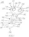
- FIG. 1is a perspective view of an implant, in accordance with an aspect of the present invention.
- FIG. 2is a top view of the implant of FIG. 1 , in accordance with an aspect of the present invention
- FIG. 3is a bottom view of the implant of FIG. 1 , in accordance with an aspect of the present invention.
- FIG. 4is a side view of the implant of FIG. 1 , in accordance with an aspect of the present invention.
- FIG. 5is a first end view of the implant of FIG. 1 , in accordance with an aspect of the present invention.
- FIG. 6is a second end view of the implant of FIG. 1 , in accordance with an aspect of the present invention.
- FIG. 7is a perspective end view of the implant of FIG. 1 , in accordance with an aspect of the present invention.
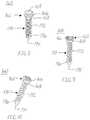
- FIG. 8is a top perspective view of a first bone fastener, in accordance with an aspect of the present invention.
- FIG. 9is a side view of the first bone fastener of FIG. 8 , in accordance with an aspect of the present invention.
- FIG. 10is a bottom perspective view of the first bone fastener of FIG. 8 , in accordance with an aspect of the present invention.
- FIG. 11is a top perspective view of a second bone fastener, in accordance with an aspect of the present invention.
- FIG. 12is a side view of the second bone fastener of FIG. 11 , in accordance with an aspect of the present invention.
- FIG. 13is a bottom perspective view of the second bone fastener of FIG. 11 , in accordance with an aspect of the present invention.
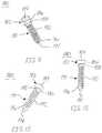
- FIG. 14is a perspective view of two bones with a bunion on one of the two bones, in accordance with an aspect of the present invention.
- FIG. 15is a perspective view of the bones of FIG. 14 after removal of the bunion, in accordance with an aspect of the present invention.
- FIG. 16is a perspective view of the bones of FIG. 15 after a Chevron osteotomy cut is performed, in accordance with an aspect of the present invention
- FIG. 17is a perspective view of the bones of FIG. 16 after surgical correction has been performed, in accordance with an aspect of the present invention.
- FIG. 18is a perspective view of the bones of FIG. 17 after insertion of the implant of FIGS. 1-7 into the intramedullary canal of the cut bone and a drill guide coupled to the implant, in accordance with an aspect of the present invention
- FIG. 19is a perspective view of the bones with the inserted implant and coupled drill guide of FIG. 18 as a drill is inserted into a bone through the drill guide and implant, in accordance with an aspect of the present invention
- FIG. 20is a perspective view of the bones, implant and coupled drill guide of FIG. 19 after drilling two openings into the bone through the implant and drill guide, in accordance with an aspect of the present invention
- FIG. 21is a perspective view of the bones and implant of FIG. 20 with two bone fasteners inserted into the bone through the implant, in accordance with an aspect of the present invention
- FIG. 22is a perspective view of the bones and implant of FIG. 21 after removing the portion of the bone overhang to expose the central opening, in accordance with an aspect of the present invention
- FIG. 23is a perspective view of the bones and implant of FIG. 22 after drilling a hole through the central opening into the bone, in accordance with an aspect of the present invention
- FIG. 24is a perspective view of the bones and implant of FIG. 23 after inserting a third bone fastener into the bone through the central opening, in accordance with an aspect of the present invention
- FIG. 25is a perspective view of the bones and implant of FIG. 24 with a transparent bone showing the insertion position of the implant and bone fasteners, in accordance with an aspect of the present invention
- FIG. 26depicts the surgical method of using the implant of FIGS. 1-7 , in accordance with an aspect of the present invention
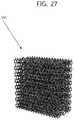
- FIG. 27is a perspective view of a porous region
- FIG. 28is a front view of a honeycomb structure of a porous region
- FIG. 29Ais a density profile across a cross-section of the porous region
- FIG. 29Bis a density profile across a cross section of the porous region from the outside of the porous region to an interior region;
- FIG. 29Cis a density profile across a cross-section of the porous region from the outside of the porous region to an interior region;
- FIG. 29Dis a density profile across a cross-section of the porous region from the outside of the porous region to an interior region;
- FIG. 30Ais a density profile across a cross-section of the porous region from the outside of the porous region to an interior region;
- FIG. 30Bis a density profile across a cross-section of the porous region from the outside of the porous region to an interior region;
- FIG. 30Cis a density profile across a cross-section of the porous region from the outside of the porous region to an interior region;
- FIG. 31Ais a side view of another embodiment
- FIG. 31Bis an end perspective view of the embodiment of FIG. 31A ;
- FIG. 31Cis a top or plan view of the embodiment of FIG. 31A ;
- FIG. 32shows a side view of a plug coupled to two portions of a bone.
- bone fixation deviceGenerally stated, disclosed herein is an embodiment of a bone fixation device.
- the terms “bone fixation device,” “bone fixation implant,” “bunion correction device,” “bunion device,” “bunion correction implant,” “bunion implant,” “device,” and “implant”may be used interchangeably as they essentially describe the same type of device. Further, a surgical methods for using the bone fixation device are discussed.
- proximal, distal, anterior, posterior, medial, lateral, superior and inferiorare defined by their standard usage for indicating a particular part of a bone or implant according to the relative disposition of the natural bone or directional terms of reference.
- proximalmeans the portion of an implant nearest the torso
- distalindicates the portion of the implant farthest from the torso.
- anterioris a direction towards the front side of the body
- posteriormeans a direction towards the back side of the body
- medialmeans towards the midline of the body
- lateralis a direction towards the sides or away from the midline of the body
- superiormeans a direction above
- inferiormeans a direction below another object or structure.
- proximalwill mean the portion of the device closest or nearest the insertion instrument.
- distalshall mean the portion of the device farthest away from the insertion instrument.
- the implant 100may have a first end 102 opposite a second end 104 , a top surface 106 opposite a bottom surface 108 , and a first side 110 opposite a second side 112 .
- the implant 100including, for example, a plate or body portion 120 and a stem, insertion, or engagement portion 140 .
- the plate portion 120being positioned at the first end 102 and the stem portion 140 extending away from the plate portion 120 to the second end 104 of the implant 100 , as shown in FIGS. 1-4 and 7 .
- the top surface 106 of the implantmay be, for example, polished to prevent soft tissue irritation
- the bottom surface 108may include a surface roughness or texture to enable bone ongrowth, assists with resisting pull-out, and acts as a rasp when implanting and cutting bone.
- the implant 100may further be curved in a medial-lateral direction to correspond to the natural shape of the patient's bone.
- the plate portion 120may include a first lobe or ear 122 on the first side 110 of the implant 100 and a second lobe or ear 124 on the second side 112 of the implant 100 .
- the first lobe 122may include a first opening or screw hole 128 .
- the first opening 128may include threads 130 for coupling to the head of a bone fastener (not shown) with corresponding threads.
- the second lobe 124may include a second opening or screw hole 132 .
- the second opening 132may include threads 134 for coupling to the head of a bone fastener (not shown) with corresponding threads.
- the plate portion 120may also include a depression or inset region 126 positioned between the first and second lobes 122 , 124 on the first end 102 of the implant 100 .
- the threads 130 , 134 of the first and second openings 128 , 132provide for a locking engagement between the plate portion 120 of the implant and any inserted locking fasteners to provide for bony fixation.
- the first and second openings 128 , 132may for some embodiments be non-threaded to allow for multi-axial placement of a bone fastener.
- the stem portion 140may include a central screw hole or opening 136 positioned adjacent to the plate portion 120 , as shown in FIGS. 1-3 and 7 .
- the opening 136may include a surface 138 which may be, for example, angled or conical to receive the head of a bone fastener.
- the angled or conical surface 138 of the opening 136allows for variable screw angulation insertion.
- the variable screw angulation insertion of opening 136may be, for example, 30° in either direction to assist with compression and stabilization of the bone segments being joined.
- the stem portion 140may also include at least one first barb 142 positioned on the first side 110 of the implant 100 and at least one second barb 144 positioned on the second side 112 of the implant 100 .
- the stem portion 140may include, for example, two first barbs 142 and two second barbs 144 , as shown in the depicted embodiment.
- the stem portion 140may also include insertion tip barbs 154 extending out from the first and second sides 110 , 112 of the insertion tip 152 .
- the stem portion 140may include, for example, at least one barb, more specifically, between approximately three and ten barbs.
- the barbs 142 , 144 , 154may be configured for a bone clearing broaching effect during insertion and to prevent pullout of the implant 100 after insertion into the patient's bone.
- the barbs 142 , 144 , 154may be, for example, angled away from the longitudinal axis of the stem portion 140 .
- the barbs 142 , 144 , 154as shown in FIGS. 1-3 , are symmetrical relative to each other, however it is contemplated that the barbs 142 , 144 , 154 on the first side 110 of the implant 100 may be offset from the barbs 142 , 144 , 154 on the second side 112 of the implant 100 .
- the stem portion 140may also include a porous region, architecture or lattice 146 along at least a portion of the stem portion 140 which may be positioned centrally.
- the porous region 146may include a plurality of openings 148 which extend through the stem portion 140 from the top surface 106 to the bottom surface 108 and a plurality of struts 148 to create the lattice structure 146 .
- the stem portion 140may be configured to be positioned within an intramedullary canal at a fusion site, such as at an osteotomy site (e.g., a fracture site), with the plate portion 120 positioned exterior to the site and in abutment with a side of a bone segment.
- the porous architecture of the stem portion 140may thereby promote osteosynthesis (e.g., bone formation and ingrowth) on either side of the stem portion 140 .
- the porous region 146 of the stem portion 140may be any architecture that provides openings or spaces at least in the engagement or exterior surfaces of the stem portion 140 that contact the bone.
- the openings or spaces of the stem portion 140extend through the stem portion 140 such that bone is able to grow and penetrate into and within the stem portion 140 .
- the stem portion 140may include a porosity, in the horizontal and/or vertical direction (e.g., along the proximal-distal and/or medial-lateral and/or plantar-dorsal directions) within the range of about 60% to about 90%, or within the range of about 65% to about 85%, or within the range of about 70% to about 80%.
- the porous region 146 of the stem portion 140may be a defined or uniform architecture or pattern, may be a randomly generated or distributed architecture or lattice, or may include a different architecture in differing portions of the stem portion 140 .
- the stem portion 140may include a portion which includes the porous region 146 .
- the stem portion 140may include a substantially uniform pattern of unit cells (e.g., substantially cubic or quadrilateral lattice structure).
- the porous region 146 of the stem portion 140may be formed of a structure of about 1 mm unit cells.
- the porous region 146 of the stem portion 140may be formed of interconnected elongate strut members 150 .
- the porous region 146 of the stem portion 140may be formed, for example, of diamond cut interconnected elongate strut members 150 with a diameter within the range of about 0.1 mm to about 0.5 mm, or within the range of about 0.2 mm to about 0.4 mm, or about 0.3 mm.
- the porous region 146 of the stem portion 140may be formed via diamond cutting (or a similar process) the structure and/or diamond cutting (or a similar process) struts or other members that are utilized to form the architecture.
- the stem portion 140may further include an insertion end or tip 152 , as shown in FIGS. 1-3 and 7 .
- the insertion tip 152may extend from the stem portion 140 to a generally pointed end at the second end 104 of the implant 100 .
- the insertion tip 152may include insertion tip barbs 154 extending out from the first and second sides 110 , 112 of the insertion tip 152 .
- the insertion tip barbs 152may assist with bone clearing during insertion and securing the implant 100 in the patient's bone.
- the entire insertion tip 152may be, for example, polished and tapered to provide for an easier insertion into the patient's bone segment, as best seen in FIGS. 4 and 7 .
- the implant 100may have, for example, a length of 30 mm and a thickness of 2 mm with barbs 142 , 144 at approximately a 45° angle and having a length of approximately 5 mm.
- the implant 100may further include, for example, a porous region 146 with diamond cut interconnected elongate strut members 150 with a diameter of 0.3 mm and a 1 mm unit cell with a porosity of approximately 70-79%.
- the implant 100may be, for example, made of a medical grade titanium.
- the implant 100may also be formed, for example, using additive manufacturing methods.
- the implant 100may also include, for example, a stem portion 140 with a surface roughness and geometry for osteosynthesis in an intramedullary canal.
- the first fastener 160may include a head portion 162 coupled to a shaft portion 170 by a neck 168 .
- the head portion 162 of the first fastener 160may include an opening 164 for receiving a driver or drill to rotate the first fastener 160 for insertion or removal from a patient's bone.
- the opening 164may have, for example, a polygonal shape, such as, a hexagonal shape.
- the head portion 162 of the first fastener 160may also include threads 166 on the exterior surface of the head portion 162 . In alternative embodiments, the head portion 162 may not include threads 166 and rather may have a smooth exterior surface.
- the neck 168may be a relatively smooth region positioned between the threads 166 of the head portion 162 and the threads 172 of the shaft portion 170 .
- the shaft portion 170may include threads 172 extending along the length of the shaft portion 170 to a tip 174 of the first fastener 160 .
- the tip 174may include at least one cutting edge 176 to assist with insertion into a patient's bone.
- the second fastener 180may include a head portion 182 coupled to a shaft portion 190 by a neck 188 .
- the head portion 182 of the second fastener 180may include an opening 184 for receiving a driver or drill to rotate the second fastener 180 for insertion or removal from a patient's bone.
- the opening 184may have, for example a polygonal shape, such as, a hexagonal shape.
- the head portion 182 of the second fastener 180may also include a tapered or curved exterior surface 186 extending from a top surface of the second fastener 180 to the neck 188 of the second fastener 180 .
- the exterior surface 186may have a shape, for example, that is curved to mate with the conical surface 138 of the central opening 136 .
- the neck 188may be a relatively smooth region positioned between the exterior surface 186 of the head portion 182 and the threads 192 of the shaft portion 190 .
- the shaft portion 190 of themay include threads 192 extending along the length of the shaft portion 190 to a tip 194 of the second fastener 180 .
- the tip 194may include at least one cutting edge 196 to assist with insertion into a patient's bone.
- a method of insertion of the implant 100may include, for example, making an incision and preparing a patient's bones 250 .
- the methodmay also include removing a protrusion from the first bone 252 and making a cut on the first bone 254 .
- the methodmay include performing a correction on the first bone for alignment 256 and inserting an implant into the first intramedullary canal 258 .
- the methodmay further include attaching a drill guide to the openings in the plate portion of the implant 260 and drilling two holes in the bone through the plate openings 262 .
- the methodmay also include inserting bone fasteners into the two holes 264 and removing the bone overhang to expose the plate center opening 266 .
- the methodmay still further include drilling a third hole in the bone through the plate center opening 268 and inserting a bone fastener into the plate center opening 270 .
- the methodmay include completing the surgical procedure and closing the incision in the patient 272 .
- first bone 200 with a medial protrusion or bump 204 and a second bone 202are shown.
- first bone 200may be, for example, a first metatarsal
- medial protrusion 204may be, for example, a bunion
- the second bone 202may be, for example, a proximal phalanges.
- the bunion 204may then be removed, as shown in FIG. 15 .
- an osteotomymay be performed, for example, a Chevron osteotomy, to perform a cut 206 in the first bone 200 , as illustrated in FIG. 16 .
- the cut 206may form a first segment 208 and a second segment 210 of the first bone 200 .
- the first and second segments 208 , 210may then be re-aligned to surgically correct the bone deformity.
- the stem portion 140 of the implant 100may be inserted into the intramedullary canal of the second segment 210 of the first bone 200 , as illustrated in FIG. 18 .
- an engagement end 214 of a drill guide 212may be coupled to the openings 128 , 132 of the implant 100 .
- the drill guide 212may include at least one drill opening 216 for receiving a drill 218 for drilling holes into the first segment 208 of the first bone 200 through the openings 128 , 132 in the implant 100 , as shown in FIGS. 19 and 20 .
- bone fasteners 160may be inserted through the openings 128 , 132 in the implant 100 and into the second segment 208 of the first bone 200 .
- the head portions 162 of the first fasteners 160having threads 166 which correspond to the threads 130 , 134 in the openings 128 , 132 of the plate portion 120 of the implant 100 to secure the first fasteners 160 to the implant 100 .
- the overhanging portion of the second segment 210 of the first bone 200may be removed to expose the central opening 136 , as shown in FIG. 22 .
- a drill 218may be used to drill an opening into the second segment 210 of the first bone 200 , as shown in FIG. 23 .
- a drill guidemay be used to drill the hole in the bone segment 210 through the central opening 136 .
- a bone fastener 180may be inserted through the central opening 136 of the implant 100 and into the second segment 210 of the first bone 200 .
- the tapered or curved exterior surface 186 of the second fastener 180mates with the angled or curved edge 138 of the central opening 136 to enable the second fastener 180 to be inserted at various angles to allow for the desired compression and stabilization. Finally, the procedure may be completed and the patient's incision closed.
- FIG. 27is a perspective view of a porous region 340 that can be used in the porous region 146 .
- This porous region 146 or 340can have a standard lattice structure that can be either variable in porosity across a cross-sectional profile or have a standard porosity profile.
- Each of the cells or units of the porous region 146 or 340can have any suitable or desirable shape which can include but is not limited to a pentagon, a hexagon, a square, a quadrangle and a honeycomb pattern.
- An example of this patternis shown in FIG. 28 which shows a honeycomb pattern 370 , which is a pattern for each cell of a porous region or any suitable cell of a porous region.
- the honeycomb patternhas a width or opening such as width or opening 372 .
- width or opening 372As the porosity and thereby the density of the structure changes, the width or size of this opening 372 can change as well. For example, in a less porous structure, or more dense structure, the distance across 372 could be less. However, in a less dense structure or more porous structure, the distance across 372 could be more.
- the porosity or density of the porous region 146 , 340 such as that of each cellcan vary across a cross-sectional profile.
- FIG. 29Ashows a steadily increasing density of the structure from an outside region towards an inner region of the porous structure 146 and 340 .
- FIG. 29Bshows an alternative porosity profile which shows an ever increasing density from an outside region towards an inner region of the porous region 146 .
- FIG. 29Cshows a stepwise increase in density across a cross-sectional profile from outside towards inside, while FIG. 29D shows an increasing and then decreasing density of the porous region 146 , 340 .
- FIG. 30Ashows a steadily decreasing density from an outer region of the porous region 146 , 340 .
- FIG. 30Bshows an increasing or accelerating decrease in density across the cross section of the porous region 146 , 340 .
- FIG. 30Cshows a step wise decrease in density from an outer region towards an inner region of the porous region 146 and 340 . While these porosity profiles can be variable on one side they can also be variable from both sides of the porous regions 146 , 340 , therefore from both sides of the porous region, the porosity and thereby the density can be variable.
- FIG. 31Ais a side view of another embodiment
- FIG. 31Bis an end perspective view of the embodiment of FIG. 31A
- FIG. 31Cis a top or plan view of the embodiment of FIG. 31A
- the plug 270comprises a plate section 271 , a joining section 272 , which is coupled to the plate section at a first end and coupled to a stopper 278 at a second end.
- Plate section 271 and joining section 272combine to form a substantially L-shaped plate.
- Plate section 271includes screw holes for receiving orthopedic screws to fix plate section 270 to an adjacent bone.
- plug body 277is configured to be shaped in a bulbous manner having an elongated body that has an increasingly narrower section which ends at a rounded end 277 a .
- Plug 270is configured to be inserted into an open end of a bone such as a cleanly fractured bone. Plate 271 is then configured to be clamped or screwed into an adjacent bone.
- FIG. 31Ashows two axis lines 270 i and 270 j .
- Axis line 270 iis the longitudinal axis for a center region of the plug body 277
- axis line 271 iis the longitudinal axis for the plate and corresponds to a bottom surface of the plate.
- Arrow 270 jdenotes the distance d from the axis line 270 i to the axis line 271 i .
- This distance dcan be varied depending on the need in the form of an offset based upon bone structure. For example, in at least one embodiment, this distance d could vary from any number from 1-20 mm. Alternatively, the distance d is bridged by the length of joining section 272 as well as a portion of the radius of stopper 278 .
- FIG. 32shows an open side view of a plug inserted into a bone and configured to fuse to adjacent broken bones together.
- Plug body 277 as well as the lattice mesh structure or cage 275is configured in at least one embodiment to fit inside a canal of a bone.
- These two bonescan be fused together via the insertion of plug 270 wherein plug body 277 which is a solid bulbous body inserts into an end of bone 282 and plate 271 is clamped to a top or side portion of bone 281 via fasteners such as fastener 283 .
- the fastenersare configured to fit through holes 271 a , 271 b , and 271 c .
- the cage or mesh section 275is configured to intermesh with bone 282 such that it forms multiple interfaces to promote bone growth.
- the mesh or cage sectioncan have a variable lattice structure of different shapes or porosity such as that disclosed in FIGS. 27-30C .
- the lattice mesh structurecan have a greater porosity on the outer regions of the cage and less porosity as the cage approaches body 277 such as between line 275 a and plug 270 .
- the lattice mesh structure 275can have a lower porosity (thereby greater density) on the outer regions of the cage and a higher porosity and less density as the lattice or mesh structure approaches the body 277 .
- the lattice mesh structurecan be of lower density between line 275 a and the solid plug 270 , vs. the lattice mesh structure between line 275 a and the outer region of the lattice mesh.
- the latticecan have multiple different shapes such as a diamond shape or a honeycomb shape as well.
- a method or device that “comprises,” “has,” “includes,” or “contains” one or more steps or elementspossesses those one or more steps or elements, but is not limited to possessing only those one or more steps or elements.
- a step of a method or an element of a device that “comprises,” “has,” “includes,” or “contains” one or more featurespossesses those one or more features, but is not limited to possessing only those one or more features.
- a device or structure that is configured in a certain wayis configured in at least that way, but may also be configured in ways that are not listed.
Landscapes
- Health & Medical Sciences (AREA)
- Orthopedic Medicine & Surgery (AREA)
- Surgery (AREA)
- Life Sciences & Earth Sciences (AREA)
- Heart & Thoracic Surgery (AREA)
- Nuclear Medicine, Radiotherapy & Molecular Imaging (AREA)
- Engineering & Computer Science (AREA)
- Biomedical Technology (AREA)
- Neurology (AREA)
- Medical Informatics (AREA)
- Molecular Biology (AREA)
- Animal Behavior & Ethology (AREA)
- General Health & Medical Sciences (AREA)
- Public Health (AREA)
- Veterinary Medicine (AREA)
- Prostheses (AREA)
- Surgical Instruments (AREA)
Abstract
Description
Claims (13)
Priority Applications (3)
| Application Number | Priority Date | Filing Date | Title |
|---|---|---|---|
| US15/665,097US11058468B2 (en) | 2016-07-29 | 2017-07-31 | Bone fixation device and method of use |
| US17/313,269US11937860B2 (en) | 2016-07-29 | 2021-05-06 | Bone fixation device and method of use |
| US18/585,909US20240341824A1 (en) | 2016-07-29 | 2024-02-23 | Bone fixation device and method of use |
Applications Claiming Priority (2)
| Application Number | Priority Date | Filing Date | Title |
|---|---|---|---|
| US201662368370P | 2016-07-29 | 2016-07-29 | |
| US15/665,097US11058468B2 (en) | 2016-07-29 | 2017-07-31 | Bone fixation device and method of use |
Related Child Applications (1)
| Application Number | Title | Priority Date | Filing Date |
|---|---|---|---|
| US17/313,269ContinuationUS11937860B2 (en) | 2016-07-29 | 2021-05-06 | Bone fixation device and method of use |
Publications (2)
| Publication Number | Publication Date |
|---|---|
| US20180028242A1 US20180028242A1 (en) | 2018-02-01 |
| US11058468B2true US11058468B2 (en) | 2021-07-13 |
Family
ID=61012127
Family Applications (3)
| Application Number | Title | Priority Date | Filing Date |
|---|---|---|---|
| US15/665,097Active2037-10-27US11058468B2 (en) | 2016-07-29 | 2017-07-31 | Bone fixation device and method of use |
| US17/313,269Active2038-03-22US11937860B2 (en) | 2016-07-29 | 2021-05-06 | Bone fixation device and method of use |
| US18/585,909PendingUS20240341824A1 (en) | 2016-07-29 | 2024-02-23 | Bone fixation device and method of use |
Family Applications After (2)
| Application Number | Title | Priority Date | Filing Date |
|---|---|---|---|
| US17/313,269Active2038-03-22US11937860B2 (en) | 2016-07-29 | 2021-05-06 | Bone fixation device and method of use |
| US18/585,909PendingUS20240341824A1 (en) | 2016-07-29 | 2024-02-23 | Bone fixation device and method of use |
Country Status (2)
| Country | Link |
|---|---|
| US (3) | US11058468B2 (en) |
| WO (1) | WO2018023131A1 (en) |
Families Citing this family (19)
| Publication number | Priority date | Publication date | Assignee | Title |
|---|---|---|---|---|
| AU2016267051A1 (en) | 2015-05-22 | 2017-12-14 | Stryker European Operations Limited | Joint or segmental bone implant for deformity correction |
| US10517655B2 (en)* | 2015-06-08 | 2019-12-31 | Andrew Lundquist | Combined intramedullary-extramedullary bone stabilization and alignment system |
| US11058468B2 (en) | 2016-07-29 | 2021-07-13 | Additive Orthopaedics, LLC | Bone fixation device and method of use |
| KR102162502B1 (en) | 2017-05-22 | 2020-10-06 | 주식회사 엘지화학 | Polymer for liquid crystal aligning agent, amd liquid crystal aligning agent comprising the same, and liquid crystal aligning film, liquid crystal display device using the same |
| KR102020030B1 (en) | 2017-08-24 | 2019-09-10 | 주식회사 엘지화학 | Polymer for liquid crystal aligning agent, amd liquid crystal aligning agent composition comprising the same, and liquid crystal aligning film, liquid crystal display device using the same |
| US11147679B2 (en) | 2018-02-05 | 2021-10-19 | Paragon Advanced Technologies, Inc. | Bone fixation device |
| US11224470B2 (en) | 2018-05-09 | 2022-01-18 | Warsaw Orthopedic, Inc. | Bone screw and method of manufacture |
| US11191582B2 (en) | 2018-05-09 | 2021-12-07 | Warsaw Orthopedic, Inc. | Bone screw and method of manufacture |
| US10575886B2 (en) | 2018-05-09 | 2020-03-03 | Warsaw Orthopedic, Inc. | Bone screw and method of manufacture |
| US10993753B2 (en) | 2018-05-09 | 2021-05-04 | Warsaw Orthopedic, Inc. | Bone screw and method of manufacture |
| US10646263B2 (en)* | 2018-07-11 | 2020-05-12 | Crossroads Extremity Systems, Llc | Bunion correction system and method |
| US11660201B2 (en)* | 2018-10-25 | 2023-05-30 | Wright Medical Technology, Inc. | Systems, apparatuses, and methods for correcting a bone defect |
| US11331123B2 (en) | 2018-11-28 | 2022-05-17 | Warsaw Orthopedic, Inc. | Spinal implant |
| WO2020107072A1 (en)* | 2018-11-28 | 2020-06-04 | The Sydney Children's Hospitals Network (Randwick And Westmead) | Guided growth device and method |
| US11426223B2 (en) | 2019-02-22 | 2022-08-30 | Warsaw Orthopedic, Inc. | Bone screw and method of manufacture |
| WO2021026357A1 (en)* | 2019-08-07 | 2021-02-11 | Crossroads Extremity Systems, Llc | Bunion correction system and method |
| FR3099875A1 (en)* | 2019-08-12 | 2021-02-19 | Novastep | Intramedullary implant for transverse osteotomy |
| CA3210916A1 (en)* | 2021-02-10 | 2022-08-18 | Crossroads Extremity Systems, Llc | Bunion correction system and method |
| US12408957B2 (en)* | 2021-09-21 | 2025-09-09 | Pace Surgical, Inc. | Orthopaedic implant system for compression-distraction of joints |
Citations (87)
| Publication number | Priority date | Publication date | Assignee | Title |
|---|---|---|---|---|
| US5211664A (en) | 1992-01-14 | 1993-05-18 | Forschungsinstitut, Davos Laboratorium Fur Experimentelle Chirugie | Shell structure for bone replacement |
| US5360448A (en) | 1991-10-07 | 1994-11-01 | Thramann Jeffrey J | Porous-coated bone screw for securing prosthesis |
| US5650108A (en) | 1994-10-06 | 1997-07-22 | Merck Patent Gesellschaft Mit Beschrankter Haftung | Porous bone replacement materials |
| US5856367A (en) | 1994-02-18 | 1999-01-05 | Minnesota Mining And Manufacturing Company | Biocompatible porous matrix of bioabsorbable material |
| US5869080A (en) | 1995-05-30 | 1999-02-09 | Johnson & Johnson Medical, Inc. | Absorbable implant materials having controlled porosity |
| US5876452A (en) | 1992-02-14 | 1999-03-02 | Board Of Regents, University Of Texas System | Biodegradable implant |
| US6149688A (en) | 1995-06-07 | 2000-11-21 | Surgical Dynamics, Inc. | Artificial bone graft implant |
| US6206924B1 (en) | 1999-10-20 | 2001-03-27 | Interpore Cross Internat | Three-dimensional geometric bio-compatible porous engineered structure for use as a bone mass replacement or fusion augmentation device |
| US6228111B1 (en) | 1995-09-27 | 2001-05-08 | Bionx Implants Oy | Biodegradable implant manufactured of polymer-based material and a method for manufacturing the same |
| US6235225B1 (en) | 1999-08-10 | 2001-05-22 | Ngk Spark Plug Co., Ltd. | Process for producing biocompatible implant material |
| US6432107B1 (en) | 2000-01-15 | 2002-08-13 | Bret A. Ferree | Enhanced surface area spinal fusion devices |
| US6436426B1 (en) | 2000-08-18 | 2002-08-20 | Industrial Technology Research Institute | Process for producing porous polymer materials |
| US20030009225A1 (en) | 2001-05-01 | 2003-01-09 | Khandkar Ashok C. | Radiolucent bone graft |
| FR2827157A1 (en) | 2001-07-10 | 2003-01-17 | Vitatech | Intersomatic implant for stabilizing cervical vertebrae has main upper and lower faces with convex curvature in two directions |
| US6511511B1 (en) | 1997-05-30 | 2003-01-28 | Osteobiologics, Inc. | Fiber-reinforced, porous, biodegradable implant device |
| US6527810B2 (en) | 1997-10-01 | 2003-03-04 | Wright Medical Technology, Inc. | Bone substitutes |
| US6530956B1 (en) | 1998-09-10 | 2003-03-11 | Kevin A. Mansmann | Resorbable scaffolds to promote cartilage regeneration |
| US6626945B2 (en) | 2000-03-14 | 2003-09-30 | Chondrosite, Llc | Cartilage repair plug |
| US20030199875A1 (en) | 2002-04-23 | 2003-10-23 | Citieffe S.R.L. | Stabilizing support for opening- and closing-wedge osteotomies |
| US20040082999A1 (en) | 2001-01-30 | 2004-04-29 | Robert Mathys | Bone implant, in particular, an inter-vertebral implant |
| US20040243237A1 (en) | 2001-08-11 | 2004-12-02 | Paul Unwin | Surgical implant |
| US20040258732A1 (en) | 2001-11-27 | 2004-12-23 | Yasuo Shikinami | Implant material and process for producing the same |
| US6840960B2 (en) | 2002-09-27 | 2005-01-11 | Stephen K. Bubb | Porous implant system and treatment method |
| US20050187555A1 (en) | 2004-02-24 | 2005-08-25 | Biedermann Motech Gmbh | Bone anchoring element |
| US20060111715A1 (en) | 2004-02-27 | 2006-05-25 | Jackson Roger P | Dynamic stabilization assemblies, tool set and method |
| US20060241763A1 (en) | 1998-08-03 | 2006-10-26 | Synthes (Usa) | Multipiece bone implant |
| US20060276788A1 (en) | 2005-05-26 | 2006-12-07 | Amedica Corporation | Osteoconductive spinal fixation system |
| US7235079B2 (en) | 2004-11-18 | 2007-06-26 | Acumed Llc | Composite bone fasteners |
| US20070156240A1 (en) | 2005-12-29 | 2007-07-05 | Industrial Technology Research Institute | Spinal fusion device |
| US20070161985A1 (en) | 2005-12-05 | 2007-07-12 | Kentomia, Llc . | Screws configured to engage bones, and methods of attaching implants to skeletal regions |
| US20070203584A1 (en) | 2006-02-14 | 2007-08-30 | Amit Bandyopadhyay | Bone replacement materials |
| US7351280B2 (en) | 2004-02-10 | 2008-04-01 | New York University | Macroporous, resorbable and injectible calcium phosphate-based cements (MCPC) for bone repair, augmentation, regeneration, and osteoporosis treatment |
| US20080269893A1 (en) | 2007-04-25 | 2008-10-30 | Jmea Corporation | Prosthesis with a Selectively Applied Bone Growth Promoting Agent |
| US20090187249A1 (en) | 2008-01-23 | 2009-07-23 | Osman Said G | Biologic Vertebral Reconstruction |
| US7578851B2 (en) | 2005-12-23 | 2009-08-25 | Howmedica Osteonics Corp. | Gradient porous implant |
| US20090240324A1 (en) | 2008-03-19 | 2009-09-24 | Boston Scientific Scimed, Inc. | Drug Eluting Stent and Method of Making the Same |
| US20100042214A1 (en)* | 2008-08-13 | 2010-02-18 | Nebosky Paul S | Drug delivery implants |
| US20100094420A1 (en) | 2004-07-02 | 2010-04-15 | Grohowski Jr Joseph A | Porous Bone Fixation Device |
| US20100249851A1 (en) | 2005-01-28 | 2010-09-30 | Orthohelix Surgical Designs, Inc. | Orthopedic plate for use in small bone repair |
| US20100262245A1 (en) | 2009-02-18 | 2010-10-14 | Alfaro Arthur A | Intervertebral spacer |
| US20110004307A1 (en) | 2006-10-16 | 2011-01-06 | Ahn Edward S | Fusion device, systems and methods thereof |
| US7879109B2 (en) | 2004-12-08 | 2011-02-01 | Biomet Manufacturing Corp. | Continuous phase composite for musculoskeletal repair |
| US7892265B2 (en) | 2006-12-28 | 2011-02-22 | Mi4Spine, Llc | Surgical screw including a body that facilitates bone in-growth |
| US7910690B2 (en) | 2003-06-20 | 2011-03-22 | Kensey Nash Bvf Technology, Llc | High density fibrous polymers suitable for implant |
| US20110071635A1 (en) | 2009-09-23 | 2011-03-24 | Zimmer Spine, Inc. | Composite implant |
| US7943677B2 (en) | 2005-10-21 | 2011-05-17 | University Of South Florida | Method of producing interconnected volumetric porosity in materials |
| US20110172775A1 (en) | 2010-01-07 | 2011-07-14 | Eric Flickinger | Interbody implant with graft retaining bone cap |
| US20110218626A1 (en)* | 2010-03-08 | 2011-09-08 | Krinke Todd A | Apparatus and methods for securing a bone implant |
| US20110301709A1 (en) | 2010-06-03 | 2011-12-08 | Kilian Kraus | Intervertebral implant |
| US20120089197A1 (en) | 2010-10-10 | 2012-04-12 | Anderson Gregory S | Arthrodesis implant apparatus and method |
| WO2012109748A1 (en) | 2011-02-14 | 2012-08-23 | The Royal Institution For The Advancement Of Learning / Mcgill University | Systems and methods for injecting fluid into bone and for inserting bone screws, and bone screws for same |
| US8292967B2 (en) | 2005-04-21 | 2012-10-23 | Biomet Manufacturing Corp. | Method and apparatus for use of porous implants |
| US20120271361A1 (en) | 2009-10-02 | 2012-10-25 | Drexel University | Functionalized Nanodiamond Reinforced Biopolymers |
| US20120271362A1 (en) | 2009-10-13 | 2012-10-25 | The Royal Institution for the Advancement of Learn McGill University | Porous bone screw |
| US8337873B2 (en) | 2004-10-22 | 2012-12-25 | The Board Of Trustees Of The University Of Illinois | Hollow and porous orthopaedic or dental implant that delivers a biological agent |
| US20120330420A1 (en) | 2001-05-01 | 2012-12-27 | Amedica Corporation | Spinal fusion implants |
| US20130022943A1 (en) | 2008-07-02 | 2013-01-24 | Zimmer Dental, Inc. | Porous implant with non-porous threads |
| US8383024B2 (en) | 2005-11-04 | 2013-02-26 | Ppd Meditech | Porous material and method for fabricating same |
| US8389588B2 (en) | 2003-12-04 | 2013-03-05 | Kensey Nash Corporation | Bi-phasic compressed porous reinforcement materials suitable for implant |
| US20130066435A1 (en) | 2010-03-09 | 2013-03-14 | Synchro Medical | Arthrodesis implant |
| US20130090733A1 (en) | 2011-10-10 | 2013-04-11 | Markus Kraft | Implant with compliant layer |
| US20130116793A1 (en) | 2010-07-23 | 2013-05-09 | Privelop-Spine Ag | Surgical implant |
| US8445554B2 (en) | 2004-04-29 | 2013-05-21 | Kensey Nash Corporation | Compressed porous materials suitable for implant |
| US20130150965A1 (en) | 2011-12-12 | 2013-06-13 | Alan G. Taylor | Fusion implant |
| US8475505B2 (en) | 2008-08-13 | 2013-07-02 | Smed-Ta/Td, Llc | Orthopaedic screws |
| US20130178900A1 (en) | 2008-12-05 | 2013-07-11 | Imds Corporation | Porous Implants |
| US8500843B2 (en) | 2004-07-02 | 2013-08-06 | Praxis Powder Technology, Inc. | Controlled porosity article |
| US20130211533A1 (en) | 2012-02-09 | 2013-08-15 | Mx Orthopedics, Corp. | Porous coating for orthopedic implant utilizing porous, shape memory materials |
| US8529625B2 (en) | 2003-08-22 | 2013-09-10 | Smith & Nephew, Inc. | Tissue repair and replacement |
| US8535357B2 (en) | 2004-12-09 | 2013-09-17 | Biomet Sports Medicine, Llc | Continuous phase compositions for ACL repair |
| US8657827B2 (en) | 2001-05-25 | 2014-02-25 | Conformis, Inc. | Surgical tools for arthroplasty |
| US8700198B2 (en) | 2010-06-08 | 2014-04-15 | Smith & Nephew, Inc. | Implant components and methods |
| US20140107785A1 (en) | 2012-10-11 | 2014-04-17 | Rhausler, Inc. | Bone plate and fusion cage interface |
| US8715366B2 (en) | 2005-10-25 | 2014-05-06 | Globus Medical, Inc. | Porous and nonporous materials for tissue grafting and repair |
| WO2014068259A1 (en) | 2012-11-05 | 2014-05-08 | De Lavigne Sainte Suzanne Christophe | Intraosseous screw for fixing a bone fragment or a transplant to a bone and method for producing such an intraosseous screw |
| US20140188237A1 (en) | 2012-12-27 | 2014-07-03 | Wright Medical Technology, Inc. | Device and method for fixation for bone or soft tissue deformity of digits |
| US20140277554A1 (en) | 2013-03-13 | 2014-09-18 | Arrowhead Medical Device Technologies Llc | Hammertoe Implant with Enhanced Gripping Surfaces |
| US20150032220A1 (en) | 2012-10-19 | 2015-01-29 | Tyber Medical Llc | Wedge Osteotomy Device and Method Of Use |
| US20150045903A1 (en) | 2013-08-09 | 2015-02-12 | David J. Neal | Orthopedic implants and methods of manufacturing orthopedic implants |
| US20150088201A1 (en) | 2011-02-23 | 2015-03-26 | Farzad Massoudi | Spinal implant device with fusion cage and fixation plates and method of implanting |
| US20150100126A1 (en) | 2013-10-07 | 2015-04-09 | Warsaw Orthopedic, Inc. | Spinal implant system and method |
| US20150100129A1 (en) | 2013-10-07 | 2015-04-09 | Warsaw Orthopedic, Inc. | Spinal implant system and method |
| US20150142066A1 (en) | 2013-11-19 | 2015-05-21 | Wright Medical Technology, Inc. | Two-wire technique for installing hammertoe implant |
| US20150150607A1 (en) | 2012-05-22 | 2015-06-04 | Lifenet Health | Cortical Bone Pin |
| WO2016027025A2 (en) | 2014-08-18 | 2016-02-25 | In2Bones | Arthrodesis implant and instrument for gripping such an implant |
| US20160089138A1 (en) | 2014-09-29 | 2016-03-31 | Biomet C.V. | Method and apparatus for bone fixation |
| WO2016177790A1 (en) | 2015-05-06 | 2016-11-10 | Syntellix Ag | Arthrodesis implant |
Family Cites Families (4)
| Publication number | Priority date | Publication date | Assignee | Title |
|---|---|---|---|---|
| US9949744B2 (en)* | 2012-08-30 | 2018-04-24 | Wright Medical Technology, Inc. | Implant suitable for calcaneal osteotomy |
| US10058431B2 (en)* | 2012-10-19 | 2018-08-28 | Tyber Medical, LLC | Small joint fixation |
| US10245087B2 (en)* | 2013-03-15 | 2019-04-02 | Jcbd, Llc | Systems and methods for fusing a sacroiliac joint and anchoring an orthopedic appliance |
| US11058468B2 (en) | 2016-07-29 | 2021-07-13 | Additive Orthopaedics, LLC | Bone fixation device and method of use |
- 2017
- 2017-07-31USUS15/665,097patent/US11058468B2/enactiveActive
- 2017-07-31WOPCT/US2017/044740patent/WO2018023131A1/ennot_activeCeased
- 2021
- 2021-05-06USUS17/313,269patent/US11937860B2/enactiveActive
- 2024
- 2024-02-23USUS18/585,909patent/US20240341824A1/enactivePending
Patent Citations (93)
| Publication number | Priority date | Publication date | Assignee | Title |
|---|---|---|---|---|
| US5360448A (en) | 1991-10-07 | 1994-11-01 | Thramann Jeffrey J | Porous-coated bone screw for securing prosthesis |
| US5211664A (en) | 1992-01-14 | 1993-05-18 | Forschungsinstitut, Davos Laboratorium Fur Experimentelle Chirugie | Shell structure for bone replacement |
| US5876452A (en) | 1992-02-14 | 1999-03-02 | Board Of Regents, University Of Texas System | Biodegradable implant |
| US5856367A (en) | 1994-02-18 | 1999-01-05 | Minnesota Mining And Manufacturing Company | Biocompatible porous matrix of bioabsorbable material |
| US5650108A (en) | 1994-10-06 | 1997-07-22 | Merck Patent Gesellschaft Mit Beschrankter Haftung | Porous bone replacement materials |
| US5869080A (en) | 1995-05-30 | 1999-02-09 | Johnson & Johnson Medical, Inc. | Absorbable implant materials having controlled porosity |
| US6149688A (en) | 1995-06-07 | 2000-11-21 | Surgical Dynamics, Inc. | Artificial bone graft implant |
| US6228111B1 (en) | 1995-09-27 | 2001-05-08 | Bionx Implants Oy | Biodegradable implant manufactured of polymer-based material and a method for manufacturing the same |
| US6511511B1 (en) | 1997-05-30 | 2003-01-28 | Osteobiologics, Inc. | Fiber-reinforced, porous, biodegradable implant device |
| US6527810B2 (en) | 1997-10-01 | 2003-03-04 | Wright Medical Technology, Inc. | Bone substitutes |
| US20060241763A1 (en) | 1998-08-03 | 2006-10-26 | Synthes (Usa) | Multipiece bone implant |
| US6530956B1 (en) | 1998-09-10 | 2003-03-11 | Kevin A. Mansmann | Resorbable scaffolds to promote cartilage regeneration |
| US6235225B1 (en) | 1999-08-10 | 2001-05-22 | Ngk Spark Plug Co., Ltd. | Process for producing biocompatible implant material |
| US6206924B1 (en) | 1999-10-20 | 2001-03-27 | Interpore Cross Internat | Three-dimensional geometric bio-compatible porous engineered structure for use as a bone mass replacement or fusion augmentation device |
| US6432107B1 (en) | 2000-01-15 | 2002-08-13 | Bret A. Ferree | Enhanced surface area spinal fusion devices |
| US6626945B2 (en) | 2000-03-14 | 2003-09-30 | Chondrosite, Llc | Cartilage repair plug |
| US6436426B1 (en) | 2000-08-18 | 2002-08-20 | Industrial Technology Research Institute | Process for producing porous polymer materials |
| US20040082999A1 (en) | 2001-01-30 | 2004-04-29 | Robert Mathys | Bone implant, in particular, an inter-vertebral implant |
| US20030009225A1 (en) | 2001-05-01 | 2003-01-09 | Khandkar Ashok C. | Radiolucent bone graft |
| US20120330420A1 (en) | 2001-05-01 | 2012-12-27 | Amedica Corporation | Spinal fusion implants |
| US8657827B2 (en) | 2001-05-25 | 2014-02-25 | Conformis, Inc. | Surgical tools for arthroplasty |
| FR2827157A1 (en) | 2001-07-10 | 2003-01-17 | Vitatech | Intersomatic implant for stabilizing cervical vertebrae has main upper and lower faces with convex curvature in two directions |
| US7241313B2 (en) | 2001-08-11 | 2007-07-10 | Stanmore Implants Worldwide Limited | Surgical implant |
| US20040243237A1 (en) | 2001-08-11 | 2004-12-02 | Paul Unwin | Surgical implant |
| US20040258732A1 (en) | 2001-11-27 | 2004-12-23 | Yasuo Shikinami | Implant material and process for producing the same |
| US8119152B2 (en) | 2001-11-27 | 2012-02-21 | Takiron Co., Ltd. | Implant material and process for producing the same |
| US20030199875A1 (en) | 2002-04-23 | 2003-10-23 | Citieffe S.R.L. | Stabilizing support for opening- and closing-wedge osteotomies |
| US6840960B2 (en) | 2002-09-27 | 2005-01-11 | Stephen K. Bubb | Porous implant system and treatment method |
| US7910690B2 (en) | 2003-06-20 | 2011-03-22 | Kensey Nash Bvf Technology, Llc | High density fibrous polymers suitable for implant |
| US8529625B2 (en) | 2003-08-22 | 2013-09-10 | Smith & Nephew, Inc. | Tissue repair and replacement |
| US8389588B2 (en) | 2003-12-04 | 2013-03-05 | Kensey Nash Corporation | Bi-phasic compressed porous reinforcement materials suitable for implant |
| US7351280B2 (en) | 2004-02-10 | 2008-04-01 | New York University | Macroporous, resorbable and injectible calcium phosphate-based cements (MCPC) for bone repair, augmentation, regeneration, and osteoporosis treatment |
| US20050187555A1 (en) | 2004-02-24 | 2005-08-25 | Biedermann Motech Gmbh | Bone anchoring element |
| US20060111715A1 (en) | 2004-02-27 | 2006-05-25 | Jackson Roger P | Dynamic stabilization assemblies, tool set and method |
| US8445554B2 (en) | 2004-04-29 | 2013-05-21 | Kensey Nash Corporation | Compressed porous materials suitable for implant |
| US8500843B2 (en) | 2004-07-02 | 2013-08-06 | Praxis Powder Technology, Inc. | Controlled porosity article |
| US20100094420A1 (en) | 2004-07-02 | 2010-04-15 | Grohowski Jr Joseph A | Porous Bone Fixation Device |
| US8337873B2 (en) | 2004-10-22 | 2012-12-25 | The Board Of Trustees Of The University Of Illinois | Hollow and porous orthopaedic or dental implant that delivers a biological agent |
| US7235079B2 (en) | 2004-11-18 | 2007-06-26 | Acumed Llc | Composite bone fasteners |
| US7879109B2 (en) | 2004-12-08 | 2011-02-01 | Biomet Manufacturing Corp. | Continuous phase composite for musculoskeletal repair |
| US8535357B2 (en) | 2004-12-09 | 2013-09-17 | Biomet Sports Medicine, Llc | Continuous phase compositions for ACL repair |
| US20100249851A1 (en) | 2005-01-28 | 2010-09-30 | Orthohelix Surgical Designs, Inc. | Orthopedic plate for use in small bone repair |
| US8292967B2 (en) | 2005-04-21 | 2012-10-23 | Biomet Manufacturing Corp. | Method and apparatus for use of porous implants |
| US20060276788A1 (en) | 2005-05-26 | 2006-12-07 | Amedica Corporation | Osteoconductive spinal fixation system |
| US7943677B2 (en) | 2005-10-21 | 2011-05-17 | University Of South Florida | Method of producing interconnected volumetric porosity in materials |
| US8715366B2 (en) | 2005-10-25 | 2014-05-06 | Globus Medical, Inc. | Porous and nonporous materials for tissue grafting and repair |
| US8383024B2 (en) | 2005-11-04 | 2013-02-26 | Ppd Meditech | Porous material and method for fabricating same |
| US20070161985A1 (en) | 2005-12-05 | 2007-07-12 | Kentomia, Llc . | Screws configured to engage bones, and methods of attaching implants to skeletal regions |
| US7578851B2 (en) | 2005-12-23 | 2009-08-25 | Howmedica Osteonics Corp. | Gradient porous implant |
| US20070156240A1 (en) | 2005-12-29 | 2007-07-05 | Industrial Technology Research Institute | Spinal fusion device |
| US20070203584A1 (en) | 2006-02-14 | 2007-08-30 | Amit Bandyopadhyay | Bone replacement materials |
| US20110004307A1 (en) | 2006-10-16 | 2011-01-06 | Ahn Edward S | Fusion device, systems and methods thereof |
| US7892265B2 (en) | 2006-12-28 | 2011-02-22 | Mi4Spine, Llc | Surgical screw including a body that facilitates bone in-growth |
| US20080269893A1 (en) | 2007-04-25 | 2008-10-30 | Jmea Corporation | Prosthesis with a Selectively Applied Bone Growth Promoting Agent |
| US20090187249A1 (en) | 2008-01-23 | 2009-07-23 | Osman Said G | Biologic Vertebral Reconstruction |
| US20090240324A1 (en) | 2008-03-19 | 2009-09-24 | Boston Scientific Scimed, Inc. | Drug Eluting Stent and Method of Making the Same |
| US20130022943A1 (en) | 2008-07-02 | 2013-01-24 | Zimmer Dental, Inc. | Porous implant with non-porous threads |
| US20100042214A1 (en)* | 2008-08-13 | 2010-02-18 | Nebosky Paul S | Drug delivery implants |
| US8475505B2 (en) | 2008-08-13 | 2013-07-02 | Smed-Ta/Td, Llc | Orthopaedic screws |
| US20130178900A1 (en) | 2008-12-05 | 2013-07-11 | Imds Corporation | Porous Implants |
| US20100262245A1 (en) | 2009-02-18 | 2010-10-14 | Alfaro Arthur A | Intervertebral spacer |
| US20110071635A1 (en) | 2009-09-23 | 2011-03-24 | Zimmer Spine, Inc. | Composite implant |
| US20120271361A1 (en) | 2009-10-02 | 2012-10-25 | Drexel University | Functionalized Nanodiamond Reinforced Biopolymers |
| US20120271362A1 (en) | 2009-10-13 | 2012-10-25 | The Royal Institution for the Advancement of Learn McGill University | Porous bone screw |
| US20110172775A1 (en) | 2010-01-07 | 2011-07-14 | Eric Flickinger | Interbody implant with graft retaining bone cap |
| US20110218626A1 (en)* | 2010-03-08 | 2011-09-08 | Krinke Todd A | Apparatus and methods for securing a bone implant |
| US20130066435A1 (en) | 2010-03-09 | 2013-03-14 | Synchro Medical | Arthrodesis implant |
| US20110301709A1 (en) | 2010-06-03 | 2011-12-08 | Kilian Kraus | Intervertebral implant |
| US8700198B2 (en) | 2010-06-08 | 2014-04-15 | Smith & Nephew, Inc. | Implant components and methods |
| US20140180432A1 (en) | 2010-06-08 | 2014-06-26 | Smith & Nephew, Inc. | Implant components and methods |
| US20130116793A1 (en) | 2010-07-23 | 2013-05-09 | Privelop-Spine Ag | Surgical implant |
| US20120089197A1 (en) | 2010-10-10 | 2012-04-12 | Anderson Gregory S | Arthrodesis implant apparatus and method |
| US20140039565A1 (en) | 2011-02-14 | 2014-02-06 | Paul A. Martineau | Systems and methods for injecting fluid into bone and for inserting bone screws and bone screws for same |
| WO2012109748A1 (en) | 2011-02-14 | 2012-08-23 | The Royal Institution For The Advancement Of Learning / Mcgill University | Systems and methods for injecting fluid into bone and for inserting bone screws, and bone screws for same |
| US20150088201A1 (en) | 2011-02-23 | 2015-03-26 | Farzad Massoudi | Spinal implant device with fusion cage and fixation plates and method of implanting |
| US20130090733A1 (en) | 2011-10-10 | 2013-04-11 | Markus Kraft | Implant with compliant layer |
| US20130150965A1 (en) | 2011-12-12 | 2013-06-13 | Alan G. Taylor | Fusion implant |
| US20130211533A1 (en) | 2012-02-09 | 2013-08-15 | Mx Orthopedics, Corp. | Porous coating for orthopedic implant utilizing porous, shape memory materials |
| US20150150607A1 (en) | 2012-05-22 | 2015-06-04 | Lifenet Health | Cortical Bone Pin |
| US20140107785A1 (en) | 2012-10-11 | 2014-04-17 | Rhausler, Inc. | Bone plate and fusion cage interface |
| US20150032220A1 (en) | 2012-10-19 | 2015-01-29 | Tyber Medical Llc | Wedge Osteotomy Device and Method Of Use |
| WO2014068259A1 (en) | 2012-11-05 | 2014-05-08 | De Lavigne Sainte Suzanne Christophe | Intraosseous screw for fixing a bone fragment or a transplant to a bone and method for producing such an intraosseous screw |
| US20150250513A1 (en) | 2012-11-05 | 2015-09-10 | Christophe De Lavigne Sainte Suzanne | Intraosseous screw for fixing a bone fragment or a transplant to a bone and method for manufacturing such an intraosseous screw |
| US20140188237A1 (en) | 2012-12-27 | 2014-07-03 | Wright Medical Technology, Inc. | Device and method for fixation for bone or soft tissue deformity of digits |
| US20140277554A1 (en) | 2013-03-13 | 2014-09-18 | Arrowhead Medical Device Technologies Llc | Hammertoe Implant with Enhanced Gripping Surfaces |
| US20150045903A1 (en) | 2013-08-09 | 2015-02-12 | David J. Neal | Orthopedic implants and methods of manufacturing orthopedic implants |
| US20150100126A1 (en) | 2013-10-07 | 2015-04-09 | Warsaw Orthopedic, Inc. | Spinal implant system and method |
| US20150100129A1 (en) | 2013-10-07 | 2015-04-09 | Warsaw Orthopedic, Inc. | Spinal implant system and method |
| US20150142066A1 (en) | 2013-11-19 | 2015-05-21 | Wright Medical Technology, Inc. | Two-wire technique for installing hammertoe implant |
| WO2016027025A2 (en) | 2014-08-18 | 2016-02-25 | In2Bones | Arthrodesis implant and instrument for gripping such an implant |
| US20170239059A1 (en) | 2014-08-18 | 2017-08-24 | In2Bones | Arthrodesis implant and instrument for gripping such an implant |
| US20160089138A1 (en) | 2014-09-29 | 2016-03-31 | Biomet C.V. | Method and apparatus for bone fixation |
| WO2016177790A1 (en) | 2015-05-06 | 2016-11-10 | Syntellix Ag | Arthrodesis implant |
Non-Patent Citations (5)
| Title |
|---|
| International Preliminary Report on Patentability and Written Opinion of the International Searching Authority of PCT/US2017/044740 dated Jan. 29, 2019. |
| International Search Report and Written Opinion of the International Searching Authority of PCT/US2015/052121, dated Nov. 19, 2015. |
| International Search Report and Written Opinion of the International Searching Authority of PCT/US2017/030701, dated Aug. 3, 2017. |
| International Search Report and Written Opinion of the International Searching Authority of PCT/US2017/036004, dated Sep. 13, 2017. |
| International Search Report and Written Opinion of the International Searching Authority of PCT/US2017/044740, dated Nov. 17, 2017. |
Also Published As
| Publication number | Publication date |
|---|---|
| WO2018023131A1 (en) | 2018-02-01 |
| US20240341824A1 (en) | 2024-10-17 |
| US20210259752A1 (en) | 2021-08-26 |
| US20180028242A1 (en) | 2018-02-01 |
| US11937860B2 (en) | 2024-03-26 |
Similar Documents
| Publication | Publication Date | Title |
|---|---|---|
| US11937860B2 (en) | Bone fixation device and method of use | |
| US10064631B2 (en) | Bone implants and cutting apparatuses and methods | |
| US10524808B1 (en) | Devices and techniques for performing an osteotomy procedure on a first metatarsal to correct a bone misalignment | |
| US12290294B2 (en) | Bone fixation assembly, implants and methods of use | |
| US20180296260A1 (en) | Osteotomy device, in particular for performing extreme scarf osteotomy in the treatment of severe hallux valgus | |
| US9675391B2 (en) | Hammertoe implant with enhanced gripping surfaces | |
| USRE44501E1 (en) | Hindfoot nail | |
| US20120265301A1 (en) | Intraosseous fixation assembly for an osteotomy and method of use | |
| US11883038B2 (en) | Implants, devices, systems, kits and methods of implanting | |
| US20150057665A1 (en) | Porous spacers, instruments, and methods for foot and ankle fusion | |
| ES2960059T3 (en) | Platform Fracture Fixation Implants | |
| GB2430625A (en) | Joint fusion peg | |
| US11234827B2 (en) | Titanium plasma coated medical grade thermoplastic or polymer proximal and distal interphalangeal toe implant | |
| JP7412508B2 (en) | Bone fixation implants and transplantation methods | |
| US20210059829A1 (en) | Motion toe systems and methods | |
| CN2707201Y (en) | Spinal Reconstruction Repositioner | |
| US20170325859A1 (en) | Bone plates, systems, and methods of use | |
| EP3592265B1 (en) | Bone implant devices | |
| RU2621949C1 (en) | Combined implant and instruments for its installation | |
| US9474620B2 (en) | Talonavicular joint prosthesis and its method of implantation | |
| WO2017087957A1 (en) | Bone fixation assembly, implants and methods of use | |
| TWI680741B (en) | Osteotomy implant |
Legal Events
| Date | Code | Title | Description |
|---|---|---|---|
| STPP | Information on status: patent application and granting procedure in general | Free format text:NON FINAL ACTION MAILED | |
| STPP | Information on status: patent application and granting procedure in general | Free format text:NON FINAL ACTION MAILED | |
| STPP | Information on status: patent application and granting procedure in general | Free format text:FINAL REJECTION MAILED | |
| STPP | Information on status: patent application and granting procedure in general | Free format text:ADVISORY ACTION MAILED | |
| STPP | Information on status: patent application and granting procedure in general | Free format text:NOTICE OF ALLOWANCE MAILED -- APPLICATION RECEIVED IN OFFICE OF PUBLICATIONS | |
| AS | Assignment | Owner name:ADDITIVE ORTHOPAEDICS, LLC, NEW JERSEY Free format text:ASSIGNMENT OF ASSIGNORS INTEREST;ASSIGNORS:PAREKH, SELENE G.;KOWALCZYK, GREGORY J.;SIGNING DATES FROM 20210324 TO 20210408;REEL/FRAME:056008/0296 | |
| STPP | Information on status: patent application and granting procedure in general | Free format text:PUBLICATIONS -- ISSUE FEE PAYMENT RECEIVED | |
| STPP | Information on status: patent application and granting procedure in general | Free format text:PUBLICATIONS -- ISSUE FEE PAYMENT VERIFIED | |
| AS | Assignment | Owner name:PARAGON ADVANCED TECHNOLOGIES, INC., COLORADO Free format text:ASSIGNMENT OF ASSIGNORS INTEREST;ASSIGNOR:ADDITIVE ORTHOPAEDICS, LLC;REEL/FRAME:056445/0477 Effective date:20210528 | |
| STCF | Information on status: patent grant | Free format text:PATENTED CASE | |
| AS | Assignment | Owner name:MIDCAP FINANCIAL TRUST, MARYLAND Free format text:INTELLECTUAL PROPERTY SECURITY AGREEMENT (TERM LOAN);ASSIGNOR:PARAGON ADVANCED TECHNOLOGIES, INC.;REEL/FRAME:056950/0847 Effective date:20210716 Owner name:MIDCAP FUNDING IV TRUST, MARYLAND Free format text:INTELLECTUAL PROPERTY SECURITY AGREEMENT (REVOLVING LOAN);ASSIGNOR:PARAGON ADVANCED TECHNOLOGIES, INC.;REEL/FRAME:056970/0320 Effective date:20210716 | |
| CC | Certificate of correction | ||
| AS | Assignment | Owner name:ADDITIVE ORTHOPAEDICS, LLC, NEW JERSEY Free format text:ASSIGNMENT OF ASSIGNORS INTEREST;ASSIGNOR:MCLAUGHLIN, BRIAN R.;REEL/FRAME:058583/0980 Effective date:20211207 | |
| AS | Assignment | Owner name:ARES CAPITAL CORPORATION, NEW YORK Free format text:SECURITY INTEREST;ASSIGNORS:PARAGON 28, INC.;PARAGON ADVANCED TECHNOLOGIES, INC.;REEL/FRAME:065448/0214 Effective date:20231102 | |
| AS | Assignment | Owner name:PARAGON ADVANCED TECHNOLOGIES, INC., COLORADO Free format text:RELEASE OF INTELLECTUAL PROPERTY SECURITY INTEREST AT REEL/FRAME NO. 56950/0847;ASSIGNOR:MIDCAP FINANCIAL TRUST, AS AGENT;REEL/FRAME:065549/0963 Effective date:20231102 Owner name:PARAGON ADVANCED TECHNOLOGIES, INC., COLORADO Free format text:RELEASE OF INTELLECTUAL PROPERTY SECURITY INTEREST AT REEL/FRAME NO. 56970/0320;ASSIGNOR:MIDCAP FUNDING IV TRUST, AS AGENT;REEL/FRAME:065549/0940 Effective date:20231102 | |
| MAFP | Maintenance fee payment | Free format text:PAYMENT OF MAINTENANCE FEE, 4TH YR, SMALL ENTITY (ORIGINAL EVENT CODE: M2551); ENTITY STATUS OF PATENT OWNER: SMALL ENTITY Year of fee payment:4 | |
| AS | Assignment | Owner name:PARAGON ADVANCED TECHNOLOGIES, INC., COLORADO Free format text:RELEASE BY SECURED PARTY;ASSIGNOR:ARES CAPITAL CORPORATION;REEL/FRAME:070908/0038 Effective date:20250421 Owner name:PARAGON 28, INC., COLORADO Free format text:RELEASE BY SECURED PARTY;ASSIGNOR:ARES CAPITAL CORPORATION;REEL/FRAME:070908/0038 Effective date:20250421 |