US11058453B2 - Sensor systems for skin graft harvesting - Google Patents
Sensor systems for skin graft harvestingDownload PDFInfo
- Publication number
- US11058453B2 US11058453B2US16/000,889US201816000889AUS11058453B2US 11058453 B2US11058453 B2US 11058453B2US 201816000889 AUS201816000889 AUS 201816000889AUS 11058453 B2US11058453 B2US 11058453B2
- Authority
- US
- United States
- Prior art keywords
- blister
- sensor
- skin
- holes
- formation
- Prior art date
- Legal status (The legal status is an assumption and is not a legal conclusion. Google has not performed a legal analysis and makes no representation as to the accuracy of the status listed.)
- Active, expires
Links
- 238000003306harvestingMethods0.000titleclaimsabstractdescription43
- 238000000034methodMethods0.000claimsabstractdescription47
- 230000015572biosynthetic processEffects0.000claimsdescription43
- 238000012544monitoring processMethods0.000claimsdescription26
- 239000012530fluidSubstances0.000claimsdescription12
- 238000002604ultrasonographyMethods0.000claimsdescription9
- 238000007789sealingMethods0.000claimsdescription7
- 230000003287optical effectEffects0.000claimsdescription6
- 239000000758substrateSubstances0.000claimsdescription6
- 230000005670electromagnetic radiationEffects0.000claimsdescription4
- 239000000853adhesiveSubstances0.000claimsdescription3
- 230000001070adhesive effectEffects0.000claimsdescription3
- 238000010438heat treatmentMethods0.000abstractdescription6
- 241001124569LycaenidaeSpecies0.000abstractdescription3
- 230000000007visual effectEffects0.000abstractdescription3
- 238000005755formation reactionMethods0.000description29
- 230000007246mechanismEffects0.000description12
- 230000008878couplingEffects0.000description4
- 238000010168coupling processMethods0.000description4
- 238000005859coupling reactionMethods0.000description4
- 239000003086colorantSubstances0.000description3
- 238000013461designMethods0.000description3
- 230000006870functionEffects0.000description3
- 208000014674injuryDiseases0.000description3
- 230000008733traumaEffects0.000description3
- XUMBMVFBXHLACL-UHFFFAOYSA-NMelaninChemical compoundO=C1C(=O)C(C2=CNC3=C(C(C(=O)C4=C32)=O)C)=C2C4=CNC2=C1CXUMBMVFBXHLACL-UHFFFAOYSA-N0.000description2
- 206010052428WoundDiseases0.000description2
- 208000027418Wounds and injuryDiseases0.000description2
- 230000004888barrier functionEffects0.000description2
- 230000008901benefitEffects0.000description2
- 238000001514detection methodMethods0.000description2
- 239000000835fiberSubstances0.000description2
- 230000035876healingEffects0.000description2
- 208000015181infectious diseaseDiseases0.000description2
- 230000013011matingEffects0.000description2
- 239000011159matrix materialSubstances0.000description2
- 241001465754MetazoaSpecies0.000description1
- 206010033372Pain and discomfortDiseases0.000description1
- 206010060872Transplant failureDiseases0.000description1
- 206010052779Transplant rejectionsDiseases0.000description1
- 206010047642VitiligoDiseases0.000description1
- 230000037396body weightEffects0.000description1
- 239000003990capacitorSubstances0.000description1
- 230000008859changeEffects0.000description1
- 238000003776cleavage reactionMethods0.000description1
- 238000004891communicationMethods0.000description1
- 230000006378damageEffects0.000description1
- 230000007123defenseEffects0.000description1
- 230000035614depigmentationEffects0.000description1
- 201000010099diseaseDiseases0.000description1
- 208000037265diseases, disorders, signs and symptomsDiseases0.000description1
- 230000000694effectsEffects0.000description1
- 238000005516engineering processMethods0.000description1
- 239000003256environmental substanceSubstances0.000description1
- 235000020774essential nutrientsNutrition0.000description1
- 230000036074healthy skinEffects0.000description1
- 238000001802infusionMethods0.000description1
- 230000000977initiatory effectEffects0.000description1
- 238000009413insulationMethods0.000description1
- 239000013307optical fiberSubstances0.000description1
- 210000000056organAnatomy0.000description1
- 244000052769pathogenSpecies0.000description1
- 230000008569processEffects0.000description1
- 230000005855radiationEffects0.000description1
- 230000008439repair processEffects0.000description1
- 230000000630rising effectEffects0.000description1
- 230000007017scissionEffects0.000description1
- 230000035807sensationEffects0.000description1
- 230000037380skin damageEffects0.000description1
- 238000001356surgical procedureMethods0.000description1
- 238000002054transplantationMethods0.000description1
- 210000000689upper legAnatomy0.000description1
Images


Classifications
- A—HUMAN NECESSITIES
- A61—MEDICAL OR VETERINARY SCIENCE; HYGIENE
- A61B—DIAGNOSIS; SURGERY; IDENTIFICATION
- A61B17/00—Surgical instruments, devices or methods
- A61B17/32—Surgical cutting instruments
- A61B17/322—Skin grafting apparatus
- A—HUMAN NECESSITIES
- A61—MEDICAL OR VETERINARY SCIENCE; HYGIENE
- A61B—DIAGNOSIS; SURGERY; IDENTIFICATION
- A61B17/00—Surgical instruments, devices or methods
- A61B2017/00017—Electrical control of surgical instruments
- A61B2017/00022—Sensing or detecting at the treatment site
- A61B2017/00026—Conductivity or impedance, e.g. of tissue
- A—HUMAN NECESSITIES
- A61—MEDICAL OR VETERINARY SCIENCE; HYGIENE
- A61B—DIAGNOSIS; SURGERY; IDENTIFICATION
- A61B17/00—Surgical instruments, devices or methods
- A61B2017/00017—Electrical control of surgical instruments
- A61B2017/00022—Sensing or detecting at the treatment site
- A61B2017/00039—Electric or electromagnetic phenomena other than conductivity, e.g. capacity, inductivity, Hall effect
- A—HUMAN NECESSITIES
- A61—MEDICAL OR VETERINARY SCIENCE; HYGIENE
- A61B—DIAGNOSIS; SURGERY; IDENTIFICATION
- A61B17/00—Surgical instruments, devices or methods
- A61B2017/00017—Electrical control of surgical instruments
- A61B2017/00022—Sensing or detecting at the treatment site
- A61B2017/00057—Light
- A61B2017/00061—Light spectrum
- A—HUMAN NECESSITIES
- A61—MEDICAL OR VETERINARY SCIENCE; HYGIENE
- A61B—DIAGNOSIS; SURGERY; IDENTIFICATION
- A61B17/00—Surgical instruments, devices or methods
- A61B2017/00017—Electrical control of surgical instruments
- A61B2017/00022—Sensing or detecting at the treatment site
- A61B2017/00106—Sensing or detecting at the treatment site ultrasonic
- A—HUMAN NECESSITIES
- A61—MEDICAL OR VETERINARY SCIENCE; HYGIENE
- A61B—DIAGNOSIS; SURGERY; IDENTIFICATION
- A61B17/00—Surgical instruments, devices or methods
- A61B2017/00017—Electrical control of surgical instruments
- A61B2017/00115—Electrical control of surgical instruments with audible or visual output
- A61B2017/00119—Electrical control of surgical instruments with audible or visual output alarm; indicating an abnormal situation
- A—HUMAN NECESSITIES
- A61—MEDICAL OR VETERINARY SCIENCE; HYGIENE
- A61B—DIAGNOSIS; SURGERY; IDENTIFICATION
- A61B17/00—Surgical instruments, devices or methods
- A61B2017/00017—Electrical control of surgical instruments
- A61B2017/00221—Electrical control of surgical instruments with wireless transmission of data, e.g. by infrared radiation or radiowaves
- A—HUMAN NECESSITIES
- A61—MEDICAL OR VETERINARY SCIENCE; HYGIENE
- A61B—DIAGNOSIS; SURGERY; IDENTIFICATION
- A61B17/00—Surgical instruments, devices or methods
- A61B2017/00831—Material properties
- A61B2017/00951—Material properties adhesive
- A—HUMAN NECESSITIES
- A61—MEDICAL OR VETERINARY SCIENCE; HYGIENE
- A61B—DIAGNOSIS; SURGERY; IDENTIFICATION
- A61B17/00—Surgical instruments, devices or methods
- A61B17/30—Surgical pincettes, i.e. surgical tweezers without pivotal connections
- A61B2017/306—Surgical pincettes, i.e. surgical tweezers without pivotal connections holding by means of suction
- A61B2017/308—Surgical pincettes, i.e. surgical tweezers without pivotal connections holding by means of suction with suction cups
- A—HUMAN NECESSITIES
- A61—MEDICAL OR VETERINARY SCIENCE; HYGIENE
- A61B—DIAGNOSIS; SURGERY; IDENTIFICATION
- A61B17/00—Surgical instruments, devices or methods
- A61B17/32—Surgical cutting instruments
- A61B17/322—Skin grafting apparatus
- A61B2017/3225—Skin grafting apparatus with processing of harvested tissue
Definitions
- the present inventiongenerally relates to devices and methods for generating and harvesting skin grafts.
- Skinis the largest organ of the human body, representing approximately 16% of a person's total body weight. Because it interfaces with the environment, skin has an important function in body defense, acting as an anatomical barrier from pathogens and other environmental substances. Skin also provides a semi-permeable barrier that prevents excessive fluid loss while ensuring that essential nutrients are not washed out of the body. Other functions of skin include insulation, temperature regulation, and sensation. Skin tissue may be subject to many forms of damage, including burns, trauma, disease, and depigmentation (e.g., vitiligo).
- Skin graftsare often used to repair such skin damage.
- Skin graftingis a surgical procedure in which a section of skin is removed from one area of a person's body (autograft), removed from another human source (allograft), or removed from another animal (xenograft), and transplanted to a recipient site of a patient, such as a wound site.
- autografta surgical procedure in which a section of skin is removed from one area of a person's body
- allografthuman source
- xenograftxenograft
- a problem encountered when using an autograftis that skin is taken from another area of a person's body to produce the graft, resulting in trauma and wound generation at the donor site.
- the size of the graftmatches the size of the recipient site, and thus a large recipient site requires removal of a large section of skin from a donor site, leading to increased pain and discomfort and longer healing time. Additionally, as the size of the section of skin removed from the donor site increases, so does the possibility of infection.
- micrograftsa large number of smaller grafts, e.g., so-called micrografts, to reduce the trauma at the donor site. By removing only a fraction of the skin at a donor site and leaving regions of healthy skin surrounding the excised regions, a large amount of skin for transplantation can be obtained with less discomfort. Micrograft harvesting can also reduce the healing time and risk of infection at the donor site.
- Skin graft harvesting systems and methodsare disclosed that utilize sensors to assist a user in deciding when the skin graft is ready to be harvested. Such systems and methods can reduce the burden of visual observation and ensure greater reliability and consistency of the grafts.
- the inventionis particularly useful with harvesters that rely upon suction and/or heating to raise a plurality of small or “micro” blisters simultaneously.
- the sensor systemscan include a matrix of proximity (non-contact) optical sensors, e.g., one or more light-emitters (e.g., laser, light-emitting diode or fiber light sources) and one or more detectors (e.g., photodetectors, photocells or photodiodes) arranged such that the path of light from the light-emitter to the detector is at least partially interrupted when a skin blister reaches a point suitable for harvesting.
- a matrix of proximity optical sensorse.g., one or more light-emitters (e.g., laser, light-emitting diode or fiber light sources) and one or more detectors (e.g., photodetectors, photocells or photodiodes) arranged such that the path of light from the light-emitter to the detector is at least partially interrupted when a skin blister reaches a point suitable for harvesting.
- light-emitterse.g., laser, light-emitting diode or fiber light
- the emittercan produce a signal that will be received by the detector.
- a single emittercan be paired with multiple sensors by directing the signal in multiple directions. Utilizing single emitters paired with multiple sensors can reduce complexity and cost by reducing the number of components in the system.
- the signalcan be a continuous beam or a series of timed pulses to keep power consumption to a minimum (and reduce the heating effects due to irradiation of the harvested skin).
- microblister systemsit may also be desirable to set a threshold, e.g., when a pre-assigned number of sensors are in a ‘ready’ state, before giving an alert to the user that the site is ready for harvesting.
- the devicecan instruct the user to do so.
- the systemcan be automatic, e.g., actuating the harvester to cleave the blisters as soon as certain conditions are met.
- methods for preparing a skin graftcan include the steps of applying a blister cutting device to a donor site on a subject's skin; applying a negative pressure within the device to thereby raise at least one blister at the donor site; and monitoring the formation of the blister with a sensor.
- the methodcan further include transmitting information from the sensor to alert the user when the blister has reached a state suitable for harvesting, e.g., by transmitting information from the sensor to a controller.
- Upon receipt of the information from the sensor to a controllerreduce or terminate the negative pressure, alert the user and/or activate the cutter device to cleave the blister.
- monitoring the formation of the blister within the devicecan further include deploying a sensor comprising at least one emitter-receiver pair within the device and emitting a signal from the emitter and receiving the signal with the receiver.
- the emittercan emit electromagnetic radiation or acoustic waves and the receiver is capable of detecting such radiation or acoustic wave. A disruption in the signal reception can thus indicate the presence of a skin blister.
- the senoris disposable in close proximity to a growing blister and configured to sense the presence of a blister by detecting changes in electrical, magnetic or optical behavior of a sensor element.
- the sensorcan be a load sensor disposable in close proximity to a growing blister and configured to sense the presence of a blister by a pressure the blister asserts on the load sensor.
- the sensorcan be a conductivity sensor disposable in close proximity to a growing blister and configured to sense the presence of a blister by a pressure the blister asserts on the conductivity sensor.
- the senorcan be a color sensor and step of monitoring the formation of blisters within the device further comprises detecting changes in color within the device.
- the sensorcan be a colorimetric sensor capable of detecting changes in color in a plate having the holes through which the blisters will be raised.
- the senorcan be an acoustic sensor and the step of monitoring the formation of blisters within the device further comprises detecting changes in the acoustics of the device.
- the sensorcan be an ultrasound sensor and the step of monitoring the formation of blisters within the device further comprises detecting changes in an acoustic signature or image obtained within the device.
- the senorcan be a vacuum sensor and the step of monitoring the formation of blisters within the device further comprises detecting changes in a negative pressure within the device or by deducing volume changes within the device by measuring the time required to reach a negative pressure level within the device.
- the methodcan employ a cutting device that includes at least one fixed plate and at least one movable cutter plate, each plate having a plurality of holes through which suction blisters can be raised when the holes of the fixed and movable plates are aligned, and the step of cleaving the blisters further comprises moving the cutter plate to disrupt alignment of the holes and thereby separate the blisters from remaining skin at the donor site.
- the methodcan further include delivering a warm hypotonic fluid to a chamber within the device such that skin exposed to the chamber via the plate holes can assimilate fluid before and/or after applying negative pressure to the chamber to pull skin into the chamber through the holes and thereby raise a plurality of blisters.
- the methods for preparing a skin graft according to the inventioncan be practiced with a device comprising a device body, a sealing head member, at least one fixed plate and at least one movable cutter plate, each plate comprising a plurality of holes and wherein as assembled the holes in the plates are aligned within the body, the method including the steps of: connecting the device to a donor site on a subject's skin; joining the sealing head member and body together to define a sealed chamber; applying negative pressure to the chamber to pull skin into the chamber through the holes and thereby raise a plurality of blisters; monitoring the formation of blisters with one or more sensors; detecting when the blisters are in a condition suitable for harvesting (e.g., based on a signal or loss of signal from a sensor); unsealing the chamber; applying an adhesive substrate to the exposed blisters within the chamber; actuating the movable cutter plate to disrupt the alignment of the holes and to cut the blisters; and removing the substrate together with the cleaved skin blisters.
- devicesfor obtaining a skin graft, the devices including a body that is disposable on a patient's skin; a head adapted for coupling to a cutting body, the head further comprising a sealing surface to engage with a mating surface on the cutting body such that, when the head is engaged with the body on a patient's skin, a sealed chamber is formed over a target region of skin; and a negative pressure conduit also connected to the chamber and adapted for applying negative pressure within the chamber to raise at least one skin blister within the chamber; a sensor for monitoring the formation of the blister; and a cutter mechanism within the body for cleaving the blister after formation.
- the senoris configured to alert the user when the blister has reached a state suitable for harvesting.
- the devicecan also include a controller for receiving information from the sensor. The controller can be configured to reduce or terminate the negative pressure or to activate the cutter mechanism and cleave the blister based on information from the sensor.
- the senorcan include at least one emitter-receiver pair within the device such that the emitter is configured to emit a signal and the receiver is configured to receive the signal, and wherein a disruption in the signal reception or a change in signal strength indicates the presence of a skin blister.
- the sensoris situated within the device such that it can be deployed in close proximity to a growing blister, and configured to sense the presence, e.g., the size and/or height of the blister by detecting changes in electrical, magnetic or optical behavior of a sensor element.
- the sensorcan be a load sensor disposable in close proximity to a growing blister and configured to sense the presence of a blister by a pressure the blister asserts on the load sensor.
- the sensorcan be a conductivity sensor disposable in close proximity to a growing blister and configured to sense the presence of a blister by a pressure the blister asserts on the conductivity sensor.
- the senorcan be a color sensor configured to detect the formation of blisters within the device based on detected changes in color within the device.
- the sensorcan be a colorimetric sensor capable of detecting changes in color in the plate having the holes through which the blisters will be raised.
- the senorcan be an acoustic or ultrasound sensor capable of monitoring the formation of blisters within the device by detecting changes in the acoustics and/or an acoustic signature or image obtained within the device.
- the senorcan be a vacuum sensor capable of monitoring the formation of blisters within the device by detecting changes in a negative pressure within the device or by deducing volume changes within the device, e.g., by measuring the time required to reach a negative pressure level within the device.
- a two part device for harvesting of skin microblistersis disclosed.
- the two partsare a harvester body that is adapted for attachment to a target region of skin and a harvester head, which delivers heat and/or negative pressure to at least portions of the skin engaged by the harvester body.
- the headis adapted for coupling to a cutting body (“harvester”) that is disposable on a patient's skin and further adapted for coupling to a vacuum source, the head further providing a sealing surface to engage with a mating surface on the cutting body such that, when the head is engaged with the cutting body on a patient's skin, an evacuated chamber is formed over a target region of skin; and, preferably, the sensor system is disposed within the chamber to monitor that blisters as they are formed.
- a cutting body(“harvester”) that is disposable on a patient's skin and further adapted for coupling to a vacuum source
- the headfurther providing a sealing surface to engage with a mating surface on the cutting body such that, when the head is engaged with the cutting body on a patient's skin, an evacuated chamber is formed over a target region of skin; and, preferably, the sensor system is disposed within the chamber to monitor that blisters as they are formed.
- the headin addition to defining at least a portion of a negative pressure chamber, can further include a heating element that is a resistive electrical heating element or a mechanism for infusing a heated fluid.
- the head or harvesterin addition to the blister-monitoring sensors, can also include at least one temperature measuring element, such as a thermistor, for measuring the temperature of the skin or evacuated chamber.
- the harvester bodyis configured for placement on a target region of a patient's skin and further adapted to form a sealing engagement with a head and define the chamber for application of negative pressure.
- the harvester bodyfurther includes at least one alignment plate having a plurality of holes through which skin blisters can be raised in the presence of negative pressure; and a cutting plate having at least one cutting surface for cleaving skin blisters after they are formed within the chamber.
- the harvestorincludes a top alignment plate and a bottom alignment plate and the cutting plate is disposed therebetween.
- the top and bottom alignment platescan be joined together by a plurality of vertical posts that pass through slots in the cutting plate to maintain the fixed position of the top and bottom plates relative to each other while permitting movement of cutting plate.
- the top plate, bottom plate and cutting platecan each have a plurality of holes that are adapted to be concentrically aligned to facilitate blister formation. In certain embodiments, the holes of the top plate are larger than the holes of the bottom plate.
- the cutting platecan include a plurality of holes suitable for concentric alignment with holes in the alignment plate in a first position to facilitate blister formation and a plurality of cutting surfaces suitable for cleaving blisters in a second position.
- the harvestercan further include an actuator for moving the cutting plate from the first position to the second position and the actuator can configured to also at least partially retract the cutting plate following blister cleavage.
- the sensor systems of the present inventioncan be disposed in proximity to the cutter mechanism (e.g., adjacent to, or incorporated into, the top plate or bottom plate to monitor blister formation). Signals from the sensor element(s) can be transmitted to a controller, e.g., a microprocessor or programmed logic unit, which can be disposed in the head, the harvester or in a remote console. Alternatively, the sensor elements can include a transmitter that wirelessly transmits information regarding blister formation to a remote terminal or controller.
- Various other sensor mechanisms for monitoring blister formationscan be used in lieu of an optical emitter-detector system.
- distance sensingcan be employed using laser, sonar or ultrasound techniques.
- emitters and receiverscan sit above the openings through which the blisters are pulled in the system. By recording the time it takes for the signal to return, the distance from the emitter and the top of the blister can be calculated. When this distance is reduced to be equal or less than a predetermined value, the skin is ready for harvesting. The controller can then shut off the blister forming elements of the harvester or alert the user that the blisters can be harvested.
- ultrasoundcan also be used to produce a volume representation of the cavity in which the blisters are being pulled within the system. This can then be used to calculate the volume of the blisters by subtracting the measured volume from the start volume. Again, when a predetermined valve is reached, the device can alert the user that the skin is ready for harvesting or automatically shut off the blister forming elements of the harvester.
- contact-based systems and methodscan also be used in the invention.
- load sensorscan be placed above each harvest orifice (or at predetermined sites to reduce cost). When the blister contacts the load sensor the device can shut off or alert the user that the skin is ready for harvesting.
- the systemcan periodically lower and retract the load sensors (so that the load sensor does not inhibit the blister from rising further or otherwise interfere with the application of negative pressure to the orifices).
- conductive systems and methodscan be employed. For example, since skin is conductive, a touch panel can be placed within the harvester (or at predetermined positions). Once in contact with the skin in an acceptable number of locations or total area, the device can shut off or alert the user that the skin is ready for harvesting. As with the load sensor method, the capacitive sensor may need to be periodically lowered.
- changes in the volume of the chambercan be measured (e.g., by deadspace leak detection). For example, when a vacuum source is used to exert negative pressure on the internal chamber of the harvester, the chamber in which the blisters are being formed can be periodically vented. If the volume of the chamber is known, then the time it takes for the chamber pressure to reach a predetermined threshold (e.g., a specific negative pressure level) can be used to calculate the volume of the blisters that are protruding through the harvester and terminate the harvesting process or alert the user that the skin is ready for harvesting.
- a predetermined thresholde.g., a specific negative pressure level
- the senorcan be a colorimetric sensor capable of detecting changes in color, e.g., in a plate having the holes through which the blisters will be raised.
- a controller associated with the sensorcan alert the user that the skin graft(s) are ready for harvesting—or automatically initiate steps to cut the blister(s).
- suction blister devicescan include (a) reducing the burden on the caregiver in terms of monitoring and constant visual checking, (b) providing more accurate determinations of when the blisters are in condition for harvesting, (c) reducing the time for harvesting since the system will alert the care giver as soon as the site is ready and/or (d) reducing discomfort for patient as system is currently monitored manually by removing the top of the device if the user cannot judge the state of blisters through the viewing window.
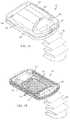
- FIG. 1Ais a schematic perspective view of a skin blister harvesting device according to the invention.
- FIG. 1Bis a schematic perspective view of a base portion of the skin blister harvesting device of FIG. 1A ;
- FIG. 2Ais a schematic side view of a harvester device with a sensor system according to one embodiment of the invention
- FIG. 2Bis a schematic cross-sectional view of the harvester device of FIG. 2A ;
- FIG. 3is a schematic illustration of a sensor system employing a transmitter and receivers prior to blister formation
- FIG. 4is a schematic illustration of the sensor system of FIG. 3 detecting the formation of a blister
- FIG. 5is a schematic illustration of a pattern of transmitter and receiver elements that can reduce the number of transmitters
- FIG. 6is a schematic illustration of an alternative pattern of transmitters.
- FIG. 7is a schematic illustration of only the transmitter elements in the pattern of FIG. 5 ;
- FIGS. 8 and 9are schematic illustrations of an alternative sensor system based on load sensing
- FIG. 8illustrates the load sensor prior to blister formation
- FIG. 9is a schematic illustration of a load sensor detecting the formation of a blister
- FIGS. 10 and 11are schematic illustrations of an alternative sensor system based on distance sensing
- FIG. 10illustrates the distance sensor prior to blister formation
- FIG. 11is a schematic illustration of a distance sensor detecting the presence of a blister
- FIG. 12is a schematic illustration of a color sensor detecting the presence of a blister
- FIG. 13Ais a schematic illustration of a controller display showing a user interface for selecting a desired blister height
- FIG. 13Bis a schematic illustration of a controller display showing a user interface for selecting a desired blister fill factor.
- FIG. 13Cis a schematic illustration of a controller display showing a user interface for showing progress in successful blister formation.
- the present inventiongenerally relates to sensor systems for use in devices that can raise a blister (e.g., a suction blister) and cut the raised blister, i.e., a blister raising device integrated with a cutting member.
- a blistere.g., a suction blister
- Such devicesare useful for harvesting skin grafts.
- the devices and systemsare adapted to infuse a fluid into skin at a donor site to enhance blister formation.
- the devices according to the inventioninclude a head portion that can be removably coupled to a harvester body that is positioned at the donor site of a subject's skin.
- the head portion and the body portiondefine a sealed chamber therebetween so that a fluid can be instilled and removed, and so that negative pressure can be applied to skin following fluid infusion.
- the coupler or conduit for fluid delivery and evacuation of the chambercan be part of either the head portion or the body portion and that the fluid and negative pressure can be applied separately via multiple couplings or via a single conduit as illustrated.
- FIG. 1Ais a schematic view of a skin graft harvester 50 for use in accordance with various aspects of the present teachings.
- the harvest 50includes a detachable head portion 52 and harvester body 54 .
- the harvester body 54is adapted for placement on a patient's skin at a donor site where skin grafts are to be obtained, e.g., on the inner thigh, and secured in place, for example, with strap 56 (shown in phantom).
- the head 52can further include a heater (not shown) powered via a coupler 60 adapted to couple with a power source in a base unit (not shown).
- the head 52further includes a seal 63 which permits a reduced pressure chamber to be formed when the head 52 and body 54 are joined together and the harvester 50 is coupled to a vacuum pump or other source of reduced pressure, e.g., via coupler 60 connecting the harvester 50 to its base unit.
- the head 52can further include one or more windows 58 for observation of skin blisters being formed within the chamber by application of reduced pressure, heat or both. Once the blisters have been formed, the head 52 can be removed, e.g., by deactivating the source of reduced pressure and by actuation of release levers 62 , which break the seal 63 and allow the head 52 to be lifted off the harvester body 54 .
- FIG. 1Bis a schematic view of the skin graft harvester 50 of FIG. 1A with the head 52 removed and the cutting mechanism 74 exposed.
- the harvester body 54can include a base portion 70 , a sled 72 , and actuator handle 80 .
- the cutting mechanism 74can include a plurality of plates with initially aligned holes through which skin blisters are drawn by heat and/or application of suction when the head 52 is joined to the harvester body 54 and activated. Once the blisters are formed, they can be cleaved by the cutting mechanism 74 .
- one or more additional platese.g., a cutter plate and a bottom plate can be deployed with aligned holes.
- the sled 72By actuation (e.g., pulling up) of handle 80 , the sled 72 is caused to move horizontally such that one of the plates below the top plate, e.g., the “cutter plate” (not shown) also moves (because of its linkage to the sled 72 ), thereby occluding the alignment of holes 78 and cleaving the raised blisters from the donor's skin.
- the sled 72By actuation (e.g., pulling up) of handle 80 , the sled 72 is caused to move horizontally such that one of the plates below the top plate, e.g., the “cutter plate” (not shown) also moves (because of its linkage to the sled 72 ), thereby occluding the alignment of holes 78 and cleaving the raised blisters from the donor's skin.
- the sensor systems of the present inventioncan be incorporated into either the harvester head 52 or harvester body 54 —or both.
- FIGS. 2A and 2Bare schematic illustrations of harvester device 50 having a cutter mechanism 74 in contact with a donor site of a patient's skin 2 and equipped with a non-contact blister sensor 10 to reduce burden and variability in deciding when a skin graft is ready to be harvested.
- the sensoris connected (e.g., by a wired connection 13 or wireless path via transceiver 11 ) to a controller 100 which can be part of the harvester or situated remotely (e.g., as part of the console that provides a source of negative pressure and/or current to heater elements (not shown) within the harvester.
- the controller 100can be a dedicated device or a software application on general purpose computer, laptop, tablet or smart phone type device.
- the wireless connectioncan operate via a Bluetooth or other communication protocol.
- the sensor 10can be constructed of a matrix of non-contact proximity sensor elements (e.g., utilizing technology such as infrared or laser optics).
- the sensor elementscan include emitters 12 and receivers 14 .
- the sensor elementsare disposed above or integrated into the cutting mechanism 74 . When initially deployed the cutter mechanism has a plurality of align holes, through which skin blisters will be drawn by suction, heating or other manner.
- each emitter 12produces a signal 16 that can be received by a receiver 14 .
- emitter 12can be paired with multiple sensors, e.g., receivers 14 A and 14 B.
- receivers 14 A and 14 BSensortec Systems
- receiver 14 Adoes not receive an expected signal ( FIG. 4 ) it can be assumed that the direct line of travel between the emitter 12 and receiver 14 A has been broken and that therefore the blister 4 has achieved a sufficient height to be ready for harvesting.
- the signalcan be a continuous beam or a series of timed pulses to reduce power consumption (and also limit irradiation of skin as well as the graft to be harvested).
- the systemcan be configured to ensure that a pre-assigned number of paired sensor arrangements (emitter and receiver) are in a ‘ready’ state before giving an alert to the user that the site is ready for harvesting.
- the devicecan instruct the user of this status.
- the systemmay even indicate the next steps in the process.
- the sensorscan be contact sensors.
- load sensorscan be placed above each harvest orifice ( FIG. 8 ); or at predetermined sites to minimize cost.
- the devicecan alert the user that the skin is ready for harvesting.
- the systemmay need to periodically raise and lower the load sensors ( FIG. 9 ) to avoid interference with blister formation during the application of negative pressure within the chamber.
- conductivity sensorscan be used in lieu of (or in conjunction with) load sensors.
- the sensorcan be a conduction touch panel that can be placed within the harvester (or at predetermined positions). Once in contact with the skin in an acceptable number of locations or total area, the device can alert the user that the skin is ready for harvesting.
- the capacitive sensormay need to be periodically raised and lowered.
- the sensorscan be distance sensing sensors.
- a sensore.g., an emitter and receiver pair
- the distance sensor 94By recording the time it takes for the signal to return to the distance sensor 94 ( FIG. 10 ), the distance from the emitter and the top of the blister 4 can be calculated. When this hits a predetermined time, the skin is ready for harvesting ( FIG. 11 ).
- a single emitter and multiple receiverscan be employed. Alternatively, multiple emitters and a single receiver can be used. The signals from the receiver(s) can be multiplexed or averaged to determine when a sufficient number of holes have been filled with blisters ready for harvesting.
- the senorcan employ “volume sensing” techniques. For example, ultrasound can be used to produce a volume representation of the cavity in which the blisters are being pulled within the system. This can then be used to calculate the volume of the blisters by subtracting the measured volume from the start volume. When the ultrasound signal reaches a predetermined threshold the device can alert the user that the skin is ready for harvesting. Alternatively, changes in the volume of the chamber can be determined by deadspace leak detection. By utilizing the vacuum source, the cavity in which the blisters are being formed can periodically be vented. If the leak within the cavity is known, then utilizing the time it takes for the cavity pressure to hit a predetermined threshold the system can calculate the volume of the blisters that are protruding through the harvester and alert the user the skin is ready for harvesting.
- volume sensingFor example, ultrasound can be used to produce a volume representation of the cavity in which the blisters are being pulled within the system. This can then be used to calculate the volume of the blisters by subtracting the measured volume from the start volume. When the ultrasound signal
- the sensorcan be a colorimetric sensor 120 capable of detecting changes in color, e.g., in a plate having the holes through which the blisters will be raised.
- the sensorcan include a color photo detector 122 (or an array of such detectors) and an optional lens 124 (for widening the view of view).
- a controller associate with the sensorcan alert the user that the skin graft(s) are ready for harvesting—or automatically initiate steps to cut the blister(s).
- the colorimetercan further include filters 126 to preferentially pass colors associated with skin tones (or skin components such as melanin).
- the detectorcan be deployed within the device's chamber. Alternatively, light from the chamber can be collected via a waveguide or optical fiber (or fiber bundle) and transmitted to a detector outside of the device.
- the device/sensorcan be configured to allow the user to define the blister height before initiating graft formation. This can be done mechanically by adjusting the space between the sensor and the forming hole, or electronically by adjusting the calibration of the sensor for proximity, pressure, reflection, time to receive a sound wave, etc.
- the controller 100e.g., a smartphone app, can communicate with the sensor to select a desired height.
- the device/sensorcan also be configured to allow the user to define the minimal number of successfully formed grafts that need to be formed before alerting the clinician that the grafts are ready (50%, 70%, 100%).
- the devicecan count the number of grafts formed and either display as a total, a percentage of the total, or in a light grid pattern (one light for each graft, changing from red to green when formed). This allows the user to decide if they have enough grafts and in the pattern/orientation suitable for them.
- the controller 100e.g., a smartphone app, can communicate with the sensor to select a desired fill factor to be obtained or, as shown in FIG. 13C , the controller 100 can monitor and display the progress of blister formation so that the user can determine when to initiate graft formation.
- load sensoris intended to encompass pressure transducers, touch sensors, piezometers and other piezoelectric devices, force sensors, force sensing variable resistors and/or capacitors and like devices which can determine pressure or contact based on changes in force or electrical or magnetic behavior.
- conductivity sensoris intended to encompass devices that can measure or determine changes in light, electrical resistance, capacitance and/or impedance, associated with the presence of skin within or near a target site.
- proximityencompasses situations wherein objects are close to each other as well situations where objects are in contact with each other. Closeness is not absolute quantity but rather denotes a distance wherein an object, e.g., a sensor, can perform its intended function.
Landscapes
- Health & Medical Sciences (AREA)
- Surgery (AREA)
- Life Sciences & Earth Sciences (AREA)
- Heart & Thoracic Surgery (AREA)
- Nuclear Medicine, Radiotherapy & Molecular Imaging (AREA)
- Engineering & Computer Science (AREA)
- Biomedical Technology (AREA)
- Medical Informatics (AREA)
- Molecular Biology (AREA)
- Animal Behavior & Ethology (AREA)
- General Health & Medical Sciences (AREA)
- Public Health (AREA)
- Veterinary Medicine (AREA)
- Transplantation (AREA)
- Plastic & Reconstructive Surgery (AREA)
- Measuring And Recording Apparatus For Diagnosis (AREA)
Abstract
Description
Claims (23)
Priority Applications (1)
| Application Number | Priority Date | Filing Date | Title |
|---|---|---|---|
| US16/000,889US11058453B2 (en) | 2013-12-31 | 2018-06-06 | Sensor systems for skin graft harvesting |
Applications Claiming Priority (3)
| Application Number | Priority Date | Filing Date | Title |
|---|---|---|---|
| US201361922432P | 2013-12-31 | 2013-12-31 | |
| US14/581,560US9993261B2 (en) | 2013-12-31 | 2014-12-23 | Sensor systems for skin graft harvesting |
| US16/000,889US11058453B2 (en) | 2013-12-31 | 2018-06-06 | Sensor systems for skin graft harvesting |
Related Parent Applications (1)
| Application Number | Title | Priority Date | Filing Date |
|---|---|---|---|
| US14/581,560DivisionUS9993261B2 (en) | 2013-12-31 | 2014-12-23 | Sensor systems for skin graft harvesting |
Publications (2)
| Publication Number | Publication Date |
|---|---|
| US20190038303A1 US20190038303A1 (en) | 2019-02-07 |
| US11058453B2true US11058453B2 (en) | 2021-07-13 |
Family
ID=52350375
Family Applications (2)
| Application Number | Title | Priority Date | Filing Date |
|---|---|---|---|
| US14/581,560Active2036-03-16US9993261B2 (en) | 2013-12-31 | 2014-12-23 | Sensor systems for skin graft harvesting |
| US16/000,889Active2036-03-10US11058453B2 (en) | 2013-12-31 | 2018-06-06 | Sensor systems for skin graft harvesting |
Family Applications Before (1)
| Application Number | Title | Priority Date | Filing Date |
|---|---|---|---|
| US14/581,560Active2036-03-16US9993261B2 (en) | 2013-12-31 | 2014-12-23 | Sensor systems for skin graft harvesting |
Country Status (3)
| Country | Link |
|---|---|
| US (2) | US9993261B2 (en) |
| EP (3) | EP3089682B1 (en) |
| WO (1) | WO2015103043A1 (en) |
Families Citing this family (8)
| Publication number | Priority date | Publication date | Assignee | Title |
|---|---|---|---|---|
| US9451979B2 (en) | 2008-09-24 | 2016-09-27 | The General Hospital Corporation | Method and apparatus for grafting of skin tissue |
| US9597111B2 (en) | 2010-08-06 | 2017-03-21 | Kci Licensing, Inc. | Methods for applying a skin graft |
| WO2013066426A2 (en) | 2011-06-24 | 2013-05-10 | Kci Licensing, Inc. | Reduced-pressure dressings employing tissue-fixation elements |
| US10912861B2 (en) | 2015-04-09 | 2021-02-09 | Kci Licensing, Inc. | Soft-tack, porous substrates for harvesting skin grafts |
| EP3370630B1 (en) | 2015-11-03 | 2021-06-16 | 3M Innovative Properties Company | Device for creating an epidermal graft sheet |
| US20200163688A1 (en)* | 2017-07-12 | 2020-05-28 | Kci Licensing, Inc. | Ac impedance sensor systems for skin graft harvesting |
| WO2019148149A1 (en)* | 2018-01-29 | 2019-08-01 | Kci Licensing, Inc. | Epidermal harvester with integrated mechanical stretching mechanism |
| US11344328B2 (en)* | 2019-09-19 | 2022-05-31 | Tara Medical Devices, LLC | Devices, systems, and methods for epidermal tissue harvesting |
Citations (5)
| Publication number | Priority date | Publication date | Assignee | Title |
|---|---|---|---|---|
| US20020169394A1 (en)* | 1993-11-15 | 2002-11-14 | Eppstein Jonathan A. | Integrated tissue poration, fluid harvesting and analysis device, and method therefor |
| US20120035619A1 (en)* | 2010-08-06 | 2012-02-09 | MoMelan Technologies, Inc. | Methods for applying a skin graft |
| US20120172894A1 (en)* | 2010-08-06 | 2012-07-05 | MoMelan Technologies, Inc. | Devices for harvesting a skin graft |
| US20130145596A1 (en)* | 2011-12-07 | 2013-06-13 | MoMelan Technologies, Inc. | Methods of manufacturing devices for generating skin grafts |
| US20130204273A1 (en)* | 2010-08-06 | 2013-08-08 | MoMelan Technologies, Inc. | Microblister skin grafting |
Family Cites Families (126)
| Publication number | Priority date | Publication date | Assignee | Title |
|---|---|---|---|---|
| US2579039A (en) | 1943-05-17 | 1951-12-18 | Us Electrical Motors Inc | Lubricating system |
| US2379574A (en) | 1943-11-05 | 1945-07-03 | Claude R Wickard | Method of producing surgical bandages with improved elastic properties |
| US2721555A (en) | 1952-12-03 | 1955-10-25 | John A Jenney | Dermatome |
| US3054404A (en) | 1961-08-14 | 1962-09-18 | Cicero P Meek | Skin graft applicator |
| US3782387A (en) | 1972-02-29 | 1974-01-01 | R Falabella | Apparatus and methods for obtaining and making skin grafts |
| US4345374A (en) | 1974-01-14 | 1982-08-24 | The Gillette Company | Razor with means to adjust blade geometry |
| SU772544A1 (en) | 1979-01-04 | 1980-10-23 | Тартусский Ордена Трудового Красного Знамени Государственный Университет | Dermatome |
| DE3371743D1 (en) | 1982-07-21 | 1987-07-02 | Smith & Nephew Ass | Adhesive wound dressing |
| DE3247387C2 (en) | 1982-12-22 | 1984-11-22 | Rolf Prof. Dr.med. 7400 Tübingen Hettich | Method for producing a transplant and device for carrying out the method |
| US4605010A (en) | 1984-05-17 | 1986-08-12 | Western Clinical Engineering Ltd. | Pressurizing cuff |
| GB8428921D0 (en) | 1984-11-15 | 1984-12-27 | Gillette Co | Safety razor blades |
| US4600533A (en) | 1984-12-24 | 1986-07-15 | Collagen Corporation | Collagen membranes for medical use |
| US4666447A (en) | 1985-01-30 | 1987-05-19 | Mentor Corporation | Skin expansion device and method of making the same |
| US5460939A (en) | 1986-04-18 | 1995-10-24 | Advanced Tissue Sciences, Inc. | Temporary living skin replacement |
| US5015584A (en) | 1987-10-14 | 1991-05-14 | Board Of Regents, The University Of Texas System | Epidermal graft system |
| US4917086A (en) | 1988-05-26 | 1990-04-17 | Snyder Laboratories, Inc. | Dermatome blade assembly |
| IE911869A1 (en) | 1990-06-01 | 1991-12-04 | Regeneron Pharma | A family of map2 protein kinases |
| SE9101022D0 (en) | 1991-01-09 | 1991-04-08 | Paal Svedman | MEDICAL SUSPENSION DEVICE |
| US5163955A (en) | 1991-01-24 | 1992-11-17 | Autogenics | Rapid assembly, concentric mating stent, tissue heart valve with enhanced clamping and tissue alignment |
| US6503277B2 (en) | 1991-08-12 | 2003-01-07 | Peter M. Bonutti | Method of transplanting human body tissue |
| US5329846A (en) | 1991-08-12 | 1994-07-19 | Bonutti Peter M | Tissue press and system |
| US6436078B1 (en) | 1994-12-06 | 2002-08-20 | Pal Svedman | Transdermal perfusion of fluids |
| CN2125374U (en) | 1992-06-12 | 1992-12-23 | 王诚 | Negative pressure type skin auto-grafting apparatus |
| US6315772B1 (en) | 1993-09-24 | 2001-11-13 | Transmedica International, Inc. | Laser assisted pharmaceutical delivery and fluid removal |
| US5386633A (en) | 1993-12-27 | 1995-02-07 | Kanno; Yukio | Hamburger patty knife with blade attachment |
| US5476478A (en) | 1994-04-18 | 1995-12-19 | Providence Hospital | Preoperative skin stretching apparatus and method |
| US5489304A (en) | 1994-04-19 | 1996-02-06 | Brigham & Women's Hospital | Method of skin regeneration using a collagen-glycosaminoglycan matrix and cultured epithelial autograft |
| AU697233B2 (en) | 1994-04-21 | 1998-10-01 | Medchem Products, Inc. | Skin stretching device |
| US5496339A (en) | 1994-05-17 | 1996-03-05 | Koepnick; Russell G. | Universal automated keratectomy apparatus and method |
| US5433221A (en) | 1994-10-05 | 1995-07-18 | Adair; Edwin L. | Windowed self-centering drape for surgical camera |
| US5571098A (en) | 1994-11-01 | 1996-11-05 | The General Hospital Corporation | Laser surgical devices |
| US20030152909A1 (en) | 1994-11-16 | 2003-08-14 | Mitrani Eduardo N. | In vitro micro-organs, and uses related thereto |
| US5595570A (en) | 1994-12-06 | 1997-01-21 | S.C.M.D., Ltd. | Keratome with spring loaded adjustable plate, cutting length adjustment plate, method of cutting a corneal flap, and gauge-mounted bracket for adjusting plate on keratome head |
| US5520635A (en) | 1994-12-16 | 1996-05-28 | Gelbfish; Gary A. | Method and associated device for removing clot |
| US5686303A (en) | 1994-12-30 | 1997-11-11 | Korman; Joshua | Method of growing vertebrate skin in vitro |
| US6693077B1 (en) | 1995-02-14 | 2004-02-17 | Human Genome Sciences, Inc. | Keratinocyte growth factor-2 |
| GB9508606D0 (en) | 1995-04-27 | 1995-06-14 | Svedman Paul | Suction blister sampling |
| US5817115A (en) | 1995-12-04 | 1998-10-06 | Chiron Vision Corporation | Apparatus for resecting corneal tissue |
| US6080166A (en) | 1995-12-05 | 2000-06-27 | Mcewen; James Allen | Direct linear drive dermatome |
| IL116282A (en) | 1995-12-07 | 2000-10-31 | L R Surgical Instr Ltd | Adjustable mesher device and a system for using the same |
| US6071247A (en) | 1996-07-21 | 2000-06-06 | Kennedy; William R. | Skin blister biopsy apparatus and method |
| NL1004276C2 (en) | 1996-10-15 | 1998-04-20 | Willem Marie Ysebaert | Methods for manufacturing skin islets, for moving skin or islets, for spreading skin isles and applying them to a burn, as well as a holder, cutting frame, cutting table, counter carrier, clamping member, membrane, transporter and spreader for use in such methods. |
| US6626901B1 (en) | 1997-03-05 | 2003-09-30 | The Trustees Of Columbia University In The City Of New York | Electrothermal instrument for sealing and joining or cutting tissue |
| JP2002507908A (en) | 1997-06-26 | 2002-03-12 | スミス アンド ネフュー ピーエルシー | Cell culture products |
| US6610075B1 (en) | 1997-10-24 | 2003-08-26 | Becton, Dickenson And Company | Keratome with suspended stabilized blade, improved suction ring with applanator and guided engagement with keratome cutter head, automated translation of the cutter head, and blade insertion tool |
| US5972476A (en) | 1997-11-21 | 1999-10-26 | Means Industries, Inc. | Laminated parts and method of making same |
| US5921980A (en) | 1997-12-03 | 1999-07-13 | University Of Kentucky Research Foundation | Laser skin graft harvesting apparatus and related method |
| US6071267A (en) | 1998-02-06 | 2000-06-06 | Kinetic Concepts, Inc. | Medical patient fluid management interface system and method |
| US6358260B1 (en) | 1998-04-20 | 2002-03-19 | Med-Logics, Inc. | Automatic corneal shaper with two separate drive mechanisms |
| US7540875B2 (en) | 1998-06-01 | 2009-06-02 | Avatar Design & Development, Inc. | Surgical cutting tool with automatically retractable blade assembly |
| US6402770B1 (en) | 1998-06-01 | 2002-06-11 | Avatar Design & Development, Inc. | Method and apparatus for placing and maintaining a percutaneous tube into a body cavity |
| US6599305B1 (en) | 1998-08-12 | 2003-07-29 | Vladimir Feingold | Intracorneal lens placement method and apparatus |
| US6083236A (en) | 1998-08-12 | 2000-07-04 | Feingold; Vladimir | Keratome method and apparatus |
| US6165189A (en) | 1999-02-10 | 2000-12-26 | Sis, Ltd. | Microkeratome for performing lasik surgery |
| AU3508600A (en) | 1999-02-26 | 2000-09-14 | Orchid Biosciences, Inc. | Microstructures for use in biological assays and reactions |
| IL138710A0 (en) | 1999-10-15 | 2001-10-31 | Newman Martin H | Atomically sharp edge cutting blades and method for making same |
| US6612310B2 (en) | 2000-06-22 | 2003-09-02 | Oec Medical Systems, Inc. | Windowed medical drape |
| WO2003059154A2 (en) | 2002-01-15 | 2003-07-24 | I.V. House, Inc. | Site guard for intravenous sites and other sensitive areas |
| DE10051215A1 (en) | 2000-10-16 | 2002-05-08 | Gebauer Gmbh | Blade with amorphous cutting edge |
| US6629983B1 (en) | 2000-10-27 | 2003-10-07 | Edge Systems Corporation | Apparatus and method for skin/surface abrasion |
| US7078582B2 (en) | 2001-01-17 | 2006-07-18 | 3M Innovative Properties Company | Stretch removable adhesive articles and methods |
| US7651507B2 (en) | 2003-03-03 | 2010-01-26 | Kci Licensing, Inc. | Tissue processing system |
| US7666192B2 (en) | 2001-02-16 | 2010-02-23 | Kci Licensing, Inc. | Skin grafting devices and methods |
| US20040030263A1 (en) | 2001-08-29 | 2004-02-12 | Artemis Medical, Inc. | Undamaged tissue collection assembly and method |
| US7513902B2 (en) | 2001-10-01 | 2009-04-07 | The Cleveland Clinic Foundation | Skin lesion exciser and skin-closure device therefor |
| KR100969344B1 (en) | 2001-11-05 | 2010-07-09 | 메드제닉스 인코포레이티드 | Closed automated system for tissue-based treatment, methods of dosing and administering using the same |
| US7468242B2 (en) | 2001-11-05 | 2008-12-23 | Medgenics, Inc. | Dermal micro organs, methods and apparatuses for producing and using the same |
| US8466116B2 (en) | 2001-12-20 | 2013-06-18 | The Unites States Of America As Represented By The Secretary Of The Department Of Health And Human Services | Use of CpG oligodeoxynucleotides to induce epithelial cell growth |
| AU2002254183A1 (en) | 2002-01-18 | 2003-09-04 | John M. Levin | Force-transmission-control system and devices employing same |
| DE10209122B4 (en) | 2002-03-01 | 2006-04-13 | Fleischmann, Wilhelm, Dr.med. | Instrument for tissue dilation of the skin |
| EP1549738B1 (en) | 2002-04-30 | 2010-04-21 | Stratatech Corporation | Keratinocytes expressing exogenous angiogenic growth factors |
| US20030212357A1 (en) | 2002-05-10 | 2003-11-13 | Pace Edgar Alan | Method and apparatus for treating wounds with oxygen and reduced pressure |
| US7666134B2 (en) | 2002-09-28 | 2010-02-23 | Kci Licensing, Inc. | System and method for transplantation of dermal tissue |
| US7964390B2 (en) | 2002-10-11 | 2011-06-21 | Case Western Reserve University | Sensor system |
| US7976519B2 (en) | 2002-12-31 | 2011-07-12 | Kci Licensing, Inc. | Externally-applied patient interface system and method |
| CA2515501A1 (en) | 2003-02-10 | 2004-08-26 | Applied Tissue Technologies, Llc | Apparatus for dermal tissue harvesting |
| CN2596950Y (en) | 2003-02-24 | 2004-01-07 | 孙文红 | Epiderm extraction apparatus |
| US7708746B2 (en) | 2003-02-27 | 2010-05-04 | Wright Medical Technology, Inc. | Method and apparatus for processing dermal tissue |
| AU2004215916B2 (en) | 2003-02-27 | 2010-07-29 | Applied Tissue Technologies, Llc | Method and apparatus for processing dermal tissue |
| US20040175690A1 (en) | 2003-03-03 | 2004-09-09 | Kci Licensing, Inc. | Tissue harvesting device and method |
| US7285576B2 (en) | 2003-03-12 | 2007-10-23 | 3M Innovative Properties Co. | Absorbent polymer compositions, medical articles, and methods |
| US20040181950A1 (en) | 2003-03-17 | 2004-09-23 | Rodgers Murray Steven | Alignment of microkeratome blade to blade handle |
| US7137979B2 (en) | 2003-05-31 | 2006-11-21 | Tyrell, Inc. | Methods and devices for the treatment of skin lesions |
| US6997092B2 (en) | 2003-06-02 | 2006-02-14 | Chau Lih Rong Enterprise Co., Ltd. | Cutting apparatus |
| US10583220B2 (en) | 2003-08-11 | 2020-03-10 | DePuy Synthes Products, Inc. | Method and apparatus for resurfacing an articular surface |
| US20050101972A1 (en) | 2003-11-06 | 2005-05-12 | University Of Florida Research Foundation, Inc. | Devices and systems for separating and preparing skin |
| EP1729677B1 (en) | 2004-03-31 | 2010-04-21 | Cook Incorporated | Graft material and stent graft comprising extracellular collagen matrix and method of preparation |
| US7790945B1 (en) | 2004-04-05 | 2010-09-07 | Kci Licensing, Inc. | Wound dressing with absorption and suction capabilities |
| US20050244967A1 (en) | 2004-05-03 | 2005-11-03 | Pearlman Andrew L | Closed automated system for tissue based therapy |
| US8932233B2 (en) | 2004-05-21 | 2015-01-13 | Devicor Medical Products, Inc. | MRI biopsy device |
| US8079969B2 (en) | 2004-06-09 | 2011-12-20 | Benny Rousso | Portable self-contained device for enhancing circulation |
| TWI270362B (en) | 2004-12-28 | 2007-01-11 | Ind Tech Res Inst | Cell subcloning device |
| US20060287696A1 (en) | 2005-06-21 | 2006-12-21 | Wright David W | Heat and light therapy treatment device and method |
| US20090036795A1 (en) | 2005-09-26 | 2009-02-05 | Koninklijke Philips Electronics, N.V. | Substance sampling and/or substance delivery via skin |
| US8568333B2 (en) | 2006-05-01 | 2013-10-29 | Devicor Medical Products, Inc. | Grid and rotatable cube guide localization fixture for biopsy device |
| FR2904103B1 (en) | 2006-07-18 | 2015-05-15 | Airbus France | HEAT FLOW DEVICE |
| US8579852B2 (en) | 2006-09-14 | 2013-11-12 | Omeed Memar | Apparatus and methods for repairing tissue defects |
| CN101053528A (en) | 2007-06-01 | 2007-10-17 | 张磊 | Suction nozzle capable of separating large surface of skin |
| US7946585B2 (en) | 2007-09-26 | 2011-05-24 | T.E. Brangs, Inc. | Mechanical ball projection game devices |
| GB2453308B (en) | 2007-10-03 | 2012-07-25 | Acell Group Ltd | Composite products |
| JP4899019B2 (en) | 2007-10-17 | 2012-03-21 | アルケア株式会社 | Wound dressing and its manufacturing method |
| US8002779B2 (en) | 2007-12-13 | 2011-08-23 | Zimmer Surgical, Inc. | Dermatome blade assembly |
| US20110251602A1 (en) | 2008-04-01 | 2011-10-13 | The General Hospital Corporation | Method and apparatus for tissue expansion |
| CN102119006B (en) | 2008-04-01 | 2017-09-26 | 通用医疗公司 | Methods and devices for tissue transplantation |
| US20100043694A1 (en) | 2008-08-20 | 2010-02-25 | Patel Gordhanbhai N | Tamper evident indicating devices |
| US9451979B2 (en)* | 2008-09-24 | 2016-09-27 | The General Hospital Corporation | Method and apparatus for grafting of skin tissue |
| US8784385B2 (en) | 2008-10-31 | 2014-07-22 | The Invention Science Fund I, Llc | Frozen piercing implements and methods for piercing a substrate |
| PT2256061E (en) | 2009-05-30 | 2012-05-07 | Bayer Innovation Gmbh | Product with bioreabsorbent carrier materials and packaging |
| CN102695528B (en) | 2009-08-21 | 2016-07-13 | 诺万公司 | Wound dressing, its using method and forming method thereof |
| US20110077664A1 (en) | 2009-09-28 | 2011-03-31 | Wright Medical Technology, Inc. | Device for processing dermal tissue |
| WO2011059441A1 (en) | 2009-11-13 | 2011-05-19 | Smith & Nephew, Inc. | Mesher |
| US8900181B2 (en) | 2009-12-18 | 2014-12-02 | Srgi Holdings, Llc | Skin treatment and drug delivery device |
| US9061095B2 (en) | 2010-04-27 | 2015-06-23 | Smith & Nephew Plc | Wound dressing and method of use |
| US20120021186A1 (en) | 2010-06-07 | 2012-01-26 | Uwe Schneider | Seam structure and method for making a seam |
| US8926631B2 (en)* | 2010-08-06 | 2015-01-06 | MoMelan Technologies, Inc. | Methods for preparing a skin graft without culturing or use of biologics |
| US8617181B2 (en) | 2010-08-06 | 2013-12-31 | MoMelan Technologies, Inc. | Methods for preparing a skin graft |
| US8562626B2 (en)* | 2010-08-06 | 2013-10-22 | MoMelan Technologies, Inc. | Devices for harvesting a skin graft |
| US8226663B2 (en)* | 2010-09-22 | 2012-07-24 | Irina Remsburg | Microdermabrasion hand piece providing automatic limitation of skin hyperextension |
| US20120197267A1 (en)* | 2011-01-27 | 2012-08-02 | MoMelan Technologies, Inc. | Devices for generating and transferring micrografts and methods of use thereof |
| WO2012145504A1 (en) | 2011-04-20 | 2012-10-26 | Kci Licensing, Inc. | Skin graft devices and methods |
| US20130041385A1 (en) | 2011-08-10 | 2013-02-14 | Joseph Giovannoli | Apparatus for skin reduction |
| PT2780073T (en) | 2011-11-15 | 2017-12-18 | Neurometrix Inc | Apparatus for relieving pain using transcutaneous electrical nerve stimulation |
| CN103402468A (en) | 2012-03-01 | 2013-11-20 | 爱乐康株式会社 | wound care supplies |
| EP2846871A4 (en) | 2012-05-09 | 2016-01-27 | Medoc Ltd | Improved thermal stimulation probe and method |
| EP3289988A1 (en) | 2013-03-14 | 2018-03-07 | KCI Licensing, Inc. | Absorbent substrates for harvesting skin grafts |
| US10463392B2 (en) | 2013-12-31 | 2019-11-05 | Kci Licensing, Inc. | Fluid-assisted skin graft harvesting |
- 2014
- 2014-12-23WOPCT/US2014/072180patent/WO2015103043A1/enactiveApplication Filing
- 2014-12-23EPEP14827680.1Apatent/EP3089682B1/enactiveActive
- 2014-12-23EPEP19201750.7Apatent/EP3626188B1/enactiveActive
- 2014-12-23EPEP17166935.1Apatent/EP3243453B1/ennot_activeNot-in-force
- 2014-12-23USUS14/581,560patent/US9993261B2/enactiveActive
- 2018
- 2018-06-06USUS16/000,889patent/US11058453B2/enactiveActive
Patent Citations (5)
| Publication number | Priority date | Publication date | Assignee | Title |
|---|---|---|---|---|
| US20020169394A1 (en)* | 1993-11-15 | 2002-11-14 | Eppstein Jonathan A. | Integrated tissue poration, fluid harvesting and analysis device, and method therefor |
| US20120035619A1 (en)* | 2010-08-06 | 2012-02-09 | MoMelan Technologies, Inc. | Methods for applying a skin graft |
| US20120172894A1 (en)* | 2010-08-06 | 2012-07-05 | MoMelan Technologies, Inc. | Devices for harvesting a skin graft |
| US20130204273A1 (en)* | 2010-08-06 | 2013-08-08 | MoMelan Technologies, Inc. | Microblister skin grafting |
| US20130145596A1 (en)* | 2011-12-07 | 2013-06-13 | MoMelan Technologies, Inc. | Methods of manufacturing devices for generating skin grafts |
Also Published As
| Publication number | Publication date |
|---|---|
| EP3626188B1 (en) | 2021-08-18 |
| US20150182242A1 (en) | 2015-07-02 |
| US20190038303A1 (en) | 2019-02-07 |
| EP3243453B1 (en) | 2019-10-09 |
| EP3626188A1 (en) | 2020-03-25 |
| US9993261B2 (en) | 2018-06-12 |
| EP3089682A1 (en) | 2016-11-09 |
| WO2015103043A1 (en) | 2015-07-09 |
| EP3243453A1 (en) | 2017-11-15 |
| EP3089682B1 (en) | 2017-04-19 |
Similar Documents
| Publication | Publication Date | Title |
|---|---|---|
| US11058453B2 (en) | Sensor systems for skin graft harvesting | |
| AU2010284320B2 (en) | Distributed external and internal wireless sensor systems for characterization of surface and subsurface biomedical structure and condition | |
| AU2016382973B2 (en) | Systems, devices, and methods for performing trans-abdominal fetal oximetry and/or trans-abdominal fetal pulse oximetry | |
| US9101274B2 (en) | Sensor, sensor pad and sensor array for detecting infrasonic acoustic signals | |
| CN102006821B (en) | Device, system and method for modular analyte monitoring | |
| CN108135540B (en) | Non-invasive measurement device for blood glucose levels | |
| US20120302877A1 (en) | Combined ablation and ultrasound imaging | |
| EP2770909B1 (en) | Method and apparatus for calibrating an absolute oxygen saturation sensor | |
| EP2265165A2 (en) | Apparatus for non invasive acoustooptical monitoring | |
| CN110191677A (en) | Detect the erythema as caused by wearable device | |
| US20150359471A1 (en) | Composite medical examination device | |
| US20200163688A1 (en) | Ac impedance sensor systems for skin graft harvesting | |
| US20140303475A1 (en) | Device to Aid in Diagnosing Infiltration or Extravasation in Animalia Tissue | |
| KR102475827B1 (en) | Urine drainage system | |
| US20240285237A1 (en) | Smart intravenous catheter system | |
| US20240307047A1 (en) | Tissue retractor with an integrated optical sensor for pressure measurement | |
| CN207545082U (en) | Monitor bougie and monitoring device | |
| WO2025038755A2 (en) | Devices and methods for active surveillance of shunt-implanted patients |
Legal Events
| Date | Code | Title | Description |
|---|---|---|---|
| FEPP | Fee payment procedure | Free format text:ENTITY STATUS SET TO UNDISCOUNTED (ORIGINAL EVENT CODE: BIG.); ENTITY STATUS OF PATENT OWNER: LARGE ENTITY | |
| AS | Assignment | Owner name:KCI LICENSING, INC., TEXAS Free format text:ASSIGNMENT OF ASSIGNORS INTEREST;ASSIGNORS:PRATT, BENJAMIN A.;LOCKE, CHRISTOPHER BRIAN;ROBINSON, TIMOTHY MARK;AND OTHERS;SIGNING DATES FROM 20150202 TO 20150414;REEL/FRAME:047290/0663 | |
| STPP | Information on status: patent application and granting procedure in general | Free format text:DOCKETED NEW CASE - READY FOR EXAMINATION | |
| STPP | Information on status: patent application and granting procedure in general | Free format text:NON FINAL ACTION MAILED | |
| STPP | Information on status: patent application and granting procedure in general | Free format text:RESPONSE TO NON-FINAL OFFICE ACTION ENTERED AND FORWARDED TO EXAMINER | |
| STPP | Information on status: patent application and granting procedure in general | Free format text:RESPONSE TO NON-FINAL OFFICE ACTION ENTERED AND FORWARDED TO EXAMINER | |
| STPP | Information on status: patent application and granting procedure in general | Free format text:NOTICE OF ALLOWANCE MAILED -- APPLICATION RECEIVED IN OFFICE OF PUBLICATIONS | |
| STPP | Information on status: patent application and granting procedure in general | Free format text:PUBLICATIONS -- ISSUE FEE PAYMENT RECEIVED | |
| STPP | Information on status: patent application and granting procedure in general | Free format text:PUBLICATIONS -- ISSUE FEE PAYMENT VERIFIED | |
| STCF | Information on status: patent grant | Free format text:PATENTED CASE | |
| AS | Assignment | Owner name:3M INNOVATIVE PROPERTIES COMPANY, MINNESOTA Free format text:ASSIGNMENT OF ASSIGNORS INTEREST;ASSIGNOR:KCI LICENSING, INC.;REEL/FRAME:064730/0636 Effective date:20230824 | |
| AS | Assignment | Owner name:SOLVENTUM INTELLECTUAL PROPERTIES COMPANY, MINNESOTA Free format text:ASSIGNMENT OF ASSIGNORS INTEREST;ASSIGNOR:3M INNOVATIVE PROPERTIES COMPANY;REEL/FRAME:066444/0162 Effective date:20240201 | |
| MAFP | Maintenance fee payment | Free format text:PAYMENT OF MAINTENANCE FEE, 4TH YEAR, LARGE ENTITY (ORIGINAL EVENT CODE: M1551); ENTITY STATUS OF PATENT OWNER: LARGE ENTITY Year of fee payment:4 |