US11058407B2 - Trocar cannula assembly and method of manufacture - Google Patents
Trocar cannula assembly and method of manufactureDownload PDFInfo
- Publication number
- US11058407B2 US11058407B2US16/435,300US201916435300AUS11058407B2US 11058407 B2US11058407 B2US 11058407B2US 201916435300 AUS201916435300 AUS 201916435300AUS 11058407 B2US11058407 B2US 11058407B2
- Authority
- US
- United States
- Prior art keywords
- cannula
- balloon
- sleeve
- trocar
- assembly
- Prior art date
- Legal status (The legal status is an assumption and is not a legal conclusion. Google has not performed a legal analysis and makes no representation as to the accuracy of the status listed.)
- Active, expires
Links
Images


Classifications
- A—HUMAN NECESSITIES
- A61—MEDICAL OR VETERINARY SCIENCE; HYGIENE
- A61B—DIAGNOSIS; SURGERY; IDENTIFICATION
- A61B17/00—Surgical instruments, devices or methods
- A61B17/02—Surgical instruments, devices or methods for holding wounds open, e.g. retractors; Tractors
- A61B17/0218—Surgical instruments, devices or methods for holding wounds open, e.g. retractors; Tractors for minimally invasive surgery
- A—HUMAN NECESSITIES
- A61—MEDICAL OR VETERINARY SCIENCE; HYGIENE
- A61B—DIAGNOSIS; SURGERY; IDENTIFICATION
- A61B17/00—Surgical instruments, devices or methods
- A61B17/34—Trocars; Puncturing needles
- A61B17/3417—Details of tips or shafts, e.g. grooves, expandable, bendable; Multiple coaxial sliding cannulas, e.g. for dilating
- B—PERFORMING OPERATIONS; TRANSPORTING
- B29—WORKING OF PLASTICS; WORKING OF SUBSTANCES IN A PLASTIC STATE IN GENERAL
- B29C—SHAPING OR JOINING OF PLASTICS; SHAPING OF MATERIAL IN A PLASTIC STATE, NOT OTHERWISE PROVIDED FOR; AFTER-TREATMENT OF THE SHAPED PRODUCTS, e.g. REPAIRING
- B29C49/00—Blow-moulding, i.e. blowing a preform or parison to a desired shape within a mould; Apparatus therefor
- B29C49/08—Biaxial stretching during blow-moulding
- B—PERFORMING OPERATIONS; TRANSPORTING
- B29—WORKING OF PLASTICS; WORKING OF SUBSTANCES IN A PLASTIC STATE IN GENERAL
- B29D—PRODUCING PARTICULAR ARTICLES FROM PLASTICS OR FROM SUBSTANCES IN A PLASTIC STATE
- B29D23/00—Producing tubular articles
- A—HUMAN NECESSITIES
- A61—MEDICAL OR VETERINARY SCIENCE; HYGIENE
- A61B—DIAGNOSIS; SURGERY; IDENTIFICATION
- A61B17/00—Surgical instruments, devices or methods
- A61B2017/00526—Methods of manufacturing
- A—HUMAN NECESSITIES
- A61—MEDICAL OR VETERINARY SCIENCE; HYGIENE
- A61B—DIAGNOSIS; SURGERY; IDENTIFICATION
- A61B17/00—Surgical instruments, devices or methods
- A61B17/02—Surgical instruments, devices or methods for holding wounds open, e.g. retractors; Tractors
- A61B17/0218—Surgical instruments, devices or methods for holding wounds open, e.g. retractors; Tractors for minimally invasive surgery
- A61B2017/0225—Surgical instruments, devices or methods for holding wounds open, e.g. retractors; Tractors for minimally invasive surgery flexible, e.g. fabrics, meshes, or membranes
- A—HUMAN NECESSITIES
- A61—MEDICAL OR VETERINARY SCIENCE; HYGIENE
- A61B—DIAGNOSIS; SURGERY; IDENTIFICATION
- A61B17/00—Surgical instruments, devices or methods
- A61B17/34—Trocars; Puncturing needles
- A61B2017/348—Means for supporting the trocar against the body or retaining the trocar inside the body
- A61B2017/3482—Means for supporting the trocar against the body or retaining the trocar inside the body inside
- A61B2017/3484—Anchoring means, e.g. spreading-out umbrella-like structure
- A61B2017/3486—Balloon
- A—HUMAN NECESSITIES
- A61—MEDICAL OR VETERINARY SCIENCE; HYGIENE
- A61B—DIAGNOSIS; SURGERY; IDENTIFICATION
- A61B17/00—Surgical instruments, devices or methods
- A61B17/34—Trocars; Puncturing needles
- A61B2017/348—Means for supporting the trocar against the body or retaining the trocar inside the body
- A61B2017/3492—Means for supporting the trocar against the body or retaining the trocar inside the body against the outside of the body
- B—PERFORMING OPERATIONS; TRANSPORTING
- B29—WORKING OF PLASTICS; WORKING OF SUBSTANCES IN A PLASTIC STATE IN GENERAL
- B29K—INDEXING SCHEME ASSOCIATED WITH SUBCLASSES B29B, B29C OR B29D, RELATING TO MOULDING MATERIALS OR TO MATERIALS FOR MOULDS, REINFORCEMENTS, FILLERS OR PREFORMED PARTS, e.g. INSERTS
- B29K2023/00—Use of polyalkenes or derivatives thereof as moulding material
- B—PERFORMING OPERATIONS; TRANSPORTING
- B29—WORKING OF PLASTICS; WORKING OF SUBSTANCES IN A PLASTIC STATE IN GENERAL
- B29K—INDEXING SCHEME ASSOCIATED WITH SUBCLASSES B29B, B29C OR B29D, RELATING TO MOULDING MATERIALS OR TO MATERIALS FOR MOULDS, REINFORCEMENTS, FILLERS OR PREFORMED PARTS, e.g. INSERTS
- B29K2105/00—Condition, form or state of moulded material or of the material to be shaped
- B29K2105/02—Condition, form or state of moulded material or of the material to be shaped heat shrinkable
- B—PERFORMING OPERATIONS; TRANSPORTING
- B29—WORKING OF PLASTICS; WORKING OF SUBSTANCES IN A PLASTIC STATE IN GENERAL
- B29L—INDEXING SCHEME ASSOCIATED WITH SUBCLASS B29C, RELATING TO PARTICULAR ARTICLES
- B29L2023/00—Tubular articles
- B—PERFORMING OPERATIONS; TRANSPORTING
- B29—WORKING OF PLASTICS; WORKING OF SUBSTANCES IN A PLASTIC STATE IN GENERAL
- B29L—INDEXING SCHEME ASSOCIATED WITH SUBCLASS B29C, RELATING TO PARTICULAR ARTICLES
- B29L2031/00—Other particular articles
- B29L2031/753—Medical equipment; Accessories therefor
- B29L2031/7546—Surgical equipment
- B29L2031/7548—Cannulas
- Y—GENERAL TAGGING OF NEW TECHNOLOGICAL DEVELOPMENTS; GENERAL TAGGING OF CROSS-SECTIONAL TECHNOLOGIES SPANNING OVER SEVERAL SECTIONS OF THE IPC; TECHNICAL SUBJECTS COVERED BY FORMER USPC CROSS-REFERENCE ART COLLECTIONS [XRACs] AND DIGESTS
- Y10—TECHNICAL SUBJECTS COVERED BY FORMER USPC
- Y10T—TECHNICAL SUBJECTS COVERED BY FORMER US CLASSIFICATION
- Y10T156/00—Adhesive bonding and miscellaneous chemical manufacture
- Y10T156/10—Methods of surface bonding and/or assembly therefor
- Y10T156/1002—Methods of surface bonding and/or assembly therefor with permanent bending or reshaping or surface deformation of self sustaining lamina
- Y10T156/1043—Subsequent to assembly
- Y10T156/1049—Folding only
Definitions
- This applicationrelates generally to surgical access systems and methods of manufacturing such systems and, more specifically, to balloon trocars with retention components and methods of manufacturing the same.
- Trocar systemsfacilitate minimally invasive surgery across a body wall and within a body cavity.
- trocarsprovide a working channel across the abdominal wall to facilitate the use of instruments within the abdominal cavity.
- Trocar systemstypically include a cannula, which provides the working channel, and an obturator that is used to place the cannula across a body wall, such as the abdominal wall. The obturator is inserted into the working channel of the cannula and pushed through the body wall with a penetration force of sufficient magnitude to result in penetration of the body wall.
- the cannula with an obturatoris passed through an incision formed by the “Hasson,” or cut-down, technique, which includes incremental incisions through the body wall until the body wall is incised through its entire thickness. Once the cannula has traversed the body wall, the obturator can be removed.
- various instrumentsmay be inserted through the cannula into the body cavity.
- One or more cannulaemay be used during a procedure.
- the surgeonmanipulates the instruments in the cannulae, sometimes using more than one instrument at a time.
- the manipulation of an instrument by a surgeonmay cause frictional forces between the instrument and the cannula in which the instrument is inserted. These frictional forces may result in movement of the cannula in an inward or outward direction within the body wall.
- the proximal or distal motions of the instruments through the cannulamay potentially cause the cannula to slip out of the body wall or to protrude further into the body cavity, possibly leading to injury to the patient.
- the surfaces of the cannula associated with a trocarare generally smooth.
- the smoothness of a cannula surfacemakes placement of the cannula through a body wall relatively easy and safe.
- a smooth cannulamay not have the desired retention characteristics once the cannula has been placed through a body wall. This smoothness and ease of placement may present problems as instruments and specimens are removed from a body cavity through the cannula and the associated seal systems of the trocar. It is highly desirable for a cannula to remain fixed in an appropriate position once placed.
- the Hasson techniqueis used, the incision may be larger than the cannula that may be placed through the incision. Therefore, it is desirable to provide a means to seal the incision site after the cannula has been inserted in order to insufflate a patient.
- the cannula fixation or stabilization devicemay include a lower profile and increase the working length of the cannula.
- Methods for achieving the abovecomprise inflatable toroidal balloons that are sized larger than the cannula associated with the access device and usually disposed at or toward the distal end thereof.
- the balloonis deflated.
- the balloonis inflated when the access channel is within the body cavity and properly placed.
- Most of the balloons associated with access devicesare distensible or made of an elastic material. In some cases the balloons are made of a non-distensible or non-elastic material.
- a balloon trocarin various embodiments in accordance with the present invention, can be used in general, abdominal, gynecological and thoracic minimally invasive surgical procedures to establish a path of entry or to gain access through the tissue planes and/or potential spaces for endoscopic instruments.
- a balloon trocarcomprises an inflatable balloon at the distal end of a trocar cannula and a bolster toward the proximal end of the cannula.
- a surgeoninserts the balloon trocar into the body cavity such that the balloon section of the cannula is within the cavity, e.g., for abdominal surgery, beyond the peritoneal lining and within the abdominal cavity.
- the balloonis inflated and the bolster located toward the proximal end of the cannula is moved distally along the length of the cannula in order to compress the balloon against the inside of the body wall and seal the incision. With the bolster against the outer surface of the body wall, the balloon is maintained in compression against the inner surface of the body wall. In this manner, a seal is created between the balloon and the body wall, thereby allowing a surgeon to insufflate a patient.
- the balloonmay remain inflated during the duration of a laparoscopic surgery, which may last up to four hours or more.
- An elastic balloonis formed as a small inflatable structure. When deflated, an elastic balloon assumes a natural “low-profile” condition and conforms to the outer surface of the access channel or cannula.
- a non-elastic balloonis formed to assume a preferred maximum size and shape in a natural condition. Therefore, there exists a surplus of non-elastic balloon material when the balloon is deflated.
- non-elastic balloon structures associated with an access channelthat closely conforms to the exterior of the access channel and minimizes the interference between the deflated balloon and the tissue of a body wall during the insertion of the access device are desirable.
- a balloon trocarin which the balloon or retention component reduces insertion force of the balloon trocar.
- a balloon or expandable membrane positioned on or near the distal end of the cannula of the trocaris void or without or having little air within the balloon and is folded proximally or away from the direction in which the trocar is to be inserted into the body cavity.
- the evacuation of air and folding of the balloonreduces resistance and the insertion force used to insert the cannula within the body cavity without reducing balloon strength to maintain retention by the balloon and integrity of the seal and the balloon itself. Additionally, such a balloon permits the utilization of a reduced insertion force relative to the insertion force of a non-folded balloon.
- a reduced insertion forcepermits a more controlled entry of the trocar into the body cavity.
- a more controlled entryreduces inadvertent and undesirable contact with organs, tissue, other inserted devices or ports within the body cavity.
- a reduced insertion forcereduces potential trauma to the incision or entry site as less force is applied to the site as the trocar is being inserted into the body cavity.
- an access channel or cannulathat is associated with a surgical access device or trocar is provided.
- the cannulais sized and configured to receive a retention and stabilizing balloon along the distal portion.
- a non-elastic balloonmade of polyolefin, nylon, polyester, polyethylene or the like is placed along a location upon the cannula.
- the deflated non-elastic balloonis maintained in the lowest profile condition for insertion through a body wall.
- the balloonconforms very closely the profile of the cannula.
- a folded balloon conditionis maintained.
- a cannula assemblycomprises a cannula and a sleeve.
- the cannulahas a proximal end, a distal end opposite the proximal end, and a lumen extending from the proximal end to the distal end along a longitudinal axis.
- the lumenis configured to receive a surgical instrument therein.
- the cannulacomprises a generally tubular cannula body and an annular recess.
- the generally tubular cannula bodyhas an exterior surface and a first outer diameter.
- the annular recessis formed in the exterior surface of the cannula body adjacent the distal end of the cannula.
- the annular recessis transverse to the longitudinal axis.
- the annular recesshas a second outer diameter smaller than the first outer diameter of the cannula body.
- the sleevehas a proximal end and a distal end.
- the sleeveis disposed around the cannula from adjacent the proximal end of the cannula to the annular recess.
- the sleevecomprises an elongate tubular body, a balloon positioned distal the elongate tubular body, and an annular ring distal the balloon.
- the annular ringis positioned in the annular recess of the cannula.
- the annular ringhas a third inner diameter in an undisturbed state.
- the third inner diameter of the annular ringis smaller than the second outer diameter of the annular recess to define an interference fit between the sleeve and the cannula.
- a cannula assemblycomprises a cannula and a sleeve.
- the cannulahas a proximal end, a distal end opposite the proximal end, and a lumen extending from the proximal end to the distal end along a longitudinal axis.
- the lumenis configured to receive a surgical instrument therein.
- the cannulacomprises a fluid inlet port adjacent the proximal end, a generally tubular cannula body extending from fluid inlet port to the distal end of the cannula, an annular groove formed in the exterior surface of the cannula body adjacent the distal end of the cannula, and a distal tip at the distal end of the cannula body.
- the fluid inlet portcomprises a fluid inlet to receive a source of inflation fluid and a fluid dome fluidly coupled to the fluid inlet.
- the fluid domehas a generally smooth outer surface.
- the cannula bodyhas an exterior surface and a first outer diameter.
- the annular grooveis transverse to the longitudinal axis.
- the annular groovehas a proximal edge, a distal edge, and an annular surface between the proximal edge and the distal edge.
- the annular surfacehas a second outer diameter smaller than the first outer diameter of the cannula body.
- the distal tiphas a distal edge extending at a transverse angle relative to a plane perpendicular the longitudinal axis.
- the sleevehas a proximal end and a distal end. The sleeve is disposed around the cannula from the fluid inlet port to the annular groove.
- the sleevecomprises a balloon positioned adjacent the distal end of the sleeve, and an annular ring distal the balloon.
- the annular ringis positioned in the annular groove.
- a cannula assemblycomprises a cannula and a sleeve.
- the cannulahas a proximal end, a distal end opposite the proximal end, and a lumen extending from the proximal end to the distal end along a longitudinal axis.
- the lumenis configured to receive a surgical instrument therein.
- the cannulacomprises a generally tubular cannula body extending from adjacent the proximal end to the distal end of the cannula and an annular groove formed in the exterior surface of the cannula body adjacent the distal end of the cannula.
- the cannula bodyhas an exterior surface and a first outer diameter.
- the annular grooveis transverse to the longitudinal axis.
- the annular groovehas a second outer diameter smaller than the first outer diameter of the cannula body.
- the sleevehas a proximal end and a distal end.
- the sleeveis disposed around the cannula from adjacent the proximal end to the annular groove.
- the sleeveis formed in a monolithic, unitary construction.
- the unitary constructioncomprises a coupler at the proximal end, an elongate tubular body extending distally from the coupler, a balloon positioned distal the elongate tubular body, and an annular ring distal the balloon.
- the coupleris sized and configured to engage the cannula.
- the elongate tubular bodyhas a first thickness.
- the balloonhas a second thickness smaller than the first thickness.
- the annular ringis positioned in the annular groove of the cannula.
- the annular ringhas a third thickness and a third inner diameter in an undisturbed state.
- the third thicknessis larger than the first thickness of the elongate tubular body.
- the third inner diameter of the annular ring in an undisturbed stateis smaller than the second outer diameter of the annular groove to define an interference fit between the sleeve and the cannula.
- a method of making a cannula assembly having an inflatable ballooncomprises stretch blow molding a blank to preform a sleeve, advancing the preformed sleeve over a cannula, positioning an annular ring of the sleeve in an annular groove of the cannula, and bonding the sleeve to the cannula.
- the sleevehas a proximal end and a distal end.
- the sleevecomprises an elongate tubular body, a balloon distal the tubular body, and an annular ring distal the balloon.
- the cannulahas a proximal end and a distal end.
- the cannulacomprises an elongate cannula body with an annular groove formed in the cannula body at the distal end of the cannula.
- FIG. 1illustrates a side view of a laparoscopic surgical procedure
- FIG. 2illustrates a plan view of a laparoscopic surgical procedure showing the placement of trocars
- FIG. 3illustrates a perspective view of a prior art assembled trocar and obturator
- FIG. 4illustrates a perspective view of a prior art assembled trocar without an obturator
- FIG. 5illustrates a perspective view of a prior art cannula
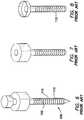
- FIG. 6illustrates a perspective view of a prior art assembled threaded trocar and obturator
- FIG. 7illustrates a perspective view of a prior art threaded cannula and housing
- FIG. 8illustrates a perspective view of a prior art threaded cannula
- FIG. 9illustrates a perspective view of a prior art cannula having an uninflated balloon at the distal end
- FIG. 10illustrates a perspective view of a prior art cannula having an inflated balloon at the distal end
- FIG. 11illustrates a prior art trocar-cannula having a distal retention balloon placed through a body wall in a first position
- FIG. 12illustrates a prior art trocar-cannula having a distal retention balloon placed through a body wall in a second position
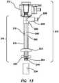
- FIG. 13illustrates a perspective view of an embodiment of trocar cannula assembly
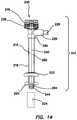
- FIG. 14illustrates a perspective view of an embodiment of sleeve subassembly of the trocar cannula assembly of FIG. 13 ;
- FIG. 15illustrates a perspective view of an embodiment of cannula of the trocar cannula assembly of FIG. 13 ;
- FIG. 16illustrates a detail cut away view of a distal end of the cannula of FIG. 15 ;
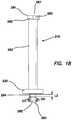
- FIG. 17illustrates a perspective view of an embodiment of sleeve of the trocar cannula assembly of FIG. 13 as manufactured by a stretch blow molding process
- FIG. 18illustrates a perspective view of the sleeve of FIG. 17 in an installation configuration
- FIG. 19illustrates a partial cross-sectional view of the distal end of the trocar cannula assembly of FIG. 13 ;
- FIG. 20illustrates a detail cut away view of the trocar cannula assembly of FIG. 13 ;
- FIG. 21illustrates a perspective view of a retention disk of the trocar cannula assembly of FIG. 13 ;
- FIG. 22illustrates a cross-sectional view of the retention disk of FIG. 21 ;
- FIG. 23illustrates a perspective view of a sleeve protector of the trocar cannula assembly of FIG. 13 ;
- FIG. 24illustrates a partial cross-sectional view of the distal end of the trocar cannula assembly of FIG. 13 ;
- FIG. 25illustrates an embodiment of a method for manufacturing a trocar cannula assembly
- FIG. 26illustrates another embodiment of a method for manufacturing a trocar cannula assembly
- FIG. 27illustrates another embodiment of a method for manufacturing a trocar cannula assembly
- FIG. 28illustrates another embodiment of a method for manufacturing a trocar cannula assembly
- FIG. 29illustrates another embodiment of a method for manufacturing a trocar cannula assembly
- FIG. 30illustrates a partial cross-sectional view of an embodiment of trocar cannula assembly in a partially-assembled configuration
- FIG. 31schematically illustrates a distal end of an embodiment of trocar cannula assembly in a partially-assembled configuration
- FIG. 32schematically illustrates a distal end of an embodiment of trocar cannula assembly in a partially-assembled configuration with a balloon in a deflated state
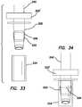
- FIG. 33schematically illustrates a distal end of an embodiment of trocar cannula assembly in a partially-assembled configuration with a balloon in a deflated state
- FIG. 34schematically illustrates a distal end of an embodiment of trocar cannula assembly in a partially-assembled configuration with a balloon in a deflated state and a sleeve protector advanced over the balloon;
- FIG. 35schematically illustrates a distal end of an embodiment of trocar cannula assembly in a partially-assembled configuration undergoing a sterilization process
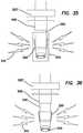
- FIG. 36schematically illustrates a distal end of an embodiment of trocar cannula assembly in a partially-assembled configuration with a balloon in a folded insertion configuration
- FIG. 37schematically illustrates a distal end of an embodiment of trocar cannula assembly in a partially-assembled configuration with a pre-creased balloon
- FIG. 38illustrates an exemplary graph of an insertion force in pounds versus elapsed time for a trocar cannula having a non-folded balloon
- FIG. 39illustrates an exemplary graph of an insertion force in pounds versus elapsed time for a trocar cannula having a proximally-folded balloon.
- a typical laparoscopic procedureis illustrated where a plurality of trocars 100 are placed through a body wall 50 , such as an abdominal wall, and into a body cavity 52 , such as an abdominal cavity.
- the body cavity 52is insufflated, or inflated with gas, to distend the body wall 50 and provide a working space for the laparoscopic procedure.
- the trocars 100each include a cannula 110 and a seal 150 . Positive pressure is maintained within the body cavity 52 by the seal 150 associated with the cannula 110 .
- the cannula 110must form a gas-tight seal against adjacent tissue. If positive pressure is lost, either through the seal 150 associated with the cannula 110 or the seal between the cannula and the adjacent tissue, the procedure may be compromised.
- the body wall 50may be greatly distended.
- the access sitesmay tend to enlarge under the distention of the body wall 50 and compromise the positioning and sealing of the cannula 110 .
- the manipulation of instruments 190 used through the trocars 100may result in movement of the cannulae 110 in either a proximal or distal direction within the access site through the body wall 50 . As this occurs, some liquefaction may take place and the preferred relationship between the cannula 110 and the body tissue may be compromised.
- a typical assembled trocar 100is shown having a cannula 110 , a seal housing 150 and an obturator 160 .
- the cannula 110typically has a smooth exterior surface 102 so that it may be inserted through the body wall 50 easily.
- the seal housing 150contains a seal system that prevents retrograde gas-flow.
- the obturator 160is a cutting or piercing instrument that creates the pathway through the body wall 50 through which the cannula 110 follows. Surgical obturators 160 are generally sized and configured to create a defect in tissue that is appropriate for the associated cannula 110 .
- the defectmay have a tendency to enlarge during a surgical procedure as the trocar 100 or cannula 110 is manipulated.
- the cannula 110may move or even be inadvertently withdrawn due to the friction between the instrument 190 and the seal 150 of the trocar housing.
- a trocar 100 or access devicewhere the outer surface 102 of the cannula 110 includes a plurality of raised features 115 .
- These raised features 115are sized and configured to increase resistance to proximal and distal motion as instruments 190 are maneuvered, and especially as specimens are removed, through the trocar 100 .
- the prior artincludes either sequential raised rings or a raised coarse-thread 115 . While the rings or threads 115 of the prior art may stabilize the cannula 110 to some degree, they do not necessarily seal the cannula 110 against the adjacent tissue of a body wall 50 . There may be gas loss associated with the use of these systems.
- the raised rings or threads 115also increase the insertion force required to penetrate a body wall 50 .
- the insertion forcemay be reduced in the instance of a continuous coarse thread 115 in comparison to a sequence of discrete raised rings or features as a threaded cannula 110 may actually be “screwed” into the tissue defect in accordance with the thread direction and pitch, rather than pushed through without appropriate rotation.
- a surgical access device 100includes a cannula 110 having an inflatable balloon 120 associated with the distal-end portion 122 of the cannula.
- the balloon 120is sized and configured to fit snugly around the cannula 110 in the uninflated condition.
- the balloon 120is inflated after the cannula 110 is properly placed through the body wall 50 and into the body cavity 52 .
- the balloon 120is generally held against the interior surface 54 of the body wall 50 by a counter-force that is associated with a sliding counter-force member, such as a foam bolster 180 .
- the bolster 180is associated with the proximal portion of the cannula 110 .
- the balloons 120 associated with the devices of the prior artare typically “thick-walled” structures constructed as part of the cannula 110 .
- the balloon 120is generally bonded to the distal-end portion 122 of the cannula 110 and an inflation channel or lumen is provided within the wall of the cannula 110 .
- the trocar cannula assembly 210can include a seal housing 212 and a sleeve sub assembly 214 comprising a trocar cannula 216 , a sleeve 218 including an inflatable balloon 220 , a retention disc 222 , and a tip protector 224 or sleeve protector.
- the seal housing 212 or valve housingcan include an instrument seal and a zero seal.
- the valve housingcan be removably coupled to the cannula 216 and in one embodiment includes an inlet for supplying insufflation gas into a body cavity such as the abdominal cavity.
- the instrument seal and zero seal enclosed in the valve housingin various embodiments can be separate or monolithic seals.
- the zero seal and instrument sealcan seal an instrument path through the valve housing into a lumen 236 ( FIG. 14 ) of the cannula 216 .
- the trocar cannula 216can have a an instrument seal and a zero seal, separate or monolithic seals, positioned directly therein with no separate valve housing such that the trocar cannula with a sealed instrument channel path has a relatively short length from a proximal end to the distal end defining a low height profile.
- the trocar cannula assembly 210can be sized to receive surgical instruments such as laparoscopic surgical tools having standard sizes.
- the trocar assembly 210can be a “5 mm trocar cannula,” sized and configured to receive surgical tools from sized up to a 5 mm surgical tool product class.
- a trocar assembly 210can be an “11 mm trocar cannula” or a “12 mm trocar cannula,” sized and configured to receive surgical tools sized as large as an 11 mm or 12 mm surgical tool product class respectively.
- the trocar cannula assembly 210can be included in a kit comprising the trocar cannula assembly 210 , a seal housing 212 and an obturator insertable through the seal housing 212 and the cannula assembly 210 .
- the trocar cannula 216can include a fluid inlet port 226 .
- the fluid inlet port 226is adapted to receive a source of fluid such as a syringe.
- the fluidcan comprise air, another gas such as carbon dioxide, a gas mixture, or a liquid such as water, a saline solution, or another liquid solution.
- the fluid inlet port 226is fluidly coupled to the sleeve 218 such that addition of fluid to the fluid inlet port 226 inflates the balloon 220 .
- the fluid inlet port 226can include a one-way valve such as a poppet valve or check valve 228 .
- a one-way valvesuch as a poppet valve or check valve 228 .
- the check valve 228maintains the fluid within the sleeve 218 and balloon 220 of the trocar cannula assembly 210 .
- the check valve 228can be selectively opened to allow the fluid to escape or be withdrawn such as by syringe when it is desired to deflate the balloon 220 .
- the trocar cannula 216has a proximal end 230 , a distal end 232 , and a lumen 236 extending from the proximal end 230 to the distal end 232 along a longitudinal axis L.
- the lumen 236is configured to receive a surgical instrument therein such as a laparoscopic surgical tool.
- the trocar cannula 216comprises a seal housing interface 238 at the proximal end 230 , the fluid inlet port 226 distal the seal housing interface 238 , a generally tubular cannula body 240 extending distally from the fluid inlet port 226 , an annular recess such as an annular groove 242 in the cannula body 240 adjacent the distal end 232 of the cannula 216 , and a distal tip 244 .
- the seal housing interface 238can comprise a seal such as an O-ring 246 ( FIG. 14 ) to sealingly engage a seal housing.
- the fluid inlet port 226comprises a fluid inlet 250 and a fluid dome 252 .
- the fluid inlet 250is configured to receive the source of inflation fluid and can include the check valve 228 positioned therein ( FIG. 14 ).
- the fluid dome 252 of the fluid inlet port 226is fluidly coupled to the fluid inlet 250 .
- the fluid inlet port 226can have a generally smooth outer surface 254 .
- the smooth outer surface 254can allow adhesive to flow underneath the sleeve 218 and obtain a relatively strong balloon-to-cannula bond.
- the fluid inlet port 226can be shaped with a curved profile such as a generally teardrop shape and the fluid dome 252 can have a curved profile to reduce the likelihood of the fluid pathway for balloon inflation/deflation can become plugged.
- the fluid inlet port 226can have another curved profile such as a generally cylindrical, elliptical, or oval profile.
- the fluid inlet port 226can have another curvilinear profile.
- the cannula body 240extends distally from the fluid inlet port 226 to the distal end 232 of the cannula 216 .
- the cannula body 240has an exterior surface 260 and a first outer diameter D 1 .
- the exterior surface 260 of the cannula body 40can be configured to facilitate installation of the sleeve 218 thereon.
- the exterior surface 260 of the cannula body 240can include a relatively lightly textured surface finish to facilitate sliding advancement of the sleeve 218 over the cannula body 240 .
- the cannula body 240can include one or more fluid channels 262 or grooves that extend generally longitudinally from the fluid inlet port 226 towards the distal end 232 of the cannula 216 .
- the fluid channel 262can be formed in the exterior surface 260 of the cannula body 240 and extend a depth d into the cannula body 240 .
- the fluid channel 262is fluidly coupled to the fluid inlet port 226 and extends distally to a location adjacent the balloon 220 of the sleeve 218 . ( FIG. 14 ).
- the fluid channel 262can thus work in conjunction with the balloon 220 to allow fluid passage for balloon 220 inflation and deflation.
- the sleeve sub-assembly 214can have a relatively small outer diameter and low-profile.
- the cannula assembly 210can have a relatively low insertion force.
- the balloon 220 and fluid channel 262 geometrycan reduce the incidence of the balloon 220 plugging the fluid flow path during deflation.
- the cannula body 240can include an annular recess such as an annular groove 242 adjacent the distal end of the trocar cannula 216 .
- the annular groove 242is formed in the cannula body 240 at an orientation generally perpendicular to the longitudinal axis L of the trocar cannula 216 . In other embodiments, other orientations of the annular groove 242 can be formed.
- the annular recesscomprises an annular groove 242 having a recessed surface extending a relatively short length along the longitudinal axis L of the trocar cannula 216 adjacent the distal end of the trocar cannula 216 .
- the annular recess or annular groovecan include a recessed surface extending from a location adjacent the distal end proximally to a location between the proximal end or the distal end of the trocar cannula 216 or to a location adjacent the proximal end of the trocar cannula 216 .
- FIG. 16illustrates a cut away detail view of an embodiment of annular groove 242 .
- the annular groove 242can have a proximal edge 270 , a distal edge 272 , and an annular interface surface 274 between the proximal edge 270 and the distal edge 272 .
- the annular interface surface 274can have a second outer diameter D 2 smaller than the first outer diameter D 1 of the cannula body 240 .
- the proximal edge 270can have a generally stepped edge extending between the first outer diameter D 1 of the cannula body 240 and the second outer diameter D 2 of the annular interface surface 274 .
- the stepped edgecan enhance sealing performance of the sleeve 218 to the cannula body 240 to maintain fluid within the balloon 220 in an inflated configuration.
- the distal edge 272 of the annular groove 242can have a ramped edge.
- the ramped edgecan extend at an angle transverse to the annular interface surface 274 .
- the distal edge 272 of the annular groove 242can comprise a generally stepped edge or an edge having another geometric profile such as a radiused curvilinear edge.
- the distal tip 244 at the distal end 232 of the cannula 216has a distal edge 278 that extends at an angle ⁇ relative to a plane perpendicular to the longitudinal axis L of the cannula 216 .
- the angle ⁇can be between about 5 degrees and about 45 degrees.
- the distal edge 278 of the distal tip 244can be angled at approximately 17 degrees relative to the plane perpendicular to the longitudinal axis L.
- the anglecan be slightly different to match the correlated cannulae 216 .
- the angle ⁇can be approximately 20 degrees
- the angle ⁇can be approximately 12 degrees.
- other anglescan be used.
- the angled distal tip 244can greatly reduce the force required to insert the cannula assembly 210 through a body wall such as the patient's abdominal wall as compared with a distal tip having a straight tip with a distal edge perpendicular to the longitudinal axis of the cannula.
- Balloon trocars having straight tipshave primarily been introduced through body walls into surgical sites through relatively large incisions using a cut-down technique.
- the angled distal tip 244can facilitate the use of a fixation cannula in surgical procedures including various cannula insertion techniques with various incision lengths.
- a fixation trocar having an angled distal tipcan be inserted with a relatively low insertion force with insertion techniques including insertion techniques with bladed, non-bladed optical, or insufflation obturators.
- the cannula body 240can be formed of a polycarbonate material. Desirably, the hardness and relative rigidity of the material allows the cannula 216 to serve as a supporting tube to install the flexible sleeve 218 and balloon 220 and a port to insert obturators or other medical instruments. In other embodiments, the cannula body 240 can comprise other materials.
- a sleeveextends from adjacent the proximal end of the trocar cannula to adjacent the distal end of the trocar cannula.
- the sleevehas a proximal end and a distal end with an inflatable segment adjacent the distal end.
- the sleevecan be coupled to the trocar cannula at the proximal end of the sleeve and the distal end of the sleeve.
- the sleevecan be coupled to the trocar cannula by a technique that creates a relatively low diametric profile at the coupling, has desirable sealing performance, and can be efficiently manufactured.
- the trocar cannulacan have a substantially smooth continuous outer surface, and the sleeve can be coupled to the smooth surface by application of an adhesive to form a chemical bond.
- the sleevecan be coupled to the trocar cannula by heat welding or UV welding to create a fused coupled region. In some embodiments, as further discussed with respect to FIGS.
- the sleevecan be coupled to the trocar cannula at a non-continuous region of the outer surface, such as, for example one or more annular grooves formed therein.
- different coupling techniquescan be used at the proximal end of the sleeve than are used at the distal end, while in other embodiments, substantially similar coupling techniques can be used at the proximal end and the distal end of the sleeve.
- the sleeve 218for the cannula assembly 210 is illustrated.
- the sleeve 218comprises a proximal interface section 280 or coupler at the proximal end 281 , an elongate tubular body 282 extending distally from the coupler, a balloon 220 positioned distal the elongate tubular body 282 , and an annular ring 284 distal the balloon.
- the sleeve 218can be monolithically unitarily formed, such as by stretch blow molding.
- the stretch-blow molding processallows for a high degree of control of the balloon material, thickness and shape.
- the sleeve 218can comprise a polyolefin material such as one commonly used as heat shrink tubing.
- a Sumitomo A2 clear polyolefin tubingcan be used.
- a sleeve 218 comprising a polyolefin materialis latex free, non-porous, and non-fragmenting, unlike latex or silicone rubber materials.
- the polyolefin tubing materialcan be soft, flexible, and can include a high degree of cross-linking such that it has a relatively high strength for a given material thickness compared to other tested materials.
- the balloon 220can typically be over-inflated with an average of 5 times of a designed inflation pressure without rupturing. Also, the softness and flexibility of the polyolefin material improves the feel of the device for the user while also reducing the insertion force.
- the sleevecan comprise other materials such as a silicone material, cilran, polyisoprene, a polyurethane material, a polyurethane blend, TYGON®, VITON®, SANTOPRENE®, MYLAR®, or another suitable polymeric material.
- the cannula assemblyincludes one balloon 220 positioned at a distal location on the cannula 216 . It is contemplated that in various other embodiments, additional balloons can be incorporated to account for variations in a patient's abdominal wall thickness and anatomy. Also, balloons at different locations may use different material. The balloon may be distensible or non-distensible or a combination of both.
- the balloon 220in one embodiment is doughnut shaped or in one aspect disc-like. The size and/or location of the balloon 220 can vary to vary the desired retention of the trocar cannula 216 with the patient's body.
- the coupler 280is sized and configured to engage the cannula 216 .
- the coupler 280has a curved profile in an eccentric or generally teardrop shape to match the teardrop shape of the fluid dome 252 of the cannula 216 .
- this matching profilecan allow a tight fit when the sleeve 218 is installed on to the cannula 216 , reducing the potential for leakage therebetween.
- an outer surface 286 of the coupler at the proximal end 281is textured.
- the rough surfacefacilitates the bonding of adhesives to the sleeve 218 , preventing the sleeve 218 from being separated from the cannula 216 when the balloon 220 is fully inflated.
- a roughened or textured surfacecan create a plurality of relatively small channels which enhance flow of a chemical adhesive though a wicking or capillary action process to create a strong adhesive bond between the sleeve 218 and the cannula 216 .
- a textured or roughened surface at the couplercan allow the sleeve 218 to comprise a material that can be otherwise difficult to bond with adhesives.
- the elongate tubular body 282 or shaft of the sleeve 218extends distally from the coupler 280 .
- the shaftis uniform and thin-walled, but thick enough to withstand sliding movement of a retention disc 222 or other bolster.
- FIG. 19illustrates a distal end of the cannula assembly 210 with the sleeve 218 positioned on the cannula 216 .
- a sleeve 218 formed by a stretch blow molding processcan allow for increased control of the thickness t 1 of the elongate tubular body 282 to minimize an outer diameter of the trocar cannula assembly 210 resulting in a smaller incision size for the patient.
- the elongate tubular body 282can have a thickness t 1 of approximately 0.008 inches to approximately 0.012 inches.
- the sleeve 218comprises a non-distensible inflatable balloon 220 distal of the elongate tubular body 282 .
- the balloon 220can have a thickness t 2 that is smaller than the thickness t 1 of the elongate tubular body 282 .
- stretch blow molding a polyolefin material to form the balloon 220can provide a high strength material with a relatively low thickness.
- the ballooncan have a thickness between about 0.0005 inches and 0.002 inches. In certain embodiments, the balloon can have a thickness of approximately 0.001 inch.
- abrupt thickness transitions at the balloon/shaft interfacescan be significantly reduced or eliminated through the stretch blow molding process.
- the relatively high degree of control in the balloon thickness of the stretch blow molding processcan also contribute to a minimized outer diameter adjacent the distal end of the cannula assembly, resulting in a reduction in insertion force.
- the sleeve 218further comprises an annular ring 284 distal the balloon 220 .
- the annular ring 284has an outer diameter DO, an inner diameter D 3 in an undisturbed state, a thickness t 3 between the inner diameter D 3 and the outer diameter DO, and a length 12 .
- the annular ring 284can comprise a segment of material having an outer diameter DO smaller than an outer diameter of the elongate tubular body 282 .
- the thickness t 3 of the annular ring 284is greater than the thickness t 1 of the elongate tubular body 282 . Accordingly, the annular ring 284 is relatively rigid compared with the elongate tubular body 282 .
- the inner diameter D 3 of the annular ring 284 in the undisturbed stateis smaller than the outer diameter D 2 of the annular groove 242 .
- a ratio of the inner diameter D 3 of the annular ring 284 in the undisturbed state to the outer diameter D 2 of the annular groove 242can be between approximately 75:100 and approximately 85:100.
- this undersized relationship of the annular ring 284 relative to the annular groove 242provides a snap-ring design having an interference fit that can assist in attachment of the sleeve 218 to the cannula 216 .
- different undersized ratioscan be used.
- inner diameter D 3 of the annular ring 284 in the undisturbed statecan be approximately 0.24 inches and the outer diameter D 2 of the annular groove 242 can be approximately 0.32 inches, resulting in an undersized ratio of approximately 76:100.
- inner diameter D 3 of the annular ring 284 in the undisturbed statecan be approximately 0.42 inches and the outer diameter D 2 of the annular groove 242 can be approximately 0.5 inches, resulting in an undersized ratio of approximately 84:100.
- inner diameter D 3 of the annular ring 284 in the undisturbed statecan be approximately 0.49 inches and the outer diameter D 2 of the annular groove 242 can be approximately 0.57 inches, resulting in an undersized ratio of approximately 85:100. In other embodiments, it is contemplated that other undersized ratios can be used.
- As the sleeve 218 is installed on the cannula 216its undersized annular ring 284 tightly fits in the annular groove 242 of the cannula 216 . The interference fit of these two components maximizes a sealing effect, preventing air from leaking between the sleeve 218 and the cannula 216 .
- the snap-ring designreinforces a distal hoop strength of the cannula 216 after the balloon 220 is installed.
- the annular ring 284 and the annular groove 242are sized and configured such that the outer diameter DO of an outer surface 288 of the annular ring 284 is flush with or recessed from an outer surface of the distal tip 244 of the cannula.
- the snap fit ring designallows for a smooth transition from cannula distal tip 244 to balloon 220 , therefore reducing the insertion force.
- the annular groove 242can be positioned adjacent the distal end of the cannula body 240 such that the cannula 216 can have an optimized insertion force reduction without compromising a working distance of the cannula assembly 210 .
- FIG. 20illustrates a cut-away detail view of the distal end of the cannula assembly 210 with the sleeve 218 positioned on the cannula 216 .
- the outer surface 288 of the annular ring 284 at the distal end 283 of the sleeve 218is textured, providing a rough bonding surface to assist in the bonding of adhesives to the sleeve 218 by retaining adhesive and to promote flow of the adhesives between the sleeve and the cannula by wicking of adhesive through a capillary action process.
- a combination of cyanoacrylate instant adhesive and UV cure adhesivecan be used for the sleeve-cannula bond coupling the annular ring 218 to the annular groove 242 .
- other adhesivessuch as only a cyanoacrylate adhesive or only a UV cure adhesive, or another type of adhesive can be used.
- the adhesivecan be applied substantially within the annular groove 242 such that the distal end 232 of the cannula 216 can have a smooth low profile transition between the sleeve 218 and the cannula 216 .
- the low profile transition between the sleeve 218 and the cannula 216can reduce the insertion force required to position the cannula assembly 210 in a surgical site.
- the low profile transitioncan be further enhanced by disposition of an adhesive 290 predominantly within the annular groove 242 of the cannula body 240 .
- the annular ring 284 of the sleeve 218 and the annular groove 242 of the cannula 216can be sized and configured to facilitate the disposition of the adhesive 290 predominantly within the annular groove 242 .
- the annular surface of the annular groovehas a first length 11 along the longitudinal axis of the cannula, the annular ring has a second length 12 along the longitudinal axis of the cannula, and the second length is smaller than the first length.
- the annular interface surface 274 of the annular groove 242can comprise an engagement segment 291 and an exposed segment 293 .
- the engagement segment 291can be defined by the second length 12 and engaged by the annular ring 284 .
- the exposed segment 293can be defined by a difference between the first length 11 and the second length 12 .
- the exposed segment 293can desirably be sized to provide a sufficient surface for disposition of a bead of adhesive to maintain the annular ring 284 of the sleeve 218 with respect to the annular groove 242 .
- an adhesive 290can be at least partially applied to the exposed segment 293 of the annular interface surface 274 to couple the annular ring 284 to the annular groove 242 .
- the sleeve 218can be adhesively bonded to the cannula 216 at the proximal interface surface 280 or coupler with a combination of cyanoacrylate instant adhesive and UV cure adhesive similar to the adhesive bonding of the annular ring 284 to the annular groove 242 .
- other adhesivessuch as only a cyanoacrylate adhesive or only a UV cure adhesive, or another type of adhesive can be used.
- FIGS. 21 and 22illustrate a retention disc 222 for positioning on the cannula assembly 210 .
- the cannula assembly 210includes a proximal fixation member such as a retention disc 222 positioned proximal the balloon 220 around the elongate tubular body 282 of the sleeve 218 .
- the balloon 220can be inflated to maintain the position of the trocar cannula assembly 210 in the surgical site, and the proximal fixation member or retention disc 222 can prevent the trocar cannula 216 from advancing further into the surgical site.
- the retention disc 222can comprise a generally circular disc with a center hole 292 defining a passage 294 through the retention disc 222 .
- the passage 294 of the center hole 292can have a ribbed profile on an inner diameter.
- the ribbed profilecan include a plurality of annular grooves 296 .
- the ribbed profilecan frictionally engage an outer surface of the elongate tubular body 282 of the sleeve 218 such that the retention disc 222 is manually slidable along the sleeve 218 but tends to remain in a selected position.
- the retention disc 222can be formed of an elastomeric polymer material such as a KRATON® material.
- a retention disc 222 formed of a KRATON® materialcan provide a desired level of frictional engagement with the outer surface of the sleeve 218 and present an ergonomically pleasing soft, flexible feel to a user of the trocar cannula.
- the round corners and soft material of the retention disc 222provide an atraumatic means to hold the trocar in place.
- the retention disc 222can be formed by an injection molding process.
- embodiments of a trocar cannula having a single molded retention disc 222can have manufacturing and assembly efficiencies and facilitate ease of use relative to a clamp mechanism having multiple assembled components.
- the trocar cannula assembly 210can be configured to resist movement of the retention disc 222 proximally along the cannula body 240 to prevent the trocar cannula 216 from advancing further into the surgical site.
- an exterior surface 260 of the cannula body 240can have a slight taper such that it has a smaller outer diameter at the distal end relative to the outer diameter at the proximal end of the cannula body.
- a friction force generated by the frictional engagement between the retention disc 222 and the sleeve 218can increase as the retention disc 222 is slid proximally along the trocar cannula 216 .
- the retention disc 222can be used to fixate the trocar cannula 216 relative to a body wall.
- the tight fit, ribbed profile, and tapered cannula 216prevent the retention disc 222 from advancing along the cannula body 240 when an instrument is inserted into the cannula 216 .
- a retention disc 222comprising an elastomeric polymer material can exhibit creep when stored under tension.
- the exterior surface 260 of the cannula body 240includes a slight taper, before use the retention disc 222 can be positioned adjacent the distal end having a relatively small outer diameter when not in use to reduce the incidence of creep in the retention disc 222 .
- the retention disk 222is advanced proximally up the shaft of the cannula 216 to an area of larger cannula diameter, allowing placement and fixation of the disc 222 .
- such a tapered cannula body 240can have further advantages in manufacturability of the cannula body 240 .
- such a tapered profilecan facilitate release of the cannula body 240 from a mold in embodiments where the cannula body 240 is formed with an injection molding process.
- the cannula assembly 210can comprise a bolster 222 ′ (See, e.g., FIGS. 31-36 ) such as a generally cylindrical or conical stability member with a clamp mechanism.
- the cannula assembly 210can include a stability assembly including one of the various clamp mechanisms described in U.S. Pat. No. 8,162,893, to Okihisa et al., entitled “TROCAR STABILITY ASSEMBLY,” which is incorporated herein by reference in its entirety.
- a trocar assembly 210can include a sleeve protector 224 to maintain a position of the balloon 220 relative to the body 240 and to protect the balloon 220 during shipping. Moreover, the required insertion force can be observed to vary proportionally with an overall outer diameter of the trocar cannula assembly 210 at the balloon 220 . Thus, before use, it can be desirable to reduce insertion force by folding the balloon 220 into an insertion configuration having a relatively smooth transition from the distal tip 244 of the cannula 216 to the balloon 222 .
- a non-elastic or non-distensible balloon 220 in a deflated or insertion configurationdoes not automatically conform to the exterior surface 260 of the cannula body 240 .
- the materialcan have a tendency to wrinkle, form folds and/or creases and may project at various points away from the exterior surface 260 of the cannula body 240 .
- the irregularities that the un-inflated balloon may possess,can present resistance during insertion of the un-inflated retention balloon 220 through a body wall. Folding the balloon 220 into the insertion condition can reduce the force required for insertion.
- the balloon 220in the insertion configuration is folded along the cannula body 240 towards the proximal end 230 of the cannula 216 . Folding the balloon 220 towards the proximal end 230 can result in one or more folds in the balloon 220 in the insertion configuration.
- the balloon 220can be folded proximally in a single step and in other embodiments, the balloon 220 can be initially folded distally in a first fold and subsequently folded proximally in a second fold. By folding the balloon 220 against the trocar placement direction, it helps reduce the insertion force and lower the balloon diametric profile.
- the sleeve protector 224can maintain the balloon 220 in the insertion configuration until it is removed from the trocar cannula assembly 210 for insertion to a surgical site. Moreover, the sleeve protector 224 can protect the balloon 220 and/or distal tip 244 of the cannula assembly 210 from damage during shipping or prior to operational use.
- FIG. 23illustrates a sleeve protector 224 comprising a hollow tubular segment.
- the sleeve protector 224can be configured to provide a relatively small area of surface contact with the balloon 220 of the sleeve 218 .
- the sleeve protector 224can comprise an inner surface 300 having a plurality of radially inwardly projecting ribs 302 extending generally longitudinally. With the sleeve protector 224 positioned on the trocar assembly 210 , the ribs 302 can contact an outer surface of the balloon 220 in the insertion configuration. Desirably, the relatively small amount of surface contact between the ribs 302 and the balloon 220 can reduce the incidence of wear on the balloon 220 from the sleeve protector 224 .
- the ribs 302can be configured to reduce the insertion force of the trocar cannula assembly 210 .
- the ribs 302are radiused, which can facilitate installation and removal of the sleeve protector 224 and can further reduce wear on the balloon 220 .
- the sleeve protector 224is configured to prevent proximal movement of the sleeve protector 224 past the balloon 220 .
- the sleeve protector 224is shaped to have a somewhat smaller diameter at a distal end than at a proximal end to prevent the sleeve protector 224 from moving proximally and past the balloon 220 to maintain the sleeve protector 224 on the balloon 220 .
- the sleeve protector 224may have detents or projections that prevent the sleeve protector 224 from moving proximally.
- the cannula assembly 210can further comprise a spacer between the retention disk 222 or bolster 222 ′ and the sleeve protector 224 to prevent the sleeve protector 224 from moving proximally past the balloon 220 .
- the retention disk 222 or bolster 222 ′in one embodiment is positioned near the balloon 220 or the sleeve protector 224 is sufficiently long to contact the retention disk 222 or bolster 222 ′ to prevent the sleeve protector 224 from moving proximally past the balloon 220 . Preventing the sleeve protector 224 from moving proximally past the balloon 220 prevents the sleeve protector 224 from losing contact with the balloon 220 losing pressure and protection of the balloon 220 and tip 244 .
- the sleeve protector 224is incorporated into or attached to the retention disk 222 or bolster 222 ′. As such, the sleeve protector 224 attached to the bolster 222 ′ can maintain the balloon 220 in the folded position. During operation, the retention disk 222 or bolster 222 ′ is moved proximally and along with it the sleeve protector 224 to expose the balloon 220 . In one embodiment, the sleeve protector 224 is removably attached to the retention disk 222 or bolster 222 ′ and thus moved distally to expose the balloon 220 and remove the sleeve protector 224 from the bolster 222 ′.
- FIGS. 25-29illustrate various embodiments of methods for manufacture of trocars described herein.
- Embodiments of cannula assembly 210 discussed hereincan include a preformed sleeve 218 .
- the cannula 216can be formed from a suitable material, such as a polycarbonate material, with an injection molding process.
- the sleeve 218can be formed apart from the cannula 216 with a stretch blow-mold process and subsequently assembled to the cannula 216 .
- a method of making a cannula assembly 210is illustrated.
- a roll of polyolefin heat-shrink tubingis cut into sections or blanks then heated to shrink the tubing down.
- Each section or blank of tubingis then heated, stretched and inflated into a conditioning mold having a desired geometry to stretch-blow-mold 402 and pre-form the sleeve.
- the preformed sleeve 218can include a proximal end 281 , a distal end 283 , a proximal interface section 280 , an elongate tubular body 282 , a balloon 220 distal the tubular body 282 , and an annular ring 284 distal the balloon 220 as discussed herein with respect to various embodiments of cannula assembly 210 .
- the sleeve 218can be stretch blow molded to a slightly oversized profile relative to the exterior surface 260 of the cannula body 240 to facilitate installation of the sleeve 218 on the cannula 216 .
- the sleeve 218can be heated 416 to shrink onto the exterior surface 260 of the cannula body 240 .
- the elongate tubular body 282 of the sleevecan be formed line-to-line for installation and then heated slightly to shrink down onto the exterior surface 260 of the cannula body 240 .
- the pre-formed sleeve 218can be trimmed on the proximal end 281 and a rough cut is made at the distal end 283 to form or create 404 a distal installation cup 285 , as shown in FIGS. 17 and 18 .
- An inner surface 287 of the sleeve 218can generally match an exterior surface 260 of the cannula body 240 , making it easy to slide over the cannula 216 and install the balloon 220 .
- the distal installation cup 285is trimmed 414 and removed.
- the distal installation cup 285can provide a surface for distal balloon installation equipment to manipulate the sleeve 218 and advance the sleeve 218 relative to the cannula 216 .
- this distal installation cup 285provides a sacrificial portion of the distal end 283 that allows installation while protecting the snap-ring features of the annular ring 284 from damage.
- the balloon 220 of the sleeve 218can be molded in one shape or width, but installed and attached in a different shape and width.
- the pre-formed balloon 220is blow-molded or formed 406 with a circular disc shaped balloon, as shown in FIGS. 17-18 .
- the distal end 283 of the sleeve 218is advanced 408 towards the proximal end 281 of the sleeve 218 to reconfigure the balloon 220 of the sleeve 218 into a generally toroidal or donut shaped balloon as shown in FIG. 19 .
- the preformed sleeve 218can include a balloon 220 having other geometries, such as a generally frusto-conical profile or another rounded profile.
- this control in balloon shapecan maximize the total working distance of the device.
- the round balloon shape and soft materialprovides an atraumatic means to hold the trocar assembly 210 in place.
- the preformed sleeve 218can be advanced 410 over the cannula 216 .
- the sleeve 218can be advanced until the proximal interface section 280 of the sleeve 218 is positioned about a fluid inlet port 226 of the cannula 216 and the annular ring 284 of the sleeve 218 is positioned 412 in the annular groove 242 .
- the stretch blow molding process for the sleeve 218results in the potential for faster processing, more consistent manufacturing and increased ability to design, shape and form the sleeve 218 as compared with a process including forming a balloon 220 on the cannula 216 .
- the stretch blow molding processcan be used to preform a sleeve 218 having relatively thin-walled sections as discussed above with respect to various embodiments of cannula assembly 210 .
- the use of the pre-formed sleeve 218simplifies the manufacturing process of the sleeve sub assembly 214 . Stretch blow molding the sleeve 218 can allow for a high degree of control of the sleeve 218 profile.
- the pre-formed sleeve 218can have a profile, such as with a proximal interface section 280 and an annular ring 284 with an interference fit relative to an annular groove 242 of the cannula 216 to facilitate sealing engagement to the cannula 216 by adhesive bonding without distal and proximal thread windings.
- the use of a pre-formed sleeve 218can therefore increase manufacturing efficiencies while reducing insertion force requirements for the resulting cannula assembly 210 .
- the sleeve 218can be coupled to the cannula 216 .
- the proximal end 281 of the sleeve 218 and the distal end 283 of the sleeve 218are each bonded 418 to the cannula 216 .
- the proximal interface section 280 of the sleeve 218is adhered 420 to a location adjacent the proximal end 230 of the cannula 216 and the annular ring 284 is adhered 422 to the annular groove 242 .
- a cyanoacrylate adhesive and a UV cure bonding adhesivecan be used to couple the sleeve 218 to the cannula 216 .
- the retention disc 222can be positioned 424 proximally of the balloon 220 around an outer surface of the sleeve 218 .
- a fixturecan be used to slightly expand the disc 222 to install over the balloon 220 and to avoid any possible balloon 220 damage.
- the balloon 220can be folded 426 along the elongate tubular body 282 of the sleeve 218 towards the proximal end 230 of the cannula 216 into an insertion configuration.
- the sleeve protector 224can then be positioned 428 over the balloon 220 to keep the balloon 220 folded until use and to retain a smooth transition from cannula distal tip 244 to balloon 220 .
- the retention disc 222is placed relatively close to the distal end 232 of the cannula 216 with the sleeve protector 224 flushed against it.
- the retention disc 222acts as an anchor and prevents the sleeve protector 224 from sliding proximally past the balloon 220 prior to use.
- the retention disc 222can be placed at a relatively small diameter of the cannula body 240 to avoid stretching the inner diameter prior to use.
- the relatively low diametric profile of the folded balloon 220can be enhanced by evacuating air from the balloon 220 during folding and sterilizing the balloon 220 after positioning the sleeve protector 224 .
- a balloon 220 attached to a cannula 216 of a trocar cannula assembly 210is connected to a syringe, vacuum or the like and air within the balloon 220 is removed.
- the deflated balloon 220is folded back towards the proximal end 230 of the cannula 216 . The folding and/or the removal or lack of air in the balloon 220 is maintained.
- Sterilization of the balloon 220 and/or trocar cannula assembly 210may occur. Prior to operational use or insertion of the balloon 220 and/or cannula 216 into a body cavity, the balloon 220 is allowed to unfold and air introduced into the balloon 220 . In one embodiment, maintenance of the fold is removed and/or absence of or prevention of the removal of air is discontinued.
- the trocar cannula assembly 210initially is inflated or partially filled with air. This inflation can occur as the balloon 220 is attached to the cannula 216 .
- the balloon 220is formed on a stretch blow molded sleeve 218 and thus in a neutral or initial state is in an extended or inflated condition. As such, as the sleeve 218 is attached to the cannula 216 , air is trapped or caught within the balloon 220 .
- aircan be extracted from the balloon 220 via the one or more fluid channels 262 of the cannula 216 connected to the check valve 228 and the balloon 220 , as illustrated schematically in FIG. 32 .
- Various balloon 220 folding techniquescan be used to provide a relatively low diametric profile to reduce insertion force for the trocar cannula assembly.
- the balloon 220can be folded proximally upon itself in a single folding step.
- the balloon 220can be pushed against or towards a retention disk 222 or bolster 222 ′ causing the balloon 220 to fold upon itself in a proximal direction.
- the balloon 220can be folded in a two-step process with an initial distal fold followed by a proximal fold.
- the balloon folding technique to be incorporated in a method of manufacture for a trocar cannula assemblycan be selected to provide a desired insertion force and ease of manufacturability.
- the retention disk 222 or bolster 222 ′ of the trocar without a sleeve or conecan be slid or pushed against a proximal end of the balloon 220 to push or apply a force distally away from the proximal end 230 of the trocar cannula 216 .
- the distal end 306 of the bolstercan be positioned adjacent the proximal end 308 of the balloon 220 , as illustrated schematically in FIG. 33 .
- a trocar tip sleeve protector 224Using a trocar tip sleeve protector 224 , the balloon 220 is pushed against or towards the retention disk 222 or bolster 222 ′ causing the balloon 220 to fold upon itself in a proximal direction. A compressive force of the trocar tip sleeve protector 224 against the balloon 220 continues as the trocar tip sleeve protector 224 slides over the balloon 220 . This sliding movement fully compresses the balloon 220 into a preferred, compressed condition, as illustrated schematically in FIGS. 33 and 34 .
- the sleeve protector 224can be advanced using a linear motion or a slight twisting motion to provide a relatively low balloon insertion profile.
- the retention disk 222 or bolstercan be moved proximally when the sleeve protector 224 is in place covering the entire folded balloon 222 . Placement of the tip sleeve protector 224 over the balloon 220 and in particular over the fold in the balloon 220 maintains the fold in the balloon 220 and/or the evacuation of air from the balloon 220 .
- a removable base supportis removably attached to the cannula 216 and used as a support to push the proximal end of the balloon 220 .
- subjecting or applying sterilization 310 to the balloon 220e.g., applying gamma sterilization to the balloon 220 further maintains the balloon 220 folded against the cannula 216 and further reduces the outer profile of the balloon 220 to be flushed or flattened against or towards the outer surface of the cannula 216 .
- the resulting inflation configuration of the balloon 220is illustrated schematically in FIG. 36 .
- the sterilization 310 processin certain embodiments may include electron-beam, gamma radiation or heat.
- the irradiationprovides a “setting” of the folded material to a predetermined condition, size and shape.
- the material of the compressed balloon 220may be partially cross-linked during this process.
- a heat-shrinkable materialmay be used for the sleeve 218 thereby compressing the balloon 220 without the friction associated with sliding a snug fitting sleeve protector 224 over the un-inflated balloon.
- the irradiation process 220in one embodiment, may involve a sterilization process in which the assembled trocar cannula 216 and sleeve 218 with balloon 220 are sterilized for surgical use.
- the balloon 220 in one embodimentcan be pre-creased 304 or scored or otherwise preconditioned to facilitate folding (and/or the direction of the fold) of the balloon 220 towards the proximal end 230 of the balloon trocar cannula 216 .
- the balloon 220 in one embodimentis dimensioned, shaped or made of different materials to facilitate folding of the balloon.
- attachment of the balloon 220 to the cannula 216is also positioned and specifically placed to facilitate folding of the balloon 220 .
- a proximal end of the balloon 220can be advanced towards a distal end of the balloon during positioning of the sleeve 218 on the cannula 216 to incline or bias a mid-point or center of the balloon 220 towards the proximal end of the balloon 220 .
- the balloon 220tends to fold towards the proximal end of the balloon and the trocar and away from the distal end.
- different portions of the balloon 220may be weakened or reinforced relative to other portions of the balloon 220 to bias or otherwise cause the balloon 220 to tend to fold proximally versus distally.
- a proximal portion of the balloon 220is weaker than the distal portion of the balloon 220 .
- a support structuresuch as internal balloons, membranes or scaffoldings within the balloon 220 causes the balloon 220 to tend to fold proximally.
- ramp-like folds on the proximal portion of the balloon 220can also reduce the insertion force of the trocar cannula assembly 210 by slightly angling the balloon 220 to provide a taper-like form.
- advancement of the sleeve protector 224 with radially inwardly projecting ribs 302 over the balloon 220can form ramp-like folds on the balloon 220 .
- sterilizationsuch as gamma sterilization, applied to the balloon 220 causes the folds of the balloon 220 to have pronounced ramp-like folds.
- ramp-like foldsunfold or smooth out such that the outer surface of the balloon 220 is smooth or free of projections or protrusions such that the inflated balloon 220 provides a flush arrangement of the proximal portion of the balloon 220 against the interior of the body wall to enhance the seal against the body wall.
- a trocar cannula assembly 210having a mechanically folded inflatable non-distensible member or balloon 220 sized and configured to exhibit a first, insertion profile, and when inflated exhibiting a second, retention profile.
- the first profileis provided by mechanically compressing the balloon 220 upon a tubular structure and supplying sterilization to set the balloon material in a low profile condition.
- a method for folding and holding an un-inflated non-elastic retention balloon 220 in a low-profile conditionis provided.
- the methodcomprises attaching the balloon 220 to an access channel or cannula 216 ; folding the un-inflated balloon 220 proximally; sliding a retention member such as retention disk 222 or bolster to occupy the folded-over, proximal portion of the un-inflated balloon 220 ; sliding a sleeve protector 224 over the folded, un-inflated balloon 220 ; sliding the retention disk or bolster proximally to allow the folded balloon 220 to conform to the surface of the cannula 216 ; and irradiating the assembly in a process of sterilization.
- a method for folding and holding an un-inflated non-elastic retention balloon 220 in a low-profile conditionis provided.
- the methodcomprises attaching said balloon 220 to an access channel or cannula 216 ; folding said un-inflated balloon 220 proximally; sliding a retention disk 222 or bolster 222 ′ to occupy the folded-over, proximal portion of the un-inflated balloon 220 ; sliding a sleeve protector 224 over the folded, un-inflated balloon; sliding the retention disk 222 or bolster proximally to allow the folded balloon 220 to conform to the surface of the cannula 216 ; and sterilizing the assembly.
- the taper like form of the folded balloon 220 , flattened folded balloon 220 , the lack of air and/or prevention of air to be reintroduced into the balloonassist in reducing insertion force of the trocar cannula assembly 210 .
- the average insertion force for a 12 mm trocar cannula assembly 210 having a balloon 220 folded in accordance with the methods discussed herein in poundswas 10.2, with a 6.1 minimum, 14.9 maximum and 2.3 standard of deviation.
- a reference 12 mm trocar cannula assembly with a non-folded balloonhad an average insertion force in pounds of 14.9, with an 8.9 minimum, 25.5 maximum and a 4.0 standard of deviation.
- the insertion forceis also dependent on the medium through which the trocar cannula assembly is inserted. Accordingly, for a thicker, stronger or more puncture resistant medium, the insertion force can be higher. As such, in various testing with a more resistant medium, the average insertion force for a folded 12 mm trocar cannula assembly in pounds was 15.8, with a 12.6 minimum, 23 maximum and 2.2 standard of deviation versus a non-folded balloon trocar cannula assembly with an average insertion force of 21.3, with a 14.7 minimum, 28 maximum and a 2.7 standard of deviation. It should however be appreciated that the insertion force for the folded balloon trocar in accordance with various embodiments has a lower insertion force than a non-folded or other similar balloon trocar.
- the taper like form of the flattened folded balloon 220 and the lack of air and/or prevention of air to be reintroduced into the balloon 220assist in conditioning an insertion force profile of the trocar cannula assembly 210 to facilitate insertion.
- an insertion force profile for a 12 mm trocar cannula assembly with a non-folded balloontypically includes two regions of relatively high insertion force.
- FIG. 38illustrates a graph of insertion force in pounds versus a number of elapsed time samples for an exemplary 12 mm non-folded balloon trocar as tested. In the tested exemplary trocar cannula assembly with a non-folded balloon, each time sample corresponds to a one-second measurement interval.
- the testwas conducted beginning at time sample zero with the trocar cannula assembly an arbitrary distance from a tissue sample and ending at an elapsed number of time samples with the balloon 220 of the trocar cannula assembly 210 inserted through the tissue sample.
- more than approximately 30 time sampleselapse with substantially no measured insertion force before the balloon trocar begins to traverse the tissue sample.
- insertion forceramps up to an initial peak of approximately 12 pounds, falls to a reduced level of approximately 6 pounds, then ramps up to a second peak of approximately 25 pounds before the balloon is inserted.
- the userwould feel two distinct regions of resistance or “bumps” upon insertion.
- a trocar cannula assembly 210 having a balloon 220 folded proximally in accordance with methods discussed hereincan have a smoothed insertion profile with a relatively lower average insertion force, as described above, and a single region of relatively high insertion force.
- FIG. 39illustrates a graph of insertion force in pounds versus a number of elapsed time samples for an exemplary trocar cannula assembly 210 with a folded balloon 220 as tested. In the tested exemplary trocar cannula assembly 210 with folded balloon 220 , each time sample corresponds to a one-second measurement interval.
- the testwas conducted beginning at time sample zero with the trocar cannula assembly an arbitrary distance from a tissue sample and ending at an elapsed number of time samples with the balloon 220 of the trocar cannula assembly 210 inserted through the tissue sample.
- approximately 4 time sampleselapse with substantially no measured insertion force before the trocar cannula assembly 210 begins to insert into the tissue sample.
- insertion forceramps up to a single peak of approximately 13 pounds, then falls off as the balloon 220 is inserted through the tissue sample.
- the flattened folded balloon 220can advantageously be easier to insert than a non-folded or other similar trocar cannula assembly.
- Vacuum, syringes or other air evacuation devicescan be used to remove the fluid from the balloon.
- a capcan cover the check-valve 228 of the trocar cannula assembly 210 to facilitate maintenance of the evacuation of fluid from the balloon 220 and to prevent seeping of ambient air into the balloon 220 .
- Compression or restriction of the balloon 220 by the sleeve protector 224facilitates maintenance of the evacuation of air and to prevent seeping of ambient air into the balloon 220 .
- a balloon trocar cannula assembly 210may be turned and torqued against the body cavity or incision during use, a balloon 220 may rupture. The folding of the balloon 220 does not increase the likelihood of balloon 220 rupture and prevents potential damage to the balloon 220 during insertion.
- further application of the syringe or other air evacuation devices to remove air from the balloonare applied while the sleeve protector 224 is placed or remains on the balloon 220 , during and/or after sterilization and/or prior to removal of the sleeve protector 224 .
Landscapes
- Health & Medical Sciences (AREA)
- Surgery (AREA)
- Life Sciences & Earth Sciences (AREA)
- Engineering & Computer Science (AREA)
- Molecular Biology (AREA)
- Biomedical Technology (AREA)
- Heart & Thoracic Surgery (AREA)
- Medical Informatics (AREA)
- Nuclear Medicine, Radiotherapy & Molecular Imaging (AREA)
- Animal Behavior & Ethology (AREA)
- General Health & Medical Sciences (AREA)
- Public Health (AREA)
- Veterinary Medicine (AREA)
- Mechanical Engineering (AREA)
- Pathology (AREA)
- Manufacturing & Machinery (AREA)
- Surgical Instruments (AREA)
Abstract
Description
Claims (15)
Priority Applications (1)
| Application Number | Priority Date | Filing Date | Title |
|---|---|---|---|
| US16/435,300US11058407B2 (en) | 2011-08-26 | 2019-06-07 | Trocar cannula assembly and method of manufacture |
Applications Claiming Priority (6)
| Application Number | Priority Date | Filing Date | Title |
|---|---|---|---|
| US201161528118P | 2011-08-26 | 2011-08-26 | |
| US201161528716P | 2011-08-29 | 2011-08-29 | |
| US13/588,929US8888692B1 (en) | 2011-08-26 | 2012-08-17 | Trocar cannula assembly and method of manufacture |
| US14/542,090US9655607B2 (en) | 2011-08-26 | 2014-11-14 | Trocar cannula assembly and method of manufacture |
| US15/491,218US10357234B2 (en) | 2011-08-26 | 2017-04-19 | Trocar cannula assembly and method of manufacture |
| US16/435,300US11058407B2 (en) | 2011-08-26 | 2019-06-07 | Trocar cannula assembly and method of manufacture |
Related Parent Applications (1)
| Application Number | Title | Priority Date | Filing Date |
|---|---|---|---|
| US15/491,218ContinuationUS10357234B2 (en) | 2011-08-26 | 2017-04-19 | Trocar cannula assembly and method of manufacture |
Publications (2)
| Publication Number | Publication Date |
|---|---|
| US20190290255A1 US20190290255A1 (en) | 2019-09-26 |
| US11058407B2true US11058407B2 (en) | 2021-07-13 |
Family
ID=51870068
Family Applications (4)
| Application Number | Title | Priority Date | Filing Date |
|---|---|---|---|
| US13/588,929Active2032-10-20US8888692B1 (en) | 2011-08-26 | 2012-08-17 | Trocar cannula assembly and method of manufacture |
| US14/542,090Active2033-02-09US9655607B2 (en) | 2011-08-26 | 2014-11-14 | Trocar cannula assembly and method of manufacture |
| US15/491,218ActiveUS10357234B2 (en) | 2011-08-26 | 2017-04-19 | Trocar cannula assembly and method of manufacture |
| US16/435,300Active2032-11-27US11058407B2 (en) | 2011-08-26 | 2019-06-07 | Trocar cannula assembly and method of manufacture |
Family Applications Before (3)
| Application Number | Title | Priority Date | Filing Date |
|---|---|---|---|
| US13/588,929Active2032-10-20US8888692B1 (en) | 2011-08-26 | 2012-08-17 | Trocar cannula assembly and method of manufacture |
| US14/542,090Active2033-02-09US9655607B2 (en) | 2011-08-26 | 2014-11-14 | Trocar cannula assembly and method of manufacture |
| US15/491,218ActiveUS10357234B2 (en) | 2011-08-26 | 2017-04-19 | Trocar cannula assembly and method of manufacture |
Country Status (1)
| Country | Link |
|---|---|
| US (4) | US8888692B1 (en) |
Cited By (1)
| Publication number | Priority date | Publication date | Assignee | Title |
|---|---|---|---|---|
| WO2024062472A1 (en)* | 2022-09-23 | 2024-03-28 | T.A.G. Medical Products Corporation Ltd. | Trocar including cannula |
Families Citing this family (21)
| Publication number | Priority date | Publication date | Assignee | Title |
|---|---|---|---|---|
| US9421032B2 (en)* | 2010-06-16 | 2016-08-23 | Covidien Lp | Seal port with blood collector |
| CA2845401C (en) | 2011-08-17 | 2018-12-11 | John Stephen PACAK | Trocar support |
| KR102301914B1 (en)* | 2013-03-15 | 2021-09-15 | 어플라이드 메디컬 리소시스 코포레이션 | Trocar cannula assembly with low profile insertion configuration and method of manufacture |
| US20170245889A1 (en)* | 2014-09-26 | 2017-08-31 | Vanderbilt University | Movement dampening system for a surgical tool |
| JP7093917B2 (en) | 2015-11-17 | 2022-07-01 | サージカル スタビライゼーション テクノロジーズ インク. | Trocar support |
| US20190105470A1 (en)* | 2016-04-14 | 2019-04-11 | Baylor College Of Medicine | Sheaths, methods of use, and kits including the same |
| US10485582B2 (en)* | 2016-07-22 | 2019-11-26 | Intuitive Surgical Operations, Inc. | Cannulas having body wall retention features, and related systems and methods |
| US10987128B2 (en)* | 2017-03-22 | 2021-04-27 | Covidien Lp | Cannula assembly |
| CN109820578B (en)* | 2017-06-03 | 2021-03-23 | 成都五义医疗科技有限公司 | Sleeve assembly containing air bag |
| CN107049381B (en)* | 2017-06-03 | 2019-04-30 | 成都五义医疗科技有限公司 | A casing assembly containing a mobile inflatable airbag |
| CN109646094B (en)* | 2017-06-03 | 2021-05-25 | 成都五义医疗科技有限公司 | Thimble assembly containing hook-shaped air bag |
| CN109864808B (en)* | 2017-06-03 | 2021-07-27 | 成都五义医疗设备有限公司 | Improved sleeve assembly containing air bag |
| WO2019055681A1 (en) | 2017-09-14 | 2019-03-21 | Vicarious Surgical Inc. | Virtual reality surgical camera system |
| US10874386B2 (en)* | 2018-01-24 | 2020-12-29 | Covidien Lp | Specimen retrieval device |
| US20210315609A1 (en)* | 2018-12-26 | 2021-10-14 | Intuitive Surgical Operations, Inc. | Anchored guide tubes for insertion and stabilization of devices in body wall, systems, and methods |
| US11547441B2 (en)* | 2020-02-20 | 2023-01-10 | Covidien Lp | Retention anchor for surgical access devices |
| US12268414B2 (en)* | 2020-02-26 | 2025-04-08 | Covidien Lp | Retention anchor for surgical access devices |
| US20210369300A1 (en)* | 2020-05-27 | 2021-12-02 | Covidien Lp | Surgical access device with an anchor and a removable retainer |
| US11350817B2 (en)* | 2020-07-28 | 2022-06-07 | Chris N. Conteas | Water cycling colonoscopy system and method for using same |
| US12408944B2 (en)* | 2021-01-11 | 2025-09-09 | Covidien Lp | Cannula assembly including a suction cup seal |
| CA3218246A1 (en) | 2021-07-20 | 2023-01-26 | Ashish Sinha | Cannulas for ophthalmic procedures |
Citations (178)
| Publication number | Priority date | Publication date | Assignee | Title |
|---|---|---|---|---|
| US2185927A (en) | 1937-02-16 | 1940-01-02 | Herman A Shelanski | Insufflator |
| US2687131A (en) | 1952-09-17 | 1954-08-24 | Davol Rubber Co | Female incontinence catheter |
| US3039468A (en) | 1959-01-07 | 1962-06-19 | Joseph L Price | Trocar and method of treating bloat |
| US3044468A (en) | 1958-12-01 | 1962-07-17 | Davol Rubber Co | Catheter having built-in inflation means |
| US3154077A (en) | 1962-06-04 | 1964-10-27 | Joseph P Cannon | Hemostatic device for anal surgery |
| US3253594A (en) | 1963-07-30 | 1966-05-31 | Frank E Matthews | Peritoneal cannula |
| US3459175A (en) | 1966-04-08 | 1969-08-05 | Roscoe E Miller | Medical device for control of enemata |
| US3484121A (en) | 1966-09-26 | 1969-12-16 | Wayne E Quinton | Cannula extension and connector apparatus |
| US3634924A (en) | 1970-04-20 | 1972-01-18 | American Hospital Supply Corp | Method of making multilumen balloon catheter |
| US3817251A (en) | 1972-10-04 | 1974-06-18 | H Hasson | Laparoscope cannula |
| US3952742A (en) | 1974-06-12 | 1976-04-27 | Taylor Duane F | Needle-carried, transthoracic, cannula-type cardiac resuscitation instrument |
| US3962519A (en) | 1968-04-26 | 1976-06-08 | Messrs. Willy Rusch, K.G. | Rubber article or instrument and method of producing the same |
| US3970090A (en) | 1975-02-03 | 1976-07-20 | Physio Medics, Inc. | Catheter |
| US3971385A (en) | 1974-09-09 | 1976-07-27 | Sherwood Medical Industries Inc. | Medical tube with cuff |
| US4077412A (en) | 1974-12-13 | 1978-03-07 | Moossun Mohamed H | Stomach intubation and catheter placement system |
| US4496345A (en) | 1982-08-30 | 1985-01-29 | Hasson Harrith M | Ballooned cannula |
| US4555242A (en) | 1984-01-19 | 1985-11-26 | Saudagar Abdul S | Urinary drainage appliance |
| US4601710A (en) | 1983-08-24 | 1986-07-22 | Endotherapeutics Corporation | Trocar assembly |
| US4649904A (en) | 1986-01-02 | 1987-03-17 | Welch Allyn, Inc. | Biopsy seal |
| US4655752A (en) | 1983-10-24 | 1987-04-07 | Acufex Microsurgical, Inc. | Surgical cannula |
| US4670008A (en) | 1985-07-01 | 1987-06-02 | Albertini Beat | High flux threaded needle |
| US4809679A (en) | 1986-11-19 | 1989-03-07 | Olympus Optical Co., Ltd. | Forceps plug for endoscopes |
| US4834721A (en) | 1983-12-12 | 1989-05-30 | Sumitomo Bakelite Company Ltd. | Thermoplastic resin silicone composite shaped article |
| US4861334A (en) | 1988-06-24 | 1989-08-29 | Nawaz Arain | Self-retaining gastrostomy tube |
| US4946464A (en) | 1981-07-22 | 1990-08-07 | Pevsner Paul H | Method of manufacturing miniature balloon catheter and product thereof |
| US4955382A (en) | 1984-03-06 | 1990-09-11 | Ep Technologies | Apparatus and method for recording monophasic action potentials from an in vivo heart |
| US5002557A (en) | 1989-04-06 | 1991-03-26 | Hasson Harrith M | Laparoscopic cannula |
| US5009643A (en) | 1989-08-09 | 1991-04-23 | Richard Wolf Medical Instruments Corp. | Self-retaining electrically insulative trocar sleeve and trocar |
| US5098388A (en) | 1991-05-02 | 1992-03-24 | Richard Kulkashi | Veress needle assembly |
| US5100390A (en) | 1990-10-22 | 1992-03-31 | Norma A. Lubeck | Lubeck spinal catheter needle |
| US5103804A (en) | 1990-07-03 | 1992-04-14 | Boston Scientific Corporation | Expandable tip hemostatic probes and the like |
| US5122122A (en) | 1989-11-22 | 1992-06-16 | Dexide, Incorporated | Locking trocar sleeve |
| DE4104586A1 (en) | 1991-02-14 | 1992-08-20 | Arnold Dipl Ing Dr Med Pier | Trocar for laparoscopic operation - has inflatable sleeve attached to its lower end |
| US5147316A (en) | 1990-11-19 | 1992-09-15 | Castillenti Thomas A | Laparoscopic trocar with self-locking port sleeve |
| WO1992021294A1 (en) | 1991-05-29 | 1992-12-10 | Origin Medsystems, Inc. | Properitoneal mechanical retraction apparatus and methods of using |
| WO1992021292A2 (en) | 1991-05-29 | 1992-12-10 | Origin Medsystems, Inc. | Retraction apparatus and methods for endoscopic surgery |
| WO1992021295A1 (en) | 1991-05-29 | 1992-12-10 | Origin Medsystems, Inc. | Endoscopic inflatable retraction devices, methods of using, and a method of making |
| US5176697A (en) | 1989-04-06 | 1993-01-05 | Hasson Harrith M | Laparoscopic cannula |
| EP0530595A1 (en) | 1991-09-03 | 1993-03-10 | Richard Wolf GmbH | Trocar sleeve |
| US5203773A (en) | 1991-10-18 | 1993-04-20 | United States Surgical Corporation | Tissue gripping apparatus for use with a cannula or trocar assembly |
| US5226890A (en) | 1991-11-13 | 1993-07-13 | United States Surgical Corporation | Tissue gripping device |
| USD338270S (en) | 1991-08-07 | 1993-08-10 | Ethicon, Inc. | Adjustable trocar stabilizing collar |
| US5257975A (en) | 1992-08-14 | 1993-11-02 | Edward Weck Incorporated | Cannula retention device |
| US5271380A (en) | 1990-11-06 | 1993-12-21 | Siegfried Riek | Penetration instrument |
| US5273545A (en) | 1991-10-15 | 1993-12-28 | Apple Medical Corporation | Endoscopic cannula with tricuspid leaf valve |
| US5279567A (en) | 1992-07-02 | 1994-01-18 | Conmed Corporation | Trocar and tube with pressure signal |
| US5290249A (en) | 1990-10-09 | 1994-03-01 | Vance Products Incorporated | Surgical access sheath |
| US5300036A (en) | 1991-08-30 | 1994-04-05 | Origin Medsystems, Inc. | Trocar with multiple converters and detachable obturator |
| US5330497A (en) | 1989-11-22 | 1994-07-19 | Dexide, Inc. | Locking trocar sleeve |
| US5331975A (en) | 1990-03-02 | 1994-07-26 | Bonutti Peter M | Fluid operated retractors |
| US5354270A (en) | 1991-12-09 | 1994-10-11 | Wilk Peter J | Surgical closure disk and balloon method |
| US5355897A (en) | 1992-04-16 | 1994-10-18 | Ethicon, Inc. | Method of performing a pyloroplasty/pylorectomy using a stapler having a shield |
| USD354562S (en) | 1993-02-22 | 1995-01-17 | Richard-Allan Medical Industries, Inc. | Trocar site stabilizer |
| US5383889A (en) | 1991-05-29 | 1995-01-24 | Origin Medsystems, Inc. | Tethered everting balloon retractor for hollow bodies and method of using |
| US5395333A (en) | 1993-09-01 | 1995-03-07 | Scimed Life Systems, Inc. | Multi-lobed support balloon catheter with perfusion |
| US5403336A (en) | 1993-09-20 | 1995-04-04 | General Surgical Innovations, Inc. | Skin seal device and assembly thereof |
| US5431173A (en) | 1991-05-29 | 1995-07-11 | Origin Medsystems, Inc. | Method and apparatus for body structure manipulation and dissection |
| US5441409A (en) | 1993-01-28 | 1995-08-15 | American Orthodontics Corporation | Orthodontic band |
| US5445615A (en) | 1991-11-06 | 1995-08-29 | Yoon; Inbae | Surgical instrument stabilizer |
| US5464449A (en) | 1993-07-08 | 1995-11-07 | Thomas J. Fogarty | Internal graft prosthesis and delivery system |
| US5468248A (en) | 1991-05-29 | 1995-11-21 | Origin Medsystems, Inc. | Endoscopic inflatable retraction devices for separating layers of tissue |
| US5478329A (en) | 1994-05-06 | 1995-12-26 | Ternamian; Artin M. | Trocarless rotational entry cannula |
| US5496280A (en) | 1992-07-02 | 1996-03-05 | Applied Medical Resources Corporation | Trocar valve assembly |
| US5501653A (en) | 1991-05-29 | 1996-03-26 | Origin Medsystems, Inc. | Abdominal wall lifting retractor with hinged cross-member |
| US5503631A (en) | 1992-10-09 | 1996-04-02 | Terumo Kabushiki Kaisha | Lubricious catheter balloon for vasodilation |
| US5505689A (en) | 1991-05-29 | 1996-04-09 | Origin Medsystems, Inc. | Propertioneal mechanical retraction apparatus |
| US5512051A (en) | 1993-02-16 | 1996-04-30 | Boston Scientific Corporation | Slip-layered catheter balloon |
| US5514096A (en) | 1993-12-28 | 1996-05-07 | Nissho Corporation | Apparatus and balloon for dosing a liquid medicine |
| US5514075A (en) | 1991-05-29 | 1996-05-07 | Origin Medsystems, Inc. | Properitoneal mechanical retraction apparatus and methods of using |
| US5527264A (en) | 1991-05-29 | 1996-06-18 | Origin Medsystem, Inc. | Methods of using endoscopic inflatable retraction devices |
| US5531688A (en) | 1994-09-02 | 1996-07-02 | Nissho Corporation | Apparatus for dosing a liquid medicine |
| US5540675A (en) | 1992-09-15 | 1996-07-30 | Hasson; Harrith M. | Support for surgical instrument |
| US5562684A (en) | 1994-10-11 | 1996-10-08 | Ethicon, Inc. | Surgical knot pusher device and improved method of forming knots |
| US5562603A (en) | 1991-05-29 | 1996-10-08 | Origin Medsystems, Inc. | Endoscopic inflatable retraction device with fluid-tight elastomeric window |
| US5591191A (en) | 1994-01-26 | 1997-01-07 | Kieturakis; Maciej J. | Surgical instrument and method for helically incising a pathway into the interior of the body |
| US5601559A (en) | 1988-10-24 | 1997-02-11 | Cook Incorporated | Intraosseous needle |
| WO1997006732A1 (en) | 1995-08-17 | 1997-02-27 | Salomon Benchetrit | Device and method for laparoscopic inguinal hernia repair |
| WO1997013464A2 (en) | 1995-10-13 | 1997-04-17 | Origin Medsystems, Inc. | Method and inflatable chamber apparatus for separating layers of tissue |
| US5632761A (en) | 1991-05-29 | 1997-05-27 | Origin Medsystems, Inc. | Inflatable devices for separating layers of tissue, and methods of using |
| US5649909A (en) | 1992-04-06 | 1997-07-22 | Scimed Life Systems, Inc. | Variable stiffness multi-lumen catheter |
| US5656013A (en) | 1988-07-22 | 1997-08-12 | Yoon; Inbae | Method of using an expandable multifunctional manipulating instrument for various medical procedures |
| US5658272A (en) | 1992-09-15 | 1997-08-19 | Hasson; Harrith M. | Surgical instrument support and method of using the same |
| US5676636A (en) | 1994-07-22 | 1997-10-14 | Origin Medsystems, Inc. | Method for creating a mediastinal working space |
| US5697946A (en) | 1994-10-07 | 1997-12-16 | Origin Medsystems, Inc. | Method and apparatus for anchoring laparoscopic instruments |
| US5697913A (en) | 1996-08-09 | 1997-12-16 | Ethicon Endo-Surgery, Inc. | Trocar including cannula with stepped region |
| US5704372A (en) | 1991-05-29 | 1998-01-06 | Origin Medsystems, Inc. | Endoscopic inflatable retraction devices for separating layers of tissue, and methods of using |
| US5713869A (en) | 1995-03-08 | 1998-02-03 | Morejon; Orlando | Trocar assembly |
| US5716327A (en) | 1991-05-29 | 1998-02-10 | Origin Medsystems, Inc. | Body wall retraction system for wide cavity retraction |
| US5722983A (en) | 1993-03-15 | 1998-03-03 | Van Der Weegen; Clemens | Dilating speculum |
| US5746762A (en) | 1996-06-24 | 1998-05-05 | Bass; Lawrence S. | Device and method for surgical flap dissection |
| US5772632A (en) | 1994-04-13 | 1998-06-30 | Schneider (Usa) Inc. | Dilation-drug delivery catheter |
| US5779697A (en) | 1997-05-28 | 1998-07-14 | Linvatec Corporation | Arthroscopic cannula with fluid seals |
| US5779728A (en) | 1991-05-29 | 1998-07-14 | Origin Medsystems, Inc. | Method and inflatable chamber apparatus for separating layers of tissue |
| US5795332A (en) | 1996-04-15 | 1998-08-18 | Lucas; Daniel R. | Silicone catheter |
| US5803901A (en) | 1991-05-29 | 1998-09-08 | Origin Medsystems, Inc. | Inflatable devices for separating layers of tissue and methods of using |
| US5820555A (en) | 1991-05-29 | 1998-10-13 | Watkins, Iii; Frank T. | Method for selectively creating and altering the shape of a body cavity |
| US5830232A (en) | 1997-04-14 | 1998-11-03 | Hasson; Harrith M. | Device for closing an opening in tissue and method of closing a tissue opening using the device |
| US5836871A (en) | 1991-05-29 | 1998-11-17 | Origin Medsystems, Inc. | Method for lifting a body wall using an inflatable lifting apparatus |
| US5836913A (en) | 1997-05-02 | 1998-11-17 | Innerdyne, Inc. | Device and method for accessing a body cavity |
| US5855566A (en) | 1994-01-31 | 1999-01-05 | Urohealth, Inc. (California) | Trocar assembly |
| US5865728A (en) | 1991-05-29 | 1999-02-02 | Origin Medsystems, Inc. | Method of using an endoscopic inflatable lifting apparatus to create an anatomic working space |
| US5895351A (en) | 1998-02-06 | 1999-04-20 | Arthrotek Inc. | Tissue distracting cannula |
| US5924424A (en) | 1993-02-22 | 1999-07-20 | Heartport, Inc. | Method and apparatus for thoracoscopic intracardiac procedures |
| US5935098A (en) | 1996-12-23 | 1999-08-10 | Conceptus, Inc. | Apparatus and method for accessing and manipulating the uterus |
| US5951588A (en) | 1996-02-29 | 1999-09-14 | Moenning; Stephen P. | Apparatus and method for protecting a port site opening in the wall of a body cavity |
| US5957888A (en) | 1995-10-10 | 1999-09-28 | United States Surgical Corporation | Surgical cannula having a variable length |
| US5961490A (en) | 1995-08-29 | 1999-10-05 | Scimed Life Systems, Inc. | Balloon perfusion catheter |
| US5968065A (en) | 1995-07-13 | 1999-10-19 | Origin Medsystems, Inc. | Tissue separation cannula |
| US5984896A (en) | 1997-10-28 | 1999-11-16 | Ojp #73, Inc. | Fixated catheter |
| US5993471A (en) | 1996-10-22 | 1999-11-30 | Erol D. Riza | Trocar assembly |
| US6007483A (en) | 1994-06-01 | 1999-12-28 | Archimedes Surgical, Inc. | Surgical method for developing an anatomic structure |
| US6033379A (en) | 1997-01-08 | 2000-03-07 | Medtronic, Inc. | Balloon catheter |
| US6203558B1 (en) | 1996-08-23 | 2001-03-20 | Scimed Life Systems, Inc. | Stent delivery system having stent securement apparatus |
| US6203526B1 (en) | 1997-08-22 | 2001-03-20 | Direct Therapeutics, Inc. | Apparatus for preventing loss of a composition during a medical procedure |
| US6224608B1 (en) | 1990-08-10 | 2001-05-01 | United States Surgical Corporation | Tissue holding device and method |
| EP1097675A2 (en) | 1995-05-19 | 2001-05-09 | General Surgical Innovations, Inc. | Balloon trocar for blood vessel harvesting |
| US6238373B1 (en) | 1995-05-19 | 2001-05-29 | General Electric Innovations, Inc. | Screw-type skin seal with inflatable membrane |
| US6264670B1 (en) | 1995-04-12 | 2001-07-24 | Origin Medsystems, Inc. | Tissue dissection method |
| US6306144B1 (en) | 1996-11-01 | 2001-10-23 | Scimed Life Systems, Inc. | Selective coating of a balloon catheter with lubricious material for stent deployment |
| US6344038B1 (en) | 1998-12-02 | 2002-02-05 | Paul J. Weber | Surgical anti-friction device |
| US6355029B1 (en) | 1997-12-02 | 2002-03-12 | Cryovascular Systems, Inc. | Apparatus and method for cryogenic inhibition of hyperplasia |
| US6361543B1 (en) | 1991-05-29 | 2002-03-26 | Sherwood Services Ag | Inflatable devices for separating layers of tissue, and methods of using |
| US6402720B1 (en) | 1997-12-22 | 2002-06-11 | Cordis Corporation | Balloon catheter with elongated flexible tip |
| US6432085B1 (en) | 1999-03-17 | 2002-08-13 | Tyco Healthcare Group Lp | Self-retaining surgical access instrument |
| US6451041B1 (en) | 1996-02-29 | 2002-09-17 | Stephen P. Moenning | Apparatus for protecting a port site opening in the wall of a body cavity and reducing electrosurgical injuries |
| US6485410B1 (en) | 1998-11-04 | 2002-11-26 | Synergyn Technologies, Inc. | Hysteroscope port and methods |
| US20020188247A1 (en) | 1998-04-23 | 2002-12-12 | Peery John R. | Trocar for inserting implants |
| US6547725B1 (en)* | 1998-08-10 | 2003-04-15 | Coroneo, Inc. | Surgical suture and associated anchoring mechanism for tissue retraction |
| US20030114878A1 (en) | 2001-12-14 | 2003-06-19 | The Regents Of The University Of California | Catheter based balloon for therapy modification and positioning of tissue |
| US6589167B1 (en) | 1997-10-08 | 2003-07-08 | Hakko Electric Machine Works Co., Ltd. | Valve and valved trocar jacket tube |
| US6626918B1 (en) | 2000-10-06 | 2003-09-30 | Medical Technology Group | Apparatus and methods for positioning a vascular sheath |
| US6632197B2 (en) | 1999-04-16 | 2003-10-14 | Thomas R. Lyon | Clear view cannula |
| US6638265B1 (en) | 2000-06-08 | 2003-10-28 | Artin M. Ternamian | Laparoscopy cannula adapter and assembly |
| US6648873B2 (en) | 2001-09-21 | 2003-11-18 | Durect Corp. | Aural catheter system including anchor balloon and balloon inflation device |
| US20030236544A1 (en) | 1991-05-29 | 2003-12-25 | Lunsford John P. | Method and inflatable chamber apparatus for separating layers of tissue |
| WO2004032756A2 (en) | 2002-10-04 | 2004-04-22 | Tyco Healthcare Group, Lp | Balloon dissector with cannula |
| US6733439B2 (en) | 2001-03-12 | 2004-05-11 | Apti Inc. | Centering mechanism for probe |
| US20040098045A1 (en) | 1999-02-02 | 2004-05-20 | Grafton R. Donald | Bioabsorbable tissue tack with oval-shaped head and method of tissue fixation using the same |
| WO2004047656A1 (en) | 2002-11-22 | 2004-06-10 | Karl Storz Gmbh & Co. Kg | Balloon trepan |
| US20040111061A1 (en) | 2002-11-12 | 2004-06-10 | Diana Curran | Trocar having an inflatable cuff for maintaining an insufflated abdominal cavity during an open laparaoscopy procedure |
| US20040116894A1 (en) | 2002-11-12 | 2004-06-17 | Delegge Rebecca | Anchor for implanted devices and method of using same |
| US20040138702A1 (en) | 2001-05-31 | 2004-07-15 | Kenneth Peartree | Balloon cannula with over-center clamp |
| US20040160115A1 (en) | 2003-02-13 | 2004-08-19 | Allsop M. Sid | Hub cap having an air valve for bearing cavity pressurization |
| RU2234872C2 (en) | 2002-01-03 | 2004-08-27 | Рудой Валерий Григорьевич | A set of instruments for carrying out laparoscopic examination and treating hollow organs in fixed position |
| US20040181273A1 (en) | 2003-03-10 | 2004-09-16 | Evan Brasington | Dilator with expandable member |
| US6808492B2 (en) | 2002-08-16 | 2004-10-26 | Linvatec Corporation | Endoscopic cannula fixation system |
| US6811546B1 (en) | 2000-08-25 | 2004-11-02 | Origin Medsystems, Inc. | Endoscopic surgical access port and method |
| US6814713B2 (en) | 2001-04-25 | 2004-11-09 | A-Med Systems, Inc. | Systems for performing minimally invasive cardiac medical procedures |
| US20040230218A1 (en) | 2002-10-04 | 2004-11-18 | Christopher Criscuolo | Balloon dissector with cannula |
| US20040243167A1 (en) | 1999-05-28 | 2004-12-02 | Shigeru Tanaka | Specially shaped balloon device for use in surgery and mehtod of use |
| US20050004592A1 (en) | 2003-05-08 | 2005-01-06 | Criscuolo Christopher J. | Balloon dissector with balloon tip cannula |
| US20050113856A1 (en) | 2003-10-15 | 2005-05-26 | Epstein Adam S. | Method of joining materials |
| US6908454B2 (en) | 2002-02-15 | 2005-06-21 | Taut, Inc. | Anchoring assembly for a medical instrument |
| US6913601B2 (en) | 1994-12-07 | 2005-07-05 | Heartport, Inc. | Method for delivering a fluid to the coronary ostia |
| US20050165432A1 (en) | 2002-05-09 | 2005-07-28 | Russell Heinrich | Adjustable balloon anchoring trocar |
| US6923827B2 (en) | 1995-09-18 | 2005-08-02 | Gore Enterprise Holdings, Inc. | Balloon catheter device |
| US20050177104A1 (en) | 2004-01-22 | 2005-08-11 | Rochester Medical Corporation | Cuff resistant foley catheter |
| US20050192615A1 (en) | 2000-11-03 | 2005-09-01 | Torre Roger D.L. | Method and device for use in minimally invasive placement of intragastric devices |
| US20050209607A1 (en) | 2004-03-22 | 2005-09-22 | John Lipchitz | Medical cannula assembly |
| US20050278024A1 (en) | 2001-02-28 | 2005-12-15 | Gregory Murphy | Kit and method for use during ventricular restoration |
| US20060047293A1 (en) | 2004-01-23 | 2006-03-02 | Haberland Gary W | Trocar having planar fixed septum seal and related methods |
| US20060079918A1 (en) | 2004-10-12 | 2006-04-13 | Brian Creston | Balloon anchored surgical apparatus, its use and manufacture |
| US20060079838A1 (en) | 2004-10-08 | 2006-04-13 | Walker Steven C | Movable Balloon anchor for medical devices |
| US7033384B2 (en) | 2002-08-30 | 2006-04-25 | Satiety, Inc. | Stented anchoring of gastric space-occupying devices |
| US7052507B2 (en) | 1999-12-24 | 2006-05-30 | Toray Industries, Inc. | Catheter with balloon |
| US7052454B2 (en) | 2001-10-20 | 2006-05-30 | Applied Medical Resources Corporation | Sealed surgical access device |
| US20060135973A1 (en) | 2004-12-07 | 2006-06-22 | Cook Incorporated | Introducer apparatus |
| US20060282047A1 (en) | 2004-02-03 | 2006-12-14 | Smith Robert C | Pneumoperitoneum needle |
| US7153319B1 (en) | 2000-01-26 | 2006-12-26 | Genico, Inc. | Trocar system having shielded trocar |
| US20070213675A1 (en)* | 2006-03-13 | 2007-09-13 | Applied Medical Resources Corporation | Balloon trocar |
| US20070282447A1 (en) | 2006-06-01 | 2007-12-06 | Yedlicka Joseph W | Fluid-transfer device, vertebral treatment device,system and methods of use |
| US20080200943A1 (en) | 2006-12-08 | 2008-08-21 | Peter Barker | Expandable medical access sheath |
| US20080306442A1 (en) | 2007-05-17 | 2008-12-11 | Epitek, Inc. | Introducer sheath |
| US20090221961A1 (en) | 2005-03-30 | 2009-09-03 | Michael Tal | Vascular access |
| US20090221960A1 (en)* | 2008-03-03 | 2009-09-03 | Applied Medical Resources Corporation | Balloon trocar advanced fixation |
| EP2196161A1 (en) | 2008-12-11 | 2010-06-16 | Tyco Healthcare Group LP | Improved trocar entry incorporating an airbag |
| US20110144583A1 (en) | 2009-06-08 | 2011-06-16 | Trireme Medical, Inc. | Side branch balloon |
| US20130184736A1 (en) | 2012-01-13 | 2013-07-18 | Teleflex Medical Incorporated | Bumped Dilator Tip |
Family Cites Families (3)
| Publication number | Priority date | Publication date | Assignee | Title |
|---|---|---|---|---|
| US5587125A (en)* | 1994-08-15 | 1996-12-24 | Schneider (Usa) Inc. | Non-coextrusion method of making multi-layer angioplasty balloons |
| US7691089B2 (en) | 2005-06-21 | 2010-04-06 | Tyco Healthcare Group Lp | Adjustable trocar washer |
| US8147453B2 (en) | 2006-03-13 | 2012-04-03 | Applied Medical Resources Corporation | Balloon trocar |
- 2012
- 2012-08-17USUS13/588,929patent/US8888692B1/enactiveActive
- 2014
- 2014-11-14USUS14/542,090patent/US9655607B2/enactiveActive
- 2017
- 2017-04-19USUS15/491,218patent/US10357234B2/enactiveActive
- 2019
- 2019-06-07USUS16/435,300patent/US11058407B2/enactiveActive
Patent Citations (219)
| Publication number | Priority date | Publication date | Assignee | Title |
|---|---|---|---|---|
| US2185927A (en) | 1937-02-16 | 1940-01-02 | Herman A Shelanski | Insufflator |
| US2687131A (en) | 1952-09-17 | 1954-08-24 | Davol Rubber Co | Female incontinence catheter |
| US3044468A (en) | 1958-12-01 | 1962-07-17 | Davol Rubber Co | Catheter having built-in inflation means |
| US3039468A (en) | 1959-01-07 | 1962-06-19 | Joseph L Price | Trocar and method of treating bloat |
| US3154077A (en) | 1962-06-04 | 1964-10-27 | Joseph P Cannon | Hemostatic device for anal surgery |
| US3253594A (en) | 1963-07-30 | 1966-05-31 | Frank E Matthews | Peritoneal cannula |
| US3459175A (en) | 1966-04-08 | 1969-08-05 | Roscoe E Miller | Medical device for control of enemata |
| US3484121A (en) | 1966-09-26 | 1969-12-16 | Wayne E Quinton | Cannula extension and connector apparatus |
| US3962519A (en) | 1968-04-26 | 1976-06-08 | Messrs. Willy Rusch, K.G. | Rubber article or instrument and method of producing the same |
| US3634924A (en) | 1970-04-20 | 1972-01-18 | American Hospital Supply Corp | Method of making multilumen balloon catheter |
| US3817251A (en) | 1972-10-04 | 1974-06-18 | H Hasson | Laparoscope cannula |
| US3952742A (en) | 1974-06-12 | 1976-04-27 | Taylor Duane F | Needle-carried, transthoracic, cannula-type cardiac resuscitation instrument |
| US3971385A (en) | 1974-09-09 | 1976-07-27 | Sherwood Medical Industries Inc. | Medical tube with cuff |
| US4077412A (en) | 1974-12-13 | 1978-03-07 | Moossun Mohamed H | Stomach intubation and catheter placement system |
| US3970090A (en) | 1975-02-03 | 1976-07-20 | Physio Medics, Inc. | Catheter |
| US4946464A (en) | 1981-07-22 | 1990-08-07 | Pevsner Paul H | Method of manufacturing miniature balloon catheter and product thereof |
| US4496345A (en) | 1982-08-30 | 1985-01-29 | Hasson Harrith M | Ballooned cannula |
| US4601710A (en) | 1983-08-24 | 1986-07-22 | Endotherapeutics Corporation | Trocar assembly |
| US4601710B1 (en) | 1983-08-24 | 1998-05-05 | United States Surgical Corp | Trocar assembly |
| US4655752A (en) | 1983-10-24 | 1987-04-07 | Acufex Microsurgical, Inc. | Surgical cannula |
| US4834721A (en) | 1983-12-12 | 1989-05-30 | Sumitomo Bakelite Company Ltd. | Thermoplastic resin silicone composite shaped article |
| US4555242A (en) | 1984-01-19 | 1985-11-26 | Saudagar Abdul S | Urinary drainage appliance |
| US4955382A (en) | 1984-03-06 | 1990-09-11 | Ep Technologies | Apparatus and method for recording monophasic action potentials from an in vivo heart |
| US4670008A (en) | 1985-07-01 | 1987-06-02 | Albertini Beat | High flux threaded needle |
| US4649904A (en) | 1986-01-02 | 1987-03-17 | Welch Allyn, Inc. | Biopsy seal |
| US4809679A (en) | 1986-11-19 | 1989-03-07 | Olympus Optical Co., Ltd. | Forceps plug for endoscopes |
| US4861334A (en) | 1988-06-24 | 1989-08-29 | Nawaz Arain | Self-retaining gastrostomy tube |
| US5656013A (en) | 1988-07-22 | 1997-08-12 | Yoon; Inbae | Method of using an expandable multifunctional manipulating instrument for various medical procedures |
| US5601559A (en) | 1988-10-24 | 1997-02-11 | Cook Incorporated | Intraosseous needle |
| US5002557A (en) | 1989-04-06 | 1991-03-26 | Hasson Harrith M | Laparoscopic cannula |
| US5176697A (en) | 1989-04-06 | 1993-01-05 | Hasson Harrith M | Laparoscopic cannula |
| US5009643A (en) | 1989-08-09 | 1991-04-23 | Richard Wolf Medical Instruments Corp. | Self-retaining electrically insulative trocar sleeve and trocar |
| US5122122A (en) | 1989-11-22 | 1992-06-16 | Dexide, Incorporated | Locking trocar sleeve |
| US5330497A (en) | 1989-11-22 | 1994-07-19 | Dexide, Inc. | Locking trocar sleeve |
| US6102928A (en) | 1990-03-02 | 2000-08-15 | General Surgical Innovations, Inc. | Method of dissecting tissue layers |
| US5331975A (en) | 1990-03-02 | 1994-07-26 | Bonutti Peter M | Fluid operated retractors |
| US5103804A (en) | 1990-07-03 | 1992-04-14 | Boston Scientific Corporation | Expandable tip hemostatic probes and the like |
| US6224608B1 (en) | 1990-08-10 | 2001-05-01 | United States Surgical Corporation | Tissue holding device and method |
| US5290249A (en) | 1990-10-09 | 1994-03-01 | Vance Products Incorporated | Surgical access sheath |
| US5100390A (en) | 1990-10-22 | 1992-03-31 | Norma A. Lubeck | Lubeck spinal catheter needle |
| US5271380A (en) | 1990-11-06 | 1993-12-21 | Siegfried Riek | Penetration instrument |
| US5147316A (en) | 1990-11-19 | 1992-09-15 | Castillenti Thomas A | Laparoscopic trocar with self-locking port sleeve |
| DE4104586A1 (en) | 1991-02-14 | 1992-08-20 | Arnold Dipl Ing Dr Med Pier | Trocar for laparoscopic operation - has inflatable sleeve attached to its lower end |
| US5098388A (en) | 1991-05-02 | 1992-03-24 | Richard Kulkashi | Veress needle assembly |
| US5309896A (en) | 1991-05-29 | 1994-05-10 | Origin Medsystems, Inc. | Retraction methods using endoscopic inflatable retraction devices |
| US5465711A (en) | 1991-05-29 | 1995-11-14 | Origin Medsystems, Inc. | Surgical procedures using endoscopic inflatable retraction devices |
| US5643178A (en) | 1991-05-29 | 1997-07-01 | Origin Medsystems, Inc. | Method for peritoneal retration |
| US20030236544A1 (en) | 1991-05-29 | 2003-12-25 | Lunsford John P. | Method and inflatable chamber apparatus for separating layers of tissue |
| US5634883A (en) | 1991-05-29 | 1997-06-03 | Origin Medsystems, Inc. | Apparatus for peritoneal retraction |
| US5632761A (en) | 1991-05-29 | 1997-05-27 | Origin Medsystems, Inc. | Inflatable devices for separating layers of tissue, and methods of using |
| US5690607A (en) | 1991-05-29 | 1997-11-25 | Origin Medsystems, Inc. | Method for mechanical abdominal wall retraction |
| US5704372A (en) | 1991-05-29 | 1998-01-06 | Origin Medsystems, Inc. | Endoscopic inflatable retraction devices for separating layers of tissue, and methods of using |
| US5716327A (en) | 1991-05-29 | 1998-02-10 | Origin Medsystems, Inc. | Body wall retraction system for wide cavity retraction |
| WO1992021295A1 (en) | 1991-05-29 | 1992-12-10 | Origin Medsystems, Inc. | Endoscopic inflatable retraction devices, methods of using, and a method of making |
| US6605037B1 (en) | 1991-05-29 | 2003-08-12 | Sherwood Services Ag | Endoscopic inflatable retraction device |
| US5361752A (en) | 1991-05-29 | 1994-11-08 | Origin Medsystems, Inc. | Retraction apparatus and methods for endoscopic surgery |
| US5370134A (en) | 1991-05-29 | 1994-12-06 | Orgin Medsystems, Inc. | Method and apparatus for body structure manipulation and dissection |
| US6361543B1 (en) | 1991-05-29 | 2002-03-26 | Sherwood Services Ag | Inflatable devices for separating layers of tissue, and methods of using |
| US5383889A (en) | 1991-05-29 | 1995-01-24 | Origin Medsystems, Inc. | Tethered everting balloon retractor for hollow bodies and method of using |
| WO1992021292A2 (en) | 1991-05-29 | 1992-12-10 | Origin Medsystems, Inc. | Retraction apparatus and methods for endoscopic surgery |
| WO1992021298A1 (en) | 1991-05-29 | 1992-12-10 | Origin Medsystems, Inc. | Body structure manipulation and dissection system |
| US5402772A (en) | 1991-05-29 | 1995-04-04 | Origin Medsystems, Inc. | Endoscopic expandable retraction device |
| US5425357A (en) | 1991-05-29 | 1995-06-20 | Origin Medsystems, Inc. | Inflatable retraction devices for use in laparoscopic surgery |
| US5431173A (en) | 1991-05-29 | 1995-07-11 | Origin Medsystems, Inc. | Method and apparatus for body structure manipulation and dissection |
| WO1992021294A1 (en) | 1991-05-29 | 1992-12-10 | Origin Medsystems, Inc. | Properitoneal mechanical retraction apparatus and methods of using |
| US5925058A (en) | 1991-05-29 | 1999-07-20 | Origin Medsystems, Inc. | Method and inflatable chamber apparatus for separating layers of tissue |
| US5722986A (en) | 1991-05-29 | 1998-03-03 | Origin Medsystems, Inc. | Inflatable devices for separating layers of tissue, and methods of using |
| US5865728A (en) | 1991-05-29 | 1999-02-02 | Origin Medsystems, Inc. | Method of using an endoscopic inflatable lifting apparatus to create an anatomic working space |
| US5450843A (en) | 1991-05-29 | 1995-09-19 | Origin Medsystems, Inc. | Retraction apparatus and methods for endoscopic surgery |
| US5454367A (en) | 1991-05-29 | 1995-10-03 | Origin Medsystems, Inc. | Method of using endoscopic inflatable retraction device with fluid tight elastomeric window |
| US5836871A (en) | 1991-05-29 | 1998-11-17 | Origin Medsystems, Inc. | Method for lifting a body wall using an inflatable lifting apparatus |
| US20070162067A1 (en) | 1991-05-29 | 2007-07-12 | Lunsford John P | Method and inflatable chamber apparatus for separating layers of tissue |
| US5468248A (en) | 1991-05-29 | 1995-11-21 | Origin Medsystems, Inc. | Endoscopic inflatable retraction devices for separating layers of tissue |
| US5575759A (en) | 1991-05-29 | 1996-11-19 | Origin Medsystems, Inc. | Methods of using inflatable retraction devices in laparoscopic surgery |
| US5820555A (en) | 1991-05-29 | 1998-10-13 | Watkins, Iii; Frank T. | Method for selectively creating and altering the shape of a body cavity |
| US5803901A (en) | 1991-05-29 | 1998-09-08 | Origin Medsystems, Inc. | Inflatable devices for separating layers of tissue and methods of using |
| US5501653A (en) | 1991-05-29 | 1996-03-26 | Origin Medsystems, Inc. | Abdominal wall lifting retractor with hinged cross-member |
| US5779728A (en) | 1991-05-29 | 1998-07-14 | Origin Medsystems, Inc. | Method and inflatable chamber apparatus for separating layers of tissue |
| US5505689A (en) | 1991-05-29 | 1996-04-09 | Origin Medsystems, Inc. | Propertioneal mechanical retraction apparatus |
| WO1992021291A2 (en) | 1991-05-29 | 1992-12-10 | Origin Medsystems, Inc. | Apparatus and method for peritoneal retraction |
| US5743850A (en) | 1991-05-29 | 1998-04-28 | Origin Medsystems, Inc. | Endoscopic inflatable retraction device with additional inflatable chamber |
| US5514075A (en) | 1991-05-29 | 1996-05-07 | Origin Medsystems, Inc. | Properitoneal mechanical retraction apparatus and methods of using |
| US5520609A (en) | 1991-05-29 | 1996-05-28 | Origin Medsystems, Inc. | Apparatus and method for peritoneal retraction |
| US5522790A (en) | 1991-05-29 | 1996-06-04 | Origin Medsystems, Inc. | Retraction apparatus and methods for endoscopic surgery |
| US5527264A (en) | 1991-05-29 | 1996-06-18 | Origin Medsystem, Inc. | Methods of using endoscopic inflatable retraction devices |
| US5531856A (en) | 1991-05-29 | 1996-07-02 | Origin Medsystems, Inc. | Endoscopic inflatable retraction devices |
| US5743851A (en) | 1991-05-29 | 1998-04-28 | Origin Medsystems, Inc. | Retraction apparatus and methods for endoscopic surgery |
| US5738629A (en) | 1991-05-29 | 1998-04-14 | Origin Medsystems, Inc. | Self-retracting endoscope |
| US5728119A (en) | 1991-05-29 | 1998-03-17 | Origin Medsystems, Inc. | Method and inflatable chamber apparatus for separating layers of tissue |
| US5562603A (en) | 1991-05-29 | 1996-10-08 | Origin Medsystems, Inc. | Endoscopic inflatable retraction device with fluid-tight elastomeric window |
| US5569165A (en) | 1991-05-29 | 1996-10-29 | Origin Medsystems, Inc. | Apparatus for mechanical abdominal wall retraction |
| USD338270S (en) | 1991-08-07 | 1993-08-10 | Ethicon, Inc. | Adjustable trocar stabilizing collar |
| US5300036A (en) | 1991-08-30 | 1994-04-05 | Origin Medsystems, Inc. | Trocar with multiple converters and detachable obturator |
| EP0530595A1 (en) | 1991-09-03 | 1993-03-10 | Richard Wolf GmbH | Trocar sleeve |
| US5437646A (en) | 1991-10-15 | 1995-08-01 | Apple Medical Corporation | Cannula reducer |
| US5273545A (en) | 1991-10-15 | 1993-12-28 | Apple Medical Corporation | Endoscopic cannula with tricuspid leaf valve |
| US5203773A (en) | 1991-10-18 | 1993-04-20 | United States Surgical Corporation | Tissue gripping apparatus for use with a cannula or trocar assembly |
| US5472429A (en) | 1991-11-06 | 1995-12-05 | Yoon; Inbae | Surgical instrument stabilizer |
| US5445615A (en) | 1991-11-06 | 1995-08-29 | Yoon; Inbae | Surgical instrument stabilizer |
| US5226890A (en) | 1991-11-13 | 1993-07-13 | United States Surgical Corporation | Tissue gripping device |
| US5354270A (en) | 1991-12-09 | 1994-10-11 | Wilk Peter J | Surgical closure disk and balloon method |
| US5649909A (en) | 1992-04-06 | 1997-07-22 | Scimed Life Systems, Inc. | Variable stiffness multi-lumen catheter |
| US5445644A (en) | 1992-04-16 | 1995-08-29 | Ethicon, Inc. | Pyloroplasty/pylorectomy shield |
| US5355897A (en) | 1992-04-16 | 1994-10-18 | Ethicon, Inc. | Method of performing a pyloroplasty/pylorectomy using a stapler having a shield |
| US5279567A (en) | 1992-07-02 | 1994-01-18 | Conmed Corporation | Trocar and tube with pressure signal |
| US5496280A (en) | 1992-07-02 | 1996-03-05 | Applied Medical Resources Corporation | Trocar valve assembly |
| US5257975A (en) | 1992-08-14 | 1993-11-02 | Edward Weck Incorporated | Cannula retention device |
| US5540675A (en) | 1992-09-15 | 1996-07-30 | Hasson; Harrith M. | Support for surgical instrument |
| US5658272A (en) | 1992-09-15 | 1997-08-19 | Hasson; Harrith M. | Surgical instrument support and method of using the same |
| US5503631A (en) | 1992-10-09 | 1996-04-02 | Terumo Kabushiki Kaisha | Lubricious catheter balloon for vasodilation |
| US5441409A (en) | 1993-01-28 | 1995-08-15 | American Orthodontics Corporation | Orthodontic band |
| US5512051A (en) | 1993-02-16 | 1996-04-30 | Boston Scientific Corporation | Slip-layered catheter balloon |
| USD354562S (en) | 1993-02-22 | 1995-01-17 | Richard-Allan Medical Industries, Inc. | Trocar site stabilizer |
| US5924424A (en) | 1993-02-22 | 1999-07-20 | Heartport, Inc. | Method and apparatus for thoracoscopic intracardiac procedures |
| US5722983A (en) | 1993-03-15 | 1998-03-03 | Van Der Weegen; Clemens | Dilating speculum |
| US5464449A (en) | 1993-07-08 | 1995-11-07 | Thomas J. Fogarty | Internal graft prosthesis and delivery system |
| US5395333A (en) | 1993-09-01 | 1995-03-07 | Scimed Life Systems, Inc. | Multi-lobed support balloon catheter with perfusion |
| US5403336A (en) | 1993-09-20 | 1995-04-04 | General Surgical Innovations, Inc. | Skin seal device and assembly thereof |
| US5514096A (en) | 1993-12-28 | 1996-05-07 | Nissho Corporation | Apparatus and balloon for dosing a liquid medicine |
| US5591191A (en) | 1994-01-26 | 1997-01-07 | Kieturakis; Maciej J. | Surgical instrument and method for helically incising a pathway into the interior of the body |
| US5855566A (en) | 1994-01-31 | 1999-01-05 | Urohealth, Inc. (California) | Trocar assembly |
| US5772632A (en) | 1994-04-13 | 1998-06-30 | Schneider (Usa) Inc. | Dilation-drug delivery catheter |
| US5630805A (en) | 1994-05-06 | 1997-05-20 | Ternamian; Artin M. | Method for accessing the peritoneal cavity |
| US5478329A (en) | 1994-05-06 | 1995-12-26 | Ternamian; Artin M. | Trocarless rotational entry cannula |
| US6007483A (en) | 1994-06-01 | 1999-12-28 | Archimedes Surgical, Inc. | Surgical method for developing an anatomic structure |
| US5676636A (en) | 1994-07-22 | 1997-10-14 | Origin Medsystems, Inc. | Method for creating a mediastinal working space |
| US5531688A (en) | 1994-09-02 | 1996-07-02 | Nissho Corporation | Apparatus for dosing a liquid medicine |
| US7235064B2 (en) | 1994-10-07 | 2007-06-26 | Sherwood Services Ag | Method and apparatus for anchoring laparoscopic instruments |
| US5697946A (en) | 1994-10-07 | 1997-12-16 | Origin Medsystems, Inc. | Method and apparatus for anchoring laparoscopic instruments |
| US6524283B1 (en) | 1994-10-07 | 2003-02-25 | Sherwood Services Ag | Method and apparatus for anchoring laparoscopic instruments |
| US20030139758A1 (en) | 1994-10-07 | 2003-07-24 | Hopper Phillip K. | Method and apparatus for anchoring laparoscopic instruments |
| US5562684A (en) | 1994-10-11 | 1996-10-08 | Ethicon, Inc. | Surgical knot pusher device and improved method of forming knots |
| US6913601B2 (en) | 1994-12-07 | 2005-07-05 | Heartport, Inc. | Method for delivering a fluid to the coronary ostia |
| US5713869A (en) | 1995-03-08 | 1998-02-03 | Morejon; Orlando | Trocar assembly |
| US6458138B1 (en) | 1995-03-24 | 2002-10-01 | Scimed Life Systems, Inc. | Selective coating of a balloon catheter with lubricious material for stent deployment |
| US6264670B1 (en) | 1995-04-12 | 2001-07-24 | Origin Medsystems, Inc. | Tissue dissection method |
| US6238373B1 (en) | 1995-05-19 | 2001-05-29 | General Electric Innovations, Inc. | Screw-type skin seal with inflatable membrane |
| EP1097675A2 (en) | 1995-05-19 | 2001-05-09 | General Surgical Innovations, Inc. | Balloon trocar for blood vessel harvesting |
| US5968065A (en) | 1995-07-13 | 1999-10-19 | Origin Medsystems, Inc. | Tissue separation cannula |
| WO1997006732A1 (en) | 1995-08-17 | 1997-02-27 | Salomon Benchetrit | Device and method for laparoscopic inguinal hernia repair |
| US5961490A (en) | 1995-08-29 | 1999-10-05 | Scimed Life Systems, Inc. | Balloon perfusion catheter |
| US6923827B2 (en) | 1995-09-18 | 2005-08-02 | Gore Enterprise Holdings, Inc. | Balloon catheter device |
| US5957888A (en) | 1995-10-10 | 1999-09-28 | United States Surgical Corporation | Surgical cannula having a variable length |
| WO1997013464A2 (en) | 1995-10-13 | 1997-04-17 | Origin Medsystems, Inc. | Method and inflatable chamber apparatus for separating layers of tissue |
| US5951588A (en) | 1996-02-29 | 1999-09-14 | Moenning; Stephen P. | Apparatus and method for protecting a port site opening in the wall of a body cavity |
| US6451041B1 (en) | 1996-02-29 | 2002-09-17 | Stephen P. Moenning | Apparatus for protecting a port site opening in the wall of a body cavity and reducing electrosurgical injuries |
| US5795332A (en) | 1996-04-15 | 1998-08-18 | Lucas; Daniel R. | Silicone catheter |
| US5746762A (en) | 1996-06-24 | 1998-05-05 | Bass; Lawrence S. | Device and method for surgical flap dissection |
| US5697913A (en) | 1996-08-09 | 1997-12-16 | Ethicon Endo-Surgery, Inc. | Trocar including cannula with stepped region |
| US6203558B1 (en) | 1996-08-23 | 2001-03-20 | Scimed Life Systems, Inc. | Stent delivery system having stent securement apparatus |
| US5993471A (en) | 1996-10-22 | 1999-11-30 | Erol D. Riza | Trocar assembly |
| US6306144B1 (en) | 1996-11-01 | 2001-10-23 | Scimed Life Systems, Inc. | Selective coating of a balloon catheter with lubricious material for stent deployment |
| US5935098A (en) | 1996-12-23 | 1999-08-10 | Conceptus, Inc. | Apparatus and method for accessing and manipulating the uterus |
| US6033379A (en) | 1997-01-08 | 2000-03-07 | Medtronic, Inc. | Balloon catheter |
| US5830232A (en) | 1997-04-14 | 1998-11-03 | Hasson; Harrith M. | Device for closing an opening in tissue and method of closing a tissue opening using the device |
| US5836913A (en) | 1997-05-02 | 1998-11-17 | Innerdyne, Inc. | Device and method for accessing a body cavity |
| US5779697A (en) | 1997-05-28 | 1998-07-14 | Linvatec Corporation | Arthroscopic cannula with fluid seals |
| US6203526B1 (en) | 1997-08-22 | 2001-03-20 | Direct Therapeutics, Inc. | Apparatus for preventing loss of a composition during a medical procedure |
| US6589167B1 (en) | 1997-10-08 | 2003-07-08 | Hakko Electric Machine Works Co., Ltd. | Valve and valved trocar jacket tube |
| US5984896A (en) | 1997-10-28 | 1999-11-16 | Ojp #73, Inc. | Fixated catheter |
| US6355029B1 (en) | 1997-12-02 | 2002-03-12 | Cryovascular Systems, Inc. | Apparatus and method for cryogenic inhibition of hyperplasia |
| US6908462B2 (en) | 1997-12-02 | 2005-06-21 | Cryovascular Systems, Inc. | Apparatus and method for cryogenic inhibition of hyperplasia |
| US6402720B1 (en) | 1997-12-22 | 2002-06-11 | Cordis Corporation | Balloon catheter with elongated flexible tip |
| US5895351A (en) | 1998-02-06 | 1999-04-20 | Arthrotek Inc. | Tissue distracting cannula |
| US20020188247A1 (en) | 1998-04-23 | 2002-12-12 | Peery John R. | Trocar for inserting implants |
| US6547725B1 (en)* | 1998-08-10 | 2003-04-15 | Coroneo, Inc. | Surgical suture and associated anchoring mechanism for tissue retraction |
| US6485410B1 (en) | 1998-11-04 | 2002-11-26 | Synergyn Technologies, Inc. | Hysteroscope port and methods |
| US6344038B1 (en) | 1998-12-02 | 2002-02-05 | Paul J. Weber | Surgical anti-friction device |
| US20040098045A1 (en) | 1999-02-02 | 2004-05-20 | Grafton R. Donald | Bioabsorbable tissue tack with oval-shaped head and method of tissue fixation using the same |
| US6432085B1 (en) | 1999-03-17 | 2002-08-13 | Tyco Healthcare Group Lp | Self-retaining surgical access instrument |
| US6632197B2 (en) | 1999-04-16 | 2003-10-14 | Thomas R. Lyon | Clear view cannula |
| US20040243167A1 (en) | 1999-05-28 | 2004-12-02 | Shigeru Tanaka | Specially shaped balloon device for use in surgery and mehtod of use |
| US7052507B2 (en) | 1999-12-24 | 2006-05-30 | Toray Industries, Inc. | Catheter with balloon |
| US7153319B1 (en) | 2000-01-26 | 2006-12-26 | Genico, Inc. | Trocar system having shielded trocar |
| US6638265B1 (en) | 2000-06-08 | 2003-10-28 | Artin M. Ternamian | Laparoscopy cannula adapter and assembly |
| US6811546B1 (en) | 2000-08-25 | 2004-11-02 | Origin Medsystems, Inc. | Endoscopic surgical access port and method |
| US6626918B1 (en) | 2000-10-06 | 2003-09-30 | Medical Technology Group | Apparatus and methods for positioning a vascular sheath |
| US20050192615A1 (en) | 2000-11-03 | 2005-09-01 | Torre Roger D.L. | Method and device for use in minimally invasive placement of intragastric devices |
| US20050278024A1 (en) | 2001-02-28 | 2005-12-15 | Gregory Murphy | Kit and method for use during ventricular restoration |
| US6733439B2 (en) | 2001-03-12 | 2004-05-11 | Apti Inc. | Centering mechanism for probe |
| US6814713B2 (en) | 2001-04-25 | 2004-11-09 | A-Med Systems, Inc. | Systems for performing minimally invasive cardiac medical procedures |
| US20040138702A1 (en) | 2001-05-31 | 2004-07-15 | Kenneth Peartree | Balloon cannula with over-center clamp |
| US6648873B2 (en) | 2001-09-21 | 2003-11-18 | Durect Corp. | Aural catheter system including anchor balloon and balloon inflation device |
| US7052454B2 (en) | 2001-10-20 | 2006-05-30 | Applied Medical Resources Corporation | Sealed surgical access device |
| US20030114878A1 (en) | 2001-12-14 | 2003-06-19 | The Regents Of The University Of California | Catheter based balloon for therapy modification and positioning of tissue |
| RU2234872C2 (en) | 2002-01-03 | 2004-08-27 | Рудой Валерий Григорьевич | A set of instruments for carrying out laparoscopic examination and treating hollow organs in fixed position |
| US6908454B2 (en) | 2002-02-15 | 2005-06-21 | Taut, Inc. | Anchoring assembly for a medical instrument |
| US20050165432A1 (en) | 2002-05-09 | 2005-07-28 | Russell Heinrich | Adjustable balloon anchoring trocar |
| US6808492B2 (en) | 2002-08-16 | 2004-10-26 | Linvatec Corporation | Endoscopic cannula fixation system |
| US7033384B2 (en) | 2002-08-30 | 2006-04-25 | Satiety, Inc. | Stented anchoring of gastric space-occupying devices |
| US7300448B2 (en) | 2002-10-04 | 2007-11-27 | Tyco Healthcare Group Lp | Balloon dissector with cannula |
| WO2004032756A2 (en) | 2002-10-04 | 2004-04-22 | Tyco Healthcare Group, Lp | Balloon dissector with cannula |
| US20040230218A1 (en) | 2002-10-04 | 2004-11-18 | Christopher Criscuolo | Balloon dissector with cannula |
| US20040116894A1 (en) | 2002-11-12 | 2004-06-17 | Delegge Rebecca | Anchor for implanted devices and method of using same |
| US20040111061A1 (en) | 2002-11-12 | 2004-06-10 | Diana Curran | Trocar having an inflatable cuff for maintaining an insufflated abdominal cavity during an open laparaoscopy procedure |
| WO2004047656A1 (en) | 2002-11-22 | 2004-06-10 | Karl Storz Gmbh & Co. Kg | Balloon trepan |
| US20040160115A1 (en) | 2003-02-13 | 2004-08-19 | Allsop M. Sid | Hub cap having an air valve for bearing cavity pressurization |
| US20040181273A1 (en) | 2003-03-10 | 2004-09-16 | Evan Brasington | Dilator with expandable member |
| US20050004592A1 (en) | 2003-05-08 | 2005-01-06 | Criscuolo Christopher J. | Balloon dissector with balloon tip cannula |
| US20050113856A1 (en) | 2003-10-15 | 2005-05-26 | Epstein Adam S. | Method of joining materials |
| US20050177104A1 (en) | 2004-01-22 | 2005-08-11 | Rochester Medical Corporation | Cuff resistant foley catheter |
| US20060047293A1 (en) | 2004-01-23 | 2006-03-02 | Haberland Gary W | Trocar having planar fixed septum seal and related methods |
| US20060282047A1 (en) | 2004-02-03 | 2006-12-14 | Smith Robert C | Pneumoperitoneum needle |
| US20050209607A1 (en) | 2004-03-22 | 2005-09-22 | John Lipchitz | Medical cannula assembly |
| US20060079838A1 (en) | 2004-10-08 | 2006-04-13 | Walker Steven C | Movable Balloon anchor for medical devices |
| US20060079918A1 (en) | 2004-10-12 | 2006-04-13 | Brian Creston | Balloon anchored surgical apparatus, its use and manufacture |
| US20060079922A1 (en) | 2004-10-12 | 2006-04-13 | Brian Creston | Balloon anchored surgical apparatus, its use and manufacture |
| US20060135973A1 (en) | 2004-12-07 | 2006-06-22 | Cook Incorporated | Introducer apparatus |
| US20090221961A1 (en) | 2005-03-30 | 2009-09-03 | Michael Tal | Vascular access |
| US20070213675A1 (en)* | 2006-03-13 | 2007-09-13 | Applied Medical Resources Corporation | Balloon trocar |
| US8287503B2 (en) | 2006-03-13 | 2012-10-16 | Applied Medical Resources Corporation | Balloon trocar |
| US20070282447A1 (en) | 2006-06-01 | 2007-12-06 | Yedlicka Joseph W | Fluid-transfer device, vertebral treatment device,system and methods of use |
| US20080200943A1 (en) | 2006-12-08 | 2008-08-21 | Peter Barker | Expandable medical access sheath |
| US20080306442A1 (en) | 2007-05-17 | 2008-12-11 | Epitek, Inc. | Introducer sheath |
| US20090221960A1 (en)* | 2008-03-03 | 2009-09-03 | Applied Medical Resources Corporation | Balloon trocar advanced fixation |
| US8382707B2 (en) | 2008-03-03 | 2013-02-26 | Applied Medical Resources Corporation | Balloon trocar advanced fixation |
| EP2196161A1 (en) | 2008-12-11 | 2010-06-16 | Tyco Healthcare Group LP | Improved trocar entry incorporating an airbag |
| US20110144583A1 (en) | 2009-06-08 | 2011-06-16 | Trireme Medical, Inc. | Side branch balloon |
| US20130184736A1 (en) | 2012-01-13 | 2013-07-18 | Teleflex Medical Incorporated | Bumped Dilator Tip |
Non-Patent Citations (17)
| Title |
|---|
| Arthrex Inc., "Fulfilling the Need for Precision & Speed in Arthroscopic Rotator Cuff Repair," Advertisement Brochure 2008, 1 pg. |
| Arthrex Inc., "Scope this Out, A Technical Pearls Newsletter for Arthroscopists," vol. 10, No. 1, Spring 2008, 8 pgs. |
| Cooper Surgical, Balloon Cannula, 2014, 1 pg. |
| European Patent Office, Extended European Search Report for European Application No. EP 09 71 7684 dated Jun. 16, 2011. |
| European Patent Office, Extended European Search Report for European Application No. EP 14768593.7, entitled "Trocar Cannula Assembly with Low Profile Insertion Configuration and Method of Manufacture," dated Jul. 22, 2016, 7 pgs. |
| European Patent Office, Written Opinion of the International Searching Authority and International Search Report for International Application No. PCT/US2007/063728, dated Sep. 4, 2007. |
| International Searching Authority (US), The International Search Report and the Written Opinion of the International Searching Authority, for International Application No. PCT/US08/53298, dated Aug. 19, 2008. |
| International Searching Authority, The International Search Report and the Written Opinion of the International Search Authority for International Application No. PCT/US2014/026103, entitled "Insertion Cannula Assembly with Low Profile Configuration Method of Manufacture", filed Mar. 13, 2014, 11 pgs. |
| International Searching Authority/US, The International Search Report and Written Opinion for International Application No. PCT/US09/035810, dated Apr. 15, 2009, entitled "Balloon Trocar Advanced Fixation". |
| The International Bureau of WIPO, International Preliminary Report on Patentability for International Application No. PCT/US2007/063728 dated Sep. 16, 2008. |
| The International Bureau of WIPO, International Preliminary Report on Patentability for International Application No. PCT/US2008/053298 dated Sep. 17, 2009. |
| The International Bureau of WIPO, International Preliminary Report on Patentability for International Application No. PCT/US2009/035810, dated Sep. 7, 2010, entitled "Balloon Trocar Advanced Fixation". |
| The International Bureau of WIPO, International Preliminary Report on Patentability for International Application No. PCT/US2014/026103, entitled Trocar Cannula Assembly with Low Profile Insertion Configuration and Method of Manufacture, dated Sep. 24, 2015, 9 pgs. |
| U.S. Appl. No. 11/683,821, filed Mar. 8, 2007, entitled Balloon Trocar, and its associated filed history. |
| U.S. Appl. No. 12/396,624, filed Mar. 3, 2009, entitled Balloon Trocar Advanced Fixation, and its associated filed history. |
| U.S. Appl. No. 13/438,566, filed Apr. 3, 2012, entitled Balloon Trocar, and its associated filed history. |
| U.S. Pat. No. 8,147,453, dated Apr. 3, 2012, entitled Balloon Trocar, and its associated filed history. |
Cited By (1)
| Publication number | Priority date | Publication date | Assignee | Title |
|---|---|---|---|---|
| WO2024062472A1 (en)* | 2022-09-23 | 2024-03-28 | T.A.G. Medical Products Corporation Ltd. | Trocar including cannula |
Also Published As
| Publication number | Publication date |
|---|---|
| US8888692B1 (en) | 2014-11-18 |
| US20190290255A1 (en) | 2019-09-26 |
| US20150073223A1 (en) | 2015-03-12 |
| US10357234B2 (en) | 2019-07-23 |
| US20170215862A1 (en) | 2017-08-03 |
| US9655607B2 (en) | 2017-05-23 |
Similar Documents
| Publication | Publication Date | Title |
|---|---|---|
| US11058407B2 (en) | Trocar cannula assembly and method of manufacture | |
| US12185975B2 (en) | Trocar cannula assembly with low profile insertion configuration and method of manufacture | |
| US8066673B2 (en) | Cannula stabilization seal | |
| WO1996036283A1 (en) | Skin seal with inflatable membrane |
Legal Events
| Date | Code | Title | Description |
|---|---|---|---|
| FEPP | Fee payment procedure | Free format text:ENTITY STATUS SET TO UNDISCOUNTED (ORIGINAL EVENT CODE: BIG.); ENTITY STATUS OF PATENT OWNER: LARGE ENTITY | |
| STPP | Information on status: patent application and granting procedure in general | Free format text:NON FINAL ACTION MAILED | |
| STPP | Information on status: patent application and granting procedure in general | Free format text:RESPONSE TO NON-FINAL OFFICE ACTION ENTERED AND FORWARDED TO EXAMINER | |
| STPP | Information on status: patent application and granting procedure in general | Free format text:NOTICE OF ALLOWANCE MAILED -- APPLICATION RECEIVED IN OFFICE OF PUBLICATIONS | |
| STPP | Information on status: patent application and granting procedure in general | Free format text:AWAITING TC RESP., ISSUE FEE NOT PAID | |
| STPP | Information on status: patent application and granting procedure in general | Free format text:PUBLICATIONS -- ISSUE FEE PAYMENT RECEIVED | |
| STPP | Information on status: patent application and granting procedure in general | Free format text:PUBLICATIONS -- ISSUE FEE PAYMENT VERIFIED | |
| STCF | Information on status: patent grant | Free format text:PATENTED CASE | |
| AS | Assignment | Owner name:CITIBANK, N.A., TEXAS Free format text:SECURITY INTEREST;ASSIGNOR:APPLIED MEDICAL RESOURCES CORPORATION;REEL/FRAME:056683/0001 Effective date:20210625 | |
| AS | Assignment | Owner name:BMO BANK N.A., AS ADMINISTRATIVE AGENT, CALIFORNIA Free format text:SECURITY INTEREST;ASSIGNOR:APPLIED MEDICAL RESOURCES CORPORATION;REEL/FRAME:066702/0123 Effective date:20240227 | |
| AS | Assignment | Owner name:APPLIED MEDICAL RESOURCES CORPORATION, CALIFORNIA Free format text:RELEASE BY SECURED PARTY;ASSIGNOR:CITIBANK N.A., AS ADMINISTRATIVE AGENT;REEL/FRAME:066796/0262 Effective date:20240129 | |
| MAFP | Maintenance fee payment | Free format text:PAYMENT OF MAINTENANCE FEE, 4TH YEAR, LARGE ENTITY (ORIGINAL EVENT CODE: M1551); ENTITY STATUS OF PATENT OWNER: LARGE ENTITY Year of fee payment:4 |