US11058299B2 - Retinal imaging device and related methods - Google Patents
Retinal imaging device and related methodsDownload PDFInfo
- Publication number
- US11058299B2 US11058299B2US16/404,311US201916404311AUS11058299B2US 11058299 B2US11058299 B2US 11058299B2US 201916404311 AUS201916404311 AUS 201916404311AUS 11058299 B2US11058299 B2US 11058299B2
- Authority
- US
- United States
- Prior art keywords
- user
- assembly
- optical axis
- imaging device
- eye
- Prior art date
- Legal status (The legal status is an assumption and is not a legal conclusion. Google has not performed a legal analysis and makes no representation as to the accuracy of the status listed.)
- Active
Links
- 238000003384imaging methodMethods0.000titleclaimsabstractdescription238
- 238000000034methodMethods0.000titleabstractdescription7
- 230000002207retinal effectEffects0.000titledescription8
- 230000003287optical effectEffects0.000claimsabstractdescription141
- 210000003128headAnatomy0.000claimsabstractdescription80
- 238000012014optical coherence tomographyMethods0.000claimsdescription25
- 230000007246mechanismEffects0.000claimsdescription24
- 230000008859changeEffects0.000claimsdescription16
- 210000001061foreheadAnatomy0.000claimsdescription4
- 230000000903blocking effectEffects0.000claimsdescription3
- 208000002780macular degenerationDiseases0.000description11
- 208000017442Retinal diseaseDiseases0.000description8
- 210000001525retinaAnatomy0.000description8
- 238000011282treatmentMethods0.000description8
- 206010025421MaculeDiseases0.000description7
- 210000001747pupilAnatomy0.000description7
- 210000004204blood vesselAnatomy0.000description4
- 230000004438eyesightEffects0.000description4
- 230000005484gravityEffects0.000description3
- 238000012986modificationMethods0.000description3
- 230000004048modificationEffects0.000description3
- 238000012544monitoring processMethods0.000description3
- 201000004569BlindnessDiseases0.000description2
- 230000002159abnormal effectEffects0.000description2
- 230000008901benefitEffects0.000description2
- 238000010276constructionMethods0.000description2
- 238000001514detection methodMethods0.000description2
- 201000010099diseaseDiseases0.000description2
- 208000037265diseases, disorders, signs and symptomsDiseases0.000description2
- 238000002647laser therapyMethods0.000description2
- 238000004519manufacturing processMethods0.000description2
- 230000004393visual impairmentEffects0.000description2
- 208000016615Central areolar choroidal dystrophyDiseases0.000description1
- 208000003569Central serous chorioretinopathyDiseases0.000description1
- 208000033825Chorioretinal atrophyDiseases0.000description1
- 208000033379ChorioretinopathyDiseases0.000description1
- 208000033810Choroidal dystrophyDiseases0.000description1
- 208000008515Choroidal sclerosisDiseases0.000description1
- 206010012689Diabetic retinopathyDiseases0.000description1
- 206010061818Disease progressionDiseases0.000description1
- 208000001351Epiretinal MembraneDiseases0.000description1
- 208000010412GlaucomaDiseases0.000description1
- 208000031471Macular fibrosisDiseases0.000description1
- 208000003435Optic NeuritisDiseases0.000description1
- 208000002367Retinal PerforationsDiseases0.000description1
- 201000007737Retinal degenerationDiseases0.000description1
- 208000032430Retinal dystrophyDiseases0.000description1
- 206010053648Vascular occlusionDiseases0.000description1
- 239000004037angiogenesis inhibitorSubstances0.000description1
- 238000013459approachMethods0.000description1
- 210000004556brainAnatomy0.000description1
- 230000007423decreaseEffects0.000description1
- 230000003247decreasing effectEffects0.000description1
- 230000005750disease progressionEffects0.000description1
- 238000006073displacement reactionMethods0.000description1
- 239000003814drugSubstances0.000description1
- 229940079593drugDrugs0.000description1
- 208000030533eye diseaseDiseases0.000description1
- 239000006260foamSubstances0.000description1
- 230000002401inhibitory effectEffects0.000description1
- 238000002347injectionMethods0.000description1
- 239000007924injectionSubstances0.000description1
- 238000005305interferometryMethods0.000description1
- 230000000670limiting effectEffects0.000description1
- 208000018769loss of visionDiseases0.000description1
- 231100000864loss of visionToxicity0.000description1
- 208000029233macular holesDiseases0.000description1
- 239000000463materialSubstances0.000description1
- 208000001491myopiaDiseases0.000description1
- 230000004379myopiaEffects0.000description1
- 201000005111ocular hyperemiaDiseases0.000description1
- 210000001328optic nerveAnatomy0.000description1
- 230000008569processEffects0.000description1
- 238000012545processingMethods0.000description1
- 239000012858resilient materialSubstances0.000description1
- 230000004044responseEffects0.000description1
- 230000000284resting effectEffects0.000description1
- 230000004258retinal degenerationEffects0.000description1
- 238000005096rolling processMethods0.000description1
- 238000012216screeningMethods0.000description1
- 239000000243solutionSubstances0.000description1
- 230000006496vascular abnormalityEffects0.000description1
Images


Classifications
- A—HUMAN NECESSITIES
- A61—MEDICAL OR VETERINARY SCIENCE; HYGIENE
- A61B—DIAGNOSIS; SURGERY; IDENTIFICATION
- A61B3/00—Apparatus for testing the eyes; Instruments for examining the eyes
- A61B3/10—Objective types, i.e. instruments for examining the eyes independent of the patients' perceptions or reactions
- A61B3/12—Objective types, i.e. instruments for examining the eyes independent of the patients' perceptions or reactions for looking at the eye fundus, e.g. ophthalmoscopes
- A—HUMAN NECESSITIES
- A61—MEDICAL OR VETERINARY SCIENCE; HYGIENE
- A61B—DIAGNOSIS; SURGERY; IDENTIFICATION
- A61B3/00—Apparatus for testing the eyes; Instruments for examining the eyes
- A61B3/0016—Operational features thereof
- A61B3/0041—Operational features thereof characterised by display arrangements
- A—HUMAN NECESSITIES
- A61—MEDICAL OR VETERINARY SCIENCE; HYGIENE
- A61B—DIAGNOSIS; SURGERY; IDENTIFICATION
- A61B3/00—Apparatus for testing the eyes; Instruments for examining the eyes
- A61B3/0075—Apparatus for testing the eyes; Instruments for examining the eyes provided with adjusting devices, e.g. operated by control lever
- A—HUMAN NECESSITIES
- A61—MEDICAL OR VETERINARY SCIENCE; HYGIENE
- A61B—DIAGNOSIS; SURGERY; IDENTIFICATION
- A61B3/00—Apparatus for testing the eyes; Instruments for examining the eyes
- A61B3/0083—Apparatus for testing the eyes; Instruments for examining the eyes provided with means for patient positioning
- A—HUMAN NECESSITIES
- A61—MEDICAL OR VETERINARY SCIENCE; HYGIENE
- A61B—DIAGNOSIS; SURGERY; IDENTIFICATION
- A61B3/00—Apparatus for testing the eyes; Instruments for examining the eyes
- A61B3/0091—Fixation targets for viewing direction
- A—HUMAN NECESSITIES
- A61—MEDICAL OR VETERINARY SCIENCE; HYGIENE
- A61B—DIAGNOSIS; SURGERY; IDENTIFICATION
- A61B3/00—Apparatus for testing the eyes; Instruments for examining the eyes
- A61B3/02—Subjective types, i.e. testing apparatus requiring the active assistance of the patient
- A61B3/024—Subjective types, i.e. testing apparatus requiring the active assistance of the patient for determining the visual field, e.g. perimeter types
- A—HUMAN NECESSITIES
- A61—MEDICAL OR VETERINARY SCIENCE; HYGIENE
- A61B—DIAGNOSIS; SURGERY; IDENTIFICATION
- A61B3/00—Apparatus for testing the eyes; Instruments for examining the eyes
- A61B3/02—Subjective types, i.e. testing apparatus requiring the active assistance of the patient
- A61B3/08—Subjective types, i.e. testing apparatus requiring the active assistance of the patient for testing binocular or stereoscopic vision, e.g. strabismus
- A—HUMAN NECESSITIES
- A61—MEDICAL OR VETERINARY SCIENCE; HYGIENE
- A61B—DIAGNOSIS; SURGERY; IDENTIFICATION
- A61B3/00—Apparatus for testing the eyes; Instruments for examining the eyes
- A61B3/10—Objective types, i.e. instruments for examining the eyes independent of the patients' perceptions or reactions
- A61B3/102—Objective types, i.e. instruments for examining the eyes independent of the patients' perceptions or reactions for optical coherence tomography [OCT]
- A—HUMAN NECESSITIES
- A61—MEDICAL OR VETERINARY SCIENCE; HYGIENE
- A61B—DIAGNOSIS; SURGERY; IDENTIFICATION
- A61B3/00—Apparatus for testing the eyes; Instruments for examining the eyes
- A61B3/10—Objective types, i.e. instruments for examining the eyes independent of the patients' perceptions or reactions
- A61B3/11—Objective types, i.e. instruments for examining the eyes independent of the patients' perceptions or reactions for measuring interpupillary distance or diameter of pupils
- A—HUMAN NECESSITIES
- A61—MEDICAL OR VETERINARY SCIENCE; HYGIENE
- A61B—DIAGNOSIS; SURGERY; IDENTIFICATION
- A61B3/00—Apparatus for testing the eyes; Instruments for examining the eyes
- A61B3/10—Objective types, i.e. instruments for examining the eyes independent of the patients' perceptions or reactions
- A61B3/14—Arrangements specially adapted for eye photography
- A61B3/15—Arrangements specially adapted for eye photography with means for aligning, spacing or blocking spurious reflection ; with means for relaxing
- A61B3/152—Arrangements specially adapted for eye photography with means for aligning, spacing or blocking spurious reflection ; with means for relaxing for aligning
- A—HUMAN NECESSITIES
- A61—MEDICAL OR VETERINARY SCIENCE; HYGIENE
- A61B—DIAGNOSIS; SURGERY; IDENTIFICATION
- A61B3/00—Apparatus for testing the eyes; Instruments for examining the eyes
- A61B3/0008—Apparatus for testing the eyes; Instruments for examining the eyes provided with illuminating means
Definitions
- Macular degenerationis the leading cause of vision loss in the United States of America.
- the central portion of the retinaa.k.a., the macula
- the maculacollects and sends highly detailed images to the brain via the optic nerve.
- macular degenerationtypically does not significantly affect vision. If macular degeneration progresses beyond the early stages, vision becomes wavy and/or blurred. If macular degeneration continues to progress to advanced stages, central vision may be lost.
- macular degenerationis currently considered to be incurable, treatments do exist that may slow the progression of the disease so as to prevent severe loss of vision.
- Treatment optionsinclude injection of an anti-angiogenic drug into the eye, laser therapy to destroy an actively growing abnormal blood vessel(s), and photodynamic laser therapy, which employs a light-sensitive drug to damage an abnormal blood vessel(s).
- Early detection of macular degenerationis of paramount importance in preventing advanced progression of macular degeneration prior to treatment to inhibit progression of the disease. Timely treatment of advanced AMD is important to maintain the patient's vision.
- OCTOptical Coherence Tomography
- OCTis a non-invasive imaging technique relying on low coherence interferometry that can be used to generate a cross-sectional image of the macula.
- the cross-sectional view of the maculashows if the layers of the macula are distorted and can be used to monitor whether distortion of the layers of the macula has increased or decreased relative to an earlier cross-sectional image to assess the impact of treatment of the macular degeneration.
- OCT imaging systemsare typically expensive and may have to be operated by a trained technician.
- a trained technicianmay be required to properly align an optical axis of the OCT imaging system with the optical axis of the eye examined.
- the use of such OCT imaging systemsis typically restricted to specialized eye care clinics, thereby limiting use of such OCT imaging systems for widespread screening for early stage macular degeneration.
- the alignmentcan be performed automatically by a closed loop control system utilizing imaging, processing, and motors to achieve the required positioning.
- fundus camerathat requires a technician or a motorized control loop to align the optical axis with the patient pupil to be able to take an image of the retina.
- Ophthalmic imaging devices and related methodsorient an optical axis of the imaging device at an angle from 45 degrees to 85 degrees from a horizontal surface on which the ophthalmic imaging device is supported and employ a viewer assembly that stabilizes the user's head in a suitable position and orientation relative to the optical axis.
- the imaging deviceconducts imaging over a relatively long period of time (e.g., 30 seconds) and the user engages the user's head with the viewer assembly to stabilize the position and orientation of the user's head relative to the optical axis over the imaging period.
- the viewer assemblyaccommodates different positions and/or orientations of the user's head relative to the optical axis so as to enable alignment, by the user, of one of the user's eyes with the optical axis.
- the combination of the optical axis being angled relative to horizontal and the configuration of the viewer assemblyenables the user to self-align an eye of the user with the optical axis and maintain the position of the eye relative to the optical axis over the imaging period while sitting in a natural, comfortable position.
- the combination of the optical axis being angled relative to horizontal and the configuration of the viewer assemblyeffectively inhibits gravity induced downward drift movement by the user during the imaging period.
- an ophthalmic imaging deviceincludes an imaging assembly having an optical axis, a housing assembly to which the imaging assembly is attached, and a viewer assembly coupled with the housing assembly.
- the housing assemblyis configured to rest on a horizontal surface during operation of the imaging assembly.
- the optical axisis oriented at an angle from 45 degrees to 85 degrees from the horizontal surface when the housing assembly rests on the horizontal surface.
- the viewer assemblyincludes an interface surface shaped to engage a user's head to stabilize a position and an orientation of the user's head relative to the optical axis.
- the viewer assemblyaccommodates different positions and/or orientations of the user's head relative to the optical axis so as to enable alignment, by the user, of one of the user's eyes with the optical axis.
- the viewer assemblyis adapted to block light when engaged by a user's head to create a dark environment to dilate the user's pupil to enhance imaging of the user's retina.
- the interface surfaceis configured to engage the user's head continuously along a perimeter segment that surrounds the user's eyes.
- the perimeter segmentcan extend continuously from below the user's left eye, around the user's left eye between the user's left eye and the user's left ear, above the user's eyes, around the user's right eye between the user's right eye and the user's right ear, to below the user's right eye.
- the interface surfaceis configured to accommodate the different positions and/or orientations of the user's head relative to the optical axis.
- the interface surfacecan be sized and/or shaped to accommodate the different positions and/or orientations of the user's head relative to the optical axis.
- the ophthalmic imaging deviceincludes an aperture through which the imaging assembly images the one of the user's eyes aligned with the optical axis.
- the viewer assemblycomprises a light blocking side surface that extends between the interface surface and the aperture to block light continuously along the interface surface.
- the viewer assemblyis deformable so that the shape of interface surface is conformable to the user's head to accommodate the different positions and/or orientations of the user's head relative to the optical axis.
- the viewer assemblyincludes a base component, a deformable component mounted to the base component, and a biocompatible layer that covers the deformable component.
- the biocompatible layercan include the interface surface.
- the viewer assemblycan be used any of many different users.
- the viewer assemblyaccommodates different positions and/or orientations of each of a plurality of different user's heads relative to the optical axis so as to enable alignment, by the respective user, of one of the respective user's eye with the optical axis.
- the plurality of different usersincludes a plurality of different distances by which the eyes of the respective user are separated.
- the viewer assemblyis configured to engage with stable portions of the user's head.
- the interface surfaceis configured to engage the user's forehead and/or the user's cheeks.
- the imaging assemblyhas a focal point.
- the focal pointis disposed at a height between 180 mm to 350 mm above the horizontal surface when the housing assembly rests on the horizontal surface.
- the housing assemblyis adjustable to change the height at which the focal point is disposed above the horizontal surface.
- the housing assemblycan include a pair of legs that can be adjusted to change the height at which the focal point is disposed above the horizontal surface.
- the housing assemblyis adjustable to simultaneously change the height at which the focal point is disposed above the horizontal surface and the orientation of the optical axis relative to the horizontal surface. In such embodiments, each respective height can have a corresponding unique angle of the optical axis relative to the horizontal surface.
- the viewer assemblyis adapted to enable a suitable range of positions and/or orientations of the user's head relative to the optical axis.
- the different positions and/or orientations of the user's head accommodated by the viewer assemblyenable repositioning of the user's eye by 20 mm along any axis perpendicular to the optical axis.
- the ophthalmic imaging deviceis adapted to be restrained by the user to hold the viewer assembly in engagement with the user's head.
- the housing assemblycan include a pair of handles configured to be held by the user to hold the viewer assembly in engagement with the user's head.
- the ophthalmic imaging deviceis reconfigurable between a configuration for imaging the user's right eye retina and a configuration for imaging the user's left eye retina.
- the ophthalmic imaging deviceincludes a repositioning mechanism by which the viewer assembly is coupled to the housing assembly.
- the repositioning mechanismcan be configured to enable repositioning of the viewer assembly relative to the housing assembly to enable separate alignment of each of the user's eyes with the optical axis.
- the viewer assemblyis slideably coupled with the housing assembly via the repositioning mechanism.
- the viewer assemblyis slideably relative to the housing assembly via the repositioning mechanism in two different directions transverse to the optical axis.
- the repositioning mechanismis operable to reposition the viewer assembly relative to the focal point parallel to the optical axis.
- the housing assemblyis adjustable to change the angle at which the optical axis is oriented relative to the horizontal surface.
- the housing assemblyincludes a pair of legs that can be adjusted to change the angle at which the optical axis is oriented relative to the horizontal surface.
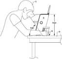
- FIG. 1is a side view illustrating a user engaged with an ophthalmic imaging device via a viewer assembly that accommodates self-alignment of the user with an optical axis of the ophthalmic imaging device, in accordance with many embodiments.
- FIG. 2is a simplified schematic side view illustration of an ophthalmic imaging device configured to be supported on a horizontal surface and orient the optical axis of the imaging device at an angle relative to the horizontal surface, in accordance with many embodiments.
- FIG. 3is a simplified schematic side view illustrating alignment of a user's eye with an optical axis of an ophthalmic imaging device with the optical axis being oriented at an angle relative to horizontal, in accordance with many embodiments.
- FIG. 4is a simplified schematic side view illustrating misalignment of a user's eye with an optical axis of an ophthalmic imaging device with the optical axis being oriented at an angle relative to horizontal, in accordance with many embodiments.
- FIG. 5shows an isometric view image of an ophthalmic imaging device, in accordance with many embodiments.
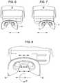
- FIG. 6shows a top view image of the ophthalmic imaging device of FIG. 5 with a viewer assembly of the imaging device positioned for imaging of a user's right eye.
- FIG. 7shows a top view image of the ophthalmic imaging device of FIG. 5 with the viewer assembly positioned for imaging of a user's left eye.
- FIG. 8shows a close-up top view image of the viewer assembly of the ophthalmic imaging device of FIG. 5 .
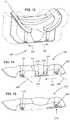
- FIG. 9is a simplified schematic illustration of the position and orientation of an interface surface of a viewer assembly of an ophthalmic imaging device relative to the optical axis of the ophthalmic imaging device, in accordance with many embodiments.
- FIG. 10is a simplified schematic illustration of the position and orientation of the interface surface of the viewer assembly of FIG. 9 and a first user with the left eye of the first user aligned with the optical axis of the ophthalmic imaging device.
- FIG. 11is a simplified schematic illustration of the position and orientation of the interface surface of the viewer assembly of FIG. 9 and a second user with the left eye of the second user aligned with the optical axis of the ophthalmic imaging device.
- FIG. 12shows an isometric view image of another ophthalmic imaging device, in accordance with many embodiments.
- FIG. 13 , FIG. 14 , and FIG. 15illustrate a locking mechanism that inhibits sliding of the viewer assembly relative to the housing assembly while the viewer assembly is engaged by the user's head, in accordance with many embodiments.
- Ophthalmic imaging devicesemploying optical coherence tomography (OCT) imaging are often employed in eye clinics image a patient's retina to monitor the progression of a retinal disease. Having to travel to an eye clinic, however, may prevent sufficient continual monitoring in some patients.
- OCToptical coherence tomography
- Such retinal diseasemay be chorio-retinal eye diseases, such as AMD, ocular hystoplasmosis, myopia, central serous retinopathy, central serous choroidopathy, glaucoma, diabetic retinopathy, retintis pigmentosa, optic neuritis, epiretinal membrane, vascular abnormalities and/or occlusions, choroidal dystrophies, retinal dystrophies, macular hole, or choroidal or retinal degeneration.
- AMDchorio-retinal eye diseases
- ocular hystoplasmosismyopia
- central serous retinopathycentral serous choroidopathy
- glaucomadiabetic retinopathy
- retintis pigmentosaoptic neuritis
- epiretinal membranevascular abnormalities and/or occlusions
- choroidal dystrophiesretinal dystrophies
- macular holeor choroidal or retinal degeneration
- an affordable ophthalmic retinal imaging devicepresents a few challenges relative to alignment of a patient's eye with an optical axis of the imaging device.
- the patient's pupilneeds to be centered (e.g., in two directions transvers to the optical axis) and stable relative to the optical axis of the imaging device throughout the imaging time period.
- the patientneeds to be fixated (e.g., gazing at a fixation target) throughout the imaging time period.
- the patient's retinaneeds to be at a suitable location along the optical axis throughout the imaging time period. Many patients, however, especially elderly patients, find it very hard to maintain suitable position and orientation of their eye relative to the imaging device through the applicable imaging time period.
- ophthalmic retinal imaging devicesthat are employed at an eye clinic typically require significant technician assistance, include pricy hardware, and/or employ sophisticated algorithms to compensate for a patient's inability to maintain suitable position and orientation of their eye relative to the imaging device through the applicable imaging time period.
- a clinicmay often employ a technician who watches a monitor in real time to monitor positions of the patient's pupil and retina, operate an alignment device to align the imaging device with the patient's eye, and/or provide instruction to the patient on what to do to align and/or maintain alignment of the imaging device with the patient's eye.
- ophthalmic imaging devicesthat include an auto-alignment system employing high scanning speed eye tracking to automatically maintain alignment of the imaging device with the patient's eye.
- Such auto-alignment systemsare typically expensive and unsuitable for mass production.
- ophthalmic imaging devicesthat employ anatomical land mark registration (blood vessels in the case or retinal imaging) to correct for movement and/or changes in orientation of the patient's eye relative to the imaging device during the imaging period.
- anatomical land mark registrationtypically employs a fundus camera, which again increases the costs of the imaging device and renders the imaging device unsuitable for mass production.
- certain regions of the eyesuch as the central portion of the macula, do not have a blood vessel suitable for use as a visible landmark.
- OCTis a scanning device that typically requires meaningful time of the patient in front of the device. (more than a few seconds)
- FIG. 1illustrates a user 12 engaged with an ophthalmic imaging device 10 , in accordance with many embodiments, via a viewer assembly 14 of the imaging device 10 .
- the viewer assembly 14accommodates alignment, by the user 12 , of an eye of the user with an optical axis of the imaging device 10 .
- the imaging device 10is configured to be placed on a horizontal surface (e.g., a top surface 16 of a table 18 ) and rest on the horizontal surface through an imaging time period of the imaging device 10 .
- the imaging device 10has an optical axis that extends at an angle from 45 degrees to 85 degrees from the horizontal surface 16 on which the ophthalmic imaging device 10 is supported.
- the viewer assembly 14is configured to interface with regions of the head of the user 12 surrounding the eyes of the user 12 (e.g., the forehead and cheeks of the user) to stabilize the user's head in a suitable position and orientation relative to the optical axis.
- the imaging device 10conducts imaging over a relatively long period of time (e.g., 30 seconds) and the user 12 engages the user's head with the viewer assembly 14 to stabilize the position and orientation of the user's head relative to the optical axis over the imaging period.
- the viewer assembly 14accommodates different positions and/or orientations of the user's head relative to the optical axis so as to enable alignment, by the user, of one of the user's eyes with the optical axis.
- the combination of the optical axis being angled relative to horizontal and the configuration of the viewer assembly 14enables the user 12 to self-align an eye of the user with the optical axis of the imaging device 10 and maintain the position of the eye relative to the optical axis over the imaging period while sitting in a natural, comfortable position.
- the combination of the optical axis being angled relative to horizontal by more than 45 degrees and the configuration of the viewer assembly 14also effectively inhibits gravity induced downward movement by the user 12 during the applicable imaging period.
- the combination of the optical axis being angled relative to the horizontal coupled with a suitable heightenables a comfortable position of the user of a desktop device, and results in a stable position with minimal drift due to gravity.
- the resulting ophthalmic imaging deviceis portable and provides a user friendly cost effective solution for at home monitoring of a retinal disease.
- the optical axis of the ophthalmic imaging deviceis angled between 45 and 85 degrees relative to the horizontal surface.
- the angle of the ophthalmic imaging device relative to the horizontal surfacecan be adjusted by the user so as to achieve a comfortable position while enabling alignment of the optical axis with the user's pupil while the user's head is positioned against the viewer.
- the ophthalmic imaging deviceis configured to be stationary when not being adjusted or moved by the user and the user can make small lateral adjustments of the user's head relative to viewer and/or the housing of the ophthalmic imaging device (e.g., in axes X and Y perpendicular to the optical axis) to align the optical axis with the user's pupil.
- the lateral movement of the user's head relative to the viewer and/or the housingis no more than 20 mm and typically in the order of 0.5 mm or less.
- the viewerhas a flexibility that accommodates lateral movement of the user's head relative to the housing.
- the viewercan incorporate a flexible material (e.g., a soft foam) in the margins of the viewer such that the user can push the user's head against one part or the viewer relative to another part of the viewer to laterally reposition the user's head relative to the housing and thereby relative to the optical axis.
- the ophthalmic imaging devicecan include a mechanism allowing the viewer to slide laterally relative to the optical axis (e.g., on axes X and/or Y perpendicular to the optical axis) such that the user can tilt and/or reposition the user's head relative to the housing to cause the viewer to slide relative to the housing to bring the user's pupil into alignment with the optical axis.
- the optical axise.g., on axes X and/or Y perpendicular to the optical axis
- FIG. 2shows a simplified schematic side view illustration of an embodiment of the ophthalmic imaging device 10 .
- the imaging device 10includes a housing assembly 20 and an imaging assembly 22 mounted to the housing assembly 20 , and the viewer assembly 14 mounted to the housing assembly 20 .
- the imaging assembly 22includes a lens assembly 24 .
- the imaging assembly 22has an optical axis 26 that is oriented at an angle relative to the top surface 16 of the table 18 .
- the optical axis 26extends at an angle from 45 degrees to 85 degrees from the horizontal surface 16 on which the ophthalmic imaging device 10 is supported.
- the imaging device 10has a focal point 28 disposed at a height between 180 mm to 350 mm above the top surface 16 .
- the imaging device 10is configured to enable the user 12 to achieve alignment of an eye 30 of the user 12 with the optical axis 26 and maintain sufficient alignment of the eye with the optical axis 26 throughout an applicable imaging period of the imaging device 10 .
- the imaging device 10is configured to enable the user 12 to achieve alignment of an eye 30 of the user 12 with the optical axis 26 and maintain sufficient alignment of the eye with the optical axis 26 throughout an applicable imaging period of the imaging device 10 .
- continued engagement of the viewer assembly 14 by the user 12 and continued fixation by the user 10 upon a fixation target displayed to the user by the imaging assembly 22can be used to help maintain alignment of the eye 30 with the optical axis 26 through the applicable imaging period of the imaging device 10 .
- the user 12is engaged with the viewer assembly 14 such that the user's eye 30 is misaligned with the optical axis 26 as illustrated in
- the user 12can reposition and/or reorient the user's head relative to the viewer assembly 14 to bring the user's eye 30 into alignment with the optical axis 26 .
- the imaging device 10repeatedly images the user's eye 30 and processes the image to determine if the user's eye 30 is aligned with the optical axis 26 or misaligned with the optical axis 26 .
- the imaging device 10provides feedback to the user 12 regarding what direction and distance the user 12 should reposition the user's eye 30 relative to the optical axis to bring the user's eye 30 into alignment with the optical axis 26 .
- FIG. 5shows an embodiment of the ophthalmic imaging device 10 .
- the imaging device 10includes an embodiment of the viewer assembly 14 , an embodiment of the housing assembly 20 , a pair of handles 32 , and a touch-screen user interface 34 .
- the housing assembly 20includes a height adjustment knob 35 and an adjustable base 36 .
- the height adjustment knob 35is drivingly coupled with the adjustable base 36 , which is adjustable via rotation of the knob 35 to change the elevation of the viewer assembly 14 relative to the horizontal surface 16 used to support the imaging device 10 .
- rotating the knob 35 in one directionincreases the elevation of the viewer assembly 14 relative to the horizontal surface 16 .
- Rotating the knob 35 in the other directiondecreases the elevation of the viewer assembly 14 relative to the horizontal surface 16 .
- the pair of handles 32are configured to be held by the user 12 to hold the viewer assembly 14 in engagement with the user's head so as to help maintain alignment of the user's eye 30 during the applicable imaging period of the imaging device 10 .
- the viewer assembly 14is repositionable relative to the housing assembly 20 between a configuration for imaging of the user's right eye and a configuration for imaging of the user's left eye.
- FIG. 6shows a top view image of the ophthalmic imaging device 10 with the viewer assembly 14 positioned for imaging of the user's right eye.
- FIG. 7shows a top view image of the ophthalmic imaging device 10 with the viewer assembly 14 positioned for imaging of a user's left eye.
- the imaging device 10includes a repositioning mechanism by which the viewer assembly 14 is coupled with the housing assembly 20 .
- the viewer assembly 14is slideably coupled with the housing assembly 20 via a repositioning mechanism that provides for sliding of the viewer assembly 14 relative to the housing assembly 20 between the respective configurations for imaging of each of the user's eyes.
- the viewer assembly 14is configured to accommodate different positions and/or orientations of the user's head relative to the optical axis 26 so as to enable alignment, by the user 12 , of the eye 30 with the optical axis 26 .
- FIG. 8shows a close-up top view image of the viewer assembly 24 of the ophthalmic imaging device 10 .
- the viewer assembly 24has gaps 38 , 40 that accommodate the user's nose for different positions and/or orientations of the user's head relative to the viewer assembly 14 .
- the gaps 38 , 40are sized to accommodate different lateral positions (i.e., parallel to axis 42 ) of the user's head and nose relative to the viewer assembly 14 .
- the gaps 38 , 40are sized to accommodate different orientations (i.e., in directions 44 ) of the user's head relative to the viewer assembly 14 .
- the depth of the recess in the viewer assembly 14 provided by the gaps 38 , 40is sized to accommodate different tilting orientations (e.g., about axis 36 ) of the user's head relative to the viewer assembly 14 and different vertical positions (perpendicular to axis 42 ) of the user's head relative to the viewer assembly 14 to enable the user to adjust the vertical position of the user's eye to enable the user to engage the user's head with the viewer assembly 14 in which the user's eye is aligned with the optical axis 26 .
- the viewer assembly 14has an interface surface 46 that is configured to engage the user's head continuously along a perimeter segment that surrounds the user's eyes.
- the perimeter segmentextends continuously from below the user's left eye, around the user's left eye between the user's left eye and the user's left ear, above the user's eyes, around the user's right eye between the user's right eye and the user's right ear, to below the user's right eye.
- the interface surface 46is configured to accommodate the different positions and/or orientations of the user's head relative to the optical axis 26 .
- the viewer assembly 14is deformable so that the shape of interface surface 46 is conformable to the user's head to accommodate the different positions and/or orientations of the user's head relative to the optical axis.
- the viewer assemblyincludes a base component, a deformable component mounted to the base component, and a biocompatible layer that covers the deformable component.
- the biocompatible layerincludes the interface surface 46 .
- the deformable componenthas different degrees of deformability in different regions of the interface surface.
- the viewer assembly 14accommodates different positions and/or orientations of each of a plurality of different user's heads relative to the optical axis 26 so as to enable alignment, by the respective user, of one of the respective user's eye with the optical axis 26 .
- the plurality of different user's accommodated by the viewer assembly 14can have a plurality of different distances by which the eyes of the respective user are separated.
- FIG. 9is a simplified schematic illustration of the position and orientation of the interface surface 46 of the viewer assembly 14 relative to the optical axis 26 and an aperture 48 of the imaging device 10 through which the imaging assembly 22 images the eye 30 .
- FIG. 9is a simplified schematic illustration of the position and orientation of the interface surface 46 of the viewer assembly 14 relative to the optical axis 26 and an aperture 48 of the imaging device 10 through which the imaging assembly 22 images the eye 30 .
- FIG. 10is a simplified schematic illustration of the position and orientation of the interface surface 46 , the optical axis 26 , and the aperture 48 relative to a first user 50 with the left eye of the first user 50 aligned with the optical axis 26 .
- FIG. 11is a simplified schematic illustration of the position and orientation of the interface surface 46 , the optical axis 26 , and the aperture 48 relative to a second user 52 with the left eye of the second user 52 aligned with the optical axis 26 .
- the eyes of the first user 50are separated by a greater distance as compared to the eyes of the second user 52 and the viewer assembly 14 accommodates use of the imaging device 10 by both the first user 50 and the second user 52 .
- FIG. 12shows an ophthalmic imaging device 110 that is configured the same as the ophthalmic imaging device 10 , except for some notable differences described herein.
- the imaging device 110includes a housing assembly 120 and a base assembly 130 instead of the housing assembly 20 and the adjustable base 36 of the imaging device 10 .
- the housing assembly 120is slideably mounted to the base assembly 130 .
- the housing assembly 120includes a lift knob 122 that is drivingly coupled with a positioning mechanism configured to selectively translate the housing assembly 120 relative to the base assembly 130 .
- the position of the housing assembly 120 relative to the base assembly 120is selectively adjustable via selective rotation of the lift knob 122 .
- the base assembly 130includes an L-shaped base member 132 configured to rest on a flat surface and provide stable support for the imaging device 110 .
- the base assembly 130includes the pair of handles 32 , which are mounted to the base member 132 .
- the pair of handles 32are configured to be held by the user 12 to hold the viewer assembly 14 in engagement with the user's head so as to help maintain alignment of the user's eye 30 during the applicable imaging period of the imaging device 110 .
- the viewer assembly 14is mounted to the housing assembly 120 , and repositionable relative to the housing assembly 120 , the same as described herein with respect to the viewer assembly 14 and the housing assembly 20 of the ophthalmic imaging device 10 , and as illustrated in FIG. 6 , FIG. 7 , and FIG. 8 .
- the touch-screen user interface 34is fixedly mounted to an upper portion of the housing assembly 120 instead of being pivotally mounted to the housing assembly 20 as in the imaging device 10 .
- the imaging device 110includes a volume control knob 140 operable to adjust volume level of audible indications and/or instructions output by the imaging device 110 , such as audible instructions to the user 12 during an imaging session.
- FIG. 13 , FIG. 14 , and FIG. 15illustrate a locking mechanism 200 that inhibits sliding of the viewer assembly 14 relative to the housing assembly 20 , 120 while the viewer assembly 14 is engaged by the user's 12 head.
- the locking mechanism 200includes a right roller 202 and a left roller 204 .
- the right roller 202is mounted to the viewer assembly 14 for rotation around a right pivot axis 206 .
- the left roller 204is mounted to the viewer assembly 14 for rotation around a left pivot axis 208 .
- the outer circumferential rolling surface of each of the right roller 202 and the left roller 204interfaces with the housing assembly 20 , 120 .
- the housing assembly 20 , 120includes a detent feature 210 that includes a left ramp 212 , a left detent groove 214 , a right ramp 216 , and a right detent groove 218 .
- the viewer assembly 14is slideably repositionable relative to the housing assembly 20 , 120 between a right eye imaging position for imaging of the user's right eye and a left eye imaging position for imaging of the user's left eye. When the viewer assembly 14 is in the right eye imaging position (as illustrated in FIG.
- the right roller 202is disposed in the right detent groove 218 .
- the force applied to the viewer assembly 14 by the user's headpushes the right roller 202 into the right detent groove 218 , which increases the amount of lateral force that would have to be applied to the viewer assembly 14 to displace the right roller 202 from the right detent groove 218 , thereby inhibiting or preventing lateral movement of the viewer assembly 14 relative to the housing assembly 20 , 120 while the user's head is rested on the viewer assembly 14 .
- each of the right roller 202 and the left roller 204include a respective O-ring that is made from a resilient material and deforms in response to the force applied to the viewer assembly 14 by the user's head so as to further inhibit displacement of the roller 202 , 204 from the respective detent groove 218 , 214 .
- the right roller 202 , the left roller 204 , and the detent feature 210are configured to accommodate repositioning of the viewer assembly 14 between the right eye imaging position and the left eye imaging position.
- the right roller 202rolls out of the right detent groove 218 and then down the right ramp 216 , and the left roller 204 then rolls up the left ramp 212 and into the left detent groove 214 .
- the left roller 204rolls out of the left detent groove 214 and then down the left ramp 212 , and the right roller 202 then rolls up the right ramp 216 and into the right detent groove 218 .
- An ophthalmic imaging devicecomprising: an imaging assembly having an optical axis; a housing assembly to which the imaging assembly is attached, wherein the housing assembly is configured to rest on a horizontal surface during operation of the imaging assembly, and wherein the optical axis is oriented at an angle from 45 degrees to 85 degrees from the horizontal surface when the housing assembly rests on the horizontal surface; and a viewer assembly coupled with the housing assembly, the viewer assembly comprising an interface surface shaped to engage a user's head to stabilize a position and an orientation of the user's head relative to the optical axis, the viewer assembly accommodating different positions and/or orientations of the user's head relative to the optical axis so as to enable alignment, by the user, of one of the user's eyes with the optical axis.
- the interface surfaceis configured to engage the user's head continuously along a perimeter segment that surrounds the user's eyes; and the perimeter segment extends continuously from below the user's left eye, around the user's left eye between the user's left eye and the user's left ear, above the user's eyes, around the user's right eye between the user's right eye and the user's right ear, to below the user's right eye.
- the viewer assemblycomprises a base component, a deformable component mounted to the base component, and a biocompatible layer that covers the deformable component; and the biocompatible layer includes the interface surface.
- the viewer assemblyaccommodates different positions and/or orientations of each of a plurality of different user's heads relative to the optical axis so as to enable alignment, by the respective user, of one of the respective user's eye with the optical axis; and the plurality of different users comprise a plurality of different distances by which the eyes of the respective user are separated.
- the imaging assemblyhas a focal point; and the focal point is disposed at a height between 180 mm to 350 mm above the horizontal surface when the housing assembly rests on the horizontal surface.
- Clause 12The ophthalmic imaging device of clause 11, wherein the housing assembly comprises a pair of legs that can be adjusted to change the height at which the focal point is disposed above the horizontal surface.
- Clause 13The ophthalmic imaging device of any of clause 10 through clause 12, wherein: the housing assembly is adjustable to simultaneously change the height at which the focal point is disposed above the horizontal surface and the orientation of the optical axis relative to the horizontal surface; and each respective height has a corresponding unique angle of the optical axis relative to the horizontal surface.
- Clause 16The ophthalmic imaging device of any preceding clause, further comprising a repositioning mechanism by which the viewer assembly is coupled to the housing assembly, the repositioning mechanism configured to enable repositioning of the viewer assembly relative to the housing assembly to enable separate alignment of each of the user's eyes with the optical axis.
- Clause 18The ophthalmic imaging device of clause 17, wherein the viewer assembly is slideably relative to the housing assembly via the repositioning mechanism in two different directions transverse to the optical axis.
- Clause 19The ophthalmic imaging device of any of clause 16 through clause 18, wherein the repositioning mechanism is operable to reposition the viewer assembly relative to the focal point parallel to the optical axis.
- Clause 21The ophthalmic imaging device of clause 20, wherein the housing assembly comprises a pair of legs that can be adjusted to change the angle at which the optical axis is oriented relative to the horizontal surface.
Landscapes
- Health & Medical Sciences (AREA)
- Life Sciences & Earth Sciences (AREA)
- Biomedical Technology (AREA)
- Heart & Thoracic Surgery (AREA)
- Veterinary Medicine (AREA)
- Biophysics (AREA)
- Ophthalmology & Optometry (AREA)
- Engineering & Computer Science (AREA)
- Public Health (AREA)
- Physics & Mathematics (AREA)
- Medical Informatics (AREA)
- Molecular Biology (AREA)
- Surgery (AREA)
- Animal Behavior & Ethology (AREA)
- General Health & Medical Sciences (AREA)
- Nuclear Medicine, Radiotherapy & Molecular Imaging (AREA)
- Radiology & Medical Imaging (AREA)
- Eye Examination Apparatus (AREA)
Abstract
Description
Claims (23)
Priority Applications (2)
| Application Number | Priority Date | Filing Date | Title |
|---|---|---|---|
| US16/404,311US11058299B2 (en) | 2017-11-07 | 2019-05-06 | Retinal imaging device and related methods |
| US17/345,228US12137977B2 (en) | 2017-11-07 | 2021-06-11 | Retinal imaging device and related methods |
Applications Claiming Priority (4)
| Application Number | Priority Date | Filing Date | Title |
|---|---|---|---|
| US201762582772P | 2017-11-07 | 2017-11-07 | |
| ILPCT/IL2018/051174 | 2018-11-04 | ||
| PCT/IL2018/051174WO2019092697A1 (en) | 2017-11-07 | 2018-11-04 | Retinal imaging device and related methods |
| US16/404,311US11058299B2 (en) | 2017-11-07 | 2019-05-06 | Retinal imaging device and related methods |
Related Parent Applications (1)
| Application Number | Title | Priority Date | Filing Date |
|---|---|---|---|
| PCT/IL2018/051174Continuation-In-PartWO2019092697A1 (en) | 2017-11-07 | 2018-11-04 | Retinal imaging device and related methods |
Related Child Applications (1)
| Application Number | Title | Priority Date | Filing Date |
|---|---|---|---|
| US17/345,228ContinuationUS12137977B2 (en) | 2017-11-07 | 2021-06-11 | Retinal imaging device and related methods |
Publications (2)
| Publication Number | Publication Date |
|---|---|
| US20190254518A1 US20190254518A1 (en) | 2019-08-22 |
| US11058299B2true US11058299B2 (en) | 2021-07-13 |
Family
ID=66438312
Family Applications (2)
| Application Number | Title | Priority Date | Filing Date |
|---|---|---|---|
| US16/404,311ActiveUS11058299B2 (en) | 2017-11-07 | 2019-05-06 | Retinal imaging device and related methods |
| US17/345,228Active2040-11-22US12137977B2 (en) | 2017-11-07 | 2021-06-11 | Retinal imaging device and related methods |
Family Applications After (1)
| Application Number | Title | Priority Date | Filing Date |
|---|---|---|---|
| US17/345,228Active2040-11-22US12137977B2 (en) | 2017-11-07 | 2021-06-11 | Retinal imaging device and related methods |
Country Status (7)
| Country | Link |
|---|---|
| US (2) | US11058299B2 (en) |
| EP (1) | EP3675711A4 (en) |
| JP (1) | JP7330993B2 (en) |
| KR (1) | KR102661654B1 (en) |
| CN (1) | CN111511268B (en) |
| CA (1) | CA3079499A1 (en) |
| WO (1) | WO2019092697A1 (en) |
Cited By (2)
| Publication number | Priority date | Publication date | Assignee | Title |
|---|---|---|---|---|
| US11556262B2 (en) | 2020-10-09 | 2023-01-17 | EMC IP Holding Company LLC | Extent operation processing |
| USD1053891S1 (en)* | 2022-09-08 | 2024-12-10 | Glaxosmithkline Intellectual Property Development Limited | Display screen with graphical user interface |
Families Citing this family (10)
| Publication number | Priority date | Publication date | Assignee | Title |
|---|---|---|---|---|
| CA3083825A1 (en) | 2017-11-07 | 2019-05-16 | Notal Vision Ltd. | Methods and systems for alignment of ophthalmic imaging devices |
| EP3675711A4 (en) | 2017-11-07 | 2021-06-30 | Notal Vision Ltd. | Retinal imaging device and related methods |
| US10595722B1 (en) | 2018-10-03 | 2020-03-24 | Notal Vision Ltd. | Automatic optical path adjustment in home OCT |
| USD921899S1 (en) | 2019-06-07 | 2021-06-08 | Welch Allyn, Inc. | Scanner |
| US10653311B1 (en) | 2019-06-12 | 2020-05-19 | Notal Vision Ltd. | Home OCT with automatic focus adjustment |
| EP4076135A1 (en)* | 2019-12-18 | 2022-10-26 | Carl Zeiss Meditec AG | Personalized patient interface for ophthalmic devices |
| US12193741B2 (en) | 2020-06-04 | 2025-01-14 | Case Western Reserve University | Using a mobile device to facilitate monitoring retinal diseases OCT methods and systems |
| GB202019278D0 (en) | 2020-12-08 | 2021-01-20 | Give Vision Ltd | Vision aid device |
| EP4565117A1 (en)* | 2022-08-04 | 2025-06-11 | Verily Life Sciences LLC | Retinal imaging system and retinal imaging adaptor and related methods of use |
| CN119138842A (en)* | 2024-11-20 | 2024-12-17 | 视微影像(河南)科技有限公司 | Fundus imaging equipment |
Citations (79)
| Publication number | Priority date | Publication date | Assignee | Title |
|---|---|---|---|---|
| US4786142A (en)* | 1986-06-16 | 1988-11-22 | Eyedentify, Inc. | Optical instrument line of sight aligning device |
| US5094521A (en)* | 1990-11-07 | 1992-03-10 | Vision Research Laboratories | Apparatus for evaluating eye alignment |
| US5838424A (en)* | 1997-02-26 | 1998-11-17 | Welch Allyn, Inc. | View port for eye test apparatus |
| US6149275A (en)* | 1998-12-03 | 2000-11-21 | Mack Products Co. | Apparatus for selection of an optical lens |
| US20030063386A1 (en)* | 2001-02-14 | 2003-04-03 | Welch Allyn, Inc. | Eye viewing device comprising eye cup |
| US6980363B1 (en) | 1999-11-08 | 2005-12-27 | Canon Kabushiki Kaisha | Image observation apparatus and system |
| US7270413B2 (en) | 2003-02-03 | 2007-09-18 | Kabushiki Kaisha Topcon | Ophthalmic data measuring apparatus, ophthalmic data measurement program and eye characteristic measuring apparatus |
| US20080259274A1 (en) | 2005-07-19 | 2008-10-23 | Chinnock Randal B | Portable digital medical camera for capturing images of the retina or the external auditory canal, and methods of use |
| US20090180074A1 (en) | 2008-01-10 | 2009-07-16 | Notal Vision Ltd. | Dual position ophthalmic apparatus |
| US20090268020A1 (en) | 2008-04-23 | 2009-10-29 | Bioptigen, Inc. | Optical Coherence Tomography (OCT) Imaging Systems for Use in Pediatric Ophthalmic Applications and Related Methods and Computer Program Products |
| US7942527B2 (en) | 2006-10-18 | 2011-05-17 | Lawrence Livermore National Security, Llc | Compact adaptive optic-optical coherence tomography system |
| US8064989B2 (en) | 2005-09-29 | 2011-11-22 | Bioptigen, Inc. | Portable optical coherence tomography (OCT) devices and related systems |
| JP2011251061A (en) | 2010-06-04 | 2011-12-15 | Topcon Corp | Ophthalmologic apparatus |
| US8098278B2 (en) | 2007-05-24 | 2012-01-17 | Kabushiki Kaisha Topcon | Optical image measurement device |
| US8348429B2 (en) | 2008-03-27 | 2013-01-08 | Doheny Eye Institute | Optical coherence tomography device, method, and system |
| US20130033593A1 (en)* | 2009-10-14 | 2013-02-07 | Chinnock Randal B | Portable Retinal Camera and Image Acquisition Method |
| US8384908B2 (en) | 2007-05-02 | 2013-02-26 | Canon Kabushiki Kaisha | Image forming method and optical coherence tomograph apparatus using optical coherence tomography |
| US8398236B2 (en) | 2010-06-14 | 2013-03-19 | Alcon Lensx, Inc. | Image-guided docking for ophthalmic surgical systems |
| US8459794B2 (en) | 2011-05-02 | 2013-06-11 | Alcon Lensx, Inc. | Image-processor-controlled misalignment-reduction for ophthalmic systems |
| US20130162948A1 (en) | 2011-12-22 | 2013-06-27 | General Electric Company | System and method for auto-ranging in optical coherence tomography |
| US8500725B2 (en) | 2009-07-29 | 2013-08-06 | Alcon Lensx, Inc. | Optical system for ophthalmic surgical laser |
| US8534837B2 (en) | 2009-05-01 | 2013-09-17 | Bioptigen, Inc. | Systems for imaging structures of a subject and related methods |
| US8534835B2 (en) | 2010-02-25 | 2013-09-17 | Nidek Co., Ltd. | Optical tomographic image photographing apparatus |
| US20140002792A1 (en) | 2009-04-24 | 2014-01-02 | Paul A. Filar | Housing for securing and optically aligning a camera to a scope, a method of attaching said housing, and a kit including said members |
| US20140009741A1 (en) | 2012-07-09 | 2014-01-09 | Arcscan, Inc. | Combination optical and ultrasonic imaging of an eye |
| US20140046193A1 (en)* | 2012-08-10 | 2014-02-13 | Matthew E. Stack | Desktop-based opto-cognitive device and system for cognitive assessment |
| JP2014073248A (en) | 2012-10-04 | 2014-04-24 | Konan Medical Inc | Ophthalmologic examination apparatus |
| US20140132924A1 (en) | 2012-11-09 | 2014-05-15 | Canon Kabushiki Kaisha | Ophthalmic apparatus and alignment determination method |
| US8804127B2 (en) | 2010-08-19 | 2014-08-12 | Canon Kabushiki Kaisha | Image acquisition apparatus, image acquisition system, and method of controlling the same |
| US20140240674A1 (en) | 2013-02-27 | 2014-08-28 | Optovue, Inc. | Automatic alignment of an imager |
| US8820931B2 (en) | 2008-07-18 | 2014-09-02 | Doheny Eye Institute | Optical coherence tomography-based ophthalmic testing methods, devices and systems |
| US8842287B2 (en) | 2011-12-22 | 2014-09-23 | General Electric Company | System and method for auto-focusing in optical coherence tomography |
| US20140340642A1 (en) | 2011-12-20 | 2014-11-20 | Postech Academy-Industry Foundation | Personal-computer-based visual-filed self-diagnosis system and visual-field self-diagnosis method |
| US8960903B2 (en) | 2011-04-27 | 2015-02-24 | Carl Zeiss Meditec, Inc. | Ultra wide-field optical coherence tomography |
| US8960905B2 (en) | 2012-01-26 | 2015-02-24 | Canon Kabushiki Kaisha | Optical tomographic apparatus and control method thereof |
| US9044166B2 (en) | 2011-04-18 | 2015-06-02 | Nidek Co., Ltd. | Optical tomographic image photographing apparatus |
| US20150208913A1 (en) | 2014-01-28 | 2015-07-30 | Canon Kabushiki Kaisha | Ophthalmologic apparatus |
| US9144379B1 (en)* | 2015-02-10 | 2015-09-29 | Clinton Norton Sims | Diagnostic method and system for detecting early age macular degeneration, maculopathies and cystoid macular edema post cataract surgery |
| US20150294147A1 (en) | 2013-05-29 | 2015-10-15 | Wavelight Gmbh | Apparatus for optical coherence tomography of an eye and method for optical coherence tomography of an eye |
| US20150292860A1 (en) | 2012-11-02 | 2015-10-15 | University Of Kent | Method and apparatus for processing the signal in spectral domain interferometry and method and apparatus for spectral domain optical coherence tomography |
| US9170087B2 (en) | 2012-03-30 | 2015-10-27 | Canon Kabushiki Kaisha | Optical coherence tomography imaging apparatus, imaging system, and control apparatus and control method for controlling imaging range in depth direction of optical coherence tomography |
| US20150305618A1 (en) | 2012-04-05 | 2015-10-29 | Bioptigen, Inc. | Surgical Microscopes Using Optical Coherence Tomography and Related Systems |
| US20150313467A1 (en) | 2012-11-30 | 2015-11-05 | Kabushiki Kaisha Topcon | Fundus imaging apparatus |
| US9186057B2 (en) | 2012-08-30 | 2015-11-17 | Canon Kabushiki Kaisha | Optical coherence tomographic imaging apparatus and control method thereof |
| US9192295B1 (en) | 2014-06-11 | 2015-11-24 | L&R Medical Inc. | Focusing algorithm in OCT-only systems |
| WO2016004385A1 (en) | 2014-07-02 | 2016-01-07 | IDx, LLC | Systems and methods for alignment of the eye for ocular imaging |
| US20160026847A1 (en) | 2014-07-24 | 2016-01-28 | Milan Vugdelija | Pupil detection |
| US9277859B2 (en) | 2013-01-31 | 2016-03-08 | Canon Kabushiki Kaisha | Optical tomographic imaging apparatus and method for controlling the same |
| US9277860B2 (en) | 2013-01-31 | 2016-03-08 | Canon Kabushiki Kaisha | Optical tomographic imaging apparatus and method for controlling the same |
| US9314154B2 (en) | 2011-10-17 | 2016-04-19 | The Board Of Trustees Of The Leland Stanford Junior University | System and method for providing analysis of visual function using a mobile device with display |
| US20160135681A1 (en) | 2012-12-10 | 2016-05-19 | Tracey Technologies, Corp. | Methods for Objectively Determining the Visual Axis of the Eye and Measuring Its Refraction |
| US20160143529A1 (en) | 2014-11-26 | 2016-05-26 | Kabushiki Kaisha Topcon | Ophthalmological apparatus |
| US20160302665A1 (en)* | 2015-04-17 | 2016-10-20 | Massachusetts Institute Of Technology | Methods and Apparatus for Visual Cues for Eye Alignment |
| US9538916B2 (en) | 2011-03-31 | 2017-01-10 | Canon Kabushiki Kaisha | Fundus inspection apparatus |
| US9565999B2 (en) | 2011-03-31 | 2017-02-14 | Canon Kabushiki Kaisha | Ophthalmologic apparatus |
| US20170071466A1 (en) | 2014-05-08 | 2017-03-16 | Mimo Ag | Method for the acquisition of optical coherence tomography image data of retina tissue of an eye of a human subject |
| US9622658B2 (en) | 2008-04-24 | 2017-04-18 | Bioptigen, Inc. | Optical coherence tomography (OCT) imaging systems having adaptable lens systems and related methods and computer program products |
| US20170172407A1 (en) | 2014-05-08 | 2017-06-22 | Mimo Ag | Optical coherence tomography imaging device for imaging a retina of a human subject |
| US20170215725A1 (en) | 2014-08-19 | 2017-08-03 | Kabushiki Kaisha Topcon | Ophthalmologic imaging apparatus and method for controlling the same |
| US20170227350A1 (en) | 2016-02-07 | 2017-08-10 | Marinko Venci Sarunic | System and Method for Dynamic Focus Control |
| US20170224208A1 (en) | 2014-10-17 | 2017-08-10 | Carl Zeiss Meditec Ag | Optical coherence tomography for performing measurements on the retina |
| US20170251920A1 (en) | 2014-08-27 | 2017-09-07 | Topcon Corporation | Ophthalmological device |
| WO2017190087A1 (en) | 2016-04-30 | 2017-11-02 | Envision Diagnostics, Inc. | Medical devices, systems, and methods for performing eye exams and eye tracking |
| US9888841B2 (en) | 2013-08-10 | 2018-02-13 | Joshua Noel Hogan | Head-mounted optical coherence tomography |
| US10048055B2 (en) | 2012-01-09 | 2018-08-14 | Samsung Electronics Co., Ltd. | Optical probe and optical coherence tomography apparatus including the same |
| US20180296087A1 (en) | 2015-05-05 | 2018-10-18 | Duke University | Systems and methods for long working distance optical coherence tomography (oct) |
| US20190090735A1 (en) | 2017-09-27 | 2019-03-28 | Topcon Corporation | Ophthalmic apparatus |
| US10327632B2 (en) | 2016-12-20 | 2019-06-25 | Novartis Ag | Systems and methods for wide field-of-view optical coherence tomography |
| WO2019147871A1 (en) | 2018-01-24 | 2019-08-01 | Duke University | Optical coherence tomography imaging systems, handheld probes, and methods that use a field curvature to match a curved surface of tissue |
| US20190254514A1 (en)* | 2016-11-07 | 2019-08-22 | Carl Zeiss Meditec Ag | A method for self-examination of an eye and ophthalmological self-examination apparatus |
| US20190313895A1 (en) | 2015-11-12 | 2019-10-17 | Tecumseh Vision, Llc | System and method for automatic assessment of disease condition using oct scan data |
| US20190368861A1 (en) | 2017-01-17 | 2019-12-05 | Duke University | Optical coherence tomography device and system |
| WO2019246412A1 (en) | 2018-06-20 | 2019-12-26 | Acucela Inc. | Miniaturized mobile, low cost optical coherence tomography system for home based ophthalmic applications |
| US10595722B1 (en) | 2018-10-03 | 2020-03-24 | Notal Vision Ltd. | Automatic optical path adjustment in home OCT |
| WO2020056454A1 (en) | 2018-09-18 | 2020-03-26 | MacuJect Pty Ltd | A method and system for analysing images of a retina |
| US10610096B2 (en) | 2016-12-21 | 2020-04-07 | Acucela Inc. | Miniaturized mobile, low cost optical coherence tomography system for home based ophthalmic applications |
| US10653309B2 (en) | 2016-12-13 | 2020-05-19 | Canon Kabushiki Kaisha | Ophthalmologic apparatus, and ophthalmologic imaging method |
| US10653314B2 (en) | 2017-11-07 | 2020-05-19 | Notal Vision Ltd. | Methods and systems for alignment of ophthalmic imaging devices |
| US10653311B1 (en) | 2019-06-12 | 2020-05-19 | Notal Vision Ltd. | Home OCT with automatic focus adjustment |
Family Cites Families (17)
| Publication number | Priority date | Publication date | Assignee | Title |
|---|---|---|---|---|
| USD390662S (en) | 1997-02-26 | 1998-02-10 | Welch Allyn, Inc. | Eye examination apparatus |
| AU2002233323A1 (en)* | 2001-02-09 | 2002-08-28 | Sensomotoric Instruments Gmbh | Multidimensional eye tracking and position measurement system |
| US6669340B2 (en)* | 2001-11-06 | 2003-12-30 | Reichert, Inc. | Alignment system for an ophthalmic instrument |
| USD614774S1 (en) | 2008-12-18 | 2010-04-27 | Tearscience, Inc. | Ocular imaging apparatus |
| USD705430S1 (en) | 2011-03-24 | 2014-05-20 | Canon Kabushiki Kaisha | Corneal tomography apparatus |
| AU2012249773A1 (en)* | 2011-04-28 | 2013-11-07 | Nexisvision, Inc. | Eye covering and refractive correction methods and apparatus having improved tear flow, comfort, and/or applicability |
| US8398238B1 (en)* | 2011-08-26 | 2013-03-19 | Alcon Lensx, Inc. | Imaging-based guidance system for ophthalmic docking using a location-orientation analysis |
| CN102551654B (en)* | 2012-01-20 | 2013-09-18 | 王毅 | Optical coherence biological measurer and method for biologically measuring eyes |
| US9060718B2 (en)* | 2012-02-13 | 2015-06-23 | Massachusetts Institute Of Technology | Methods and apparatus for retinal imaging |
| JP6101064B2 (en) | 2012-12-07 | 2017-03-22 | 株式会社トプコン | Portable optometry equipment |
| US10772497B2 (en) | 2014-09-12 | 2020-09-15 | Envision Diagnostics, Inc. | Medical interfaces and other medical devices, systems, and methods for performing eye exams |
| JP2015033472A (en)* | 2013-08-08 | 2015-02-19 | 株式会社トプコン | Ophthalmologic image-capturing apparatus |
| JP1551616S (en) | 2015-07-28 | 2016-06-13 | ||
| JP6775302B2 (en)* | 2016-02-24 | 2020-10-28 | 株式会社トプコン | Ophthalmologic imaging equipment |
| USD808527S1 (en) | 2016-04-21 | 2018-01-23 | Carl Zeiss Meditec, Inc. | Optical coherence tomography system |
| USD847345S1 (en) | 2017-04-28 | 2019-04-30 | Carl Zeiss Meditec, Inc. | Fundus imaging apparatus |
| EP3675711A4 (en) | 2017-11-07 | 2021-06-30 | Notal Vision Ltd. | Retinal imaging device and related methods |
- 2018
- 2018-11-04EPEP18876516.8Apatent/EP3675711A4/enactivePending
- 2018-11-04WOPCT/IL2018/051174patent/WO2019092697A1/ennot_activeCeased
- 2018-11-04JPJP2020544702Apatent/JP7330993B2/enactiveActive
- 2018-11-04KRKR1020207016113Apatent/KR102661654B1/enactiveActive
- 2018-11-04CACA3079499Apatent/CA3079499A1/enactivePending
- 2018-11-04CNCN201880071947.8Apatent/CN111511268B/enactiveActive
- 2019
- 2019-05-06USUS16/404,311patent/US11058299B2/enactiveActive
- 2021
- 2021-06-11USUS17/345,228patent/US12137977B2/enactiveActive
Patent Citations (104)
| Publication number | Priority date | Publication date | Assignee | Title |
|---|---|---|---|---|
| US4786142A (en)* | 1986-06-16 | 1988-11-22 | Eyedentify, Inc. | Optical instrument line of sight aligning device |
| US5094521A (en)* | 1990-11-07 | 1992-03-10 | Vision Research Laboratories | Apparatus for evaluating eye alignment |
| US5838424A (en)* | 1997-02-26 | 1998-11-17 | Welch Allyn, Inc. | View port for eye test apparatus |
| US6149275A (en)* | 1998-12-03 | 2000-11-21 | Mack Products Co. | Apparatus for selection of an optical lens |
| US6980363B1 (en) | 1999-11-08 | 2005-12-27 | Canon Kabushiki Kaisha | Image observation apparatus and system |
| US20030063386A1 (en)* | 2001-02-14 | 2003-04-03 | Welch Allyn, Inc. | Eye viewing device comprising eye cup |
| US7270413B2 (en) | 2003-02-03 | 2007-09-18 | Kabushiki Kaisha Topcon | Ophthalmic data measuring apparatus, ophthalmic data measurement program and eye characteristic measuring apparatus |
| US20080259274A1 (en) | 2005-07-19 | 2008-10-23 | Chinnock Randal B | Portable digital medical camera for capturing images of the retina or the external auditory canal, and methods of use |
| US9173563B2 (en) | 2005-09-29 | 2015-11-03 | Bioptigen, Inc. | Portable optical coherence tomography (OCT) systems |
| US8374684B2 (en) | 2005-09-29 | 2013-02-12 | Bioptigen, Inc. | Portable optical coherence tomography (OCT) devices and related systems |
| US8064989B2 (en) | 2005-09-29 | 2011-11-22 | Bioptigen, Inc. | Portable optical coherence tomography (OCT) devices and related systems |
| US7942527B2 (en) | 2006-10-18 | 2011-05-17 | Lawrence Livermore National Security, Llc | Compact adaptive optic-optical coherence tomography system |
| US8123354B2 (en) | 2006-10-18 | 2012-02-28 | Lawrence Livermore National Security, Llc | Compact adaptive optic-optical coherence tomography system |
| US8384908B2 (en) | 2007-05-02 | 2013-02-26 | Canon Kabushiki Kaisha | Image forming method and optical coherence tomograph apparatus using optical coherence tomography |
| US8098278B2 (en) | 2007-05-24 | 2012-01-17 | Kabushiki Kaisha Topcon | Optical image measurement device |
| US20090180074A1 (en) | 2008-01-10 | 2009-07-16 | Notal Vision Ltd. | Dual position ophthalmic apparatus |
| US9149182B2 (en) | 2008-03-27 | 2015-10-06 | Doheny Eye Institute | Optical coherence tomography device, method, and system |
| US8348429B2 (en) | 2008-03-27 | 2013-01-08 | Doheny Eye Institute | Optical coherence tomography device, method, and system |
| US20170049318A1 (en) | 2008-03-27 | 2017-02-23 | Doheny Eye Institute | Optical coherence tomography device, method, and system |
| US20190090733A1 (en) | 2008-03-27 | 2019-03-28 | Doheny Eye Institute | Optical coherence tomography-based ophthalmic testing methods, devices and systems |
| US10165941B2 (en) | 2008-03-27 | 2019-01-01 | Doheny Eye Institute | Optical coherence tomography-based ophthalmic testing methods, devices and systems |
| US8421855B2 (en) | 2008-04-23 | 2013-04-16 | Bioptigen, Inc. | Optical coherence tomography (OCT) imaging systems for use in pediatric ophthalmic applications and related methods and computer program products |
| US8668336B2 (en) | 2008-04-23 | 2014-03-11 | Bioptigen, Inc. | Optical coherence tomography (OCT) imaging systems for use in ophthalmic applications |
| US8860796B2 (en) | 2008-04-23 | 2014-10-14 | Bioptigen, Inc. | Optical coherence tomography (OCT) imaging systems for use in ophthalmic applications |
| US20130235344A1 (en) | 2008-04-23 | 2013-09-12 | Bioptigen, Inc. | Optical Coherence Tomography (OCT) Imaging Systems for Use in Ophthalmic Applications |
| US20090268020A1 (en) | 2008-04-23 | 2009-10-29 | Bioptigen, Inc. | Optical Coherence Tomography (OCT) Imaging Systems for Use in Pediatric Ophthalmic Applications and Related Methods and Computer Program Products |
| US20140125952A1 (en) | 2008-04-23 | 2014-05-08 | Bioptigen, Inc. | Optical Coherence Tomography (OCT) Imaging Systems for Use in Ophthalmic Applications |
| US10092180B2 (en) | 2008-04-24 | 2018-10-09 | Bioptigen, Inc. | Optical coherence tomography (OCT) imaging systems having adaptable lens systems and related methods and computer program products |
| US9622658B2 (en) | 2008-04-24 | 2017-04-18 | Bioptigen, Inc. | Optical coherence tomography (OCT) imaging systems having adaptable lens systems and related methods and computer program products |
| US9814383B2 (en) | 2008-04-24 | 2017-11-14 | Bioptigen, Inc. | Optical coherence tomography (OCT) imaging systems having adaptable lens systems and related methods and computer program products |
| US9492079B2 (en) | 2008-07-18 | 2016-11-15 | Doheny Eye Institute | Optical coherence tomography-based ophthalmic testing methods, devices and systems |
| US8820931B2 (en) | 2008-07-18 | 2014-09-02 | Doheny Eye Institute | Optical coherence tomography-based ophthalmic testing methods, devices and systems |
| US20140002792A1 (en) | 2009-04-24 | 2014-01-02 | Paul A. Filar | Housing for securing and optically aligning a camera to a scope, a method of attaching said housing, and a kit including said members |
| US8534837B2 (en) | 2009-05-01 | 2013-09-17 | Bioptigen, Inc. | Systems for imaging structures of a subject and related methods |
| US8500725B2 (en) | 2009-07-29 | 2013-08-06 | Alcon Lensx, Inc. | Optical system for ophthalmic surgical laser |
| US20130033593A1 (en)* | 2009-10-14 | 2013-02-07 | Chinnock Randal B | Portable Retinal Camera and Image Acquisition Method |
| US8534835B2 (en) | 2010-02-25 | 2013-09-17 | Nidek Co., Ltd. | Optical tomographic image photographing apparatus |
| JP2011251061A (en) | 2010-06-04 | 2011-12-15 | Topcon Corp | Ophthalmologic apparatus |
| US8398236B2 (en) | 2010-06-14 | 2013-03-19 | Alcon Lensx, Inc. | Image-guided docking for ophthalmic surgical systems |
| US8804127B2 (en) | 2010-08-19 | 2014-08-12 | Canon Kabushiki Kaisha | Image acquisition apparatus, image acquisition system, and method of controlling the same |
| US9565999B2 (en) | 2011-03-31 | 2017-02-14 | Canon Kabushiki Kaisha | Ophthalmologic apparatus |
| US9538916B2 (en) | 2011-03-31 | 2017-01-10 | Canon Kabushiki Kaisha | Fundus inspection apparatus |
| US9044166B2 (en) | 2011-04-18 | 2015-06-02 | Nidek Co., Ltd. | Optical tomographic image photographing apparatus |
| US9427151B2 (en) | 2011-04-27 | 2016-08-30 | Carl Zeiss Meditec, Inc. | Ultra wide-field optical coherence tomography |
| US8960903B2 (en) | 2011-04-27 | 2015-02-24 | Carl Zeiss Meditec, Inc. | Ultra wide-field optical coherence tomography |
| US8459794B2 (en) | 2011-05-02 | 2013-06-11 | Alcon Lensx, Inc. | Image-processor-controlled misalignment-reduction for ophthalmic systems |
| US9314154B2 (en) | 2011-10-17 | 2016-04-19 | The Board Of Trustees Of The Leland Stanford Junior University | System and method for providing analysis of visual function using a mobile device with display |
| US9572484B2 (en) | 2011-10-17 | 2017-02-21 | The Board Of Trustees Of The Leland Stanford Junior University | System and method for providing analysis of visual function using a mobile device with display |
| US20170143202A1 (en) | 2011-10-17 | 2017-05-25 | Daniel Palanker | System and method for providing analysis of visual function using a mobile device with display |
| US20140340642A1 (en) | 2011-12-20 | 2014-11-20 | Postech Academy-Industry Foundation | Personal-computer-based visual-filed self-diagnosis system and visual-field self-diagnosis method |
| US8842287B2 (en) | 2011-12-22 | 2014-09-23 | General Electric Company | System and method for auto-focusing in optical coherence tomography |
| US20130162948A1 (en) | 2011-12-22 | 2013-06-27 | General Electric Company | System and method for auto-ranging in optical coherence tomography |
| US9273950B2 (en) | 2011-12-22 | 2016-03-01 | General Electric Company | System and method for auto-ranging in optical coherence tomography |
| US10048055B2 (en) | 2012-01-09 | 2018-08-14 | Samsung Electronics Co., Ltd. | Optical probe and optical coherence tomography apparatus including the same |
| US8960905B2 (en) | 2012-01-26 | 2015-02-24 | Canon Kabushiki Kaisha | Optical tomographic apparatus and control method thereof |
| US9170087B2 (en) | 2012-03-30 | 2015-10-27 | Canon Kabushiki Kaisha | Optical coherence tomography imaging apparatus, imaging system, and control apparatus and control method for controlling imaging range in depth direction of optical coherence tomography |
| US20150305618A1 (en) | 2012-04-05 | 2015-10-29 | Bioptigen, Inc. | Surgical Microscopes Using Optical Coherence Tomography and Related Systems |
| US20140009741A1 (en) | 2012-07-09 | 2014-01-09 | Arcscan, Inc. | Combination optical and ultrasonic imaging of an eye |
| US20140046193A1 (en)* | 2012-08-10 | 2014-02-13 | Matthew E. Stack | Desktop-based opto-cognitive device and system for cognitive assessment |
| US9186057B2 (en) | 2012-08-30 | 2015-11-17 | Canon Kabushiki Kaisha | Optical coherence tomographic imaging apparatus and control method thereof |
| JP2014073248A (en) | 2012-10-04 | 2014-04-24 | Konan Medical Inc | Ophthalmologic examination apparatus |
| US20150292860A1 (en) | 2012-11-02 | 2015-10-15 | University Of Kent | Method and apparatus for processing the signal in spectral domain interferometry and method and apparatus for spectral domain optical coherence tomography |
| US20140132924A1 (en) | 2012-11-09 | 2014-05-15 | Canon Kabushiki Kaisha | Ophthalmic apparatus and alignment determination method |
| US20150313467A1 (en) | 2012-11-30 | 2015-11-05 | Kabushiki Kaisha Topcon | Fundus imaging apparatus |
| US20170042422A1 (en) | 2012-11-30 | 2017-02-16 | Kabushiki Kaisha Topcon | Fundus imaging apparatus |
| US20160135681A1 (en) | 2012-12-10 | 2016-05-19 | Tracey Technologies, Corp. | Methods for Objectively Determining the Visual Axis of the Eye and Measuring Its Refraction |
| US9277860B2 (en) | 2013-01-31 | 2016-03-08 | Canon Kabushiki Kaisha | Optical tomographic imaging apparatus and method for controlling the same |
| US9277859B2 (en) | 2013-01-31 | 2016-03-08 | Canon Kabushiki Kaisha | Optical tomographic imaging apparatus and method for controlling the same |
| US20140240674A1 (en) | 2013-02-27 | 2014-08-28 | Optovue, Inc. | Automatic alignment of an imager |
| US9420947B2 (en) | 2013-02-27 | 2016-08-23 | Optovue, Inc. | Automatic alignment of an imager |
| US20150294147A1 (en) | 2013-05-29 | 2015-10-15 | Wavelight Gmbh | Apparatus for optical coherence tomography of an eye and method for optical coherence tomography of an eye |
| US9888841B2 (en) | 2013-08-10 | 2018-02-13 | Joshua Noel Hogan | Head-mounted optical coherence tomography |
| US20150208913A1 (en) | 2014-01-28 | 2015-07-30 | Canon Kabushiki Kaisha | Ophthalmologic apparatus |
| US20170071466A1 (en) | 2014-05-08 | 2017-03-16 | Mimo Ag | Method for the acquisition of optical coherence tomography image data of retina tissue of an eye of a human subject |
| US9907466B2 (en) | 2014-05-08 | 2018-03-06 | Mimo Ag | Optical coherence tomography imaging device for imaging a retina of a human subject |
| US20170172407A1 (en) | 2014-05-08 | 2017-06-22 | Mimo Ag | Optical coherence tomography imaging device for imaging a retina of a human subject |
| US9192295B1 (en) | 2014-06-11 | 2015-11-24 | L&R Medical Inc. | Focusing algorithm in OCT-only systems |
| WO2016004385A1 (en) | 2014-07-02 | 2016-01-07 | IDx, LLC | Systems and methods for alignment of the eye for ocular imaging |
| US20160183788A1 (en) | 2014-07-02 | 2016-06-30 | IDx, LLC | Systems and methods for alignment of the eye for ocular imaging |
| US20160026847A1 (en) | 2014-07-24 | 2016-01-28 | Milan Vugdelija | Pupil detection |
| US10314480B2 (en) | 2014-08-19 | 2019-06-11 | Kabushiki Kaisha Topcon | Ophthalmologic imaging apparatus and method for controlling the same |
| US20170215725A1 (en) | 2014-08-19 | 2017-08-03 | Kabushiki Kaisha Topcon | Ophthalmologic imaging apparatus and method for controlling the same |
| US20170251920A1 (en) | 2014-08-27 | 2017-09-07 | Topcon Corporation | Ophthalmological device |
| US20170224208A1 (en) | 2014-10-17 | 2017-08-10 | Carl Zeiss Meditec Ag | Optical coherence tomography for performing measurements on the retina |
| US20160143529A1 (en) | 2014-11-26 | 2016-05-26 | Kabushiki Kaisha Topcon | Ophthalmological apparatus |
| US9144379B1 (en)* | 2015-02-10 | 2015-09-29 | Clinton Norton Sims | Diagnostic method and system for detecting early age macular degeneration, maculopathies and cystoid macular edema post cataract surgery |
| US20160302665A1 (en)* | 2015-04-17 | 2016-10-20 | Massachusetts Institute Of Technology | Methods and Apparatus for Visual Cues for Eye Alignment |
| US20180296087A1 (en) | 2015-05-05 | 2018-10-18 | Duke University | Systems and methods for long working distance optical coherence tomography (oct) |
| US20190313895A1 (en) | 2015-11-12 | 2019-10-17 | Tecumseh Vision, Llc | System and method for automatic assessment of disease condition using oct scan data |
| US10251549B2 (en) | 2016-02-07 | 2019-04-09 | Marinko Sarunic | System and method for dynamic focus control |
| US20170227350A1 (en) | 2016-02-07 | 2017-08-10 | Marinko Venci Sarunic | System and Method for Dynamic Focus Control |
| WO2017190087A1 (en) | 2016-04-30 | 2017-11-02 | Envision Diagnostics, Inc. | Medical devices, systems, and methods for performing eye exams and eye tracking |
| US20190254514A1 (en)* | 2016-11-07 | 2019-08-22 | Carl Zeiss Meditec Ag | A method for self-examination of an eye and ophthalmological self-examination apparatus |
| US10653309B2 (en) | 2016-12-13 | 2020-05-19 | Canon Kabushiki Kaisha | Ophthalmologic apparatus, and ophthalmologic imaging method |
| US10327632B2 (en) | 2016-12-20 | 2019-06-25 | Novartis Ag | Systems and methods for wide field-of-view optical coherence tomography |
| US10610096B2 (en) | 2016-12-21 | 2020-04-07 | Acucela Inc. | Miniaturized mobile, low cost optical coherence tomography system for home based ophthalmic applications |
| US20190368861A1 (en) | 2017-01-17 | 2019-12-05 | Duke University | Optical coherence tomography device and system |
| US20190090735A1 (en) | 2017-09-27 | 2019-03-28 | Topcon Corporation | Ophthalmic apparatus |
| US10653314B2 (en) | 2017-11-07 | 2020-05-19 | Notal Vision Ltd. | Methods and systems for alignment of ophthalmic imaging devices |
| WO2019147871A1 (en) | 2018-01-24 | 2019-08-01 | Duke University | Optical coherence tomography imaging systems, handheld probes, and methods that use a field curvature to match a curved surface of tissue |
| WO2019246412A1 (en) | 2018-06-20 | 2019-12-26 | Acucela Inc. | Miniaturized mobile, low cost optical coherence tomography system for home based ophthalmic applications |
| WO2020056454A1 (en) | 2018-09-18 | 2020-03-26 | MacuJect Pty Ltd | A method and system for analysing images of a retina |
| US10595722B1 (en) | 2018-10-03 | 2020-03-24 | Notal Vision Ltd. | Automatic optical path adjustment in home OCT |
| US10653311B1 (en) | 2019-06-12 | 2020-05-19 | Notal Vision Ltd. | Home OCT with automatic focus adjustment |
Non-Patent Citations (9)
| Title |
|---|
| Chakravarthy et al., "Automated Identification of Lesion Activity in Neovascular Age-Related Macular Degeneration", Opthalmology, vol. 123, No. 8, Aug. 2016, pp. 1731-1736. |
| European Patent Application No. 18876516.8, Extended European Search Report, dated Jun. 1, 2021, 10 pages. |
| PCT/IL2018/051172, "International Search Report and Written Opinion", dated Feb. 27, 2019, 12 pages. |
| PCT/IL2018/051174, "International Search Report and Written Opinion", dated Feb. 26, 2019, 8 pages. |
| U.S. Appl. No. 16/424,246, "First Action Interview Pilot Program Pre-Interview Communication", dated Jul. 31, 2019, 4 pages. |
| U.S. Appl. No. 16/425,362, "First Action Interview Pilot Program Pre-Interview Communication", dated Aug. 27, 2019, 4 pages. |
| U.S. Appl. No. 16/425,362, "Non-Final Office Action", dated Aug. 23, 2019, 13 pages. |
| U.S. Appl. No. 16/439,587, "First Action Interview Pilot Program Pre-Interview Communication", dated Aug. 30, 2019, 5 pages. |
| U.S. Appl. No. 16/439,587, "Non-Final Office Action", dated Aug. 12, 2019, 14 pages. |
Cited By (2)
| Publication number | Priority date | Publication date | Assignee | Title |
|---|---|---|---|---|
| US11556262B2 (en) | 2020-10-09 | 2023-01-17 | EMC IP Holding Company LLC | Extent operation processing |
| USD1053891S1 (en)* | 2022-09-08 | 2024-12-10 | Glaxosmithkline Intellectual Property Development Limited | Display screen with graphical user interface |
Also Published As
| Publication number | Publication date |
|---|---|
| KR102661654B1 (en) | 2024-04-29 |
| JP7330993B2 (en) | 2023-08-22 |
| CN111511268A (en) | 2020-08-07 |
| WO2019092697A1 (en) | 2019-05-16 |
| US20210369110A1 (en) | 2021-12-02 |
| CA3079499A1 (en) | 2019-05-16 |
| EP3675711A1 (en) | 2020-07-08 |
| JP2021501674A (en) | 2021-01-21 |
| CN111511268B (en) | 2023-12-26 |
| US20190254518A1 (en) | 2019-08-22 |
| EP3675711A4 (en) | 2021-06-30 |
| US12137977B2 (en) | 2024-11-12 |
| KR20200131213A (en) | 2020-11-23 |
Similar Documents
| Publication | Publication Date | Title |
|---|---|---|
| US12137977B2 (en) | Retinal imaging device and related methods | |
| US8602555B2 (en) | Method and system for treating binocular anomalies | |
| JP7569337B2 (en) | Home use OCT with automatic focus adjustment | |
| CN110381810B (en) | Screening device and method | |
| EP2618722B1 (en) | System and methods for mitigating changes in pupil size | |
| US11723536B2 (en) | Methods and systems for alignment of ophthalmic imaging devices | |
| Møller et al. | Binocular quantification and characterization of microsaccades | |
| JP2020509790A5 (en) | ||
| Mosquera et al. | Effects of torsional movements in refractive procedures | |
| US20240415386A1 (en) | Dynamic Retinal Image Quality | |
| US20240225442A1 (en) | Eye Examination Method and System | |
| KR20070026376A (en) | Hybrid eye tracking system and associated methods | |
| Goltz et al. | Vertical eye position control in darkness: orbital position and body orientation interact to modulate drift velocity | |
| KR102514933B1 (en) | A vision recovery device that massages the extraocular muscles | |
| Harris et al. | The visual consequences of deviations in the orientation of the axis of rotation of the human vestibulo-ocular reflex | |
| JP2025042308A (en) | Ophthalmic Equipment | |
| KR20220064327A (en) | Goggle shaped optical coherence tomography device | |
| CN117503045A (en) | Fundus examination auxiliary device and examination method | |
| Clément et al. | Compensatory eye movements | |
| GB2295320A (en) | Device to align head and eyes with an ophthalmic laser |
Legal Events
| Date | Code | Title | Description |
|---|---|---|---|
| FEPP | Fee payment procedure | Free format text:ENTITY STATUS SET TO UNDISCOUNTED (ORIGINAL EVENT CODE: BIG.); ENTITY STATUS OF PATENT OWNER: SMALL ENTITY | |
| FEPP | Fee payment procedure | Free format text:ENTITY STATUS SET TO SMALL (ORIGINAL EVENT CODE: SMAL); ENTITY STATUS OF PATENT OWNER: SMALL ENTITY | |
| AS | Assignment | Owner name:NOTAL VISION, LTD., ISRAEL Free format text:ASSIGNMENT OF ASSIGNORS INTEREST;ASSIGNORS:RAFAELI, OMER;RAPP, MUKI;BENYAMINI, HANOCH GIDEON;AND OTHERS;SIGNING DATES FROM 20190507 TO 20190513;REEL/FRAME:049349/0968 | |
| STPP | Information on status: patent application and granting procedure in general | Free format text:PRE-INTERVIEW COMMUNICATION MAILED | |
| STPP | Information on status: patent application and granting procedure in general | Free format text:RESPONSE TO NON-FINAL OFFICE ACTION ENTERED AND FORWARDED TO EXAMINER | |
| STPP | Information on status: patent application and granting procedure in general | Free format text:NON FINAL ACTION MAILED | |
| STPP | Information on status: patent application and granting procedure in general | Free format text:RESPONSE TO NON-FINAL OFFICE ACTION ENTERED AND FORWARDED TO EXAMINER | |
| STPP | Information on status: patent application and granting procedure in general | Free format text:FINAL REJECTION MAILED | |
| STPP | Information on status: patent application and granting procedure in general | Free format text:ADVISORY ACTION MAILED | |
| STPP | Information on status: patent application and granting procedure in general | Free format text:DOCKETED NEW CASE - READY FOR EXAMINATION | |
| STPP | Information on status: patent application and granting procedure in general | Free format text:NON FINAL ACTION MAILED | |
| STPP | Information on status: patent application and granting procedure in general | Free format text:NOTICE OF ALLOWANCE MAILED -- APPLICATION RECEIVED IN OFFICE OF PUBLICATIONS | |
| STPP | Information on status: patent application and granting procedure in general | Free format text:PUBLICATIONS -- ISSUE FEE PAYMENT RECEIVED | |
| STPP | Information on status: patent application and granting procedure in general | Free format text:AWAITING TC RESP, ISSUE FEE PAYMENT VERIFIED | |
| STPP | Information on status: patent application and granting procedure in general | Free format text:PUBLICATIONS -- ISSUE FEE PAYMENT VERIFIED | |
| STCF | Information on status: patent grant | Free format text:PATENTED CASE | |
| MAFP | Maintenance fee payment | Free format text:PAYMENT OF MAINTENANCE FEE, 4TH YR, SMALL ENTITY (ORIGINAL EVENT CODE: M2551); ENTITY STATUS OF PATENT OWNER: SMALL ENTITY Year of fee payment:4 |