US11056764B2 - Phased array antenna panel having reduced passive loss of received signals - Google Patents
Phased array antenna panel having reduced passive loss of received signalsDownload PDFInfo
- Publication number
- US11056764B2 US11056764B2US16/204,397US201816204397AUS11056764B2US 11056764 B2US11056764 B2US 11056764B2US 201816204397 AUS201816204397 AUS 201816204397AUS 11056764 B2US11056764 B2US 11056764B2
- Authority
- US
- United States
- Prior art keywords
- chip
- antennas
- output signal
- phased array
- array antenna
- Prior art date
- Legal status (The legal status is an assumption and is not a legal conclusion. Google has not performed a legal analysis and makes no representation as to the accuracy of the status listed.)
- Active, expires
Links
Images


Classifications
- H—ELECTRICITY
- H01—ELECTRIC ELEMENTS
- H01Q—ANTENNAS, i.e. RADIO AERIALS
- H01Q1/00—Details of, or arrangements associated with, antennas
- H01Q1/12—Supports; Mounting means
- H01Q1/22—Supports; Mounting means by structural association with other equipment or articles
- H01Q1/2283—Supports; Mounting means by structural association with other equipment or articles mounted in or on the surface of a semiconductor substrate as a chip-type antenna or integrated with other components into an IC package
- H—ELECTRICITY
- H01—ELECTRIC ELEMENTS
- H01Q—ANTENNAS, i.e. RADIO AERIALS
- H01Q1/00—Details of, or arrangements associated with, antennas
- H01Q1/52—Means for reducing coupling between antennas; Means for reducing coupling between an antenna and another structure
- H01Q1/521—Means for reducing coupling between antennas; Means for reducing coupling between an antenna and another structure reducing the coupling between adjacent antennas
- H01Q1/523—Means for reducing coupling between antennas; Means for reducing coupling between an antenna and another structure reducing the coupling between adjacent antennas between antennas of an array
- H—ELECTRICITY
- H01—ELECTRIC ELEMENTS
- H01Q—ANTENNAS, i.e. RADIO AERIALS
- H01Q21/00—Antenna arrays or systems
- H01Q21/06—Arrays of individually energised antenna units similarly polarised and spaced apart
- H01Q21/061—Two dimensional planar arrays
- H01Q21/065—Patch antenna array
- H—ELECTRICITY
- H01—ELECTRIC ELEMENTS
- H01Q—ANTENNAS, i.e. RADIO AERIALS
- H01Q21/00—Antenna arrays or systems
- H01Q21/24—Combinations of antenna units polarised in different directions for transmitting or receiving circularly and elliptically polarised waves or waves linearly polarised in any direction
- H—ELECTRICITY
- H01—ELECTRIC ELEMENTS
- H01Q—ANTENNAS, i.e. RADIO AERIALS
- H01Q21/00—Antenna arrays or systems
- H01Q21/0006—Particular feeding systems
- H—ELECTRICITY
- H01—ELECTRIC ELEMENTS
- H01Q—ANTENNAS, i.e. RADIO AERIALS
- H01Q25/00—Antennas or antenna systems providing at least two radiating patterns
- H01Q25/001—Crossed polarisation dual antennas
- H—ELECTRICITY
- H01—ELECTRIC ELEMENTS
- H01Q—ANTENNAS, i.e. RADIO AERIALS
- H01Q3/00—Arrangements for changing or varying the orientation or the shape of the directional pattern of the waves radiated from an antenna or antenna system
- H01Q3/26—Arrangements for changing or varying the orientation or the shape of the directional pattern of the waves radiated from an antenna or antenna system varying the relative phase or relative amplitude of energisation between two or more active radiating elements; varying the distribution of energy across a radiating aperture
Definitions
- Phased array antenna panels with large numbers of antennas and front end chips integrated on a single boardare being developed in view of higher wireless communication frequencies being used between a satellite transmitter and a wireless receiver, and also more recently in view of higher frequencies used in the evolving 5G wireless communications (5th generation mobile networks or 5th generation wireless systems).
- Phased array antenna panelsare capable of beamforming by phase shifting and amplitude control techniques, and without physically changing direction or orientation of the phased array antenna panels, and without a need for mechanical parts to effect such changes in direction or orientation.
- Phased array antenna panelsuse RF front end chips that directly interface with and collect RF signals from antennas situated adjacent to the RF front end chips. After processing the collected RF signals, the RF front end chips may provide the processed signals to a master chip that is situated relatively far from the RF front end chips. As such, relatively long transmission lines are required to carry the processed signals from the RF front end chips to the master chip. By their nature, transmission lines cause passive energy loss in the signals, especially when the transmission lines employed in the phased array antenna panel are long. Moreover, using a greater number or larger amplifiers in RF front end chips to transmit the processed signals to the master chip would increase the size, complexity, and cost of the numerous RF front end chips that are used in a phased array antenna panel. Thus, there is a need in the art for effective large-scale integration of a phased array antenna panel with reduced passive loss of signals.
- the present disclosureis directed to a phased array antenna panel having reduced passive loss of received signals, substantially as shown in and/or described in connection with at least one of the figures, and as set forth in the claims.
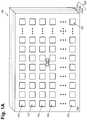
- FIG. 1Aillustrates a perspective view of a portion of an exemplary phased array antenna panel according to one implementation of the present application.
- FIG. 1Billustrates a layout diagram of a portion of an exemplary phased array antenna panel according to one implementation of the present application.
- FIG. 2illustrates a functional block diagram of a portion of an exemplary phased array antenna panel according to one implementation of the present application.
- FIG. 3Aillustrates a top view of a portion of an exemplary phased array antenna panel according to one implementation of the present application.
- FIG. 3Billustrates an exemplary circuit diagram of a portion of an exemplary combiner RF chip according to one implementation of the present application.
- FIG. 4Aillustrates a top view of a portion of an exemplary phased array antenna panel according to one implementation of the present application.
- FIG. 4Billustrates an exemplary circuit diagram of a portion of an exemplary power combiner and a portion of an exemplary combiner RF chip according to one implementation of the present application.
- FIG. 5illustrates a top view of a portion of an exemplary phased array antenna panel according to one implementation of the present application.
- FIG. 1Aillustrates a perspective view of a portion of an exemplary phased array antenna panel according to one implementation of the present application.
- phased array antenna panel 100includes substrate 102 having layers 102 a , 102 b , and 102 c , front surface 104 having front end units 105 , and master chip 180 .
- substrate 102may be a multi-layer printed circuit board (PCB) having layers 102 a , 102 b , and 102 c . Although only three layers are shown in FIG. 1A , in another implementation, substrate 102 may be a multi-layer PCB having greater or fewer than three layers.
- PCBprinted circuit board
- front surface 104 having front end units 105is formed on top layer 102 a of substrate 102 .
- substrate 102 of phased array antenna panel 100may include 500 front end units 105 , each having a radio frequency (RF) front end chip connected to a plurality of antennas (not explicitly shown in FIG. 1A ).
- phased array antenna panel 100may include 2000 antennas on front surface 104 , where each front end unit 105 includes four antennas connected to an RF front end chip (not explicitly shown in FIG. 1A ).
- master chip 180may be formed in layer 102 c of substrate 102 , where master chip 180 may be connected to front end units 105 on top layer 102 a using a plurality of control and data buses (not explicitly shown in FIG. 1A ) routed through various layers of substrate 102 .
- master chip 180is configured to provide phase shift and amplitude control signals from a digital core in master chip 180 to the RF front end chips in each of front end units 105 based on signals received from the antennas in each of front end units 105 .
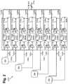
- FIG. 1Billustrates a layout diagram of a portion of an exemplary phased array antenna panel according to one implementation of the present application.
- layout diagram 190illustrates a layout of a simplified phased array antenna panel on a single printed circuit board (PCB), where master chip 180 is configured to drive in parallel four control and data buses, e.g., control and data buses 110 a , 110 b , 110 c , and 110 d , where each control and data bus is coupled to a respective antenna segment, e.g., antenna segments 111 , 113 , 115 , and 117 , where each antenna segment has four front end units, e.g., front end units 105 a , 105 b , 105 c , and 105 d in antenna segment 111 , where each front end unit includes an RF front end chip, e.g., RF front end chip 106 a in front end unit 105 a , and where each RF front end chip is coupled to four antennas, e
- front surface 104includes antennas 12 a through 12 p , 14 a through 14 p , 16 a through 16 p , and 18 a through 18 p , collectively referred to as antennas 12 - 18 .
- antennas 12 - 18may be configured to receive and/or transmit signals from and/or to one or more commercial geostationary communication satellites or low earth orbit satellites.
- antennas 12 - 18 in front surface 104may each have a square shape having dimensions of 7.5 mm by 7.5 mm, for example.
- each adjacent pair of antennas 12 - 18may be separated by a distance of a multiple integer of the quarter wavelength (i.e., n* ⁇ /4), such as 7.5 mm, 15 mm, 22.5 mm and etc.
- n* ⁇ /4integer of the quarter wavelength
- the performance of the phased array antenna panelimproves with the number of antennas 12 - 18 on front surface 104 .
- the phased array antenna panelis a flat panel array employing antennas 12 - 18 , where antennas 12 - 18 are coupled to associated active circuits to form a beam for reception (or transmission).
- the beamis formed fully electronically by means of phase control devices associated with antennas 12 - 18 .
- phased array antenna panel 100can provide fully electronic beamforming without the use of mechanical parts.
- RF front end chips 106 a through 106 pand antennas 12 a through 12 p , 14 a through 14 p , 16 a through 16 p , and 18 a through 18 p , are divided into respective antenna segments 111 , 113 , 115 , and 117 . As further illustrated in FIG. 1B , RF front end chips 106 a through 106 p , and antennas 12 a through 12 p , 14 a through 14 p , 16 a through 16 p , and 18 a through 18 p , are divided into respective antenna segments 111 , 113 , 115 , and 117 . As further illustrated in FIG.
- antenna segment 111includes front end unit 105 a having RF front end chip 106 a coupled to antennas 12 a , 14 a , 16 a , and 18 a , front end unit 105 b having RF front end chip 106 b coupled to antennas 12 b , 14 b , 16 b , and 18 b , front end unit 105 c having RF front end chip 106 c coupled to antennas 12 c , 14 c , 16 c , and 18 c , and front end unit 105 d having RF front end chip 106 d coupled to antennas 12 d , 14 d , 16 d , and 18 d .
- Antenna segment 113includes similar front end units having RF front end chip 106 e coupled to antennas 12 e , 14 e , 16 e , and 18 e , RF front end chip 106 f coupled to antennas 12 f , 14 f , 16 f , and 18 f , RF front end chip 106 g coupled to antennas 12 g , 14 g , 16 g , and 18 g , and RF front end chip 106 h coupled to antennas 12 h , 14 h , 16 h , and 18 h .
- Antenna segment 115also includes similar front end units having RF front end chip 106 i coupled to antennas 12 i , 14 i , 16 i , and 18 i , RF front end chip 106 j coupled to antennas 12 j , 14 j , 16 j , and 18 j , RF front end chip 106 k coupled to antennas 12 k , 14 k , 16 k , and 18 k , and RF front end chip 106 l coupled to antennas 12 l , 14 l , 16 l , and 18 l .
- Antenna segment 117also includes similar front end units having RF front end chip 106 m coupled to antennas 12 m , 14 m , 16 m , and 18 m , RF front end chip 106 n coupled to antennas 12 n , 14 n , 16 n , and 18 n , RF front end chip 106 o coupled to antennas 12 o , 14 o , 16 o , and 18 o , and RF front end chip 106 p coupled to antennas 12 p , 14 p , 16 p , and 18 p.
- master chip 108is configured to drive in parallel control and data buses 110 a , 110 b , 110 c , and 110 d coupled to antenna segments 111 , 113 , 115 , and 117 , respectively.
- control and data bus 110 ais coupled to RF front end chips 106 a , 106 b , 106 c , and 106 d in antenna segment 111 to provide phase shift signals and amplitude control signals to the corresponding antennas coupled to each of RF front end chips 106 a , 106 b , 106 c , and 106 d .
- Control and data buses 110 b , 110 c , and 110 dare configured to perform similar functions as control and data bus 110 a .
- master chip 180 and antenna segments 111 , 113 , 115 , and 117 having RF front end chips 106 a through 106 p and antennas 12 - 18are all integrated on a single printed circuit board.
- master chip 180may be configured to control a total of 2000 antennas disposed in ten antenna segments.
- master chip 180may be configured to drive in parallel ten control and data buses, where each control and data bus is coupled to a respective antenna segment, where each antenna segment has a set of 50 RF front end chips and a group of 200 antennas are in each antenna segment; thus, each RF front end chip is coupled to four antennas.
- each RF front end chipmay be coupled to any number of antennas, particularly a number of antennas ranging from three to sixteen.
- FIG. 2illustrates a functional block diagram of a portion of an exemplary phased array antenna panel according to one implementation of the present application.
- front end unit 205 amay correspond to front end unit 105 a in FIG. 1B of the present application.
- front end unit 205 aincludes antennas 22 a , 24 a , 26 a , and 28 a coupled to RF front end chip 206 a , where antennas 22 a , 24 a , 26 a , and 28 a and RF front end chip 206 a may correspond to antennas 12 a , 14 a , 16 a , and 18 a and RF front end chip 106 a , respectively, in FIG. 1B .
- antennas 22 a , 24 a , 26 a , and 28 amay be configured to receive signals from one or more commercial geostationary communication satellites, for example, which typically employ circularly polarized or linearly polarized signals defined at the satellite with a horizontally-polarized (H) signal having its electric-field oriented parallel with the equatorial plane and a vertically-polarized (V) signal having its electric-field oriented perpendicular to the equatorial plane.
- Hhorizontally-polarized
- Vvertically-polarized
- each of antennas 22 a , 24 a , 26 a , and 28 ais configured to provide an H output and a V output to RF front end chip 206 a.
- antenna 22 aprovides linearly polarized signal 208 a , having horizontally-polarized signal H 22 a and vertically-polarized signal V 22 a , to RF front end chip 206 a .
- Antenna 24 aprovides linearly polarized signal 208 b , having horizontally-polarized signal H 24 a and vertically-polarized signal V 24 a , to RF front end chip 206 a .
- Antenna 26 aprovides linearly polarized signal 208 c , having horizontally-polarized signal H 26 a and vertically-polarized signal V 26 a , to RF front end chip 206 a .
- Antenna 28 aprovides linearly polarized signal 208 d , having horizontally-polarized signal H 28 a and vertically-polarized signal V 28 a , to RF front end chip 206 a.
- horizontally-polarized signal H 22 a from antenna 22 ais provided to a receiving chip having low noise amplifier (LNA) 222 a , phase shifter 224 a and variable gain amplifier (VGA) 226 a , where LNA 222 a is configured to generate an output to phase shifter 224 a , and phase shifter 224 a is configured to generate an output to VGA 226 a .
- LNAlow noise amplifier
- VGAvariable gain amplifier
- vertically-polarized signal V 22 a from antenna 22 ais provided to a receiving chip including low noise amplifier (LNA) 222 b , phase shifter 224 b and variable gain amplifier (VGA) 226 b , where LNA 222 b is configured to generate an output to phase shifter 224 b , and phase shifter 224 b is configured to generate an output to VGA 226 b.
- LNAlow noise amplifier
- VGAvariable gain amplifier
- horizontally-polarized signal H 24 a from antenna 24 ais provided to a receiving chip having low noise amplifier (LNA) 222 c , phase shifter 224 c and variable gain amplifier (VGA) 226 c , where LNA 222 c is configured to generate an output to phase shifter 224 c , and phase shifter 224 c is configured to generate an output to VGA 226 c .
- LNAlow noise amplifier
- VGAvariable gain amplifier
- vertically-polarized signal V 24 a from antenna 24 ais provided to a receiving chip including low noise amplifier (LNA) 222 d , phase shifter 224 d and variable gain amplifier (VGA) 226 d , where LNA 222 d is configured to generate an output to phase shifter 224 d , and phase shifter 224 d is configured to generate an output to VGA 226 d.
- LNAlow noise amplifier
- VGAvariable gain amplifier
- horizontally-polarized signal H 26 a from antenna 26 ais provided to a receiving chip having low noise amplifier (LNA) 222 e , phase shifter 224 e and variable gain amplifier (VGA) 226 e , where LNA 222 e is configured to generate an output to phase shifter 224 e , and phase shifter 224 e is configured to generate an output to VGA 226 e .
- LNAlow noise amplifier
- VGAvariable gain amplifier
- vertically-polarized signal V 26 a from antenna 26 ais provided to a receiving chip including low noise amplifier (LNA) 222 f , phase shifter 224 f and variable gain amplifier (VGA) 226 f , where LNA 222 f is configured to generate an output to phase shifter 224 f , and phase shifter 224 f is configured to generate an output to VGA 226 f.
- LNAlow noise amplifier
- VGAvariable gain amplifier
- horizontally-polarized signal H 28 a from antenna 28 ais provided to a receiving chip having low noise amplifier (LNA) 222 g , phase shifter 224 g and variable gain amplifier (VGA) 226 g , where LNA 222 g is configured to generate an output to phase shifter 224 g , and phase shifter 224 g is configured to generate an output to VGA 226 g .
- LNAlow noise amplifier
- VGAvariable gain amplifier
- vertically-polarized signal V 28 a from antenna 28 ais provided to a receiving chip including low noise amplifier (LNA) 222 h , phase shifter 224 h and variable gain amplifier (VGA) 226 h , where LNA 222 h is configured to generate an output to phase shifter 224 h , and phase shifter 224 h is configured to generate an output to VGA 226 h.
- LNAlow noise amplifier
- VGAvariable gain amplifier
- control and data bus 210 awhich may correspond to control and data bus 110 a in FIG. 1B , is provided to RF front end chip 206 a , where control and data bus 210 a is configured to provide phase shift signals to phase shifters 224 a , 224 b , 224 c , 224 d , 224 e , 224 f , 224 g , and 224 h in RF front end chip 206 a to cause a phase shift in at least one of these phase shifters, and to provide amplitude control signals to VGAs 226 a , 226 b , 226 c , 226 d , 226 e , 226 f , 226 g , and 226 h , and optionally to LNAs 222 a , 222 b , 222 c , 222 d , 222 e , 222 f , 222 g , and
- control and data bus 210 ais also provided to other front end units, such as front end units 105 b , 105 c , and 105 d in segment 111 of FIG. 1B .
- at least one of the phase shift signals carried by control and data bus 210 ais configured to cause a phase shift in at least one linearly polarized signal, e.g., horizontally-polarized signals H 22 a through H 28 a and vertically-polarized signals V 22 a through V 28 a , received from a corresponding antenna, e.g., antennas 22 a , 24 a , 26 a , and 28 a.
- amplified and phase shifted horizontally-polarized signals H′ 22 a , H′ 24 a , H′ 26 a , and H′ 28 a in front end unit 205 amay be provided to a summation block (not explicitly shown in FIG.
- amplified and phase shifted vertically-polarized signals V′ 22 a , V′ 24 a , V′ 26 a , and V′ 28 a in front end unit 205 aand other amplified and phase shifted vertically-polarized signals from the other front end units, e.g.
- front end units 105 b , 105 c , and 105 d as well as front end units in antenna segments 113 , 115 , and 117 shown in FIG. 1Bmay be provided to a summation block (not explicitly shown in FIG. 2 ), that is configured to sum all of the powers of the amplified and phase shifted horizontally-polarized signals, and combine all of the phases of the amplified and phase shifted horizontally-polarized signals, to provide a V-combined output to a master chip such as master chip 180 in FIG. 1 .
- FIG. 3Aillustrates a top view of a portion of an exemplary phased array antenna panel according to one implementation of the present application.
- exemplary phased array antenna panel 300includes substrate 302 , RF front end chips 310 and 320 , antennas 312 a , 312 b , 312 c , 312 d , 312 e 312 f , 312 g , and 312 h , collectively referred to as antennas 312 , probes 314 a -V, 314 a -H, 314 b -V, 314 c -H, 314 d -V, 314 d -H, 314 e -V, 314 e -H, 314 f -V, 314 f -H, 314 g -H, and 314 h -V, collectively referred to as probes 314 , electrical connectors 316 a , 316 b ,
- antennas 312are arranged on the top surface of substrate 302 .
- antennas 312have substantially square shapes, or substantially rectangular shapes, and are aligned with each other.
- the distance between each antenna and an adjacent antennais a fixed distance.
- fixed distance D 1separates various adjacent antennas.
- distance D 1may be a quarter wavelength (i.e., ⁇ /4).
- Antennas 312may be, for example, cavity antennas or patch antennas or other types of antennas.
- the shape of antennas 312may correspond to, for example, the shape of an opening in a cavity antenna or the shape of an antenna plate in a patch antenna.
- antennas 312may have substantially circular shapes, or may have any other shapes. In some implementations, some of antennas 312 may be offset rather than aligned. In various implementations, distance D 1 may be less than or greater than a quarter wavelength (i.e., less than or greater than ⁇ /4), or the distance between each antenna and an adjacent antenna might not be a fixed distance.
- RF front end chips 310 and 320are arranged on the top surface of substrate 302 .
- RF front end chip 310is adjacent to antennas 312 a , 312 b , 312 c , and 312 d .
- RF front end chip 320is adjacent to antennas 312 e , 312 f , 312 g , and 312 h .
- each of RF front end chips 310 and 320is adjacent to four antennas.
- RF front end chip 310may be substantially centered or generally between antennas 312 a , 312 b , 312 c , and 312 d .
- RF front end chip 320may be substantially centered or generally between antennas 312 e , 312 f , 312 g , and 312 h . In other implementations, each of RF front end chips 310 and 320 may be between a number of adjacent antennas that is fewer than four or greater than four.
- FIG. 3Aillustrates probes 314 disposed in antennas 312 .
- probes 314may or may not be completely flush at the corners of antennas 312 .
- distance D 2may separate probe 314 a -H the corner of antenna 312 a adjacent to RF front end chip 310 .
- Distance D 2may be, for example, a distance that allows tolerance during production or alignment of probes 314 .
- the distance between RF front end chip 310 and probe 314 a -Hmay be less than approximately 2 millimeters.
- FIG. 3Afurther illustrates exemplary orientations of an x-axis (e.g., x-axis 362 ) and a perpendicular, or substantially perpendicular, y-axis (e.g., y-axis 364 ).
- Each of antennas 312may have two probes, one probe parallel to x-axis 362 and the other probe parallel to y-axis 364 .
- antenna 312 dhas probe 314 d -H parallel to x-axis 362 , and probe 314 d -V parallel to y-axis 364 .
- each of antennas 312may have one horizontally-polarized probe and one vertically-polarized probe.
- each of antennas 312may have any number of probes 314 , and probes 314 may have any orientations and polarizations.
- FIG. 3Afurther shows electrical connectors 316 a , 316 b , 316 c , and 316 d , coupling probes 314 a -H, 314 b -V, 314 c -H, and 314 d -V to RF front end chip 310 , as well as electrical connectors 316 e , 316 f , 316 g , and 316 h , coupling probes 314 e -H, 314 f -V, 314 g -H, and 314 h -V to RF front end chip 320 .
- electrical connectors 316 e , 316 f , 316 g , and 316 hcoupling probes 314 e -H, 314 f -V, 314 g -H, and 314 h -V to RF front end chip 320 .
- the dashed circlessuch as dashed circle 382 , surround each RF front end chip and its coupled probes.
- Electrical connectors 316may be, for example, traces in substrate 302 .
- Electrical connectors 316 a , 316 b , 316 c , and 316 dprovide input signals to RF front end chip 310 from respective antennas 312 a , 312 b , 312 c , and 312 d .
- Electrical connectors 316 e , 316 f , 316 g , and 316 hprovide input signals to RF front end chip 320 from respective antennas 312 e , 312 f , 312 g , and 312 h .
- each of RF front end chips 310 and 320receives four input signals from four respective antennas. As stated above, RF front end chips 310 and 320 produce output signals based on these input signals. As stated above, a master chip (not shown in FIG. 3A ) may provide phase shift and amplitude control signals to antennas 312 through RF front end chips 310 and 320 . In other implementations, each of RF front end chips 310 and 320 may receive a number of input signals that is fewer than four or greater than four. In other implementations, each of RF front end chips 310 and 320 may receive more than one input signal from each of antennas 312 .
- FIG. 3Afurther illustrates signal lines 318 and 328 coupling respective RF front end chips 310 and 320 to combiner RF chip 330 .
- Signal lines 318 and 328may be, for example, traces in substrate 302 .
- signal lines 318 and 328each provide an output signal from respective RF front end chips 310 and 320 to combiner RF chip 330 .
- each of RF front end chips 310 and 320may produce more than one output signal, and more signal lines may be used.
- combiner RF chip 330is arranged on the top surface of substrate 302 , substantially centered between RF front end chips 310 and 320 .
- the combiner RF chipmay be arranged in substrate 302 , or may not be substantially centered between RF front end chips 310 and 320 .
- FIG. 3Billustrates an exemplary circuit diagram of a portion of an exemplary combiner RF chip according to one implementation of the present application.
- exemplary combiner RF chip 330receives signal lines 318 and 328 , and includes optional input buffers 332 and 334 , exemplary power combiner 340 , power combined output line 348 , optional output buffer 336 , and buffered power combined output line 338 .
- Combiner RF chip 330 in FIG. 3Bcorresponds to combiner RF chip 330 in FIG. 3A .
- Signal lines 318 and 328 in FIG. 3Bcorrespond to respective signal lines 318 and 328 in FIG. 3A received from respective RF front end chips 310 and 320 in FIG. 3A .
- Signal lines 318 and 328are fed into respective optional input buffers 332 and 334 on combiner RF chip 330 .
- Input buffers 332 and 334may be, for example, LNAs (“low noise amplifiers”).
- Input buffers 332 and 334may provide gain and noise reduction to signals received from signal lines 318 and 328 .
- power combiner 340is arranged on combiner RF chip 330 .
- Power combiner 340includes on-chip resistor R 1 , on-chip inductors L 1 and L 2 , on-chip capacitors C 1 , C 2 , and C 3 , and nodes 342 , 344 , and 346 .
- Signal lines 318 and 328are fed into power combiner 340 at respective nodes 342 and 344 .
- On-chip resistor R 1is coupled between nodes 342 and 344 .
- On-chip inductor L 1is coupled between nodes 342 and 346 .
- On-chip inductor L 2is coupled between nodes 344 and 346 .
- On-chip capacitor C 1is coupled between node 342 and ground.
- On-chip capacitor C 2is coupled between node 344 and ground.
- On-chip capacitor C 3is coupled between node 346 and ground.
- Node 346is coupled to power combined output line 348 .
- the impedance, inductance and capacitance values for on-chip resistor R 1 , on-chip inductors L 1 and L 2 , and on-chip capacitors C 1 , C 2 , and C 3may be chosen such that the impedance of each of signal lines 318 and 328 , or the output impedance of optional buffers 332 and 334 , in case such optional buffers are used, is matched to the impedance of power combined output line 348 .
- power combiner 340is a lumped-element power combiner. In other implementations, power combiner 340 may be a microstrip power combiner, or any other power combiner.
- power combiner 340 on combiner RF chip 330produces a power combined output signal at power combined output line 348 .
- Power combined output signal at power combined output line 348is a combination of powers of signals at signal lines 318 and 328 .
- Signal lines 318 and 328 in FIG. 3Bcorrespond to output signals of respective RF front end chips 310 and 320 in FIG. 3A , as stated above.
- the power combined output signal at power combined output line 348is a combination of powers of output signals from RF front end chips 310 and 320 .
- Power combined output line 348may then be fed into other circuitry in combiner RF chip 330 or directly into transmission lines of phased array antenna panel 300 .
- combiner RF chip 330receives output signals of RF front end chips 310 and 320 and produces a power combined output signal that is a combination of powers of those output signals, a higher power signal can be fed into a transmission line driven by power combined output line 348 , or if optional output buffer 336 is used, driven by buffered power combined output line 338 .
- relatively short transmission linesfor signal lines 318 and 328 ) are used for each output signal of RF front end chips 310 and 320 .
- phased array antenna panel 300achieves reduced passive signal loss.
- FIG. 3Balso illustrates power combined output line from power combiner 340 fed into optional output buffer 336 .
- Output buffer 336may be, for example, a unity gain buffer, an amplifier, or an op-amp. Output buffer 336 may increase the resilience of power combiner 340 , especially against subsequent loads in phased array antenna panel 300 .
- Output buffer 336 in combiner RF chip 330generates a buffered power combined output signal at buffered power combined output line 338 based on power combined output signal at power combined output line 348 .
- combiner RF chip 330receives output signals of RF front end chips 310 and 320 and can produce a buffered power combined output line 338 that is a combination of powers of those output signals, an output buffer is not required for each output signal of RF front end chips 310 and 320 .
- phased array antenna panel 300achieves reduced number of active amplifier circuits.
- FIG. 4Aillustrates a top view of a portion of an exemplary phased array antenna panel according to one implementation of the present application.
- exemplary phased array antenna panel 400includes substrate 402 , RF front end chips 410 and 420 , antennas 412 a , 412 b , 412 c , 412 d , 412 e 412 f , 412 g , and 412 h , collectively referred to as antennas 412 , probes 414 a -V, 414 a -H, 414 b -V, 414 c -H, 414 d -V, 414 d -H, 414 e -V, 414 e -H, 414 f -V, 414 f -H, 414 g -H, and 414 h -V, collectively referred to as probes 414 , electrical connectors 416 a , 416 b , 416 c , 4
- antennas 412are arranged on the top surface of substrate 402 .
- antennas 412have substantially square shapes, or substantially rectangular shapes, and are aligned with each other.
- the distance between each antenna and an adjacent antennais a fixed distance.
- fixed distance D 1separates various adjacent antennas.
- distance D 1may be a quarter wavelength (i.e., ⁇ /4).
- Antennas 412may be, for example, cavity antennas or patch antennas or other types of antennas.
- the shape of antennas 412may correspond to, for example, the shape of an opening in a cavity antenna or the shape of an antenna plate in a patch antenna.
- antennas 412may have substantially circular shapes, or may have any other shapes. In some implementations, some of antennas 412 may be offset rather than aligned. In various implementations, distance D 1 may be less than or greater than a quarter wavelength (i.e., less than or greater than ⁇ /4), or the distance between each antenna and an adjacent antenna might not be a fixed distance.
- RF front end chips 410 and 420are arranged on the top surface of substrate 402 .
- RF front end chip 410is adjacent to antennas 412 a , 412 b , 412 c , and 412 d .
- RF front end chip 420is adjacent to antennas 412 e , 412 f , 412 g , and 412 h .
- each of RF front end chips 410 and 420is adjacent to four antennas.
- RF front end chip 410may be substantially centered or generally between antennas 412 a , 412 b , 412 c , and 412 d .
- RF front end chip 420may be substantially centered or generally between antennas 412 e , 412 f , 412 g , and 412 h . In other implementations, each of RF front end chips 410 and 420 may be between a number of adjacent antennas that is fewer than four or greater than four.
- FIG. 4Aillustrates probes 414 disposed in antennas 412 .
- probes 414may or may not be completely flush at the corners of antennas 412 .
- distance D 2may separate probe 414 a -H from the corner of antenna 412 a adjacent to RF front end chip 410 .
- Distance D 2may be, for example, a distance that allows tolerance during production or alignment of probes 414 .
- the distance between RF front end chip 410 and probe 414 a -Hmay be less than approximately 2 millimeters.
- FIG. 4Afurther illustrates exemplary orientations of an x-axis (e.g., x-axis 462 ) and a perpendicular, or substantially perpendicular, y-axis (e.g., y-axis 464 ).
- Each of antennas 412may have two probes, one probe parallel to x-axis 462 and the other probe parallel to y-axis 464 .
- antenna 412 dhas probe 414 d -H parallel to x-axis 462 , and probe 414 d -V parallel to y-axis 464 .
- each of antennas 412may have one horizontally-polarized probe and one vertically-polarized probe.
- each of antennas 412may have any number of probes 414 , and probes 414 may have any orientations and polarizations.
- FIG. 4Afurther shows electrical connectors 416 a , 416 b , 416 c , and 416 d , coupling probes 414 a -H, 414 b -V, 414 c -H, and 414 d -V to RF front end chip 410 , as well as electrical connectors 416 e , 416 f , 416 g , and 416 h , coupling probes 414 e -H, 414 f -V, 414 g -H, and 414 h -V to RF front end chip 420 .
- electrical connectors 416 e , 416 f , 416 g , and 416 hcoupling probes 414 e -H, 414 f -V, 414 g -H, and 414 h -V to RF front end chip 420 .
- the dashed circlessuch as dashed circle 482 , surround each RF front end chip and its coupled probes.
- Electrical connectors 416may be, for example, traces in substrate 402 .
- Electrical connectors 416 a , 416 b , 416 c , and 416 dprovide input signals to RF front end chip 410 from respective antennas 412 a , 412 b , 412 c , and 412 d .
- Electrical connectors 416 e , 416 f , 416 g , and 416 hprovide input signals to RF front end chip 420 from respective antennas 412 e , 412 f , 412 g , and 412 h .
- each of RF front end chips 410 and 420receives four input signals from four respective antennas. As stated above, RF front end chips 410 and 420 produce output signals based on these input signals. As stated above, a master chip (not shown in FIG. 4A ) may provide phase shift and amplitude control signals to antennas 412 through RF front end chips 410 and 420 . In other implementations, each of RF front end chips 410 and 420 may receive a number of input signals that is fewer than four or greater than four. In other implementations, each of RF front end chips 410 and 420 may receive more than one input signal from each of antennas 412 .
- FIG. 4Afurther illustrates signal lines 418 and 428 coupling respective RF front end chips 410 and 420 to power combiner 440 .
- Signal lines 418 and 428may be, for example, traces in substrate 402 .
- signal lines 418 and 428each provide an output signal from respective RF front end chips 410 and 420 to power combiner 440 .
- each of RF front end chips 410 and 420may produce more than one output signal, and more signal lines may be used.
- Power combiner 440is coupled to combiner RF chip 430 .
- Combiner RF chip 430receives a power combined output signal from power combiner 440 , as described below.
- power combiner 440 and combiner RF chip 430are arranged on the top surface of substrate 402 , substantially centered between RF front end chips 410 and 420 .
- power combiner 440 and/or combiner RF chip 430may be arranged in substrate 402 , or may not be substantially centered between RF front end chips 410 and 420 .
- FIG. 4Billustrates exemplary circuit diagrams of a portion of an exemplary power combiner and a portion of an exemplary combiner RF chip according to one implementation of the present application.
- exemplary power combiner 440receives signal lines 418 and 428 , and includes resistor R 2 , microstrips M 1 and M 2 , nodes 442 , 444 , and 446 , and power combined output line 448 .
- Power combiner 440 in FIG. 4Bcorresponds to power combiner 440 in FIG. 4A .
- Signal lines 418 and 428 in FIG. 4Bcorrespond to respective signal lines 418 and 428 in FIG. 4A , and receive output signals from respective RF front end chips 410 and 420 in FIG. 4A .
- Signal lines 418 and 428are fed into power combiner 440 at respective nodes 442 and 444 .
- Resistor R 2is coupled between nodes 442 and 444 .
- Microstrip M 1is coupled between nodes 442 and 446 .
- Microstrip M 2is coupled between nodes 444 and 446 .
- Node 446is coupled to power combined output line 448 .
- Characteristic impedance values for resistor R 2 and microstrips M 1 and M 2may be chosen such that the impedance of each of signal lines 418 and 428 is matched to the impedance of power combined output line 448 .
- resistor R 2may have an impedance equal to twice the impedance of each of signal lines 418 and 428 (i.e., 2*Z 0 ), and each of microstrips M 1 and M 2 may have a length equal to a quarter wavelength (i.e., ⁇ /4) and an impedance equal to the impedance of each of signal lines 418 and 428 times the square root of two (i.e., ⁇ 2*Z 0 ).
- power combiner 440is a microstrip power combiner. In other implementations, power combiner 440 may be a lumped-element power combiner, or any other power combiner.
- power combiner 440produces a power combined output signal at power combined output line 448 .
- Power combined output signal at power combined output line 448is a combination of powers of signals at signal lines 418 and 428 .
- Signal lines 418 and 428 in FIG. 4Bcorrespond to output signals of respective RF front end chips 410 and 420 in FIG. 4A , as stated above.
- the power combined output signal at power combined output line 448is a combination of powers of output signals from RF front end chips 410 and 420 .
- power combined output signal at power combined output line 448may be a combination of powers of more than two output signals from any number of RF front end chips.
- exemplary combiner RF chip 430receives power combined output line 448 , and includes optional input buffer 432 and optional output buffer 436 , and buffered power combined output line 438 .
- Combiner RF chip 430 in FIG. 4Bcorresponds to combiner RF chip 430 in FIG. 4A .
- Combiner RF chip 430receives a power combined output signal from power combiner 440 at power combined output line 448 .
- Power combined output line 448is fed into optional input buffer 432 on combiner RF chip 430 .
- Input buffer 432may be, for example, an LNA. Input buffer 432 may provide gain and noise reduction to signals received from power combined output line 448 .
- FIG. 4Balso illustrates power combined output line 448 fed into optional output buffer 436 .
- Output buffer 436may be, for example, a unity gain buffer, an amplifier, or an op-amp. Output buffer 436 may increase the resilience of power combiner 440 , especially against subsequent loads in phased array antenna panel 400 .
- Output buffer 436 in combiner RF chip 430generates a buffered power combined output signal at line 438 based on power combined output signal received from line 448 . Power combined output line 448 may then be fed into transmission lines of phased array antenna panel 400 .
- combiner RF chip 430receives a power combined output signal that is a combination of powers of output signals of RF front end chips 410 and 420 , a higher power signal can be fed into a transmission line driven by power combined output line 448 .
- relatively short transmission linesfor signal lines 418 and 428 ) are used for each output signal of RF front end chips 410 and 420 .
- phased array antenna panel 400achieves reduced passive signal loss.
- combiner RF chip 430receives output signals of RF front end chips 410 and 420 and can produce a buffered power combined output line 438 that is a combination of powers of those output signals, an output buffer is not required for each output signal of RF front end chips 410 and 420 .
- phased array antenna panel 400achieves reduced number of active amplifier circuits.
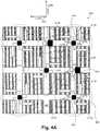
- FIG. 5illustrates a top view of a portion of an exemplary phased array antenna panel according to one implementation of the present application.
- FIG. 5illustrates a large-scale implementation of the present application.
- Numerous antennas, RF front end chips, their corresponding probes, and combiner RF chipsare arranged on phased array antenna panel 500 .
- Dashed circle 582 in FIG. 5may correspond to dashed circle 382 in FIG. 3A , which encloses probes 314 e -H, 314 f -V, 314 g -H, and 314 h -V, or may correspond to dashed circle 482 in FIG.
- phased array antenna panel 500may be a substantially square module having dimensions of eight inches by eight inches. In other implementations, phased array antenna panel module may have any other shape or dimensions.
- RF front end chips, combiner RF chips, antennas, electrical connectors, probes, and distances in relation to any elements discussed in FIG. 3 or 4may also apply to the large-scale implementation shown in phased array antenna panel 500 in FIG. 5 .
Landscapes
- Engineering & Computer Science (AREA)
- Microelectronics & Electronic Packaging (AREA)
- Variable-Direction Aerials And Aerial Arrays (AREA)
Abstract
Description
Claims (16)
Priority Applications (3)
| Application Number | Priority Date | Filing Date | Title |
|---|---|---|---|
| US16/204,397US11056764B2 (en) | 2016-11-18 | 2018-11-29 | Phased array antenna panel having reduced passive loss of received signals |
| US17/230,696US11664582B2 (en) | 2016-11-18 | 2021-04-14 | Phased array antenna panel having reduced passive loss of received signals |
| US18/323,002US12155113B2 (en) | 2016-11-18 | 2023-05-24 | Phased array antenna panel having reduced passive loss of received signals |
Applications Claiming Priority (2)
| Application Number | Priority Date | Filing Date | Title |
|---|---|---|---|
| US15/356,172US10199717B2 (en) | 2016-11-18 | 2016-11-18 | Phased array antenna panel having reduced passive loss of received signals |
| US16/204,397US11056764B2 (en) | 2016-11-18 | 2018-11-29 | Phased array antenna panel having reduced passive loss of received signals |
Related Parent Applications (1)
| Application Number | Title | Priority Date | Filing Date |
|---|---|---|---|
| US15/356,172ContinuationUS10199717B2 (en) | 2016-11-18 | 2016-11-18 | Phased array antenna panel having reduced passive loss of received signals |
Related Child Applications (1)
| Application Number | Title | Priority Date | Filing Date |
|---|---|---|---|
| US17/230,696ContinuationUS11664582B2 (en) | 2016-11-18 | 2021-04-14 | Phased array antenna panel having reduced passive loss of received signals |
Publications (2)
| Publication Number | Publication Date |
|---|---|
| US20190097305A1 US20190097305A1 (en) | 2019-03-28 |
| US11056764B2true US11056764B2 (en) | 2021-07-06 |
Family
ID=62147854
Family Applications (4)
| Application Number | Title | Priority Date | Filing Date |
|---|---|---|---|
| US15/356,172ActiveUS10199717B2 (en) | 2016-11-18 | 2016-11-18 | Phased array antenna panel having reduced passive loss of received signals |
| US16/204,397Active2037-05-22US11056764B2 (en) | 2016-11-18 | 2018-11-29 | Phased array antenna panel having reduced passive loss of received signals |
| US17/230,696Active2036-12-13US11664582B2 (en) | 2016-11-18 | 2021-04-14 | Phased array antenna panel having reduced passive loss of received signals |
| US18/323,002ActiveUS12155113B2 (en) | 2016-11-18 | 2023-05-24 | Phased array antenna panel having reduced passive loss of received signals |
Family Applications Before (1)
| Application Number | Title | Priority Date | Filing Date |
|---|---|---|---|
| US15/356,172ActiveUS10199717B2 (en) | 2016-11-18 | 2016-11-18 | Phased array antenna panel having reduced passive loss of received signals |
Family Applications After (2)
| Application Number | Title | Priority Date | Filing Date |
|---|---|---|---|
| US17/230,696Active2036-12-13US11664582B2 (en) | 2016-11-18 | 2021-04-14 | Phased array antenna panel having reduced passive loss of received signals |
| US18/323,002ActiveUS12155113B2 (en) | 2016-11-18 | 2023-05-24 | Phased array antenna panel having reduced passive loss of received signals |
Country Status (1)
| Country | Link |
|---|---|
| US (4) | US10199717B2 (en) |
Cited By (14)
| Publication number | Priority date | Publication date | Assignee | Title |
|---|---|---|---|---|
| US20210234257A1 (en)* | 2016-11-18 | 2021-07-29 | Movandi Corporation | Phased Array Antenna Panel Having Reduced Passive Loss of Received Signals |
| US20210351516A1 (en) | 2018-12-26 | 2021-11-11 | Movandi Corporation | Lens-enhanced communication device |
| US20220085851A1 (en) | 2017-12-07 | 2022-03-17 | Movandi Corporation | Optimized multi-beam antenna array network with an extended radio frequency range |
| US11502424B2 (en) | 2016-09-02 | 2022-11-15 | Silicon Valley Bank | Wireless transceiver having receive antennas and transmit antennas with orthogonal polarizations in a phased array antenna panel |
| US20220368407A1 (en) | 2017-07-11 | 2022-11-17 | Movandi Corporation | Reconfigurable and modular active repeater device |
| US11509067B2 (en) | 2017-05-30 | 2022-11-22 | Movandi Corporation | Three-dimensional antenna array module |
| US11552401B2 (en) | 2018-02-26 | 2023-01-10 | Movandi Corporation | Waveguide antenna element based beam forming phased array antenna system for millimeter wave communication |
| US11588254B2 (en) | 2018-02-26 | 2023-02-21 | Movandi Corporation | Waveguide antenna element-based beam forming phased array antenna system for millimeter wave communication |
| US11637664B2 (en) | 2011-10-17 | 2023-04-25 | Golba Llc | Method and system for a repeater network that utilizes distributed transceivers with array processing |
| US11659409B2 (en) | 2017-05-30 | 2023-05-23 | Movandi Corporation | Non-line-of-sight (NLOS) coverage for millimeter wave communication |
| US11677450B2 (en) | 2017-12-08 | 2023-06-13 | Movandi Corporation | Signal cancellation in radio frequency (RF) device network |
| US11721910B2 (en) | 2018-12-26 | 2023-08-08 | Movandi Corporation | Lens-enhanced communication device |
| US11742895B2 (en) | 2017-12-08 | 2023-08-29 | Movandi Corporation | Controlled power transmission in radio frequency (RF) device network |
| US12368497B2 (en) | 2017-07-11 | 2025-07-22 | Movandi Corporation | Repeater device for 5G new radio communication |
Families Citing this family (5)
| Publication number | Priority date | Publication date | Assignee | Title |
|---|---|---|---|---|
| US9197982B2 (en) | 2012-08-08 | 2015-11-24 | Golba Llc | Method and system for distributed transceivers for distributed access points connectivity |
| US10171115B1 (en) | 2017-12-19 | 2019-01-01 | Movandi Corporation | Outphasing calibration in a radio frequency (RF) transmitter device |
| US11588238B2 (en)* | 2019-09-09 | 2023-02-21 | The Boeing Company | Sidelobe-controlled antenna assembly |
| US12212064B2 (en)* | 2020-10-27 | 2025-01-28 | Mixcomm, Inc. | Methods and apparatus for implementing antenna assemblies and/or combining antenna assemblies to form arrays |
| CN112134013B (en)* | 2020-11-23 | 2021-02-05 | 电子科技大学 | A Broadband Dual-Polarized Phased Array Antenna Based on Dielectric Integrated Cavity |
Citations (122)
| Publication number | Priority date | Publication date | Assignee | Title |
|---|---|---|---|---|
| US2579324A (en) | 1947-05-16 | 1951-12-18 | Bell Telephone Labor Inc | Metallic structure for delaying propagated waves |
| US2652189A (en) | 1949-06-04 | 1953-09-15 | Westinghouse Air Brake Co | Control apparatus for fluid compressors |
| US3835469A (en) | 1972-11-02 | 1974-09-10 | Hughes Aircraft Co | Optical limited scan antenna system |
| US3836973A (en) | 1972-09-29 | 1974-09-17 | Maxson Electronics Corp | Polarimeter apparatus |
| US4380013A (en) | 1981-02-17 | 1983-04-12 | General Dynamics Corp./Convair Division | Expandable panel and truss system/antenna/solar panel |
| US4739334A (en) | 1986-09-30 | 1988-04-19 | The United States Of America As Represented By The Secretary Of The Air Force | Electro-optical beamforming network for phased array antennas |
| US4799062A (en) | 1987-04-27 | 1989-01-17 | Axonn Corporation | Radio position determination method and apparatus |
| US4827276A (en) | 1986-06-05 | 1989-05-02 | Sony Corporation | Microwave antenna |
| US4829314A (en) | 1985-12-20 | 1989-05-09 | U.S. Philips Corporation | Microwave plane antenna simultaneously receiving two polarizations |
| US5479651A (en) | 1993-03-24 | 1995-12-26 | Fujitsu Limited | Disc drive controller to detect defects in read/write circuits for a disc drive |
| US5883602A (en) | 1996-06-05 | 1999-03-16 | Apti, Inc. | Wideband flat short foci lens antenna |
| US5936588A (en) | 1998-06-05 | 1999-08-10 | Rao; Sudhakar K. | Reconfigurable multiple beam satellite phased array antenna |
| US5936577A (en) | 1996-10-18 | 1999-08-10 | Kabushiki Kaisha Toshiba | Adaptive antenna |
| US6297774B1 (en) | 1997-03-12 | 2001-10-02 | Hsin- Hsien Chung | Low cost high performance portable phased array antenna system for satellite communication |
| US6307502B1 (en) | 1998-12-30 | 2001-10-23 | Agence Spatiale Europeene | Radiometry system with an aperture synthesis type antenna and its application to hyper-frequency imaging |
| US6307507B1 (en) | 2000-03-07 | 2001-10-23 | Motorola, Inc. | System and method for multi-mode operation of satellite phased-array antenna |
| US20020165001A1 (en) | 2001-05-02 | 2002-11-07 | Chester Phillips | Wireless communication network with tracking flat-panel antenna |
| US20030122724A1 (en) | 2000-04-18 | 2003-07-03 | Shelley Martin William | Planar array antenna |
| US6678430B1 (en) | 1998-12-16 | 2004-01-13 | Siemens Aktiegesellschaft | Method for DC drift-free polarization transformation and DC drift-free polarization transformer |
| US20040077379A1 (en) | 2002-06-27 | 2004-04-22 | Martin Smith | Wireless transmitter, transceiver and method |
| US20040082356A1 (en) | 2002-10-25 | 2004-04-29 | Walton J. Rodney | MIMO WLAN system |
| US20040080455A1 (en) | 2002-10-23 | 2004-04-29 | Lee Choon Sae | Microstrip array antenna |
| US20040196184A1 (en) | 2003-04-07 | 2004-10-07 | Kevin Hollander | Method and apparatus for determining the position and orientation of an object using a doppler shift of electromagnetic signals |
| US20040204114A1 (en) | 2002-11-04 | 2004-10-14 | James Brennan | Forced beam switching in wireless communication systems having smart antennas |
| US6808237B2 (en) | 2000-11-02 | 2004-10-26 | Knorr-Bremse Systeme für Schienenfahrzeuge GmbH | Method and device for controlling the supply of a pressure medium on rail vehicles (compressor management) |
| US6891511B1 (en) | 2002-11-07 | 2005-05-10 | Lockheed Martin Corporation | Method of fabricating a radar array |
| US6911956B2 (en) | 2002-05-10 | 2005-06-28 | Mitsumi Electric Co., Ltd. | Array antenna |
| US20050205720A1 (en) | 2004-03-22 | 2005-09-22 | Peltz David M | Locomotive remote control system with diagnostic display |
| US20060128336A1 (en) | 2004-07-13 | 2006-06-15 | Mediaur Technologies, Inc. | Satellite ground station to receive signals with different polarization modes |
| US20060205342A1 (en) | 2005-03-11 | 2006-09-14 | Mckay David L Sr | Remotely controllable and reconfigurable wireless repeater |
| US20060273959A1 (en) | 2005-05-19 | 2006-12-07 | Fujitsu Limited | Array antenna calibration apparatus and method |
| US7170442B2 (en) | 2001-09-28 | 2007-01-30 | Trex Enterprises Corp. | Video rate passive millimeter wave imaging system |
| US20070115800A1 (en) | 2005-10-20 | 2007-05-24 | Fonseka John P | Uplink modulation and receiver structures for asymmetric OFDMA systems |
| US20070127360A1 (en) | 2005-12-05 | 2007-06-07 | Song Hyung-Kyu | Method of adaptive transmission in an orthogonal frequency division multiplexing system with multiple antennas |
| US20070160014A1 (en) | 2003-12-30 | 2007-07-12 | Telefonaktiebolaget Lm Ericsson (Publ) | Method and system for wireless communication networks using cooperative relaying |
| US20080026763A1 (en) | 2006-07-25 | 2008-01-31 | Samsung Electronics Co., Ltd. | System and method for providing SOHO BTS coverage based on angle of arrival of mobile station signals |
| WO2008027531A2 (en) | 2006-09-01 | 2008-03-06 | Qualcomm Incorporated | Repeater having dual receiver or transmitter antenna configuration with adaptation for increased isolation |
| US20080100504A1 (en) | 2003-08-12 | 2008-05-01 | Trex Enterprises Corp. | Video rate millimeter wave imaging system |
| US20080163693A1 (en) | 2005-01-03 | 2008-07-10 | Bruno Sfez | Method and Apparatus for the Detection of Objects Under a Light Obstructing Barrier |
| US20080303701A1 (en) | 2007-06-08 | 2008-12-11 | Jianzhong Zhang | CDD precoding for open loop su mimo |
| US20090010215A1 (en) | 2007-07-02 | 2009-01-08 | Samsung Electronics Co., Ltd. | Method of allocating wireless resource for space division multiple access communication and wireless resource allocation system of enabling the method |
| US7480486B1 (en) | 2003-09-10 | 2009-01-20 | Sprint Spectrum L.P. | Wireless repeater and method for managing air interface communications |
| US20090092120A1 (en) | 2007-10-09 | 2009-04-09 | Ntt Docomo, Inc. | Radio communication system, radio communication method and base station |
| US20090136227A1 (en) | 2007-11-15 | 2009-05-28 | Hugh Lambert | Mirror |
| US20090156227A1 (en) | 2007-12-18 | 2009-06-18 | At&T Mobility Ii Llc | Optimal utilization of multiple transceivers in a wireless environment |
| US20090175214A1 (en) | 2008-01-02 | 2009-07-09 | Interdigital Technology Corporation | Method and apparatus for cooperative wireless communications |
| US20090191910A1 (en) | 2008-01-25 | 2009-07-30 | Qualcomm, Incorporated | Power headroom management in wireless communication systems |
| US20090195455A1 (en) | 2008-02-04 | 2009-08-06 | Samsung Electronics Co., Ltd. | Apparatus and method for beamforming in a multi-antenna system |
| US20090296846A1 (en) | 2006-11-17 | 2009-12-03 | Tsuguo Maru | Mimo communication system having deterministic channels and method |
| US7664193B2 (en) | 2000-03-22 | 2010-02-16 | Qualcomm Incorporated | Multiplexing of real time services and non-real time services for OFDM systems |
| US20100046655A1 (en) | 2008-08-19 | 2010-02-25 | Samsung Electronics Co., Ltd. | Apparatus and method for transmitting and receiving in a multi-antenna system |
| US20100090898A1 (en) | 2008-10-15 | 2010-04-15 | Lockheed Martin Corporation | Element independent routerless beamforming |
| US20100149039A1 (en) | 2007-05-25 | 2010-06-17 | Rambus Inc. | Multi-antenna beam-forming system for transmitting constant envelope signals decomposed from a variable envelope signal |
| US20100261440A1 (en) | 2009-04-13 | 2010-10-14 | Viasat, Inc. | Multi-beam active phased array architecture |
| US20100266061A1 (en) | 2007-12-28 | 2010-10-21 | Samsung Electronics Co., Ltd. | Method and device for pre-coding in multiple input multiple output system |
| US20100265925A1 (en) | 2009-04-17 | 2010-10-21 | Yong Liu | Segmented Beamforming |
| US20100267415A1 (en) | 2007-11-12 | 2010-10-21 | Panasonic Corporation | Portable wireless device |
| US20100284446A1 (en) | 2009-05-06 | 2010-11-11 | Fenghao Mu | Method and Apparatus for MIMO Repeater Chains in a Wireless Communication Network |
| US20110025432A1 (en) | 2009-07-31 | 2011-02-03 | Nicolas Gagnon | Phase element for introducing a phase shift pattern into an electromagnetic wave |
| US20110149835A1 (en) | 2008-02-26 | 2011-06-23 | Shusaku Shimada | Multi-hop wireless communication system |
| US7982555B2 (en) | 2008-03-28 | 2011-07-19 | Broadcom Corporation | Method and system for processing signals via power splitters embedded in an integrated circuit package |
| US8045638B2 (en) | 2004-03-05 | 2011-10-25 | Telefonaktiebolaget Lm Ericsson (Publ) | Method and apparatus for impairment correlation estimation in a wireless communication receiver |
| US20110291891A1 (en) | 2010-05-21 | 2011-12-01 | Imec | Method and system for mixed analog/digital beamforming in wireless communication systems |
| US20120143407A1 (en) | 2010-12-04 | 2012-06-07 | Murthy Srinand Sridhara | Method and system for rail vehicle control |
| US20120149300A1 (en) | 2010-12-13 | 2012-06-14 | Avery Dennison Corporation | Portable radio-frequency repeater |
| US20120224651A1 (en) | 2011-03-03 | 2012-09-06 | Yutaka Murakami | Signal generation method and signal generation apparatus |
| US8274443B2 (en) | 2009-03-16 | 2012-09-25 | Raytheon Company | Light weight stowable phased array lens antenna assembly |
| US20120272857A1 (en) | 2011-04-26 | 2012-11-01 | Norfolk Southern | Multiple Compressor System and Method For Locomotives |
| US20130023210A1 (en) | 2006-06-21 | 2013-01-24 | Broadcom Corporation | Integrated circuit with electromagnetic intrachip communication and methods for use therewith |
| US20130039342A1 (en) | 2011-08-12 | 2013-02-14 | Telefonaktiebolaget L M Ericsson (Publ) | User Equipment, Network Node, Second Network Node and Methods Therein |
| US20130072112A1 (en) | 2011-09-21 | 2013-03-21 | Fredrik Gunnarsson | System and method for operating a repeater |
| US20130072113A1 (en) | 2010-03-19 | 2013-03-21 | Kt Corporation | Power control method in two-way relay network |
| US20130069831A1 (en) | 2011-09-16 | 2013-03-21 | International Business Machines Corporation | Phased-array transceiver |
| US20130088393A1 (en) | 2011-10-06 | 2013-04-11 | Toyota Motor Engineering & Manufacturing North America, Inc. | Transmit and receive phased array for automotive radar improvement |
| US20130173094A1 (en) | 2011-12-28 | 2013-07-04 | Jared K. Cooper | System and method for rail vehicle control |
| US20130208608A1 (en) | 2010-03-18 | 2013-08-15 | Politecnico Di Milano | Reconfigurable antennas and configuration selection methods for ad-hoc networks |
| US8589003B2 (en) | 2009-10-22 | 2013-11-19 | General Electric Company | System and method for controlling operations of a vehicle consist based on location data |
| US8618983B2 (en) | 2009-09-13 | 2013-12-31 | International Business Machines Corporation | Phased-array transceiver for millimeter-wave frequencies |
| US20140009347A1 (en) | 2011-04-01 | 2014-01-09 | Telecom Italia S.P.A. | Two-polarization switched-beam antenna for wireless communication systems |
| US20140022109A1 (en) | 2012-07-23 | 2014-01-23 | Toyota Motor Engineering & Manufacturing North America, Inc. | Radar field of view expansion with phased array transceiver |
| US20140035731A1 (en) | 2012-07-31 | 2014-02-06 | Motorola Solutions, Inc. | Method and apparatus for improving reception of an rfid tag response |
| US20140035780A1 (en) | 2011-04-20 | 2014-02-06 | Saverio Trotta | Antenna device, amplifier and receiver circuit, and radar circuit |
| US20140077875A1 (en) | 2012-09-14 | 2014-03-20 | Aviacomm Inc. | High efficiency and high linearity adaptive power amplifier for signals with high papr |
| US20140079165A1 (en) | 2012-05-29 | 2014-03-20 | Magnolia Broadband Inc. | System and method for discrete gain control in hybrid mimo rf beamforming for multi layer mimo base station |
| US20140104124A1 (en) | 2012-10-17 | 2014-04-17 | Samsung Electronics Co., Ltd. | Controlled lens antenna apparatus and system |
| US20140125539A1 (en) | 2012-11-05 | 2014-05-08 | Alcatel-Lucent Usa Inc. | Low Band And High Band Dipole Designs For Triple Band Antenna Systems And Related Methods |
| US20140129060A1 (en) | 2009-10-22 | 2014-05-08 | General Electric Company | System And Method For Vehicle Communication, Vehicle Control, And/Or Route Inspection |
| US20140161018A1 (en) | 2014-02-18 | 2014-06-12 | Juo-Yu Lee | Multi-user mimo via frequency re-use in smart antennas |
| US20140184439A1 (en) | 2012-12-28 | 2014-07-03 | International Business Machines Corporation | Scalable polarimetric phased array transceiver |
| US20140191905A1 (en) | 2012-03-26 | 2014-07-10 | Telesphor Kamgaing | Integration of millimeter wave antennas on microelectronic substrates |
| US20140210668A1 (en)* | 2013-01-28 | 2014-07-31 | Tubis Technology | Hierarchically Elaborated Phased-Array Antenna Modules and Faster Beam Steering Method of Operation. |
| US20140266866A1 (en) | 2013-03-12 | 2014-09-18 | Nokia Corporation | Steerable transmit, steerable receive frequency modulated continuous wave radar transceiver |
| US20150015449A1 (en) | 2011-12-21 | 2015-01-15 | Universite De Limoges | Basic antenna, and corresponding one- or two-dimensional array antenna |
| US20150129668A1 (en) | 2011-02-17 | 2015-05-14 | International Business Machines Corporation | Integrated antenna for rfic package applications |
| US20150296344A1 (en) | 2014-04-09 | 2015-10-15 | Telefonaktiebolaget L M Ericsson (Publ) | Determining position of a wireless device using remote radio head devices |
| US20150324683A1 (en) | 2014-05-06 | 2015-11-12 | Johnson Electric S.A. | Smart Card Module |
| US20150341098A1 (en) | 2012-11-26 | 2015-11-26 | Agence Spatiale Europeenne | Beam-Forming Network For An Array Antenna And Array Antenna Comprising The Same |
| US9277510B2 (en) | 2009-10-23 | 2016-03-01 | Telefonaktiebolaget L M Ericsson (Publ) | Methods and arrangements in a communication network system |
| US20160141248A1 (en) | 2014-10-14 | 2016-05-19 | Infineon Technologies Ag | Chip card module arrangement, chip card arrangement and method for producing a chip card arrangement |
| US20160240919A1 (en) | 2015-02-13 | 2016-08-18 | Commscope Technologies Llc | Base station antenna with dummy elements between subarrays |
| US20170054216A1 (en) | 2015-08-19 | 2017-02-23 | Phase Sensitive Innovations, Inc. | Optically Fed Antenna and Optically Fed Antenna Array |
| US20170062944A1 (en) | 2015-08-27 | 2017-03-02 | Commscope Technologies Llc | Lensed antennas for use in cellular and other communications systems |
| US9638795B2 (en) | 2012-12-19 | 2017-05-02 | Rohde & Schwarz Gmbh & Co. Kg | Device for the measurement of microwave signals and a method for the configuration of the same |
| US9692489B1 (en) | 2016-09-02 | 2017-06-27 | Movandi Corporation | Transceiver using novel phased array antenna panel for concurrently transmitting and receiving wireless signals |
| US20170264014A1 (en) | 2016-03-11 | 2017-09-14 | Huawei Technologies Canada Co., Ltd. | Antenna array structures |
| US9819410B1 (en) | 2017-04-13 | 2017-11-14 | QB Technology Partners, LLC | Super speed satellite system (S4) |
| US20170332249A1 (en) | 2016-05-11 | 2017-11-16 | Mediatek Inc. | Methods and Apparatus for Generating Beam Pattern with Wider Beam Width in Phased Antenna Array |
| US20170353338A1 (en) | 2016-06-06 | 2017-12-07 | Intel Corporation | Phased array antenna cell with adaptive quad polarization |
| US20180027471A1 (en) | 2015-08-13 | 2018-01-25 | Huawei Technologies Co., Ltd. | Communication method and communications device |
| US20180063139A1 (en) | 2016-08-23 | 2018-03-01 | Guardtime Ip Holdings Limited | System and Method for Secure Transmission of Streamed Data Frames |
| US20180109303A1 (en) | 2015-07-01 | 2018-04-19 | Samsung Electronics Co., Ltd | Apparatus and method for selecting beam in wireless communication system |
| US20180176799A1 (en) | 2015-06-16 | 2018-06-21 | Andrew Wireless Systems Gmbh | Telecommunication systems with distributed base station functionality |
| US20180183152A1 (en) | 2016-12-22 | 2018-06-28 | Isotropic Systems Ltd | System and method for providing a compact, flat, microwave lens with wide angular field of regard and wideband operation |
| US10090887B1 (en) | 2017-12-08 | 2018-10-02 | Movandi Corporation | Controlled power transmission in radio frequency (RF) device network |
| US10103853B2 (en) | 2011-10-17 | 2018-10-16 | Golba Llc | Method and system for a repeater network that utilizes distributed transceivers with array processing |
| US10199717B2 (en)* | 2016-11-18 | 2019-02-05 | Movandi Corporation | Phased array antenna panel having reduced passive loss of received signals |
| US10320090B2 (en) | 2014-03-21 | 2019-06-11 | Huawei Technologies Co., Ltd. | Array antenna |
| US10355720B2 (en) | 2001-04-26 | 2019-07-16 | Genghiscomm Holdings, LLC | Distributed software-defined radio |
| US20200076491A1 (en) | 2017-03-17 | 2020-03-05 | Guangdong Oppo Mobile Telecommunications Corp., Ltd. | Wireless communication method and device |
| US20200145079A1 (en) | 2016-05-11 | 2020-05-07 | Idac Holdings, Inc. | Systems and methods for beamformed uplink transmission |
| US20200204249A1 (en) | 2017-04-28 | 2020-06-25 | Kt Corporation | Radio relay apparatus and operating method therefor |
| US20200412519A1 (en) | 2019-06-30 | 2020-12-31 | Mixcomm, Inc. | Repeater methods and apparatus |
Family Cites Families (67)
| Publication number | Priority date | Publication date | Assignee | Title |
|---|---|---|---|---|
| US5724337A (en) | 1993-10-29 | 1998-03-03 | Tdk Corporation | Optical pickup with a compact design |
| US5677796A (en) | 1995-08-25 | 1997-10-14 | Ems Technologies, Inc. | Luneberg lens and method of constructing same |
| US6731904B1 (en) | 1999-07-20 | 2004-05-04 | Andrew Corporation | Side-to-side repeater |
| US10931338B2 (en) | 2001-04-26 | 2021-02-23 | Genghiscomm Holdings, LLC | Coordinated multipoint systems |
| US7715466B1 (en) | 2002-02-27 | 2010-05-11 | Sprint Spectrum L.P. | Interference cancellation system and method for wireless antenna configuration |
| US7127255B2 (en) | 2002-10-01 | 2006-10-24 | Trango Systems, Inc. | Wireless point to multipoint system |
| JP2005086603A (en) | 2003-09-10 | 2005-03-31 | Tdk Corp | Electronic component module and its manufacturing method |
| US7333774B2 (en) | 2003-10-07 | 2008-02-19 | The Board Of Trustees Of The Leland Stanford Junior University | Method of optimizing wireless communication links using stored channel characteristics of different locations |
| US7132995B2 (en) | 2003-12-18 | 2006-11-07 | Kathrein-Werke Kg | Antenna having at least one dipole or an antenna element arrangement similar to a dipole |
| US7079079B2 (en) | 2004-06-30 | 2006-07-18 | Skycross, Inc. | Low profile compact multi-band meanderline loaded antenna |
| US7697958B2 (en) | 2004-08-16 | 2010-04-13 | Farrokh Mohamadi | Wireless repeater |
| US7764925B2 (en) | 2004-09-07 | 2010-07-27 | Samsung Electronics Co., Ltd. | Wireless repeater using cross-polarized signals to reduce feedback in an FDD wireless network |
| JP4345719B2 (en) | 2005-06-30 | 2009-10-14 | ソニー株式会社 | ANTENNA DEVICE AND WIRELESS COMMUNICATION DEVICE |
| DE102006037517A1 (en) | 2006-08-10 | 2008-02-21 | Kathrein-Werke Kg | Antenna arrangement, in particular for a mobile radio base station |
| US20080207259A1 (en) | 2007-02-26 | 2008-08-28 | Broadcom Corporation, A California Corporation | Dual RF transceiver system with interference cancellation and methods for use therewith |
| US7675465B2 (en) | 2007-05-22 | 2010-03-09 | Sibeam, Inc. | Surface mountable integrated circuit packaging scheme |
| US20090046624A1 (en) | 2007-08-14 | 2009-02-19 | Canam Technology Incorporated | System and method for inserting break-in signals in communication systems |
| US7852270B2 (en) | 2007-09-07 | 2010-12-14 | Sharp Kabushiki Kaisha | Wireless communication device |
| US8843069B2 (en) | 2008-02-01 | 2014-09-23 | Qualcomm Incorporated | Interference reduction request in a wireless communication system |
| EP2353315A1 (en) | 2008-09-24 | 2011-08-10 | Telefonaktiebolaget L M Ericsson (PUBL) | Method and arrangement to control a repeater in a wireless communication system |
| US9444587B2 (en) | 2008-10-16 | 2016-09-13 | Qualcomm Incorporated | Incremental redundancy relays for wireless communication |
| KR101513528B1 (en) | 2008-12-04 | 2015-04-21 | 삼성전자주식회사 | Method Apparatus and System for transmit data in multi hop relay system |
| US8090315B2 (en) | 2008-12-24 | 2012-01-03 | Broadcom Corporation | Method and system for frequency control in a frequency shifting repeater |
| US8135339B2 (en) | 2008-12-31 | 2012-03-13 | Andrew Llc | System and method for feedback cancellation in repeaters |
| GB2467771B (en) | 2009-02-13 | 2011-03-30 | Socowave Technologies Ltd | Communication system, network element and method for antenna array beam-forming |
| US8909131B2 (en) | 2009-03-20 | 2014-12-09 | Telefonaktiebolaget L M Ericsson (Publ) | Repeater |
| US10516219B2 (en) | 2009-04-13 | 2019-12-24 | Viasat, Inc. | Multi-beam active phased array architecture with independent polarization control |
| US9083481B2 (en) | 2009-08-17 | 2015-07-14 | Joseph Chueh | System, method and computer-readable medium for actively cancelling interfernce signals |
| US8872719B2 (en) | 2009-11-09 | 2014-10-28 | Linear Signal, Inc. | Apparatus, system, and method for integrated modular phased array tile configuration |
| US8295335B2 (en) | 2009-12-31 | 2012-10-23 | Intel Corporation | Techniques to control uplink power |
| KR101700956B1 (en) | 2010-01-29 | 2017-01-31 | 삼성전자주식회사 | Method and apparatus for identifying a position of user euipment in a communication system |
| US9337913B2 (en) | 2011-06-15 | 2016-05-10 | Celeno Communications Ltd. | Repeater for enhancing performance of a wireless LAN network |
| US9585083B2 (en) | 2011-06-17 | 2017-02-28 | Samsung Electronics Co., Ltd. | Apparatus and method for supporting network entry in a millimeter-wave mobile broadband communication system |
| US20130034128A1 (en) | 2011-08-05 | 2013-02-07 | Qualcomm Incorporated | Echo cancellation repeater operation in the absence of an input signal |
| US20130149300A1 (en) | 2011-09-27 | 2013-06-13 | Icon Genetics Gmbh | MONOCLONAL ANTIBODIES WITH ALTERED AFFINITIES FOR HUMAN FCyRI, FCyRIIIa, AND C1q PROTEINS |
| US8774708B2 (en) | 2011-11-10 | 2014-07-08 | Qualcomm Incorporated | Estimation of repeater loop delay for repeater gain control |
| US9252908B1 (en) | 2012-04-12 | 2016-02-02 | Tarana Wireless, Inc. | Non-line of sight wireless communication system and method |
| KR101908063B1 (en) | 2012-06-25 | 2018-10-15 | 한국전자통신연구원 | Direction control antenna and method for controlling of the same |
| US8869949B2 (en) | 2012-06-26 | 2014-10-28 | Sram, Llc | Rim brake |
| WO2015009476A1 (en) | 2013-07-16 | 2015-01-22 | 3M Innovative Properties Company | Broadband planar antenna |
| US10644400B2 (en)* | 2013-08-05 | 2020-05-05 | Tubis Technology Inc | Hierarchically elaborated phased-array antenna modules and faster beam steering method of operation by a host processor |
| US9472859B2 (en) | 2014-05-20 | 2016-10-18 | International Business Machines Corporation | Integration of area efficient antennas for phased array or wafer scale array antenna applications |
| US9620464B2 (en) | 2014-08-13 | 2017-04-11 | International Business Machines Corporation | Wireless communications package with integrated antennas and air cavity |
| US9178546B1 (en) | 2014-08-15 | 2015-11-03 | Futurewei Technologies, Inc. | Phase-noise cancellation apparatus and method |
| US9847865B2 (en) | 2014-08-20 | 2017-12-19 | Huawei Technologies Co., Ltd. | System and method for digital cancellation of self-interference in full-duplex communications |
| US20180231651A1 (en) | 2015-11-11 | 2018-08-16 | Humatics Corporation | Microwave radar system on a substrate |
| JP2019047141A (en) | 2016-03-29 | 2019-03-22 | 日本電産エレシス株式会社 | Microwave IC waveguide device module, radar device and radar system |
| EP3242358B1 (en) | 2016-05-06 | 2020-06-17 | Amphenol Antenna Solutions, Inc. | High gain, multi-beam antenna for 5g wireless communications |
| US11569146B2 (en) | 2016-06-24 | 2023-01-31 | Agency For Science, Technology And Research | Semiconductor package and method of forming the same |
| US10854995B2 (en) | 2016-09-02 | 2020-12-01 | Movandi Corporation | Wireless transceiver having receive antennas and transmit antennas with orthogonal polarizations in a phased array antenna panel |
| US10080274B2 (en) | 2016-09-09 | 2018-09-18 | Abl Ip Holding Llc | Control modules having integral antenna components for luminaires and wireless intelligent lighting systems containing the same |
| WO2018070911A1 (en) | 2016-10-13 | 2018-04-19 | Telefonaktiebolaget Lm Ericsson (Publ) | A wireless device, a network node and methods therein for optimizing paging in a communications network |
| US10389041B2 (en)* | 2016-11-18 | 2019-08-20 | Movandi Corporation | Phased array antenna panel with enhanced isolation and reduced loss |
| DE102017200124A1 (en) | 2017-01-05 | 2018-07-05 | Fraunhofer-Gesellschaft zur Förderung der angewandten Forschung e.V. | Wafer Level Packages with integrated or embedded antenna |
| DE102017200127A1 (en) | 2017-01-05 | 2018-07-05 | Fraunhofer-Gesellschaft zur Förderung der angewandten Forschung e.V. | Module assembly with embedded components and an integrated antenna, device with modular arrangements and method of manufacture |
| US10116051B2 (en) | 2017-03-17 | 2018-10-30 | Isotropic Systems Ltd. | Lens antenna system |
| US10211532B2 (en) | 2017-05-01 | 2019-02-19 | Huawei Technologies Co., Ltd. | Liquid-crystal reconfigurable multi-beam phased array |
| US11196184B2 (en) | 2017-06-20 | 2021-12-07 | Cubic Corporation | Broadband antenna array |
| US10484078B2 (en) | 2017-07-11 | 2019-11-19 | Movandi Corporation | Reconfigurable and modular active repeater device |
| US10236961B2 (en) | 2017-07-14 | 2019-03-19 | Facebook, Inc. | Processsing of beamforming signals of a passive time-delay structure |
| US10854994B2 (en) | 2017-09-21 | 2020-12-01 | Peraso Technolgies Inc. | Broadband phased array antenna system with hybrid radiating elements |
| US10348371B2 (en) | 2017-12-07 | 2019-07-09 | Movandi Corporation | Optimized multi-beam antenna array network with an extended radio frequency range |
| US10764932B2 (en) | 2018-03-23 | 2020-09-01 | Qualcomm Incorporated | Beam switch and beam failure recovery |
| EP3811089B1 (en) | 2018-06-22 | 2025-05-21 | Fraunhofer-Gesellschaft zur Förderung der angewandten Forschung e.V. | Method and measurement environment, apparatus to be tested |
| KR102604991B1 (en) | 2019-04-02 | 2023-11-23 | 삼성전자 주식회사 | Electronic device for controlling beam based on data obtained by a camera and method for the same |
| WO2020214071A1 (en) | 2019-04-17 | 2020-10-22 | Telefonaktiebolaget Lm Ericsson (Publ) | Radio network node and method for reducing energy consumption in a wireless communications network |
| US11637620B2 (en) | 2019-08-21 | 2023-04-25 | Commscope Technologies Llc | Coverage enhancement for distributed antenna systems and repeaters by time-division beamforming |
- 2016
- 2016-11-18USUS15/356,172patent/US10199717B2/enactiveActive
- 2018
- 2018-11-29USUS16/204,397patent/US11056764B2/enactiveActive
- 2021
- 2021-04-14USUS17/230,696patent/US11664582B2/enactiveActive
- 2023
- 2023-05-24USUS18/323,002patent/US12155113B2/enactiveActive
Patent Citations (132)
| Publication number | Priority date | Publication date | Assignee | Title |
|---|---|---|---|---|
| US2579324A (en) | 1947-05-16 | 1951-12-18 | Bell Telephone Labor Inc | Metallic structure for delaying propagated waves |
| US2652189A (en) | 1949-06-04 | 1953-09-15 | Westinghouse Air Brake Co | Control apparatus for fluid compressors |
| US3836973A (en) | 1972-09-29 | 1974-09-17 | Maxson Electronics Corp | Polarimeter apparatus |
| US3835469A (en) | 1972-11-02 | 1974-09-10 | Hughes Aircraft Co | Optical limited scan antenna system |
| US4380013A (en) | 1981-02-17 | 1983-04-12 | General Dynamics Corp./Convair Division | Expandable panel and truss system/antenna/solar panel |
| US4829314A (en) | 1985-12-20 | 1989-05-09 | U.S. Philips Corporation | Microwave plane antenna simultaneously receiving two polarizations |
| US4827276A (en) | 1986-06-05 | 1989-05-02 | Sony Corporation | Microwave antenna |
| US4739334A (en) | 1986-09-30 | 1988-04-19 | The United States Of America As Represented By The Secretary Of The Air Force | Electro-optical beamforming network for phased array antennas |
| US4799062A (en) | 1987-04-27 | 1989-01-17 | Axonn Corporation | Radio position determination method and apparatus |
| US5479651A (en) | 1993-03-24 | 1995-12-26 | Fujitsu Limited | Disc drive controller to detect defects in read/write circuits for a disc drive |
| US5883602A (en) | 1996-06-05 | 1999-03-16 | Apti, Inc. | Wideband flat short foci lens antenna |
| US5936577A (en) | 1996-10-18 | 1999-08-10 | Kabushiki Kaisha Toshiba | Adaptive antenna |
| US6297774B1 (en) | 1997-03-12 | 2001-10-02 | Hsin- Hsien Chung | Low cost high performance portable phased array antenna system for satellite communication |
| US5936588A (en) | 1998-06-05 | 1999-08-10 | Rao; Sudhakar K. | Reconfigurable multiple beam satellite phased array antenna |
| US6678430B1 (en) | 1998-12-16 | 2004-01-13 | Siemens Aktiegesellschaft | Method for DC drift-free polarization transformation and DC drift-free polarization transformer |
| US6307502B1 (en) | 1998-12-30 | 2001-10-23 | Agence Spatiale Europeene | Radiometry system with an aperture synthesis type antenna and its application to hyper-frequency imaging |
| US6307507B1 (en) | 2000-03-07 | 2001-10-23 | Motorola, Inc. | System and method for multi-mode operation of satellite phased-array antenna |
| US7664193B2 (en) | 2000-03-22 | 2010-02-16 | Qualcomm Incorporated | Multiplexing of real time services and non-real time services for OFDM systems |
| US20030122724A1 (en) | 2000-04-18 | 2003-07-03 | Shelley Martin William | Planar array antenna |
| US6808237B2 (en) | 2000-11-02 | 2004-10-26 | Knorr-Bremse Systeme für Schienenfahrzeuge GmbH | Method and device for controlling the supply of a pressure medium on rail vehicles (compressor management) |
| US10355720B2 (en) | 2001-04-26 | 2019-07-16 | Genghiscomm Holdings, LLC | Distributed software-defined radio |
| US20020165001A1 (en) | 2001-05-02 | 2002-11-07 | Chester Phillips | Wireless communication network with tracking flat-panel antenna |
| US7170442B2 (en) | 2001-09-28 | 2007-01-30 | Trex Enterprises Corp. | Video rate passive millimeter wave imaging system |
| US6911956B2 (en) | 2002-05-10 | 2005-06-28 | Mitsumi Electric Co., Ltd. | Array antenna |
| US20040077379A1 (en) | 2002-06-27 | 2004-04-22 | Martin Smith | Wireless transmitter, transceiver and method |
| US20040080455A1 (en) | 2002-10-23 | 2004-04-29 | Lee Choon Sae | Microstrip array antenna |
| US20040082356A1 (en) | 2002-10-25 | 2004-04-29 | Walton J. Rodney | MIMO WLAN system |
| US20040204114A1 (en) | 2002-11-04 | 2004-10-14 | James Brennan | Forced beam switching in wireless communication systems having smart antennas |
| US6891511B1 (en) | 2002-11-07 | 2005-05-10 | Lockheed Martin Corporation | Method of fabricating a radar array |
| US20040196184A1 (en) | 2003-04-07 | 2004-10-07 | Kevin Hollander | Method and apparatus for determining the position and orientation of an object using a doppler shift of electromagnetic signals |
| US20080100504A1 (en) | 2003-08-12 | 2008-05-01 | Trex Enterprises Corp. | Video rate millimeter wave imaging system |
| US7480486B1 (en) | 2003-09-10 | 2009-01-20 | Sprint Spectrum L.P. | Wireless repeater and method for managing air interface communications |
| US20070160014A1 (en) | 2003-12-30 | 2007-07-12 | Telefonaktiebolaget Lm Ericsson (Publ) | Method and system for wireless communication networks using cooperative relaying |
| US8045638B2 (en) | 2004-03-05 | 2011-10-25 | Telefonaktiebolaget Lm Ericsson (Publ) | Method and apparatus for impairment correlation estimation in a wireless communication receiver |
| US20050205720A1 (en) | 2004-03-22 | 2005-09-22 | Peltz David M | Locomotive remote control system with diagnostic display |
| US20060128336A1 (en) | 2004-07-13 | 2006-06-15 | Mediaur Technologies, Inc. | Satellite ground station to receive signals with different polarization modes |
| US20080163693A1 (en) | 2005-01-03 | 2008-07-10 | Bruno Sfez | Method and Apparatus for the Detection of Objects Under a Light Obstructing Barrier |
| US20060205342A1 (en) | 2005-03-11 | 2006-09-14 | Mckay David L Sr | Remotely controllable and reconfigurable wireless repeater |
| US20060273959A1 (en) | 2005-05-19 | 2006-12-07 | Fujitsu Limited | Array antenna calibration apparatus and method |
| US20070115800A1 (en) | 2005-10-20 | 2007-05-24 | Fonseka John P | Uplink modulation and receiver structures for asymmetric OFDMA systems |
| US20070127360A1 (en) | 2005-12-05 | 2007-06-07 | Song Hyung-Kyu | Method of adaptive transmission in an orthogonal frequency division multiplexing system with multiple antennas |
| US20130023210A1 (en) | 2006-06-21 | 2013-01-24 | Broadcom Corporation | Integrated circuit with electromagnetic intrachip communication and methods for use therewith |
| US20080026763A1 (en) | 2006-07-25 | 2008-01-31 | Samsung Electronics Co., Ltd. | System and method for providing SOHO BTS coverage based on angle of arrival of mobile station signals |
| WO2008027531A3 (en) | 2006-09-01 | 2008-12-04 | Qualcomm Inc | Repeater having dual receiver or transmitter antenna configuration with adaptation for increased isolation |
| WO2008027531A2 (en) | 2006-09-01 | 2008-03-06 | Qualcomm Incorporated | Repeater having dual receiver or transmitter antenna configuration with adaptation for increased isolation |
| US20090296846A1 (en) | 2006-11-17 | 2009-12-03 | Tsuguo Maru | Mimo communication system having deterministic channels and method |
| US8482462B2 (en) | 2007-05-25 | 2013-07-09 | Rambus Inc. | Multi-antenna beam-forming system for transmitting constant envelope signals decomposed from a variable envelope signal |
| US20100149039A1 (en) | 2007-05-25 | 2010-06-17 | Rambus Inc. | Multi-antenna beam-forming system for transmitting constant envelope signals decomposed from a variable envelope signal |
| US20080303701A1 (en) | 2007-06-08 | 2008-12-11 | Jianzhong Zhang | CDD precoding for open loop su mimo |
| US20090010215A1 (en) | 2007-07-02 | 2009-01-08 | Samsung Electronics Co., Ltd. | Method of allocating wireless resource for space division multiple access communication and wireless resource allocation system of enabling the method |
| US20090092120A1 (en) | 2007-10-09 | 2009-04-09 | Ntt Docomo, Inc. | Radio communication system, radio communication method and base station |
| US20100267415A1 (en) | 2007-11-12 | 2010-10-21 | Panasonic Corporation | Portable wireless device |
| US20090136227A1 (en) | 2007-11-15 | 2009-05-28 | Hugh Lambert | Mirror |
| US20090156227A1 (en) | 2007-12-18 | 2009-06-18 | At&T Mobility Ii Llc | Optimal utilization of multiple transceivers in a wireless environment |
| US20100266061A1 (en) | 2007-12-28 | 2010-10-21 | Samsung Electronics Co., Ltd. | Method and device for pre-coding in multiple input multiple output system |
| US20090175214A1 (en) | 2008-01-02 | 2009-07-09 | Interdigital Technology Corporation | Method and apparatus for cooperative wireless communications |
| US20090191910A1 (en) | 2008-01-25 | 2009-07-30 | Qualcomm, Incorporated | Power headroom management in wireless communication systems |
| US20090195455A1 (en) | 2008-02-04 | 2009-08-06 | Samsung Electronics Co., Ltd. | Apparatus and method for beamforming in a multi-antenna system |
| US20110149835A1 (en) | 2008-02-26 | 2011-06-23 | Shusaku Shimada | Multi-hop wireless communication system |
| US7982555B2 (en) | 2008-03-28 | 2011-07-19 | Broadcom Corporation | Method and system for processing signals via power splitters embedded in an integrated circuit package |
| US20100046655A1 (en) | 2008-08-19 | 2010-02-25 | Samsung Electronics Co., Ltd. | Apparatus and method for transmitting and receiving in a multi-antenna system |
| US20100090898A1 (en) | 2008-10-15 | 2010-04-15 | Lockheed Martin Corporation | Element independent routerless beamforming |
| US8274443B2 (en) | 2009-03-16 | 2012-09-25 | Raytheon Company | Light weight stowable phased array lens antenna assembly |
| US20100261440A1 (en) | 2009-04-13 | 2010-10-14 | Viasat, Inc. | Multi-beam active phased array architecture |
| US9537214B2 (en) | 2009-04-13 | 2017-01-03 | Viasat, Inc. | Multi-beam active phased array architecture |
| US20100265925A1 (en) | 2009-04-17 | 2010-10-21 | Yong Liu | Segmented Beamforming |
| US20100284446A1 (en) | 2009-05-06 | 2010-11-11 | Fenghao Mu | Method and Apparatus for MIMO Repeater Chains in a Wireless Communication Network |
| US20110025432A1 (en) | 2009-07-31 | 2011-02-03 | Nicolas Gagnon | Phase element for introducing a phase shift pattern into an electromagnetic wave |
| US8618983B2 (en) | 2009-09-13 | 2013-12-31 | International Business Machines Corporation | Phased-array transceiver for millimeter-wave frequencies |
| US8589003B2 (en) | 2009-10-22 | 2013-11-19 | General Electric Company | System and method for controlling operations of a vehicle consist based on location data |
| US20140129060A1 (en) | 2009-10-22 | 2014-05-08 | General Electric Company | System And Method For Vehicle Communication, Vehicle Control, And/Or Route Inspection |
| US9277510B2 (en) | 2009-10-23 | 2016-03-01 | Telefonaktiebolaget L M Ericsson (Publ) | Methods and arrangements in a communication network system |
| US20130208608A1 (en) | 2010-03-18 | 2013-08-15 | Politecnico Di Milano | Reconfigurable antennas and configuration selection methods for ad-hoc networks |
| US20130072113A1 (en) | 2010-03-19 | 2013-03-21 | Kt Corporation | Power control method in two-way relay network |
| US20110291891A1 (en) | 2010-05-21 | 2011-12-01 | Imec | Method and system for mixed analog/digital beamforming in wireless communication systems |
| US20120143407A1 (en) | 2010-12-04 | 2012-06-07 | Murthy Srinand Sridhara | Method and system for rail vehicle control |
| US20120149300A1 (en) | 2010-12-13 | 2012-06-14 | Avery Dennison Corporation | Portable radio-frequency repeater |
| US20150129668A1 (en) | 2011-02-17 | 2015-05-14 | International Business Machines Corporation | Integrated antenna for rfic package applications |
| US20120224651A1 (en) | 2011-03-03 | 2012-09-06 | Yutaka Murakami | Signal generation method and signal generation apparatus |
| US20140009347A1 (en) | 2011-04-01 | 2014-01-09 | Telecom Italia S.P.A. | Two-polarization switched-beam antenna for wireless communication systems |
| US9722322B2 (en) | 2011-04-01 | 2017-08-01 | Telecom Italia S.P.A. | Two-polarization switched-beam antenna for wireless communication systems |
| US20140035780A1 (en) | 2011-04-20 | 2014-02-06 | Saverio Trotta | Antenna device, amplifier and receiver circuit, and radar circuit |
| US20120272857A1 (en) | 2011-04-26 | 2012-11-01 | Norfolk Southern | Multiple Compressor System and Method For Locomotives |
| US20130039342A1 (en) | 2011-08-12 | 2013-02-14 | Telefonaktiebolaget L M Ericsson (Publ) | User Equipment, Network Node, Second Network Node and Methods Therein |
| US20130069831A1 (en) | 2011-09-16 | 2013-03-21 | International Business Machines Corporation | Phased-array transceiver |
| US20130072112A1 (en) | 2011-09-21 | 2013-03-21 | Fredrik Gunnarsson | System and method for operating a repeater |
| US20130088393A1 (en) | 2011-10-06 | 2013-04-11 | Toyota Motor Engineering & Manufacturing North America, Inc. | Transmit and receive phased array for automotive radar improvement |
| US20190319755A1 (en) | 2011-10-17 | 2019-10-17 | Golba Llc | Method and System for a Repeater Network That Utilizes Distributed Transceivers With Array Processing |
| US20190123866A1 (en) | 2011-10-17 | 2019-04-25 | Golba Llc | Method and system for a repeater network that utilizes distributed transceivers with array processing |
| US10277370B2 (en) | 2011-10-17 | 2019-04-30 | Golba Llc | Method and system for utilizing multiplexing to increase throughput in a network of distributed transceivers with array processing |
| US20190319754A1 (en) | 2011-10-17 | 2019-10-17 | Golba Llc | Method and System for a Repeater Network That Utilizes Distributed Transceivers With Array Processing |
| US20190319756A1 (en) | 2011-10-17 | 2019-10-17 | Golba Llc | Method and System for a Repeater Network That Utilizes Distributed Transceivers With Array Processing |
| US10103853B2 (en) | 2011-10-17 | 2018-10-16 | Golba Llc | Method and system for a repeater network that utilizes distributed transceivers with array processing |
| US20150015449A1 (en) | 2011-12-21 | 2015-01-15 | Universite De Limoges | Basic antenna, and corresponding one- or two-dimensional array antenna |
| US20130173094A1 (en) | 2011-12-28 | 2013-07-04 | Jared K. Cooper | System and method for rail vehicle control |
| US20140191905A1 (en) | 2012-03-26 | 2014-07-10 | Telesphor Kamgaing | Integration of millimeter wave antennas on microelectronic substrates |
| US20140079165A1 (en) | 2012-05-29 | 2014-03-20 | Magnolia Broadband Inc. | System and method for discrete gain control in hybrid mimo rf beamforming for multi layer mimo base station |
| US20140022109A1 (en) | 2012-07-23 | 2014-01-23 | Toyota Motor Engineering & Manufacturing North America, Inc. | Radar field of view expansion with phased array transceiver |
| US20140035731A1 (en) | 2012-07-31 | 2014-02-06 | Motorola Solutions, Inc. | Method and apparatus for improving reception of an rfid tag response |
| US20140077875A1 (en) | 2012-09-14 | 2014-03-20 | Aviacomm Inc. | High efficiency and high linearity adaptive power amplifier for signals with high papr |
| US20140104124A1 (en) | 2012-10-17 | 2014-04-17 | Samsung Electronics Co., Ltd. | Controlled lens antenna apparatus and system |
| US20140125539A1 (en) | 2012-11-05 | 2014-05-08 | Alcatel-Lucent Usa Inc. | Low Band And High Band Dipole Designs For Triple Band Antenna Systems And Related Methods |
| US20150341098A1 (en) | 2012-11-26 | 2015-11-26 | Agence Spatiale Europeenne | Beam-Forming Network For An Array Antenna And Array Antenna Comprising The Same |
| US9638795B2 (en) | 2012-12-19 | 2017-05-02 | Rohde & Schwarz Gmbh & Co. Kg | Device for the measurement of microwave signals and a method for the configuration of the same |
| US20140184439A1 (en) | 2012-12-28 | 2014-07-03 | International Business Machines Corporation | Scalable polarimetric phased array transceiver |
| US20140210668A1 (en)* | 2013-01-28 | 2014-07-31 | Tubis Technology | Hierarchically Elaborated Phased-Array Antenna Modules and Faster Beam Steering Method of Operation. |
| US20140266866A1 (en) | 2013-03-12 | 2014-09-18 | Nokia Corporation | Steerable transmit, steerable receive frequency modulated continuous wave radar transceiver |
| US20140161018A1 (en) | 2014-02-18 | 2014-06-12 | Juo-Yu Lee | Multi-user mimo via frequency re-use in smart antennas |
| US10320090B2 (en) | 2014-03-21 | 2019-06-11 | Huawei Technologies Co., Ltd. | Array antenna |
| US20150296344A1 (en) | 2014-04-09 | 2015-10-15 | Telefonaktiebolaget L M Ericsson (Publ) | Determining position of a wireless device using remote radio head devices |
| US20150324683A1 (en) | 2014-05-06 | 2015-11-12 | Johnson Electric S.A. | Smart Card Module |
| US20160141248A1 (en) | 2014-10-14 | 2016-05-19 | Infineon Technologies Ag | Chip card module arrangement, chip card arrangement and method for producing a chip card arrangement |
| US20160240919A1 (en) | 2015-02-13 | 2016-08-18 | Commscope Technologies Llc | Base station antenna with dummy elements between subarrays |
| US20180176799A1 (en) | 2015-06-16 | 2018-06-21 | Andrew Wireless Systems Gmbh | Telecommunication systems with distributed base station functionality |
| US20180109303A1 (en) | 2015-07-01 | 2018-04-19 | Samsung Electronics Co., Ltd | Apparatus and method for selecting beam in wireless communication system |
| US20180027471A1 (en) | 2015-08-13 | 2018-01-25 | Huawei Technologies Co., Ltd. | Communication method and communications device |
| US20170054216A1 (en) | 2015-08-19 | 2017-02-23 | Phase Sensitive Innovations, Inc. | Optically Fed Antenna and Optically Fed Antenna Array |
| US20170062944A1 (en) | 2015-08-27 | 2017-03-02 | Commscope Technologies Llc | Lensed antennas for use in cellular and other communications systems |
| US20170264014A1 (en) | 2016-03-11 | 2017-09-14 | Huawei Technologies Canada Co., Ltd. | Antenna array structures |
| US20170332249A1 (en) | 2016-05-11 | 2017-11-16 | Mediatek Inc. | Methods and Apparatus for Generating Beam Pattern with Wider Beam Width in Phased Antenna Array |
| US20200145079A1 (en) | 2016-05-11 | 2020-05-07 | Idac Holdings, Inc. | Systems and methods for beamformed uplink transmission |
| US20170353338A1 (en) | 2016-06-06 | 2017-12-07 | Intel Corporation | Phased array antenna cell with adaptive quad polarization |
| US20180063139A1 (en) | 2016-08-23 | 2018-03-01 | Guardtime Ip Holdings Limited | System and Method for Secure Transmission of Streamed Data Frames |
| US9692489B1 (en) | 2016-09-02 | 2017-06-27 | Movandi Corporation | Transceiver using novel phased array antenna panel for concurrently transmitting and receiving wireless signals |
| US10199717B2 (en)* | 2016-11-18 | 2019-02-05 | Movandi Corporation | Phased array antenna panel having reduced passive loss of received signals |
| US20180183152A1 (en) | 2016-12-22 | 2018-06-28 | Isotropic Systems Ltd | System and method for providing a compact, flat, microwave lens with wide angular field of regard and wideband operation |
| US20200076491A1 (en) | 2017-03-17 | 2020-03-05 | Guangdong Oppo Mobile Telecommunications Corp., Ltd. | Wireless communication method and device |
| US9819410B1 (en) | 2017-04-13 | 2017-11-14 | QB Technology Partners, LLC | Super speed satellite system (S4) |
| US20200204249A1 (en) | 2017-04-28 | 2020-06-25 | Kt Corporation | Radio relay apparatus and operating method therefor |
| US10090887B1 (en) | 2017-12-08 | 2018-10-02 | Movandi Corporation | Controlled power transmission in radio frequency (RF) device network |
| US10666326B2 (en) | 2017-12-08 | 2020-05-26 | Movandi Corporation | Controlled power transmission in radio frequency (RF) device network |
| US20200412519A1 (en) | 2019-06-30 | 2020-12-31 | Mixcomm, Inc. | Repeater methods and apparatus |
Non-Patent Citations (127)
| Title |
|---|
| Abbaspour-Tamijani et al., "Enhancing the Directivity of Phased Array Antennas Using Lens-Arrays," Progress in Electromagnetics Research M, vol. 29, 2013. pp. 41-64. |
| Advisory Action in U.S. Appl. No. 15/724,638 dated May 25, 2018. |
| Baggett, Benjamin M.W. Optimization of Aperiodically Spaced Phased Arrays for Wideband Applications. MS Thesis. Virginia Polytechnic Institute and State University, 2011. pp. 1-137. |
| Corrected Notice of Allowability for U.S. Appl. No. 15/256,222 dated Jul. 10, 2020. |
| Corrected Notice of Allowability for U.S. Appl. No. 16/125,757 dated Mar. 11, 2021. |
| Corrected Notice of Allowability for U.S. Appl. No. 16/377,980 dated Jul. 22, 2020. |
| Corrected Notice of Allowability for U.S. Appl. No. 16/526,544 dated Jul. 16, 2020. |
| Corrected Notice of Allowability for U.S. Appl. No. 16/684,789 dated Jan. 11, 2021. |
| Corrected Notice of Allowance for U.S. Appl. No. 15/256,222 dated Oct. 28, 2020. |
| Corrected Notice of Allowance for U.S. Appl. No. 15/836,198 dated May 22, 2020. |
| Corrected Notice of Allowance for U.S. Appl. No. 15/836,198 dated Oct. 2, 2020. |
| Corrected Notice of Allowance for U.S. Appl. No. 16/125,757 dated Dec. 31, 2020. |
| Corrected Notice of Allowance for U.S. Appl. No. 16/125,757 dated Feb. 1, 2021. |
| Corrected Notice of Allowance for U.S. Appl. No. 16/129,413 dated Nov. 27, 2020. |
| Corrected Notice of Allowance for U.S. Appl. No. 16/153,735 dated Nov. 18, 2020. |
| Corrected Notice of Allowance for U.S. Appl. No. 16/294,025 dated May 18, 2020. |
| Corrected Notice of Allowance for U.S. Appl. No. 16/354,390 dated Apr. 9, 2021. |
| Corrected Notice of Allowance for U.S. Appl. No. 16/364,956 dated Jan. 6, 2021. |
| Corrected Notice of Allowance for U.S. Appl. No. 16/364,956 dated May 6, 2021. |
| Corrected Notice of Allowance for U.S. Appl. No. 16/377,980 dated Oct. 5, 2020. |
| Corrected Notice of Allowance for U.S. Appl. No. 16/388,043 dated Apr. 15, 2021. |
| Corrected Notice of Allowance for U.S. Appl. No. 16/388,043 dated Dec. 24, 2020. |
| Corrected Notice of Allowance for U.S. Appl. No. 16/388,043 dated Dec. 30, 2020. |
| Corrected Notice of Allowance for U.S. Appl. No. 16/388,043 dated Feb. 8, 2021. |
| Corrected Notice of Allowance for U.S. Appl. No. 16/526,544 dated Aug. 25, 2020. |
| Corrected Notice of Allowance for U.S. Appl. No. 16/526,544 dated May 13, 2020. |
| Corrected Notice of Allowance for U.S. Appl. No. 16/526,544 dated Sep. 25, 2020. |
| Corrected Notice of Allowance for U.S. Appl. No. 16/675,290 dated Dec. 16, 2020. |
| Corrected Notice of Allowance for U.S. Appl. No. 16/684,789 dated Nov. 20, 2020. |
| Corrected Notice of Allowance for U.S. Appl. No. 16/689,758 dated Apr. 29, 2021. |
| Corrected Notice of Allowance for U.S. Appl. No. 16/689,758 dated Apr. 7, 2021. |
| Corrected Notice of Allowance for U.S. Appl. No. 16/866,536 dated Apr. 29, 2021. |
| Corrected Notice of Allowance for U.S. Appl. No. 16/927,470 dated Apr. 26, 2021. |
| Corrected Notice of Allowance for U.S. Appl. No. 16/927,470 dated Feb. 2, 2021. |
| Corrected Notice of Allowance for U.S. Appl. No. 16/927,470 dated Jan. 26, 2021. |
| Final Office Action for U.S. Appl. No. 15/256,222 dated Oct. 4, 2019. |
| Final Office Action for U.S. Appl. No. 16/125,757 dated Jul. 15, 2020. |
| Final Office Action for U.S. Appl. No. 16/233,044 dated Apr. 19, 2021. |
| Final Office Action for U.S. Appl. No. 16/364,956 dated Oct. 2, 2020. |
| Final Office Action for U.S. Appl. No. 16/377,847 dated Jul. 13, 2020. |
| Final Office Action for U.S. Appl. No. 16/398,156 dated Apr. 19, 2021. |
| Final Office Action for U.S. Appl. No. 16/666,680 dated Jun. 29, 2020. |
| Final Office Action in U.S. Appl. No. 14/488,355 dated Mar. 4, 2016. |
| Final Office Action in U.S. Appl. No. 15/724,638 dated Mar. 14, 2018. |
| Imbert et al., "Design and Performance Evaluation of a Dielectric Flat Lens Antenna for Millimeter-Wave Applications," IEEE Antennas and Wireless Propagation Letters, vol. 14, 2015. pp. 1-4. |
| International Preliminary Report on Patentability for International Application No. PCT/US2018/064184 dated Jan 21, 2021. |
| International Search Report and Written Opinion in PCT/US2014/055984 dated Jun 18, 2015, pp. 1-12. |
| Morgan et al., "A Same-Frequency Cellular Repeater Using Adaptive Feedback Cancellation," IEEE, Mar. 12, 2012, pp. 3825-3830. |
| Non-Final Office Action for U.S. Appl. No. 15/256,222 dated Aug. 27, 2018. |
| Non-Final Office Action for U.S. Appl. No. 15/256,222 dated Mar. 21, 2019. |
| Non-Final Office Action for U.S. Appl. No. 16/153,735 dated May 13, 2020. |
| Non-Final Office Action for U.S. Appl. No. 16/233,044 dated Oct. 14, 2020. |
| Non-Final Office Action for U.S. Appl. No. 16/377,847 dated Dec. 14, 2020. |
| Non-Final Office Action for U.S. Appl. No. 16/388,043 dated Aug. 3, 2020. |
| Non-Final Office Action for U.S. Appl. No. 16/398,156 dated Oct. 15, 2020. |
| Non-Final Office Action for U.S. Appl. No. 16/451,998 dated Sep. 11, 2020. |
| Non-Final Office Action for U.S. Appl. No. 16/452,023 dated Sep. 9, 2020. |
| Non-Final Office Action for U.S. Appl. No. 16/461,980 dated Sep. 21, 2020. |
| Non-Final Office Action for U.S. Appl. No. 16/666,680 dated Nov. 13, 2020. |
| Non-Final Office Action for U.S. Appl. No. 16/689,758 dated Sep. 29, 2020. |
| Non-Final Office Action for U.S. Appl. No. 16/819,388 dated Jul. 2, 2020. |
| Non-Final Office Action for U.S. Appl. No. 16/866,536 dated Sep. 1, 2020. |
| Non-Final Office Action for U.S. Appl. No. 16/941,690 dated Nov. 12, 2020. |
| Non-Final Office Action for U.S. Appl. No. 17/011,042 dated Mar. 23, 2021. |
| Non-Final Office Action in U.S. Appl. No. 14/488,355 dated Nov. 13, 2015. |
| Non-Final Office Action in U.S. Appl. No. 15/225,071 dated Aug. 21, 2017. |
| Non-Final Office Action in U.S. Appl. No. 15/278,970 dated Jan. 3, 2018. |
| Non-Final Office Action in U.S. Appl. No. 15/279,171 dated Apr. 24, 2018. |
| Non-Final Office Action in U.S. Appl. No. 15/279,219 dated Dec. 27, 2017. |
| Non-Final Office Action in U.S. Appl. No. 15/335,034 dated Apr. 6, 2018. |
| Non-Final Office Action in U.S. Appl. No. 15/356,172 dated Mar. 14, 2018. |
| Non-Final Office Action in U.S. Appl. No. 15/432,018 dated Nov. 6, 2017. |
| Non-Final Office Action in U.S. Appl. No. 15/432,018 dated Sep. 25, 2018. |
| Non-Final Office Action in U.S. Appl. No. 15/432,091 dated Nov. 22, 2017. |
| Non-Final Office Action in U.S. Appl. No. 15/432,185 dated Dec. 5, 2017. |
| Non-Final Office Action in U.S. Appl. No. 15/600,443 dated Dec. 27, 2017. |
| Non-Final Office Action in U.S. Appl. No. 15/640,174 dated Jun. 8, 2018. |
| Non-Final Office Action in U.S. Appl. No. 15/724,638 dated Nov. 6, 2017. |
| Notice of Allowability for U.S. Appl. No. 15/607,750 dated Jan. 11, 2021. |
| Notice of Allowability for U.S. Appl. No. 16/129,413 dated Feb. 18, 2021. |
| Notice of Allowability for U.S. Appl. No. 16/129,413 dated Jan. 6, 2021. |
| Notice of Allowability for U.S. Appl. No. 16/129,413 dated Nov. 9, 2020. |
| Notice of Allowability for U.S. Appl. No. 16/388,043 dated Mar. 11, 2021. |
| Notice of Allowability for U.S. Appl. No. 16/819,388 dated Apr. 28, 2021. |
| Notice of Allowability for U.S. Appl. No. 16/819,388 dated Apr. 5, 2021. |
| Notice of Allowance for U.S. Appl. No. 15/256,222 dated Apr. 3, 2020. |
| Notice of Allowance for U.S. Appl. No. 15/607,750 dated Jun. 1, 2020. |
| Notice of Allowance for U.S. Appl. No. 16/125,757 dated Oct. 28, 2020. |
| Notice of Allowance for U.S. Appl. No. 16/129,413 dated Aug. 12, 2020. |
| Notice of Allowance for U.S. Appl. No. 16/153,735 dated Jul. 2, 2020. |
| Notice of Allowance for U.S. Appl. No. 16/354,390 dated Feb. 25, 2021. |
| Notice of Allowance for U.S. Appl. No. 16/364,956 dated Dec. 11, 2020. |
| Notice of Allowance for U.S. Appl. No. 16/377,847 dated Apr. 5, 2021. |
| Notice of Allowance for U.S. Appl. No. 16/388,043 dated May 7, 2021. |
| Notice of Allowance for U.S. Appl. No. 16/388,043 dated Nov. 5, 2020. |
| Notice of Allowance for U.S. Appl. No. 16/391,628 dated Mar. 17, 2021. |
| Notice of Allowance for U.S. Appl. No. 16/451,980 dated Mar. 23, 2021. |
| Notice of Allowance for U.S. Appl. No. 16/451,998 dated Jan. 14, 2021. |
| Notice of Allowance for U.S. Appl. No. 16/452,023 dated Nov. 16, 2020. |
| Notice of Allowance for U.S. Appl. No. 16/666,680 dated Mar. 2, 2021. |
| Notice of Allowance for U.S. Appl. No. 16/684,789 dated Jul. 10, 2020. |
| Notice of Allowance for U.S. Appl. No. 16/689,758 dated Jan. 22, 2021. |
| Notice of Allowance for U.S. Appl. No. 16/819,388 dated Jan. 25, 2021. |
| Notice of Allowance for U.S. Appl. No. 16/866,536 dated Jan. 29, 2021. |
| Notice of Allowance for U.S. Appl. No. 16/927,470 dated Oct. 29, 2020. |
| Notice of Allowance for U.S. Appl. No. 16/941,690 dated May 5, 2021. |
| Notice of Allowance in U.S. Appl. No. 14/488,355 dated Jun. 8, 2016. |
| Notice of Allowance in U.S. Appl. No. 15/225,071 dated Nov. 22, 2017. |
| Notice of Allowance in U.S. Appl. No. 15/255,656 dated Apr. 10, 2018. |
| Notice of Allowance in U.S. Appl. No. 15/256,038 dated Apr. 19, 2017. |
| Notice of Allowance in U.S. Appl. No. 15/356,172 dated Sep. 26, 2018. |
| Notice of Allowance in U.S. Appl. No. 15/432,091 dated Apr. 11, 2018. |
| Notice of Allowance in U.S. Appl. No. 15/432,185 dated Sep. 12, 2018. |
| Notice of Allowance in U.S. Appl. No. 15/724,638 dated Jul. 19, 2018. |
| Restriction Requirement in U.S. Appl. No. 15/279,171 dated Dec. 21, 2017. |
| Supplemental Notice of Allowability for U.S. Appl. No. 16/153,735 dated Jan. 11, 2021. |
| Supplemental Notice of Allowability for U.S. Appl. No. 16/153,735 dated Jul. 22, 2020. |
| Supplemental Notice of Allowance for U.S. Appl. No. 16/153,735 dated Feb. 24, 2021. |
| Supplemental Notice of Allowance for U.S. Appl. No. 16/153,735 dated Oct. 9, 2020. |
| Supplemental Notice of Allowance for U.S. Appl. No. 16/231,903 dated Jul. 1, 2020. |
| Supplemental Notice of Allowance for U.S. Appl. No. 16/451,980 dated May 18, 2021. |
| Supplemental Notice of Allowance for U.S. Appl. No. 16/451,998 dated Mar. 2, 2021. |
| Supplemental Notice of Allowance for U.S. Appl. No. 16/451,998 dated May 18, 2021. |
| Supplemental Notice of Allowance for U.S. Appl. No. 16/452,023 dated Apr. 30, 2021. |
| Supplemental Notice of Allowance for U.S. Appl. No. 16/452,023 dated Feb. 18, 2021. |
| Supplemental Notice of Allowance for U.S. Appl. No. 16/866,536 dated Mar. 17, 2021. |
| Supplemental Notice of Allowance for U.S. Appl. No. 16/941,690 dated May 18, 2021. |
Cited By (33)
| Publication number | Priority date | Publication date | Assignee | Title |
|---|---|---|---|---|
| US11799601B2 (en) | 2011-10-17 | 2023-10-24 | Golba Llc | Method and system for a repeater network that utilizes distributed transceivers with array processing |
| US11838226B2 (en) | 2011-10-17 | 2023-12-05 | Golba Llc | Method and system for a repeater network that utilizes distributed transceivers with array processing |
| US11652584B2 (en) | 2011-10-17 | 2023-05-16 | Golba Llc | Method and system for a repeater network that utilizes distributed transceivers with array processing |
| US11637664B2 (en) | 2011-10-17 | 2023-04-25 | Golba Llc | Method and system for a repeater network that utilizes distributed transceivers with array processing |
| US11502425B2 (en) | 2016-09-02 | 2022-11-15 | Silicon Valley Bank | Wireless transceiver having receive antennas and transmit antennas with orthogonal polarizations in a phased array antenna panel |
| US11715890B2 (en) | 2016-09-02 | 2023-08-01 | Movandi Corporation | Wireless transceiver having receive antennas and transmit antennas with orthogonal polarizations in a phased array antenna panel |
| US12149001B2 (en) | 2016-09-02 | 2024-11-19 | Movandi Corporation | Wireless transceiver having receive antennas and transmit antennas with orthogonal polarizations in a phased array antenna panel |
| US11502424B2 (en) | 2016-09-02 | 2022-11-15 | Silicon Valley Bank | Wireless transceiver having receive antennas and transmit antennas with orthogonal polarizations in a phased array antenna panel |
| US12341255B2 (en) | 2016-09-02 | 2025-06-24 | Movandi Corporation | Wireless transceiver having receive antennas and transmit antennas with orthogonal polarizations in a phased array antenna panel |
| US11664582B2 (en)* | 2016-11-18 | 2023-05-30 | Movandi Corporation | Phased array antenna panel having reduced passive loss of received signals |
| US20210234257A1 (en)* | 2016-11-18 | 2021-07-29 | Movandi Corporation | Phased Array Antenna Panel Having Reduced Passive Loss of Received Signals |
| US11509067B2 (en) | 2017-05-30 | 2022-11-22 | Movandi Corporation | Three-dimensional antenna array module |
| US11509066B2 (en) | 2017-05-30 | 2022-11-22 | Silicon Valley Bank | Three dimensional antenna array module |
| US12095164B2 (en) | 2017-05-30 | 2024-09-17 | Movandi Corporation | Three dimensional antenna array module |
| US12095165B2 (en) | 2017-05-30 | 2024-09-17 | Movandi Corporation | Three dimensional antenna array module |
| US11659409B2 (en) | 2017-05-30 | 2023-05-23 | Movandi Corporation | Non-line-of-sight (NLOS) coverage for millimeter wave communication |
| US20220368407A1 (en) | 2017-07-11 | 2022-11-17 | Movandi Corporation | Reconfigurable and modular active repeater device |
| US11695467B2 (en) | 2017-07-11 | 2023-07-04 | Movandi Corporation | Reconfigurable and modular active repeater device |
| US11990978B2 (en) | 2017-07-11 | 2024-05-21 | Movandi Corporation | Active repeater device for operational mode based beam pattern changes for communication with a plurality of user equipment |
| US12368497B2 (en) | 2017-07-11 | 2025-07-22 | Movandi Corporation | Repeater device for 5G new radio communication |
| US11728881B2 (en) | 2017-07-11 | 2023-08-15 | Movandi Corporation | Active repeater device shared by multiple service providers to facilitate communication with customer premises equipment |
| US11811468B2 (en) | 2017-12-07 | 2023-11-07 | Movandi Corporation | Optimized multi-beam antenna array network with an extended radio frequency range |
| US20220085851A1 (en) | 2017-12-07 | 2022-03-17 | Movandi Corporation | Optimized multi-beam antenna array network with an extended radio frequency range |
| US11742895B2 (en) | 2017-12-08 | 2023-08-29 | Movandi Corporation | Controlled power transmission in radio frequency (RF) device network |
| US11677450B2 (en) | 2017-12-08 | 2023-06-13 | Movandi Corporation | Signal cancellation in radio frequency (RF) device network |
| US11721906B2 (en) | 2018-02-26 | 2023-08-08 | Movandi Corporation | Beam forming phased array antenna system for millimeter wave communication |
| US11588254B2 (en) | 2018-02-26 | 2023-02-21 | Movandi Corporation | Waveguide antenna element-based beam forming phased array antenna system for millimeter wave communication |
| US20230014090A1 (en) | 2018-02-26 | 2023-01-19 | Movandi Corporation | Beam forming phased array antenna system for millimeter wave communication |
| US11552401B2 (en) | 2018-02-26 | 2023-01-10 | Movandi Corporation | Waveguide antenna element based beam forming phased array antenna system for millimeter wave communication |
| US11742586B2 (en) | 2018-12-26 | 2023-08-29 | Movandi Corporation | Lens-enhanced communication device |
| US11721910B2 (en) | 2018-12-26 | 2023-08-08 | Movandi Corporation | Lens-enhanced communication device |
| US11848496B2 (en) | 2018-12-26 | 2023-12-19 | Movandi Corporation | Lens-enhanced communication device |
| US20210351516A1 (en) | 2018-12-26 | 2021-11-11 | Movandi Corporation | Lens-enhanced communication device |
Also Published As
| Publication number | Publication date |
|---|---|
| US11664582B2 (en) | 2023-05-30 |
| US20230299463A1 (en) | 2023-09-21 |
| US10199717B2 (en) | 2019-02-05 |
| US20210234257A1 (en) | 2021-07-29 |
| US12155113B2 (en) | 2024-11-26 |
| US20190097305A1 (en) | 2019-03-28 |
| US20180145422A1 (en) | 2018-05-24 |
Similar Documents
| Publication | Publication Date | Title |
|---|---|---|
| US12155113B2 (en) | Phased array antenna panel having reduced passive loss of received signals | |
| US10389041B2 (en) | Phased array antenna panel with enhanced isolation and reduced loss | |
| US12160044B2 (en) | Wireless transceiver having receive antennas and transmit antennas with orthogonal polarizations in a phased array antenna panel | |
| US10389412B2 (en) | Wireless transceiver for multi-beam and with 5G application | |
| US20230026125A1 (en) | Phased array antenna | |
| US10256537B2 (en) | Lens-enhanced phased array antenna panel | |
| US20180090815A1 (en) | Phased Array Antenna Panel Having Quad Split Cavities Dedicated to Vertical-Polarization and Horizontal-Polarization Antenna Probes | |
| US10135153B2 (en) | Phased array antenna panel with configurable slanted antenna rows | |
| US9692489B1 (en) | Transceiver using novel phased array antenna panel for concurrently transmitting and receiving wireless signals | |
| US10298284B2 (en) | Full duplex transceivers | |
| US20180090814A1 (en) | Phased Array Antenna Panel Having Cavities with RF Shields for Antenna Probes | |
| US10290920B2 (en) | Large scale integration and control of antennas with master chip and front end chips on a single antenna panel | |
| US20180090813A1 (en) | Low-Cost and Low-Loss Phased Array Antenna Panel | |
| US9948260B1 (en) | Wireless receiver with reduced number of phase shifters | |
| US10014567B2 (en) | Antenna arrangements and routing configurations in large scale integration of antennas with front end chips in a wireless receiver |
Legal Events
| Date | Code | Title | Description |
|---|---|---|---|
| FEPP | Fee payment procedure | Free format text:ENTITY STATUS SET TO UNDISCOUNTED (ORIGINAL EVENT CODE: BIG.); ENTITY STATUS OF PATENT OWNER: SMALL ENTITY | |
| FEPP | Fee payment procedure | Free format text:ENTITY STATUS SET TO SMALL (ORIGINAL EVENT CODE: SMAL); ENTITY STATUS OF PATENT OWNER: SMALL ENTITY | |
| STPP | Information on status: patent application and granting procedure in general | Free format text:DOCKETED NEW CASE - READY FOR EXAMINATION | |
| AS | Assignment | Owner name:MOVANDI CORPORATION, CALIFORNIA Free format text:ASSIGNMENT OF ASSIGNORS INTEREST;ASSIGNORS:ROFOUGARAN, AHMADREZA;YOON, SEUNGHWAN;BESOLI, ALFRED GRAU;AND OTHERS;SIGNING DATES FROM 20161108 TO 20161116;REEL/FRAME:048567/0306 | |
| AS | Assignment | Owner name:SILICON VALLEY BANK, CALIFORNIA Free format text:SECURITY INTEREST;ASSIGNOR:MOVANDI CORPORATION;REEL/FRAME:054053/0042 Effective date:20201009 | |
| STPP | Information on status: patent application and granting procedure in general | Free format text:RESPONSE TO NON-FINAL OFFICE ACTION ENTERED AND FORWARDED TO EXAMINER | |
| STPP | Information on status: patent application and granting procedure in general | Free format text:AWAITING TC RESP., ISSUE FEE NOT PAID | |
| STPP | Information on status: patent application and granting procedure in general | Free format text:NOTICE OF ALLOWANCE MAILED -- APPLICATION RECEIVED IN OFFICE OF PUBLICATIONS | |
| STPP | Information on status: patent application and granting procedure in general | Free format text:PUBLICATIONS -- ISSUE FEE PAYMENT RECEIVED | |
| STPP | Information on status: patent application and granting procedure in general | Free format text:AWAITING TC RESP, ISSUE FEE PAYMENT VERIFIED | |
| STPP | Information on status: patent application and granting procedure in general | Free format text:PUBLICATIONS -- ISSUE FEE PAYMENT VERIFIED | |
| STCF | Information on status: patent grant | Free format text:PATENTED CASE | |
| STPP | Information on status: patent application and granting procedure in general | Free format text:WITHDRAW FROM ISSUE AWAITING ACTION | |
| STPP | Information on status: patent application and granting procedure in general | Free format text:AWAITING TC RESP., ISSUE FEE NOT PAID | |
| STPP | Information on status: patent application and granting procedure in general | Free format text:NOTICE OF ALLOWANCE MAILED -- APPLICATION RECEIVED IN OFFICE OF PUBLICATIONS | |
| STPP | Information on status: patent application and granting procedure in general | Free format text:PUBLICATIONS -- ISSUE FEE PAYMENT VERIFIED | |
| STCF | Information on status: patent grant | Free format text:PATENTED CASE | |
| AS | Assignment | Owner name:SILICON VALLEY BANK, AS AGENT, CALIFORNIA Free format text:SECURITY INTEREST;ASSIGNOR:MOVANDI CORPORATION;REEL/FRAME:059310/0035 Effective date:20220302 Owner name:SILICON VALLEY BANK, CALIFORNIA Free format text:SECURITY INTEREST;ASSIGNOR:MOVANDI CORPORATION;REEL/FRAME:059310/0021 Effective date:20220302 | |
| AS | Assignment | Owner name:FIRST-CITIZENS BANK & TRUST COMPANY. AS BANK, CALIFORNIA Free format text:AMENDMENT TO AMENDED AND RESTATED INTELLECTUAL PROPERTY SECURITY AGREEMENT;ASSIGNOR:MOVANDI CORPORATION;REEL/FRAME:067806/0520 Effective date:20240618 Owner name:FIRST-CITIZENS BANK & TRUST COMPANY, AS AGENT, CALIFORNIA Free format text:AMENDMENT TO INTELLECTUAL PROPERTY SECURITY AGREEMENT;ASSIGNOR:MOVANDI CORPORATION;REEL/FRAME:067806/0508 Effective date:20240618 | |
| MAFP | Maintenance fee payment | Free format text:PAYMENT OF MAINTENANCE FEE, 4TH YR, SMALL ENTITY (ORIGINAL EVENT CODE: M2551); ENTITY STATUS OF PATENT OWNER: SMALL ENTITY Year of fee payment:4 |