US11056698B2 - Redox flow battery with electrolyte balancing and compatibility enabling features - Google Patents
Redox flow battery with electrolyte balancing and compatibility enabling featuresDownload PDFInfo
- Publication number
- US11056698B2 US11056698B2US16/052,727US201816052727AUS11056698B2US 11056698 B2US11056698 B2US 11056698B2US 201816052727 AUS201816052727 AUS 201816052727AUS 11056698 B2US11056698 B2US 11056698B2
- Authority
- US
- United States
- Prior art keywords
- electrolyte solution
- cell
- electrode
- circulation loop
- flow battery
- Prior art date
- Legal status (The legal status is an assumption and is not a legal conclusion. Google has not performed a legal analysis and makes no representation as to the accuracy of the status listed.)
- Active, expires
Links
- 239000003792electrolyteSubstances0.000titledescription26
- XEEYBQQBJWHFJM-UHFFFAOYSA-NIronChemical compound[Fe]XEEYBQQBJWHFJM-UHFFFAOYSA-N0.000claimsabstractdescription154
- 239000008151electrolyte solutionSubstances0.000claimsabstractdescription144
- 229910052742ironInorganic materials0.000claimsabstractdescription76
- 229920001021polysulfidePolymers0.000claimsabstractdescription56
- 239000005077polysulfideSubstances0.000claimsabstractdescription56
- 150000008117polysulfidesPolymers0.000claimsabstractdescription56
- 238000006243chemical reactionMethods0.000claimsabstractdescription20
- 230000002441reversible effectEffects0.000claimsabstractdescription10
- 238000007599dischargingMethods0.000claimsabstractdescription7
- LBSANEJBGMCTBH-UHFFFAOYSA-NmanganateChemical compound[O-][Mn]([O-])(=O)=OLBSANEJBGMCTBH-UHFFFAOYSA-N0.000claimsdescription20
- UFHFLCQGNIYNRP-UHFFFAOYSA-NHydrogenChemical compound[H][H]UFHFLCQGNIYNRP-UHFFFAOYSA-N0.000claimsdescription15
- MYMOFIZGZYHOMD-UHFFFAOYSA-NDioxygenChemical compoundO=OMYMOFIZGZYHOMD-UHFFFAOYSA-N0.000claimsdescription10
- 229910001882dioxygenInorganic materials0.000claimsdescription10
- 238000005342ion exchangeMethods0.000claimsdescription10
- 239000001257hydrogenSubstances0.000claimsdescription6
- 229910052739hydrogenInorganic materials0.000claimsdescription6
- XSCHRSMBECNVNS-UHFFFAOYSA-NquinoxalineChemical compoundN1=CC=NC2=CC=CC=C21XSCHRSMBECNVNS-UHFFFAOYSA-N0.000claimsdescription6
- QVZZWCUGOLVNSJ-UHFFFAOYSA-N4-[6-(3-carboxypropoxy)-9,10-dioxoanthracen-2-yl]oxybutanoic acidChemical compoundC1=C(C=CC=2C(C3=CC(=CC=C3C(C1=2)=O)OCCCC(=O)O)=O)OCCCC(=O)OQVZZWCUGOLVNSJ-UHFFFAOYSA-N0.000claimsdescription4
- 150000004056anthraquinonesChemical class0.000claimsdescription4
- QVGXLLKOCUKJST-UHFFFAOYSA-Natomic oxygenChemical compound[O]QVGXLLKOCUKJST-UHFFFAOYSA-N0.000claimsdescription4
- 229910052760oxygenInorganic materials0.000claimsdescription4
- 239000001301oxygenSubstances0.000claimsdescription4
- AZQWKYJCGOJGHM-UHFFFAOYSA-N1,4-benzoquinoneChemical compoundO=C1C=CC(=O)C=C1AZQWKYJCGOJGHM-UHFFFAOYSA-N0.000claimsdescription3
- NNLMVXHPQKGZOR-UHFFFAOYSA-N4,5-bis($l^{1}-oxidanyl)benzene-1,3-disulfonic acidChemical compound[O]C1=CC(S(O)(=O)=O)=CC(S(O)(=O)=O)=C1[O]NNLMVXHPQKGZOR-UHFFFAOYSA-N0.000claimsdescription3
- PYKYMHQGRFAEBM-UHFFFAOYSA-NanthraquinoneNatural productsCCC(=O)c1c(O)c2C(=O)C3C(C=CC=C3O)C(=O)c2cc1CC(=O)OCPYKYMHQGRFAEBM-UHFFFAOYSA-N0.000claimsdescription3
- 229940021013electrolyte solutionDrugs0.000description126
- 239000007787solidSubstances0.000description40
- 229910052717sulfurInorganic materials0.000description36
- NINIDFKCEFEMDL-UHFFFAOYSA-NSulfurChemical compound[S]NINIDFKCEFEMDL-UHFFFAOYSA-N0.000description33
- 239000011593sulfurSubstances0.000description33
- 239000000047productSubstances0.000description29
- HEMHJVSKTPXQMS-UHFFFAOYSA-MSodium hydroxideChemical compound[OH-].[Na+]HEMHJVSKTPXQMS-UHFFFAOYSA-M0.000description18
- 238000000034methodMethods0.000description17
- UCKMPCXJQFINFW-UHFFFAOYSA-NSulphideChemical compound[S-2]UCKMPCXJQFINFW-UHFFFAOYSA-N0.000description13
- 239000011572manganeseSubstances0.000description13
- 239000002244precipitateSubstances0.000description13
- 239000012530fluidSubstances0.000description11
- 229910052748manganeseInorganic materials0.000description10
- PWHULOQIROXLJO-UHFFFAOYSA-NManganeseChemical compound[Mn]PWHULOQIROXLJO-UHFFFAOYSA-N0.000description9
- UQSXHKLRYXJYBZ-UHFFFAOYSA-NIron oxideChemical compound[Fe]=OUQSXHKLRYXJYBZ-UHFFFAOYSA-N0.000description8
- FAPWRFPIFSIZLT-UHFFFAOYSA-MSodium chlorideChemical compound[Na+].[Cl-]FAPWRFPIFSIZLT-UHFFFAOYSA-M0.000description6
- 239000000243solutionSubstances0.000description6
- ZLCCLBKPLLUIJC-UHFFFAOYSA-Ldisodium tetrasulfane-1,4-diideChemical compound[Na+].[Na+].[S-]SS[S-]ZLCCLBKPLLUIJC-UHFFFAOYSA-L0.000description5
- 239000007789gasSubstances0.000description5
- XLYOFNOQVPJJNP-ZSJDYOACSA-Nheavy waterSubstances[2H]O[2H]XLYOFNOQVPJJNP-ZSJDYOACSA-N0.000description4
- 238000007254oxidation reactionMethods0.000description4
- 239000012466permeateSubstances0.000description4
- 238000011084recoveryMethods0.000description4
- RWSOTUBLDIXVET-UHFFFAOYSA-NDihydrogen sulfideChemical compoundSRWSOTUBLDIXVET-UHFFFAOYSA-N0.000description3
- VEXZGXHMUGYJMC-UHFFFAOYSA-NHydrochloric acidChemical compoundClVEXZGXHMUGYJMC-UHFFFAOYSA-N0.000description3
- APAJFZPFBHMFQR-UHFFFAOYSA-Nanthraflavic acidChemical compoundOC1=CC=C2C(=O)C3=CC(O)=CC=C3C(=O)C2=C1APAJFZPFBHMFQR-UHFFFAOYSA-N0.000description3
- 230000008901benefitEffects0.000description3
- 150000002500ionsChemical class0.000description3
- 230000008569processEffects0.000description3
- 238000006479redox reactionMethods0.000description3
- 238000006722reduction reactionMethods0.000description3
- 239000011780sodium chlorideSubstances0.000description3
- OKTJSMMVPCPJKN-UHFFFAOYSA-NCarbonChemical group[C]OKTJSMMVPCPJKN-UHFFFAOYSA-N0.000description2
- 229910020275Na2SxInorganic materials0.000description2
- 230000005587bubblingEffects0.000description2
- 238000007323disproportionation reactionMethods0.000description2
- 229910000037hydrogen sulfideInorganic materials0.000description2
- 239000003014ion exchange membraneSubstances0.000description2
- IPJKJLXEVHOKSE-UHFFFAOYSA-Lmanganese dihydroxideChemical compound[OH-].[OH-].[Mn+2]IPJKJLXEVHOKSE-UHFFFAOYSA-L0.000description2
- NUJOXMJBOLGQSY-UHFFFAOYSA-Nmanganese dioxideChemical compoundO=[Mn]=ONUJOXMJBOLGQSY-UHFFFAOYSA-N0.000description2
- 239000012528membraneSubstances0.000description2
- 230000003647oxidationEffects0.000description2
- 230000009467reductionEffects0.000description2
- 150000003839saltsChemical class0.000description2
- 239000000126substanceSubstances0.000description2
- WKBOTKDWSSQWDR-UHFFFAOYSA-NBromine atomChemical compound[Br]WKBOTKDWSSQWDR-UHFFFAOYSA-N0.000description1
- 229910052684CeriumInorganic materials0.000description1
- ZAMOUSCENKQFHK-UHFFFAOYSA-NChlorine atomChemical compound[Cl]ZAMOUSCENKQFHK-UHFFFAOYSA-N0.000description1
- VYZAMTAEIAYCRO-UHFFFAOYSA-NChromiumChemical compound[Cr]VYZAMTAEIAYCRO-UHFFFAOYSA-N0.000description1
- 206010014418Electrolyte imbalanceDiseases0.000description1
- ZOKXTWBITQBERF-UHFFFAOYSA-NMolybdenumChemical compound[Mo]ZOKXTWBITQBERF-UHFFFAOYSA-N0.000description1
- 229910021260NaFeInorganic materials0.000description1
- ATJFFYVFTNAWJD-UHFFFAOYSA-NTinChemical compound[Sn]ATJFFYVFTNAWJD-UHFFFAOYSA-N0.000description1
- RTAQQCXQSZGOHL-UHFFFAOYSA-NTitaniumChemical compound[Ti]RTAQQCXQSZGOHL-UHFFFAOYSA-N0.000description1
- HCHKCACWOHOZIP-UHFFFAOYSA-NZincChemical compound[Zn]HCHKCACWOHOZIP-UHFFFAOYSA-N0.000description1
- 239000003929acidic solutionSubstances0.000description1
- 230000002378acidificating effectEffects0.000description1
- GDTBXPJZTBHREO-UHFFFAOYSA-NbromineSubstancesBrBrGDTBXPJZTBHREO-UHFFFAOYSA-N0.000description1
- 229910052794bromiumInorganic materials0.000description1
- 229910052799carbonInorganic materials0.000description1
- ZMIGMASIKSOYAM-UHFFFAOYSA-NceriumChemical compound[Ce][Ce][Ce][Ce][Ce][Ce][Ce][Ce][Ce][Ce][Ce][Ce][Ce][Ce][Ce][Ce][Ce][Ce][Ce][Ce][Ce][Ce][Ce][Ce][Ce][Ce][Ce][Ce][Ce][Ce][Ce][Ce][Ce][Ce][Ce][Ce][Ce][Ce]ZMIGMASIKSOYAM-UHFFFAOYSA-N0.000description1
- 239000003638chemical reducing agentSubstances0.000description1
- 239000000460chlorineSubstances0.000description1
- 229910052801chlorineInorganic materials0.000description1
- 229910052804chromiumInorganic materials0.000description1
- 239000011651chromiumSubstances0.000description1
- 150000001875compoundsChemical class0.000description1
- 238000000354decomposition reactionMethods0.000description1
- 238000009792diffusion processMethods0.000description1
- 238000004090dissolutionMethods0.000description1
- 238000003411electrode reactionMethods0.000description1
- 238000005868electrolysis reactionMethods0.000description1
- 229910052732germaniumInorganic materials0.000description1
- GNPVGFCGXDBREM-UHFFFAOYSA-Ngermanium atomChemical compound[Ge]GNPVGFCGXDBREM-UHFFFAOYSA-N0.000description1
- 230000036541healthEffects0.000description1
- XLYOFNOQVPJJNP-UHFFFAOYSA-MhydroxideChemical compound[OH-]XLYOFNOQVPJJNP-UHFFFAOYSA-M0.000description1
- 159000000014iron saltsChemical class0.000description1
- 150000002605large moleculesChemical class0.000description1
- 239000007788liquidSubstances0.000description1
- 239000011244liquid electrolyteSubstances0.000description1
- 239000006193liquid solutionSubstances0.000description1
- 229920002521macromoleculePolymers0.000description1
- 238000012423maintenanceMethods0.000description1
- 230000014759maintenance of locationEffects0.000description1
- WPBNNNQJVZRUHP-UHFFFAOYSA-Lmanganese(2+);methyl n-[[2-(methoxycarbonylcarbamothioylamino)phenyl]carbamothioyl]carbamate;n-[2-(sulfidocarbothioylamino)ethyl]carbamodithioateChemical compound[Mn+2].[S-]C(=S)NCCNC([S-])=S.COC(=O)NC(=S)NC1=CC=CC=C1NC(=S)NC(=O)OCWPBNNNQJVZRUHP-UHFFFAOYSA-L0.000description1
- 238000005259measurementMethods0.000description1
- 230000007246mechanismEffects0.000description1
- 229910052751metalInorganic materials0.000description1
- 239000002184metalSubstances0.000description1
- 230000000116mitigating effectEffects0.000description1
- 239000000203mixtureSubstances0.000description1
- 238000012986modificationMethods0.000description1
- 230000004048modificationEffects0.000description1
- 229910052750molybdenumInorganic materials0.000description1
- 239000011733molybdenumSubstances0.000description1
- 238000010979pH adjustmentMethods0.000description1
- 239000007774positive electrode materialSubstances0.000description1
- 150000003252quinoxalinesChemical class0.000description1
- 239000000376reactantSubstances0.000description1
- 159000000000sodium saltsChemical group0.000description1
- 229910052718tinInorganic materials0.000description1
- 239000010936titaniumSubstances0.000description1
- 229910052719titaniumInorganic materials0.000description1
- 229910052723transition metalInorganic materials0.000description1
- 150000003624transition metalsChemical class0.000description1
- 229910052720vanadiumInorganic materials0.000description1
- GPPXJZIENCGNKB-UHFFFAOYSA-NvanadiumChemical compound[V]#[V]GPPXJZIENCGNKB-UHFFFAOYSA-N0.000description1
- XLYOFNOQVPJJNP-UHFFFAOYSA-NwaterSubstancesOXLYOFNOQVPJJNP-UHFFFAOYSA-N0.000description1
- 239000011701zincSubstances0.000description1
- 229910052725zincInorganic materials0.000description1
Images


Classifications
- H—ELECTRICITY
- H01—ELECTRIC ELEMENTS
- H01M—PROCESSES OR MEANS, e.g. BATTERIES, FOR THE DIRECT CONVERSION OF CHEMICAL ENERGY INTO ELECTRICAL ENERGY
- H01M8/00—Fuel cells; Manufacture thereof
- H01M8/04—Auxiliary arrangements, e.g. for control of pressure or for circulation of fluids
- H01M8/04082—Arrangements for control of reactant parameters, e.g. pressure or concentration
- H01M8/04186—Arrangements for control of reactant parameters, e.g. pressure or concentration of liquid-charged or electrolyte-charged reactants
- H—ELECTRICITY
- H01—ELECTRIC ELEMENTS
- H01M—PROCESSES OR MEANS, e.g. BATTERIES, FOR THE DIRECT CONVERSION OF CHEMICAL ENERGY INTO ELECTRICAL ENERGY
- H01M4/00—Electrodes
- H01M4/02—Electrodes composed of, or comprising, active material
- H01M4/36—Selection of substances as active materials, active masses, active liquids
- H01M4/368—Liquid depolarisers
- H—ELECTRICITY
- H01—ELECTRIC ELEMENTS
- H01M—PROCESSES OR MEANS, e.g. BATTERIES, FOR THE DIRECT CONVERSION OF CHEMICAL ENERGY INTO ELECTRICAL ENERGY
- H01M8/00—Fuel cells; Manufacture thereof
- H01M8/04—Auxiliary arrangements, e.g. for control of pressure or for circulation of fluids
- H01M8/04082—Arrangements for control of reactant parameters, e.g. pressure or concentration
- H01M8/04201—Reactant storage and supply, e.g. means for feeding, pipes
- H—ELECTRICITY
- H01—ELECTRIC ELEMENTS
- H01M—PROCESSES OR MEANS, e.g. BATTERIES, FOR THE DIRECT CONVERSION OF CHEMICAL ENERGY INTO ELECTRICAL ENERGY
- H01M8/00—Fuel cells; Manufacture thereof
- H01M8/04—Auxiliary arrangements, e.g. for control of pressure or for circulation of fluids
- H01M8/04298—Processes for controlling fuel cells or fuel cell systems
- H01M8/04694—Processes for controlling fuel cells or fuel cell systems characterised by variables to be controlled
- H01M8/04791—Concentration; Density
- H01M8/04798—Concentration; Density of fuel cell reactants
- H—ELECTRICITY
- H01—ELECTRIC ELEMENTS
- H01M—PROCESSES OR MEANS, e.g. BATTERIES, FOR THE DIRECT CONVERSION OF CHEMICAL ENERGY INTO ELECTRICAL ENERGY
- H01M8/00—Fuel cells; Manufacture thereof
- H01M8/04—Auxiliary arrangements, e.g. for control of pressure or for circulation of fluids
- H01M8/04298—Processes for controlling fuel cells or fuel cell systems
- H01M8/04694—Processes for controlling fuel cells or fuel cell systems characterised by variables to be controlled
- H01M8/04791—Concentration; Density
- H01M8/0482—Concentration; Density of the electrolyte
- H—ELECTRICITY
- H01—ELECTRIC ELEMENTS
- H01M—PROCESSES OR MEANS, e.g. BATTERIES, FOR THE DIRECT CONVERSION OF CHEMICAL ENERGY INTO ELECTRICAL ENERGY
- H01M8/00—Fuel cells; Manufacture thereof
- H01M8/08—Fuel cells with aqueous electrolytes
- H—ELECTRICITY
- H01—ELECTRIC ELEMENTS
- H01M—PROCESSES OR MEANS, e.g. BATTERIES, FOR THE DIRECT CONVERSION OF CHEMICAL ENERGY INTO ELECTRICAL ENERGY
- H01M8/00—Fuel cells; Manufacture thereof
- H01M8/18—Regenerative fuel cells, e.g. redox flow batteries or secondary fuel cells
- H01M8/184—Regeneration by electrochemical means
- H01M8/188—Regeneration by electrochemical means by recharging of redox couples containing fluids; Redox flow type batteries
- H—ELECTRICITY
- H01—ELECTRIC ELEMENTS
- H01M—PROCESSES OR MEANS, e.g. BATTERIES, FOR THE DIRECT CONVERSION OF CHEMICAL ENERGY INTO ELECTRICAL ENERGY
- H01M8/00—Fuel cells; Manufacture thereof
- H01M8/24—Grouping of fuel cells, e.g. stacking of fuel cells
- H01M8/2455—Grouping of fuel cells, e.g. stacking of fuel cells with liquid, solid or electrolyte-charged reactants
- H—ELECTRICITY
- H01—ELECTRIC ELEMENTS
- H01M—PROCESSES OR MEANS, e.g. BATTERIES, FOR THE DIRECT CONVERSION OF CHEMICAL ENERGY INTO ELECTRICAL ENERGY
- H01M2300/00—Electrolytes
- H01M2300/0002—Aqueous electrolytes
- H01M2300/0005—Acid electrolytes
- H—ELECTRICITY
- H01—ELECTRIC ELEMENTS
- H01M—PROCESSES OR MEANS, e.g. BATTERIES, FOR THE DIRECT CONVERSION OF CHEMICAL ENERGY INTO ELECTRICAL ENERGY
- H01M2300/00—Electrolytes
- H01M2300/0002—Aqueous electrolytes
- H01M2300/0014—Alkaline electrolytes
- H—ELECTRICITY
- H01—ELECTRIC ELEMENTS
- H01M—PROCESSES OR MEANS, e.g. BATTERIES, FOR THE DIRECT CONVERSION OF CHEMICAL ENERGY INTO ELECTRICAL ENERGY
- H01M8/00—Fuel cells; Manufacture thereof
- H01M8/18—Regenerative fuel cells, e.g. redox flow batteries or secondary fuel cells
- H01M8/184—Regeneration by electrochemical means
- H—ELECTRICITY
- H01—ELECTRIC ELEMENTS
- H01M—PROCESSES OR MEANS, e.g. BATTERIES, FOR THE DIRECT CONVERSION OF CHEMICAL ENERGY INTO ELECTRICAL ENERGY
- H01M8/00—Fuel cells; Manufacture thereof
- H01M8/20—Indirect fuel cells, e.g. fuel cells with redox couple being irreversible
- Y—GENERAL TAGGING OF NEW TECHNOLOGICAL DEVELOPMENTS; GENERAL TAGGING OF CROSS-SECTIONAL TECHNOLOGIES SPANNING OVER SEVERAL SECTIONS OF THE IPC; TECHNICAL SUBJECTS COVERED BY FORMER USPC CROSS-REFERENCE ART COLLECTIONS [XRACs] AND DIGESTS
- Y02—TECHNOLOGIES OR APPLICATIONS FOR MITIGATION OR ADAPTATION AGAINST CLIMATE CHANGE
- Y02E—REDUCTION OF GREENHOUSE GAS [GHG] EMISSIONS, RELATED TO ENERGY GENERATION, TRANSMISSION OR DISTRIBUTION
- Y02E60/00—Enabling technologies; Technologies with a potential or indirect contribution to GHG emissions mitigation
- Y02E60/10—Energy storage using batteries
- Y—GENERAL TAGGING OF NEW TECHNOLOGICAL DEVELOPMENTS; GENERAL TAGGING OF CROSS-SECTIONAL TECHNOLOGIES SPANNING OVER SEVERAL SECTIONS OF THE IPC; TECHNICAL SUBJECTS COVERED BY FORMER USPC CROSS-REFERENCE ART COLLECTIONS [XRACs] AND DIGESTS
- Y02—TECHNOLOGIES OR APPLICATIONS FOR MITIGATION OR ADAPTATION AGAINST CLIMATE CHANGE
- Y02E—REDUCTION OF GREENHOUSE GAS [GHG] EMISSIONS, RELATED TO ENERGY GENERATION, TRANSMISSION OR DISTRIBUTION
- Y02E60/00—Enabling technologies; Technologies with a potential or indirect contribution to GHG emissions mitigation
- Y02E60/30—Hydrogen technology
- Y02E60/50—Fuel cells
Definitions
- Flow batteriesalso known as redox flow batteries or redox flow cells, are designed to convert electrical energy into chemical energy that can be stored and later released when there is demand.
- a flow batterymay be used with a renewable energy system, such as a wind-powered system, to store energy that exceeds consumer demand and later release that energy when there is greater demand.
- a typical flow batteryincludes a redox flow cell that has a negative electrode and a positive electrode separated by an electrolyte layer, which may include a separator, such as an ion-exchange membrane.
- a negative fluid electrolyte(sometimes referred to as the anolyte) is delivered to the negative electrode and a positive fluid electrolyte (sometimes referred to as the catholyte) is delivered to the positive electrode to drive reversible redox reactions between redox pairs.
- the electrical energy suppliedcauses a chemical reduction reaction in one electrolyte and an oxidation reaction in the other electrolyte.
- the separatorprevents the electrolytes from freely and rapidly mixing but permits selected ions to pass through to complete the redox reactions.
- the chemical energy contained in the liquid electrolytesis released in the reverse reactions and electrical energy can be drawn from the electrodes.
- a redox flow batteryincludes first and second cells. Each cell has first and second electrodes and a separator layer arranged between the first and second electrodes.
- a first circulation loopis fluidly connected with the first electrode of the first cell.
- a polysulfide electrolyte solutionhas a pH 11.5 or greater and is contained in the first recirculation loop.
- a second circulation loopis fluidly connected with the second electrode of the second cell.
- An iron electrolyte solutionhas a pH 3 or less and is contained in the second circulation loop.
- a third circulation loopis fluidly connected with the second electrode of the first cell and the first electrode of the second cell.
- An intermediator electrolyte solutionis contained in the third circulation loop.
- the polysulfide electrolyte solution and the intermediator electrolyte solution in the first cell, and the iron electrolyte solution and the intermediator electrolyte solution in the second cell,are operable to undergo reversible reactions to store input electrical energy upon charging and discharge the stored electrical energy upon discharging.
- the intermediator electrolyte solutionhas a pH 12 or greater.
- the first cellhas standard electrode potential of greater than ⁇ 0.3V SHE.
- the intermediator electrolyte solutionincludes at least one of quinoxaline, anthraquinone, or benzoquinone.
- the intermediator electrolyte solutionincludes 1,2-benzoquinone-3,5-disulfonic acid.
- the intermediator electrolyte solutionincludes at least one of 2,6-DBEAQ, 1,2-DBEAQ, or 1,8-DBEAQ.
- the first circulation loopincludes a bypass line and a third cell in the bypass line.
- the third cellis operable to electrolyze the polysulfide electrolyte solution to produce hydrogen gas.
- the third cellis connected by a hydrogen bleed line to the second circulation loop.
- the second circulation loopincludes a bypass line and a third cell in the bypass line.
- the third cellis operable to electrolyze the iron electrolyte solution to produce oxygen gas.
- the third cellis connected by an oxygen bleed line to the first circulation loop.
- a method for a redox flow batteryincludes using first and second cells of a redox flow battery to store input electrical energy upon charging and discharge the stored electrical energy upon discharging.
- Each cellhas a separator layer arranged between first and second electrodes.
- a polysulfide electrolyte solution of pH 11.5 or greateris circulated through a first circulation loop in fluid connection with the first electrode of the first cell, and an iron electrolyte solution of pH 3 or less is circulated through a second circulation loop in fluid connection with the second electrode of the second cell, and an intermediator electrolyte solution is circulated through a third circulation loop in fluid connection with the second electrode of the first cell and the first electrode of the second cell.
- the intermediator electrolyte solutionis emptied from either the second electrode of the first cell or the first electrode of the second cell, either the solid sulfide product is recovered to the polysulfide electrolyte solution or the solid iron product is recovered to the iron electrolyte solution by, respectively, circulating at least a portion of the polysulfide electrolyte solution from the first circulation loop through the second electrode to dissolve, and thereby remove, the solid sulfide product from the second electrode of the first cell, and then transferring the polysulfide electrolyte solution with the dissolved solid sulfide product back in to the first loop, or circulating at least a portion of the iron electrolyte solution from the second circulation loop through the first electrode to dissolve, and thereby remove, the solid iron product from the first electrode of the second cell, and then transferring the iron electrolyte solution with the dissolved solid iron product back in to the second loop.
- a further embodiment of any of the foregoing embodimentsincludes maintaining the intermediator electrolyte solution at a pH 12 or greater so that the iron precipitates upon permeation through the ion-exchange layer from the second electrode of the second cell into the first electrode of the second cell.
- a further embodiment of any of the foregoing embodimentsincludes maintaining the intermediator electrolyte solution at a pH 12 or greater so that the sulfur precipitates upon permeation through the ion-exchange layer from the first electrode of the first cell into the second electrode of the first cell.
- a method for a redox flow batteryincludes using first and second cells of a redox flow battery to store input electrical energy upon charging and discharge the stored electrical energy upon discharging.
- Each cellhas a separator layer arranged between first and second electrodes.
- a polysulfide electrolyte solution of pH 11.5 or greateris circulated through a first circulation loop in fluid connection with the first electrode of the first cell
- an iron electrolyte solution of pH 3 or lessis circulated through a second circulation loop in fluid connection with the second electrode of the second cell
- an intermediator electrolyte solutionis circulated through a third circulation loop in fluid connection with the second electrode of the first cell and the first electrode of the second cell.
- a third cellis used to electrolyze either the polysulfide electrolyte solution to produce hydrogen gas or the iron electrolyte solution to produce oxygen gas.
- the pH of the polysulfide electrolyte solutionis maintained to be pH 11.5 or greater or the pH of the iron electrolyte solution is maintained to be pH 3 or less by, respectively, introducing the oxygen gas into the polysulfide electrolyte solution to adjust the pH of the polysulfide electrolyte solution, or introducing the hydrogen gas into the iron electrolyte solution to adjust the pH of the iron electrolyte solution.
- the introducing of the oxygen gasincludes sparging the oxygen gas through the polysulfide electrolyte solution.
- the introducing of the hydrogen gasincludes sparging the hydrogen gas through the iron electrolyte solution.
- a method for a redox flow batteryincludes using a cell of a redox flow battery to store input electrical energy upon charging and discharge the stored electrical energy upon discharging.
- the cellhas a separator layer arranged between first and second electrodes.
- a polysulfide electrolyte solution of pH 11.5 or greateris circulated through a first circulation loop in fluid connection with the first electrode of the cell, and a manganate electrolyte solution is circulated through a second circulation loop in fluid connection with the second electrode of the cell.
- Sulfur from the polysulfide electrolyte solution in the first electrodepermeates through the ion-exchange layer and precipitates as a solid sulfide product in the second electrode and manganese from the manganate electrolyte solution in the permeates through the ion-exchange layer of the second cell and precipitates as solid iron product in the first electrode.
- a further embodiment of any of the foregoing embodimentsincludes passing the polysulfide electrolyte solution with the dissolved solid sulfide product in a first direction through a bi-directional filter and passing the manganate electrolyte solution with the dissolved solid manganese product in a second, opposite direction through the bi-directional filter.
- a redox flow batteryincludes a cell that has first and second electrodes and an ion-exchange layer arranged between the first and second electrodes.
- a first circulation loopfluidly connects with the first electrode.
- a polysulfide electrolyte solutionhas a pH 11.5 or greater and is contained in the first recirculation loop.
- a second circulation loopfluidly connects with the second electrode.
- An iron or manganate electrolyte solutionis contained in the second circulation loop.
- a first auxiliary loopconnects the first circulation loop with the second electrode through a bi-directional filter, and a second auxiliary loop connects the second circulation loop with the first electrode through the bi-directional filter.
- FIG. 1illustrates an example redox flow battery.
- FIG. 2illustrates the redox flow battery with flush lines.
- FIG. 3illustrates a method for recovering sulfur, iron, or manganese in a redox flow battery.
- FIG. 4illustrates a bypass line and a third cell in the first loop of the redox flow battery.
- FIG. 5illustrates a bypass line and a third cell in the second loop of the redox flow battery.
- FIG. 6illustrates an example method of maintaining pH in the polysulfide electrolyte solution or the iron electrolyte solution of the flow battery.
- FIG. 7illustrates another example redox flow battery and method in which sulfur and manganese are used as active species and precipitate of each is recovered using a recovery strategy method.
- Redox flow batteriesutilize electrochemically active species that include ions of elements that have multiple, reversible oxidation states in a selected liquid solution.
- Example speciesmay include transition metals, such as vanadium, iron, manganese, chromium, zinc, or molybdenum, or other elements such as sulfur, cerium, lead, tin, titanium, germanium, bromine, or chlorine. Although these species have been used, not all of them are compatible for use together. For instance, over time, there is mixing of species due to cross-over of the species through the separator. If incompatible, the cross-over species may react to precipitate as an insoluble solid or to generate gases that escape to the surroundings. Insoluble solids may block flow and debit performance. Gaseous losses may pose a health concern and may reduce species availability for proper functionality.
- iron and sulfur electrolytesTwo species that are attractive for use in RFBs due to low cost are iron and sulfur.
- iron and sulfur electrolytessuch as iron in hydrochloric acid and sulfur in sodium hydroxide, are highly incompatible. Iron that crosses-over into the basic pH sulfur electrolyte reacts to form insoluble iron oxide (Fe 2 O 3 ) and sulfur that crosses-over into the acidic pH iron electrolyte reacts to form gaseous hydrogen sulfide (H 2 S). Over time, the loss of iron, clogging from the insoluble iron oxide, and the loss of sulfur to hydrogen sulfide will render the RFB inoperable or, at the least, reduce round-trip efficiency to unfeasible levels for use as an RFB. As will be discussed below, the disclosed RFB utilizes an intermediator electrolyte that mitigates incompatibility and enables use of sulfide and iron electrolytes in the RFB.
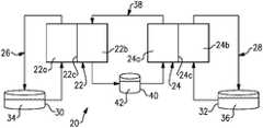
- FIG. 1schematically illustrates an RFB 20 .
- the RFB 20includes a first cell 22 and a second cell 24 .
- the cells 22 and 24are of nominally identical constriction.
- the cells 22 and 24include, respectively, first electrodes 22 a and 24 a , second electrodes 22 b and 24 b , and separator layers 22 c and 24 c between the electrodes (layer 22 c between electrodes 22 a and 22 b , and layer 24 c between electrodes 24 a and 24 b ).
- the electrodes 22 a , 22 b , 24 a , and 24 bare porous carbon structures, such as carbon paper or felt.
- the separator layersare ion-exchange membranes 22 c and 24 c , which permit selected ions to pass through to complete the redox reactions while electrically isolating the electrodes.
- a first circulation loop 26is fluidly connected with the first electrode 22 a of the first cell 22
- a second circulation loop 28is fluidly connected with the second electrode 24 b of the second cell 24 .
- a “loop”refers to a continuous, closed circuit fluid passage.
- the first circulation loop 26 and the second circulation loop 28may include respective electrolyte storage tanks 30 and 32 .
- a polysulfide electrolyte solution 34is contained in the first recirculation loop 26 (e.g., in the tank 30 ), and an iron electrolyte solution 36 is contained in the second circulation loop 28 (i.e., in the tank 32 ).
- the polysulfide electrolyte solution 34has a pH 11.5 or greater, and the iron electrolyte solution has a pH 3 or less.
- the polysulfide in the polysulfide electrolyte solution 34generally refers to salts of sulfur in a basic pH solution.
- the saltis sodium salt with the formula Na 2 S x , where x is 2 to 5, in sodium hydroxide.
- the polysulfide electrolyte solution 34may be 2M Na 2 S x in 1M sodium hydroxide.
- the iron in the iron electrolyte solution 36generally refers to iron salts in an acidic solution.
- the iron electrolyte solution 36may be 1M FeCl x in 1M NaCl and 0.3M HCl.
- the RFB 20further includes a third circulation loop 38 fluidly connected with the second electrode 22 b of the first cell 22 and the first electrode 24 a of the second cell 24 .
- the third circulation loop 38may include an electrolyte storage tank 40 .
- the third circulation loop 38contains an intermediator electrolyte solution 42 (i.e., in the tank 42 ) that participates in reactions in both cells 22 and 24 .
- the intermediator electrolyte solution 42has a pH 12 or greater.
- the intermediator electrolyte solution 42includes at least one of quinoxaline, anthraquinone, or benzoquinone.
- the intermediator electrolyte solution 42includes at least one of 1,2-benzoquinone-3,5-disulfonic acid, 4,4′-((9,10-anthraquinone-2,6-diyfldioxy)dibutyrate (2,6-DBEAQ), 1,2-DBEAQ, or 1,8-DBEAQ.
- Other functionalized hydroxylated anthraquinonese.g. 2,6-dihydroxyanthraquinone (2,6-DHAQ)
- Other organic-based redox couplesinclude molecules based on viologens, quinoxalines, or alloxazines. Organomettalic reactants may also be used, such as ferrocenes.
- the intermediator electrolyte solutionis 0.4M NaFe(CN) 6 in 1M NaOH and 1M NaCl. In another example, the intermediator electrolyte solution is 0.5M 2,6-DBEAQ in 0.5M NaOH and 0.5M NaCl.
- the polysulfide electrolyte solution 34circulates through the first electrode 22 a of the first cell 22 and the iron electrolyte solution circulates through the second electrode 24 b of the second cell 24 .
- the intermediator electrolyte solution 42circulates through the second electrode 22 b of the first cell 22 and the first electrode 24 a of the second cell 24 .
- the polysulfide electrolyte solution 34 and the intermediator electrolyte solution 42 in the first cell 22 , and the iron electrolyte solution 36 and the intermediator electrolyte solution 42 in the second cell 24are operable to undergo reversible reactions to store input electrical energy upon charging and discharge the stored electrical energy upon discharging.
- the electrical energymay be transmitted to and from the cells 22 and 24 through an electric circuit that is electrically coupled with the electrodes 22 a , 22 b , 24 a , and 24 b.
- the intermediator electrolyte solution 42 in the RFB 20mitigates the incompatibility and enables use of sulfide and iron electrolytes together. For instance, rather than sulfur crossing-over into an iron solution, the sulfur in the RFB 20 crosses-over into the intermediator electrolyte solution 42 . And rather than iron crossing-over into a sulfur solution, the iron in the RFB 20 crosses-over into the intermediator electrolyte solution 42 .
- the intermediator electrolyte solution 42is selected to produce more desirable reactions with the sulfur and the iron such that the sulfur and iron can readily be recovered and returned to their respective solutions 34 and 36 .
- the sulfurcrosses-over from the first electrode 22 a through the ion-exchange layer 22 c and into the intermediator electrolyte solution 42 at the second electrode 22 b , the sulfur precipitates as a solid sulfur product.
- the ironcrosses-over from the second electrode 24 b through the ion-exchange layer 24 c and into the intermediator electrolyte solution 42 at the first electrode 24 a , the iron precipitates as a solid iron product.
- the conditions for the sulfur and the iron to precipitaterequire that the pH of the intermediator electrolyte solution 42 be 12 or greater and that the standard electrode potential be greater than ⁇ 0.3V.
- the sulfurmay react to form hydrogen sulfide gas and the iron may react to form insoluble iron oxide.
- the solid sulfur product and solid iron oxide productcan readily be recovered and incorporated back into, respectively, the polysulfide electrolyte solution 34 and the iron electrolyte solution 36 to maintain RFB performance.
- the selected intermediator electrolyte solution 42has highly reversible kinetics between its reduction and oxidation reactions, has ionic function groups (e.g., OH ⁇ ), and is a large molecule to reduce cross-over of the intermediator. Solubility of the intermediator electrolyte solution 42 is not critical, since the intermediator electrolyte solution 42 maintains a state-of-charge of approximately 50% at all times and only a limited quantity of the intermediator electrolyte is required (i.e., the amount does not determine the total energy capacity of the battery).
- FIG. 2depicts a further example of the RFB 20 .
- the RFB 20additionally includes one or more flush lines 44 .
- the flush lines 44may be used to remove and recover the solid sulfur product and the solid iron product according to an electrolyte-takeover method (ETM) 50 illustrated in FIG. 3 .
- the method 50generally includes steps 52 and 54 .
- the intermediator electrolyte solution 42is emptied from the second electrode 22 b of the first cell and/or the first electrode 24 a of the second cell 24 .
- the polysulfide electrolyte solution 34is circulated via the flush line 44 through the second electrode 22 b of the first cell and/or the iron electrolyte solution 36 is circulated via the flush line 44 through the first electrode 24 a of the second cell 24 .
- the solid sulfide productis readily soluble in the polysulfide electrolyte solution 34 .
- the polysulfide electrolyte solution 34thus dissolves and removes the solid sulfide product from the second electrode 22 b .
- the solid iron productis readily soluble in the iron electrolyte solution 36 .
- the iron electrolyte solution 36thus dissolves and removes the solid iron product from the first electrode 24 b.
- the polysulfide electrolyte solution 34is then transferred back into the first loop 26 and the iron electrolyte solution 36 is transferred back into the second loop 28 .
- the intermediator electrolyte solution 42can then resume circulation through the cells 22 and 24 to charge or discharge the RFB 20 .
- FIGS. 4 and 5depict further examples of the RFB 20 .
- the RFB 20additionally includes a bypass line 56 and a third cell 58 in the bypass line 56 .
- the bypass line 56 and the third cell 58are in the first loop 26
- the bypass line 56 and the third cell 58are in the second loop 28 .
- the bypass line 56 and the third cell 58may be used according to a method 60 in FIG. 6 to maintain the pH of the polysulfide electrolyte solution 34 to be pH 11.5 or greater or the pH of the iron electrolyte solution 36 to be pH 3 or less.
- the third cell 58is used to electrolyze the polysulfide electrolyte solution 34 ( FIG. 4 ) or the iron electrolyte solution 36 ( FIG. 5 ).
- the third cell 58is an electrolyzer cell that uses input electrical power to drive an electrolysis reaction of the polysulfide electrolyte solution 34 to generate hydrogen gas or the iron electrolyte solution 36 to generate oxygen gas.
- the respective net reactionsare as follows. 2H 2 O+2Na 2 S 2 ⁇ Na 2 S 4 +2NaOH+H 2 (g) (polysulfide electrolyte solution) 2H 2 O+4FeCl 3 ⁇ 4FeCl 2 +4HCl+O 2 (g) (iron electrolyte solution)
- the hydrogencan be introduced into the iron electrolyte solution 36 to adjust the pH of the iron electrolyte solution 36 and/or the oxygen gas can be introduced into the polysulfide electrolyte solution 34 to adjust the pH of the polysulfide electrolyte solution 34 .
- the introducing of the hydrogen gasinvolves sparging (bubbling) the hydrogen gas through iron electrolyte solution 36 , such as in the tank 32 as shown at 66 ( FIG. 4 ).
- the hydrogenreacts with the iron electrolyte solution 36 to lower the pH.
- the introducing of the oxygen gasinvolves sparging (bubbling) the oxygen gas through polysulfide electrolyte solution 34 , such as in the tank 30 as shown at 68 ( FIG. 5 ).
- the oxygenreacts with the polysulfide electrolyte solution 34 to increase the pH.
- the third cell 58may be connected by a bleed line 70 to either the second loop 28 ( FIG. 4 ) or the first loop ( FIG. 5 ).
- Additional species that are attractive for use in RFBs due to low costare permanganate and sulfur.
- manganate species that cross-over into the low potential sulfur electrolytereduces to form insoluble manganate hydroxide Mn(OH) 2 and sulfur that crosses-over into the manganate electrolyte oxidizes to form solid sulfur metal.
- the loss of sulfur and manganate species, and clogging from the insoluble sulfur and manganate specieswill render the RFB inoperable or, at the least, reduce round-trip efficiency to unfeasible levels for use as an RFB.
- the disclosed RFB that utilizes manganate and sulfurdoes not necessarily require an intermediator electrolyte; however, it may employ similar recovery strategies as described above to mitigate the issues resulting from crossover in the RFB.
- crossover results in solid depositsenables the S and Mn to be separated and returned to their original electrolyte.
- the ETM method 50 described abovefor the Fe and S system
- the membranethen exposing both electrodes to the same electrolyte should enable dissolution and recovery.
- This recovery mechanismis expected to be quick (i.e., ⁇ 1 hour) and, if needed, it can be conducted at elevated temperatures to accelerate the process. The end result is that electrolyte balance is maintained.
- FIG. 7shows another example RFB 120 .
- the RFB 120 in this exampledoes not include a third circulation loop and only includes a single, common cell 122 or stack of common cells.
- the cell 122includes a first electrode 122 a , a second electrode 122 b , and separator layers 122 c between the electrodes 122 a and 122 b .
- like reference numeralsdesignate like elements where appropriate and reference numerals with the addition of one-hundred or multiples thereof designate modified elements that are understood to incorporate the same features and benefits of the corresponding elements.
- the first circulation loop 26is fluidly connected with the first electrode 122 a of the cell 122
- a second circulation loop 28is fluidly connected with the second electrode 122 b of the cell 122
- the polysulfide electrolyte solution 34is contained in the first recirculation loop 26 (e.g., in the tank 30 )
- a manganate electrolyte solution 136is contained in the second circulation loop 28 (i.e., in the tank 32 ).
- the polysulfide electrolyte solution 34is pumped through the second electrode 122 b (after draining), which reduces, dissolves, and recaptures any solid 5°.
- the polysulfide electrolyte solution 34is passed in a first direction 80 a and through a bi-directional filter 80 that is in a first auxiliary loop 82 a to capture any residual Mn that precipitates.
- the manganate electrolyte solution 136is pumped through first electrode 122 a (after draining), which oxidizes and dissolves any Mn(OH) 2 precipitate.
- the manganate electrolyte solution 136is passed in a second direction 80 b through the same bi-directional filter 80 but as a part of a second auxiliary loop 82 b to capture any residual S that precipitates.
- the bi-directional filter 80enables recapture of precipitated species that are filtered out to be recaptured in the polysulfide electrolyte solution 34 and the manganate electrolyte solution 136 .
- O 2can be consumed by allowing it to react with the negolyte by connecting the gas space above the posolyte and negolyte reservoirs (this gas space shall be maintained as a N 2 blanket to prevent discharge of the anolyte): O 2 +2H 2 O+4Na 2 S 2 ⁇ 2Na 2 S 4 +4NaOH
Landscapes
- Chemical & Material Sciences (AREA)
- Chemical Kinetics & Catalysis (AREA)
- Electrochemistry (AREA)
- General Chemical & Material Sciences (AREA)
- Life Sciences & Earth Sciences (AREA)
- Engineering & Computer Science (AREA)
- Manufacturing & Machinery (AREA)
- Sustainable Development (AREA)
- Sustainable Energy (AREA)
- Fuel Cell (AREA)
Abstract
Description
2Na2S2↔Na2S4+2Na++2e′;Eo=−0.45 vs SHE
[Fe(CN)6]3-+e′↔[Fe(CN)6]4-;Eo=+0.36 vs SHE
[Fe(CN)6]4-↔[Fe(CN)6]3-+e′;Eo=+0.36 vs SHE
2FeCl3+2Na++2e′↔2FeCl2+2NaCl;Eo=+0.771 vs SHE
2Na2S2+2FeCl3→Na2S4+2FeCl2+2NaCl
2H2O+2Na2S2→Na2S4+2NaOH+H2(g) (polysulfide electrolyte solution)
2H2O+4FeCl3→4FeCl2+4HCl+O2(g) (iron electrolyte solution)
2Na2S2↔Na2S4+2Na++2e− Negative:
2NaMnO4+2Na++2e−↔2Na2MnO4 Positive:
2Na2S2+2NaMnO4↔Na2S4+2Na2MnO4 Net cell:
4NaMnO4+4NaOH→4Na2MnO4+2H2O+O2
O2+2H2O+4Na2S2↔2Na2S4+4NaOH
Claims (11)
Priority Applications (5)
| Application Number | Priority Date | Filing Date | Title |
|---|---|---|---|
| US16/052,727US11056698B2 (en) | 2018-08-02 | 2018-08-02 | Redox flow battery with electrolyte balancing and compatibility enabling features |
| EP19188587.0AEP3605696B1 (en) | 2018-08-02 | 2019-07-26 | Redox flow battery with electrolyte balancing and compatibility enabling features |
| DK19188587.0TDK3605696T3 (en) | 2018-08-02 | 2019-07-26 | REDOX FLOW BATTERY WITH ELECTROLYTLE BALANCE AND COMPATIBILITY ACTIVATION PROPERTIES |
| JP2019140397AJP7201552B2 (en) | 2018-08-02 | 2019-07-31 | REDOX FLOW BATTERY AND METHOD FOR REDOX FLOW BATTERY |
| US17/361,385US11637298B2 (en) | 2018-08-02 | 2021-06-29 | Redox flow battery with electrolyte balancing and compatibility enabling features |
Applications Claiming Priority (1)
| Application Number | Priority Date | Filing Date | Title |
|---|---|---|---|
| US16/052,727US11056698B2 (en) | 2018-08-02 | 2018-08-02 | Redox flow battery with electrolyte balancing and compatibility enabling features |
Related Child Applications (1)
| Application Number | Title | Priority Date | Filing Date |
|---|---|---|---|
| US17/361,385DivisionUS11637298B2 (en) | 2018-08-02 | 2021-06-29 | Redox flow battery with electrolyte balancing and compatibility enabling features |
Publications (2)
| Publication Number | Publication Date |
|---|---|
| US20200044267A1 US20200044267A1 (en) | 2020-02-06 |
| US11056698B2true US11056698B2 (en) | 2021-07-06 |
Family
ID=67439077
Family Applications (2)
| Application Number | Title | Priority Date | Filing Date |
|---|---|---|---|
| US16/052,727Active2039-02-09US11056698B2 (en) | 2018-08-02 | 2018-08-02 | Redox flow battery with electrolyte balancing and compatibility enabling features |
| US17/361,385Active2038-12-01US11637298B2 (en) | 2018-08-02 | 2021-06-29 | Redox flow battery with electrolyte balancing and compatibility enabling features |
Family Applications After (1)
| Application Number | Title | Priority Date | Filing Date |
|---|---|---|---|
| US17/361,385Active2038-12-01US11637298B2 (en) | 2018-08-02 | 2021-06-29 | Redox flow battery with electrolyte balancing and compatibility enabling features |
Country Status (4)
| Country | Link |
|---|---|
| US (2) | US11056698B2 (en) |
| EP (1) | EP3605696B1 (en) |
| JP (1) | JP7201552B2 (en) |
| DK (1) | DK3605696T3 (en) |
Families Citing this family (14)
| Publication number | Priority date | Publication date | Assignee | Title |
|---|---|---|---|---|
| CN120049075A (en) | 2018-07-27 | 2025-05-27 | 福恩能源公司 | Negative electrode for electrochemical cells |
| CN111261917B (en)* | 2018-11-30 | 2021-06-22 | 中国科学院大连化学物理研究所 | Application of soluble manganate as additive in positive electrolyte of zinc-nickel flow battery |
| US12294086B2 (en) | 2019-07-26 | 2025-05-06 | Form Energy, Inc. | Low cost metal electrodes |
| US11637341B1 (en)* | 2020-02-14 | 2023-04-25 | Massachusetts Institute Of Technology | Multi-phase electrochemical cells and related systems and methods |
| CN114105893B (en)* | 2020-08-28 | 2024-10-18 | 西湖大学 | Electrolyte based on amino acid derivative and application of electrolyte in flow battery |
| KR102486285B1 (en)* | 2020-10-08 | 2023-01-10 | 탑에코에너지주식회사 | Redox flow battery |
| US11271226B1 (en)* | 2020-12-11 | 2022-03-08 | Raytheon Technologies Corporation | Redox flow battery with improved efficiency |
| US12288912B2 (en)* | 2020-12-31 | 2025-04-29 | Uop Llc | Redox flow battery with a balancing cell |
| US11664518B2 (en)* | 2021-05-21 | 2023-05-30 | Raytheon Technologies Corporation | Alkaline manganese redox flow battery with inhibitor |
| US12206144B2 (en)* | 2022-03-25 | 2025-01-21 | The Chinese University Of Hong Kong | Polysulfide-based aqueous redox flow battery with soluble organic catalyst |
| AU2022458327B2 (en) | 2022-05-09 | 2025-06-12 | Lockheed Martin Energy, Llc | Flow battery with a dynamic fluidic network |
| CN115000480B (en)* | 2022-07-28 | 2024-10-22 | 长沙理工大学 | High-energy-density alkaline iron-sulfur flow battery and preparation method thereof |
| CN115275293A (en)* | 2022-08-12 | 2022-11-01 | 北京九州恒盛电力科技有限公司 | Flow battery and control method thereof |
| CN118412509B (en)* | 2024-05-27 | 2025-02-07 | 安徽恒焺储能科技有限公司 | Acid-base amphoteric iron-sulfur hybrid flow battery and preparation method thereof |
Citations (205)
| Publication number | Priority date | Publication date | Assignee | Title |
|---|---|---|---|---|
| US3152013A (en) | 1960-05-17 | 1964-10-06 | Ionics | Fuel cell |
| US3245836A (en) | 1960-02-23 | 1966-04-12 | Gen Motors Corp | Regenerative battery |
| GB1375437A (en) | 1971-02-25 | 1974-11-27 | ||
| US4053684A (en) | 1972-10-10 | 1977-10-11 | Gel, Inc. | Method of operating a fuel cell |
| US4124478A (en) | 1977-02-07 | 1978-11-07 | Tsien Hsue C | Thin sheet apparatus and a fluid flow device |
| JPS5419228A (en) | 1977-07-14 | 1979-02-13 | Matsushita Electric Works Ltd | Manufacturing of solar heat collector |
| GB2010574A (en) | 1977-12-19 | 1979-06-27 | Lockheed Missiles Space | Electrically rechargeable battery |
| US4407902A (en) | 1980-12-08 | 1983-10-04 | Ford Motor Company | Chemically regenerable redox fuel cell and method of operating the same |
| JPS6047373B2 (en) | 1980-03-05 | 1985-10-21 | グロブ・アンド・カムパニ−・アクチエンゲゼルシヤフト | Held |
| JPS61173468A (en) | 1985-01-28 | 1986-08-05 | Mitsui Eng & Shipbuild Co Ltd | electrolytic or battery equipment |
| JPS63213261A (en) | 1987-02-27 | 1988-09-06 | Nkk Corp | Electrolyte flow type battery |
| US4786567A (en) | 1986-02-11 | 1988-11-22 | Unisearch Limited | All-vanadium redox battery |
| JPH01146267A (en) | 1987-12-03 | 1989-06-08 | Chiyoda Corp | Operation of redox-flow cell |
| WO1989005528A1 (en) | 1987-12-10 | 1989-06-15 | Unisearch Limited | Vanadium charging cell and vanadium dual battery system |
| WO1989005363A1 (en) | 1987-12-10 | 1989-06-15 | Unisearch Limited | Vanadium compound dissolution processes |
| WO1990003666A1 (en) | 1988-09-23 | 1990-04-05 | Unisearch Limited | State of charge of redox cell |
| JPH02148659A (en) | 1988-11-30 | 1990-06-07 | Toyobo Co Ltd | redox flow battery |
| JPH02195657A (en) | 1989-01-23 | 1990-08-02 | Sumitomo Electric Ind Ltd | Electrolyte circulation type secondary battery |
| JPH04223049A (en) | 1990-12-26 | 1992-08-12 | Toyota Motor Corp | Zinc bromine cell |
| EP0517217A1 (en) | 1991-06-06 | 1992-12-09 | Director-General Of The Agency Of Industrial Science And Technology | Redox battery |
| US5188911A (en) | 1991-02-25 | 1993-02-23 | Magnavox Electronic Systems Company | Tapered manifold for batteries requiring forced electrolyte flow |
| US5270132A (en) | 1991-12-26 | 1993-12-14 | International Fuel Cells Corporation | Minimized corrosion fuel cell device and a method of making the same |
| US5298341A (en) | 1992-08-20 | 1994-03-29 | Cerramatec, Inc. | Multiple stack ion conducting devices |
| WO1994009525A1 (en) | 1992-10-14 | 1994-04-28 | National Power Plc | Electrochemical energy storage and power delivery process utilizing iron-sulfur couple |
| WO1994009526A1 (en) | 1992-10-14 | 1994-04-28 | National Power Plc | Electrochemical apparatus for energy storage and/or power delivery comprising multi-compartment cells |
| JPH07192748A (en) | 1993-12-24 | 1995-07-28 | Agency Of Ind Science & Technol | Electrolyte flow-through type cell |
| US5612148A (en)* | 1994-04-13 | 1997-03-18 | National Power Plc | Process for energy storage and/or power delivery with means for restoring electrolyte balance |
| JPH09101286A (en) | 1995-10-04 | 1997-04-15 | Kashimakita Kyodo Hatsuden Kk | Method and instrument for measuring atomicity and concentration of vanadium ion of electrolyte for vanadium redox flow battery |
| US5648184A (en) | 1995-04-13 | 1997-07-15 | Toyo Boseki Kabushiki Kaisha | Electrode material for flow-through type electrolytic cell, wherein the electrode comprises carbonaceous material having at least one groove |
| JPH1040944A (en) | 1996-07-24 | 1998-02-13 | Sumitomo Electric Ind Ltd | Redox flow battery and method of operating the same |
| US5830603A (en) | 1993-09-03 | 1998-11-03 | Sumitomo Electric Industries, Ltd. | Separator film for a storage battery |
| US5851694A (en) | 1996-06-19 | 1998-12-22 | Kashima-Kita Electric Power Corporation | Redox flow type battery |
| US6007933A (en) | 1998-04-27 | 1999-12-28 | Plug Power, L.L.C. | Fuel cell assembly unit for promoting fluid service and electrical conductivity |
| JP2000030721A (en) | 1998-07-10 | 2000-01-28 | Sumitomo Electric Ind Ltd | Method for regenerating electrolyte solution for all vanadium redox flow batteries |
| US20010028977A1 (en) | 1995-05-03 | 2001-10-11 | Michael Kazacos | High energy density vanadium electrolyte solutions, methods of preparation thereof and all-vanadium redox cells and batteries containing high energy vanadium electrolyte solutions |
| US6309532B1 (en) | 1994-05-20 | 2001-10-30 | Regents Of The University Of California | Method and apparatus for capacitive deionization and electrochemical purification and regeneration of electrodes |
| US20020014880A1 (en) | 2000-07-21 | 2002-02-07 | Mcandrews Joseph M. | Automatic battery charging system (ABC) |
| WO2002015317A1 (en) | 2000-08-16 | 2002-02-21 | Squirrel Holdings Ltd. | Vanadium electrolyte preparation using asymmetric vanadium reduction cells and use of an asymmetric vanadium reduction cell for rebalancing the state of charge of the electrolytes of an operating vanadium redox battery |
| US6355373B1 (en) | 1996-06-21 | 2002-03-12 | Zoxy Energy Systems Ag | Battery |
| US20020064702A1 (en) | 1998-12-30 | 2002-05-30 | Gibb Peter R. | Fuel cell fluid flow field plate and methods of making fuel cell flow field plates |
| JP2002175822A (en) | 2000-12-07 | 2002-06-21 | Sumitomo Electric Ind Ltd | Redox flow battery and method of operating the same |
| US20020086200A1 (en) | 2000-12-29 | 2002-07-04 | Margiott Paul R. | Hybrid fuel cell reactant flow fields |
| US6416899B1 (en) | 1998-11-06 | 2002-07-09 | Honda Giken Kogyo Kabushiki Kaisha | Fuel cell stack |
| GB2372143A (en) | 2001-02-12 | 2002-08-14 | Morgan Crucible Co | Flow field plate geometries for a fuel cell,including for a polymer electrolyt e fuel cell |
| US20020192513A1 (en) | 2001-05-31 | 2002-12-19 | Kevin Colbow | Method of improving the performance of a direct feed fuel cell |
| US6522919B1 (en) | 1995-08-29 | 2003-02-18 | Vyteris, Inc. | Iontophoretic drug delivery device having high-efficiency DC-to-DC energy conversion circuit |
| JP2003079070A (en) | 2000-09-28 | 2003-03-14 | Kansai Electric Power Co Inc:The | Electric power storage system |
| US20030087156A1 (en) | 2001-04-12 | 2003-05-08 | Squirrel Holdings Ltd. | Porous mat electrodes for electrochemical reactor having electrolyte solution distribution channels |
| WO2003041199A2 (en) | 2001-11-07 | 2003-05-15 | Intelligent Energy Limited | Fuel cell fluid flow field plates |
| JP2003157883A (en) | 2001-11-21 | 2003-05-30 | Sumitomo Electric Ind Ltd | Method for regenerating electrolyte for vanadium redox battery |
| WO2003050900A1 (en) | 2001-12-11 | 2003-06-19 | Powerzyme, Inc. | Electrochemical device with adjustable-area electrodes using a hydrogen peroxide catholyte |
| US20030129468A1 (en) | 2002-01-04 | 2003-07-10 | Honeywell International, Inc. | Gas block mechanism for water removal in fuel cells |
| US20030134163A1 (en) | 2002-01-14 | 2003-07-17 | The Board Of Trustees Of University Of Illinois. | Electrochemical cells comprising laminar flow induced dynamic conducting interfaces, electronic devices comprising such cells, and methods employing same |
| JP2003217607A (en) | 2002-01-21 | 2003-07-31 | Mitsubishi Materials Corp | Separator, method for manufacturing the separator, and solid high polymer fuel cell |
| US6628085B2 (en) | 2001-01-17 | 2003-09-30 | Tai-Her Yang | Limit voltage circuit using light emitting diodes as thermal-loss reducing impedances, especially for matching a saturation voltage of rechargeable cells during charging |
| JP2003303611A (en) | 2002-04-10 | 2003-10-24 | Sumitomo Electric Ind Ltd | How to operate a redox flow battery |
| GB2390738A (en) | 2002-07-09 | 2004-01-14 | Intelligent Energy Ltd | Fuel cell direct water injection |
| US6692862B1 (en) | 2000-03-31 | 2004-02-17 | Squirrel Holdings Ltd. | Redox flow battery and method of operating it |
| US20040070370A1 (en) | 2001-08-03 | 2004-04-15 | Katsuji Emura | Method for operating power source system and power source system comprising secondary battery |
| US20040086763A1 (en) | 2002-10-31 | 2004-05-06 | Stephen Paddison | Hydrophilic side-chain polymer electrolyte membranes |
| US20040126642A1 (en) | 2002-09-12 | 2004-07-01 | Smedley Kent I. | Methods and devices for controlling flow and particle fluidization in a fuel cell |
| US20040151960A1 (en) | 2003-01-31 | 2004-08-05 | Rock Jeffrey Allan | Flow restrictors in fuel cell flow-field |
| WO2004071967A1 (en) | 2003-02-12 | 2004-08-26 | The C & M Group, Llc | Mediated electrochemical oxidation of animal waste materials |
| WO2004079849A1 (en) | 2003-03-04 | 2004-09-16 | Squirrel Holdings Ltd. | Multi voltage tap redox flow battery composed of stacked cell modules of adjustable cell area |
| US20040191623A1 (en) | 2001-06-07 | 2004-09-30 | Michiru Kubata | Electrolyte for redox flow battery, and redox flow battery |
| US20040202915A1 (en) | 2001-06-12 | 2004-10-14 | Hiroyuki Nakaishi | Cell frame for redox-flow cell and redox-flow cell |
| US20040224192A1 (en) | 2003-05-06 | 2004-11-11 | Ballard Power Systems Inc. | Method and apparatus for improving the performance of a fuel cell electric power system |
| US20040241544A1 (en) | 2001-06-12 | 2004-12-02 | Hiroyuki Nakaishi | Cell stack for flow cell |
| US6828055B2 (en) | 2001-07-27 | 2004-12-07 | Hewlett-Packard Development Company, L.P. | Bipolar plates and end plates for fuel cells and methods for making the same |
| US20040256247A1 (en) | 2001-10-22 | 2004-12-23 | Carson Roger W. | Mediated electrochemical oxidation of organic waste materials |
| US6841294B1 (en) | 1999-07-02 | 2005-01-11 | Regenesys Technologies Limited | Electrolyte rebalancing system |
| US20050074649A1 (en) | 2003-10-07 | 2005-04-07 | Tommy Skiba | Fuel cell voltage control |
| US20050074653A1 (en) | 2001-06-28 | 2005-04-07 | Squirrel Holdings Ltd. | Redox cell with non-selective permionic separator |
| US20050106450A1 (en) | 2003-11-14 | 2005-05-19 | Castro Emory S.D. | Structures for gas diffusion materials and methods for their fabrication |
| US20050136301A1 (en) | 2003-12-19 | 2005-06-23 | Ballard Power Systems Inc. | Monitoring fuel cells using RFID devices |
| WO2005057707A1 (en) | 2003-12-12 | 2005-06-23 | Lg Electronics Inc. | Bipolar plate of fuel cell |
| US20050158614A1 (en) | 2004-01-15 | 2005-07-21 | Hennessy Timothy D.J. | System and method for optimizing efficiency and power output from a vanadium redox battery energy storage system |
| JP2005228645A (en) | 2004-02-13 | 2005-08-25 | Sumitomo Electric Ind Ltd | Retaining structure of redox flow battery cell, battery, and electrode |
| US20050244703A1 (en) | 2002-04-23 | 2005-11-03 | Paul Osenar | Membrane based electrochemical cell stacks |
| US20050260473A1 (en) | 2004-05-21 | 2005-11-24 | Sarnoff Corporation | Electrical power source designs and components |
| US20060003210A1 (en) | 2004-05-22 | 2006-01-05 | David Ofer | Solid polymer electrolyte membranes |
| KR20060016399A (en) | 2004-08-17 | 2006-02-22 | 현대모비스 주식회사 | Separation plate of fuel cell |
| WO2006026585A2 (en) | 2004-08-30 | 2006-03-09 | Toyota Technical Center Usa, Inc. | Improvement i cycling stability of li-ion battery with molten salt electrolyte |
| US20060108214A1 (en) | 2004-11-19 | 2006-05-25 | Steven Amendola | Load leveling and electrolysis system |
| JP2006156029A (en) | 2004-11-26 | 2006-06-15 | Kansai Electric Power Co Inc:The | Carbon electrode material for vanadium redox flow battery |
| US20060138996A1 (en) | 2004-12-23 | 2006-06-29 | Graham David R | Modular portable battery charging system using hydrogen fuel cells |
| US20060183016A1 (en) | 2003-04-14 | 2006-08-17 | Michael Kazacos | Novel vanadium halide redox flow battery |
| US7105245B2 (en) | 2002-07-03 | 2006-09-12 | Neah Power Systems, Inc. | Fluid cell system reactant supply and effluent storage cartridges |
| CN1845368A (en) | 2006-03-10 | 2006-10-11 | 清华大学深圳研究生院 | Current collection plate for all vanadium redox flow battery |
| JP2006313691A (en) | 2005-05-09 | 2006-11-16 | Sumitomo Electric Ind Ltd | Redox flow battery system |
| WO2006135958A1 (en) | 2005-06-20 | 2006-12-28 | V-Fuel Pty Ltd | Improved perfluorinated membranes and improved electrolytes for redox cells and batteries |
| US7199550B2 (en) | 2001-05-01 | 2007-04-03 | Sumitomo Electric Industries, Ltd. | Method of operating a secondary battery system having first and second tanks for reserving electrolytes |
| JP2007188729A (en) | 2006-01-12 | 2007-07-26 | Sumitomo Electric Ind Ltd | Regeneration method of vanadium redox flow battery |
| US7250229B2 (en) | 2001-01-25 | 2007-07-31 | Utc Power Corporation | Procedure for starting up a fuel cell system having an anode exhaust recycle loop |
| US20070178359A1 (en) | 2006-01-27 | 2007-08-02 | Samsung Sdi Co., Ltd. | Bipolar plate for fuel cell |
| WO2007086828A2 (en) | 2005-12-28 | 2007-08-02 | Utc Power Corporation | Fuel cell flow field channel with partially closed end |
| US20080115930A1 (en) | 2006-11-22 | 2008-05-22 | Strategic Resource Optimization, Inc. | Electrolytic system and method for enhanced release and deposition of sub-surface and surface components |
| JP2008166164A (en) | 2006-12-28 | 2008-07-17 | Toyota Motor Corp | FUEL CELL SYSTEM AND CONTROL METHOD FOR FUEL CELL SYSTEM |
| US7410712B2 (en) | 2000-12-20 | 2008-08-12 | Utc Power Corporation | Procedure for starting up a fuel cell system using a fuel purge |
| US20080193828A1 (en) | 2007-02-12 | 2008-08-14 | Saroj Kumar Sahu | Apparatus and Methods of Determination of State of Charge in a Redox Flow Battery |
| US20080274393A1 (en) | 2007-04-17 | 2008-11-06 | Markoski Larry J | Hydrogel barrier for fuel cells |
| WO2008148148A1 (en) | 2007-06-07 | 2008-12-11 | V-Fuel Pty Ltd | Efficient energy storage systems using vanadium redox batteries for electricity trading, fossil fuel reduction and electricity power cost savings for consumers |
| CN101325252A (en) | 2007-06-15 | 2008-12-17 | 清华大学 | A bipolar plate for a flow battery |
| WO2009017150A1 (en) | 2007-08-02 | 2009-02-05 | Sony Corporation | Fuel cell stack system, channel structure, fuel cell, electrode, and electronic device |
| US20090071841A1 (en) | 2005-06-16 | 2009-03-19 | Boston University | Waste to hydrogen conversion process and related apparatus |
| US20090092882A1 (en) | 2007-10-09 | 2009-04-09 | University Of Victoria Innovation And Development Corporation | Fuel cell with flow-through porous electrodes |
| US7527886B2 (en) | 2003-12-26 | 2009-05-05 | Utc Power Corporation | Start up of cascaded fuel cell stack |
| US20090136789A1 (en) | 2007-10-31 | 2009-05-28 | Pien Shyhing M | Integrated Flow Field (IFF) Structure |
| JP2009283425A (en) | 2008-05-19 | 2009-12-03 | Yamabishi Ind Co Ltd | Oxidation reduction-type electricity storage device using circulatory regenerated pure water as electrolyte solution |
| US20090311567A1 (en) | 2008-06-16 | 2009-12-17 | Polyplus Battery Company | Hydrogels for aqueous lithium/air battery cells |
| US20100003545A1 (en) | 2008-07-07 | 2010-01-07 | Enervault Corporation | Redox Flow Battery System for Distributed Energy Storage |
| US20100003586A1 (en) | 2008-07-01 | 2010-01-07 | Deeya Energy, Inc. A California C-Corp | Redox flow cell |
| US20100047671A1 (en) | 2008-06-12 | 2010-02-25 | Massachusetts Institute Of Technology | High energy density redox flow device |
| US20100092813A1 (en) | 2008-10-10 | 2010-04-15 | Saroj Kumar Sahu | Thermal Control of a Flow Cell Battery |
| KR20100040606A (en) | 2008-10-10 | 2010-04-20 | 한국과학기술연구원 | Electrode for soluble lead acid redox flow battery and soluble lead acid redox flow battery using the same |
| US20100104904A1 (en) | 2007-04-26 | 2010-04-29 | Vineet Rao | System For Generating Electrical Energy Comprising An Electrochemical Reformer And A Fuel Cell |
| US20100136455A1 (en) | 2008-10-10 | 2010-06-03 | Rick Winter | Common Module Stack Component Design |
| US20100143781A1 (en)* | 2008-12-05 | 2010-06-10 | Majid Keshavarz | Methods for the preparation and purification of electrolytes for redox flow batteries |
| WO2010067453A1 (en) | 2008-12-12 | 2010-06-17 | トヨタ自動車株式会社 | Fuel cell |
| US20100178533A1 (en) | 2007-07-02 | 2010-07-15 | Cellstrom Gmbh | Redox flow battery |
| US7790303B2 (en) | 2003-09-23 | 2010-09-07 | Utc Power Corporation | Storage of fuel cell energy during startup and shutdown or other power transitions |
| WO2010107429A1 (en) | 2009-03-18 | 2010-09-23 | Utc Power Corporation | Fuel cell for moisture management at gas inlets |
| JP2010244972A (en) | 2009-04-09 | 2010-10-28 | Sharp Corp | Redox flow battery |
| US7855020B1 (en) | 2003-08-06 | 2010-12-21 | Utc Power Corporation | Hydrogen passivation shut down system for a fuel cell power plant |
| US7855015B1 (en) | 2003-04-17 | 2010-12-21 | University Of South Florida | Aluminum and solid alkali peroxide galvanic cell |
| US20100323264A1 (en) | 2009-04-06 | 2010-12-23 | A123 Systems, Inc. | Fuel system using redox flow battery |
| US20100330451A1 (en) | 2007-06-28 | 2010-12-30 | Kazuma Shinozaki | Electrode catalyst substrate and method for producing the same, and polymer electrolyte fuel cell |
| US20110008706A1 (en) | 2008-04-22 | 2011-01-13 | Cipollini Ned E | Polymer coating of pem fuel cell catalyst layers |
| US20110006737A1 (en) | 2009-07-10 | 2011-01-13 | Narayana Prakash Saligram | Battery charging method and apparatus |
| US20110020732A1 (en) | 2008-04-18 | 2011-01-27 | Robert Mason Darling | Fuel cell component with interdigitated flow fields |
| US20110074357A1 (en) | 2009-05-28 | 2011-03-31 | Parakulam Gopalakrishnan R | Control system for a flow cell battery |
| US20110087389A1 (en) | 2009-10-09 | 2011-04-14 | Gm Global Technology Operations, Inc. | Standby mode for optimization of efficiency and durability of a fuel cell vehicle application |
| US20110086247A1 (en) | 2009-05-28 | 2011-04-14 | Majid Keshavarz | Redox flow cell rebalancing |
| US20110117975A1 (en) | 2009-11-17 | 2011-05-19 | Etymotic Research, Inc. | Two-Way Communication Device |
| US20110119005A1 (en) | 2008-07-11 | 2011-05-19 | Mitsumi Electric Co., Ltd. | Battery-state monitoring apparatus |
| US20110143249A1 (en) | 2008-08-06 | 2011-06-16 | Toyota Jidosha Kabushiki Kaisha | Fuel cell system and method of controlling the fuel cell system |
| WO2011075135A1 (en) | 2009-12-18 | 2011-06-23 | United Technologies Corporation | Flow battery with interdigitated flow field |
| US20110189520A1 (en) | 2008-06-12 | 2011-08-04 | 24M Technologies, Inc. | High energy density redox flow device |
| US20110223450A1 (en) | 2008-07-07 | 2011-09-15 | Enervault Corporation | Cascade Redox Flow Battery Systems |
| US20110223451A1 (en) | 2010-09-08 | 2011-09-15 | Primus Power Corporation | Metal electrode assembly for flow batteries |
| US20110248653A1 (en) | 2010-04-07 | 2011-10-13 | Black & Decker Inc. | Controlled power fade for battery powered devices |
| US20110249373A1 (en) | 2008-12-12 | 2011-10-13 | Ionix Power Systems | Active electrolyte electrochemical capacitor |
| US20110269055A1 (en) | 2009-01-08 | 2011-11-03 | Utc Power Corporation | Multiple transition flow field and method |
| US20110274948A1 (en) | 2010-04-09 | 2011-11-10 | Massachusetts Institute Of Technology | Energy transfer using electrochemically isolated fluids |
| US8062801B2 (en) | 2006-08-31 | 2011-11-22 | Utc Power Corporation | Avoiding coolant slump into reactant fields during PEM fuel cell shutdown |
| EP2395584A1 (en) | 2009-02-06 | 2011-12-14 | Golden Energy Fuel Cell Co., Ltd. | Electrode for a flow battery |
| US20120003562A1 (en) | 2009-01-23 | 2012-01-05 | Utc Power Corporation | Fuel cell |
| US20120030886A1 (en) | 2010-05-31 | 2012-02-09 | Hubner Transportation Gmbh | Device for an extendable reception of a ramp |
| CN102354761A (en) | 2011-10-10 | 2012-02-15 | 中国东方电气集团有限公司 | Redox flow cell system and shutdown protection method as well as device thereof |
| US20120045680A1 (en) | 2010-03-12 | 2012-02-23 | Yongrong Dong | Redox flow battery |
| US20120052347A1 (en) | 2010-08-25 | 2012-03-01 | Applied Materials, Inc. | Flow battery systems |
| US8142950B2 (en) | 2003-08-06 | 2012-03-27 | Utc Power Corporation | Hydrogen passivation shut down system for a fuel cell power plant |
| US20120100461A1 (en) | 2009-06-26 | 2012-04-26 | Nissan Motor Co., Ltd. | Hydrophilic porous layer for fuel cells, gas diffusion electrode and manufacturing method thereof, and membrane electrode assembly |
| US20120149573A1 (en) | 2009-09-09 | 2012-06-14 | Kanu Maganbhai Patel | Herbicidal bus-nitrogen-containing oxo and sulfono heterocycles |
| WO2012088442A2 (en) | 2010-12-23 | 2012-06-28 | 24M Technologies, Inc. | Semi-solid filled battery and method of manufacture |
| US20120203392A1 (en) | 2011-02-07 | 2012-08-09 | United Technologies Corporation | Method and system for operating a flow battery system based on energy costs |
| US20120202099A1 (en) | 2011-02-08 | 2012-08-09 | United Technologies Corporation | Flow battery having a low resistance membrane |
| US20120208061A1 (en) | 2011-01-13 | 2012-08-16 | Deeya Energy, Inc. | Flow cell stack |
| US20120220673A1 (en) | 2007-01-26 | 2012-08-30 | The Secretary Of State For Defence | Anion exchange membranes |
| JP2012164530A (en) | 2011-02-07 | 2012-08-30 | Sumitomo Electric Ind Ltd | Electrolyte circulation type battery |
| US20120244406A1 (en)* | 2011-03-25 | 2012-09-27 | Battelle Memorial Institute | Iron-Sulfide Redox Flow Batteries |
| WO2012135473A2 (en) | 2011-03-29 | 2012-10-04 | Enervault Corporation | Monitoring electrolyte concentrations in redox flow battery systems |
| US20120247573A1 (en) | 2009-06-29 | 2012-10-04 | Lomax Jr Franklin D | Method and Manifold for Carrying Reduced Moment Due to Dimensional Change in Pressure Vessel; Removable Insert with Valve Seat; Pressure Assisted Valve Arrangement and Method |
| US20120258345A1 (en) | 2011-02-07 | 2012-10-11 | Rachid Zaffou | Flow battery having electrodes with a plurality of different pore sizes and or different layers |
| WO2012162390A1 (en) | 2011-05-23 | 2012-11-29 | University Of Kentucky Research Foundation | Flow battery and mn/v electrolyte system |
| WO2012160406A1 (en) | 2011-05-26 | 2012-11-29 | Krisada Kampanatsanyakorn | Method of conducting an all vanadium redox flow battery and implementing system |
| US20120308856A1 (en) | 2010-12-08 | 2012-12-06 | Enervault Corporation | Shunt current resistors for flow battery systems |
| US20120306452A1 (en) | 2011-06-02 | 2012-12-06 | Robert Bosch Gmbh | System and method for discharging a high impedance battery |
| US20120321920A1 (en) | 2011-06-14 | 2012-12-20 | Pratt & Whitney Rocketdyne, Inc. | System and method for operating a flow battery system at an elevated temperature |
| US20120326672A1 (en) | 2009-01-16 | 2012-12-27 | Kevin Dennis | Reversible polarity operation and switching method for ZnBr flow battery when connected to common DC bus |
| US20120328910A1 (en) | 2011-06-27 | 2012-12-27 | Primus Power Corporation | Electrolyte Flow Configuration for a Metal-Halogen Flow Battery |
| CN102859775A (en) | 2011-03-25 | 2013-01-02 | 住友电气工业株式会社 | Redox-flow battery and method of operating thereof |
| US20130011704A1 (en) | 2008-07-07 | 2013-01-10 | Enervault Corporation | Redox Flow Battery System with Multiple Independent Stacks |
| US20130022846A1 (en) | 2011-07-19 | 2013-01-24 | Mao-Huang Liu | Electrode structure of vanadium redox flow battery |
| US20130029196A1 (en) | 2011-07-29 | 2013-01-31 | Pratt & Whitney Rocketdyne, Inc. | Flow battery cells arranged between an inlet manifold and an outlet manifold |
| WO2013018383A1 (en) | 2011-08-03 | 2013-02-07 | 日立アプライアンス株式会社 | Air conditioner |
| WO2013027076A1 (en) | 2011-08-23 | 2013-02-28 | Squirrel Holdings Ltd. | "in situ" production of electrolyte solution from vanadium pentoxide for use in a flow redox battery storage system |
| US20130059189A1 (en) | 2010-05-05 | 2013-03-07 | Roger A. Benham | Pressure density differential device |
| CN103000927A (en) | 2012-12-29 | 2013-03-27 | 大连融科储能技术发展有限公司 | Application of small organic molecules as capacity recovery additives for vanadium redox flow batteries |
| US20130084482A1 (en) | 2011-03-29 | 2013-04-04 | Enervault Corporation | Rebalancing electrolytes in redox flow battery systems |
| US20130095362A1 (en) | 2011-10-14 | 2013-04-18 | Deeya Energy, Inc. | Vanadium flow cell |
| WO2013054921A1 (en) | 2011-10-14 | 2013-04-18 | 株式会社ギャラキシー | Vanadium electrolyte, production method therefor, and production device therefor |
| US20130136199A1 (en) | 2010-07-26 | 2013-05-30 | Huawei Technologies Co., Ltd. | Channel estimation method, apparatus and system |
| US20130157087A1 (en) | 2011-12-20 | 2013-06-20 | Arun Pandy | Flow battery system with standby mode |
| US20130157155A1 (en) | 2010-08-16 | 2013-06-20 | Foundation Of Soongsil University-Industry Cooperation | Fuel Cell Including Cathode Electrode Using Iron Redox Couple |
| US20130154364A1 (en) | 2011-12-20 | 2013-06-20 | Jd Holding Inc | Vanadium redox battery energy storage system |
| WO2013095374A2 (en) | 2011-12-20 | 2013-06-27 | United Technologies Corporation | Flow battery with enhanced durability |
| WO2013095378A1 (en) | 2011-12-20 | 2013-06-27 | United Technologies Corporation | Flow battery with mixed flow |
| US20130217851A1 (en) | 2010-08-04 | 2013-08-22 | Michelin Recherche Et Technique S.A. | Triazine polymer that can be used as membrane in a fuel cell |
| WO2013131838A1 (en) | 2012-03-05 | 2013-09-12 | Eos Holding Sa | Redox flow battery for hydrogen generation |
| US20130316268A1 (en) | 2012-05-25 | 2013-11-28 | Samsung Electronics Co., Ltd. | Ion exchange membrane filling composition, method of preparing ion exchange membrane, ion exchange membrane, and redox flow battery |
| US20130316199A1 (en) | 2012-05-25 | 2013-11-28 | Deeya Energy, Inc. | Electrochemical balance in a vanadium flow battery |
| US20140030631A1 (en) | 2012-07-27 | 2014-01-30 | Sun Catalytix Corporation | Electrochemical Energy Storage Systems and Methods Featuring Optimal Membrane Systems |
| US20140127542A1 (en) | 2012-11-05 | 2014-05-08 | Battelle Memorial Institute | Composite Separators and Redox Flow Batteries Based on Porous Separators |
| JP2014098137A (en) | 2012-10-15 | 2014-05-29 | Toray Ind Inc | Block copolymer, method for producing the same, and polymer electrolyte material, polymer electrolyte forming body, and polymer electrolyte fuel cell using block copolymer |
| WO2014088601A1 (en) | 2012-12-09 | 2014-06-12 | United Technologies Corporation | Flow battery with voltage-limiting device |
| WO2014098917A1 (en) | 2012-12-23 | 2014-06-26 | United Technologies Corporation | Carbon electrode and method therefor |
| US20140377687A1 (en) | 2011-12-28 | 2014-12-25 | Asahi Kasei E-Materials Corporation | Redox flow secondary battery and electrolyte membrane for redox flow secondary battery |
| JP2015519718A (en) | 2012-06-15 | 2015-07-09 | ユニバーシティー オブ デラウェア | Multi-membrane, multi-electrolyte redox flow battery design |
| WO2015119272A1 (en) | 2014-02-07 | 2015-08-13 | 東洋紡株式会社 | Ion-exchange membrane for redox battery, complex, and redox battery |
| US9276282B2 (en) | 2009-10-16 | 2016-03-01 | Dalian Rongke Power Co., Ltd. | Aromatic polymer ion exchange membranes, its composite membrane, and its application in acidic electrolyte flow battery |
| US20160126579A1 (en) | 2013-05-16 | 2016-05-05 | United Technologies Corporation | Flow battery with hydrated ion-exchange membrane having maximum water domain cluster sizes |
| US20160233531A1 (en)* | 2013-09-25 | 2016-08-11 | Lockheed Martin Advanced Energy Storage, Llc | Electrolyte balancing strategies for flow batteries |
| JP6047373B2 (en) | 2012-10-31 | 2016-12-21 | アイシン・エィ・ダブリュ株式会社 | Vehicle control apparatus and vehicle control method |
| JP2017517101A (en) | 2014-11-17 | 2017-06-22 | 中国科学院大▲連▼化学物理研究所Dalian Institute Of Chemical Physics,Chinese Academy Of Sciences | Quinone polyhalide flow battery |
- 2018
- 2018-08-02USUS16/052,727patent/US11056698B2/enactiveActive
- 2019
- 2019-07-26EPEP19188587.0Apatent/EP3605696B1/enactiveActive
- 2019-07-26DKDK19188587.0Tpatent/DK3605696T3/enactive
- 2019-07-31JPJP2019140397Apatent/JP7201552B2/enactiveActive
- 2021
- 2021-06-29USUS17/361,385patent/US11637298B2/enactiveActive
Patent Citations (227)
| Publication number | Priority date | Publication date | Assignee | Title |
|---|---|---|---|---|
| US3245836A (en) | 1960-02-23 | 1966-04-12 | Gen Motors Corp | Regenerative battery |
| US3152013A (en) | 1960-05-17 | 1964-10-06 | Ionics | Fuel cell |
| GB1375437A (en) | 1971-02-25 | 1974-11-27 | ||
| US4053684A (en) | 1972-10-10 | 1977-10-11 | Gel, Inc. | Method of operating a fuel cell |
| US4124478A (en) | 1977-02-07 | 1978-11-07 | Tsien Hsue C | Thin sheet apparatus and a fluid flow device |
| JPS5419228A (en) | 1977-07-14 | 1979-02-13 | Matsushita Electric Works Ltd | Manufacturing of solar heat collector |
| GB2010574A (en) | 1977-12-19 | 1979-06-27 | Lockheed Missiles Space | Electrically rechargeable battery |
| US4180623A (en) | 1977-12-19 | 1979-12-25 | Lockheed Missiles & Space Company, Inc. | Electrically rechargeable battery |
| JPS6047373B2 (en) | 1980-03-05 | 1985-10-21 | グロブ・アンド・カムパニ−・アクチエンゲゼルシヤフト | Held |
| US4407902A (en) | 1980-12-08 | 1983-10-04 | Ford Motor Company | Chemically regenerable redox fuel cell and method of operating the same |
| JPS61173468A (en) | 1985-01-28 | 1986-08-05 | Mitsui Eng & Shipbuild Co Ltd | electrolytic or battery equipment |
| US4786567A (en) | 1986-02-11 | 1988-11-22 | Unisearch Limited | All-vanadium redox battery |
| JPS63213261A (en) | 1987-02-27 | 1988-09-06 | Nkk Corp | Electrolyte flow type battery |
| JPH01146267A (en) | 1987-12-03 | 1989-06-08 | Chiyoda Corp | Operation of redox-flow cell |
| WO1989005528A1 (en) | 1987-12-10 | 1989-06-15 | Unisearch Limited | Vanadium charging cell and vanadium dual battery system |
| WO1989005363A1 (en) | 1987-12-10 | 1989-06-15 | Unisearch Limited | Vanadium compound dissolution processes |
| WO1990003666A1 (en) | 1988-09-23 | 1990-04-05 | Unisearch Limited | State of charge of redox cell |
| JPH02148659A (en) | 1988-11-30 | 1990-06-07 | Toyobo Co Ltd | redox flow battery |
| JPH02195657A (en) | 1989-01-23 | 1990-08-02 | Sumitomo Electric Ind Ltd | Electrolyte circulation type secondary battery |
| JPH04223049A (en) | 1990-12-26 | 1992-08-12 | Toyota Motor Corp | Zinc bromine cell |
| US5188911A (en) | 1991-02-25 | 1993-02-23 | Magnavox Electronic Systems Company | Tapered manifold for batteries requiring forced electrolyte flow |
| US5318865A (en) | 1991-06-06 | 1994-06-07 | Director-General, Agency Of Industrial Science And Technology | Redox battery |
| EP0517217A1 (en) | 1991-06-06 | 1992-12-09 | Director-General Of The Agency Of Industrial Science And Technology | Redox battery |
| US5270132A (en) | 1991-12-26 | 1993-12-14 | International Fuel Cells Corporation | Minimized corrosion fuel cell device and a method of making the same |
| US5298341A (en) | 1992-08-20 | 1994-03-29 | Cerramatec, Inc. | Multiple stack ion conducting devices |
| WO1994009525A1 (en) | 1992-10-14 | 1994-04-28 | National Power Plc | Electrochemical energy storage and power delivery process utilizing iron-sulfur couple |
| WO1994009526A1 (en) | 1992-10-14 | 1994-04-28 | National Power Plc | Electrochemical apparatus for energy storage and/or power delivery comprising multi-compartment cells |
| US5830603A (en) | 1993-09-03 | 1998-11-03 | Sumitomo Electric Industries, Ltd. | Separator film for a storage battery |
| JPH07192748A (en) | 1993-12-24 | 1995-07-28 | Agency Of Ind Science & Technol | Electrolyte flow-through type cell |
| US5612148A (en)* | 1994-04-13 | 1997-03-18 | National Power Plc | Process for energy storage and/or power delivery with means for restoring electrolyte balance |
| US6309532B1 (en) | 1994-05-20 | 2001-10-30 | Regents Of The University Of California | Method and apparatus for capacitive deionization and electrochemical purification and regeneration of electrodes |
| US5648184A (en) | 1995-04-13 | 1997-07-15 | Toyo Boseki Kabushiki Kaisha | Electrode material for flow-through type electrolytic cell, wherein the electrode comprises carbonaceous material having at least one groove |
| US20010028977A1 (en) | 1995-05-03 | 2001-10-11 | Michael Kazacos | High energy density vanadium electrolyte solutions, methods of preparation thereof and all-vanadium redox cells and batteries containing high energy vanadium electrolyte solutions |
| US6522919B1 (en) | 1995-08-29 | 2003-02-18 | Vyteris, Inc. | Iontophoretic drug delivery device having high-efficiency DC-to-DC energy conversion circuit |
| JPH09101286A (en) | 1995-10-04 | 1997-04-15 | Kashimakita Kyodo Hatsuden Kk | Method and instrument for measuring atomicity and concentration of vanadium ion of electrolyte for vanadium redox flow battery |
| US5851694A (en) | 1996-06-19 | 1998-12-22 | Kashima-Kita Electric Power Corporation | Redox flow type battery |
| US6355373B1 (en) | 1996-06-21 | 2002-03-12 | Zoxy Energy Systems Ag | Battery |
| JPH1040944A (en) | 1996-07-24 | 1998-02-13 | Sumitomo Electric Ind Ltd | Redox flow battery and method of operating the same |
| US6007933A (en) | 1998-04-27 | 1999-12-28 | Plug Power, L.L.C. | Fuel cell assembly unit for promoting fluid service and electrical conductivity |
| JP2000030721A (en) | 1998-07-10 | 2000-01-28 | Sumitomo Electric Ind Ltd | Method for regenerating electrolyte solution for all vanadium redox flow batteries |
| US6416899B1 (en) | 1998-11-06 | 2002-07-09 | Honda Giken Kogyo Kabushiki Kaisha | Fuel cell stack |
| US20020064702A1 (en) | 1998-12-30 | 2002-05-30 | Gibb Peter R. | Fuel cell fluid flow field plate and methods of making fuel cell flow field plates |
| US6841294B1 (en) | 1999-07-02 | 2005-01-11 | Regenesys Technologies Limited | Electrolyte rebalancing system |
| US6692862B1 (en) | 2000-03-31 | 2004-02-17 | Squirrel Holdings Ltd. | Redox flow battery and method of operating it |
| US6476583B2 (en) | 2000-07-21 | 2002-11-05 | Jomahip, Llc | Automatic battery charging system for a battery back-up DC power supply |
| US20020014880A1 (en) | 2000-07-21 | 2002-02-07 | Mcandrews Joseph M. | Automatic battery charging system (ABC) |
| WO2002015317A1 (en) | 2000-08-16 | 2002-02-21 | Squirrel Holdings Ltd. | Vanadium electrolyte preparation using asymmetric vanadium reduction cells and use of an asymmetric vanadium reduction cell for rebalancing the state of charge of the electrolytes of an operating vanadium redox battery |
| JP2004519814A (en) | 2000-08-16 | 2004-07-02 | スクワレル・ホールディングス・リミテッド | Preparation of Vanadium Electrolyte Using Asymmetric Vanadium Reduction Cell and Use of Asymmetric Vanadium Reduction Cell to Rebalance the State of Charge in Electrolyte of Running Vanadium Redox Battery |
| JP2003079070A (en) | 2000-09-28 | 2003-03-14 | Kansai Electric Power Co Inc:The | Electric power storage system |
| JP2002175822A (en) | 2000-12-07 | 2002-06-21 | Sumitomo Electric Ind Ltd | Redox flow battery and method of operating the same |
| US7410712B2 (en) | 2000-12-20 | 2008-08-12 | Utc Power Corporation | Procedure for starting up a fuel cell system using a fuel purge |
| US20020086200A1 (en) | 2000-12-29 | 2002-07-04 | Margiott Paul R. | Hybrid fuel cell reactant flow fields |
| US6472095B2 (en) | 2000-12-29 | 2002-10-29 | Utc Fuel Cells, Llc | Hybrid fuel cell reactant flow fields |
| US6628085B2 (en) | 2001-01-17 | 2003-09-30 | Tai-Her Yang | Limit voltage circuit using light emitting diodes as thermal-loss reducing impedances, especially for matching a saturation voltage of rechargeable cells during charging |
| US7250229B2 (en) | 2001-01-25 | 2007-07-31 | Utc Power Corporation | Procedure for starting up a fuel cell system having an anode exhaust recycle loop |
| GB2372143A (en) | 2001-02-12 | 2002-08-14 | Morgan Crucible Co | Flow field plate geometries for a fuel cell,including for a polymer electrolyt e fuel cell |
| US20030087156A1 (en) | 2001-04-12 | 2003-05-08 | Squirrel Holdings Ltd. | Porous mat electrodes for electrochemical reactor having electrolyte solution distribution channels |
| US7199550B2 (en) | 2001-05-01 | 2007-04-03 | Sumitomo Electric Industries, Ltd. | Method of operating a secondary battery system having first and second tanks for reserving electrolytes |
| US20020192513A1 (en) | 2001-05-31 | 2002-12-19 | Kevin Colbow | Method of improving the performance of a direct feed fuel cell |
| US20040191623A1 (en) | 2001-06-07 | 2004-09-30 | Michiru Kubata | Electrolyte for redox flow battery, and redox flow battery |
| US20040202915A1 (en) | 2001-06-12 | 2004-10-14 | Hiroyuki Nakaishi | Cell frame for redox-flow cell and redox-flow cell |
| US20040241544A1 (en) | 2001-06-12 | 2004-12-02 | Hiroyuki Nakaishi | Cell stack for flow cell |
| US20050074653A1 (en) | 2001-06-28 | 2005-04-07 | Squirrel Holdings Ltd. | Redox cell with non-selective permionic separator |
| US6828055B2 (en) | 2001-07-27 | 2004-12-07 | Hewlett-Packard Development Company, L.P. | Bipolar plates and end plates for fuel cells and methods for making the same |
| US20040070370A1 (en) | 2001-08-03 | 2004-04-15 | Katsuji Emura | Method for operating power source system and power source system comprising secondary battery |
| US20040256247A1 (en) | 2001-10-22 | 2004-12-23 | Carson Roger W. | Mediated electrochemical oxidation of organic waste materials |
| WO2003041199A2 (en) | 2001-11-07 | 2003-05-15 | Intelligent Energy Limited | Fuel cell fluid flow field plates |
| JP2003157883A (en) | 2001-11-21 | 2003-05-30 | Sumitomo Electric Ind Ltd | Method for regenerating electrolyte for vanadium redox battery |
| US20040028989A1 (en) | 2001-12-11 | 2004-02-12 | Sun Hoi-Cheong Steve | Electrochemical device with adjustable-area electrodes using a hydrogen peroxide catholyte |
| WO2003050900A1 (en) | 2001-12-11 | 2003-06-19 | Powerzyme, Inc. | Electrochemical device with adjustable-area electrodes using a hydrogen peroxide catholyte |
| US20030129468A1 (en) | 2002-01-04 | 2003-07-10 | Honeywell International, Inc. | Gas block mechanism for water removal in fuel cells |
| US20030134163A1 (en) | 2002-01-14 | 2003-07-17 | The Board Of Trustees Of University Of Illinois. | Electrochemical cells comprising laminar flow induced dynamic conducting interfaces, electronic devices comprising such cells, and methods employing same |
| JP2003217607A (en) | 2002-01-21 | 2003-07-31 | Mitsubishi Materials Corp | Separator, method for manufacturing the separator, and solid high polymer fuel cell |
| JP2003303611A (en) | 2002-04-10 | 2003-10-24 | Sumitomo Electric Ind Ltd | How to operate a redox flow battery |
| US20050244703A1 (en) | 2002-04-23 | 2005-11-03 | Paul Osenar | Membrane based electrochemical cell stacks |
| US7105245B2 (en) | 2002-07-03 | 2006-09-12 | Neah Power Systems, Inc. | Fluid cell system reactant supply and effluent storage cartridges |
| GB2390738A (en) | 2002-07-09 | 2004-01-14 | Intelligent Energy Ltd | Fuel cell direct water injection |
| US20040126642A1 (en) | 2002-09-12 | 2004-07-01 | Smedley Kent I. | Methods and devices for controlling flow and particle fluidization in a fuel cell |
| US20040086763A1 (en) | 2002-10-31 | 2004-05-06 | Stephen Paddison | Hydrophilic side-chain polymer electrolyte membranes |
| US20040151960A1 (en) | 2003-01-31 | 2004-08-05 | Rock Jeffrey Allan | Flow restrictors in fuel cell flow-field |
| WO2004071967A1 (en) | 2003-02-12 | 2004-08-26 | The C & M Group, Llc | Mediated electrochemical oxidation of animal waste materials |
| WO2004079849A1 (en) | 2003-03-04 | 2004-09-16 | Squirrel Holdings Ltd. | Multi voltage tap redox flow battery composed of stacked cell modules of adjustable cell area |
| US7976974B2 (en) | 2003-03-14 | 2011-07-12 | Newsouth Innovations Pty Limited | Vanadium halide redox flow battery |
| US20060183016A1 (en) | 2003-04-14 | 2006-08-17 | Michael Kazacos | Novel vanadium halide redox flow battery |
| US7855015B1 (en) | 2003-04-17 | 2010-12-21 | University Of South Florida | Aluminum and solid alkali peroxide galvanic cell |
| US20040224192A1 (en) | 2003-05-06 | 2004-11-11 | Ballard Power Systems Inc. | Method and apparatus for improving the performance of a fuel cell electric power system |
| US7855020B1 (en) | 2003-08-06 | 2010-12-21 | Utc Power Corporation | Hydrogen passivation shut down system for a fuel cell power plant |
| US8142950B2 (en) | 2003-08-06 | 2012-03-27 | Utc Power Corporation | Hydrogen passivation shut down system for a fuel cell power plant |
| US7790303B2 (en) | 2003-09-23 | 2010-09-07 | Utc Power Corporation | Storage of fuel cell energy during startup and shutdown or other power transitions |
| US7955746B2 (en) | 2003-09-23 | 2011-06-07 | Utc Power Corporation | Storage of fuel cell energy during startup and shutdown or other power transitions |
| US20050074649A1 (en) | 2003-10-07 | 2005-04-07 | Tommy Skiba | Fuel cell voltage control |
| US20050106450A1 (en) | 2003-11-14 | 2005-05-19 | Castro Emory S.D. | Structures for gas diffusion materials and methods for their fabrication |
| WO2005057707A1 (en) | 2003-12-12 | 2005-06-23 | Lg Electronics Inc. | Bipolar plate of fuel cell |
| US20050136301A1 (en) | 2003-12-19 | 2005-06-23 | Ballard Power Systems Inc. | Monitoring fuel cells using RFID devices |
| US7527886B2 (en) | 2003-12-26 | 2009-05-05 | Utc Power Corporation | Start up of cascaded fuel cell stack |
| US20050158614A1 (en) | 2004-01-15 | 2005-07-21 | Hennessy Timothy D.J. | System and method for optimizing efficiency and power output from a vanadium redox battery energy storage system |
| JP2005228645A (en) | 2004-02-13 | 2005-08-25 | Sumitomo Electric Ind Ltd | Retaining structure of redox flow battery cell, battery, and electrode |
| US20050260473A1 (en) | 2004-05-21 | 2005-11-24 | Sarnoff Corporation | Electrical power source designs and components |
| US20060003210A1 (en) | 2004-05-22 | 2006-01-05 | David Ofer | Solid polymer electrolyte membranes |
| KR20060016399A (en) | 2004-08-17 | 2006-02-22 | 현대모비스 주식회사 | Separation plate of fuel cell |
| US20060147795A1 (en) | 2004-08-30 | 2006-07-06 | Wen Li | Cycling stability of Li-ion battery with molten salt electrolyte |
| WO2006026585A2 (en) | 2004-08-30 | 2006-03-09 | Toyota Technical Center Usa, Inc. | Improvement i cycling stability of li-ion battery with molten salt electrolyte |
| US20060108214A1 (en) | 2004-11-19 | 2006-05-25 | Steven Amendola | Load leveling and electrolysis system |
| JP2006156029A (en) | 2004-11-26 | 2006-06-15 | Kansai Electric Power Co Inc:The | Carbon electrode material for vanadium redox flow battery |
| US20060138996A1 (en) | 2004-12-23 | 2006-06-29 | Graham David R | Modular portable battery charging system using hydrogen fuel cells |
| JP2006313691A (en) | 2005-05-09 | 2006-11-16 | Sumitomo Electric Ind Ltd | Redox flow battery system |
| US20090071841A1 (en) | 2005-06-16 | 2009-03-19 | Boston University | Waste to hydrogen conversion process and related apparatus |
| JP2008544444A (en) | 2005-06-20 | 2008-12-04 | ヴィ−フューエル ピーティワイ リミテッド | Improved perfluoromembrane and improved electrolyte for redox cells and batteries |
| WO2006135958A1 (en) | 2005-06-20 | 2006-12-28 | V-Fuel Pty Ltd | Improved perfluorinated membranes and improved electrolytes for redox cells and batteries |
| WO2007086828A2 (en) | 2005-12-28 | 2007-08-02 | Utc Power Corporation | Fuel cell flow field channel with partially closed end |
| US20080292938A1 (en) | 2005-12-28 | 2008-11-27 | Perry Michael L | Fuel Cell Flow Field Channel with Partially Closed End |
| JP2007188729A (en) | 2006-01-12 | 2007-07-26 | Sumitomo Electric Ind Ltd | Regeneration method of vanadium redox flow battery |
| US20070178359A1 (en) | 2006-01-27 | 2007-08-02 | Samsung Sdi Co., Ltd. | Bipolar plate for fuel cell |
| CN1845368A (en) | 2006-03-10 | 2006-10-11 | 清华大学深圳研究生院 | Current collection plate for all vanadium redox flow battery |
| US8062801B2 (en) | 2006-08-31 | 2011-11-22 | Utc Power Corporation | Avoiding coolant slump into reactant fields during PEM fuel cell shutdown |
| US20080115930A1 (en) | 2006-11-22 | 2008-05-22 | Strategic Resource Optimization, Inc. | Electrolytic system and method for enhanced release and deposition of sub-surface and surface components |
| JP2008166164A (en) | 2006-12-28 | 2008-07-17 | Toyota Motor Corp | FUEL CELL SYSTEM AND CONTROL METHOD FOR FUEL CELL SYSTEM |
| US20120220673A1 (en) | 2007-01-26 | 2012-08-30 | The Secretary Of State For Defence | Anion exchange membranes |
| US20080193828A1 (en) | 2007-02-12 | 2008-08-14 | Saroj Kumar Sahu | Apparatus and Methods of Determination of State of Charge in a Redox Flow Battery |
| US20080274393A1 (en) | 2007-04-17 | 2008-11-06 | Markoski Larry J | Hydrogel barrier for fuel cells |
| US20100104904A1 (en) | 2007-04-26 | 2010-04-29 | Vineet Rao | System For Generating Electrical Energy Comprising An Electrochemical Reformer And A Fuel Cell |
| WO2008148148A1 (en) | 2007-06-07 | 2008-12-11 | V-Fuel Pty Ltd | Efficient energy storage systems using vanadium redox batteries for electricity trading, fossil fuel reduction and electricity power cost savings for consumers |
| CN101325252A (en) | 2007-06-15 | 2008-12-17 | 清华大学 | A bipolar plate for a flow battery |
| US20100330451A1 (en) | 2007-06-28 | 2010-12-30 | Kazuma Shinozaki | Electrode catalyst substrate and method for producing the same, and polymer electrolyte fuel cell |
| US20100178533A1 (en) | 2007-07-02 | 2010-07-15 | Cellstrom Gmbh | Redox flow battery |
| WO2009017150A1 (en) | 2007-08-02 | 2009-02-05 | Sony Corporation | Fuel cell stack system, channel structure, fuel cell, electrode, and electronic device |
| US20110223496A1 (en) | 2007-08-02 | 2011-09-15 | Sony Corporation | Fuel cell stack system, channel structure, fuel cell, electrode and electronic device |
| US20090092882A1 (en) | 2007-10-09 | 2009-04-09 | University Of Victoria Innovation And Development Corporation | Fuel cell with flow-through porous electrodes |
| US20090136789A1 (en) | 2007-10-31 | 2009-05-28 | Pien Shyhing M | Integrated Flow Field (IFF) Structure |
| US20110020732A1 (en) | 2008-04-18 | 2011-01-27 | Robert Mason Darling | Fuel cell component with interdigitated flow fields |
| US20110008706A1 (en) | 2008-04-22 | 2011-01-13 | Cipollini Ned E | Polymer coating of pem fuel cell catalyst layers |
| JP2009283425A (en) | 2008-05-19 | 2009-12-03 | Yamabishi Ind Co Ltd | Oxidation reduction-type electricity storage device using circulatory regenerated pure water as electrolyte solution |
| US20100047671A1 (en) | 2008-06-12 | 2010-02-25 | Massachusetts Institute Of Technology | High energy density redox flow device |
| US20110189520A1 (en) | 2008-06-12 | 2011-08-04 | 24M Technologies, Inc. | High energy density redox flow device |
| US20090311567A1 (en) | 2008-06-16 | 2009-12-17 | Polyplus Battery Company | Hydrogels for aqueous lithium/air battery cells |
| US20100003586A1 (en) | 2008-07-01 | 2010-01-07 | Deeya Energy, Inc. A California C-Corp | Redox flow cell |
| US20110223450A1 (en) | 2008-07-07 | 2011-09-15 | Enervault Corporation | Cascade Redox Flow Battery Systems |
| US20100003545A1 (en) | 2008-07-07 | 2010-01-07 | Enervault Corporation | Redox Flow Battery System for Distributed Energy Storage |
| US20110045332A1 (en) | 2008-07-07 | 2011-02-24 | Enervault Corporation | Redox Flow Battery System for Distributed Energy Storage |
| JP2011527509A (en) | 2008-07-07 | 2011-10-27 | エナボールト コーポレーション | Redox flow battery system for distributed energy storage |
| US20130011704A1 (en) | 2008-07-07 | 2013-01-10 | Enervault Corporation | Redox Flow Battery System with Multiple Independent Stacks |
| US7820321B2 (en) | 2008-07-07 | 2010-10-26 | Enervault Corporation | Redox flow battery system for distributed energy storage |
| US20110119005A1 (en) | 2008-07-11 | 2011-05-19 | Mitsumi Electric Co., Ltd. | Battery-state monitoring apparatus |
| US20110143249A1 (en) | 2008-08-06 | 2011-06-16 | Toyota Jidosha Kabushiki Kaisha | Fuel cell system and method of controlling the fuel cell system |
| US20100092813A1 (en) | 2008-10-10 | 2010-04-15 | Saroj Kumar Sahu | Thermal Control of a Flow Cell Battery |
| US20100136455A1 (en) | 2008-10-10 | 2010-06-03 | Rick Winter | Common Module Stack Component Design |
| KR20100040606A (en) | 2008-10-10 | 2010-04-20 | 한국과학기술연구원 | Electrode for soluble lead acid redox flow battery and soluble lead acid redox flow battery using the same |
| US20100143781A1 (en)* | 2008-12-05 | 2010-06-10 | Majid Keshavarz | Methods for the preparation and purification of electrolytes for redox flow batteries |
| WO2010067453A1 (en) | 2008-12-12 | 2010-06-17 | トヨタ自動車株式会社 | Fuel cell |
| US20110249373A1 (en) | 2008-12-12 | 2011-10-13 | Ionix Power Systems | Active electrolyte electrochemical capacitor |
| US20110123896A1 (en) | 2008-12-12 | 2011-05-26 | Toyota Jidosha Kabushiki Kaisha | Fuel cell |
| US20110269055A1 (en) | 2009-01-08 | 2011-11-03 | Utc Power Corporation | Multiple transition flow field and method |
| US20120326672A1 (en) | 2009-01-16 | 2012-12-27 | Kevin Dennis | Reversible polarity operation and switching method for ZnBr flow battery when connected to common DC bus |
| US20120003562A1 (en) | 2009-01-23 | 2012-01-05 | Utc Power Corporation | Fuel cell |
| EP2395584A1 (en) | 2009-02-06 | 2011-12-14 | Golden Energy Fuel Cell Co., Ltd. | Electrode for a flow battery |
| WO2010107429A1 (en) | 2009-03-18 | 2010-09-23 | Utc Power Corporation | Fuel cell for moisture management at gas inlets |
| US20100323264A1 (en) | 2009-04-06 | 2010-12-23 | A123 Systems, Inc. | Fuel system using redox flow battery |
| JP2010244972A (en) | 2009-04-09 | 2010-10-28 | Sharp Corp | Redox flow battery |
| US20110074357A1 (en) | 2009-05-28 | 2011-03-31 | Parakulam Gopalakrishnan R | Control system for a flow cell battery |
| US20110086247A1 (en) | 2009-05-28 | 2011-04-14 | Majid Keshavarz | Redox flow cell rebalancing |
| US8587255B2 (en) | 2009-05-28 | 2013-11-19 | Deeya Energy, Inc. | Control system for a flow cell battery |
| US20120100461A1 (en) | 2009-06-26 | 2012-04-26 | Nissan Motor Co., Ltd. | Hydrophilic porous layer for fuel cells, gas diffusion electrode and manufacturing method thereof, and membrane electrode assembly |
| US20120247573A1 (en) | 2009-06-29 | 2012-10-04 | Lomax Jr Franklin D | Method and Manifold for Carrying Reduced Moment Due to Dimensional Change in Pressure Vessel; Removable Insert with Valve Seat; Pressure Assisted Valve Arrangement and Method |
| US20110006737A1 (en) | 2009-07-10 | 2011-01-13 | Narayana Prakash Saligram | Battery charging method and apparatus |
| US20120149573A1 (en) | 2009-09-09 | 2012-06-14 | Kanu Maganbhai Patel | Herbicidal bus-nitrogen-containing oxo and sulfono heterocycles |
| US20110087389A1 (en) | 2009-10-09 | 2011-04-14 | Gm Global Technology Operations, Inc. | Standby mode for optimization of efficiency and durability of a fuel cell vehicle application |
| US9276282B2 (en) | 2009-10-16 | 2016-03-01 | Dalian Rongke Power Co., Ltd. | Aromatic polymer ion exchange membranes, its composite membrane, and its application in acidic electrolyte flow battery |
| US20110117975A1 (en) | 2009-11-17 | 2011-05-19 | Etymotic Research, Inc. | Two-Way Communication Device |
| WO2011075135A1 (en) | 2009-12-18 | 2011-06-23 | United Technologies Corporation | Flow battery with interdigitated flow field |
| US9166243B2 (en) | 2009-12-18 | 2015-10-20 | United Technologies Corporation | Flow battery with interdigitated flow field |
| US20120045680A1 (en) | 2010-03-12 | 2012-02-23 | Yongrong Dong | Redox flow battery |
| US20110248653A1 (en) | 2010-04-07 | 2011-10-13 | Black & Decker Inc. | Controlled power fade for battery powered devices |
| US20110274948A1 (en) | 2010-04-09 | 2011-11-10 | Massachusetts Institute Of Technology | Energy transfer using electrochemically isolated fluids |
| US20130059189A1 (en) | 2010-05-05 | 2013-03-07 | Roger A. Benham | Pressure density differential device |
| US20120030886A1 (en) | 2010-05-31 | 2012-02-09 | Hubner Transportation Gmbh | Device for an extendable reception of a ramp |
| US20130136199A1 (en) | 2010-07-26 | 2013-05-30 | Huawei Technologies Co., Ltd. | Channel estimation method, apparatus and system |
| US20130217851A1 (en) | 2010-08-04 | 2013-08-22 | Michelin Recherche Et Technique S.A. | Triazine polymer that can be used as membrane in a fuel cell |
| US20130157155A1 (en) | 2010-08-16 | 2013-06-20 | Foundation Of Soongsil University-Industry Cooperation | Fuel Cell Including Cathode Electrode Using Iron Redox Couple |
| US20120052347A1 (en) | 2010-08-25 | 2012-03-01 | Applied Materials, Inc. | Flow battery systems |
| US20110223451A1 (en) | 2010-09-08 | 2011-09-15 | Primus Power Corporation | Metal electrode assembly for flow batteries |
| US20120308856A1 (en) | 2010-12-08 | 2012-12-06 | Enervault Corporation | Shunt current resistors for flow battery systems |
| WO2012088442A2 (en) | 2010-12-23 | 2012-06-28 | 24M Technologies, Inc. | Semi-solid filled battery and method of manufacture |
| US20120208061A1 (en) | 2011-01-13 | 2012-08-16 | Deeya Energy, Inc. | Flow cell stack |
| JP2012164530A (en) | 2011-02-07 | 2012-08-30 | Sumitomo Electric Ind Ltd | Electrolyte circulation type battery |
| US20120203392A1 (en) | 2011-02-07 | 2012-08-09 | United Technologies Corporation | Method and system for operating a flow battery system based on energy costs |
| US20120258345A1 (en) | 2011-02-07 | 2012-10-11 | Rachid Zaffou | Flow battery having electrodes with a plurality of different pore sizes and or different layers |
| US20120202099A1 (en) | 2011-02-08 | 2012-08-09 | United Technologies Corporation | Flow battery having a low resistance membrane |
| JP2014508384A (en) | 2011-02-08 | 2014-04-03 | ユナイテッド テクノロジーズ コーポレイション | Flow battery with low resistance film |
| CN102859775A (en) | 2011-03-25 | 2013-01-02 | 住友电气工业株式会社 | Redox-flow battery and method of operating thereof |
| US20120244406A1 (en)* | 2011-03-25 | 2012-09-27 | Battelle Memorial Institute | Iron-Sulfide Redox Flow Batteries |
| WO2012135473A2 (en) | 2011-03-29 | 2012-10-04 | Enervault Corporation | Monitoring electrolyte concentrations in redox flow battery systems |
| US20130084506A1 (en) | 2011-03-29 | 2013-04-04 | Enervault Corporation | Monitoring electrolyte concentrations in redox flow battery systems |
| US20130084482A1 (en) | 2011-03-29 | 2013-04-04 | Enervault Corporation | Rebalancing electrolytes in redox flow battery systems |
| WO2012162390A1 (en) | 2011-05-23 | 2012-11-29 | University Of Kentucky Research Foundation | Flow battery and mn/v electrolyte system |
| WO2012160406A1 (en) | 2011-05-26 | 2012-11-29 | Krisada Kampanatsanyakorn | Method of conducting an all vanadium redox flow battery and implementing system |
| US20120306452A1 (en) | 2011-06-02 | 2012-12-06 | Robert Bosch Gmbh | System and method for discharging a high impedance battery |
| US20120321920A1 (en) | 2011-06-14 | 2012-12-20 | Pratt & Whitney Rocketdyne, Inc. | System and method for operating a flow battery system at an elevated temperature |
| US20120328910A1 (en) | 2011-06-27 | 2012-12-27 | Primus Power Corporation | Electrolyte Flow Configuration for a Metal-Halogen Flow Battery |
| US20130022846A1 (en) | 2011-07-19 | 2013-01-24 | Mao-Huang Liu | Electrode structure of vanadium redox flow battery |
| US20130029196A1 (en) | 2011-07-29 | 2013-01-31 | Pratt & Whitney Rocketdyne, Inc. | Flow battery cells arranged between an inlet manifold and an outlet manifold |
| WO2013018383A1 (en) | 2011-08-03 | 2013-02-07 | 日立アプライアンス株式会社 | Air conditioner |
| WO2013027076A1 (en) | 2011-08-23 | 2013-02-28 | Squirrel Holdings Ltd. | "in situ" production of electrolyte solution from vanadium pentoxide for use in a flow redox battery storage system |
| CN102354761A (en) | 2011-10-10 | 2012-02-15 | 中国东方电气集团有限公司 | Redox flow cell system and shutdown protection method as well as device thereof |
| WO2013054921A1 (en) | 2011-10-14 | 2013-04-18 | 株式会社ギャラキシー | Vanadium electrolyte, production method therefor, and production device therefor |
| US20130095362A1 (en) | 2011-10-14 | 2013-04-18 | Deeya Energy, Inc. | Vanadium flow cell |
| US20130157087A1 (en) | 2011-12-20 | 2013-06-20 | Arun Pandy | Flow battery system with standby mode |
| WO2013095378A1 (en) | 2011-12-20 | 2013-06-27 | United Technologies Corporation | Flow battery with mixed flow |
| WO2013095374A2 (en) | 2011-12-20 | 2013-06-27 | United Technologies Corporation | Flow battery with enhanced durability |
| US20130154364A1 (en) | 2011-12-20 | 2013-06-20 | Jd Holding Inc | Vanadium redox battery energy storage system |
| US20140377687A1 (en) | 2011-12-28 | 2014-12-25 | Asahi Kasei E-Materials Corporation | Redox flow secondary battery and electrolyte membrane for redox flow secondary battery |
| WO2013131838A1 (en) | 2012-03-05 | 2013-09-12 | Eos Holding Sa | Redox flow battery for hydrogen generation |
| US20130316268A1 (en) | 2012-05-25 | 2013-11-28 | Samsung Electronics Co., Ltd. | Ion exchange membrane filling composition, method of preparing ion exchange membrane, ion exchange membrane, and redox flow battery |
| US20130316199A1 (en) | 2012-05-25 | 2013-11-28 | Deeya Energy, Inc. | Electrochemical balance in a vanadium flow battery |
| WO2013177414A1 (en) | 2012-05-25 | 2013-11-28 | Deeya Energy, Inc. | Electrochemical balance in a vanadium flow battery |
| EP2856549A1 (en) | 2012-05-25 | 2015-04-08 | Imergy Power Systems, Inc. | Electrochemical balance in a vanadium flow battery |
| JP2015519718A (en) | 2012-06-15 | 2015-07-09 | ユニバーシティー オブ デラウェア | Multi-membrane, multi-electrolyte redox flow battery design |
| US20140030631A1 (en) | 2012-07-27 | 2014-01-30 | Sun Catalytix Corporation | Electrochemical Energy Storage Systems and Methods Featuring Optimal Membrane Systems |
| JP2014098137A (en) | 2012-10-15 | 2014-05-29 | Toray Ind Inc | Block copolymer, method for producing the same, and polymer electrolyte material, polymer electrolyte forming body, and polymer electrolyte fuel cell using block copolymer |
| JP6047373B2 (en) | 2012-10-31 | 2016-12-21 | アイシン・エィ・ダブリュ株式会社 | Vehicle control apparatus and vehicle control method |
| US20140127542A1 (en) | 2012-11-05 | 2014-05-08 | Battelle Memorial Institute | Composite Separators and Redox Flow Batteries Based on Porous Separators |
| WO2014088601A1 (en) | 2012-12-09 | 2014-06-12 | United Technologies Corporation | Flow battery with voltage-limiting device |
| WO2014098917A1 (en) | 2012-12-23 | 2014-06-26 | United Technologies Corporation | Carbon electrode and method therefor |
| CN103000927A (en) | 2012-12-29 | 2013-03-27 | 大连融科储能技术发展有限公司 | Application of small organic molecules as capacity recovery additives for vanadium redox flow batteries |
| US20160126579A1 (en) | 2013-05-16 | 2016-05-05 | United Technologies Corporation | Flow battery with hydrated ion-exchange membrane having maximum water domain cluster sizes |
| US20160233531A1 (en)* | 2013-09-25 | 2016-08-11 | Lockheed Martin Advanced Energy Storage, Llc | Electrolyte balancing strategies for flow batteries |
| WO2015119272A1 (en) | 2014-02-07 | 2015-08-13 | 東洋紡株式会社 | Ion-exchange membrane for redox battery, complex, and redox battery |
| JP2017517101A (en) | 2014-11-17 | 2017-06-22 | 中国科学院大▲連▼化学物理研究所Dalian Institute Of Chemical Physics,Chinese Academy Of Sciences | Quinone polyhalide flow battery |
Non-Patent Citations (42)
| Title |
|---|
| Aricò, A.S., Cretì, P., Baglio, V., Modica, E., and Antonucci, V. (2000). Influence of flow field design on the performance of a direct methanol fuel cell. Journal of Power Sources vol. 91. 2000. pp. 202-209. |
| Certified Translation. Japanese Publication of Examined Patent Application No. S52-102887 published Jul. 13, 1979. |
| Certified Translation. Japanese Unexamined Patent Application No. 2006-156029 published Jun. 15, 1990. |
| Certified Translation. Japanese Unexamined Patent Application No. H2-148659 published Jun. 7, 1990. |
| Darling, R., Gallagher, K., Xie, W., Su, Liang, and Brushett, F (2016). Transport property requirements for flow battery separators. Journal of the Electrochemical Society, 163 (1). pp. A5029-A5040. |
| Declaration of Dr. Toru Kato, Ph.D. In re U.S. Pat. No. 9,166,243. Executed Feb. 23, 2017. pp. 1-89. |
| Escribano, S., Blachot, J-F., Etheve, J., Morin, A., and Mosdale, R. (2006). Characterization of PEMFCs gas diffusion layers properties. Journal of Power Sources 156. pp. 8-13. |
| European Search Report for European Patent Application No. 19188587.0 completed Dec. 18, 2019. |
| Extended European Search Report for European Patent Application No. 19188587.0 completed Dec. 18, 2019. |
| File History for U.S. Appl. No. 13/513,651 now U.S. Pat. No. 9,166,243 dated Oct. 20, 2015. |
| Final Written Decision. Sumitomo Electric Industries, Ltd., Petitioner, v. United Technologies Corporation, Patent Owner. IPR2017-00966. U.S. Pat. No. 9,166,243. Entered Sep. 12, 2018. pp. 1-33. |
| Guo, S.M. (2005). The simulation of a PEMFC with an interdigitated flow field design. Computational Science 5th International Conference. May 2005. pp. 104-111. |
| Haar, D. (2016). Dan Haar: United Technologies battery could upend the power business. Hartford Courant. Retrieved Feb. 22, 2017 from: http://www.courant.com/business/dan-haar/hc-haar-united-technologies-battery-for-electric-grid-20160523-column.html. |
| Hagedorn, N.H. (1984). NASA redox storage system development project. Final Report. DOE/NASA/12726-24. Oct. 1984. pp. 1-43. |
| He, W., Yi, J.S., Nguyen, T.V. (2000). Two-phase flow model of the cathode of PEM fuel ceels using interdigitated flow fields. AIChE Journal vol. 46(10). Oct. 2000. pp. 2053-2064. |
| Kazim, A., Liu, H.T., and Forges, P. (1999). Modelling of performance of PEM fuel cells with conventional and interdigitated flow fields. Journal of Applied Electrochemistry vol. 29(12). 1999. pp. 1409-1416. |
| Laramini, J. and Dicks, A. (2003). Fuel cell systems explained. Chichester, England: John Wiley & Sons Inc. pp. xv, xvi, 18-9, 88-9, 94-6. |
| Li, X. and Sabir, I. (2004). Review of bipolar plates in Pem fuel cells: Flow-field designs. International Journal of Hydrogen Energy vol. 30. 2005. pp. 359-371. |
| Linden, D. and Reddy, T.B. Eds. (2002). Handbook of batteries. New York, NY: McGraw-Hill. pp. 37.12, 18-23, 12.3-13, 43.11-3, Appendix A. |
| Luo, X., Lu, Z., Xi, J., Wu, Z., Zhu, W., Chen, L., and Qiu, X. (2005). Influences of permeation of vanadium ions through PVDF-g PSSA membranes on performances of vanadium redox flow batteries. Journal of Physical Chemistry B, 109. 2005. pp. 20310-20314. |
| Negishi, A. (2003). Redox flow battery. (Certified Translation). Fuel Cells vol. 2(4). 2003. pp. 69-74. |
| Negishi, A. (2003). Redox flow battery. Fuel Cells vol. 2(4). 2003. pp. 69-74. |
| Niegishi, A. (2003). Redox flow battery. Fuel Cells vol. 2(4). 2003. pp. 69-74. |
| Nozaki, K., Hamamoto, O., Kaneko, H., and Ozawa, T. (1975). (Certified Translation). Prospect of power storage using redox flow type secondary battery. Electrochemical/Electro-thermal Study Group Material. The Institute of Electrical Engineers of Japan. Nov. 28, 1975. pp. 1-16. |
| Nozaki, K., Hamamoto, O., Kaneko, H., and Ozawa, T. (1975). Prospect of power storage using redox flow type secondary battery. Electrochemical/Electro-thermal Study Group Material. The Institute of Electrical Engineers of Japan. Nov. 28, 1975. pp. 1-16. |
| Petition for Inter Partes Review of U.S. Pat. No. 9,166,243. Sumitomo Electric Industries, Ltd., Petitioner, v. United Technologies Corporation, Patent Owner. Filed Feb. 23, 2017. |
| Ponce de León, C., Frías-Ferrer, A., González-García, Szánto, D.A., and Walsh, F.C. (2006). Redox flow cells for energy conversion. Journal of Power Sources vol. 160. 2006. pp. 716-732. |
| Prior Art Claim Chart for U.S. Pat. No. 9,166,243. |
| Product Listing. Toray Paper 090—PTFE Treated. FuelCellsEtc: Commercial Fuel Cell Components Manufacturer. |
| Product Sheet. Toray. Electrode base material for fuel cell Physical property table. Retrieved from: http://www.torayca.com/en/lineup/composites/com_009_01_html. |
| Selvarani, G., Sahu, A.K., Sridhar, P., Pitchumani, S., and Shukla, A.K (2008). Effect of diffusion-layer porosity on the performance of polymer electrolyte fuel cells. Journal of Applied Electrochemistry, 38. 2008. 357-362. |
| Shigematsu, T. (2011). Redox flow battery for energy storage. SEI Technical Review No. 73. Oct. 2011. pp. 4-13. |
| Skyllas-Kazacos, M., McCann, J., Li, Y., Bao, J., and Tang, A. (2016). The mechanism and modelling of shunt current in the vanadium redox flow battery. Chemistry Select. 2016. pp. 2249-2256. |
| Sumitomo Electric. Redox Flow Battery. Technical Document. Retrieved May 8, 2017 from: http://global-sei.com/products/redox/pdf/redox-flow-battery.pdf. |
| Tokuda, N., Kanno, T., Hara, T., Shigematsu, T., Tsutsui, Y., Ikeuchi, A., Itou, T., et al. (2000). Development of a redox flow battery system. Sei Technical Review No. 73. Jun. 2000. pp. 88-94. |
| Wang, L. and Liu, H. (2004). Performance studies of PEM fuel cells with interdigitated flow fields. Journal of Power Sources vol. 13(2). 2004. pp. 185-196. |
| Wang, W.I-I., Wang, X.D. (2007). Investigation of Ir-modified carbon felt as the positive electrode of an all-vanadium redox flow battery. Electrochimica Acta 52. 2007. pp. 6755-6762. |
| Weber, A.Z., Mench, M.M., Meyers, J.P., Ross, P.N., Gostick, J.T., and Liu, Q. (2011). Redox flow batteries: A review. Journal of Applied Electrochemistry, 41. 2011. pp. 1137-1164. |
| Wei, X., Nie, Z., Luo, Q., Li, B., Sprenkle, V., Wang, W. (2013). Polyvinyl chloride/silica nanoporous composite separator for all-vanadium redox flow battery applications. Journal of the Electrochemical Society, 160(8). 2013. pp. A215-A1218. |
| Yi, J.S., and Nguyen T.V. (1996). Abstract: Hydrodynamics of reactant gas in the electrode of PEM fuel cells with inter-digitated flow fields. The Electrochemical Society, Inc. Meeting Abstracts. Fall Meeting, San Antonio, TX. Oct. 6-11, 1996. p. 974-976. |
| Yue, L., Li, W., Sun, F., Zhao, L., and Xing, L. (2010). Highly hydroxylated carbon fibres as electrode materials of all-vanadium redox flow battery. Carbon 48. 2010. pp. 3079-3090. |
| Zhou, X.L., Zhao, T.S., An, L., Wei, L., and Zhang, C. (2015). The use of polybenzimidazole membranes in vanadium redox flow batteries leading to increased coulombic efficiency and cycling performance. Electrochimica Acta 153. 2015. pp. 492-498. |
Also Published As
| Publication number | Publication date |
|---|---|
| US11637298B2 (en) | 2023-04-25 |
| US20210328241A1 (en) | 2021-10-21 |
| EP3605696A3 (en) | 2020-07-29 |
| EP3605696B1 (en) | 2021-12-22 |
| US20200044267A1 (en) | 2020-02-06 |
| DK3605696T3 (en) | 2022-01-31 |
| JP2020021732A (en) | 2020-02-06 |
| JP7201552B2 (en) | 2023-01-10 |
| EP3605696A2 (en) | 2020-02-05 |
Similar Documents
| Publication | Publication Date | Title |
|---|---|---|
| US11637298B2 (en) | Redox flow battery with electrolyte balancing and compatibility enabling features | |
| AU2011362015B2 (en) | Redox flow battery and method of operating the same | |
| EP2485312B1 (en) | Redox flow battery | |
| US6841294B1 (en) | Electrolyte rebalancing system | |
| AU2002249417B2 (en) | Regenerative fuel cell with pH control | |
| US11271226B1 (en) | Redox flow battery with improved efficiency | |
| CN109461954A (en) | Oxidizing aqueous reduction flow battery comprising metal ligand complex | |
| JP6547002B2 (en) | Method of treating liquid electrolyte | |
| AU2002249417A1 (en) | Regenerative fuel cell with pH control | |
| EP1192680B1 (en) | Electrolyte rebalancing system | |
| JP2014137946A (en) | Method for operating redox flow cell | |
| CN118715643A (en) | Making hybrid FE/V electrolytes for flow batteries | |
| JP2994337B1 (en) | Method for regenerating electrolyte solution for all vanadium redox flow batteries | |
| JP7595172B2 (en) | Improved efficiency of redox flow batteries | |
| JPWO2019078146A1 (en) | Electrolyte and redox flow battery | |
| WO2021108244A1 (en) | Flow battery systems and methods of using the same | |
| JP7686084B2 (en) | Alkaline manganese redox flow battery using inhibitors | |
| TW201931658A (en) | Electrolytic solution and redox flow battery | |
| WO2025101128A1 (en) | Methods of recycling alkali metal ion batteries | |
| HK1167932A (en) | Redox flow battery |
Legal Events
| Date | Code | Title | Description |
|---|---|---|---|
| AS | Assignment | Owner name:UNITED TECHNOLOGIES CORPORATION, CONNECTICUT Free format text:ASSIGNMENT OF ASSIGNORS INTEREST;ASSIGNOR:PERRY, MICHAEL L.;REEL/FRAME:046533/0378 Effective date:20180801 | |
| FEPP | Fee payment procedure | Free format text:ENTITY STATUS SET TO UNDISCOUNTED (ORIGINAL EVENT CODE: BIG.); ENTITY STATUS OF PATENT OWNER: LARGE ENTITY | |
| AS | Assignment | Owner name:RAYTHEON TECHNOLOGIES CORPORATION, MASSACHUSETTS Free format text:CHANGE OF NAME;ASSIGNOR:UNITED TECHNOLOGIES CORPORATION;REEL/FRAME:054062/0001 Effective date:20200403 | |
| STPP | Information on status: patent application and granting procedure in general | Free format text:NON FINAL ACTION MAILED | |
| AS | Assignment | Owner name:RAYTHEON TECHNOLOGIES CORPORATION, CONNECTICUT Free format text:CORRECTIVE ASSIGNMENT TO CORRECT THE AND REMOVE PATENT APPLICATION NUMBER 11886281 AND ADD PATENT APPLICATION NUMBER 14846874. TO CORRECT THE RECEIVING PARTY ADDRESS PREVIOUSLY RECORDED AT REEL: 054062 FRAME: 0001. ASSIGNOR(S) HEREBY CONFIRMS THE CHANGE OF ADDRESS;ASSIGNOR:UNITED TECHNOLOGIES CORPORATION;REEL/FRAME:055659/0001 Effective date:20200403 | |
| STPP | Information on status: patent application and granting procedure in general | Free format text:RESPONSE TO NON-FINAL OFFICE ACTION ENTERED AND FORWARDED TO EXAMINER | |
| STPP | Information on status: patent application and granting procedure in general | Free format text:NOTICE OF ALLOWANCE MAILED -- APPLICATION RECEIVED IN OFFICE OF PUBLICATIONS | |
| STPP | Information on status: patent application and granting procedure in general | Free format text:PUBLICATIONS -- ISSUE FEE PAYMENT VERIFIED | |
| STCF | Information on status: patent grant | Free format text:PATENTED CASE | |
| AS | Assignment | Owner name:RTX CORPORATION, VIRGINIA Free format text:CHANGE OF NAME;ASSIGNOR:RAYTHEON TECHNOLOGIES CORPORATION;REEL/FRAME:069073/0814 Effective date:20230714 | |
| MAFP | Maintenance fee payment | Free format text:PAYMENT OF MAINTENANCE FEE, 4TH YEAR, LARGE ENTITY (ORIGINAL EVENT CODE: M1551); ENTITY STATUS OF PATENT OWNER: LARGE ENTITY Year of fee payment:4 |