US11054395B2 - Inductive sensor device with reference sensor - Google Patents
Inductive sensor device with reference sensorDownload PDFInfo
- Publication number
- US11054395B2 US11054395B2US15/914,037US201815914037AUS11054395B2US 11054395 B2US11054395 B2US 11054395B2US 201815914037 AUS201815914037 AUS 201815914037AUS 11054395 B2US11054395 B2US 11054395B2
- Authority
- US
- United States
- Prior art keywords
- sensor
- sensor head
- operational
- variable
- head
- Prior art date
- Legal status (The legal status is an assumption and is not a legal conclusion. Google has not performed a legal analysis and makes no representation as to the accuracy of the status listed.)
- Active, expires
Links
Images


Classifications
- G—PHYSICS
- G01—MEASURING; TESTING
- G01N—INVESTIGATING OR ANALYSING MATERIALS BY DETERMINING THEIR CHEMICAL OR PHYSICAL PROPERTIES
- G01N27/00—Investigating or analysing materials by the use of electric, electrochemical, or magnetic means
- G01N27/72—Investigating or analysing materials by the use of electric, electrochemical, or magnetic means by investigating magnetic variables
- G01N27/82—Investigating or analysing materials by the use of electric, electrochemical, or magnetic means by investigating magnetic variables for investigating the presence of flaws
- G01N27/90—Investigating or analysing materials by the use of electric, electrochemical, or magnetic means by investigating magnetic variables for investigating the presence of flaws using eddy currents
- G—PHYSICS
- G01—MEASURING; TESTING
- G01B—MEASURING LENGTH, THICKNESS OR SIMILAR LINEAR DIMENSIONS; MEASURING ANGLES; MEASURING AREAS; MEASURING IRREGULARITIES OF SURFACES OR CONTOURS
- G01B7/00—Measuring arrangements characterised by the use of electric or magnetic techniques
- G01B7/14—Measuring arrangements characterised by the use of electric or magnetic techniques for measuring distance or clearance between spaced objects or spaced apertures
- G—PHYSICS
- G01—MEASURING; TESTING
- G01D—MEASURING NOT SPECIALLY ADAPTED FOR A SPECIFIC VARIABLE; ARRANGEMENTS FOR MEASURING TWO OR MORE VARIABLES NOT COVERED IN A SINGLE OTHER SUBCLASS; TARIFF METERING APPARATUS; MEASURING OR TESTING NOT OTHERWISE PROVIDED FOR
- G01D18/00—Testing or calibrating apparatus or arrangements provided for in groups G01D1/00 - G01D15/00
- G01D18/001—Calibrating encoders
- G—PHYSICS
- G01—MEASURING; TESTING
- G01D—MEASURING NOT SPECIALLY ADAPTED FOR A SPECIFIC VARIABLE; ARRANGEMENTS FOR MEASURING TWO OR MORE VARIABLES NOT COVERED IN A SINGLE OTHER SUBCLASS; TARIFF METERING APPARATUS; MEASURING OR TESTING NOT OTHERWISE PROVIDED FOR
- G01D5/00—Mechanical means for transferring the output of a sensing member; Means for converting the output of a sensing member to another variable where the form or nature of the sensing member does not constrain the means for converting; Transducers not specially adapted for a specific variable
- G01D5/12—Mechanical means for transferring the output of a sensing member; Means for converting the output of a sensing member to another variable where the form or nature of the sensing member does not constrain the means for converting; Transducers not specially adapted for a specific variable using electric or magnetic means
- G01D5/14—Mechanical means for transferring the output of a sensing member; Means for converting the output of a sensing member to another variable where the form or nature of the sensing member does not constrain the means for converting; Transducers not specially adapted for a specific variable using electric or magnetic means influencing the magnitude of a current or voltage
- G01D5/20—Mechanical means for transferring the output of a sensing member; Means for converting the output of a sensing member to another variable where the form or nature of the sensing member does not constrain the means for converting; Transducers not specially adapted for a specific variable using electric or magnetic means influencing the magnitude of a current or voltage by varying inductance, e.g. by a movable armature
- G01D5/2006—Mechanical means for transferring the output of a sensing member; Means for converting the output of a sensing member to another variable where the form or nature of the sensing member does not constrain the means for converting; Transducers not specially adapted for a specific variable using electric or magnetic means influencing the magnitude of a current or voltage by varying inductance, e.g. by a movable armature by influencing the self-induction of one or more coils
- G01D5/2013—Mechanical means for transferring the output of a sensing member; Means for converting the output of a sensing member to another variable where the form or nature of the sensing member does not constrain the means for converting; Transducers not specially adapted for a specific variable using electric or magnetic means influencing the magnitude of a current or voltage by varying inductance, e.g. by a movable armature by influencing the self-induction of one or more coils by a movable ferromagnetic element, e.g. a core
- G—PHYSICS
- G01—MEASURING; TESTING
- G01D—MEASURING NOT SPECIALLY ADAPTED FOR A SPECIFIC VARIABLE; ARRANGEMENTS FOR MEASURING TWO OR MORE VARIABLES NOT COVERED IN A SINGLE OTHER SUBCLASS; TARIFF METERING APPARATUS; MEASURING OR TESTING NOT OTHERWISE PROVIDED FOR
- G01D5/00—Mechanical means for transferring the output of a sensing member; Means for converting the output of a sensing member to another variable where the form or nature of the sensing member does not constrain the means for converting; Transducers not specially adapted for a specific variable
- G01D5/12—Mechanical means for transferring the output of a sensing member; Means for converting the output of a sensing member to another variable where the form or nature of the sensing member does not constrain the means for converting; Transducers not specially adapted for a specific variable using electric or magnetic means
- G01D5/14—Mechanical means for transferring the output of a sensing member; Means for converting the output of a sensing member to another variable where the form or nature of the sensing member does not constrain the means for converting; Transducers not specially adapted for a specific variable using electric or magnetic means influencing the magnitude of a current or voltage
- G01D5/20—Mechanical means for transferring the output of a sensing member; Means for converting the output of a sensing member to another variable where the form or nature of the sensing member does not constrain the means for converting; Transducers not specially adapted for a specific variable using electric or magnetic means influencing the magnitude of a current or voltage by varying inductance, e.g. by a movable armature
- G01D5/22—Mechanical means for transferring the output of a sensing member; Means for converting the output of a sensing member to another variable where the form or nature of the sensing member does not constrain the means for converting; Transducers not specially adapted for a specific variable using electric or magnetic means influencing the magnitude of a current or voltage by varying inductance, e.g. by a movable armature differentially influencing two coils
- G01D5/225—Mechanical means for transferring the output of a sensing member; Means for converting the output of a sensing member to another variable where the form or nature of the sensing member does not constrain the means for converting; Transducers not specially adapted for a specific variable using electric or magnetic means influencing the magnitude of a current or voltage by varying inductance, e.g. by a movable armature differentially influencing two coils by influencing the mutual induction between the two coils
- G01D5/2275—Mechanical means for transferring the output of a sensing member; Means for converting the output of a sensing member to another variable where the form or nature of the sensing member does not constrain the means for converting; Transducers not specially adapted for a specific variable using electric or magnetic means influencing the magnitude of a current or voltage by varying inductance, e.g. by a movable armature differentially influencing two coils by influencing the mutual induction between the two coils by a movable non-ferromagnetic conductive element
- G—PHYSICS
- G01—MEASURING; TESTING
- G01D—MEASURING NOT SPECIALLY ADAPTED FOR A SPECIFIC VARIABLE; ARRANGEMENTS FOR MEASURING TWO OR MORE VARIABLES NOT COVERED IN A SINGLE OTHER SUBCLASS; TARIFF METERING APPARATUS; MEASURING OR TESTING NOT OTHERWISE PROVIDED FOR
- G01D5/00—Mechanical means for transferring the output of a sensing member; Means for converting the output of a sensing member to another variable where the form or nature of the sensing member does not constrain the means for converting; Transducers not specially adapted for a specific variable
- G01D5/12—Mechanical means for transferring the output of a sensing member; Means for converting the output of a sensing member to another variable where the form or nature of the sensing member does not constrain the means for converting; Transducers not specially adapted for a specific variable using electric or magnetic means
- G01D5/243—Mechanical means for transferring the output of a sensing member; Means for converting the output of a sensing member to another variable where the form or nature of the sensing member does not constrain the means for converting; Transducers not specially adapted for a specific variable using electric or magnetic means influencing the phase or frequency of AC
- G01D5/24452—
- G—PHYSICS
- G01—MEASURING; TESTING
- G01V—GEOPHYSICS; GRAVITATIONAL MEASUREMENTS; DETECTING MASSES OR OBJECTS; TAGS
- G01V3/00—Electric or magnetic prospecting or detecting; Measuring magnetic field characteristics of the earth, e.g. declination, deviation
- G01V3/08—Electric or magnetic prospecting or detecting; Measuring magnetic field characteristics of the earth, e.g. declination, deviation operating with magnetic or electric fields produced or modified by objects or geological structures or by detecting devices
- G01V3/10—Electric or magnetic prospecting or detecting; Measuring magnetic field characteristics of the earth, e.g. declination, deviation operating with magnetic or electric fields produced or modified by objects or geological structures or by detecting devices using induction coils
Definitions
- the inventionis in the field of inductive sensors, such as eddy current displacement sensors.
- analog drive circuitsare used to provide an oscillating magnetic field to sensor coils (heads), which are parts of a sensor network.
- the drive circuitsprovide an oscillating magnetic field to drive the sensor coils, typically with a frequency of about 500 kHz.
- the sensor networkdetects changes in the sensor head impedance due to the proximity of a target to the sensor head. These impedance changes are proportional to distance from target to sensor heads.
- the output of the sensor networkis a sinusoid that must be demodulated and/or processed to determine amplitude and/or phase from which position can be determined, for example to extract position information from the signal amplitude, or alternatively processed to extract phase from the signal which also is proportional to position. Continued improvements in accuracy of such sensors is desirable.
- An inductance sensor deviceincludes a reference sensor head with a fixed target, used to tune an operational sensor head, for example to compensate for temperature effects.
- An inductance sensor devicehas capacitors placed close to corresponding sensor heads or coils.
- the corresponding capacitors and coilsmay be placed on the same substrate.
- An inductance sensor devicehas a four-wire (Kelvin) connection between an electronics module and a sensor head.
- a position sensor deviceincludes: an operational sensor head for sensing movement of a movable target; and a reference sensor head operatively coupled to a fixed reference target; wherein output from the reference sensor head is configured to tune output from the operational sensor head.
- the operational sensor headincludes a sensor coil and a variable electrical element operatively coupled to the sensor coil.
- variable electrical elementis a variable capacitor.
- variable electrical elementis a variable inductor.
- the reference sensor headincludes a reference sensor coil and a variable reference capacitor operatively coupled to the reference sensor coil.
- variable reference capacitoris adjusted to maintain resonant frequency of the reference sensor head.
- variable reference capacitoris operatively coupled to the variable capacitor of the operational sensor head such that changes to capacitance of the variable reference capacitor are also made to the variable capacitor of the operational sensor head.
- the reference sensor headis part of a feedback loop that adjusts capacitance of the variable reference capacitor to maintain a resonant frequency of the reference sensor head.
- the feedback loopincludes a phase calculation module that receives an output signal from the reference sensor head.
- the feedback loopincludes a digital-to-analog converter that converts output from the phase calculation module to an analog signal sent to the variable reference capacitor.
- the operational sensor headalso includes a fixed capacitor operatively coupled to the sensor coil and the variable capacitor.
- the operational sensor headincludes a sensor coil and one or more capacitors; and the sensor coil and the one or more capacitors are on a substrate.
- the position sensor devicefurther includes an electronics module that includes: an amplifier of the operational sensor head; an analog-to-digital converter coupled to operational sensor head, wherein the analog-to-digital converter digitizes an output signal from the amplifier to produce a digitized output signal; and a demodulator of the operational sensor that demodulates the digitized output signal.
- the operational sensor headincludes one or more capacitors that are outside of the electronics module, and that are closer than the electronics module to a sensor coil of the operational sensor head.
- a method of operating a sensor head operatively coupled to a fixed-position targetincludes the steps of: adjusting a reference sensor head of the sensor device to maintain a consistent output from the reference sensor head; and adjusting an operational sensor head of the sensor device using results from the adjusting of the reference sensor head, wherein the operational sensor head is used to determine position of a movable target.
- adjusting of the reference sensor headincludes adjusting capacitance of a variable reference capacitor of the reference sensor head.
- adjusting of the operational sensor headincludes adjusting capacitance of a variable capacitor of the operational sensor head based on the adjusting of the variable reference capacitor.
- adjusting of the reference sensor headincludes adjusting capacitance or inductance of a variable reference electrical element of the reference sensor head.
- adjusting of the operational sensor headincludes adjusting capacitance or inductance of a variable electrical element of the operational sensor head based on the adjusting of the variable reference electrical element.
- adjusting of the reference sensor headis part of a closed-loop feedback process.
- adjusting of the reference sensor headmaintains a phase of an output signal from a reference sensor coil of the reference sensor head.
- adjusting of the reference sensor head and adjusting of the operational sensor headcompensate for changes in characteristics of the sensor device due to changes in temperature.
- the reference sensor headhas a reference sensor coil that inductively interacts with the fixed-position target
- the operational sensor headhas a sensor coil that inductively interacts with the movable target.
- a position sensor deviceincludes: an operational sensor head for inductively sensing movement of a movable target; wherein the operational sensor head includes a sensor coil and a capacitor operatively coupled to the sensor coil; and wherein the sensor coil and the capacitor are on a substrate that is part of the operational sensor head.
- the capacitoris outside of the electronics module, and is closer than the electronics module to the sensor coil.
- FIG. 1is a block diagram of an impedance-based sensing device according to a first embodiment of the invention.
- FIG. 2is a high-level flow chart of a method according to an embodiment of the invention.
- FIG. 3is a block diagram of an impedance-based sensing device according to a second embodiment of the invention.
- FIG. 4is a block diagram of an impedance-based sensing device according to a third embodiment of the invention.
- FIG. 5is a block diagram of an impedance-based sensing device according to a fourth embodiment of the invention.
- FIG. 6is a block diagram of an impedance-based sensing device according to a fifth embodiment of the invention.
- An inductive sensor deviceincludes a reference sensor head that is used to adjust the characteristics of an operational sensor head that is used to detect movement of a conductive target.
- the reference sensor headis near a fixed reference target that is similar to the target for which the operational sensor head detects movement, with the difference that the reference target is in a fixed position with respect to the reference sensor head.
- the reference sensor headincludes a variable reference capacitor or variable reference inductor that is adjusted to maintain constant (or nearly constant) output, such as a constant (or nearly constant) resonant frequency, during operation of the sensor device. Adjustments of the variable reference element (variable capacitor or variable inductor) may be undertaken to compensate for changes in characteristics of the reference sensor head due to changes in temperature, for example.
- the reference sensor head and the operational sensor headmay be coupled together so that adjustments are made in a variable operational element (variable capacitor or variable inductor) of the operational sensor head, similar to those adjustments made to the variable reference element.
- the reference sensor headmay be used to provide adjustments to multiple operational sensor heads.
- an inductive sensor devicehas capacitors placed close to sensor coils, as opposed to in a relatively distant electronics module.
- each sensor head of the devicemay contain one or more substrates, with for instance a sensor coil and one or more corresponding capacitors on the substrate(s).
- an inductive sensor devicemay have, for each of its sensor heads, different wires for the driving signal sent to the sensor coil, and for the sensed output signal to be processed for detecting position of a movable target. This may allow use of a very high impedance sense amplifier, which may improve sensitivity and/or accuracy of the device.
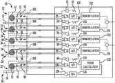
- FIG. 1is a schematic diagram of an inductive sensor device 10 , such as an eddy current sensor device for measuring changes in location of one or more targets.
- the device 10includes four operational (or active) sensor heads 12 , 14 , 16 , and 18 .
- the operational sensor heads 12 and 14are used as parts of a first sensor channel 20 for determining position of a first movable target 22
- the operational sensor heads 16 and 18are used as parts of a second sensor channel 24 for determining position of a second movable target 26 .
- the targets 22 and 26may be associated with movements of an optical device such as a mirror, with the targets 22 and 26 for example representing movement of the mirror (e.g., translational or tilting movements) in orthogonal directions.
- targets 22 and 26may be made of aluminum or another suitable material, and may have any of a variety of suitable shapes, such as being plates, bars, or disks.
- the device 10also includes a reference sensor head 32 that has a fixed reference target 34 associated with it, as parts of a reference channel 36 .
- the reference target 34does not move relative to the reference sensor head 32 , allowing the output of the reference sensor head 32 to be used to adjust the characteristics of the active or operational sensor heads 12 - 18 , for example to compensate for effects of changes of temperature.
- the reference target 34may be made of the same material as the targets 22 and 26 , and/or may have the same shape as the targets 22 and 26 .
- One or more current drivesapply a periodic drive current to the sensor heads 12 , 14 , 16 , 18 , and 32 .
- This currentis indicated in FIG. 1 by waveforms 42 , 44 , 46 , 48 , and 50 , which pass through respective current drive amplifiers 52 , 54 , 56 , 58 , and 60 , on the way to respective sensor coils 62 , 64 , 66 , 68 , and 70 .
- the drive currentmay be at a suitable frequency, for example at 500 kHz, producing oscillating magnetic fields in the sensor coils 62 - 70 .
- the sensor coils 62 - 70may be wound wire coils or flat spiral traces on a printed wiring board, to give non-limiting examples.
- the sensor heads 12 , 14 , 16 , 18 , and 32also have respective fixed capacitors 72 , 74 , 76 , 78 , and 80 , and respective variable capacitors 82 , 84 , 86 , 88 , and 90 that are coupled in parallel with the corresponding respective sensor coils 62 , 64 , 66 , 68 , and 70 .
- variable capacitors 82 - 90are examples of a broader category of variable electrical elements.
- Other types of variable electrical elementssuch as variable inductors, may be substituted for the variable capacitors 82 - 90 shown in the specific embodiment depicted in FIG. 1 , with types of elements (such as variable inductors) placed in series with the coils 62 - 70 instead of in parallel with the capacitors 82 - 90 .
- elementssuch as variable inductors
- Output signals from the sensor heads 12 , 14 , 16 , 18 , and 32are passed through respective sensing instrumentation amplifiers 92 , 94 , 96 , 98 , and 100 , and then through respective analog-to-digital (A/D) converters 102 , 104 , 106 , 108 , and 110 .
- the digitized signals from the operational sensor channels 20 and 24are then passed through demodulators 112 , 114 , 116 , and 118 , and the demodulated output signals are then combined to produce position indications regarding the positions of the targets 22 and 26 .
- Demodulationcan take the form of phase sensitive rectification, or DFT (Discrete Fourier Transform), or other means.
- Target positioncan be extracted from either amplitude or phase measurements
- the eddy currents through the inductor coils 62 , 64 and 66 , 68are affected in such a way as to change the effective inductance of the coil, thus shifting the resonance and allowing a means by which to measure position.
- the change in either amplitude or phase of the output signal of the sensor heads 12 , 14 , 16 , and 18can be used to estimate target position, using the processed signal alone or combined with other data (such as calibration data or a look-up table, or applying a linear least squares fit (or higher order curve) to the data) to produce an output of the object displacement detected by the sensor heads 12 , 14 , 16 , 18 of a given channel 20 , 24 .
- a sensor channel 20 , 24may be calibrated by moving the target position to known positions and comparing the sensor estimated target position to these known positions. The differences between the estimated position and known positions can then be used within the device 10 to reduce estimated position error via lookup table, or polynomial fit or other means.
- the digitized reference output signal of the reference sensor head 32is passed through a phase calculation module 122 in which changes in phase are detected, indicating changes in resonant frequency.
- Phasemay be detected through multiple means or mechanisms, such as (for example) a Discrete Fourier Transform (DFT). Since the reference target 34 does not move, any changes in the output reference signal are due to changes in characteristics of the reference channel 36 .
- Use of the reference channel 36allows isolation of such changes in system characteristics, for example caused by changes in temperature, keeping such changes separate from changes in output resulting from movement of targets. This allows for compensation of the system, through the use of the variable capacitors 82 , 84 , 86 , 88 , and 90 , to remove or at least greatly reduce the changes of system characteristics, such as those resulting from changes in temperature.
- output from the phase calculation module 122is expressed as a signal to change the value of the capacitance of the variable reference capacitor 90 , with the value changed so as to compensate for the changes in phase to the output of the reference sensor head 32 , to maintain the resonant frequency of the reference sensor head 32 .
- This signal for a value changeis passed through a digital-to-analog (D/A) converter 126 , and through a reference channel feedback amplifier 128 , before being sent on to the variable capacitors 82 , 84 , 86 , 88 , and 90 , to implement the capacitance adjustment.
- D/Adigital-to-analog
- the reference channel 36acts as a low-bandwidth closed feedback loop, with the capacitance of the variable reference capacitor 90 adjusted to maintain the output signal from the reference channel 36 constant, and with the same change being made in the variable capacitors 82 , 84 , 86 , and 88 of the operational sensor heads 12 - 18 .
- An alternative approachwould be to perform the reference calculation and corresponding adjustments on command, since the changes to be compensated for are slowly changing. Such calculations and operations may be performed in software, hardware, or firmware, or any combination thereof.
- the feedback signalsare described above as analog signals.
- the feedback signalscould be in the form of digital signals, with appropriate interfaces provided at the sensor heads.
- the arrangement and characteristics of the reference sensor head 32may be similar in many respects to the arrangement and characteristics of the operational sensor heads 12 - 18 .
- all of the fixed capacitors 72 - 80may have similar characteristics; all of the variable capacitors 82 - 90 may have similar characteristics; all of the drive amplifiers 52 - 60 may have similar characteristics; all of the sensor coils 62 - 70 may have similar characteristics; all of the sensing instrumentation amplifiers 92 - 100 may have similar characteristics; and/or all of the A/D converters 102 - 110 may have similar characteristics.
- the similarity in characteristics between the various corresponding parts of the sensor device 10aids in applying the tuning of the reference sensor head 32 to the operational sensor heads 12 - 18 .
- variable capacitors 82 - 90are one example of broader categories of variable electrical elements that may be adjusted to tune the sensor heads 12 - 18 .
- Another possible type of variable electrical elementis a variable inductor.
- Variable inductorsmay be provided as part of the sensor heads 12 - 18 and 32 , electrically coupled to the coils 62 - 70 , with the inductance of the variable inductors varied in order to tune the sensor heads 12 - 18 and 32 .
- Different types of variable elementsmay be used in the same sensor heads, for example with variable capacitors and/or variable inductors employed.
- the capacitors 72 - 90may be located close to their corresponding sensor coils 62 - 70 , away from an electronics module (or electronics box) 130 that houses other electrical/electronic/processing components of the sensor device 10 .
- the electronics module 130may include the amplifiers 52 - 60 , 92 - 100 , and/or 128 ; the A/D converters 102 - 110 ; the D/A converter 126 ; the demodulators 112 - 118 ; and/or the phase calculation module 122 .
- the sensor coils 62 , 64 , 66 , 68 , and 70may be located on respective substrates 142 , 144 , 146 , 148 , and 150 , with the capacitors 72 - 90 corresponding to each of the sensor coils 62 , 64 , 66 , 68 , and 70 also located on the corresponding substrates 142 , 144 , 146 , 148 , and 150 .
- the placement of the capacitors 72 - 90 close to the corresponding sensor coils 62 - 70enables another advantageous arrangement of the sensor device 10 , the use of four-wire connections for each of the sensor heads 12 - 18 and 32 .
- the elimination of lead and contact resistance from the sensor signal outputimproves accuracy of the signals used for determining position of the targets 22 and 26 , and improves the accuracy of the sensor head tuning based on the reference sensor head 32 .
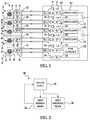
- FIG. 2shows a high-level flow chart for a method 200 for adjusting a sensor device, such as the device 10 ( FIG. 1 ).
- step 202the output of the reference sensor head 32 ( FIG. 1 ) is monitored, such as in by use of the phase calculation module 122 ( FIG. 1 ). Based on this monitoring, in step 204 adjustments are made in the reference sensor head 32 , such as in in the variable capacitor 90 , to maintain the resonant frequency of the reference senor head 32 .
- the steps 202 and 204are parts of a feedback loop, as described in greater detail above.
- the operational sensor heads 12 - 18are tuned or adjusted based on the adjustments to the reference sensor head 32 . As described earlier, these adjustments may involve identical adjustments to variable capacitors 82 - 90 of both the reference sensor head 32 and the operational sensor heads 12 - 18 .
- FIG. 3shows an alternative configuration, a sensor device 260 that differs from the sensor device 10 ( FIG. 1 ) in that the sensor device 260 has only two-wire connections, rather than the four-wire connections of the sensor device 10 , with drive signals and sensor head output signals running along the same wires between sensor heads 262 - 270 , and an electronics module (or electronics box) 280 .
- the sensor device 260is similar to the sensor device 10 .
- FIG. 4shows another alternative, a sensor device 310 that dispenses with the reference channel 36 ( FIG. 1 ) of the sensor device 10 ( FIG. 1 ). Since the feedback concept of the sensor device 10 is dispensed with, the sensor device 310 also does not include any variable capacitors, such as the variable capacitors 82 - 90 ( FIG. 1 ) of the sensor device 10 .
- the sensor device 310does have some advantageous characteristics, such as those resulting from placement of fixed capacitors 372 , 374 , 376 , and 378 close to respective sensor coils 362 , 364 , 366 , and 368 , for example with corresponding capacitors 372 - 328 and the coils 362 - 368 on respective substrates 382 , 384 , 386 , and 388 .
- the sensor device 310may share the four-wire interface with the sensor device 10 , with separate pairs of drive signal wires and sensor output signal wires between the sensor coils 362 - 368 and the electronics module or electronics box 390 .
- FIG. 5shows still another alternative, a sensor device 410 with two operational sensor heads 412 and 414 to track movement of a single target 422 , and a reference sensor head 432 operatively coupled to a fixed target 434 as part of a feedback loop.
- the reference sensor head 432is used to compensate for temperature changes (or other effects) by varying variable capacitors 442 , 444 , and 446 that are operatively coupled to respective sensor coils 462 , 464 , and 466 .
- the feedback processhas been explained above with regard to the sensor device 10 ( FIG. 1 ).
- the sensor device 410differs from the sensor device 10 in that the sensor device 410 has only two operational sensor heads 412 and 414 , as opposed to the four operational sensor heads 12 - 18 ( FIG. 1 ) of the sensor device 10 . It will be appreciated that any reasonable number of operational sensor heads may be in such a device, from a single operational sensor head to many such operational sensor heads.
- FIG. 6shows a sensor device 510 which is similar to the sensor device 10 ( FIG. 1 ) except that the variable capacitors 82 - 90 ( FIG. 1 ) have been replaced by variable electrical elements 582 , 584 , 586 , 588 , and 590 , which (as indicated earlier) may be variable capacitors, variable inductors, or some combination thereof.
- the variable electrical elements 582 - 590are depicted in FIG. 6 as variable inductors in series with coils 562 , 564 , 566 , 568 , and 570 , but could be more broadly other types of electrical elements.
- the sensor device 510may be similar to the sensor device 10 , having similar elements, similar features, and similar ways of functioning.
Landscapes
- Physics & Mathematics (AREA)
- General Physics & Mathematics (AREA)
- Life Sciences & Earth Sciences (AREA)
- Chemical & Material Sciences (AREA)
- Engineering & Computer Science (AREA)
- Remote Sensing (AREA)
- Electrochemistry (AREA)
- Health & Medical Sciences (AREA)
- General Life Sciences & Earth Sciences (AREA)
- Geophysics (AREA)
- Environmental & Geological Engineering (AREA)
- Chemical Kinetics & Catalysis (AREA)
- Electromagnetism (AREA)
- Geology (AREA)
- Analytical Chemistry (AREA)
- Biochemistry (AREA)
- General Health & Medical Sciences (AREA)
- Immunology (AREA)
- Pathology (AREA)
- Transmission And Conversion Of Sensor Element Output (AREA)
- Measurement Of Length, Angles, Or The Like Using Electric Or Magnetic Means (AREA)
Abstract
Description
Claims (18)
Priority Applications (7)
| Application Number | Priority Date | Filing Date | Title |
|---|---|---|---|
| US15/914,037US11054395B2 (en) | 2018-03-07 | 2018-03-07 | Inductive sensor device with reference sensor |
| KR1020207017154AKR102466607B1 (en) | 2018-03-07 | 2018-11-13 | Inductive sensor with reference sensor |
| EP18815848.9AEP3762685B1 (en) | 2018-03-07 | 2018-11-13 | Inductive sensor device with reference sensor |
| JP2020546111AJP7127141B2 (en) | 2018-03-07 | 2018-11-13 | Inductive sensor device with reference sensor |
| PCT/US2018/060618WO2019172967A1 (en) | 2018-03-07 | 2018-11-13 | Inductive sensor device with reference sensor |
| CA3093232ACA3093232A1 (en) | 2018-03-07 | 2018-11-13 | Inductive sensor device with reference sensor |
| IL276870AIL276870B (en) | 2018-03-07 | 2020-08-23 | Inductive sensor device with reference sensor |
Applications Claiming Priority (1)
| Application Number | Priority Date | Filing Date | Title |
|---|---|---|---|
| US15/914,037US11054395B2 (en) | 2018-03-07 | 2018-03-07 | Inductive sensor device with reference sensor |
Publications (2)
| Publication Number | Publication Date |
|---|---|
| US20190277803A1 US20190277803A1 (en) | 2019-09-12 |
| US11054395B2true US11054395B2 (en) | 2021-07-06 |
Family
ID=64661453
Family Applications (1)
| Application Number | Title | Priority Date | Filing Date |
|---|---|---|---|
| US15/914,037Active2038-11-28US11054395B2 (en) | 2018-03-07 | 2018-03-07 | Inductive sensor device with reference sensor |
Country Status (7)
| Country | Link |
|---|---|
| US (1) | US11054395B2 (en) |
| EP (1) | EP3762685B1 (en) |
| JP (1) | JP7127141B2 (en) |
| KR (1) | KR102466607B1 (en) |
| CA (1) | CA3093232A1 (en) |
| IL (1) | IL276870B (en) |
| WO (1) | WO2019172967A1 (en) |
Families Citing this family (2)
| Publication number | Priority date | Publication date | Assignee | Title |
|---|---|---|---|---|
| DE102019103670B4 (en)* | 2019-02-13 | 2024-07-25 | Balluff Gmbh | Inductive sensor and method for its operation |
| US20250076086A1 (en)* | 2023-08-28 | 2025-03-06 | Mitutoyo Corporation | Inductive position transducer system with impedance circuit portion |
Citations (34)
| Publication number | Priority date | Publication date | Assignee | Title |
|---|---|---|---|---|
| US4816759A (en) | 1987-10-28 | 1989-03-28 | Kaman Corporation | Inductive sensor for detecting displacement of adjacent surfaces |
| US5477473A (en) | 1992-04-02 | 1995-12-19 | Micro-Epsilon Messtechnik Gmbh & Co. Kg | Sensor-drive and signal-processing method |
| US5528446A (en) | 1994-07-05 | 1996-06-18 | Ford Motor Company | Integrated power module diagnostic unit |
| US5594344A (en) | 1995-08-09 | 1997-01-14 | Western Atlas International, Inc. | Method and apparatus for generating and detecting amplitude and phase modulated sensor signals |
| US5854553A (en) | 1996-06-19 | 1998-12-29 | Skf Condition Monitoring | Digitally linearizing eddy current probe |
| US5886519A (en) | 1997-01-29 | 1999-03-23 | Mitutoyo Corporation | Multi-scale induced current absolute position transducer |
| US6148669A (en) | 1998-06-29 | 2000-11-21 | U.S. Philips Corporation | Acceleration sensor with a spherical inductance influencing member |
| US6664782B2 (en) | 1999-10-22 | 2003-12-16 | Bently Nevada, Llc | Digital eddy current proximity system: apparatus and method |
| US6803757B2 (en) | 2001-10-02 | 2004-10-12 | Bentley Nevada, Llc | Multi-coil eddy current proximity probe system |
| US20050046593A1 (en) | 2003-08-28 | 2005-03-03 | Tulpule Bhalchandra R. | Reconfigurable sensor signal demodulation system |
| US6873149B1 (en) | 2003-11-26 | 2005-03-29 | General Electric Company | Method and system for eddy current proximity system noise reduction |
| US20070024274A1 (en) | 2005-07-28 | 2007-02-01 | Diehl Avionik Systeme Gmbh | Measurement configuration |
| US7324908B2 (en) | 2005-09-21 | 2008-01-29 | General Dynamics Advanced Information Systems, Inc. | System and method for temperature compensation of eddy current sensor waveform |
| US7358720B1 (en) | 2006-01-25 | 2008-04-15 | Simmonds Precision Products, Inc. | Proximity sensor interface |
| US20090140728A1 (en) | 2007-11-29 | 2009-06-04 | Rollins George E | Apparatus and methods for proximity sensing circuitry |
| US20110057668A1 (en) | 2009-09-04 | 2011-03-10 | Weihua Chen | Inductive proximity sensor |
| US8198888B2 (en) | 2004-10-08 | 2012-06-12 | Siemens Aktiengesellschaft | Method and system for determining the distance between a profiled surface and a functional surface moving in relation thereto by using measurement coils and a reference coil |
| EP2475964A1 (en) | 2009-09-08 | 2012-07-18 | Perception Sensors & Instrumentation Ltd | High temperature operation inductive position sensing device |
| US8542008B2 (en) | 2006-10-05 | 2013-09-24 | Shinko Electric Co., Ltd. | Displacement sensor |
| US20130249452A1 (en) | 2012-03-23 | 2013-09-26 | Kabushiki Kaisha Toshiba | Angle detector and motor drive controller |
| US20130271158A1 (en) | 2012-04-13 | 2013-10-17 | Sick Ag | Inductive proximity sensor |
| US8564281B2 (en)* | 2009-05-29 | 2013-10-22 | Calnetix Technologies, L.L.C. | Noncontact measuring of the position of an object with magnetic flux |
| US20140157897A1 (en)* | 2012-12-12 | 2014-06-12 | Raytheon Company | Hung Mass Accelerometer With Differential Eddy Current Sensing |
| US20140182395A1 (en) | 2011-06-16 | 2014-07-03 | Ams Ag | Arrangement and method for operating a sensor, in particular a bridge sensor, and a sensor arrangement |
| US20140300425A1 (en) | 2013-01-08 | 2014-10-09 | Maxim Integrated Products, Inc. | Electro-mechanical resonance loop |
| US20150190659A1 (en) | 2012-07-09 | 2015-07-09 | Koninklijke Philips N.V. | Acoustic radiation force magnetic resonance imaging |
| US20150362340A1 (en) | 2013-03-14 | 2015-12-17 | Carl Zeiss Smt Gmbh | Position sensor, sensor arrangement and lithography apparatus comprising position sensor |
| US20160025519A1 (en) | 2013-03-20 | 2016-01-28 | Schaeffler Technologies AG & Co. KG | Method and angle sensor for contactless measurement of an angle |
| CN105547126A (en) | 2016-02-01 | 2016-05-04 | 珠海格力节能环保制冷技术研究中心有限公司 | Eddy current displacement sensor |
| US20160169717A1 (en)* | 2013-08-12 | 2016-06-16 | Victor Zhitomirsky | Position sensor |
| US20160238412A1 (en) | 2013-10-11 | 2016-08-18 | Mecos Ag | Contactless sensor for determining rotor displacements |
| US9459369B2 (en) | 2012-10-05 | 2016-10-04 | Blue Line Engineering Company | Inductive sensor with demodulator |
| US20170234945A1 (en) | 2014-10-17 | 2017-08-17 | Koninklijke Philips N.V. | Spatially resolved metal detector |
| US20170319097A1 (en) | 2014-11-14 | 2017-11-09 | Koninklijke Philips N.V. | Magnetic resonance fingerprinting in slices along a one-dimensional extension |
Family Cites Families (3)
| Publication number | Priority date | Publication date | Assignee | Title |
|---|---|---|---|---|
| US8947186B2 (en)* | 2008-09-27 | 2015-02-03 | Witricity Corporation | Wireless energy transfer resonator thermal management |
| JP6210416B2 (en) | 2014-01-31 | 2017-10-11 | パナソニックIpマネジメント株式会社 | Position sensor |
| US9983026B2 (en) | 2014-09-25 | 2018-05-29 | Texas Instruments Incorporated | Multi-level rotational resolvers using inductive sensors |
- 2018
- 2018-03-07USUS15/914,037patent/US11054395B2/enactiveActive
- 2018-11-13CACA3093232Apatent/CA3093232A1/enactivePending
- 2018-11-13WOPCT/US2018/060618patent/WO2019172967A1/ennot_activeCeased
- 2018-11-13EPEP18815848.9Apatent/EP3762685B1/enactiveActive
- 2018-11-13KRKR1020207017154Apatent/KR102466607B1/enactiveActive
- 2018-11-13JPJP2020546111Apatent/JP7127141B2/enactiveActive
- 2020
- 2020-08-23ILIL276870Apatent/IL276870B/enunknown
Patent Citations (34)
| Publication number | Priority date | Publication date | Assignee | Title |
|---|---|---|---|---|
| US4816759A (en) | 1987-10-28 | 1989-03-28 | Kaman Corporation | Inductive sensor for detecting displacement of adjacent surfaces |
| US5477473A (en) | 1992-04-02 | 1995-12-19 | Micro-Epsilon Messtechnik Gmbh & Co. Kg | Sensor-drive and signal-processing method |
| US5528446A (en) | 1994-07-05 | 1996-06-18 | Ford Motor Company | Integrated power module diagnostic unit |
| US5594344A (en) | 1995-08-09 | 1997-01-14 | Western Atlas International, Inc. | Method and apparatus for generating and detecting amplitude and phase modulated sensor signals |
| US5854553A (en) | 1996-06-19 | 1998-12-29 | Skf Condition Monitoring | Digitally linearizing eddy current probe |
| US5886519A (en) | 1997-01-29 | 1999-03-23 | Mitutoyo Corporation | Multi-scale induced current absolute position transducer |
| US6148669A (en) | 1998-06-29 | 2000-11-21 | U.S. Philips Corporation | Acceleration sensor with a spherical inductance influencing member |
| US6664782B2 (en) | 1999-10-22 | 2003-12-16 | Bently Nevada, Llc | Digital eddy current proximity system: apparatus and method |
| US6803757B2 (en) | 2001-10-02 | 2004-10-12 | Bentley Nevada, Llc | Multi-coil eddy current proximity probe system |
| US20050046593A1 (en) | 2003-08-28 | 2005-03-03 | Tulpule Bhalchandra R. | Reconfigurable sensor signal demodulation system |
| US6873149B1 (en) | 2003-11-26 | 2005-03-29 | General Electric Company | Method and system for eddy current proximity system noise reduction |
| US8198888B2 (en) | 2004-10-08 | 2012-06-12 | Siemens Aktiengesellschaft | Method and system for determining the distance between a profiled surface and a functional surface moving in relation thereto by using measurement coils and a reference coil |
| US20070024274A1 (en) | 2005-07-28 | 2007-02-01 | Diehl Avionik Systeme Gmbh | Measurement configuration |
| US7324908B2 (en) | 2005-09-21 | 2008-01-29 | General Dynamics Advanced Information Systems, Inc. | System and method for temperature compensation of eddy current sensor waveform |
| US7358720B1 (en) | 2006-01-25 | 2008-04-15 | Simmonds Precision Products, Inc. | Proximity sensor interface |
| US8542008B2 (en) | 2006-10-05 | 2013-09-24 | Shinko Electric Co., Ltd. | Displacement sensor |
| US20090140728A1 (en) | 2007-11-29 | 2009-06-04 | Rollins George E | Apparatus and methods for proximity sensing circuitry |
| US8564281B2 (en)* | 2009-05-29 | 2013-10-22 | Calnetix Technologies, L.L.C. | Noncontact measuring of the position of an object with magnetic flux |
| US20110057668A1 (en) | 2009-09-04 | 2011-03-10 | Weihua Chen | Inductive proximity sensor |
| EP2475964A1 (en) | 2009-09-08 | 2012-07-18 | Perception Sensors & Instrumentation Ltd | High temperature operation inductive position sensing device |
| US20140182395A1 (en) | 2011-06-16 | 2014-07-03 | Ams Ag | Arrangement and method for operating a sensor, in particular a bridge sensor, and a sensor arrangement |
| US20130249452A1 (en) | 2012-03-23 | 2013-09-26 | Kabushiki Kaisha Toshiba | Angle detector and motor drive controller |
| US20130271158A1 (en) | 2012-04-13 | 2013-10-17 | Sick Ag | Inductive proximity sensor |
| US20150190659A1 (en) | 2012-07-09 | 2015-07-09 | Koninklijke Philips N.V. | Acoustic radiation force magnetic resonance imaging |
| US9459369B2 (en) | 2012-10-05 | 2016-10-04 | Blue Line Engineering Company | Inductive sensor with demodulator |
| US20140157897A1 (en)* | 2012-12-12 | 2014-06-12 | Raytheon Company | Hung Mass Accelerometer With Differential Eddy Current Sensing |
| US20140300425A1 (en) | 2013-01-08 | 2014-10-09 | Maxim Integrated Products, Inc. | Electro-mechanical resonance loop |
| US20150362340A1 (en) | 2013-03-14 | 2015-12-17 | Carl Zeiss Smt Gmbh | Position sensor, sensor arrangement and lithography apparatus comprising position sensor |
| US20160025519A1 (en) | 2013-03-20 | 2016-01-28 | Schaeffler Technologies AG & Co. KG | Method and angle sensor for contactless measurement of an angle |
| US20160169717A1 (en)* | 2013-08-12 | 2016-06-16 | Victor Zhitomirsky | Position sensor |
| US20160238412A1 (en) | 2013-10-11 | 2016-08-18 | Mecos Ag | Contactless sensor for determining rotor displacements |
| US20170234945A1 (en) | 2014-10-17 | 2017-08-17 | Koninklijke Philips N.V. | Spatially resolved metal detector |
| US20170319097A1 (en) | 2014-11-14 | 2017-11-09 | Koninklijke Philips N.V. | Magnetic resonance fingerprinting in slices along a one-dimensional extension |
| CN105547126A (en) | 2016-02-01 | 2016-05-04 | 珠海格力节能环保制冷技术研究中心有限公司 | Eddy current displacement sensor |
Non-Patent Citations (4)
| Title |
|---|
| Co-pending U.S. Appl. No. 15/864,097, filed Jan. 8, 2018. |
| Co-pending U.S. Appl. No. 16/056,916, filed Aug. 7, 2018. |
| International Search Report and Written Opinion for corresponding International Application No. PCT/US2018/060618 dated Feb. 19, 2019. |
| International Search Report and Written Opinion for International Application No. PCT/US2018/051689 dated Jan. 7, 2019. |
Also Published As
| Publication number | Publication date |
|---|---|
| US20190277803A1 (en) | 2019-09-12 |
| JP2021515230A (en) | 2021-06-17 |
| KR102466607B1 (en) | 2022-11-14 |
| WO2019172967A1 (en) | 2019-09-12 |
| JP7127141B2 (en) | 2022-08-29 |
| IL276870B (en) | 2022-02-01 |
| EP3762685B1 (en) | 2022-08-10 |
| CA3093232A1 (en) | 2019-09-12 |
| IL276870A (en) | 2020-10-29 |
| KR20200087219A (en) | 2020-07-20 |
| EP3762685A1 (en) | 2021-01-13 |
Similar Documents
| Publication | Publication Date | Title |
|---|---|---|
| US6828779B2 (en) | Circuit for compensating for time variation of temperature in an inductive sensor | |
| US20110128014A1 (en) | Position sensor | |
| JP2911828B2 (en) | Multi-parameter eddy current measurement system with parameter compensation | |
| US11054395B2 (en) | Inductive sensor device with reference sensor | |
| EP3096457B1 (en) | Proximity sensor | |
| US10001388B2 (en) | Circuit arrangement and method for controlling a displacement measurement sensor | |
| US10928223B2 (en) | Inductive sensor device | |
| US10816316B2 (en) | Inductive sensor device with local analog-to-digital converter | |
| EP1679492A1 (en) | Eddy-current sensor and magnetic bearing device | |
| CN1849517B (en) | Method and apparatus for measuring active, reactive power of system and module, impedance of electrical component | |
| JPH0257984A (en) | Circuit apparatus for application connected to inductive and capacitive device for non-destructive measurement of orm resistance of thin film | |
| US3244977A (en) | Electronic gaging device with linear output characteristics utilizing a series network of diodes as part of the metering circuit | |
| US20140002069A1 (en) | Eddy current probe | |
| JP4398911B2 (en) | Displacement sensor | |
| JPH08271204A (en) | Eddy current type displacement sensor | |
| KR20220124627A (en) | Tilt and curvature measurements of metal sheets in a rolling mill | |
| CA1262372A (en) | Method for the measurement of capacitances, in particular of low capacitances, wherein two references are used | |
| JP5777288B2 (en) | Method for calibrating evaluation circuit and evaluation circuit | |
| JPH06160006A (en) | Displacement detector |
Legal Events
| Date | Code | Title | Description |
|---|---|---|---|
| AS | Assignment | Owner name:RAYTHEON COMPANY, MASSACHUSETTS Free format text:ASSIGNMENT OF ASSIGNORS INTEREST;ASSIGNOR:IVES, PHILIP H.;REEL/FRAME:045129/0232 Effective date:20180306 | |
| FEPP | Fee payment procedure | Free format text:ENTITY STATUS SET TO UNDISCOUNTED (ORIGINAL EVENT CODE: BIG.); ENTITY STATUS OF PATENT OWNER: LARGE ENTITY | |
| STPP | Information on status: patent application and granting procedure in general | Free format text:NON FINAL ACTION MAILED | |
| STPP | Information on status: patent application and granting procedure in general | Free format text:RESPONSE TO NON-FINAL OFFICE ACTION ENTERED AND FORWARDED TO EXAMINER | |
| STPP | Information on status: patent application and granting procedure in general | Free format text:NON FINAL ACTION MAILED | |
| STPP | Information on status: patent application and granting procedure in general | Free format text:RESPONSE AFTER FINAL ACTION FORWARDED TO EXAMINER | |
| STPP | Information on status: patent application and granting procedure in general | Free format text:NOTICE OF ALLOWANCE MAILED -- APPLICATION RECEIVED IN OFFICE OF PUBLICATIONS | |
| STPP | Information on status: patent application and granting procedure in general | Free format text:PUBLICATIONS -- ISSUE FEE PAYMENT RECEIVED | |
| STPP | Information on status: patent application and granting procedure in general | Free format text:PUBLICATIONS -- ISSUE FEE PAYMENT VERIFIED | |
| STCF | Information on status: patent grant | Free format text:PATENTED CASE | |
| MAFP | Maintenance fee payment | Free format text:PAYMENT OF MAINTENANCE FEE, 4TH YEAR, LARGE ENTITY (ORIGINAL EVENT CODE: M1551); ENTITY STATUS OF PATENT OWNER: LARGE ENTITY Year of fee payment:4 |