US11054173B2 - Water heater with organic polymer coating - Google Patents
Water heater with organic polymer coatingDownload PDFInfo
- Publication number
- US11054173B2 US11054173B2US16/210,913US201816210913AUS11054173B2US 11054173 B2US11054173 B2US 11054173B2US 201816210913 AUS201816210913 AUS 201816210913AUS 11054173 B2US11054173 B2US 11054173B2
- Authority
- US
- United States
- Prior art keywords
- layer
- water
- heat exchanger
- water heater
- tank
- Prior art date
- Legal status (The legal status is an assumption and is not a legal conclusion. Google has not performed a legal analysis and makes no representation as to the accuracy of the status listed.)
- Active, expires
Links
- XLYOFNOQVPJJNP-UHFFFAOYSA-NwaterSubstancesOXLYOFNOQVPJJNP-UHFFFAOYSA-N0.000titleclaimsabstractdescription107
- 229920000620organic polymerPolymers0.000titleclaimsabstractdescription36
- 238000000576coating methodMethods0.000titleclaimsabstractdescription24
- 239000011248coating agentSubstances0.000titleclaimsabstractdescription23
- 239000011521glassSubstances0.000claimsabstractdescription26
- 210000003298dental enamelAnatomy0.000claimsabstractdescription22
- 238000000034methodMethods0.000claimsabstractdescription18
- 239000002184metalSubstances0.000claimsabstractdescription16
- 239000000843powderSubstances0.000claimsdescription45
- 230000001010compromised effectEffects0.000claimsdescription20
- 230000004907fluxEffects0.000claimsdescription20
- 238000010438heat treatmentMethods0.000claimsdescription15
- 230000001681protective effectEffects0.000claimsdescription6
- 230000004888barrier functionEffects0.000claimsdescription5
- 238000010304firingMethods0.000claimsdescription4
- 238000004090dissolutionMethods0.000claimsdescription3
- 238000001035dryingMethods0.000claimsdescription3
- 238000002844meltingMethods0.000claimsdescription3
- 230000008018meltingEffects0.000claimsdescription3
- 238000005507sprayingMethods0.000claimsdescription3
- 230000002378acidificating effectEffects0.000claims2
- 238000002485combustion reactionMethods0.000description12
- 238000010276constructionMethods0.000description10
- 239000007789gasSubstances0.000description7
- 239000003546flue gasSubstances0.000description6
- 229910000831SteelInorganic materials0.000description5
- 238000005260corrosionMethods0.000description5
- 230000007797corrosionEffects0.000description5
- 230000002401inhibitory effectEffects0.000description5
- 239000010959steelSubstances0.000description5
- 239000000758substrateSubstances0.000description5
- 230000007704transitionEffects0.000description4
- UGFAIRIUMAVXCW-UHFFFAOYSA-NCarbon monoxideChemical compound[O+]#[C-]UGFAIRIUMAVXCW-UHFFFAOYSA-N0.000description3
- 238000005336crackingMethods0.000description3
- 238000004952furnace firingMethods0.000description3
- 238000009413insulationMethods0.000description3
- 239000000203mixtureSubstances0.000description3
- CURLTUGMZLYLDI-UHFFFAOYSA-NCarbon dioxideChemical compoundO=C=OCURLTUGMZLYLDI-UHFFFAOYSA-N0.000description2
- 238000005422blastingMethods0.000description2
- 238000004140cleaningMethods0.000description2
- 238000004891communicationMethods0.000description2
- 239000002320enamel (paints)Substances0.000description2
- 239000012530fluidSubstances0.000description2
- 239000002245particleSubstances0.000description2
- 230000008569processEffects0.000description2
- 230000002035prolonged effectEffects0.000description2
- 230000009467reductionEffects0.000description2
- 238000003466weldingMethods0.000description2
- 238000009736wettingMethods0.000description2
- 229910002092carbon dioxideInorganic materials0.000description1
- 239000001569carbon dioxideSubstances0.000description1
- 230000015556catabolic processEffects0.000description1
- 230000000694effectsEffects0.000description1
- 230000003628erosive effectEffects0.000description1
- 239000011152fibreglassSubstances0.000description1
- 239000000446fuelSubstances0.000description1
- 239000007769metal materialSubstances0.000description1
- 230000005855radiationEffects0.000description1
- 239000007921spraySubstances0.000description1
Images


Classifications
- F—MECHANICAL ENGINEERING; LIGHTING; HEATING; WEAPONS; BLASTING
- F24—HEATING; RANGES; VENTILATING
- F24H—FLUID HEATERS, e.g. WATER OR AIR HEATERS, HAVING HEAT-GENERATING MEANS, e.g. HEAT PUMPS, IN GENERAL
- F24H1/00—Water heaters, e.g. boilers, continuous-flow heaters or water-storage heaters
- F24H1/18—Water-storage heaters
- F24H1/181—Construction of the tank
- F24H1/183—Inner linings
- F—MECHANICAL ENGINEERING; LIGHTING; HEATING; WEAPONS; BLASTING
- F24—HEATING; RANGES; VENTILATING
- F24H—FLUID HEATERS, e.g. WATER OR AIR HEATERS, HAVING HEAT-GENERATING MEANS, e.g. HEAT PUMPS, IN GENERAL
- F24H9/00—Details
- F24H9/14—Arrangements for connecting different sections, e.g. in water heaters
- F24H9/148—Arrangements of boiler components on a frame or within a casing to build the fluid heater, e.g. boiler
- B—PERFORMING OPERATIONS; TRANSPORTING
- B05—SPRAYING OR ATOMISING IN GENERAL; APPLYING FLUENT MATERIALS TO SURFACES, IN GENERAL
- B05D—PROCESSES FOR APPLYING FLUENT MATERIALS TO SURFACES, IN GENERAL
- B05D1/00—Processes for applying liquids or other fluent materials
- B05D1/02—Processes for applying liquids or other fluent materials performed by spraying
- B05D1/04—Processes for applying liquids or other fluent materials performed by spraying involving the use of an electrostatic field
- B05D1/06—Applying particulate materials
- B—PERFORMING OPERATIONS; TRANSPORTING
- B05—SPRAYING OR ATOMISING IN GENERAL; APPLYING FLUENT MATERIALS TO SURFACES, IN GENERAL
- B05D—PROCESSES FOR APPLYING FLUENT MATERIALS TO SURFACES, IN GENERAL
- B05D2202/00—Metallic substrate
- B—PERFORMING OPERATIONS; TRANSPORTING
- B05—SPRAYING OR ATOMISING IN GENERAL; APPLYING FLUENT MATERIALS TO SURFACES, IN GENERAL
- B05D—PROCESSES FOR APPLYING FLUENT MATERIALS TO SURFACES, IN GENERAL
- B05D2350/00—Pretreatment of the substrate
- B05D2350/60—Adding a layer before coating
- B—PERFORMING OPERATIONS; TRANSPORTING
- B05—SPRAYING OR ATOMISING IN GENERAL; APPLYING FLUENT MATERIALS TO SURFACES, IN GENERAL
- B05D—PROCESSES FOR APPLYING FLUENT MATERIALS TO SURFACES, IN GENERAL
- B05D7/00—Processes, other than flocking, specially adapted for applying liquids or other fluent materials to particular surfaces or for applying particular liquids or other fluent materials
- B05D7/22—Processes, other than flocking, specially adapted for applying liquids or other fluent materials to particular surfaces or for applying particular liquids or other fluent materials to internal surfaces, e.g. of tubes
- B05D7/227—Processes, other than flocking, specially adapted for applying liquids or other fluent materials to particular surfaces or for applying particular liquids or other fluent materials to internal surfaces, e.g. of tubes of containers, cans or the like
- C—CHEMISTRY; METALLURGY
- C23—COATING METALLIC MATERIAL; COATING MATERIAL WITH METALLIC MATERIAL; CHEMICAL SURFACE TREATMENT; DIFFUSION TREATMENT OF METALLIC MATERIAL; COATING BY VACUUM EVAPORATION, BY SPUTTERING, BY ION IMPLANTATION OR BY CHEMICAL VAPOUR DEPOSITION, IN GENERAL; INHIBITING CORROSION OF METALLIC MATERIAL OR INCRUSTATION IN GENERAL
- C23D—ENAMELLING OF, OR APPLYING A VITREOUS LAYER TO, METALS
- C23D5/00—Coating with enamels or vitreous layers
- C23D5/02—Coating with enamels or vitreous layers by wet methods
- F—MECHANICAL ENGINEERING; LIGHTING; HEATING; WEAPONS; BLASTING
- F24—HEATING; RANGES; VENTILATING
- F24H—FLUID HEATERS, e.g. WATER OR AIR HEATERS, HAVING HEAT-GENERATING MEANS, e.g. HEAT PUMPS, IN GENERAL
- F24H1/00—Water heaters, e.g. boilers, continuous-flow heaters or water-storage heaters
- F24H1/18—Water-storage heaters
- F24H1/20—Water-storage heaters with immersed heating elements, e.g. electric elements or furnace tubes
- F24H1/205—Water-storage heaters with immersed heating elements, e.g. electric elements or furnace tubes with furnace tubes
- F24H1/206—Water-storage heaters with immersed heating elements, e.g. electric elements or furnace tubes with furnace tubes with submerged combustion chamber
Definitions
- the present inventionrelates to a water heater having a metal substrate, and more specifically to protecting the metal substrate by an organic polymer coating.
- Glass enamel coatingsare traditionally used in hot water heaters to protect the metal substrate, but are subject to dissolution by hot water. Once the protective glass enamel coating has dissolved through to the substrate, then the substrate corrodes rapidly and is perforated through. At this point the water heater must be replaced.
- the inventionprovides a method of constructing a water heater in the steps of providing a tank having a metal interior tank wall, a heat exchanger positioned within the tank, coating the interior tank wall and the heat exchanger with a first layer comprising glass enamel, and coating a portion of the first layer with a second layer comprising an organic polymer to protect the portion of the first layer from exposure to water in the tank.
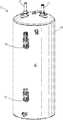
- FIG. 1is a perspective view of a water heater including a tank.
- FIG. 2is a cross-sectional schematic view of the tank of FIG. 1 .
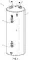
- FIG. 3is a cross-sectional side view of another water heater embodying the invention.
- FIG. 4is an enlarged cross-sectional view of a heat exchanger coil of the water heater of FIG. 3 .
- FIG. 1illustrates a water heater 10 with portions not illustrated for clarity purposes. More specifically, the water heater 10 includes a tank 14 to hold water to be heated. The water heater 10 further includes a source of heat (e.g., electrical elements, condenser coil, burner, etc.) for heating the water in the tank 14 .
- the water heater 10is an electrical water heater with electrical heating elements positioned within the tank 14 . The electrical heating elements are electrically connected via fittings 18 that extend through a sidewall of the tank 14 .
- the water in the tank 14is generally heated and maintained in a range of 110 to 140 degrees Fahrenheit.
- a water inlet pipe 22 and a water outlet pipe 26are coupled to and in fluid communication with an interior of the tank 14 .
- the water inlet pipe 22is used for supplying cold water to the tank 14 and the water outlet pipe 26 is used for drawing heated water from the tank 14 .
- the water heater 10may further include insulation (e.g., foam-in-place insulation or fiberglass batt insulation) around the tank 14 to reduce heat loss.
- the tank 14includes a tank wall 34 having an outer surface 30 and an oppositely-facing interior surface 38 that defines an interior space of the tank 14 .
- the tank wall 34may be fabricated from a metal material such as steel.
- the interior surface 38may be coated with a plurality of layers for inhibiting exposure of the interior tank wall 38 to water contained in the interior space of the tank 14 .
- the tank 14includes a first layer 42 positioned on the interior surface 38 and a second layer 46 positioned on the first layer 42 .
- the first layer 42comprises glass enamel to protect the tank wall 34 from direct exposure to water which could lead to failure of the metal tank wall 34 due to corrosion or cracking.
- the first layer 42is configured to protect the interior surface 38 from the corrosive effects of direct exposure to the water in the tank 14 .
- Glass enamelcan be compromised when exposure to high temperatures (e.g., above a “water temperature limit”), high acidity (e.g., above a “water acidity limit”), or high alkalinity (e.g., above a “water alkalinity limit”).
- the water acidity limit and the water alkalinity limitmay also be thought of as below and above, respectively, a glass enamel pH range (e.g., the pH range within the tolerance of the glass enamel).
- the term “compromised”may be defined as melting, dissolving, cracking, eroding, corroding, or any other kind of breakdown of the first layer 42 .
- the glass enamelhas a water temperature limit in the range of 131-208 degrees Fahrenheit (131-208° F.). In other exemplary constructions, the water temperature limit may be 160 degrees Fahrenheit (160° F.).
- the water acidity limitmay be a pH of 4 (i.e., the glass enamel may be compromised when exposed to a pH below 4).
- the water alkalinity limitmay be a pH of 10 (i.e., the glass enamel may be compromised when exposed to a pH above 10). Stated another way, the pH range for the glass enamel may be 4-10 (i.e., the glass enamel is at little or no risk of being compromised at a pH between 4-10, inclusive).
- the second layer 46forms a protective barrier on the first layer 42 (i.e., protecting the first layer 42 from direct exposure to water and high temperatures) for inhibiting the first layer 42 from being compromised due to water temperature, water acidity, or water alkalinity.
- the second layer 46comprises an organic polymer as prescribed in U.S. Pat. No. 8,277,912, incorporated herein by reference.
- the second layer 46is directly exposed to water in the tank 14 and protects the first layer 42 from direct exposure to the water. As such, the second layer 46 forms a protective barrier on the first layer 42 for slowing, inhibiting, or preventing the first layer 42 from being compromised.
- the second layer 46may extend the amount of time it takes for the first layer 42 to be compromised. Consequently, the second layer 46 may prevent early failure of the tank 14 such that a life expectancy of the tank 14 may be prolonged.
- the water heater 10 as described abovemay be constructed in a plurality of steps.
- a first stepincludes providing the tank 14 having the metal tank wall 34 . This may include forming the tank 14 by fully assembling all components of the tank 14 and welding. When the tank 14 is formed, an opening for the water inlet pipe 22 , an opening for the water outlet pipe 26 , openings for draining, and openings for safety valves may be included.
- the interior surface 38may be cleaned and blasted using abrasive particles. This may include cleaning and blasting all steel surfaces of the interior surface 38 .
- a second stepincludes coating the interior surface 38 with the first layer 42 comprising of glass enamel. This may include slush coating the interior surface 38 with the first layer 42 .
- the second stepmay include applying the first layer 42 in powder form as glass powder.
- the second stepmay include wetting the powder to form a wet mixture called a “slip.”
- the second stepmay further include slushing the slip (i.e., slip-slushing) onto the interior surface 38 . This may include slushing the slip on all of the steel surfaces by rotating the tank 14 .
- the second stepmay further include heating and curing the slip after it has been applied to the interior surface 38 . This may include drying the slip for at least 20 minutes at a temperature of at least 400 degrees Fahrenheit (400° F.).
- the first layer 42may then be heated by firing in the furnace (i.e., furnace firing) to bond the first layer 42 to the interior surface 38 .
- the first layermay be furnace fired at a temperature in the range of 1500 to 1600 degrees Fahrenheit (1500-1600° F.) or a temperature of at least 1500 degrees Fahrenheit (1500° F.) for a period of 5 to 10 minutes.
- a third stepincludes providing the organic polymer of the second layer 46 in powder form, positioning the organic polymer powder on the first layer 42 , and heating the second layer 46 .
- the organic polymer powdermay be electrostatically sprayed onto the first layer 42 by positively charging the organic polymer powder prior to the powder leaving the sprayer and grounding the tank 14 such that the powder is attracted to the interior surface 38 of the grounded tank 14 .
- the organic polymer powderis heated in an oven at a temperature in the range of 400 to 420 degrees Fahrenheit (400-420° F.) for at least 20 minutes to form the second layer 46 .
- the second layer 46has a thickness of at least 4 Mils (i.e., 101.6 Micrometers).
- FIG. 3illustrates another water heater 110 embodying the invention, with like components and features as the embodiment of the water heater 10 shown in FIGS. 1-2 being labeled with like reference numerals plus “100”.
- the water heater 110includes a tank 114 , a water inlet pipe 122 , and a water outlet pipe 126 .
- the water heater 110further includes a combustor 154 (shown schematically in FIG. 3 ).
- the combustor 154includes a gas burner 158 and a combustion chamber 162 .
- a flue 166is positioned in the tank 114 and is in fluid communication with the combustion chamber 162 .
- Hot flue gasesare generated by the gas burner 158 burning a combustible mixture of fuel (e.g., gas) and air within the combustion chamber 162 .
- the hot flue gasesare then directed from the combustion chamber 162 through the flue 166 to a flue gas outlet 174 .
- the burner 158fires downwardly into the combustion chamber 162 and may therefore be termed as a down-firing burner.
- the water heater 110includes high heat flux regions.
- the term “high heat flux region”is used to indicate a portion of the water heater 110 having special characteristics disclosed herein that experiences high heat which can lead to accelerated corrosion.
- examples of high heat flux regionsare regions that meet one or more of the following criteria: locations with line-of-sight contact to the burner, due to high flame temperatures or radiation heat transfer from the burner (“line-of-sight regions” indicated with “A”); transition locations from a larger chamber or tube to a smaller chamber or tube, due to a reduction in boundary layer thickness and some minor increases in turbulence resulting from an increase in velocity of the gas (“transition regions” indicated with “B”); elbows or bends resulting in high heat flux due to increased gas turbulation and reduction of the boundary layer thickness adjacent portions of the elbow (“elbow regions” indicated with “C”); and locations within approximately three burner lengths or widths from the burner 158 , resulting in high heat flux due to high gas temperature (“proximal regions” indicated with “D”).
- Line-of-sightmeans there is an unobstructed path between the source of heat and the region, such that the region is exposed to radiant heat from the heat source.
- An example of a line-of-sight region Ais the sidewall of the combustion chamber 162 alongside the lower end of the burner 158 in FIG. 3 .
- An example of a transition region Bis the transition from a narrowing portion 178 of the combustion chamber 162 to an elbow 182 in FIG. 3 .
- an elbow region Cis the elbow 182 .
- the term “burner length”may mean the major dimension of the burner and “burner width” may mean the minor dimension of the burner.
- the burnerhas a burner length 158 L and a burner width 158 W.
- Proximal regionsexperience high heat flux because the temperature of the products of combustion is highest close to the burner.
- Examples of proximal regions Dare the portions of the combustion chambers 162 near the portion of the burner 158 .
- the high heat flux regions A-Dare not mutually exclusive. A region may qualify as a high heat flux region under multiple categories. For example, a line-of-sight region A is often also going to be a proximal region D.
- the combustion chamber 162 and the flue 166are heated by the hot flue gases produced by the gas burner 158 , and the heat is transferred to the water within the tank 114 . Therefore, the combustion chamber 162 and the flue 166 may be defined as a heat exchanger 150 of the water heater 110 .
- an inner surface 138 of the tank 114is exposed to the water within the tank 114 .
- an outer surface 170 of the heat exchanger 150i.e., an outer surface of the combustion chamber 162 and an outer surface of the flue 166
- the water in the tank 114is in contact with the water-facing surfaces (or more technically, with coatings 142 , 146 on the water-facing surfaces, as further discussed below).
- the interior surface 138 of the tank 114 and/or the outer surface 170 of the heat exchanger 150may be coated with a plurality of layers for inhibiting exposure of the water-facing surfaces to the water contained in the interior space of the tank 114 .
- the heat exchanger 150includes a first layer 142 positioned on the outer surface 170 and a second layer 146 positioned on the first layer 142 .
- the interior tank 114(or portions thereof) may also include the first layer 142 positioned on the interior surface 138 , and the second layer 146 positioned on the first layer 142 (similar to the first embodiment of FIGS. 1 and 2 ).
- the first and second layers 142 , 146may be positioned on the heat exchanger 150 and/or the tank 114 based on one or more of a predetermined (i.e., expected) water temperature range, the performance trying to be achieved, the application of the water heater 110 , and a lifetime of the water heater 110 .
- the first layer 142comprises glass enamel and the second layer 146 comprises an organic polymer, as described above with respect to the first embodiment.
- the first layer 142is configured to protect the heat exchanger 150 from direct exposure to water which could lead to failure of the metal heat exchanger 150 due to corrosion or cracking.
- the glass enamelcan be compromised (i.e., when exposure to high temperatures such as high water temperature, high acidity, and high alkalinity).
- the second layer 146forms a protective barrier on the first layer 142 (i.e., protecting the first layer 142 from direct exposure to water and high temperatures) for inhibiting the first layer 142 from being compromised such as due to exposure of water, water temperature, water acidity, or water alkalinity.
- first and second layers 142 , 146are positioned on the high heat flux regions of the heat exchanger 150 (although the first and second layers 142 , 146 may also be positioned on other portions or all of the heat exchanger 150 and or the interior surface 138 of the tank 114 ).
- the portions of the heat exchanger 150 having the high heat flux regionsmay compromise the fastest.
- the second layer 146is positioned on the first layer 142 in particular at these high heat flux regions to slow, inhibit, or prevent the first layer 142 from being compromised.
- the water heater 110may be constructed in a plurality of steps.
- a first stepincludes providing the tank 114 having the metal tank wall 134 . This may include forming the tank 114 by fully assembling all components of the tank 114 and welding. Specifically, in this embodiment, the metal heat exchanger 150 is positioned within the tank 114 .
- an opening for the water inlet pipe 122 , an opening for the water outlet pipe 126 , openings for the flue gas outlet 174 , openings for draining, and openings for safety valvesmay be included.
- the interior surface 138may be cleaned and blasted using abrasive particles. This may include cleaning and blasting all steel surfaces of the interior surface 138 .
- a second stepincludes coating the interior surface 138 of the tank 114 and the outer surface 170 of the heat exchanger 150 with the first layer 142 comprising of glass enamel. This may include slush coating the interior surface 138 as described above with respect to the water heater 10 of the first embodiment, but also slush coating the heat exchanger 150 with the first layer 142 .
- the second stepmay include applying the first layer 142 in powder form as glass powder.
- the second stepmay include wetting the powder to form a wet mixture called a “slip.”
- the second stepmay further include slushing the slip (i.e., slip-slushing) onto the interior surface 138 and the heat exchanger 150 .
- the second stepmay further include heating and curing the slip after it has been applied to the interior surface 138 and the heat exchanger 150 .
- Thismay include drying the slip for at least 20 minutes at a temperature of at least 400 degrees Fahrenheit (400° F.).
- the first layer 142may then be heated by firing in the furnace (i.e., furnace firing) to bond the first layer 142 to the interior surface 138 and to the heat exchanger 150 .
- the first layer 142may be furnace fired at a temperature in the range of 1500 to 1600 degrees Fahrenheit (1500-1600° F.) or a temperature of at least 1500 degrees Fahrenheit (1500° F.) for a period of 5 to 10 minutes.
- the water-facing surfaces of the water heater 110are lined or coated with the glass enamel of the first layer 142 to reduce susceptibility to corrosion in the second step.
- bubblesmay form within the first layer 142 during the furnace firing due to carbon dioxide within the slip pushing out as the first layer 142 is heated. Specifically, these bubbles may form near the surface of the first layer 142 opposite the outer surface 170 of the heat exchanger 150 or opposite the interior surface 138 of the tank 114 .
- the bubblesmay form an interconnected bubble structure within the first layer 142 .
- a third stepincludes providing the organic polymer of the second layer 146 in powder form, positioning the organic polymer powder on the first layer 142 , and heating the second layer 146 . More specifically, the organic polymer powder may be electrostatically sprayed onto the first layer 142 by positively charging the organic polymer powder prior to the powder leaving the sprayer and grounding the tank 114 such that the powder is attracted to the interior surface 138 of the grounded tank 114 and to the heat exchanger 150 positioned within the tank 114 .
- the organic polymer powdermay be electrostatically sprayed using a Tribo powder coating gun.
- the Tribo powder coating gunis inserted into one of the openings provided in the tank 114 that fluidly connect to the inlet pipe 122 , the outlet pipe 126 , the flue gas outlet opening, or a drain opening (not shown).
- the Tribo powder coating gunis inserted in the water inlet pipe opening and an end of the Tribo powder coating gun is positioned proximate a bottom of the heat exchanger.
- the Tribo powder coating gunsubsequently begins spraying from the bottom of the heat exchanger 150 to a top of the heat exchanger 150 .
- the Tribo powder coating gunmay electrostatically spray for about two minutes.
- the organic polymer powderis applied to the first layer 142 positioned on the interior surface 138 of the tank 114 and the heat exchanger 150 .
- the tank 114forms an enclosure such that there is no need to control the direction of spraying of the organic polymer powder.
- the enclosurehas a cylindrical shape.
- the organic polymer powderis directed toward a coil of the heat exchanger 150 by the Tribo powder coating gun. Therefore, the organic polymer powder may be applied to only certain portions of the first layer 142 positioned on the interior surface 138 of the tank 114 as the organic polymer powder is being electrostatically sprayed toward the heat exchanger 150 . In other words, portions of the interior surface 138 of the tank 114 may not be electrostatically sprayed with the organic polymer powder of the second layer 146 .
- the third stepfurther includes heating the organic polymer powder.
- the organic polymer powderis heated in an oven at a temperature in the range of 400 to 420 degrees Fahrenheit (400-420° F.) for at least 20 minutes to form the second layer 146 .
- the third stepmay further include allowing the tank 114 and/or the first layer 142 to cool to 120 degrees Fahrenheit (120° F.) prior to applying the second layer 146 .
- the second layer 146has a thickness of at least 4 Mils (i.e., 101.6 Micrometers).
- the organic polymer powdermay melt into the voids or recessed areas where the bubbles were, which may provide a better hold for the second layer 46 , 146 thereby increasing the adhesion of the second layer 46 , 146 to the first layer 42 , 142 .
- the heating in the third stepis believed to compromise the first layer 42 , 142 a minimum amount (only where the second layer 46 , 146 is applied, and only at the surface of the first layer 42 , 142 where the bubbles are formed) such that the second layer 46 , 146 may better adhere to the first layer 42 , 142 .
- the processactually appears to achieve better protection of the first layer 42 , 142 from corrosion by allowing adhesion or an increase in adhesion of the second layer 46 , 146 to the first layer 42 , 142 .
- Another possibility that is considered for the increased adhesion, in particular with respect to the water heater 110is that, although the coil of the heat exchanger 150 includes multiple bends and curves such that the applying of the second layer 146 in powder form may be difficult to cover the total surface area of the coil, the organic polymer powder may meet up or join with, during heating, nearby organic polymer powder positioned on other portions of the bends and curves to form a sleeve 186 ( FIG. 4 ).
- the processallows the second layer 146 to be specifically applied to the high heat flux regions of the heat exchanger 150 .
- the high heat flux regionsare at the highest temperature with respect to other portions of the water heater 110 when the water heater 110 is operating as described above.
- the high heat flux regionsare also exposed to the water within the tank 114 .
- the second layer 146 provided on the heat exchanger 150 in particular at the high heat flux regionsmay slow, inhibit, or prevent the first layer 142 on the heat exchanger 150 from being compromised. More specifically, the second layer 146 may extend the amount of time it takes for the first layer 142 to be compromised. Consequently, the second layer 146 may prevent early failure of the heat exchanger 150 such that a life expectancy of the water heater 110 may be prolonged.
Landscapes
- Engineering & Computer Science (AREA)
- Physics & Mathematics (AREA)
- Thermal Sciences (AREA)
- Chemical & Material Sciences (AREA)
- Combustion & Propulsion (AREA)
- Mechanical Engineering (AREA)
- General Engineering & Computer Science (AREA)
- Heat-Pump Type And Storage Water Heaters (AREA)
Abstract
Description
Claims (24)
Priority Applications (1)
| Application Number | Priority Date | Filing Date | Title |
|---|---|---|---|
| US16/210,913US11054173B2 (en) | 2017-12-06 | 2018-12-05 | Water heater with organic polymer coating |
Applications Claiming Priority (2)
| Application Number | Priority Date | Filing Date | Title |
|---|---|---|---|
| US201762595385P | 2017-12-06 | 2017-12-06 | |
| US16/210,913US11054173B2 (en) | 2017-12-06 | 2018-12-05 | Water heater with organic polymer coating |
Publications (2)
| Publication Number | Publication Date |
|---|---|
| US20190170394A1 US20190170394A1 (en) | 2019-06-06 |
| US11054173B2true US11054173B2 (en) | 2021-07-06 |
Family
ID=66658995
Family Applications (1)
| Application Number | Title | Priority Date | Filing Date |
|---|---|---|---|
| US16/210,913Active2039-03-14US11054173B2 (en) | 2017-12-06 | 2018-12-05 | Water heater with organic polymer coating |
Country Status (3)
| Country | Link |
|---|---|
| US (1) | US11054173B2 (en) |
| CN (1) | CN111602010B (en) |
| WO (1) | WO2019113229A1 (en) |
Families Citing this family (3)
| Publication number | Priority date | Publication date | Assignee | Title |
|---|---|---|---|---|
| CN111041484B (en)* | 2019-12-29 | 2024-03-19 | 东莞市天美新自动化设备有限公司 | Online automatic enamel spraying system for outer wall of water heater liner |
| CN112779538B (en)* | 2020-03-16 | 2023-03-17 | 青岛经济技术开发区海尔热水器有限公司 | Inner container enameling tool |
| US12398924B1 (en)* | 2023-08-25 | 2025-08-26 | John Darcy Bolton | Modular reversible water heater design |
Citations (49)
| Publication number | Priority date | Publication date | Assignee | Title |
|---|---|---|---|---|
| US2428526A (en)* | 1945-01-29 | 1947-10-07 | Mcgraw Electric Co | Anticorrosion tank |
| US2842840A (en) | 1954-02-11 | 1958-07-15 | Smith Corp A O | Method of fabricating glass coated metallic articles |
| US3207358A (en) | 1961-07-27 | 1965-09-21 | Gen Electric | Water storage tanks and methods of making the same |
| US3324280A (en) | 1964-08-06 | 1967-06-06 | Frank E Cheney | Insulated metal sheath heating element for electric water heaters |
| US3655610A (en) | 1970-05-21 | 1972-04-11 | Du Pont | Fluoropolymer coating compositions |
| GB1322084A (en) | 1970-03-20 | 1973-07-04 | Oreal | Container and method of manufacture |
| US4099641A (en) | 1976-02-10 | 1978-07-11 | Stiebel Eltron Gmbh & Co. Kg | Pressure tank for hot-water heaters |
| US4150164A (en) | 1974-01-02 | 1979-04-17 | W. R. Grace & Co. | Process for heating cylindrical containers with a plasma arc generated flame |
| US4191304A (en) | 1976-02-10 | 1980-03-04 | Stiebel Eltron Gmbh & Co. Kg | Pressure tank for hot-water heaters |
| US4263499A (en) | 1979-03-26 | 1981-04-21 | Romance Joseph S | Immersion heater with thermal cutoff |
| US4296799A (en) | 1979-05-29 | 1981-10-27 | Steele Richard S | Solar water tank and method of making same |
| US4313400A (en) | 1979-06-08 | 1982-02-02 | Amtrol Inc. | Lined metal tank with heat shield, indirect fired water heater and method of making same |
| FR2506753A1 (en) | 1981-05-29 | 1982-12-03 | Tech Nle Exploit Soc | Anticorrosive coating compsn. for water heating tank - contg. alumina cement, silica, epoxy! resin and hardener |
| DE3407777A1 (en) | 1984-03-02 | 1985-09-12 | Richard 3150 Peine Vetter | Device for heating water, in particular hot-water boiler |
| US4879801A (en) | 1986-12-11 | 1989-11-14 | A. O. Smith Corporation | Cathodically protected water heater |
| US4966790A (en) | 1986-09-26 | 1990-10-30 | Mitsui Petrochemical Industries, Ltd. | Coating compositions |
| DE4012643A1 (en) | 1990-04-20 | 1990-12-06 | Stefan Schaefer | Efficient element for water heaters - is polyester of polyimide film, silk screen printed with conductor pattern, laid up with copper contact plus plain film, and hot pressed |
| US4981112A (en)* | 1989-12-06 | 1991-01-01 | Pvi Industries, Inc. | Potable hot water storage vessel and method of manufacture |
| US5069956A (en) | 1989-05-30 | 1991-12-03 | Kansai Paint Co., Ltd. | Multilayer coating for the interior surface of a can |
| US5217140A (en)* | 1988-04-11 | 1993-06-08 | State Industries, Inc. | Tank construction and method of manufacture |
| CA2114858A1 (en) | 1993-02-03 | 1994-08-04 | Lloyd S. Steirer | Nickel-organic polymer coating method and water apparatus |
| US5501012A (en) | 1994-02-14 | 1996-03-26 | Southcorp Water Heaters Usa, Inc. | Tank lining method |
| US5522523A (en) | 1994-02-14 | 1996-06-04 | Southcorp Water Heaters Usa, Inc. | Water heater having flexible liner and method for making the same |
| US5728423A (en) | 1995-03-27 | 1998-03-17 | Rogerson; L. Keith | Method and apparatus for internally and externally coating enclosed metallic structures |
| US5855747A (en)* | 1997-04-04 | 1999-01-05 | Aos Holding Company | Performance enhancing coating for water heater |
| US6061499A (en) | 1997-03-31 | 2000-05-09 | Structural North America | Composite instantaneous water heater |
| CN2377490Y (en) | 1999-06-23 | 2000-05-10 | 温州市热水器总厂 | Internal chamber for water heater |
| CN1295921A (en) | 1999-11-10 | 2001-05-23 | 屠登富 | Internal container of steel-plastics composite water heater and production method thereof |
| CN2526727Y (en) | 2002-01-24 | 2002-12-18 | 山东小鸭集团热水器有限公司 | Scale-proof corrosion-proof water heater |
| CN2532411Y (en) | 2002-02-05 | 2003-01-22 | 王荣华 | Double-liner pressure-loaded water-heater |
| CN1431129A (en) | 2003-01-27 | 2003-07-23 | 卢雄文 | Hollow antisepsis container and its mfg. method |
| JP2003232595A (en) | 2002-02-08 | 2003-08-22 | Daikin Ind Ltd | Thermal storage device |
| US20040034154A1 (en) | 2002-06-06 | 2004-02-19 | Georgia-Pacific Resins Corporation | Epoxide-type formaldehyde free insulation binder |
| EP1428762A1 (en) | 2001-09-17 | 2004-06-16 | Takeuchi Press Industries Co., Ltd. | Metal container having coating applied to inner surface thereof and method for production thereof |
| US20040254328A1 (en) | 2001-10-31 | 2004-12-16 | Kazutoshi Haraguchi | Curable epoxy resin compositions and process for production thereof |
| US20050003082A1 (en) | 2003-01-29 | 2005-01-06 | Roelofs Robert R. | Method of powder coating weldable substrates |
| US20050048218A1 (en) | 2003-08-29 | 2005-03-03 | Weidman Larry G. | Process for coating substrates with polymeric compositions |
| CN2830967Y (en) | 2005-07-15 | 2006-10-25 | 广东万家乐燃气具有限公司 | Heat exchanger of condensing gas water heater |
| EP1867400A1 (en)* | 2006-06-16 | 2007-12-19 | Baltimore Aircoil Company, Inc. | liquid vessel liner and method of application |
| CN201575598U (en) | 2010-01-11 | 2010-09-08 | 欧永源 | Inner tank of electric water heater |
| US20100269345A1 (en)* | 2009-04-28 | 2010-10-28 | Aos Holding Company | Membrane seal for water heater tank spuds |
| US20100281899A1 (en)* | 2009-05-08 | 2010-11-11 | Stone Mountain Technologies, Inc. | Gas-fired heat pump water heater |
| US8277912B2 (en)* | 2008-02-20 | 2012-10-02 | Aos Holding Company | Organic polymer coatings for water containers |
| US8807093B2 (en) | 2011-05-19 | 2014-08-19 | Bock Water Heaters, Inc. | Water heater with multiple heat exchanging stacks |
| US9044779B2 (en) | 2010-04-29 | 2015-06-02 | Akzo Nobel Coatings International B.V. | Method for applying a powder coating |
| US20160221009A1 (en)* | 2012-10-10 | 2016-08-04 | Eurosider S.A.S. Di Milli Ottavio & C. | Method and apparatus for electrostatic painting |
| US9657398B2 (en) | 2013-10-31 | 2017-05-23 | U.S. Water Services Inc. | Corrosion inhibiting compositions |
| US20180051907A1 (en)* | 2016-08-19 | 2018-02-22 | Jozef Boros | Electric water heater having internal heat concentrator |
| US10240814B1 (en)* | 2017-09-25 | 2019-03-26 | Miclau—S.R.I.Inc. | Double glass coated tank for high temperature water heaters |
Family Cites Families (2)
| Publication number | Priority date | Publication date | Assignee | Title |
|---|---|---|---|---|
| CN202145052U (en)* | 2011-06-09 | 2012-02-15 | 广东万和新电气股份有限公司 | Water-storage hot water supply device with anti-corrosion device |
| CN105921363A (en)* | 2016-04-20 | 2016-09-07 | 天津巨龙暖通设备开发有限公司 | After-treatment integrated machine for heating radiators |
- 2018
- 2018-12-05CNCN201880085509.7Apatent/CN111602010B/enactiveActive
- 2018-12-05USUS16/210,913patent/US11054173B2/enactiveActive
- 2018-12-05WOPCT/US2018/064096patent/WO2019113229A1/ennot_activeCeased
Patent Citations (50)
| Publication number | Priority date | Publication date | Assignee | Title |
|---|---|---|---|---|
| US2428526A (en)* | 1945-01-29 | 1947-10-07 | Mcgraw Electric Co | Anticorrosion tank |
| US2842840A (en) | 1954-02-11 | 1958-07-15 | Smith Corp A O | Method of fabricating glass coated metallic articles |
| US3207358A (en) | 1961-07-27 | 1965-09-21 | Gen Electric | Water storage tanks and methods of making the same |
| US3324280A (en) | 1964-08-06 | 1967-06-06 | Frank E Cheney | Insulated metal sheath heating element for electric water heaters |
| GB1322084A (en) | 1970-03-20 | 1973-07-04 | Oreal | Container and method of manufacture |
| US3655610A (en) | 1970-05-21 | 1972-04-11 | Du Pont | Fluoropolymer coating compositions |
| US4150164A (en) | 1974-01-02 | 1979-04-17 | W. R. Grace & Co. | Process for heating cylindrical containers with a plasma arc generated flame |
| US4099641A (en) | 1976-02-10 | 1978-07-11 | Stiebel Eltron Gmbh & Co. Kg | Pressure tank for hot-water heaters |
| US4191304A (en) | 1976-02-10 | 1980-03-04 | Stiebel Eltron Gmbh & Co. Kg | Pressure tank for hot-water heaters |
| US4263499A (en) | 1979-03-26 | 1981-04-21 | Romance Joseph S | Immersion heater with thermal cutoff |
| US4296799A (en) | 1979-05-29 | 1981-10-27 | Steele Richard S | Solar water tank and method of making same |
| US4313400A (en) | 1979-06-08 | 1982-02-02 | Amtrol Inc. | Lined metal tank with heat shield, indirect fired water heater and method of making same |
| FR2506753A1 (en) | 1981-05-29 | 1982-12-03 | Tech Nle Exploit Soc | Anticorrosive coating compsn. for water heating tank - contg. alumina cement, silica, epoxy! resin and hardener |
| DE3407777A1 (en) | 1984-03-02 | 1985-09-12 | Richard 3150 Peine Vetter | Device for heating water, in particular hot-water boiler |
| US4966790A (en) | 1986-09-26 | 1990-10-30 | Mitsui Petrochemical Industries, Ltd. | Coating compositions |
| US4879801A (en) | 1986-12-11 | 1989-11-14 | A. O. Smith Corporation | Cathodically protected water heater |
| US5217140A (en)* | 1988-04-11 | 1993-06-08 | State Industries, Inc. | Tank construction and method of manufacture |
| US5069956A (en) | 1989-05-30 | 1991-12-03 | Kansai Paint Co., Ltd. | Multilayer coating for the interior surface of a can |
| US4981112A (en)* | 1989-12-06 | 1991-01-01 | Pvi Industries, Inc. | Potable hot water storage vessel and method of manufacture |
| DE4012643A1 (en) | 1990-04-20 | 1990-12-06 | Stefan Schaefer | Efficient element for water heaters - is polyester of polyimide film, silk screen printed with conductor pattern, laid up with copper contact plus plain film, and hot pressed |
| CA2114858A1 (en) | 1993-02-03 | 1994-08-04 | Lloyd S. Steirer | Nickel-organic polymer coating method and water apparatus |
| US5501012A (en) | 1994-02-14 | 1996-03-26 | Southcorp Water Heaters Usa, Inc. | Tank lining method |
| US5522523A (en) | 1994-02-14 | 1996-06-04 | Southcorp Water Heaters Usa, Inc. | Water heater having flexible liner and method for making the same |
| US5728423A (en) | 1995-03-27 | 1998-03-17 | Rogerson; L. Keith | Method and apparatus for internally and externally coating enclosed metallic structures |
| US6061499A (en) | 1997-03-31 | 2000-05-09 | Structural North America | Composite instantaneous water heater |
| US5855747A (en)* | 1997-04-04 | 1999-01-05 | Aos Holding Company | Performance enhancing coating for water heater |
| CN2377490Y (en) | 1999-06-23 | 2000-05-10 | 温州市热水器总厂 | Internal chamber for water heater |
| CN1295921A (en) | 1999-11-10 | 2001-05-23 | 屠登富 | Internal container of steel-plastics composite water heater and production method thereof |
| EP1428762A1 (en) | 2001-09-17 | 2004-06-16 | Takeuchi Press Industries Co., Ltd. | Metal container having coating applied to inner surface thereof and method for production thereof |
| US20040254328A1 (en) | 2001-10-31 | 2004-12-16 | Kazutoshi Haraguchi | Curable epoxy resin compositions and process for production thereof |
| CN2526727Y (en) | 2002-01-24 | 2002-12-18 | 山东小鸭集团热水器有限公司 | Scale-proof corrosion-proof water heater |
| CN2532411Y (en) | 2002-02-05 | 2003-01-22 | 王荣华 | Double-liner pressure-loaded water-heater |
| JP2003232595A (en) | 2002-02-08 | 2003-08-22 | Daikin Ind Ltd | Thermal storage device |
| US20040034154A1 (en) | 2002-06-06 | 2004-02-19 | Georgia-Pacific Resins Corporation | Epoxide-type formaldehyde free insulation binder |
| CN1431129A (en) | 2003-01-27 | 2003-07-23 | 卢雄文 | Hollow antisepsis container and its mfg. method |
| US20050003082A1 (en) | 2003-01-29 | 2005-01-06 | Roelofs Robert R. | Method of powder coating weldable substrates |
| US20050048218A1 (en) | 2003-08-29 | 2005-03-03 | Weidman Larry G. | Process for coating substrates with polymeric compositions |
| CN2830967Y (en) | 2005-07-15 | 2006-10-25 | 广东万家乐燃气具有限公司 | Heat exchanger of condensing gas water heater |
| EP1867400A1 (en)* | 2006-06-16 | 2007-12-19 | Baltimore Aircoil Company, Inc. | liquid vessel liner and method of application |
| US8277912B2 (en)* | 2008-02-20 | 2012-10-02 | Aos Holding Company | Organic polymer coatings for water containers |
| EP2245379B1 (en)* | 2008-02-20 | 2017-09-13 | AOS Holding Company | Organic polymer coatings for water containers |
| US20100269345A1 (en)* | 2009-04-28 | 2010-10-28 | Aos Holding Company | Membrane seal for water heater tank spuds |
| US20100281899A1 (en)* | 2009-05-08 | 2010-11-11 | Stone Mountain Technologies, Inc. | Gas-fired heat pump water heater |
| CN201575598U (en) | 2010-01-11 | 2010-09-08 | 欧永源 | Inner tank of electric water heater |
| US9044779B2 (en) | 2010-04-29 | 2015-06-02 | Akzo Nobel Coatings International B.V. | Method for applying a powder coating |
| US8807093B2 (en) | 2011-05-19 | 2014-08-19 | Bock Water Heaters, Inc. | Water heater with multiple heat exchanging stacks |
| US20160221009A1 (en)* | 2012-10-10 | 2016-08-04 | Eurosider S.A.S. Di Milli Ottavio & C. | Method and apparatus for electrostatic painting |
| US9657398B2 (en) | 2013-10-31 | 2017-05-23 | U.S. Water Services Inc. | Corrosion inhibiting compositions |
| US20180051907A1 (en)* | 2016-08-19 | 2018-02-22 | Jozef Boros | Electric water heater having internal heat concentrator |
| US10240814B1 (en)* | 2017-09-25 | 2019-03-26 | Miclau—S.R.I.Inc. | Double glass coated tank for high temperature water heaters |
Non-Patent Citations (3)
| Title |
|---|
| International Search Report and Written Opinion for Application No. PCT/US2018/064096 dated Mar. 5, 2019 (14 pages). |
| Office Action issued by the China National Intellectual Property Administration for Application No. 201880085509.7 dated Apr. 22, 2021 (15 pages including English translation). |
| Tiwari, "Clearing the confusion about the coating and material of the tank in water heaters," Bijli Bachao, <https://bijlibachao.com/water-heaters/coating-storage-water-heater-thermoplastic-stainless-steel-enamel-coating-glasslined.html> dated May 8, 2017. |
Also Published As
| Publication number | Publication date |
|---|---|
| CN111602010A (en) | 2020-08-28 |
| WO2019113229A1 (en) | 2019-06-13 |
| CN111602010B (en) | 2021-12-07 |
| US20190170394A1 (en) | 2019-06-06 |
Similar Documents
| Publication | Publication Date | Title |
|---|---|---|
| US11054173B2 (en) | Water heater with organic polymer coating | |
| KR100806942B1 (en) | Apparatus and method for coating 3-layer polyethylene and ceramics on steel pipes | |
| JPS6124058B2 (en) | ||
| US20160090843A1 (en) | Turbine components with stepped apertures | |
| CN105457861A (en) | Turbine component coating processes and turbine components | |
| CN102679086A (en) | Intermediate-frequency heating repaired opening construction technology for thermal contraction band of buried steel pipeline | |
| CN109863347A (en) | Immersion-type burner heating device and molten metal keep furnace | |
| US3203404A (en) | Water heater with heat insulating coating on tubes | |
| JP6132084B2 (en) | Method for providing stress reduction in an assembled tube wall of a steam generator | |
| EP1979677B1 (en) | Longevity and performance improvements to flare tips | |
| EP3441695A1 (en) | Glass-coated water heater constructed of multiple metals | |
| CN104111124A (en) | Anti-corrosion device of temperature element of high-pressure cylinder of steam turbine | |
| JP7048116B2 (en) | Glass material spraying device | |
| JP6722585B2 (en) | Integrated sintering method for microcracking and erosion resistance of heat shields | |
| EP2631322B1 (en) | Alloy-coated boiler component | |
| KR20120061606A (en) | Hearth roll of pre heating section in continuous galvanizing line | |
| RU2111409C1 (en) | Method of insulation of welded joints of pipe lines erected from steel pipes with manufacture enamel coats | |
| JPS6128826B2 (en) | ||
| RU2776607C1 (en) | Corrosion-resistant bushing for internal protection of pipelines | |
| RU2315899C1 (en) | Method of deposition of the protective coating on the pipeline | |
| KR200416779Y1 (en) | Tube for heat exchanger with double protection film | |
| KR102600126B1 (en) | Method for preventing red brick breakaway of coke quenching tower | |
| JP6652145B2 (en) | Heat exchange device and heat exchange method in radiant tube, and heating unit | |
| JP5376306B2 (en) | How to paint front and back | |
| CN107029963B (en) | Pipeline outer wall coating maintenance device |
Legal Events
| Date | Code | Title | Description |
|---|---|---|---|
| FEPP | Fee payment procedure | Free format text:ENTITY STATUS SET TO UNDISCOUNTED (ORIGINAL EVENT CODE: BIG.); ENTITY STATUS OF PATENT OWNER: LARGE ENTITY | |
| STPP | Information on status: patent application and granting procedure in general | Free format text:DOCKETED NEW CASE - READY FOR EXAMINATION | |
| STPP | Information on status: patent application and granting procedure in general | Free format text:NON FINAL ACTION MAILED | |
| AS | Assignment | Owner name:A. O. SMITH CORPORATION, WISCONSIN Free format text:ASSIGNMENT OF ASSIGNORS INTEREST;ASSIGNORS:KUO, MING C.;ROSE, NATHANIEL ARNELL;VOSS, BRITTNEY NICOLE;AND OTHERS;SIGNING DATES FROM 20200529 TO 20201008;REEL/FRAME:054077/0046 | |
| STPP | Information on status: patent application and granting procedure in general | Free format text:RESPONSE AFTER FINAL ACTION FORWARDED TO EXAMINER | |
| STPP | Information on status: patent application and granting procedure in general | Free format text:NOTICE OF ALLOWANCE MAILED -- APPLICATION RECEIVED IN OFFICE OF PUBLICATIONS | |
| STPP | Information on status: patent application and granting procedure in general | Free format text:AWAITING TC RESP., ISSUE FEE NOT PAID | |
| STPP | Information on status: patent application and granting procedure in general | Free format text:AWAITING TC RESP, ISSUE FEE PAYMENT RECEIVED | |
| STPP | Information on status: patent application and granting procedure in general | Free format text:PUBLICATIONS -- ISSUE FEE PAYMENT VERIFIED | |
| STCF | Information on status: patent grant | Free format text:PATENTED CASE | |
| MAFP | Maintenance fee payment | Free format text:PAYMENT OF MAINTENANCE FEE, 4TH YEAR, LARGE ENTITY (ORIGINAL EVENT CODE: M1551); ENTITY STATUS OF PATENT OWNER: LARGE ENTITY Year of fee payment:4 |