US11052603B2 - Additive manufacturing system having stowable cutting mechanism - Google Patents
Additive manufacturing system having stowable cutting mechanismDownload PDFInfo
- Publication number
- US11052603B2 US11052603B2US16/382,054US201916382054AUS11052603B2US 11052603 B2US11052603 B2US 11052603B2US 201916382054 AUS201916382054 AUS 201916382054AUS 11052603 B2US11052603 B2US 11052603B2
- Authority
- US
- United States
- Prior art keywords
- print head
- cutting mechanism
- selectively
- actuator
- matrix
- Prior art date
- Legal status (The legal status is an assumption and is not a legal conclusion. Google has not performed a legal analysis and makes no representation as to the accuracy of the status listed.)
- Expired - Fee Related, expires
Links
Images


Classifications
- B—PERFORMING OPERATIONS; TRANSPORTING
- B29—WORKING OF PLASTICS; WORKING OF SUBSTANCES IN A PLASTIC STATE IN GENERAL
- B29C—SHAPING OR JOINING OF PLASTICS; SHAPING OF MATERIAL IN A PLASTIC STATE, NOT OTHERWISE PROVIDED FOR; AFTER-TREATMENT OF THE SHAPED PRODUCTS, e.g. REPAIRING
- B29C64/00—Additive manufacturing, i.e. manufacturing of three-dimensional [3D] objects by additive deposition, additive agglomeration or additive layering, e.g. by 3D printing, stereolithography or selective laser sintering
- B29C64/20—Apparatus for additive manufacturing; Details thereof or accessories therefor
- B29C64/205—Means for applying layers
- B29C64/209—Heads; Nozzles
- B—PERFORMING OPERATIONS; TRANSPORTING
- B29—WORKING OF PLASTICS; WORKING OF SUBSTANCES IN A PLASTIC STATE IN GENERAL
- B29C—SHAPING OR JOINING OF PLASTICS; SHAPING OF MATERIAL IN A PLASTIC STATE, NOT OTHERWISE PROVIDED FOR; AFTER-TREATMENT OF THE SHAPED PRODUCTS, e.g. REPAIRING
- B29C64/00—Additive manufacturing, i.e. manufacturing of three-dimensional [3D] objects by additive deposition, additive agglomeration or additive layering, e.g. by 3D printing, stereolithography or selective laser sintering
- B29C64/30—Auxiliary operations or equipment
- B29C64/307—Handling of material to be used in additive manufacturing
- B—PERFORMING OPERATIONS; TRANSPORTING
- B29—WORKING OF PLASTICS; WORKING OF SUBSTANCES IN A PLASTIC STATE IN GENERAL
- B29C—SHAPING OR JOINING OF PLASTICS; SHAPING OF MATERIAL IN A PLASTIC STATE, NOT OTHERWISE PROVIDED FOR; AFTER-TREATMENT OF THE SHAPED PRODUCTS, e.g. REPAIRING
- B29C64/00—Additive manufacturing, i.e. manufacturing of three-dimensional [3D] objects by additive deposition, additive agglomeration or additive layering, e.g. by 3D printing, stereolithography or selective laser sintering
- B29C64/30—Auxiliary operations or equipment
- B29C64/386—Data acquisition or data processing for additive manufacturing
- B29C64/393—Data acquisition or data processing for additive manufacturing for controlling or regulating additive manufacturing processes
- B—PERFORMING OPERATIONS; TRANSPORTING
- B29—WORKING OF PLASTICS; WORKING OF SUBSTANCES IN A PLASTIC STATE IN GENERAL
- B29C—SHAPING OR JOINING OF PLASTICS; SHAPING OF MATERIAL IN A PLASTIC STATE, NOT OTHERWISE PROVIDED FOR; AFTER-TREATMENT OF THE SHAPED PRODUCTS, e.g. REPAIRING
- B29C70/00—Shaping composites, i.e. plastics material comprising reinforcements, fillers or preformed parts, e.g. inserts
- B29C70/04—Shaping composites, i.e. plastics material comprising reinforcements, fillers or preformed parts, e.g. inserts comprising reinforcements only, e.g. self-reinforcing plastics
- B29C70/28—Shaping operations therefor
- B29C70/30—Shaping by lay-up, i.e. applying fibres, tape or broadsheet on a mould, former or core; Shaping by spray-up, i.e. spraying of fibres on a mould, former or core
- B29C70/38—Automated lay-up, e.g. using robots, laying filaments according to predetermined patterns
- B—PERFORMING OPERATIONS; TRANSPORTING
- B33—ADDITIVE MANUFACTURING TECHNOLOGY
- B33Y—ADDITIVE MANUFACTURING, i.e. MANUFACTURING OF THREE-DIMENSIONAL [3-D] OBJECTS BY ADDITIVE DEPOSITION, ADDITIVE AGGLOMERATION OR ADDITIVE LAYERING, e.g. BY 3-D PRINTING, STEREOLITHOGRAPHY OR SELECTIVE LASER SINTERING
- B33Y30/00—Apparatus for additive manufacturing; Details thereof or accessories therefor
- B—PERFORMING OPERATIONS; TRANSPORTING
- B33—ADDITIVE MANUFACTURING TECHNOLOGY
- B33Y—ADDITIVE MANUFACTURING, i.e. MANUFACTURING OF THREE-DIMENSIONAL [3-D] OBJECTS BY ADDITIVE DEPOSITION, ADDITIVE AGGLOMERATION OR ADDITIVE LAYERING, e.g. BY 3-D PRINTING, STEREOLITHOGRAPHY OR SELECTIVE LASER SINTERING
- B33Y50/00—Data acquisition or data processing for additive manufacturing
- B33Y50/02—Data acquisition or data processing for additive manufacturing for controlling or regulating additive manufacturing processes
- B—PERFORMING OPERATIONS; TRANSPORTING
- B29—WORKING OF PLASTICS; WORKING OF SUBSTANCES IN A PLASTIC STATE IN GENERAL
- B29C—SHAPING OR JOINING OF PLASTICS; SHAPING OF MATERIAL IN A PLASTIC STATE, NOT OTHERWISE PROVIDED FOR; AFTER-TREATMENT OF THE SHAPED PRODUCTS, e.g. REPAIRING
- B29C64/00—Additive manufacturing, i.e. manufacturing of three-dimensional [3D] objects by additive deposition, additive agglomeration or additive layering, e.g. by 3D printing, stereolithography or selective laser sintering
- B29C64/10—Processes of additive manufacturing
- B29C64/165—Processes of additive manufacturing using a combination of solid and fluid materials, e.g. a powder selectively bound by a liquid binder, catalyst, inhibitor or energy absorber
- B—PERFORMING OPERATIONS; TRANSPORTING
- B29—WORKING OF PLASTICS; WORKING OF SUBSTANCES IN A PLASTIC STATE IN GENERAL
- B29K—INDEXING SCHEME ASSOCIATED WITH SUBCLASSES B29B, B29C OR B29D, RELATING TO MOULDING MATERIALS OR TO MATERIALS FOR MOULDS, REINFORCEMENTS, FILLERS OR PREFORMED PARTS, e.g. INSERTS
- B29K2105/00—Condition, form or state of moulded material or of the material to be shaped
- B29K2105/06—Condition, form or state of moulded material or of the material to be shaped containing reinforcements, fillers or inserts
- B29K2105/08—Condition, form or state of moulded material or of the material to be shaped containing reinforcements, fillers or inserts of continuous length, e.g. cords, rovings, mats, fabrics, strands or yarns
- B—PERFORMING OPERATIONS; TRANSPORTING
- B33—ADDITIVE MANUFACTURING TECHNOLOGY
- B33Y—ADDITIVE MANUFACTURING, i.e. MANUFACTURING OF THREE-DIMENSIONAL [3-D] OBJECTS BY ADDITIVE DEPOSITION, ADDITIVE AGGLOMERATION OR ADDITIVE LAYERING, e.g. BY 3-D PRINTING, STEREOLITHOGRAPHY OR SELECTIVE LASER SINTERING
- B33Y10/00—Processes of additive manufacturing
Definitions
- the present disclosurerelates generally to additive manufacturing and, more particularly, to a system for additively manufacturing a continuous-fiber composite structure and a stowable mechanism for cutting the continuous fiber.
- Continuous fiber 3D printinginvolves the use of continuous fibers embedded within a matrix discharging from a moveable print head.
- the matrixcan be a traditional thermoplastic, a powdered metal, a liquid resin (e.g., a UV curable and/or two-part resin), or a combination of any of these and other known matrixes.
- a cure enhancere.g., a UV light, an ultrasonic emitter, a heat source, a heat sink, a catalyst supply, etc.
- This curingoccurs almost immediately, allowing for unsupported structures to be fabricated in free space.
- CF3DTMprovides for increased strength and free-space fabrication
- the continuous fiber discharging from the print headmay need to be severed at the end of each fabrication pass.
- the disclosed system and cutting mechanismare directed to addressing this issue and/or other problems of the prior art.
- the present disclosureis directed to a system for additively manufacturing a composite structure.
- the systemmay include a print head configured to discharge a continuous reinforcement that is at least partially wetted with a matrix, and a support configured to move the print head in at least one dimension during discharge.
- the systemmay also include a cutting mechanism connected to at least one of the print head and the support.
- the cutting mechanismmay be configured to selectively sever the continuous reinforcement from the print head.
- the cutting mechanismmay include a cutting implement, a first actuator configured to move the cutting implement from a stowed position to a deployed position, and a second actuator configured to engage the cutting implement with the continuous reinforcement.
- the present disclosureis directed to another system for additively manufacturing a composite structure.
- This systemmay include a print head configured to discharge a continuous reinforcement that is at least partially wetted with a matrix, a support configured to move the print head in multiple dimensions during discharge, and a cure enhancer configured to initiate curing of the matrix at discharge.
- the systemmay also include a cutting mechanism connected to at least one of the print head and the support.
- the cutting mechanismmay be configured to selectively sever the continuous reinforcement from the print head.
- the cutting mechanismmay include shears, a first actuator configured to move the shears from a stowed position to a deployed position, and a second actuator configured to at least one of open and close the shears.
- the systemmay additionally include a controller configured to cause the support to move the print head, to selectively energize the first and second actuators, and to selectively activate the cure enhancer.
- the present disclosureis directed to another system for additively manufacturing a composite structure.
- This systemmay include a print head configured to discharge a continuous reinforcement that is at least partially wetted with a matrix, a support configured to move the print head in multiple dimensions during discharge, and a cure enhancer configured to initiate curing of the matrix at discharge.
- the systemmay also include a controller configured to selectively activate the cure enhancer, and to selectively cause the print head to discharge the continuous reinforcement and the matrix in overlapping layers to increase a z-height dimension.
- the controllermay also be configured to selectively cause the support to step the print head a distance in the z-height dimension between each overlapping layer, and to selectively adjust the distance of the step as a function of at least one of the z-height dimension and a number of layers overlapping in the z-height dimension.
- FIG. 1is a diagrammatic illustration of an exemplary disclosed additive manufacturing system
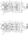
- FIGS. 2, 3, and 4are side-view illustrations of an exemplary print head and cutting mechanism that may be utilized with the additive manufacturing system of FIG. 1 ;
- FIGS. 4, 5, 6, 7, 8, and 9are side-, enlarged-, and isometric-view illustrations of another exemplary print head and cutting mechanism that may be utilized with the additive manufacturing system of FIG. 1 .
- FIG. 1illustrates an exemplary system 10 , which may be used to continuously manufacture a composite structure 12 having any desired cross-sectional shape (e.g., ellipsoidal, polygonal, etc.).
- System 10may include at least a moveable support 14 and a print head (“head”) 16 .
- Head 16may be coupled to and moved by support 14 .
- support 14is a robotic arm capable of moving head 16 in multiple directions during fabrication of structure 12 , such that a resulting longitudinal axis of structure 12 is three-dimensional. It is contemplated, however, that support 14 could alternatively be an overhead gantry or a hybrid gantry/arm also capable of moving head 16 in multiple directions during fabrication of structure 12 .
- support 14is shown as being capable of multi-axis (e.g., six or more axes) movement, it is contemplated that any other type of support 14 capable of moving head 16 in the same or in a different manner could also be utilized, if desired.
- a drivemay mechanically couple head 16 to support 14 and may include components that cooperate to move and/or supply power or materials to head 16 .
- Head 16may be configured to receive or otherwise contain a matrix.
- the matrixmay include any type of material (e.g., a liquid resin, such as a zero-volatile organic compound resin; a powdered metal; etc.) that is curable.
- Exemplary matrixesinclude thermosets, single- or multi-part epoxy resins, polyester resins, cationic epoxies, acrylated epoxies, urethanes, esters, thermoplastics, photopolymers, polyepoxides, thiols, alkenes, thiol-enes, reversible resins (e.g., Triazolinedione, a covalent-adaptable network, a spatioselective reversible resin, etc.) and more.
- Triazolinedionee.g., Triazolinedione, a covalent-adaptable network, a spatioselective reversible resin, etc.
- the matrix inside head 16may be pressurized, for example by an external device (e.g., an extruder or another type of pump—not shown) that is fluidly connected to head 16 via a corresponding conduit (not shown).
- the matrix pressuremay be generated completely inside of head 16 by a similar type of device.
- the matrixmay be gravity-fed through and/or mixed within head 16 .
- the matrix inside head 16may need to be kept cool and/or dark to inhibit premature curing; while in other instances, the matrix may need to be kept warm for similar reasons. In either situation, head 16 may be specially configured (e.g., insulated, chilled, and/or warmed) to provide for these needs.
- the matrixmay be used to coat, encase, or otherwise at least partially surround (e.g., wet) any number of continuous reinforcements (e.g., separate fibers, tows, rovings, ribbons, and/or sheets of material) and, together with the reinforcements, make up at least a portion (e.g., a wall) of composite structure 12 .
- the reinforcementsmay be stored within (e.g., on separate internal spools—not shown) or otherwise passed through head 16 (e.g., fed from one or more external spools—not shown).
- the reinforcementsmay be of the same type and have the same diameter and cross-sectional shape (e.g., circular, square, flat, hollow, solid, etc.), or of a different type with different diameters and/or cross-sectional shapes.
- the reinforcementsmay include, for example, carbon fibers, vegetable fibers, wood fibers, mineral fibers, glass fibers, metallic wires, optical tubes, etc. It should be noted that the term “reinforcement” is meant to encompass both structural and non-structural types of continuous materials that can be at least partially encased in the matrix discharging from head 16 .
- the reinforcementsmay be exposed to (e.g., coated with) the matrix while the reinforcements are inside head 16 , while the reinforcements are being passed to head 16 (e.g., as a prepreg material), and/or while the reinforcements are discharging from head 16 , as desired.
- the matrix, dry reinforcements, and/or reinforcements that are already exposed to the matrixmay be transported into head 16 in any manner apparent to one skilled in the art.
- the matrix and reinforcementmay be discharged from a nozzle 18 of head 16 via at least two different modes of operation.
- a first mode of operationthe matrix and reinforcement are extruded (e.g., pushed under pressure and/or mechanical force) from nozzle 18 , as head 16 is moved by support 14 to create the 3-dimensional shape of structure 12 .
- a second mode of operationat least the reinforcement is pulled from nozzle 18 , such that a tensile stress is created in the reinforcement during discharge.
- the matrixmay cling to the reinforcement and thereby also be pulled from nozzle 18 along with the reinforcement, and/or the matrix may be discharged from nozzle 18 under pressure along with the pulled reinforcement.
- the resulting tension in the reinforcementmay increase a strength of structure 12 (e.g., by aligning the reinforcements, inhibiting buckling, equally distributing loads, etc.), while also allowing for a greater length of unsupported structure 12 to have a straighter trajectory (e.g., by creating moments that oppose gravity).
- the reinforcementmay be pulled from nozzle 18 as a result of head 16 moving away from an anchor point 20 .
- a length of matrix-impregnated reinforcementmay be pulled and/or pushed from nozzle 18 , deposited onto a stationary anchor point 20 , and cured, such that the discharged material adheres to anchor point 20 .
- head 16may be moved away from anchor point 20 , and the relative movement may cause additional reinforcement to be pulled from nozzle 18 .
- the movement of the reinforcement through head 16could be assisted (e.g., via internal feed mechanisms), if desired.
- the discharge rate of the reinforcement from nozzle 18may primarily be the result of relative movement between head 16 and anchor point 20 , such that tension is created within the reinforcement.
- Nozzle 18may be fluidly connected to a matrix reservoir 22 .
- matrix reservoir 22is shown as being at least partially inside of head 16 , it should be noted that matrix reservoir 22 and/or another wetting mechanism could alternatively be located separately from (e.g., upstream of) head 16 .
- Nozzle 18may be a generally cylindrical component having an upstream or base end in communication with matrix reservoir 22 , a downstream or discharge tip, and one or more passages that extend from the base end to the tip end. It is contemplated that, in some embodiments, nozzle 18 may be omitted, if desired.
- any number of reinforcementsmay be passed axially through reservoir 22 (or another wetting mechanism—not shown), where at least some matrix-wetting occurs (matrix represented as M in FIGS. 2-9 ), and discharged from head 16 via nozzle 18 .
- One or more orificesmay be located at the tip end of nozzle 18 to accommodate passage of the matrix-wetted reinforcements.
- a single generally circular orificeis utilized. It is contemplated, however, that multiple circular orifices could be used.
- orifices of another shapee.g., a rectangular shape
- One or more cure enhancersmay be mounted proximate head 16 (e.g., around nozzle 18 or only at a trailing side of nozzle 18 ) and configured to enhance a cure rate and/or quality of the matrix as it is discharged from nozzle 18 .
- Cure enhancer 26may be controlled to selectively expose internal and/or external surfaces of structure 12 to cure energy (e.g., light energy, electromagnetic radiation, vibrations, heat, a chemical catalyst or hardener, etc.) during the formation of structure 12 .
- the cure energymay increase a rate of chemical reaction occurring within the matrix, sinter the material, harden the material, or otherwise cause the material to cure as it discharges from nozzle 18 .
- a controller 28may be provided and communicatively coupled with support 14 , head 16 , and any number and type of cure enhancers 26 .
- Controller 28may embody a single processor or multiple processors that include a means for controlling an operation of system 10 .
- Controller 28may include one or more general- or special-purpose processors or microprocessors.
- Controller 28may further include or be associated with a memory for storing data such as, for example, design limits, performance characteristics, operational instructions, matrix characteristics, reinforcement characteristics, characteristics of structure 12 , and corresponding parameters of each component of system 10 .
- Various other known circuitsmay be associated with controller 28 , including power supply circuitry, signal-conditioning circuitry, solenoid/motor driver circuitry, communication circuitry, and other appropriate circuitry.
- controller 28may be capable of communicating with other components of system 10 via wired and/or wireless transmission.
- One or more mapsmay be stored in the memory of controller 28 and used during fabrication of structure 12 .
- Each of these mapsmay include a collection of data in the form of models, lookup tables, graphs, and/or equations.
- the mapsare used by controller 28 to determine desired characteristics of cure enhancers 26 , the associated matrix, and/or the associated reinforcements at different locations within structure 12 .
- the characteristicsmay include, among others, a type, quantity, and/or configuration of reinforcement and/or matrix to be discharged at a particular location within structure 12 , and/or an amount, intensity, shape, and/or location of desired curing.
- Controller 28may then correlate operation of support 14 (e.g., the location and/or orientation of head 16 ) and/or the discharge of material from head 16 (a type of material, desired performance of the material, cross-linking requirements of the material, a discharge rate, etc.) with the operation of cure enhancers 26 , such that structure 12 is produced in a desired manner.
- support 14e.g., the location and/or orientation of head 16
- discharge of material from head 16a type of material, desired performance of the material, cross-linking requirements of the material, a discharge rate, etc.
- a cutting mechanism 30may be provided for this purpose.
- cutting mechanism 30is mounted directly to head 16 . It is contemplated, however, that cutting mechanism 30 could alternatively be mounted to support 14 and/or to a different support that is separate from support 14 (e.g., mounted to another robotic arm).
- FIGS. 2-5illustrate an exemplary head 16 and cutting mechanism 30 that may be used together to selectively discharge and sever the matrix-wetted and/or dry continuous reinforcements of composite structure 12 .
- cutting mechanism 30may include, among other things, a cutting implement (e.g., shears) 32 and a motorized linkage arrangement (“arrangement”—shown in FIGS. 4 and 5 ) 34 .
- Shears 32may be actively opened and actively closed to selectively grasp and/or sever the continuous reinforcement. It is contemplated, however, that shears 32 could be only actively closed and passively opened (e.g., via a spring—not shown), if desired. It is also contemplated that shears 32 could be double-acting, wherein each opening and each closing would effect severing of the continuous reinforcement.
- Arrangement 34may operatively mount shears 32 to a side (e.g., a trialing side) of head 16 and be selectively energized (e.g., by controller 28 —referring to FIG. 1 ) to cause shears 32 to open (shown in FIG. 3 ) and/or close (shown in FIG. 2 ) and also to move from a stowed position (shown in FIGS. 2-4 ) to a deployed position (shown in FIG. 5 ).
- primary surfacese.g., rightmost surfaces shown in FIG. 4
- the primary surfaces of shears 32may be generally perpendicular (e.g., within 0-15°) to the central axis of nozzle 18 .
- Shears 32may include at least one (e.g., first and second) arms 36 , 38 , each having a blade (e.g., a smooth, serrated, straight, and/or curved edge) 40 formed at one end and a lever 42 formed at an opposing second end.
- a common fastenere.g., a rivet, a bolt, or a screw
- arms 36 , 38may be pivoted about fastener 44 .
- a force applied to levers 42 that urges levers 42 away from each othermay cause arms 36 , 38 to pivot in opposing directions and move blades 40 towards each other (i.e., to close) to close on or otherwise engage the continuous reinforcement.
- a force applied to levers 42 that urges levers 42 towards each othermay cause arms 36 , 38 to pivot and move blades 40 away from other (i.e., to open).
- one or more actuators of arrangement 34may function to apply the above-described forces.
- a single rotary actuator (e.g., an electrical stepper motor) 48may generate both of the forces described above for use in actively opening and actively closing arms 36 , 38 .
- Rotary actuator 48may be connected to arms 36 , 38 by way of an S-shaped or parallel-offset link 50 .
- link 50may include elongated protrusions 52 that extend along opposing parallel trajectories that are radially offset from a central bore 54 .
- Central bore 54may be configured to receive a rotating shaft of rotary actuator 48 (e.g., via a splined interface).
- Each of protrusions 52may include an elongated slot 56 (shown only in FIG. 3 ), in which a corresponding pin 58 associated with arms 36 , 38 may be received.
- pins 58may slide radially outward within slot 56 and away from the shaft to distal end points of slots 56 , thereby opening arms 36 , 38 .
- the shaft of rotary actuator 48is driven in a clockwise direction (e.g., starting from the deployed position shown in FIG.
- pins 58may slide radially inward within slot 56 and towards the shaft to proximal end points of slots 56 , thereby closing arms 36 , 38 .
- This active opening and closing of arms 36 , 38(e.g., as opposed to only actively closing and relying on a spring force for passive opening, or vice versa) may improve a reliability of fiber severing, even during buildup of resin on arms 36 , 38 and/or rotary actuator 48 .
- the active opening and closingmay reduce a resistance to movement (e.g., the resistance exerted by the spring), thereby allowing for faster movements of the shears and/or a smaller rotary actuator 48 .
- arrangement 34may have a 3-bar open configuration, with linkage motion being generated via one or more additional actuators.
- the 3-bar configurationmay be provided via a mounting base 60 , a primary link 62 , and mounting bracket 46 .
- Mounting base 60may be connected to the side of head 16 and/or to support 14 (referring to FIG. 1 ) via one or more fasteners 63 (shown only in FIGS. 2 and 3 ).
- Primary link 62may have a first end pivotally connected to mounting base 60 via a first actuator 64 (e.g., at a splined interface), and an opposing second end pivotally connected to mounting bracket 46 via a second actuator 66 (e.g., at a splined interface).
- First actuator 64may be rigidly connected to mounting base 60
- second actuator 66may be rigidly connected to mounting bracket 46 .
- primary link 62includes parallel arms that are joined to each other at their midpoints (e.g., via a stiffener 67 ). It is contemplated, however, that the parallel arms and stiffener 67 could be replaced by a single arm or integrated into a single component.
- arrangement 34could have a different configuration, if desired.
- mounting base 60could be omitted, and head 16 and/or support 14 may function as the base link of the 3-bar open configuration.
- the second end of primary link 62could be rigidly connected to mounting bracket 46 and second actuator 66 could be eliminated for a 2-bar open configuration.
- the 2-bar open configurationmay have a limited range of motion.
- First actuator 64may be selectively activated to (e.g., energized to rotate and) deploy shears 32
- second actuator 66may be selectively activated to (e.g., energized to rotate and) adjust a tilt angle of shears 32 relative to the axis of nozzle 18 . It is contemplated that controller 28 may energize first and second actuators 64 , 66 sequentially or simultaneously, as desired. It is also contemplated that the tilt angle may remain fixed, in some applications.
- FIGS. 6-9Another exemplary cutting mechanism 68 is illustrated in FIGS. 6-9 as being usable with head 16 .
- cutting mechanism 68may include a cutting implement (e.g., shears) 32 having arms 36 , 38 and blades 40 .
- Cutting mechanismmay also include link 50 and rotary actuator 48 configured to rotate link 50 and thereby cause arms 36 , 38 to open and/or close blades 40 .
- link 50 and rotary actuator 48configured to rotate link 50 and thereby cause arms 36 , 38 to open and/or close blades 40 .
- cutting mechanism 68 of FIGS. 6-9is not pivoted between stowed and extended positions by a linkage arrangement.
- Cutting mechanism 68may be selectively translated in an axial direction of head 16 between a stowed position (e.g., closer to reservoir 22 and at a base end of nozzle 18 —see FIG. 7 ) and an extended position (e.g., away from reservoir 22 and past a tip end of nozzle 18 —see FIGS. 6, 8, and 9 ) by way of a linear actuator 70 .
- a linear actuator 70may only be moved to the stowed position when blades 40 are open, such that blades 40 straddle nozzle 18 (see FIG. 7 ).
- the linear motionmay take less time, be more accurate, and/or require less operational space, as compared to the pivoting motion of cutting mechanism 30 .
- linear actuator 70is a hydraulic or pneumatic cylinder. It is contemplated that another linear actuator (e.g., a lead screw) could alternatively be utilized to move cutting mechanism 68 between the stowed and extended positions.
- head 16may pivot during directional changes, such that one side of head 16 is always the trailing side. This may be true for the embodiment of FIGS. 2-5 , where cutting mechanism 30 is rigidly connected to head 16 . However, in other applications, head 16 may change printing directions without a corresponding pivoting movement. In these applications, it may be important to mount the associated cutting mechanism in an adjustable manner, such that the cutting mechanism can be selectively positioned at different sides of head 16 depending on the current travel direction.
- Cutting mechanism 68is shown as being adjustably mounted to head 16 . It should be noted that cutting mechanism 68 could alternatively be fixedly mounted in the manner of cutting mechanism 30 and/or that cutting mechanism 30 could be adjustably mounted in the manner of cutting mechanism 68 , if desired.
- Cutting mechanism 68may be adjustably mounted to head 16 via a bracket 72 , a gear arrangement 74 , and a rotary actuator 76 .
- bracket 72may extend between linear actuator 70 and one or more collar bearings 78 that are rigidly connected to nozzle 18 (and/or a cylindrical extension between reservoir 22 and nozzle 18 ).
- Rotary actuator 76may be mounted to an end of linear actuator 70 opposite cutting mechanism 68 , and include a shaft engaged with an input portion (e.g., a first helical gear) 80 of gear arrangement 74 .
- Gear arrangement 74may additionally include an output portion (e.g., a second helical gear) 82 linked (e.g., intermeshed) with input portion 80 and rigidly connected to head 16 (e.g., around the base end of nozzle 18 ).
- a torquemay be generated that causes first helical gear 80 to rotate. Due to the intermeshing of first helical gear 80 with second helical gear 82 and the fixed nature of second helical gear 82 , the generated torque may cause first helical gear 80 , rotary actuator 76 , linear actuator 70 , bracket 72 , and cutting mechanism 68 to pivot about nozzle 18 .
- the disclosed systemmay be used to continuously manufacture composite structures having any desired cross-sectional size, shape, length, density, and/or strength.
- the composite structuresmay be fabricated from any number of different reinforcements of the same or different types, diameters, shapes, configurations, and consists, each coated with a variety of matrixes.
- the disclosed cutting mechanismsmay allow automated severing and/or fiber anchoring via a compact arrangement that preserves the system's range of motion. Operation of system 10 will now be described in detail.
- information regarding a desired structure 12may be loaded into system 10 (e.g., into controller 28 that is responsible for regulating operations of support 14 and/or head 16 ).
- This informationmay include, among other things, a size (e.g., diameter, wall thickness, length, etc.), a contour (e.g., a trajectory), surface features (e.g., ridge size, location, thickness, length; flange size, location, thickness, length; etc.) and finishes, connection geometry (e.g., locations and sizes of couplings, tees, splices, etc.), location-specific matrix stipulations, location-specific reinforcement stipulations, primary load paths, support requirements, cutting requirements, anchoring requirements, etc.
- a sizee.g., diameter, wall thickness, length, etc.
- a contoure.g., a trajectory
- surface featurese.g., ridge size, location, thickness, length; flange size, location, thickness, length; etc.
- connection geometry
- this informationmay alternatively or additionally be loaded into system 10 at different times and/or continuously during the manufacturing event, if desired.
- one or more different reinforcements and/or matrixesmay be selectively installed and/or continuously supplied into system 10 .
- Installation of the reinforcementsmay be performed by passing reinforcements from internal and/or external spools down through matrix reservoir 22 , and then threading the reinforcements through nozzle 18 .
- Installation of the structural matrixmay include filling reservoir 22 within head 16 and/or coupling of one matrix sources to head 16 .
- Head 16may then be moved by support 14 under the regulation of controller 28 to cause matrix-coated reinforcements (i.e., continuous reinforcements that are coated in the structural matrix) to be placed against or on a corresponding stationary anchor point 20 .
- Cure enhancers 26 within head 16may then be selectively activated to cause hardening of the structural matrix surrounding the continuous reinforcements, thereby bonding ends of the continuous reinforcements to anchor point 20 .
- the component informationmay then be used to control operation of system 10 .
- the continuous reinforcementsmay be pulled and/or pushed from nozzle 18 (along with the structural matrix), while support 14 selectively moves head 16 in a desired manner during curing, such that an axis of the resulting structure 12 follows a desired trajectory (e.g., a free-space, unsupported, supported, and/or 3-D trajectory).
- a desired trajectorye.g., a free-space, unsupported, supported, and/or 3-D trajectory
- unintentional shrinkage and/or growth of composite materialmay occur during printing.
- some matrixesmay naturally shrink during exposure to energy from cure enhancers 26 and/or pressure from overlapping layers, and this shrinkage could compound as more and more layers of structure 12 are printed on top of each other.
- shrinkagemay compound in a particular direction due to cure energy trajectory, cure energy intensity, gravitational force vectors, and other factors, which may change as structure 12 grows in size.
- some matrixesmay naturally expand or otherwise build up during exposure to energy from cure enhancers 26 and/or pressure from overlapping layers, and this expansion could compound as more and more layers of structure 12 are printed on top of each other.
- the compounding shrinkage and/or growthcould have the potential to disrupt high-quality printing.
- the accumulating dimensional changescould cause warping of structure 12 .
- controller 28may be configured to selectively account for these accumulating dimensional changes.
- controller 28may be configured to change (e.g., reduce or increase) a nozzle height (a.k.a., a z-step of head 16 ) by an amount proportional or otherwise related to the estimated shrinkage and/or growth for each layer within an overlapping area of structure 12 .
- the dimensional change of each layermay be estimated based on an orifice diameter of nozzle 18 , a diameter of the continuous reinforcement, a fiber-to-resin ratio, a type of resin, a cure parameter (e.g., an exposure intensity and/or duration), an estimated interlayer pressure, a z-dimension thickness, a number of overlapping layers, etc. For instance, as more and more layers are deposited in an overlapping manner within a common area of structure 12 , controller 28 may incrementally change (e.g., reduce or increase) the Z-step by a greater amount with each successive layer.
- structure 12may be disconnected (e.g., severed) from head 16 in any desired manner. Severing of the continuous fiber extending from head 16 may be accomplished via cutting mechanism 30 .
- controller 28may cause support 14 to move head 16 away from structure 12 a distance that provides clearance for shears 32 . This movement may also cause the continuous reinforcement to be pulled taut, which may aid in the severing process.
- actuators 48 , 64 , and 66may be selectively activated to pivot shears 32 from the stowed position into the deployed position and/or to open shears 32 .
- actuator 64may be selectively energized to cause pivoting of shears 32 through an angle of about 75-105° (e.g., about 90°).
- actuator 66may adjust the tilt angle of shears 32 before or at the same time that actuator 48 causes blades 40 to move away from each other. By the end of this motion, blades 40 should be apart from each other and located at opposing sides of the continuous reinforcement.
- Actuator 48may then be energized to bring blades 40 towards each other, thereby severing the continuous reinforcement.
- Actuators 64 and 66may then be energized to return shears 32 to the stowed position and tilt angle.
- the closing motion of shears 32may be implemented at the same time as the movement toward the stowed position and/or during tilt angle adjustment.
- actuators 64 and/or 66may be energized to pull blades 40 radially away the continuous reinforcement, such that the blades slide along the reinforcement in a slicing motion. This may help to reduce bunching of the reinforcement during cutting.
- shears 32may be selectively used during the anchoring process (and/or other discharging processes), if desired. For example, rather than the anchoring motion described above being performed by support 14 moving head 16 away from anchor point 20 , it is contemplated that shears 32 could be caused to close upon the continuous reinforcement extending from nozzle 18 and pull the continuous reinforcement further out of nozzle 18 (e.g., via movement toward the stowed position) without severing the continuous reinforcement. In addition, shears 32 could be used to place the pulled-out continuous reinforcement on anchor point 20 (or on another surface), in some applications. In these applications, shears 32 could be temporarily provided with grasping tips (e.g., rubberized tips) that increase friction and/or inhibit fiber damage. In addition, actuator 48 may be regulated to limit the closing amount of blades 40 , so as to inhibit fiber damage.
- actuator 48may be regulated to limit the closing amount of blades 40 , so as to inhibit fiber damage.
- Severing of the continuous fiber extending from head 16may alternatively be accomplished via cutting mechanism 68 (referring to FIGS. 7-9 ).
- controller 28may cause cutting mechanism 68 to be pivoted about nozzle 18 to a desired (e.g., trailing) side of head 16 via selective energizing of rotary actuator 76 .
- linear actuation 70may be selectively energized to extend cutting mechanism 68 from the stowed position of FIG. 7 to the deployed position of FIG. 8 .
- Actuator 48may then be energized to bring blades 40 towards each other, thereby severing the continuous reinforcement (See transition from FIG. 8 to FIG. 9 ).
- blades 40may be moved away from each other (e.g., via reverse motion and/or de-energizing of actuator 48 ). Cutting mechanism 68 may be then be returned to the stowed position via retraction of linear actuator 70 .
- Severing of the continuous reinforcementmay be coordinated with curing of the associated matrix coating the continuous reinforcement. For example, it may require less force from and result in less wear on blades 40 if the matrix coating the continuous reinforcement is uncured during severing. Accordingly, controller 28 may selectively inhibit cure enhancer(s) 26 from directing cure energy to the portion of the continuous reinforcement that is to be severed. In another example, the continuous reinforcement may be too flexible when the associated matrix coating is uncured (e.g., when tension in the reinforcement is low), allowing the continuous reinforcement to wrap around, deflect, and/or bind blades 40 during severing. Accordingly, controller 28 may selectively delay severing until after the matrix is sufficiently cured. Other strategies for curing the matrix and severing the continuous reinforcement may also be employed.
- blades 40could be selectively augmented and/or replaced with dedicated pinchers, grabbers, a pick, a matrix deliver device (e.g., a tube), or another similar mechanism used to pull, hold, and/or place the continuous reinforcement. It is intended that the specification and examples be considered as exemplary only, with a true scope being indicated by the following claims and their equivalents.
Landscapes
- Engineering & Computer Science (AREA)
- Chemical & Material Sciences (AREA)
- Materials Engineering (AREA)
- Manufacturing & Machinery (AREA)
- Mechanical Engineering (AREA)
- Physics & Mathematics (AREA)
- Optics & Photonics (AREA)
- Robotics (AREA)
- Composite Materials (AREA)
Abstract
Description
Claims (20)
Priority Applications (2)
| Application Number | Priority Date | Filing Date | Title |
|---|---|---|---|
| US16/382,054US11052603B2 (en) | 2018-06-07 | 2019-04-11 | Additive manufacturing system having stowable cutting mechanism |
| PCT/US2019/027750WO2019236198A1 (en) | 2018-06-07 | 2019-04-16 | Additive manufacturing system having stowable cutting mechanism |
Applications Claiming Priority (2)
| Application Number | Priority Date | Filing Date | Title |
|---|---|---|---|
| US201862681776P | 2018-06-07 | 2018-06-07 | |
| US16/382,054US11052603B2 (en) | 2018-06-07 | 2019-04-11 | Additive manufacturing system having stowable cutting mechanism |
Publications (2)
| Publication Number | Publication Date |
|---|---|
| US20190375154A1 US20190375154A1 (en) | 2019-12-12 |
| US11052603B2true US11052603B2 (en) | 2021-07-06 |
Family
ID=68763984
Family Applications (1)
| Application Number | Title | Priority Date | Filing Date |
|---|---|---|---|
| US16/382,054Expired - Fee RelatedUS11052603B2 (en) | 2018-06-07 | 2019-04-11 | Additive manufacturing system having stowable cutting mechanism |
Country Status (2)
| Country | Link |
|---|---|
| US (1) | US11052603B2 (en) |
| WO (1) | WO2019236198A1 (en) |
Families Citing this family (9)
| Publication number | Priority date | Publication date | Assignee | Title |
|---|---|---|---|---|
| US9511543B2 (en) | 2012-08-29 | 2016-12-06 | Cc3D Llc | Method and apparatus for continuous composite three-dimensional printing |
| US20180065307A1 (en) | 2016-09-06 | 2018-03-08 | Cc3D Llc | Systems and methods for controlling additive manufacturing |
| US20210094230A9 (en) | 2016-11-04 | 2021-04-01 | Continuous Composites Inc. | System for additive manufacturing |
| JP7114147B2 (en)* | 2018-10-02 | 2022-08-08 | エルジー・ケム・リミテッド | Molding apparatus and molded product manufacturing method |
| US20200376758A1 (en) | 2019-05-28 | 2020-12-03 | Continuous Composites Inc. | System for additively manufacturing composite structure |
| US11840022B2 (en)* | 2019-12-30 | 2023-12-12 | Continuous Composites Inc. | System and method for additive manufacturing |
| US11904534B2 (en) | 2020-02-25 | 2024-02-20 | Continuous Composites Inc. | Additive manufacturing system |
| CN113290861B (en)* | 2021-05-20 | 2025-01-10 | 西安交通大学 | Fiber filament cutting device and method for 3D printing of continuous fiber reinforced composite materials |
| CN114407358A (en)* | 2021-12-24 | 2022-04-29 | 上海工程技术大学 | A multi-degree-of-freedom continuous composite fiber material 3D printer |
Citations (173)
| Publication number | Priority date | Publication date | Assignee | Title |
|---|---|---|---|---|
| US3286305A (en) | 1964-09-03 | 1966-11-22 | Rexall Drug Chemical | Apparatus for continuous manufacture of hollow articles |
| US3809514A (en) | 1971-11-13 | 1974-05-07 | Castro Nunez Elem Huecos | Machine for the continuous manufacture of hollow elements |
| US3984271A (en) | 1973-06-25 | 1976-10-05 | Owens-Corning Fiberglas Corporation | Method of manufacturing large diameter tubular structures |
| US3993726A (en) | 1974-01-16 | 1976-11-23 | Hercules Incorporated | Methods of making continuous length reinforced plastic articles |
| US4643940A (en) | 1984-08-06 | 1987-02-17 | The Dow Chemical Company | Low density fiber-reinforced plastic composites |
| US4671761A (en) | 1984-06-30 | 1987-06-09 | Fried. Krupp Gesellschaft Mit Beschrankter Haftung | Apparatus for producing reinforced elongate bodies |
| US4822548A (en) | 1986-06-13 | 1989-04-18 | Firma Carl Freudenberg | Method and apparatus for manufacturing a thread-reinforced rubber hose |
| US4851065A (en) | 1986-01-17 | 1989-07-25 | Tyee Aircraft, Inc. | Construction of hollow, continuously wound filament load-bearing structure |
| US5002712A (en) | 1988-10-19 | 1991-03-26 | Bayer Aktiengesellschaft | Manufacturing composite materials |
| US5037691A (en) | 1986-09-15 | 1991-08-06 | Compositech, Ltd. | Reinforced plastic laminates for use in the production of printed circuit boards and process for making such laminates and resulting products |
| DE4102257A1 (en) | 1991-01-23 | 1992-07-30 | Artos Med Produkte | Appts. for mfg. reinforced components in laser-cured polymer - has laser-curable polymer in bath, laser directed at polymer surface where fibres pass through polymer and are guided relative to laser beam angle |
| US5296335A (en) | 1993-02-22 | 1994-03-22 | E-Systems, Inc. | Method for manufacturing fiber-reinforced parts utilizing stereolithography tooling |
| US5340433A (en) | 1989-10-30 | 1994-08-23 | Stratasys, Inc. | Modeling apparatus for three-dimensional objects |
| US5746967A (en) | 1995-06-26 | 1998-05-05 | Fox Lite, Inc. | Method of curing thermoset resin with visible light |
| US5866058A (en) | 1997-05-29 | 1999-02-02 | Stratasys Inc. | Method for rapid prototyping of solid models |
| US5936861A (en) | 1997-08-15 | 1999-08-10 | Nanotek Instruments, Inc. | Apparatus and process for producing fiber reinforced composite objects |
| US6153034A (en) | 1997-08-03 | 2000-11-28 | Micromod R.P. Ltd | Rapid prototyping |
| US20020009935A1 (en) | 1999-03-23 | 2002-01-24 | Hexcel Corporation | Core-crush resistant fabric and prepreg for fiber reinforced composite sandwich structures |
| US20020062909A1 (en) | 2000-11-29 | 2002-05-30 | Jang Bor Z. | Layer-additive method and apparatus for freeform fabrication of 3-D objects |
| US20020113331A1 (en) | 2000-12-20 | 2002-08-22 | Tan Zhang | Freeform fabrication method using extrusion of non-cross-linking reactive prepolymers |
| US6459069B1 (en) | 1996-11-22 | 2002-10-01 | Joshua E. Rabinovich | Rapid manufacturing system for metal, metal matrix composite materials and ceramics |
| US20020165304A1 (en) | 2000-12-04 | 2002-11-07 | Mulligan Anthony C. | Methods and appratus for preparation of three-dimensional bodies |
| US6501554B1 (en) | 2000-06-20 | 2002-12-31 | Ppt Vision, Inc. | 3D scanner and method for measuring heights and angles of manufactured parts |
| US20030044539A1 (en) | 2001-02-06 | 2003-03-06 | Oswald Robert S. | Process for producing photovoltaic devices |
| US20030056870A1 (en) | 2001-09-21 | 2003-03-27 | Stratasys, Inc. | High-precision modeling filament |
| US20030160970A1 (en) | 2002-01-30 | 2003-08-28 | Anup Basu | Method and apparatus for high resolution 3D scanning |
| US20030186042A1 (en) | 2002-05-07 | 2003-10-02 | Dunlap Earl N. | Process for tempering rapid prototype parts |
| US20030236588A1 (en) | 2002-03-14 | 2003-12-25 | Jang Bor Z. | Nanotube fiber reinforced composite materials and method of producing fiber reinforced composites |
| US6799081B1 (en) | 2000-11-15 | 2004-09-28 | Mcdonnell Douglas Corporation | Fiber placement and fiber steering systems and corresponding software for composite structures |
| US6803003B2 (en) | 2000-12-04 | 2004-10-12 | Advanced Ceramics Research, Inc. | Compositions and methods for preparing multiple-component composite materials |
| US20050006803A1 (en) | 2001-05-17 | 2005-01-13 | Owens Charles R. | Preform for manufacturing a material having a plurality of voids and method of making the same |
| US20050061422A1 (en) | 2003-09-22 | 2005-03-24 | Martin James P. | Multiple tape laying apparatus and method |
| US20050104257A1 (en) | 2003-09-04 | 2005-05-19 | Peihua Gu | Multisource and multimaterial freeform fabrication |
| US20050109451A1 (en) | 2003-11-20 | 2005-05-26 | Hauber David E. | Composite tape laying apparatus and method |
| US20050230029A1 (en) | 2001-01-02 | 2005-10-20 | Advanced Ceramics Research, Inc. | Continuous fiber reinforced composites and methods, apparatuses, and compositions for making the same |
| US7039485B2 (en) | 2004-03-12 | 2006-05-02 | The Boeing Company | Systems and methods enabling automated return to and/or repair of defects with a material placement machine |
| US20070003650A1 (en) | 2001-03-01 | 2007-01-04 | Schroeder Ernest C | Apparatus for fabricating fiber reinforced plastic parts |
| US20070228592A1 (en) | 2006-04-03 | 2007-10-04 | Stratasys, Inc. | Auto tip calibration in an extrusion apparatus |
| US20090095410A1 (en) | 2007-10-16 | 2009-04-16 | Ingersoll Machine Tools, Inc. | Fiber Placement Machine Platform System Having Interchangeable Head and Creel Assemblies |
| US7555404B2 (en) | 2007-08-09 | 2009-06-30 | The Boeing Company | Methods and systems for automated ply boundary and orientation inspection |
| US7795349B2 (en) | 1999-11-05 | 2010-09-14 | Z Corporation | Material systems and methods of three-dimensional printing |
| KR100995983B1 (en) | 2008-07-04 | 2010-11-23 | 재단법인서울대학교산학협력재단 | Cross-printing method and apparatus of circuit board |
| US20110032301A1 (en) | 2004-09-21 | 2011-02-10 | Z Corporation | Apparatus and methods for servicing 3d printers |
| US20110143108A1 (en) | 2008-05-09 | 2011-06-16 | Fit Fruth Innovative Technologien Gmbh | Fibers and methods for use in solid freeform fabrication |
| US20120060468A1 (en) | 2010-09-13 | 2012-03-15 | Experimental Propulsion Lab, Llc | Additive manufactured propulsion system |
| US20120159785A1 (en) | 2009-09-04 | 2012-06-28 | BayerMaerialScience LLC | Automated processes for the production of polyurethane wind turbine blades |
| US8221669B2 (en) | 2009-09-30 | 2012-07-17 | Stratasys, Inc. | Method for building three-dimensional models in extrusion-based digital manufacturing systems using ribbon filaments |
| KR101172859B1 (en) | 2010-10-04 | 2012-08-09 | 서울대학교산학협력단 | Ultra precision machining apparatus using nano-scale three dimensional printing and method using the same |
| US20120231225A1 (en) | 2010-09-17 | 2012-09-13 | Stratasys, Inc. | Core-shell consumable materials for use in extrusion-based additive manufacturing systems |
| US20120247655A1 (en) | 2009-11-13 | 2012-10-04 | Karlsruher Institut Fuer Technologie | Method for producing a component from a fiber-reinforced material |
| WO2013017284A2 (en) | 2011-08-04 | 2013-02-07 | Arburg Gmbh + Co. Kg | Method and device for producing a three-dimensional object comprising a fiber feed |
| US20130164498A1 (en) | 2011-12-21 | 2013-06-27 | Adc Acquisition Company | Thermoplastic composite prepreg for automated fiber placement |
| US20130209600A1 (en) | 2012-02-10 | 2013-08-15 | Adam Perry Tow | Multi-axis, multi-purpose robotics automation and quality adaptive additive manufacturing |
| US20130233471A1 (en) | 2012-03-08 | 2013-09-12 | Randall A. Kappesser | Small flat composite placement system |
| US20130292039A1 (en) | 2012-04-04 | 2013-11-07 | Massachusetts Institute Of Technology | Methods and Apparatus for Actuated Fabricator |
| US20130337265A1 (en) | 2012-06-19 | 2013-12-19 | EADS UK Limited British | Thermoplastic polymer powder |
| US20130337256A1 (en) | 2012-06-19 | 2013-12-19 | Eads Uk Limited | Extrusion-based additive manufacturing system |
| US20140034214A1 (en) | 2012-07-31 | 2014-02-06 | Makerbot Industries, Llc | Build material switching |
| US20140061974A1 (en) | 2012-08-29 | 2014-03-06 | Kenneth Tyler | Method and apparatus for continuous composite three-dimensional printing |
| US20140159284A1 (en) | 2012-12-07 | 2014-06-12 | Stratasys, Inc. | Liquefier assembly for use in additive manufacturing system |
| US20140232035A1 (en) | 2013-02-19 | 2014-08-21 | Hemant Bheda | Reinforced fused-deposition modeling |
| US20140268604A1 (en) | 2013-03-14 | 2014-09-18 | Board Of Regents, The University Of Texas System | Methods and Systems For Embedding Filaments in 3D Structures, Structural Components, and Structural Electronic, Electromagnetic and Electromechanical Components/Devices |
| US20140291886A1 (en) | 2013-03-22 | 2014-10-02 | Gregory Thomas Mark | Three dimensional printing |
| US8962717B2 (en) | 2012-08-20 | 2015-02-24 | Basf Se | Long-fiber-reinforced flame-retardant polyesters |
| US20150136455A1 (en) | 2013-11-15 | 2015-05-21 | Robert J. Fleming | Shape forming process and application thereof for creating structural elements and designed objects |
| US20150165666A1 (en) | 2013-12-12 | 2015-06-18 | United Technologies Corporation | Systems and methods for manufacturing fiber-reinforced polymeric components |
| US9126367B1 (en) | 2013-03-22 | 2015-09-08 | Markforged, Inc. | Three dimensional printer for fiber reinforced composite filament fabrication |
| US9126365B1 (en) | 2013-03-22 | 2015-09-08 | Markforged, Inc. | Methods for composite filament fabrication in three dimensional printing |
| US9149988B2 (en) | 2013-03-22 | 2015-10-06 | Markforged, Inc. | Three dimensional printing |
| US9156205B2 (en) | 2013-03-22 | 2015-10-13 | Markforged, Inc. | Three dimensional printer with composite filament fabrication |
| US9186846B1 (en) | 2013-03-22 | 2015-11-17 | Markforged, Inc. | Methods for composite filament threading in three dimensional printing |
| US9186848B2 (en) | 2013-03-22 | 2015-11-17 | Markforged, Inc. | Three dimensional printing of composite reinforced structures |
| US20160012935A1 (en) | 2014-07-11 | 2016-01-14 | Empire Technology Development Llc | Feedstocks for additive manufacturing and methods for their preparation and use |
| EP2589481B1 (en) | 2011-11-04 | 2016-01-20 | Ralph Peter Hegler | Device for continuously manufacturing a composite pipe with connection sleeve |
| US20160031155A1 (en) | 2014-07-29 | 2016-02-04 | Cc3D Llc | Method and Apparatus for Additive Mechanical Growth of Tubular Structures |
| US20160046082A1 (en) | 2014-08-12 | 2016-02-18 | Airbus Operations Gmbh | Apparatus and method for manufacturing components from a fiber-reinforced composite material |
| US20160052208A1 (en) | 2014-08-21 | 2016-02-25 | Mosaic Manufacturing Ltd. | Series enabled multi-material extrusion technology |
| US20160082641A1 (en) | 2014-09-18 | 2016-03-24 | The Boeing Company | Extruded Deposition of Fiber Reinforced Polymers |
| US20160082659A1 (en) | 2014-09-18 | 2016-03-24 | The Boeing Company | Extruded Deposition of Polymers Having Continuous Carbon Nanotube Reinforcements |
| US20160107379A1 (en) | 2013-03-22 | 2016-04-21 | Markforged, Inc. | Composite filament 3d printing using complementary reinforcement formations |
| US20160114532A1 (en) | 2013-05-31 | 2016-04-28 | United Technologies Corporation | Continuous fiber-reinforced component fabrication |
| US20160136885A1 (en) | 2014-11-14 | 2016-05-19 | Cole Nielsen-Cole | Additive manufacturing techniques and systems to form composite materials |
| WO2016088048A1 (en) | 2014-12-01 | 2016-06-09 | Sabic Global Technologies B.V. | Rapid nozzle cooling for additive manufacturing |
| WO2016088042A1 (en) | 2014-12-01 | 2016-06-09 | Sabic Global Technologies B.V. | Additive manufacturing process automation systems and methods |
| US9370896B2 (en) | 2013-06-05 | 2016-06-21 | Markforged, Inc. | Methods for fiber reinforced additive manufacturing |
| US9381702B2 (en) | 2013-03-15 | 2016-07-05 | Seriforge Inc. | Composite preforms including three-dimensional interconnections |
| US20160192741A1 (en) | 2015-01-05 | 2016-07-07 | Markforged, Inc. | Footwear fabrication by composite filament 3d printing |
| WO2016110444A1 (en) | 2015-01-09 | 2016-07-14 | Daher Aerospace | Method for producing a complex composite part, in particular having a thermoplastic matrix, and part obtained by such a method |
| US20160243762A1 (en) | 2013-11-15 | 2016-08-25 | Fleming Robert J | Automated design, simulation, and shape forming process for creating structural elements and designed objects |
| US20160263822A1 (en) | 2013-10-30 | 2016-09-15 | R. Platt Boyd, IV | Additive manufacturing of building and other structures |
| US20160263806A1 (en) | 2013-10-30 | 2016-09-15 | Laing O'rourke Australia Pty Limited | Method for fabricating an object |
| US20160263823A1 (en) | 2015-03-09 | 2016-09-15 | Frederick Matthew Espiau | 3d printed radio frequency absorber |
| US20160271876A1 (en) | 2015-03-22 | 2016-09-22 | Robert Bruce Lower | Apparatus and method of embedding cable in 3D printed objects |
| US9457521B2 (en) | 2011-09-01 | 2016-10-04 | The Boeing Company | Method, apparatus and material mixture for direct digital manufacturing of fiber reinforced parts |
| US9458955B2 (en) | 2012-07-20 | 2016-10-04 | Mag Aerospace Industries, Llc | Composite waste and water transport elements and methods of manufacture for use on aircraft |
| WO2016159259A1 (en) | 2015-03-31 | 2016-10-06 | キョーラク株式会社 | Filament resin molding, three-dimensional object fabrication method, and filament resin molding manufacturing method |
| US20160297104A1 (en) | 2013-11-19 | 2016-10-13 | Guill Tool & Engineering | Coextruded, multilayer and multicomponent 3d printing inputs field |
| US20160311165A1 (en) | 2013-03-22 | 2016-10-27 | Markforged, Inc. | Multiaxis fiber reinforcement for 3d printing |
| US20160325491A1 (en) | 2013-12-26 | 2016-11-10 | Texas Tech University System | Microwave-induced localized heating of cnt filled polymer composites for enhanced inter-bead diffusive bonding of fused filament fabricated parts |
| US20160332369A1 (en) | 2014-02-04 | 2016-11-17 | Samir Shah | Device and method of manufacturing customizable three-dimensional objects |
| US20160339633A1 (en) | 2014-01-17 | 2016-11-24 | Graphene 3D Lab Inc. | Fused filament fabrication using multi-segment filament |
| WO2016196382A1 (en) | 2015-06-01 | 2016-12-08 | Velo3D, Inc. | Three-dimensional printing and three-dimensional objects formed using the same |
| US20160361869A1 (en) | 2013-03-22 | 2016-12-15 | Markforged, Inc. | Three dimensional printer for fiber reinforced composite filament fabrication |
| US20160368255A1 (en) | 2015-06-19 | 2016-12-22 | Airbus Operations Gmbh | Method of manufacturing components, in particular elongated profile sections from band-shaped pre-impregnated fibers (prepreg) |
| US9539762B2 (en) | 2013-03-22 | 2017-01-10 | Markforged, Inc. | 3D printing with kinematic coupling |
| US20170007386A1 (en) | 2015-07-07 | 2017-01-12 | Align Technology, Inc. | Systems, apparatuses and methods for substance delivery from dental appliance |
| US20170007360A1 (en) | 2015-07-07 | 2017-01-12 | Align Technology, Inc. | Systems, apparatuses and methods for dental appliances with integrally formed features |
| US20170007361A1 (en) | 2015-07-07 | 2017-01-12 | Align Technology, Inc. | Multi-material aligners |
| US20170007365A1 (en) | 2015-07-07 | 2017-01-12 | Align Technology, Inc. | Direct fabrication of aligners with interproximal force coupling |
| US20170007362A1 (en) | 2015-07-07 | 2017-01-12 | Align Technology, Inc. | Dental materials using thermoset polymers |
| WO2017006178A1 (en) | 2015-07-07 | 2017-01-12 | Align Technology, Inc. | Systems, apparatuses and methods for substance delivery from dental appliances and for ornamental designs on dental appliances |
| WO2017006324A1 (en) | 2015-07-09 | 2017-01-12 | Something3D Ltd. | Method and apparatus for three dimensional printing |
| US20170007367A1 (en) | 2015-07-07 | 2017-01-12 | Align Technology, Inc. | Direct fabrication of aligners for palate expansion and other applications |
| US20170015059A1 (en) | 2015-07-17 | 2017-01-19 | Lawrence Livermore National Securty, Llc | High performance, rapid thermal/uv curing epoxy resin for additive manufacturing of short and continuous carbon fiber epoxy composites |
| US20170015060A1 (en) | 2015-07-17 | 2017-01-19 | Lawrence Livermore National Security, Llc | Additive manufacturing continuous filament carbon fiber epoxy composites |
| US20170021565A1 (en) | 2014-04-30 | 2017-01-26 | Magna International Inc. | Apparatus and process for forming three-dimensional objects |
| US20170028644A1 (en) | 2015-07-31 | 2017-02-02 | The Boeing Company | Systems and methods for additively manufacturing composite parts |
| US20170028633A1 (en) | 2015-07-31 | 2017-02-02 | The Boeing Company | Systems and methods for additively manufacturing composite parts |
| US20170028625A1 (en) | 2015-07-31 | 2017-02-02 | The Boeing Company | Systems and methods for additively manufacturing composite parts |
| US20170030207A1 (en) | 2015-07-28 | 2017-02-02 | General Electric Company | Ply, method for manufacturing ply, and method for manufacturing article with ply |
| US20170028635A1 (en) | 2015-07-31 | 2017-02-02 | Boeing Co | Systems and methods for additively manufacturing composite parts |
| US20170028638A1 (en) | 2015-07-31 | 2017-02-02 | The Boeing Company | Systems and methods for additively manufacturing composite parts |
| US20170028628A1 (en) | 2015-07-31 | 2017-02-02 | The Boeing Company | Systems and methods for additively manufacturing composite parts |
| US20170028623A1 (en) | 2015-07-31 | 2017-02-02 | The Boeing Company | Systems and methods for additively manufacturing composite parts |
| US20170036403A1 (en) | 2014-03-28 | 2017-02-09 | Ez Print, Llc | 3D Print Bed Having Permanent Coating |
| US9579851B2 (en) | 2013-03-22 | 2017-02-28 | Markforged, Inc. | Apparatus for fiber reinforced additive manufacturing |
| US20170057181A1 (en) | 2015-08-25 | 2017-03-02 | The Boeing Company | Composite feedstock strips for additive manufacturing and methods of forming thereof |
| US20170057167A1 (en) | 2015-08-25 | 2017-03-02 | University Of South Carolina | Integrated robotic 3d printing system for printing of fiber reinforced parts |
| US20170057164A1 (en) | 2015-08-31 | 2017-03-02 | Colorado School Of Mines | Hybrid additive manufacturing method and apparatus made therefrom |
| US20170057165A1 (en) | 2015-08-25 | 2017-03-02 | The Boeing Company | Composite feedstock strips for additive manufacturing and methods of forming thereof |
| US20170064840A1 (en) | 2015-08-24 | 2017-03-02 | Board Of Regents, The University Of Texas System | Method and apparatus for wire handling and embedding on and within 3d printed parts |
| WO2017051202A1 (en) | 2015-09-24 | 2017-03-30 | Victrex Manufacturing Limited | Polymeric materials |
| US20170106565A1 (en) | 2015-10-14 | 2017-04-20 | Northrop Grumman Systems Corporation | Continuous fiber filament for fused deposition modeling (fdm) additive manufactured (am) structures |
| US20170120519A1 (en) | 2013-03-22 | 2017-05-04 | Markforged, Inc. | Embedding 3d printed fiber reinforcement in molded articles |
| US20170129182A1 (en) | 2015-11-05 | 2017-05-11 | U.S.A. As Represented By The Administrator Of The National Aeronautics And Space Administration | Cutting mechanism for carbon nanotube yarns, tapes, sheets and polymer composites thereof |
| US20170129176A1 (en) | 2015-11-09 | 2017-05-11 | Nike, Inc. | Tack and Drag Printing |
| US20170129171A1 (en) | 2015-11-09 | 2017-05-11 | U.S.A. As Represented By The Administrator Of The National Aeronautics And Space Administration | Devices and Methods for Additive Manufacturing Using Flexible Filaments |
| US20170129186A1 (en) | 2015-11-06 | 2017-05-11 | U.S.A. As Represented By The Administrator Of The National Aeronautics And Space Administration | Adhesion test station in an extrusion apparatus and methods for using the same |
| US20170129170A1 (en) | 2015-11-06 | 2017-05-11 | U.S.A. As Represented By The Administrator Of The National Aeronautics And Space Administration | Method for the free form fabrication of articles out of electrically conductive filaments using localized heating |
| WO2017081253A1 (en) | 2015-11-12 | 2017-05-18 | Fraunhofer-Gesellschaft zur Förderung der angewandten Forschung e.V. | Device for additively manufacturing a component |
| US20170144375A1 (en) | 2015-11-20 | 2017-05-25 | The Boeing Company | System and method for cutting material in continuous fiber reinforced additive manufacturing |
| WO2017085649A1 (en) | 2015-11-17 | 2017-05-26 | Politecnico Di Milano | Apparatus and method for three-dimensional printing of continuous fibre composite materials |
| WO2017087663A1 (en) | 2015-11-17 | 2017-05-26 | Zephyros, Inc. | Additive manufacturing materials system |
| US20170151728A1 (en) | 2015-11-30 | 2017-06-01 | Ut-Battelle, Llc | Machine and a Method for Additive Manufacturing with Continuous Fiber Reinforcements |
| US20170157831A1 (en) | 2015-12-08 | 2017-06-08 | Xerox Corporation | System and method for operation of multi-nozzle extrusion printheads in three-dimensional object printers |
| US20170157851A1 (en) | 2015-12-08 | 2017-06-08 | Northrop Grumman Systems Corporation | Device and method for 3d printing with long-fiber reinforcement |
| US20170157828A1 (en) | 2015-12-08 | 2017-06-08 | Xerox Corporation | Three-dimensional object printer with multi-nozzle extruders and dispensers for multi-nozzle extruders and printheads |
| US20170157844A1 (en) | 2015-12-08 | 2017-06-08 | Xerox Corporation | Extrusion printheads for three-dimensional object printers |
| US20170165908A1 (en) | 2015-12-11 | 2017-06-15 | Massachusetts Institute Of Technology | Systems, devices, and methods for deposition-based three-dimensional printing |
| US20170173868A1 (en) | 2013-03-22 | 2017-06-22 | Markforged, Inc. | Continuous and random reinforcement in a 3d printed part |
| US9688028B2 (en) | 2013-03-22 | 2017-06-27 | Markforged, Inc. | Multilayer fiber reinforcement design for 3D printing |
| WO2017108758A1 (en) | 2015-12-22 | 2017-06-29 | Arburg Gmbh + Co Kg | Device and method for producing a three-dimensional object with a fibre feeding device |
| US20170182712A1 (en) | 2015-12-28 | 2017-06-29 | Southwest Research Institute | Reinforcement System for Additive Manufacturing, Devices and Methods Using the Same |
| US9694544B2 (en) | 2013-03-22 | 2017-07-04 | Markforged, Inc. | Methods for fiber reinforced additive manufacturing |
| WO2017123726A1 (en) | 2016-01-12 | 2017-07-20 | Markforged, Inc. | Embedding 3d printed fiber reinforcement in molded articles |
| WO2017124085A1 (en) | 2016-01-15 | 2017-07-20 | Markforged, Inc. | Continuous and random reinforcement in a 3d printed part |
| WO2017122943A1 (en) | 2016-01-14 | 2017-07-20 | 주식회사 키스타 | Material supply apparatus for supplying material comprising shapeable plastic material and 3d object manufacturing robot comprising same |
| WO2017122941A1 (en) | 2016-01-14 | 2017-07-20 | 주식회사 키스타 | Transformer for controlling movement of head unit and tension and temperature of shapeable plastic material |
| WO2017122942A1 (en) | 2016-01-14 | 2017-07-20 | 주식회사 키스타 | Head supply unit and head unit for controlling discharge of material comprising shapeable plastic material |
| WO2017126477A1 (en) | 2016-01-22 | 2017-07-27 | 三菱瓦斯化学株式会社 | Method for producing three-dimensional structures |
| WO2017126476A1 (en) | 2016-01-22 | 2017-07-27 | 三菱瓦斯化学株式会社 | Method for producing three-dimensional structures, and filament for 3d printers |
| US20170210074A1 (en) | 2014-05-27 | 2017-07-27 | Nihon University | Three-dimensional printing system, three-dimensional printing method, molding device, fiber-containing object, and production method thereof |
| US20170217088A1 (en) | 2013-10-30 | 2017-08-03 | Branch Technology, Inc. | Cellular Fabrication and Apparatus for Additive Manufacturing |
| US20170232674A1 (en) | 2013-03-22 | 2017-08-17 | Markforged, Inc. | Wear resistance in 3d printing of composites |
| WO2017137851A2 (en) | 2016-02-11 | 2017-08-17 | Martin Kuster | Movable printing devices for three-dimensional printers |
| WO2017142867A1 (en) | 2016-02-15 | 2017-08-24 | Georgia-Pacific Chemicals Llc | Extrusion additive manufacturing of pellets or filaments of thermosetting resins |
| WO2017150186A1 (en) | 2016-02-29 | 2017-09-08 | 学校法人日本大学 | Three-dimensional printing apparatus and three-dimensional printing method |
| US20170259502A1 (en) | 2016-03-10 | 2017-09-14 | Mantis Composites Inc. | Additive manufacturing of composite materials |
| EP3219474A1 (en) | 2016-03-16 | 2017-09-20 | Airbus Operations GmbH | Method and device for 3d-printing a fiber reinforced composite component by tape-laying |
| US20170266876A1 (en) | 2014-12-01 | 2017-09-21 | Sabic Global Technologies B.V. | Nozzle tool changing for material extrusion additive manufacturing |
| US20170274585A1 (en) | 2016-03-28 | 2017-09-28 | Arevo, Inc. | Method and Apparatus for Additive Manufacturing Using Filament Shaping |
| US20170284876A1 (en) | 2016-04-04 | 2017-10-05 | Xerox Corporation | 3d printed conductive compositions anticipating or indicating structural compromise |
| US9782926B2 (en) | 2012-04-13 | 2017-10-10 | Compositence Gmbh | Laying head and apparatus and method for manufacturing a three-dimensional pre-form for a structural component from a fiber composite material |
Family Cites Families (1)
| Publication number | Priority date | Publication date | Assignee | Title |
|---|---|---|---|---|
| GB201509511D0 (en)* | 2015-06-01 | 2015-07-15 | Imp Innovations Ltd | Robotic vehicle |
- 2019
- 2019-04-11USUS16/382,054patent/US11052603B2/ennot_activeExpired - Fee Related
- 2019-04-16WOPCT/US2019/027750patent/WO2019236198A1/ennot_activeCeased
Patent Citations (206)
| Publication number | Priority date | Publication date | Assignee | Title |
|---|---|---|---|---|
| US3286305A (en) | 1964-09-03 | 1966-11-22 | Rexall Drug Chemical | Apparatus for continuous manufacture of hollow articles |
| US3809514A (en) | 1971-11-13 | 1974-05-07 | Castro Nunez Elem Huecos | Machine for the continuous manufacture of hollow elements |
| US3984271A (en) | 1973-06-25 | 1976-10-05 | Owens-Corning Fiberglas Corporation | Method of manufacturing large diameter tubular structures |
| US3993726A (en) | 1974-01-16 | 1976-11-23 | Hercules Incorporated | Methods of making continuous length reinforced plastic articles |
| US4671761A (en) | 1984-06-30 | 1987-06-09 | Fried. Krupp Gesellschaft Mit Beschrankter Haftung | Apparatus for producing reinforced elongate bodies |
| US4643940A (en) | 1984-08-06 | 1987-02-17 | The Dow Chemical Company | Low density fiber-reinforced plastic composites |
| US4851065A (en) | 1986-01-17 | 1989-07-25 | Tyee Aircraft, Inc. | Construction of hollow, continuously wound filament load-bearing structure |
| US4822548A (en) | 1986-06-13 | 1989-04-18 | Firma Carl Freudenberg | Method and apparatus for manufacturing a thread-reinforced rubber hose |
| US5037691A (en) | 1986-09-15 | 1991-08-06 | Compositech, Ltd. | Reinforced plastic laminates for use in the production of printed circuit boards and process for making such laminates and resulting products |
| US5002712A (en) | 1988-10-19 | 1991-03-26 | Bayer Aktiengesellschaft | Manufacturing composite materials |
| US5340433A (en) | 1989-10-30 | 1994-08-23 | Stratasys, Inc. | Modeling apparatus for three-dimensional objects |
| DE4102257A1 (en) | 1991-01-23 | 1992-07-30 | Artos Med Produkte | Appts. for mfg. reinforced components in laser-cured polymer - has laser-curable polymer in bath, laser directed at polymer surface where fibres pass through polymer and are guided relative to laser beam angle |
| US5296335A (en) | 1993-02-22 | 1994-03-22 | E-Systems, Inc. | Method for manufacturing fiber-reinforced parts utilizing stereolithography tooling |
| US5746967A (en) | 1995-06-26 | 1998-05-05 | Fox Lite, Inc. | Method of curing thermoset resin with visible light |
| US6459069B1 (en) | 1996-11-22 | 2002-10-01 | Joshua E. Rabinovich | Rapid manufacturing system for metal, metal matrix composite materials and ceramics |
| US5866058A (en) | 1997-05-29 | 1999-02-02 | Stratasys Inc. | Method for rapid prototyping of solid models |
| US6153034A (en) | 1997-08-03 | 2000-11-28 | Micromod R.P. Ltd | Rapid prototyping |
| US5936861A (en) | 1997-08-15 | 1999-08-10 | Nanotek Instruments, Inc. | Apparatus and process for producing fiber reinforced composite objects |
| US20020009935A1 (en) | 1999-03-23 | 2002-01-24 | Hexcel Corporation | Core-crush resistant fabric and prepreg for fiber reinforced composite sandwich structures |
| US7795349B2 (en) | 1999-11-05 | 2010-09-14 | Z Corporation | Material systems and methods of three-dimensional printing |
| US6501554B1 (en) | 2000-06-20 | 2002-12-31 | Ppt Vision, Inc. | 3D scanner and method for measuring heights and angles of manufactured parts |
| US6799081B1 (en) | 2000-11-15 | 2004-09-28 | Mcdonnell Douglas Corporation | Fiber placement and fiber steering systems and corresponding software for composite structures |
| US20020062909A1 (en) | 2000-11-29 | 2002-05-30 | Jang Bor Z. | Layer-additive method and apparatus for freeform fabrication of 3-D objects |
| US20020165304A1 (en) | 2000-12-04 | 2002-11-07 | Mulligan Anthony C. | Methods and appratus for preparation of three-dimensional bodies |
| US6803003B2 (en) | 2000-12-04 | 2004-10-12 | Advanced Ceramics Research, Inc. | Compositions and methods for preparing multiple-component composite materials |
| US20020113331A1 (en) | 2000-12-20 | 2002-08-22 | Tan Zhang | Freeform fabrication method using extrusion of non-cross-linking reactive prepolymers |
| US20050230029A1 (en) | 2001-01-02 | 2005-10-20 | Advanced Ceramics Research, Inc. | Continuous fiber reinforced composites and methods, apparatuses, and compositions for making the same |
| US20030044539A1 (en) | 2001-02-06 | 2003-03-06 | Oswald Robert S. | Process for producing photovoltaic devices |
| US20070003650A1 (en) | 2001-03-01 | 2007-01-04 | Schroeder Ernest C | Apparatus for fabricating fiber reinforced plastic parts |
| US20080176092A1 (en) | 2001-05-17 | 2008-07-24 | Hexas Llc | Methods and systems for manufacturing a structure having organized areas |
| US20050006803A1 (en) | 2001-05-17 | 2005-01-13 | Owens Charles R. | Preform for manufacturing a material having a plurality of voids and method of making the same |
| US20030056870A1 (en) | 2001-09-21 | 2003-03-27 | Stratasys, Inc. | High-precision modeling filament |
| US20030160970A1 (en) | 2002-01-30 | 2003-08-28 | Anup Basu | Method and apparatus for high resolution 3D scanning |
| US20030236588A1 (en) | 2002-03-14 | 2003-12-25 | Jang Bor Z. | Nanotube fiber reinforced composite materials and method of producing fiber reinforced composites |
| US6934600B2 (en) | 2002-03-14 | 2005-08-23 | Auburn University | Nanotube fiber reinforced composite materials and method of producing fiber reinforced composites |
| US20030186042A1 (en) | 2002-05-07 | 2003-10-02 | Dunlap Earl N. | Process for tempering rapid prototype parts |
| US20050104257A1 (en) | 2003-09-04 | 2005-05-19 | Peihua Gu | Multisource and multimaterial freeform fabrication |
| US20050061422A1 (en) | 2003-09-22 | 2005-03-24 | Martin James P. | Multiple tape laying apparatus and method |
| US20050109451A1 (en) | 2003-11-20 | 2005-05-26 | Hauber David E. | Composite tape laying apparatus and method |
| US7039485B2 (en) | 2004-03-12 | 2006-05-02 | The Boeing Company | Systems and methods enabling automated return to and/or repair of defects with a material placement machine |
| US20110032301A1 (en) | 2004-09-21 | 2011-02-10 | Z Corporation | Apparatus and methods for servicing 3d printers |
| US20070228592A1 (en) | 2006-04-03 | 2007-10-04 | Stratasys, Inc. | Auto tip calibration in an extrusion apparatus |
| US7555404B2 (en) | 2007-08-09 | 2009-06-30 | The Boeing Company | Methods and systems for automated ply boundary and orientation inspection |
| US20090095410A1 (en) | 2007-10-16 | 2009-04-16 | Ingersoll Machine Tools, Inc. | Fiber Placement Machine Platform System Having Interchangeable Head and Creel Assemblies |
| US20110143108A1 (en) | 2008-05-09 | 2011-06-16 | Fit Fruth Innovative Technologien Gmbh | Fibers and methods for use in solid freeform fabrication |
| KR100995983B1 (en) | 2008-07-04 | 2010-11-23 | 재단법인서울대학교산학협력재단 | Cross-printing method and apparatus of circuit board |
| US20120159785A1 (en) | 2009-09-04 | 2012-06-28 | BayerMaerialScience LLC | Automated processes for the production of polyurethane wind turbine blades |
| US8221669B2 (en) | 2009-09-30 | 2012-07-17 | Stratasys, Inc. | Method for building three-dimensional models in extrusion-based digital manufacturing systems using ribbon filaments |
| US20120247655A1 (en) | 2009-11-13 | 2012-10-04 | Karlsruher Institut Fuer Technologie | Method for producing a component from a fiber-reinforced material |
| US20120060468A1 (en) | 2010-09-13 | 2012-03-15 | Experimental Propulsion Lab, Llc | Additive manufactured propulsion system |
| US20120231225A1 (en) | 2010-09-17 | 2012-09-13 | Stratasys, Inc. | Core-shell consumable materials for use in extrusion-based additive manufacturing systems |
| KR101172859B1 (en) | 2010-10-04 | 2012-08-09 | 서울대학교산학협력단 | Ultra precision machining apparatus using nano-scale three dimensional printing and method using the same |
| WO2013017284A2 (en) | 2011-08-04 | 2013-02-07 | Arburg Gmbh + Co. Kg | Method and device for producing a three-dimensional object comprising a fiber feed |
| US9457521B2 (en) | 2011-09-01 | 2016-10-04 | The Boeing Company | Method, apparatus and material mixture for direct digital manufacturing of fiber reinforced parts |
| EP2589481B1 (en) | 2011-11-04 | 2016-01-20 | Ralph Peter Hegler | Device for continuously manufacturing a composite pipe with connection sleeve |
| US20130164498A1 (en) | 2011-12-21 | 2013-06-27 | Adc Acquisition Company | Thermoplastic composite prepreg for automated fiber placement |
| US20130209600A1 (en) | 2012-02-10 | 2013-08-15 | Adam Perry Tow | Multi-axis, multi-purpose robotics automation and quality adaptive additive manufacturing |
| US20130233471A1 (en) | 2012-03-08 | 2013-09-12 | Randall A. Kappesser | Small flat composite placement system |
| US9764378B2 (en) | 2012-04-04 | 2017-09-19 | Massachusetts Institute Of Technology | Methods and apparatus for actuated fabricator |
| US20130292039A1 (en) | 2012-04-04 | 2013-11-07 | Massachusetts Institute Of Technology | Methods and Apparatus for Actuated Fabricator |
| US9782926B2 (en) | 2012-04-13 | 2017-10-10 | Compositence Gmbh | Laying head and apparatus and method for manufacturing a three-dimensional pre-form for a structural component from a fiber composite material |
| US9770876B2 (en) | 2012-06-19 | 2017-09-26 | Airbus Group Limited | Method of manufacturing an object |
| US20130337256A1 (en) | 2012-06-19 | 2013-12-19 | Eads Uk Limited | Extrusion-based additive manufacturing system |
| US20130337265A1 (en) | 2012-06-19 | 2013-12-19 | EADS UK Limited British | Thermoplastic polymer powder |
| US9458955B2 (en) | 2012-07-20 | 2016-10-04 | Mag Aerospace Industries, Llc | Composite waste and water transport elements and methods of manufacture for use on aircraft |
| US20140034214A1 (en) | 2012-07-31 | 2014-02-06 | Makerbot Industries, Llc | Build material switching |
| US8962717B2 (en) | 2012-08-20 | 2015-02-24 | Basf Se | Long-fiber-reinforced flame-retardant polyesters |
| US20140061974A1 (en) | 2012-08-29 | 2014-03-06 | Kenneth Tyler | Method and apparatus for continuous composite three-dimensional printing |
| US20140159284A1 (en) | 2012-12-07 | 2014-06-12 | Stratasys, Inc. | Liquefier assembly for use in additive manufacturing system |
| US20140232035A1 (en) | 2013-02-19 | 2014-08-21 | Hemant Bheda | Reinforced fused-deposition modeling |
| US20170087768A1 (en) | 2013-02-19 | 2017-03-30 | Arevo, Inc. | Reinforced fused-deposition modeling |
| US20140268604A1 (en) | 2013-03-14 | 2014-09-18 | Board Of Regents, The University Of Texas System | Methods and Systems For Embedding Filaments in 3D Structures, Structural Components, and Structural Electronic, Electromagnetic and Electromechanical Components/Devices |
| US9527248B2 (en) | 2013-03-15 | 2016-12-27 | Seriforge Inc. | Systems for three-dimensional weaving of composite preforms and products with varying cross-sectional topology |
| US20170050340A1 (en) | 2013-03-15 | 2017-02-23 | Seriforge Inc. | Systems for three-dimensional weaving of composite preforms and products with varying cross-sectional topology |
| US9381702B2 (en) | 2013-03-15 | 2016-07-05 | Seriforge Inc. | Composite preforms including three-dimensional interconnections |
| US9579851B2 (en) | 2013-03-22 | 2017-02-28 | Markforged, Inc. | Apparatus for fiber reinforced additive manufacturing |
| US20160200047A1 (en) | 2013-03-22 | 2016-07-14 | Markforged, Inc. | Three dimensional printer with composite filament fabrication |
| US9149988B2 (en) | 2013-03-22 | 2015-10-06 | Markforged, Inc. | Three dimensional printing |
| US9126365B1 (en) | 2013-03-22 | 2015-09-08 | Markforged, Inc. | Methods for composite filament fabrication in three dimensional printing |
| US20170066187A1 (en) | 2013-03-22 | 2017-03-09 | Markforged, Inc. | Three dimensional printing |
| US9126367B1 (en) | 2013-03-22 | 2015-09-08 | Markforged, Inc. | Three dimensional printer for fiber reinforced composite filament fabrication |
| US20160107379A1 (en) | 2013-03-22 | 2016-04-21 | Markforged, Inc. | Composite filament 3d printing using complementary reinforcement formations |
| US9186848B2 (en) | 2013-03-22 | 2015-11-17 | Markforged, Inc. | Three dimensional printing of composite reinforced structures |
| US9327452B2 (en) | 2013-03-22 | 2016-05-03 | Markforged, Inc. | Methods for composite filament fabrication in three dimensional printing |
| US9327453B2 (en) | 2013-03-22 | 2016-05-03 | Markforged, Inc. | Three dimensional printer for fiber reinforced composite filament fabrication |
| US20170120519A1 (en) | 2013-03-22 | 2017-05-04 | Markforged, Inc. | Embedding 3d printed fiber reinforcement in molded articles |
| US20160144566A1 (en) | 2013-03-22 | 2016-05-26 | Markforged, Inc. | Three dimensional printing of composite reinforced structures |
| US20160144565A1 (en) | 2013-03-22 | 2016-05-26 | Markforged, Inc. | Methods for composite filament threading in three dimensional printing |
| US20170173868A1 (en) | 2013-03-22 | 2017-06-22 | Markforged, Inc. | Continuous and random reinforcement in a 3d printed part |
| US9688028B2 (en) | 2013-03-22 | 2017-06-27 | Markforged, Inc. | Multilayer fiber reinforcement design for 3D printing |
| US20160346998A1 (en) | 2013-03-22 | 2016-12-01 | Markforged, Inc. | Methods for composite filament fabrication in three dimensional printing |
| US9694544B2 (en) | 2013-03-22 | 2017-07-04 | Markforged, Inc. | Methods for fiber reinforced additive manufacturing |
| US20160311165A1 (en) | 2013-03-22 | 2016-10-27 | Markforged, Inc. | Multiaxis fiber reinforcement for 3d printing |
| US20170232674A1 (en) | 2013-03-22 | 2017-08-17 | Markforged, Inc. | Wear resistance in 3d printing of composites |
| US9186846B1 (en) | 2013-03-22 | 2015-11-17 | Markforged, Inc. | Methods for composite filament threading in three dimensional printing |
| US20140291886A1 (en) | 2013-03-22 | 2014-10-02 | Gregory Thomas Mark | Three dimensional printing |
| US20160361869A1 (en) | 2013-03-22 | 2016-12-15 | Markforged, Inc. | Three dimensional printer for fiber reinforced composite filament fabrication |
| US20160368213A1 (en) | 2013-03-22 | 2016-12-22 | Markforged, Inc. | Methods for fiber reinforced additive manufacturing |
| US9539762B2 (en) | 2013-03-22 | 2017-01-10 | Markforged, Inc. | 3D printing with kinematic coupling |
| US9156205B2 (en) | 2013-03-22 | 2015-10-13 | Markforged, Inc. | Three dimensional printer with composite filament fabrication |
| US20160114532A1 (en) | 2013-05-31 | 2016-04-28 | United Technologies Corporation | Continuous fiber-reinforced component fabrication |
| US9370896B2 (en) | 2013-06-05 | 2016-06-21 | Markforged, Inc. | Methods for fiber reinforced additive manufacturing |
| US20160263806A1 (en) | 2013-10-30 | 2016-09-15 | Laing O'rourke Australia Pty Limited | Method for fabricating an object |
| US20160263822A1 (en) | 2013-10-30 | 2016-09-15 | R. Platt Boyd, IV | Additive manufacturing of building and other structures |
| US20170217088A1 (en) | 2013-10-30 | 2017-08-03 | Branch Technology, Inc. | Cellular Fabrication and Apparatus for Additive Manufacturing |
| US20160243762A1 (en) | 2013-11-15 | 2016-08-25 | Fleming Robert J | Automated design, simulation, and shape forming process for creating structural elements and designed objects |
| US20150136455A1 (en) | 2013-11-15 | 2015-05-21 | Robert J. Fleming | Shape forming process and application thereof for creating structural elements and designed objects |
| US20160297104A1 (en) | 2013-11-19 | 2016-10-13 | Guill Tool & Engineering | Coextruded, multilayer and multicomponent 3d printing inputs field |
| US20150165666A1 (en) | 2013-12-12 | 2015-06-18 | United Technologies Corporation | Systems and methods for manufacturing fiber-reinforced polymeric components |
| US20160325491A1 (en) | 2013-12-26 | 2016-11-10 | Texas Tech University System | Microwave-induced localized heating of cnt filled polymer composites for enhanced inter-bead diffusive bonding of fused filament fabricated parts |
| US20160339633A1 (en) | 2014-01-17 | 2016-11-24 | Graphene 3D Lab Inc. | Fused filament fabrication using multi-segment filament |
| US20160332369A1 (en) | 2014-02-04 | 2016-11-17 | Samir Shah | Device and method of manufacturing customizable three-dimensional objects |
| US20170036403A1 (en) | 2014-03-28 | 2017-02-09 | Ez Print, Llc | 3D Print Bed Having Permanent Coating |
| US20170021565A1 (en) | 2014-04-30 | 2017-01-26 | Magna International Inc. | Apparatus and process for forming three-dimensional objects |
| US20170210074A1 (en) | 2014-05-27 | 2017-07-27 | Nihon University | Three-dimensional printing system, three-dimensional printing method, molding device, fiber-containing object, and production method thereof |
| US20160012935A1 (en) | 2014-07-11 | 2016-01-14 | Empire Technology Development Llc | Feedstocks for additive manufacturing and methods for their preparation and use |
| US20160031155A1 (en) | 2014-07-29 | 2016-02-04 | Cc3D Llc | Method and Apparatus for Additive Mechanical Growth of Tubular Structures |
| US20160046082A1 (en) | 2014-08-12 | 2016-02-18 | Airbus Operations Gmbh | Apparatus and method for manufacturing components from a fiber-reinforced composite material |
| US20160052208A1 (en) | 2014-08-21 | 2016-02-25 | Mosaic Manufacturing Ltd. | Series enabled multi-material extrusion technology |
| US20160082659A1 (en) | 2014-09-18 | 2016-03-24 | The Boeing Company | Extruded Deposition of Polymers Having Continuous Carbon Nanotube Reinforcements |
| US20160082641A1 (en) | 2014-09-18 | 2016-03-24 | The Boeing Company | Extruded Deposition of Fiber Reinforced Polymers |
| US20160136885A1 (en) | 2014-11-14 | 2016-05-19 | Cole Nielsen-Cole | Additive manufacturing techniques and systems to form composite materials |
| US20170259507A1 (en) | 2014-12-01 | 2017-09-14 | Sabic Global Technologies B.V. | Additive manufacturing process automation systems and methods |
| WO2016088042A1 (en) | 2014-12-01 | 2016-06-09 | Sabic Global Technologies B.V. | Additive manufacturing process automation systems and methods |
| US20170266876A1 (en) | 2014-12-01 | 2017-09-21 | Sabic Global Technologies B.V. | Nozzle tool changing for material extrusion additive manufacturing |
| WO2016088048A1 (en) | 2014-12-01 | 2016-06-09 | Sabic Global Technologies B.V. | Rapid nozzle cooling for additive manufacturing |
| US20160192741A1 (en) | 2015-01-05 | 2016-07-07 | Markforged, Inc. | Footwear fabrication by composite filament 3d printing |
| WO2016110444A1 (en) | 2015-01-09 | 2016-07-14 | Daher Aerospace | Method for producing a complex composite part, in particular having a thermoplastic matrix, and part obtained by such a method |
| US20160263823A1 (en) | 2015-03-09 | 2016-09-15 | Frederick Matthew Espiau | 3d printed radio frequency absorber |
| US20160271876A1 (en) | 2015-03-22 | 2016-09-22 | Robert Bruce Lower | Apparatus and method of embedding cable in 3D printed objects |
| WO2016159259A1 (en) | 2015-03-31 | 2016-10-06 | キョーラク株式会社 | Filament resin molding, three-dimensional object fabrication method, and filament resin molding manufacturing method |
| WO2016196382A1 (en) | 2015-06-01 | 2016-12-08 | Velo3D, Inc. | Three-dimensional printing and three-dimensional objects formed using the same |
| US20160368255A1 (en) | 2015-06-19 | 2016-12-22 | Airbus Operations Gmbh | Method of manufacturing components, in particular elongated profile sections from band-shaped pre-impregnated fibers (prepreg) |
| US20170007367A1 (en) | 2015-07-07 | 2017-01-12 | Align Technology, Inc. | Direct fabrication of aligners for palate expansion and other applications |
| WO2017006178A1 (en) | 2015-07-07 | 2017-01-12 | Align Technology, Inc. | Systems, apparatuses and methods for substance delivery from dental appliances and for ornamental designs on dental appliances |
| US20170007386A1 (en) | 2015-07-07 | 2017-01-12 | Align Technology, Inc. | Systems, apparatuses and methods for substance delivery from dental appliance |
| US20170007360A1 (en) | 2015-07-07 | 2017-01-12 | Align Technology, Inc. | Systems, apparatuses and methods for dental appliances with integrally formed features |
| US20170007366A1 (en) | 2015-07-07 | 2017-01-12 | Align Technology, Inc. | Direct fabrication of aligners for arch expansion |
| US20170007368A1 (en) | 2015-07-07 | 2017-01-12 | Align Technology, Inc. | Direct fabrication of attachment templates with adhesive |
| US20170007359A1 (en) | 2015-07-07 | 2017-01-12 | Align Technology, Inc. | Direct fabrication of orthodontic appliances with variable properties |
| US20170007363A1 (en) | 2015-07-07 | 2017-01-12 | Align Technology, Inc. | Direct fabrication of power arms |
| US20170007362A1 (en) | 2015-07-07 | 2017-01-12 | Align Technology, Inc. | Dental materials using thermoset polymers |
| US20170007365A1 (en) | 2015-07-07 | 2017-01-12 | Align Technology, Inc. | Direct fabrication of aligners with interproximal force coupling |
| US20170007361A1 (en) | 2015-07-07 | 2017-01-12 | Align Technology, Inc. | Multi-material aligners |
| US20170008333A1 (en) | 2015-07-07 | 2017-01-12 | Align Technology, Inc. | Dental appliance having ornamental design |
| WO2017006324A1 (en) | 2015-07-09 | 2017-01-12 | Something3D Ltd. | Method and apparatus for three dimensional printing |
| US20170015060A1 (en) | 2015-07-17 | 2017-01-19 | Lawrence Livermore National Security, Llc | Additive manufacturing continuous filament carbon fiber epoxy composites |
| US20170015059A1 (en) | 2015-07-17 | 2017-01-19 | Lawrence Livermore National Securty, Llc | High performance, rapid thermal/uv curing epoxy resin for additive manufacturing of short and continuous carbon fiber epoxy composites |
| US20170030207A1 (en) | 2015-07-28 | 2017-02-02 | General Electric Company | Ply, method for manufacturing ply, and method for manufacturing article with ply |
| US20170028635A1 (en) | 2015-07-31 | 2017-02-02 | Boeing Co | Systems and methods for additively manufacturing composite parts |
| US20170028644A1 (en) | 2015-07-31 | 2017-02-02 | The Boeing Company | Systems and methods for additively manufacturing composite parts |
| US20170028623A1 (en) | 2015-07-31 | 2017-02-02 | The Boeing Company | Systems and methods for additively manufacturing composite parts |
| US20170028628A1 (en) | 2015-07-31 | 2017-02-02 | The Boeing Company | Systems and methods for additively manufacturing composite parts |
| US20170028621A1 (en) | 2015-07-31 | 2017-02-02 | The Boeing Company | Systems and methods for additively manufacturing composite parts |
| US20170028639A1 (en) | 2015-07-31 | 2017-02-02 | The Boeing Company | Systems and methods for additively manufacturing composite parts |
| US20170028637A1 (en) | 2015-07-31 | 2017-02-02 | The Boeing Company | Systems and methods for additively manufacturing composite parts |
| US20170028620A1 (en) | 2015-07-31 | 2017-02-02 | The Boeing Company | Systems and methods for additively manufacturing composite parts |
| US20170028617A1 (en) | 2015-07-31 | 2017-02-02 | The Boeing Company | Systems and methods for additively manufacturing composite parts |
| US20170028434A1 (en) | 2015-07-31 | 2017-02-02 | The Boeing Company | Systems and methods for additively manufacturing composite parts |
| US20170028638A1 (en) | 2015-07-31 | 2017-02-02 | The Boeing Company | Systems and methods for additively manufacturing composite parts |
| US20170028588A1 (en) | 2015-07-31 | 2017-02-02 | The Boeing Company | Systems and methods for additively manufacturing composite parts |
| US20170028624A1 (en) | 2015-07-31 | 2017-02-02 | The Boeing Company | Systems and methods for additively manufacturing composite parts |
| US20170028619A1 (en) | 2015-07-31 | 2017-02-02 | The Boeing Company | Systems and methods for additively manufacturing composite parts |
| US20170028636A1 (en) | 2015-07-31 | 2017-02-02 | The Boeing Company | Systems and methods for additively manufacturing composite parts |
| US20170028627A1 (en) | 2015-07-31 | 2017-02-02 | The Boeing Company | Systems and methods for additively manufacturing composite parts |
| US20170028634A1 (en) | 2015-07-31 | 2017-02-02 | The Boeing Company | Systems and methods for additively manufacturing composite parts |
| US20170028633A1 (en) | 2015-07-31 | 2017-02-02 | The Boeing Company | Systems and methods for additively manufacturing composite parts |
| US20170028625A1 (en) | 2015-07-31 | 2017-02-02 | The Boeing Company | Systems and methods for additively manufacturing composite parts |
| US20170064840A1 (en) | 2015-08-24 | 2017-03-02 | Board Of Regents, The University Of Texas System | Method and apparatus for wire handling and embedding on and within 3d printed parts |
| US20170057165A1 (en) | 2015-08-25 | 2017-03-02 | The Boeing Company | Composite feedstock strips for additive manufacturing and methods of forming thereof |
| US20170057167A1 (en) | 2015-08-25 | 2017-03-02 | University Of South Carolina | Integrated robotic 3d printing system for printing of fiber reinforced parts |
| US20170057181A1 (en) | 2015-08-25 | 2017-03-02 | The Boeing Company | Composite feedstock strips for additive manufacturing and methods of forming thereof |
| US20170057164A1 (en) | 2015-08-31 | 2017-03-02 | Colorado School Of Mines | Hybrid additive manufacturing method and apparatus made therefrom |
| WO2017051202A1 (en) | 2015-09-24 | 2017-03-30 | Victrex Manufacturing Limited | Polymeric materials |
| US20170106565A1 (en) | 2015-10-14 | 2017-04-20 | Northrop Grumman Systems Corporation | Continuous fiber filament for fused deposition modeling (fdm) additive manufactured (am) structures |
| US20170129182A1 (en) | 2015-11-05 | 2017-05-11 | U.S.A. As Represented By The Administrator Of The National Aeronautics And Space Administration | Cutting mechanism for carbon nanotube yarns, tapes, sheets and polymer composites thereof |
| US20170129186A1 (en) | 2015-11-06 | 2017-05-11 | U.S.A. As Represented By The Administrator Of The National Aeronautics And Space Administration | Adhesion test station in an extrusion apparatus and methods for using the same |
| US20170129170A1 (en) | 2015-11-06 | 2017-05-11 | U.S.A. As Represented By The Administrator Of The National Aeronautics And Space Administration | Method for the free form fabrication of articles out of electrically conductive filaments using localized heating |
| US20170129176A1 (en) | 2015-11-09 | 2017-05-11 | Nike, Inc. | Tack and Drag Printing |
| US20170129171A1 (en) | 2015-11-09 | 2017-05-11 | U.S.A. As Represented By The Administrator Of The National Aeronautics And Space Administration | Devices and Methods for Additive Manufacturing Using Flexible Filaments |
| WO2017081253A1 (en) | 2015-11-12 | 2017-05-18 | Fraunhofer-Gesellschaft zur Förderung der angewandten Forschung e.V. | Device for additively manufacturing a component |
| WO2017087663A1 (en) | 2015-11-17 | 2017-05-26 | Zephyros, Inc. | Additive manufacturing materials system |
| WO2017085649A1 (en) | 2015-11-17 | 2017-05-26 | Politecnico Di Milano | Apparatus and method for three-dimensional printing of continuous fibre composite materials |
| US20170144375A1 (en) | 2015-11-20 | 2017-05-25 | The Boeing Company | System and method for cutting material in continuous fiber reinforced additive manufacturing |
| US20170151728A1 (en) | 2015-11-30 | 2017-06-01 | Ut-Battelle, Llc | Machine and a Method for Additive Manufacturing with Continuous Fiber Reinforcements |
| US20170157831A1 (en) | 2015-12-08 | 2017-06-08 | Xerox Corporation | System and method for operation of multi-nozzle extrusion printheads in three-dimensional object printers |
| US20170157851A1 (en) | 2015-12-08 | 2017-06-08 | Northrop Grumman Systems Corporation | Device and method for 3d printing with long-fiber reinforcement |
| US20170157844A1 (en) | 2015-12-08 | 2017-06-08 | Xerox Corporation | Extrusion printheads for three-dimensional object printers |
| US20170157828A1 (en) | 2015-12-08 | 2017-06-08 | Xerox Corporation | Three-dimensional object printer with multi-nozzle extruders and dispensers for multi-nozzle extruders and printheads |
| US20170165908A1 (en) | 2015-12-11 | 2017-06-15 | Massachusetts Institute Of Technology | Systems, devices, and methods for deposition-based three-dimensional printing |
| WO2017108758A1 (en) | 2015-12-22 | 2017-06-29 | Arburg Gmbh + Co Kg | Device and method for producing a three-dimensional object with a fibre feeding device |
| US20170182712A1 (en) | 2015-12-28 | 2017-06-29 | Southwest Research Institute | Reinforcement System for Additive Manufacturing, Devices and Methods Using the Same |
| WO2017123726A1 (en) | 2016-01-12 | 2017-07-20 | Markforged, Inc. | Embedding 3d printed fiber reinforcement in molded articles |
| WO2017122942A1 (en) | 2016-01-14 | 2017-07-20 | 주식회사 키스타 | Head supply unit and head unit for controlling discharge of material comprising shapeable plastic material |
| WO2017122941A1 (en) | 2016-01-14 | 2017-07-20 | 주식회사 키스타 | Transformer for controlling movement of head unit and tension and temperature of shapeable plastic material |
| WO2017122943A1 (en) | 2016-01-14 | 2017-07-20 | 주식회사 키스타 | Material supply apparatus for supplying material comprising shapeable plastic material and 3d object manufacturing robot comprising same |
| WO2017124085A1 (en) | 2016-01-15 | 2017-07-20 | Markforged, Inc. | Continuous and random reinforcement in a 3d printed part |
| WO2017126476A1 (en) | 2016-01-22 | 2017-07-27 | 三菱瓦斯化学株式会社 | Method for producing three-dimensional structures, and filament for 3d printers |
| WO2017126477A1 (en) | 2016-01-22 | 2017-07-27 | 三菱瓦斯化学株式会社 | Method for producing three-dimensional structures |
| WO2017137851A2 (en) | 2016-02-11 | 2017-08-17 | Martin Kuster | Movable printing devices for three-dimensional printers |
| WO2017142867A1 (en) | 2016-02-15 | 2017-08-24 | Georgia-Pacific Chemicals Llc | Extrusion additive manufacturing of pellets or filaments of thermosetting resins |
| WO2017150186A1 (en) | 2016-02-29 | 2017-09-08 | 学校法人日本大学 | Three-dimensional printing apparatus and three-dimensional printing method |
| US20170259502A1 (en) | 2016-03-10 | 2017-09-14 | Mantis Composites Inc. | Additive manufacturing of composite materials |
| EP3219474A1 (en) | 2016-03-16 | 2017-09-20 | Airbus Operations GmbH | Method and device for 3d-printing a fiber reinforced composite component by tape-laying |
| US20170274585A1 (en) | 2016-03-28 | 2017-09-28 | Arevo, Inc. | Method and Apparatus for Additive Manufacturing Using Filament Shaping |
| US20170284876A1 (en) | 2016-04-04 | 2017-10-05 | Xerox Corporation | 3d printed conductive compositions anticipating or indicating structural compromise |
Non-Patent Citations (13)
| Title |
|---|
| A. Di. Pietro & Paul Compston, Resin Hardness and Interlaminar Shear Strength of a Glass-Fibre/Vinylester Composite Cured with High Intensity Ultraviolet (UV) Light, Journal of Materials Science, vol. 44, pp. 4188-4190 (Apr. 2009). |
| A. Endruweit, M. S. Johnson, & A. C. Long, Curing of Composite Components by Ultraviolet Radiation: A Review, Polymer Composites, pp. 119-128 (Apr. 2006). |
| C. Fragassa, & G. Minak, Standard Characterization for Mechanical Properties of Photopolymer Resins for Rapid Prototyping, 1st Symposium on Multidisciplinary Studies of Design in Mechanical Engineering, Bertinoro, Italy (Jun. 25-28, 2008). |
| Hyouk Ryeol Choi and Se-gon Roh, In-pipe Robot with Active Steering Capability for Moving Inside of Pipelines, Bioinspiration and Robotics: Walking and Climbing Robots, Sep. 2007, p. 544, I-Tech, Vienna, Austria. |
| International Search Report dated Jul. 15, 2019 for PCT/US2019/027750 to CC3D LLC Filed Apr. 16, 2019. |
| Kenneth C. Kennedy II & Robert P. Kusy, UV-Cured Pultrusion Processing of Glass-Reinforced Polymer Composites, Journal of Vinyl and Additive Technology, vol. 1, Issue 3, pp. 182-186 (Sep. 1995). |
| L. Fan, F. Y. C. Boey, & M. J. M. Abadie, UV Curing of a Liquid Based Bismaleimide-Containing Polymer System, eXPRESS Polymer Letters, vol. 1, No. 6, pp. 397-405 (2007). |
| M. Martin-Gallego et al., Epoxy-Graphene UV-Cured Nanocomposites, Polymer, vol. 52, Issue 21, pp. 4664-4669 (Sep. 2011). |
| P. Compston, J. Schiemer, & A. Cvetanovska, Mechanical Properties and Styrene Emission Levels of a UV-Cured Glass-Fibre/Vinylester Composite, Composite Structures, vol. 86, pp. 22-26 (Mar. 2008). |
| S Kumar & J.-P. Kruth, Composites by Rapid Prototyping Technology, Materials and Design, (Feb. 2009). |
| T. M. Llewelly-Jones, Bruce W. Drinkwater, and Richard S. Trask; 3D Printed Components With Ultrasonically Arranged Microscale Structure, Smart Materials and Structures, 2016, pp. 1-6, vol. 25, IOP Publishing Ltd., UK. |
| Vincent J. Lopata et al., Electron-Beam-Curable Epoxy Resins for the Manufacture of High-Performance Composites, Radiation Physics and Chemistry, vol. 56, pp. 405-415 (1999). |
| Yugang Duan et al., Effects of Compaction and UV Exposure on Performance of Acrylate/Glass-Fiber Composites Cured Layer by Layer, Journal of Applied Polymer Science, vol. 123, Issue 6, pp. 3799-3805 (May 15, 2012). |
Also Published As
| Publication number | Publication date |
|---|---|
| US20190375154A1 (en) | 2019-12-12 |
| WO2019236198A1 (en) | 2019-12-12 |
Similar Documents
| Publication | Publication Date | Title |
|---|---|---|
| US11052603B2 (en) | Additive manufacturing system having stowable cutting mechanism | |
| US20220097315A1 (en) | Fiber management arrangement and method for additive manufacturing system | |
| US10632673B2 (en) | Additive manufacturing system having shutter mechanism | |
| US10589463B2 (en) | Print head for additive manufacturing system | |
| US10919204B2 (en) | Continuous reinforcement for use in additive manufacturing | |
| US10864677B2 (en) | Additive manufacturing system implementing in-situ anchor-point fabrication | |
| US11325304B2 (en) | System and method for additive manufacturing | |
| US20220324161A1 (en) | System for additively manufacturing composite structure | |
| US10040240B1 (en) | Additive manufacturing system having fiber-cutting mechanism | |
| US11958243B2 (en) | System for continuously manufacturing composite structure | |
| US20250018645A1 (en) | System for additive manufacturing | |
| US20200376759A1 (en) | System for additively manufacturing composite structure |
Legal Events
| Date | Code | Title | Description |
|---|---|---|---|
| AS | Assignment | Owner name:CC3D LLC, IDAHO Free format text:ASSIGNMENT OF ASSIGNORS INTEREST;ASSIGNORS:HAMBLING, COLIN HUGH;BUDGE, TREVOR DAVID;STRANBERG, NATHAN ANDREW;AND OTHERS;REEL/FRAME:048865/0146 Effective date:20190409 | |
| FEPP | Fee payment procedure | Free format text:ENTITY STATUS SET TO UNDISCOUNTED (ORIGINAL EVENT CODE: BIG.); ENTITY STATUS OF PATENT OWNER: LARGE ENTITY | |
| AS | Assignment | Owner name:CONTINUOUS COMPOSITES INC., IDAHO Free format text:CHANGE OF NAME;ASSIGNOR:CC3D LLC;REEL/FRAME:049772/0013 Effective date:20190611 | |
| STPP | Information on status: patent application and granting procedure in general | Free format text:FINAL REJECTION MAILED | |
| STPP | Information on status: patent application and granting procedure in general | Free format text:RESPONSE AFTER FINAL ACTION FORWARDED TO EXAMINER | |
| STPP | Information on status: patent application and granting procedure in general | Free format text:NOTICE OF ALLOWANCE MAILED -- APPLICATION RECEIVED IN OFFICE OF PUBLICATIONS | |
| STPP | Information on status: patent application and granting procedure in general | Free format text:PUBLICATIONS -- ISSUE FEE PAYMENT RECEIVED | |
| STPP | Information on status: patent application and granting procedure in general | Free format text:PUBLICATIONS -- ISSUE FEE PAYMENT VERIFIED | |
| STCF | Information on status: patent grant | Free format text:PATENTED CASE | |
| FEPP | Fee payment procedure | Free format text:MAINTENANCE FEE REMINDER MAILED (ORIGINAL EVENT CODE: REM.); ENTITY STATUS OF PATENT OWNER: LARGE ENTITY | |
| LAPS | Lapse for failure to pay maintenance fees | Free format text:PATENT EXPIRED FOR FAILURE TO PAY MAINTENANCE FEES (ORIGINAL EVENT CODE: EXP.); ENTITY STATUS OF PATENT OWNER: LARGE ENTITY | |
| STCH | Information on status: patent discontinuation | Free format text:PATENT EXPIRED DUE TO NONPAYMENT OF MAINTENANCE FEES UNDER 37 CFR 1.362 | |
| FP | Lapsed due to failure to pay maintenance fee | Effective date:20250706 |