US11052237B2 - Swivel hub - Google Patents
Swivel hubDownload PDFInfo
- Publication number
- US11052237B2 US11052237B2US15/812,580US201715812580AUS11052237B2US 11052237 B2US11052237 B2US 11052237B2US 201715812580 AUS201715812580 AUS 201715812580AUS 11052237 B2US11052237 B2US 11052237B2
- Authority
- US
- United States
- Prior art keywords
- core
- interface
- sleeve
- medical connector
- hub
- Prior art date
- Legal status (The legal status is an assumption and is not a legal conclusion. Google has not performed a legal analysis and makes no representation as to the accuracy of the status listed.)
- Active
Links
- 239000012530fluidSubstances0.000claimsabstractdescription34
- 230000037361pathwayEffects0.000claimsabstractdescription13
- 238000004891communicationMethods0.000claimsdescription7
- 244000273618Sphenoclea zeylanicaSpecies0.000claimsdescription5
- 239000000463materialSubstances0.000description26
- 238000000034methodMethods0.000description12
- 238000004519manufacturing processMethods0.000description4
- 230000003993interactionEffects0.000description3
- 230000008878couplingEffects0.000description2
- 238000010168coupling processMethods0.000description2
- 238000005859coupling reactionMethods0.000description2
- 239000000853adhesiveSubstances0.000description1
- 230000001070adhesive effectEffects0.000description1
- 230000008901benefitEffects0.000description1
- 239000002639bone cementSubstances0.000description1
- 230000008859changeEffects0.000description1
- 230000001419dependent effectEffects0.000description1
- 239000013070direct materialSubstances0.000description1
- 239000007788liquidSubstances0.000description1
- 230000013011matingEffects0.000description1
- 230000000717retained effectEffects0.000description1
Images


Classifications
- A—HUMAN NECESSITIES
- A61—MEDICAL OR VETERINARY SCIENCE; HYGIENE
- A61M—DEVICES FOR INTRODUCING MEDIA INTO, OR ONTO, THE BODY; DEVICES FOR TRANSDUCING BODY MEDIA OR FOR TAKING MEDIA FROM THE BODY; DEVICES FOR PRODUCING OR ENDING SLEEP OR STUPOR
- A61M39/00—Tubes, tube connectors, tube couplings, valves, access sites or the like, specially adapted for medical use
- A61M39/10—Tube connectors; Tube couplings
- A61M39/105—Multi-channel connectors or couplings, e.g. for connecting multi-lumen tubes
- A—HUMAN NECESSITIES
- A61—MEDICAL OR VETERINARY SCIENCE; HYGIENE
- A61M—DEVICES FOR INTRODUCING MEDIA INTO, OR ONTO, THE BODY; DEVICES FOR TRANSDUCING BODY MEDIA OR FOR TAKING MEDIA FROM THE BODY; DEVICES FOR PRODUCING OR ENDING SLEEP OR STUPOR
- A61M39/00—Tubes, tube connectors, tube couplings, valves, access sites or the like, specially adapted for medical use
- A61M39/10—Tube connectors; Tube couplings
- A61M39/1055—Rotating or swivel joints
- A—HUMAN NECESSITIES
- A61—MEDICAL OR VETERINARY SCIENCE; HYGIENE
- A61M—DEVICES FOR INTRODUCING MEDIA INTO, OR ONTO, THE BODY; DEVICES FOR TRANSDUCING BODY MEDIA OR FOR TAKING MEDIA FROM THE BODY; DEVICES FOR PRODUCING OR ENDING SLEEP OR STUPOR
- A61M39/00—Tubes, tube connectors, tube couplings, valves, access sites or the like, specially adapted for medical use
- A61M39/22—Valves or arrangement of valves
- A61M39/26—Valves closing automatically on disconnecting the line and opening on reconnection thereof
- F—MECHANICAL ENGINEERING; LIGHTING; HEATING; WEAPONS; BLASTING
- F16—ENGINEERING ELEMENTS AND UNITS; GENERAL MEASURES FOR PRODUCING AND MAINTAINING EFFECTIVE FUNCTIONING OF MACHINES OR INSTALLATIONS; THERMAL INSULATION IN GENERAL
- F16L—PIPES; JOINTS OR FITTINGS FOR PIPES; SUPPORTS FOR PIPES, CABLES OR PROTECTIVE TUBING; MEANS FOR THERMAL INSULATION IN GENERAL
- F16L2201/00—Special arrangements for pipe couplings
- F16L2201/40—Special arrangements for pipe couplings for special environments
- F—MECHANICAL ENGINEERING; LIGHTING; HEATING; WEAPONS; BLASTING
- F16—ENGINEERING ELEMENTS AND UNITS; GENERAL MEASURES FOR PRODUCING AND MAINTAINING EFFECTIVE FUNCTIONING OF MACHINES OR INSTALLATIONS; THERMAL INSULATION IN GENERAL
- F16L—PIPES; JOINTS OR FITTINGS FOR PIPES; SUPPORTS FOR PIPES, CABLES OR PROTECTIVE TUBING; MEANS FOR THERMAL INSULATION IN GENERAL
- F16L27/00—Adjustable joints; Joints allowing movement
- F16L27/08—Adjustable joints; Joints allowing movement allowing adjustment or movement only about the axis of one pipe
- F16L27/087—Joints with radial fluid passages
- F16L27/093—Joints with radial fluid passages of the "banjo" type, i.e. pivoting right-angle couplings
Definitions
- the present disclosurerelates generally to the field of medical devices. More particularly, embodiments disclosed herein relate to medical connectors and related systems and methods.
- FIGS. 1A and 1Bare perspective views of a swivel elbow connector, according to one embodiment.
- FIGS. 2A and 2Bare perspective views of a core of a swivel elbow connector, according to one embodiment.
- FIGS. 3A and 3Bare perspective views of a hub of a swivel elbow connector, according to one embodiment.
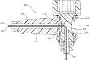
- FIG. 4is a cross sectional view of a swivel elbow connector, according to one embodiment.
- FIG. 5is an exploded view of a swivel elbow connector, according to one embodiment.
- FIG. 6is a cross sectional view of a swivel elbow connector with an integrated retaining ring, according to one embodiment.
- FIG. 7is a close up view of a portion of the swivel elbow connector with an integrated retaining ring of FIG. 6 .
- FIG. 8is a partially exploded cross sectional view of the swivel elbow connector with an integrated retaining ring, of FIGS. 6 and 7 .
- a swivel elbow connectormay include a core with a center cavity. At least one aperture may provide an opening to the center cavity in the core.
- a first interfacemay be mechanically coupled to the core and fluidly coupled with the center cavity in the core.
- a swivel elbow connectormay include a hub that selectively rotates relative to the core and the first interface.
- the hubmay include a sleeve that surrounds the core and a stem with a second interface that forms a port through the lateral surface of the hub.
- the swivel elbow connectormay form a fluid pathway for transferring a fluid through the second interface, the hollow stem, the hub, the plurality of apertures in the core, and the first interface.
- Typical elbow connectorsmay be used to change the angle of an interface, however the rotation required to couple two luer connectors positioned at one or both ends of the elbow may cause the elbow to be positioned at an undesirable angle. Further, a typical elbow connector is rigid and stationary making any connected tubing susceptible to kinks and breaks if pulled.
- a swivel elbow connectormay increase the accessibility of a medical device interface without the detriments of a typical elbow connector.
- a rotatable hubmay allow the angle of the swivel elbow connector to be adjusted to increase accessibility. Further, the rotatable hub may prevent kinks and breaks by rotating when a connected tube is pulled.
- the rotatable hubmay include a sleeve and a stem.
- the sleevemay be a barrel forming a chamber.
- the sleevemay be plastic molded into a hollow cylinder with openings on both ends.
- the stemmay be coupled to a lateral side of the sleeve and in fluid communication with the chamber.
- the stemmay be perpendicular to the sleeve.
- the stemmay protrude off the lateral side at angles other than 90 degrees.
- the chambermay be configured in size and shape to house the core.
- the coremay form a cavity and extend through the sleeve's chamber.
- the cavitymay be in fluid communication with the chamber via one or more apertures in the core.
- the coremay have a plurality of apertures. The apertures may extend through the entire core.
- the coremay be sealed within the sleeve.
- two O-ringsmay fluidly seal the sleeve to the core.
- a fastener and a gripping surfacemay retain the core within the sleeve.
- the fastenermay be a snap-fit retaining ring, a threaded retaining ring, a lock nut, or a bonded joint. In one embodiment, the fastener may be adjusted to make the hub easier or more difficult to rotate.
- the gripping surfacemay be rotatable and mechanically coupled to the core. A user may rotate the core using the gripping surface. The gripping surface may also rotate the first interface coupled to the core. The gripping surface may have an uneven surface to assist in rotating the core. For example, the gripping surface may have a plurality of grip tabs. Alternatively, the gripping surface may have a plurality of grooves.
- Medical tools and devicesmay attach to the first and second interfaces of the swivel elbow connector.
- the first interfacemay be a male luer and the second interface may be a female luer.
- the first interfacemay be a different type than the second interface.
- a valvemay limit dripping and leakage when either interface is disconnected.
- Attached medical tools and devicesmay transfer material through the fluid pathway of the connector.
- materialmay only flow when the stem is in line with an aperture in the core.
- the swivel elbow connectormay selectively rotate between a lock position in which no material may pass and an unlocked position in which material may pass freely.
- the swivel elbow connectormay provide tactile feedback when the position is changed.
- the hub's sleeve and coreare sized and positioned to allow material to surround the core and enter apertures not in line with the stem.
- the swivel elbow connectormay allow for a continuous flow of material regardless of positioning.
- Coupled tois broad enough to refer to any suitable coupling or other form of interaction between two or more entities, including mechanical, fluidic and thermal interaction. Thus, two components may be coupled to each other even though they are not in direct contact with each other.
- attached torefers to interaction between two or more entities which are in direct contact with each other and/or are separated from each other only by a fastener of any suitable variety (e.g., mounting hardware or an adhesive).
- fluidly coupledand “fluid communication” are broad enough to refer to arrangements in which a fluid (e.g., a gas or a liquid) can flow from one element to another element when the elements are in fluid communication with each other.
- a fluide.g., a gas or a liquid
- proximal and distalare opposite directional terms.
- distal end of a device or componentis the end of the component that is furthest from the physician during ordinary use.
- proximal endrefers to the opposite end, or the end nearest the physician during ordinary use.
- FIGS. 1A and 1Bare perspective views of a swivel elbow connector 100 , according to one embodiment.
- the swivel elbow connector 100may include a hub 102 that freely rotates around a core 104 .
- the ability of the hub 102 to rotatemay allow a user to reposition the hub 102 for accessibility of coupling locations or interfaces 110 , 112 described below.
- the hub 102may include a sleeve 106 , a stem 108 , and a first interface 110 .
- the sleeve 106may be a cylinder.
- the stem 108may form a port through a lateral of the sleeve 106 .
- the first interface 110may be located at a proximal end of the stem 108 .
- the sleeve 106 and the stem 108may be hollow and form a first fluid pathway to allow material to pass from the first interface 110 to the sleeve 106 .
- the core 104may extend through the sleeve 106 .
- the core 104may have a second fluid pathway in fluid communication with the first fluid pathway.
- the second fluid pathway in the core 104may direct material from the first fluid pathway through a second interface 112 .
- the core 104may also include a gripping surface 114 .
- a usermay rotate the gripping surface 114 to rotate the entire core 104 . This may allow a user to rotate the core 104 without affecting the hub 102 .
- the second interface 112may be a threaded interface.
- a usermay rotate the gripping surface 114 . Because the hub 102 may rotate freely, the rotation of the core 104 would not affect the hub's positioning.
- the gripping surface 114may include a series of tabs 116 or grooves to improve handling. Additionally, once the core 104 is coupled to a medical tool, the hub 102 may still be free to rotate about the core 104 while still maintaining flow through from the first interface 110 to the second interface 112 (and flow from the second interface 112 to the first interface 110 ).
- the first interface 110may be at an angle relative to the second interface 112 . As shown, the first interface 110 may be perpendicular to the second interface 112 . In alternative embodiments, the angle between the first interface 110 and the second interface 112 may be different. In one embodiment, the stem 108 may be flexible to accommodate a variety of angles.
- the first interface 110 and the second interface 112may connect to a first and a second medical tool.
- the first interface 110may connect to a bone cement injector and the second interface 112 may connect to a cannula.
- the first interface 110 and the second interface 112may be the same type.
- the first interface 110 and the second interface 112may be a male and a female luer.
- swivel elbow connector 100may be an adapter and the first interface 110 and the second interface 112 may be different types.
- a fastener 118may secure the hub 102 to the core 104 .
- the fastener 118may be a snap-fit retaining ring or a threaded retaining ring. The fastener 118 may limit the movement of the hub 102 with respect to the core 104 , allowing the hub 102 to rotate with respect to the core 104 but not translate with respect to the core 104 .
- FIGS. 2A and 2Bare perspective views of a core 200 of a swivel elbow connector, according to one embodiment.
- the core 200 of FIGS. 2A and 2Bis one example of a core 104 that may be used with the swivel elbow connector of FIGS. 1A and 1 B.
- the core 200may include a gripping surface 202 , a junction 204 , and an interface 206 .
- the core 200may be one continuous piece.
- the gripping surface 202 , the junction 204 , and the interface 206may be molded as a single piece or etched from a single block.
- the gripping surface 202 , the junction 204 , and the interface 206may be separate pieces coupled together.
- the gripping surface 202may be attached to the junction 204 , which may be attached to the interface 206 .
- the relative placement of the core 200 elementsmay be different.
- a gripping surfacemay be built into the interface 206 .
- the gripping surface 202may be a knob or handle to rotate the core 200 .
- the core 200may rotate to couple the interface 206 to a mating interface via threads.
- the gripping surface 202may have an uneven surface for additional grip.
- the gripping surface 202may include a plurality of tabs 208 .
- the gripping surface 202may include grooves or divots.
- the core 200may have a fluid passage way 210 .
- the fluid passageway 210may extend from the interface 206 to the junction 204 . Material may enter or exit the fluid passageway 210 via an opening in the interface 206 and apertures 212 in the junction 204 .
- apertures 212accessing the fluid passageway 210 from a variety of angles.
- the apertures 212may be elongated shapes for increased flow while maintaining structural integrity of the junction 204 .
- the apertures 212may include a plurality of smaller holes arranged such that at least one aperture 212 will align with the stem of the hub at any given position.
- the junction 204When assembled, the junction 204 may be enclosed by the swivel elbow connector's hub.
- the junction 204may include hub support members 214 , 216 to couple to the hub.
- the support members 214 , 216may have a similar diameter as the hub's chamber to allow the hub to rotate with little play.
- a portion of the junction 204may have a smaller diameter than the support members 214 , 216 , forming an annular space between the smaller diameter portion of the junction 204 and a hub coupled to the core 200 (see annular space 427 of FIG. 4 ).
- material traveling through the connectormay flow into the annular space and surround the smaller diameter portion and fill all of the apertures 212 and flow through the fluid passageway 210 .
- the direction of flowcould also be reversed, flowing from the passageway 210 to the annular space and out through a portion of a hub coupled to the core 200 .
- an aperturewould have to be in line with a hub's stem to allow material to flow through the fluid pathway.
- FIGS. 3A and 3Bare perspective views of a hub 300 of a swivel elbow connector, according to one embodiment.
- the hub 200 of FIGS. 3A and 3Bis one example of a hub 102 that may be used with the swivel elbow connector of FIGS. 1A and 1B .
- the hub 300may include a sleeve 302 , a stem 304 , and an interface 306 .
- the coremay be one continuous piece.
- the sleeve 302 , the stem 304 , and the interface 306may be molded as a single piece or etched from a single block.
- the gripping surface 202 , the sleeve 302 , the stem 304 , and the interface 306may be separate pieces coupled together.
- the sleeve 302may be made from a rigid plastic, to maintain a cylindrical shape, and the stem 304 may be made of a flexible or semi rigid material to increase accessibility to the interface 306 .
- the cylindrical shape of the sleeve 302may allow the hub 300 to rotate around a core.
- the sleeve 302may be able to rotate an entire 360 degrees.
- the sleeve 302may contain a limiter that limits the degree that the hub 300 can rotate around the core.
- the hub 300may have a fluid passageway 308 .
- the fluid passageway 308may extend from the interface 306 through the stem 304 to the sleeve 302 . Material may enter or exit the fluid passageway 308 via an opening in the interface 306 and an opening in the sleeve 302 .
- FIG. 4is a cross sectional view of a swivel elbow connector 400 , according to one embodiment. This cross sectional view is one example of a cross sectional view of the swivel elbow connector 100 of FIGS. 1A and 1B . As shown in FIG. 4 , a material 406 may travel from a first interface 402 to a second interface 404 through a fluid passageway 408 .
- the material 406may enter the first interface 402 .
- the material 406may be introduced by a medical tool coupled to the first interface 402 . After the material 406 enters the first interface 402 , it may travel through the fluid passageway 408 down a stem 410 to reach a sleeve 412 .
- An annular space 427may be disposed between an inside diameter of the sleeve 412 and an outside diameter of a core 416 disposed within the sleeve 412 .
- the material 406may then enter apertures 414 of a core 416 .
- the material 406may then exit the second interface 404 .
- O-rings 418 , 420may seal the sleeve 412 to prevent the material 406 from leaking from the annular space 427 out of the sleeve 412 .
- FIG. 4depicts the material 406 traveling in one direction
- the swivel elbow connector 400may allow the material 406 to move in either direction, that is from the first interface 402 to the second interface 404 or from the second interface 404 to the first interface 402 .
- a valvemay limit the flow or direction of the material.
- FIG. 5is an exploded view of a swivel elbow connector 500 , according to one embodiment.
- This exploded viewis one example of components that may be used with the swivel elbow connector 100 of FIGS. 1A and 1B or the swivel elbow connector 400 of FIG. 4 .
- the swivel elbow connector 500may be assembled with a core 502 , a hub 504 , two O-rings 506 and 508 , and a snap ring 510 .
- An assemblermay place the O-ring 506 on the core 502 . Grooves 512 and a gripping surface 514 may assist in the O-ring 506 placement.
- An assemblermay then place the hub 504 on the core 502 .
- the hub 504may align with the core 502 such that they are in fluid communication.
- O-rings 506 and 508may fluidly seal the hub 504 to the core 502 .
- the snap ring 510may retain the hub 504
- FIG. 6is a cross sectional view of a swivel elbow connector 600 with an integrated retaining ring 702 , according to one embodiment.
- Various features recited in connection with embodiments illustrated in FIGS. 1-5may be used in connection with the swivel elbow connector 600 and vice versa. Features of each embodiment may be understood as applying analogously to the other embodiments.
- the swivel elbow connector 600may comprise a hub 608 and a core 616 with a gripping surface 613 .
- Materialmay enter the first interface 602 , and travel through a fluid passageway 603 down a stem 610 to reach a sleeve 612 .
- An annular space 627may be disposed between an inside diameter of the sleeve 612 and an outside diameter of a core 616 disposed within the sleeve 612 .
- the materialmay enter apertures 614 of a core 616 , and exit the second interface 604 .
- O-rings 618 , 620may seal the sleeve 612 to prevent the material from leaking from the annular space 627 out of the sleeve 612 .
- the integrated retaining ring 702may couple the hub 608 and a core 616 .
- the integrated retaining ring 702may comprise one or more lock tabs (e.g., lock tab 710 ) coupled to the hub 608 that mate with along a notch 720 on the core 616 . As shown, the notch 720 may be located adjacent or near the gripping surface 613 .
- lock tabse.g., lock tab 710
- FIG. 7is a close up view of a portion 700 of the swivel elbow connector with an integrated retaining ring 702 of FIG. 6 .
- the integrated retaining ring 702may include a lock tab 710 that comprises a sloped interface 712 and a catch 714 .
- the integrated retaining ring 702may have a diameter slightly smaller than the core.
- the sloped interface 712may receive the core, and allow an assembler to push the core through the retaining ring 702 .
- the lock tab 710may flex to accommodate the core.
- the catch 714reaches the slot 720 on the core, the lock tab may resume its original diameter.
- the catch 714may settle into the notch 714 and be retained by the core's sidewall 724 .
- FIG. 8is a partially exploded cross sectional view of the swivel elbow connector 600 with an integrated retaining ring 702 of FIGS. 6 and 7 .
- the integrated retaining ring 702may be coupled to the hub 608 .
- the retaining ring 702may comprise a plurality of locking tabs (e.g., 710 , 820 , 830 ).
- the locking tabs 710 , 820 , and 830may be disconnected from one another to allow each lock tab to flex.
- the lock tabs 710 , 820 , and 830may be configured to catch or latch in the notch 720 of the core 616 .
- the notch 720may be a groove along the entire circumference of the core 616 .
- the notch 720may be a series of groves that must be aligned with the lock tabs 710 , 820 , and 830 .
- An assemblermay then slide the core 616 into the hub 608 .
- the lock tabs 710 , 820 , and 830may flex slightly to allow the core 616 to be pushed through.
- the locking tabs 710 , 820 , and 830may return to their original position, causing them to catch in the notch 720 .
- the locking tabs 710 , 820 , and 830catch they may retain the core.
- the lock tabs 710 , 820 , and 830may limit the movement of the hub 608 with respect to the core 616 , allowing the hub 608 to rotate with respect to the core 616 but not translate with respect to the core 616 .
- Any methods disclosed hereininclude one or more steps or actions for performing the described method.
- the method steps and/or actionsmay be interchanged with one another.
- the order and/or use of specific steps and/or actionsmay be modified.
- sub-routines or only a portion of a method described hereinmay be a separate method within the scope of this disclosure. Stated otherwise, some methods may include only a portion of the steps described in a more detailed method.
Landscapes
- Health & Medical Sciences (AREA)
- Heart & Thoracic Surgery (AREA)
- Engineering & Computer Science (AREA)
- Hematology (AREA)
- Anesthesiology (AREA)
- Biomedical Technology (AREA)
- Pulmonology (AREA)
- Life Sciences & Earth Sciences (AREA)
- Animal Behavior & Ethology (AREA)
- General Health & Medical Sciences (AREA)
- Public Health (AREA)
- Veterinary Medicine (AREA)
- Infusion, Injection, And Reservoir Apparatuses (AREA)
- General Engineering & Computer Science (AREA)
- Mechanical Engineering (AREA)
Abstract
Description
Claims (19)
Priority Applications (1)
| Application Number | Priority Date | Filing Date | Title |
|---|---|---|---|
| US15/812,580US11052237B2 (en) | 2016-11-22 | 2017-11-14 | Swivel hub |
Applications Claiming Priority (2)
| Application Number | Priority Date | Filing Date | Title |
|---|---|---|---|
| US201662425459P | 2016-11-22 | 2016-11-22 | |
| US15/812,580US11052237B2 (en) | 2016-11-22 | 2017-11-14 | Swivel hub |
Publications (2)
| Publication Number | Publication Date |
|---|---|
| US20180140821A1 US20180140821A1 (en) | 2018-05-24 |
| US11052237B2true US11052237B2 (en) | 2021-07-06 |
Family
ID=62144171
Family Applications (1)
| Application Number | Title | Priority Date | Filing Date |
|---|---|---|---|
| US15/812,580ActiveUS11052237B2 (en) | 2016-11-22 | 2017-11-14 | Swivel hub |
Country Status (3)
| Country | Link |
|---|---|
| US (1) | US11052237B2 (en) |
| EP (1) | EP3544669A4 (en) |
| WO (1) | WO2018097992A2 (en) |
Families Citing this family (5)
| Publication number | Priority date | Publication date | Assignee | Title |
|---|---|---|---|---|
| US20190275312A1 (en)* | 2018-03-12 | 2019-09-12 | Np Medical Inc. | Vascular access site management system |
| CN109224285B (en)* | 2018-07-12 | 2021-03-05 | 合肥市第二人民医院 | Negative pressure drainage tube connecting device |
| US11291801B2 (en) | 2020-01-31 | 2022-04-05 | Np Medical Inc. | Patient access site securement system |
| CN116669807A (en)* | 2020-11-30 | 2023-08-29 | 直观外科手术操作公司 | Medical device inflation adapter |
| GB2620436B (en)* | 2022-07-08 | 2024-12-04 | Watson Marlow Ltd | Aseptic connector |
Citations (137)
| Publication number | Priority date | Publication date | Assignee | Title |
|---|---|---|---|---|
| US3125360A (en)* | 1964-03-17 | Fluid conduit coupler | ||
| US3140623A (en) | 1961-08-29 | 1964-07-14 | Pendleton Tool Ind Inc | Predetermined torque release wrench |
| US3147015A (en)* | 1960-03-24 | 1964-09-01 | Weatherhead Co | Seal ring |
| US3244439A (en)* | 1964-05-07 | 1966-04-05 | Hydralink Corp | Reusable swivel hose coupling |
| US3384394A (en)* | 1967-02-23 | 1968-05-21 | Kent Moore Organization Inc | Connector for a pipe threaded port |
| US4411266A (en) | 1980-09-24 | 1983-10-25 | Cosman Eric R | Thermocouple radio frequency lesion electrode |
| US4456017A (en) | 1982-11-22 | 1984-06-26 | Cordis Corporation | Coil spring guide with deflectable tip |
| US4476861A (en) | 1979-11-06 | 1984-10-16 | Christos Dimakos | Instrument for removal of a bone cement tube in an artificial femur head reimplantation |
| US4595006A (en) | 1982-08-16 | 1986-06-17 | Burke Dennis W | Apparatus for cemented implantation of prostheses |
| US4672998A (en) | 1985-04-09 | 1987-06-16 | San Diego Gas & Electric | Hydraulic swivel connector |
| US5103804A (en) | 1990-07-03 | 1992-04-14 | Boston Scientific Corporation | Expandable tip hemostatic probes and the like |
| WO1993004634A1 (en) | 1991-09-12 | 1993-03-18 | Surgical Dynamics, Inc. | Bendable dissectomy probe and steerable cannula |
| US5282821A (en) | 1993-01-26 | 1994-02-01 | Donahue John R | Adjustable surgical instrument |
| US5284128A (en) | 1992-01-24 | 1994-02-08 | Applied Medical Resources Corporation | Surgical manipulator |
| US5322505A (en) | 1990-02-07 | 1994-06-21 | Smith & Nephew Dyonics, Inc. | Surgical instrument |
| US5389073A (en) | 1992-12-01 | 1995-02-14 | Cardiac Pathways Corporation | Steerable catheter with adjustable bend location |
| US5437636A (en) | 1992-07-06 | 1995-08-01 | Catheter Imaging Systems | Steerable catheter with fiberoptic scope inserting means |
| US5449351A (en) | 1993-09-09 | 1995-09-12 | Zohmann; Walter A. | Atraumatic needle for lumbar puncture |
| US5458597A (en) | 1993-11-08 | 1995-10-17 | Zomed International | Device for treating cancer and non-malignant tumors and methods |
| US5571088A (en) | 1993-07-01 | 1996-11-05 | Boston Scientific Corporation | Ablation catheters |
| US5599346A (en) | 1993-11-08 | 1997-02-04 | Zomed International, Inc. | RF treatment system |
| WO1997003611A1 (en) | 1995-07-18 | 1997-02-06 | Edwards, Garland, U. | Flexible shaft |
| US5620467A (en) | 1995-10-10 | 1997-04-15 | Incontrol, Inc. | Implantable atrial defibrillator having cardioverting output voltage limiting for simulating larger storage capacitors |
| US5620447A (en) | 1993-01-29 | 1997-04-15 | Smith & Nephew Dyonics Inc. | Surgical instrument |
| US5628771A (en) | 1993-05-12 | 1997-05-13 | Olympus Optical Co., Ltd. | Electromagnetic-wave thermatological device |
| US5637090A (en) | 1993-10-15 | 1997-06-10 | Ep Technologies, Inc. | Multiple electrode element for mapping and ablating heart tissue |
| US5662680A (en) | 1991-10-18 | 1997-09-02 | Desai; Ashvin H. | Endoscopic surgical instrument |
| US5695513A (en) | 1996-03-01 | 1997-12-09 | Metagen, Llc | Flexible cutting tool and methods for its use |
| US5697536A (en) | 1992-01-07 | 1997-12-16 | Arthrocare Corporation | System and method for electrosurgical cutting and ablation |
| US5810804A (en) | 1995-08-15 | 1998-09-22 | Rita Medical Systems | Multiple antenna ablation apparatus and method with cooling element |
| US5833632A (en) | 1995-12-07 | 1998-11-10 | Sarcos, Inc. | Hollow guide wire apparatus catheters |
| US5851212A (en) | 1997-06-11 | 1998-12-22 | Endius Incorporated | Surgical instrument |
| US5855577A (en) | 1996-09-17 | 1999-01-05 | Eclipse Surgical Technologies, Inc. | Bow shaped catheter |
| US5891027A (en) | 1996-10-21 | 1999-04-06 | Irvine Biomedical, Inc. | Cardiovascular catheter system with an inflatable soft tip |
| US5902251A (en) | 1996-05-06 | 1999-05-11 | Vanhooydonk; Neil C. | Transcervical intrauterine applicator for intrauterine hyperthermia |
| US5921956A (en) | 1997-09-24 | 1999-07-13 | Smith & Nephew, Inc. | Surgical instrument |
| US5928239A (en) | 1998-03-16 | 1999-07-27 | University Of Washington | Percutaneous surgical cavitation device and method |
| US5944715A (en) | 1996-06-20 | 1999-08-31 | Gyrus Medical Limited | Electrosurgical instrument |
| US5947964A (en) | 1995-03-03 | 1999-09-07 | Neothermia Corporation | Methods and apparatus for therapeutic cauterization of predetermined volumes of biological tissue |
| US6064902A (en) | 1998-04-16 | 2000-05-16 | C.R. Bard, Inc. | Pulmonary vein ablation catheter |
| US6073051A (en) | 1996-08-13 | 2000-06-06 | Oratec Interventions, Inc. | Apparatus for treating intervertebal discs with electromagnetic energy |
| US6106524A (en) | 1995-03-03 | 2000-08-22 | Neothermia Corporation | Methods and apparatus for therapeutic cauterization of predetermined volumes of biological tissue |
| US6123702A (en) | 1998-09-10 | 2000-09-26 | Scimed Life Systems, Inc. | Systems and methods for controlling power in an electrosurgical probe |
| US6135999A (en) | 1997-02-12 | 2000-10-24 | Oratec Internationals, Inc. | Concave probe for arthroscopic surgery |
| US6231615B1 (en) | 1997-10-14 | 2001-05-15 | Parallax Medical, Inc. | Enhanced visibility materials for implantation in hard tissue |
| US20010003312A1 (en)* | 1995-11-17 | 2001-06-14 | Richard V. Spiegel | Transmission fluid cooler-bypass unit for a transmission fluid cooling system |
| US6280441B1 (en) | 1997-12-15 | 2001-08-28 | Sherwood Services Ag | Apparatus and method for RF lesioning |
| US20020026197A1 (en) | 2000-08-11 | 2002-02-28 | Foley Kevin T. | Surgical instrumentation and method for treatment of the spine |
| US6409722B1 (en) | 1998-07-07 | 2002-06-25 | Medtronic, Inc. | Apparatus and method for creating, maintaining, and controlling a virtual electrode used for the ablation of tissue |
| US6440138B1 (en) | 1998-04-06 | 2002-08-27 | Kyphon Inc. | Structures and methods for creating cavities in interior body regions |
| US6447506B1 (en) | 1993-10-15 | 2002-09-10 | Ep Technologies, Inc. | Systems and methods for creating long, thin lesions in body tissue |
| US20020133148A1 (en) | 2001-01-11 | 2002-09-19 | Daniel Steven A. | Bone-treatment instrument and method |
| US6464683B1 (en) | 1997-04-25 | 2002-10-15 | Schneider (Usa) Inc. | Trilayer, extruded medical tubing and medical devices incorporating such tubbing |
| US6478793B1 (en) | 1999-06-11 | 2002-11-12 | Sherwood Services Ag | Ablation treatment of bone metastases |
| US20030014094A1 (en) | 2001-07-13 | 2003-01-16 | Radiant Medical, Inc. | Catheter system with on-board temperature probe |
| US6575969B1 (en) | 1995-05-04 | 2003-06-10 | Sherwood Services Ag | Cool-tip radiofrequency thermosurgery electrode system for tumor ablation |
| US20030130664A1 (en) | 1998-08-14 | 2003-07-10 | Kyphon Inc. | Systems and methods for treating vertebral bodies |
| US6592559B1 (en) | 1998-12-09 | 2003-07-15 | Cook Incorporated | Hollow, curved, superlastic medical needle |
| US6602248B1 (en) | 1995-06-07 | 2003-08-05 | Arthro Care Corp. | Methods for repairing damaged intervertebral discs |
| US6615830B1 (en) | 1997-02-27 | 2003-09-09 | Respironics, Inc. | Swivel device utilizing bearing clearance to allow carbon dioxide laden exhaust |
| US20030212395A1 (en) | 2000-05-12 | 2003-11-13 | Arthrocare Corporation | Systems and methods for electrosurgery |
| US20030212394A1 (en) | 2001-05-10 | 2003-11-13 | Rob Pearson | Tissue ablation apparatus and method |
| WO2003101308A1 (en) | 2002-06-04 | 2003-12-11 | Office Of Technology Licensing Stanford University | Device and method for rapid aspiration and collection of body tissue from within an enclosed body space |
| US20040087936A1 (en) | 2000-11-16 | 2004-05-06 | Barrx, Inc. | System and method for treating abnormal tissue in an organ having a layered tissue structure |
| JP2004242936A (en) | 2003-02-14 | 2004-09-02 | Terumo Corp | Puncture needle |
| US20040202505A1 (en) | 2003-04-14 | 2004-10-14 | Pagliai Ferro Francesco | Two-piece, high performance swivel connector |
| US20040212193A1 (en)* | 2002-10-08 | 2004-10-28 | Johnstone Ian David | Connector |
| US20050055030A1 (en) | 2003-09-05 | 2005-03-10 | Falahee Mark H. | Cement/biologics inserter and method for bone-fastener fixation augmentation |
| US20050090852A1 (en) | 2000-04-07 | 2005-04-28 | Kyphon Inc. | Insertion devices and method of use |
| US20050177210A1 (en) | 2002-03-05 | 2005-08-11 | Baylis Medical Company Inc. | Electrosurgical tissue treatment method |
| US20050216018A1 (en) | 2004-03-29 | 2005-09-29 | Sennett Andrew R | Orthopedic surgery access devices |
| US20060025763A1 (en) | 2000-08-21 | 2006-02-02 | Dale Nelson | Ablation catheter with cooled linear electrode |
| US7022133B2 (en) | 1997-11-14 | 2006-04-04 | Scimed Life Systems, Inc. | Multi-sheath delivery catheter |
| US20060085009A1 (en) | 2004-08-09 | 2006-04-20 | Csaba Truckai | Implants and methods for treating bone |
| US20060200121A1 (en) | 2005-03-03 | 2006-09-07 | Mowery Thomas M | Navigable, multi-positional and variable tissue ablation apparatus and methods |
| US20060264819A1 (en) | 2005-05-05 | 2006-11-23 | Brian Fischer | Deflectable catheter steering and locking system |
| CN2841051Y (en) | 2005-08-24 | 2006-11-29 | 汤枧根 | The umbrella shape therapeutic electrode |
| US7156843B2 (en) | 2003-09-08 | 2007-01-02 | Medtronic, Inc. | Irrigated focal ablation tip |
| US7156845B2 (en) | 1998-07-07 | 2007-01-02 | Medtronic, Inc. | Method and apparatus for creating a bi-polar virtual electrode used for the ablation of tissue |
| US20070006692A1 (en) | 2005-07-11 | 2007-01-11 | Phan Christopher U | Torque limiting device |
| US7186234B2 (en) | 1995-11-22 | 2007-03-06 | Arthrocare Corporation | Electrosurgical apparatus and methods for treatment and removal of tissue |
| US20070055281A1 (en) | 1994-01-26 | 2007-03-08 | Kyphon Inc. | Methods for treating a fractured and/or diseased vertebral body by incremental introduction of bone filling material |
| WO2007036815A2 (en) | 2005-09-28 | 2007-04-05 | Depuy Spine, Inc. | Cannula for injecting material into bone |
| US20070156130A1 (en) | 2005-12-29 | 2007-07-05 | Boston Scientific Scimed, Inc. | Low-profile, expanding single needle ablation probe |
| US7267683B2 (en) | 1996-08-13 | 2007-09-11 | Oratec Interventions, Inc. | Method for treating intervertebral discs |
| US20070260257A1 (en) | 2005-07-11 | 2007-11-08 | Phan Christopher U | Surgical device having interchangeable components and methods of use |
| US20070282305A1 (en) | 2004-04-21 | 2007-12-06 | Eric Goldfarb | Endoscopic methods and devices for transnasal procedures |
| US20080012294A1 (en) | 2005-10-18 | 2008-01-17 | Chia-Chun Cheng | Pipe Connector |
| US20080033422A1 (en) | 2006-08-04 | 2008-02-07 | Turner Paul F | Microwave applicator with margin temperature sensing element |
| US20080058821A1 (en) | 2004-02-04 | 2008-03-06 | Tissuelink Medical, Inc. | Fluid-assisted medical devices and methods |
| WO2008076330A1 (en) | 2006-12-15 | 2008-06-26 | Soteira, Inc. | Drills and methods for vertebrostenting |
| WO2008084479A2 (en) | 2007-01-09 | 2008-07-17 | Nonlinear Technologies Ltd. | Devices for forming curved or closed-loop structures |
| US20080183165A1 (en) | 2007-01-31 | 2008-07-31 | Steven Paul Buysse | Thermal Feedback Systems and Methods of Using the Same |
| US20080183265A1 (en) | 2007-01-30 | 2008-07-31 | Cardiac Pacemakers, Inc. | Transvascular lead with proximal force relief |
| US20080208255A1 (en) | 2004-08-11 | 2008-08-28 | Tzony Siegal | Devices For Introduction Into A Body Via A Substantially Straight Conduit To Form A Predefined Curved Configuration, And Methods Employing Same |
| US20080249525A1 (en) | 2005-11-08 | 2008-10-09 | U & I Corporation | Radio Frequency Ablation Electrode for Selected Tissue Removal |
| US20090146416A1 (en) | 2007-12-07 | 2009-06-11 | Chung-Chih Wei | Universal Quick Connection Unit for Connecting Pipe to Hydraulic or Pneumatic Tool |
| US7569054B2 (en) | 1988-06-13 | 2009-08-04 | Warsaw Orthopedic, Inc. | Tubular member having a passage and opposed bone contacting extensions |
| US20090264892A1 (en) | 2003-06-17 | 2009-10-22 | Depuy Spine, Inc. | Methods, Materials and Apparatus for Treating Bone or Other Tissue |
| US20090264862A1 (en) | 2008-04-16 | 2009-10-22 | Medtronic, Inc. | Medical delivery device construction |
| US7625364B2 (en) | 2003-05-27 | 2009-12-01 | Cardia, Inc. | Flexible center connection for occlusion device |
| US20090293687A1 (en) | 2008-06-02 | 2009-12-03 | Eca Medical Instruments | Torque-limiting device |
| US20090299282A1 (en) | 2007-11-16 | 2009-12-03 | Osseon Therapeutics, Inc. | Steerable vertebroplasty system with a plurality of cavity creation elements |
| US20100082033A1 (en) | 2008-09-30 | 2010-04-01 | Dfine, Inc. | System for use in treatment of vertebral fractures |
| US20100152724A1 (en) | 2008-12-12 | 2010-06-17 | Arthrocare Corporation | Systems and methods for limiting joint temperature |
| WO2010081187A1 (en) | 2009-01-15 | 2010-07-22 | Cathrx Ltd | Steerable stylet |
| US20100211076A1 (en) | 2008-10-13 | 2010-08-19 | Dfine, Inc. | Systems for treating a vertebral body |
| US7824403B2 (en) | 1996-10-22 | 2010-11-02 | St. Jude Medical, Atrial Fibrillation Division, Inc. | Methods and devices for ablation |
| WO2010135606A1 (en) | 2009-05-20 | 2010-11-25 | Osseon Therapeutics, Inc. | Steerable curvable vertebroplasty drill |
| WO2010135602A1 (en) | 2009-05-20 | 2010-11-25 | Osseon Therapeutics, Inc. | Steerable curvable ablation catheter for vertebroplasty |
| US20110034884A9 (en) | 2002-09-30 | 2011-02-10 | Relievant Medsystems, Inc. | Systems and methods for navigating an instrument through bone |
| US7905884B2 (en) | 2006-04-27 | 2011-03-15 | Warsaw Orthopedic, Inc. | Method for use of dilating stylet and cannula |
| US20110098701A1 (en) | 2005-07-22 | 2011-04-28 | Boston Scientific Scimed, Inc. | Bipolar radio frequency ablation device with retractable insulator and method of using same |
| US20110160737A1 (en) | 2008-07-15 | 2011-06-30 | Thomas Steffen | Bone cement injection device |
| US20110251615A1 (en) | 2010-04-08 | 2011-10-13 | Dfine, Inc. | System for use in treatment of vertebral fractures |
| WO2011137377A1 (en) | 2010-04-29 | 2011-11-03 | Dfine, Inc. | System for use in treatment of vertebral fractures |
| WO2011137357A1 (en) | 2010-04-29 | 2011-11-03 | Dfine, Inc. | System for use in treatment of vertebral fractures |
| US20110297757A1 (en) | 2010-06-08 | 2011-12-08 | Schmuckle Darrin I | Swivel Adapter for an Irrigation Valve |
| US20110301590A1 (en) | 2010-06-03 | 2011-12-08 | Tyco Healthcare Group Lp | Specific Absorption Rate Measurement and Energy-Delivery Device Characterization Using Image Analysis |
| US20120065543A1 (en) | 2009-05-29 | 2012-03-15 | Promex Technologies, Llc | Flexible biopsy needle |
| US20120130381A1 (en) | 2010-11-22 | 2012-05-24 | Dfine, Inc. | System for use in treatment of vertebral fractures |
| US20120191037A1 (en)* | 2011-01-25 | 2012-07-26 | Thermedx, Llc | Tube connector with integrated relief valve |
| US8246627B2 (en) | 2008-08-07 | 2012-08-21 | Stryker Corporation | Cement delivery device for introducing cement into tissue, the device having a cavity creator |
| US20120239049A1 (en) | 2005-09-01 | 2012-09-20 | Dfine, Inc. | Systems for delivering bone fill material |
| US20120330180A1 (en) | 2010-01-07 | 2012-12-27 | Relievant Medsystems, Inc. | Vertebral bone channeling systems |
| US20130072941A1 (en) | 2011-09-16 | 2013-03-21 | Francisca Tan-Malecki | Cement Injector and Cement Injector Connectors, and Bone Cement Injector Assembly |
| US20130174918A1 (en)* | 2010-09-08 | 2013-07-11 | Airbus Operations Sas | Bleeding System |
| US20130231654A1 (en) | 2010-04-29 | 2013-09-05 | Dfine, Inc. | System for use in treatment of vertebral fractures |
| WO2013147990A1 (en) | 2012-03-27 | 2013-10-03 | Dfine, Inc. | Methods and systems for use in controlling tissue ablation volume by temperature monitoring |
| US8583260B2 (en) | 2004-12-28 | 2013-11-12 | St. Jude Medical, Atrial Fibrillation Division, Inc. | Long travel steerable catheter actuator |
| US20130331692A1 (en)* | 2011-02-25 | 2013-12-12 | Terumo Kabushiki Kaisha | Medical connector |
| US20140163566A1 (en) | 2012-12-12 | 2014-06-12 | Dfine, Inc. | Devices, methods and systems for affixing an access device to a vertebral body for the insertion of bone cement |
| US20150216594A1 (en) | 2008-01-31 | 2015-08-06 | Covidien Lp | Articulating ablation device and method |
| US20150297246A1 (en) | 2012-11-05 | 2015-10-22 | Relievant Medsystems, Inc. | Systems and methods for creating curved paths through bone and modulating nerves within the bone |
| US20160008639A1 (en) | 2013-03-01 | 2016-01-14 | Draeger Safety Uk Limited | Valve assembly |
| WO2016027190A1 (en) | 2014-08-20 | 2016-02-25 | Tecres S.P.A. | Device for supplying fluid substances in the body of a patient |
| US20160228131A1 (en) | 2013-10-15 | 2016-08-11 | Stryker Corporation | Device for creating a void space in a living tissue, the device including a handle with a control knob that can be set regardless of the orientation of the handle |
Family Cites Families (2)
| Publication number | Priority date | Publication date | Assignee | Title |
|---|---|---|---|---|
| US2459643A (en)* | 1945-04-21 | 1949-01-18 | Parker Appliance Co | Swivel coupling |
| US9050909B2 (en)* | 2009-02-24 | 2015-06-09 | Brose Fahrzeugteile Gmbh & Co. Kg, Coburg | Motor vehicle seat |
- 2017
- 2017-11-14WOPCT/US2017/061560patent/WO2018097992A2/ennot_activeCeased
- 2017-11-14USUS15/812,580patent/US11052237B2/enactiveActive
- 2017-11-14EPEP17873790.4Apatent/EP3544669A4/ennot_activeWithdrawn
Patent Citations (168)
| Publication number | Priority date | Publication date | Assignee | Title |
|---|---|---|---|---|
| US3125360A (en)* | 1964-03-17 | Fluid conduit coupler | ||
| US3147015A (en)* | 1960-03-24 | 1964-09-01 | Weatherhead Co | Seal ring |
| US3140623A (en) | 1961-08-29 | 1964-07-14 | Pendleton Tool Ind Inc | Predetermined torque release wrench |
| US3244439A (en)* | 1964-05-07 | 1966-04-05 | Hydralink Corp | Reusable swivel hose coupling |
| US3384394A (en)* | 1967-02-23 | 1968-05-21 | Kent Moore Organization Inc | Connector for a pipe threaded port |
| US4476861A (en) | 1979-11-06 | 1984-10-16 | Christos Dimakos | Instrument for removal of a bone cement tube in an artificial femur head reimplantation |
| US4411266A (en) | 1980-09-24 | 1983-10-25 | Cosman Eric R | Thermocouple radio frequency lesion electrode |
| US4595006A (en) | 1982-08-16 | 1986-06-17 | Burke Dennis W | Apparatus for cemented implantation of prostheses |
| US4456017A (en) | 1982-11-22 | 1984-06-26 | Cordis Corporation | Coil spring guide with deflectable tip |
| US4672998A (en) | 1985-04-09 | 1987-06-16 | San Diego Gas & Electric | Hydraulic swivel connector |
| US7569054B2 (en) | 1988-06-13 | 2009-08-04 | Warsaw Orthopedic, Inc. | Tubular member having a passage and opposed bone contacting extensions |
| US5322505A (en) | 1990-02-07 | 1994-06-21 | Smith & Nephew Dyonics, Inc. | Surgical instrument |
| US5103804A (en) | 1990-07-03 | 1992-04-14 | Boston Scientific Corporation | Expandable tip hemostatic probes and the like |
| WO1993004634A1 (en) | 1991-09-12 | 1993-03-18 | Surgical Dynamics, Inc. | Bendable dissectomy probe and steerable cannula |
| US5662680A (en) | 1991-10-18 | 1997-09-02 | Desai; Ashvin H. | Endoscopic surgical instrument |
| US5697536A (en) | 1992-01-07 | 1997-12-16 | Arthrocare Corporation | System and method for electrosurgical cutting and ablation |
| US5284128A (en) | 1992-01-24 | 1994-02-08 | Applied Medical Resources Corporation | Surgical manipulator |
| US5437636A (en) | 1992-07-06 | 1995-08-01 | Catheter Imaging Systems | Steerable catheter with fiberoptic scope inserting means |
| US5389073A (en) | 1992-12-01 | 1995-02-14 | Cardiac Pathways Corporation | Steerable catheter with adjustable bend location |
| US5282821A (en) | 1993-01-26 | 1994-02-01 | Donahue John R | Adjustable surgical instrument |
| US5620447A (en) | 1993-01-29 | 1997-04-15 | Smith & Nephew Dyonics Inc. | Surgical instrument |
| US5628771A (en) | 1993-05-12 | 1997-05-13 | Olympus Optical Co., Ltd. | Electromagnetic-wave thermatological device |
| US5571088A (en) | 1993-07-01 | 1996-11-05 | Boston Scientific Corporation | Ablation catheters |
| US5449351A (en) | 1993-09-09 | 1995-09-12 | Zohmann; Walter A. | Atraumatic needle for lumbar puncture |
| US5637090A (en) | 1993-10-15 | 1997-06-10 | Ep Technologies, Inc. | Multiple electrode element for mapping and ablating heart tissue |
| US6447506B1 (en) | 1993-10-15 | 2002-09-10 | Ep Technologies, Inc. | Systems and methods for creating long, thin lesions in body tissue |
| US5458597A (en) | 1993-11-08 | 1995-10-17 | Zomed International | Device for treating cancer and non-malignant tumors and methods |
| US5599346A (en) | 1993-11-08 | 1997-02-04 | Zomed International, Inc. | RF treatment system |
| US20070055281A1 (en) | 1994-01-26 | 2007-03-08 | Kyphon Inc. | Methods for treating a fractured and/or diseased vertebral body by incremental introduction of bone filling material |
| US5947964A (en) | 1995-03-03 | 1999-09-07 | Neothermia Corporation | Methods and apparatus for therapeutic cauterization of predetermined volumes of biological tissue |
| US6106524A (en) | 1995-03-03 | 2000-08-22 | Neothermia Corporation | Methods and apparatus for therapeutic cauterization of predetermined volumes of biological tissue |
| US6575969B1 (en) | 1995-05-04 | 2003-06-10 | Sherwood Services Ag | Cool-tip radiofrequency thermosurgery electrode system for tumor ablation |
| US6602248B1 (en) | 1995-06-07 | 2003-08-05 | Arthro Care Corp. | Methods for repairing damaged intervertebral discs |
| WO1997003611A1 (en) | 1995-07-18 | 1997-02-06 | Edwards, Garland, U. | Flexible shaft |
| US5810804A (en) | 1995-08-15 | 1998-09-22 | Rita Medical Systems | Multiple antenna ablation apparatus and method with cooling element |
| US5620467A (en) | 1995-10-10 | 1997-04-15 | Incontrol, Inc. | Implantable atrial defibrillator having cardioverting output voltage limiting for simulating larger storage capacitors |
| US20010003312A1 (en)* | 1995-11-17 | 2001-06-14 | Richard V. Spiegel | Transmission fluid cooler-bypass unit for a transmission fluid cooling system |
| US7270661B2 (en) | 1995-11-22 | 2007-09-18 | Arthocare Corporation | Electrosurgical apparatus and methods for treatment and removal of tissue |
| US7186234B2 (en) | 1995-11-22 | 2007-03-06 | Arthrocare Corporation | Electrosurgical apparatus and methods for treatment and removal of tissue |
| US5833632A (en) | 1995-12-07 | 1998-11-10 | Sarcos, Inc. | Hollow guide wire apparatus catheters |
| US5695513A (en) | 1996-03-01 | 1997-12-09 | Metagen, Llc | Flexible cutting tool and methods for its use |
| US5902251A (en) | 1996-05-06 | 1999-05-11 | Vanhooydonk; Neil C. | Transcervical intrauterine applicator for intrauterine hyperthermia |
| US5944715A (en) | 1996-06-20 | 1999-08-31 | Gyrus Medical Limited | Electrosurgical instrument |
| US6073051A (en) | 1996-08-13 | 2000-06-06 | Oratec Interventions, Inc. | Apparatus for treating intervertebal discs with electromagnetic energy |
| US7267683B2 (en) | 1996-08-13 | 2007-09-11 | Oratec Interventions, Inc. | Method for treating intervertebral discs |
| US5855577A (en) | 1996-09-17 | 1999-01-05 | Eclipse Surgical Technologies, Inc. | Bow shaped catheter |
| US5891027A (en) | 1996-10-21 | 1999-04-06 | Irvine Biomedical, Inc. | Cardiovascular catheter system with an inflatable soft tip |
| US7824403B2 (en) | 1996-10-22 | 2010-11-02 | St. Jude Medical, Atrial Fibrillation Division, Inc. | Methods and devices for ablation |
| US6135999A (en) | 1997-02-12 | 2000-10-24 | Oratec Internationals, Inc. | Concave probe for arthroscopic surgery |
| US6615830B1 (en) | 1997-02-27 | 2003-09-09 | Respironics, Inc. | Swivel device utilizing bearing clearance to allow carbon dioxide laden exhaust |
| US6464683B1 (en) | 1997-04-25 | 2002-10-15 | Schneider (Usa) Inc. | Trilayer, extruded medical tubing and medical devices incorporating such tubbing |
| US5851212A (en) | 1997-06-11 | 1998-12-22 | Endius Incorporated | Surgical instrument |
| US5921956A (en) | 1997-09-24 | 1999-07-13 | Smith & Nephew, Inc. | Surgical instrument |
| US6231615B1 (en) | 1997-10-14 | 2001-05-15 | Parallax Medical, Inc. | Enhanced visibility materials for implantation in hard tissue |
| US7022133B2 (en) | 1997-11-14 | 2006-04-04 | Scimed Life Systems, Inc. | Multi-sheath delivery catheter |
| US6280441B1 (en) | 1997-12-15 | 2001-08-28 | Sherwood Services Ag | Apparatus and method for RF lesioning |
| US5928239A (en) | 1998-03-16 | 1999-07-27 | University Of Washington | Percutaneous surgical cavitation device and method |
| US6863672B2 (en) | 1998-04-06 | 2005-03-08 | Kyphon Inc. | Structures and methods for creating cavities in interior body regions |
| US6440138B1 (en) | 1998-04-06 | 2002-08-27 | Kyphon Inc. | Structures and methods for creating cavities in interior body regions |
| US6064902A (en) | 1998-04-16 | 2000-05-16 | C.R. Bard, Inc. | Pulmonary vein ablation catheter |
| US7156845B2 (en) | 1998-07-07 | 2007-01-02 | Medtronic, Inc. | Method and apparatus for creating a bi-polar virtual electrode used for the ablation of tissue |
| US6409722B1 (en) | 1998-07-07 | 2002-06-25 | Medtronic, Inc. | Apparatus and method for creating, maintaining, and controlling a virtual electrode used for the ablation of tissue |
| US20030130664A1 (en) | 1998-08-14 | 2003-07-10 | Kyphon Inc. | Systems and methods for treating vertebral bodies |
| US6123702A (en) | 1998-09-10 | 2000-09-26 | Scimed Life Systems, Inc. | Systems and methods for controlling power in an electrosurgical probe |
| US6592559B1 (en) | 1998-12-09 | 2003-07-15 | Cook Incorporated | Hollow, curved, superlastic medical needle |
| US6478793B1 (en) | 1999-06-11 | 2002-11-12 | Sherwood Services Ag | Ablation treatment of bone metastases |
| US7480533B2 (en) | 1999-06-11 | 2009-01-20 | Covidien Ag | Ablation treatment of bone metastases |
| US6881214B2 (en) | 1999-06-11 | 2005-04-19 | Sherwood Services Ag | Ablation treatment of bone metastases |
| US20050090852A1 (en) | 2000-04-07 | 2005-04-28 | Kyphon Inc. | Insertion devices and method of use |
| US20030212395A1 (en) | 2000-05-12 | 2003-11-13 | Arthrocare Corporation | Systems and methods for electrosurgery |
| US20080004615A1 (en) | 2000-05-12 | 2008-01-03 | Arthrocare Corporation | Systems and methods for electrosurgical spine surgery |
| US20020026197A1 (en) | 2000-08-11 | 2002-02-28 | Foley Kevin T. | Surgical instrumentation and method for treatment of the spine |
| US20060025763A1 (en) | 2000-08-21 | 2006-02-02 | Dale Nelson | Ablation catheter with cooled linear electrode |
| US20040087936A1 (en) | 2000-11-16 | 2004-05-06 | Barrx, Inc. | System and method for treating abnormal tissue in an organ having a layered tissue structure |
| US6622731B2 (en) | 2001-01-11 | 2003-09-23 | Rita Medical Systems, Inc. | Bone-treatment instrument and method |
| US7108696B2 (en) | 2001-01-11 | 2006-09-19 | Rita Medical Systems, Inc. | Bone-treatment instrument and method |
| US20020133148A1 (en) | 2001-01-11 | 2002-09-19 | Daniel Steven A. | Bone-treatment instrument and method |
| US20030212394A1 (en) | 2001-05-10 | 2003-11-13 | Rob Pearson | Tissue ablation apparatus and method |
| US20030014094A1 (en) | 2001-07-13 | 2003-01-16 | Radiant Medical, Inc. | Catheter system with on-board temperature probe |
| US20050177210A1 (en) | 2002-03-05 | 2005-08-11 | Baylis Medical Company Inc. | Electrosurgical tissue treatment method |
| WO2003101308A1 (en) | 2002-06-04 | 2003-12-11 | Office Of Technology Licensing Stanford University | Device and method for rapid aspiration and collection of body tissue from within an enclosed body space |
| US20110034884A9 (en) | 2002-09-30 | 2011-02-10 | Relievant Medsystems, Inc. | Systems and methods for navigating an instrument through bone |
| US20040212193A1 (en)* | 2002-10-08 | 2004-10-28 | Johnstone Ian David | Connector |
| JP2004242936A (en) | 2003-02-14 | 2004-09-02 | Terumo Corp | Puncture needle |
| US20040202505A1 (en) | 2003-04-14 | 2004-10-14 | Pagliai Ferro Francesco | Two-piece, high performance swivel connector |
| US7625364B2 (en) | 2003-05-27 | 2009-12-01 | Cardia, Inc. | Flexible center connection for occlusion device |
| US20090264892A1 (en) | 2003-06-17 | 2009-10-22 | Depuy Spine, Inc. | Methods, Materials and Apparatus for Treating Bone or Other Tissue |
| US20050055030A1 (en) | 2003-09-05 | 2005-03-10 | Falahee Mark H. | Cement/biologics inserter and method for bone-fastener fixation augmentation |
| US7156843B2 (en) | 2003-09-08 | 2007-01-02 | Medtronic, Inc. | Irrigated focal ablation tip |
| US20080058821A1 (en) | 2004-02-04 | 2008-03-06 | Tissuelink Medical, Inc. | Fluid-assisted medical devices and methods |
| US20050216018A1 (en) | 2004-03-29 | 2005-09-29 | Sennett Andrew R | Orthopedic surgery access devices |
| US20070282305A1 (en) | 2004-04-21 | 2007-12-06 | Eric Goldfarb | Endoscopic methods and devices for transnasal procedures |
| US20060085009A1 (en) | 2004-08-09 | 2006-04-20 | Csaba Truckai | Implants and methods for treating bone |
| US7503920B2 (en) | 2004-08-11 | 2009-03-17 | Tzony Siegal | Spinal surgery system and method |
| US20080208255A1 (en) | 2004-08-11 | 2008-08-28 | Tzony Siegal | Devices For Introduction Into A Body Via A Substantially Straight Conduit To Form A Predefined Curved Configuration, And Methods Employing Same |
| US8583260B2 (en) | 2004-12-28 | 2013-11-12 | St. Jude Medical, Atrial Fibrillation Division, Inc. | Long travel steerable catheter actuator |
| US20060200121A1 (en) | 2005-03-03 | 2006-09-07 | Mowery Thomas M | Navigable, multi-positional and variable tissue ablation apparatus and methods |
| US20060264819A1 (en) | 2005-05-05 | 2006-11-23 | Brian Fischer | Deflectable catheter steering and locking system |
| US20070006692A1 (en) | 2005-07-11 | 2007-01-11 | Phan Christopher U | Torque limiting device |
| US20070260257A1 (en) | 2005-07-11 | 2007-11-08 | Phan Christopher U | Surgical device having interchangeable components and methods of use |
| US20110098701A1 (en) | 2005-07-22 | 2011-04-28 | Boston Scientific Scimed, Inc. | Bipolar radio frequency ablation device with retractable insulator and method of using same |
| CN2841051Y (en) | 2005-08-24 | 2006-11-29 | 汤枧根 | The umbrella shape therapeutic electrode |
| US20120239049A1 (en) | 2005-09-01 | 2012-09-20 | Dfine, Inc. | Systems for delivering bone fill material |
| WO2007036815A2 (en) | 2005-09-28 | 2007-04-05 | Depuy Spine, Inc. | Cannula for injecting material into bone |
| US20080228192A1 (en) | 2005-09-28 | 2008-09-18 | Disc-O-Tech Medical Technologies, Ltd. | Cannula |
| US20080012294A1 (en) | 2005-10-18 | 2008-01-17 | Chia-Chun Cheng | Pipe Connector |
| US20080249525A1 (en) | 2005-11-08 | 2008-10-09 | U & I Corporation | Radio Frequency Ablation Electrode for Selected Tissue Removal |
| US20070156130A1 (en) | 2005-12-29 | 2007-07-05 | Boston Scientific Scimed, Inc. | Low-profile, expanding single needle ablation probe |
| US7905884B2 (en) | 2006-04-27 | 2011-03-15 | Warsaw Orthopedic, Inc. | Method for use of dilating stylet and cannula |
| US20080033422A1 (en) | 2006-08-04 | 2008-02-07 | Turner Paul F | Microwave applicator with margin temperature sensing element |
| WO2008076330A1 (en) | 2006-12-15 | 2008-06-26 | Soteira, Inc. | Drills and methods for vertebrostenting |
| US20100121332A1 (en) | 2006-12-15 | 2010-05-13 | Lawrence Crainich | Devices and methods for vertebrostenting |
| WO2008084479A2 (en) | 2007-01-09 | 2008-07-17 | Nonlinear Technologies Ltd. | Devices for forming curved or closed-loop structures |
| US20080183265A1 (en) | 2007-01-30 | 2008-07-31 | Cardiac Pacemakers, Inc. | Transvascular lead with proximal force relief |
| US20080183165A1 (en) | 2007-01-31 | 2008-07-31 | Steven Paul Buysse | Thermal Feedback Systems and Methods of Using the Same |
| US20090299282A1 (en) | 2007-11-16 | 2009-12-03 | Osseon Therapeutics, Inc. | Steerable vertebroplasty system with a plurality of cavity creation elements |
| US20090146416A1 (en) | 2007-12-07 | 2009-06-11 | Chung-Chih Wei | Universal Quick Connection Unit for Connecting Pipe to Hydraulic or Pneumatic Tool |
| US7703814B2 (en)* | 2007-12-07 | 2010-04-27 | Chung-Chih Wei | Universal quick connection unit for connecting pipe to hydraulic or pneumatic tool |
| US20150216594A1 (en) | 2008-01-31 | 2015-08-06 | Covidien Lp | Articulating ablation device and method |
| US20090264862A1 (en) | 2008-04-16 | 2009-10-22 | Medtronic, Inc. | Medical delivery device construction |
| US20090293687A1 (en) | 2008-06-02 | 2009-12-03 | Eca Medical Instruments | Torque-limiting device |
| US20110160737A1 (en) | 2008-07-15 | 2011-06-30 | Thomas Steffen | Bone cement injection device |
| US8246627B2 (en) | 2008-08-07 | 2012-08-21 | Stryker Corporation | Cement delivery device for introducing cement into tissue, the device having a cavity creator |
| US20150313614A1 (en) | 2008-09-30 | 2015-11-05 | Dfine, Inc. | System for use in treatment of vertebral fractures |
| US9421057B2 (en) | 2008-09-30 | 2016-08-23 | Dfine, Inc. | System for use in treatment of vertebral fractures |
| US9113974B2 (en) | 2008-09-30 | 2015-08-25 | Dfine, Inc. | System for use in treatment of vertebral fractures |
| US8663226B2 (en) | 2008-09-30 | 2014-03-04 | Dfine, Inc. | System for use in treatment of vertebral fractures |
| US20100082033A1 (en) | 2008-09-30 | 2010-04-01 | Dfine, Inc. | System for use in treatment of vertebral fractures |
| US20140135779A1 (en) | 2008-09-30 | 2014-05-15 | Dfine, Inc. | System for use in treatment of vertebral fractures |
| WO2010039894A1 (en) | 2008-09-30 | 2010-04-08 | Dfine, Inc. | System for use in treatment of vertebral fractures |
| US20100211076A1 (en) | 2008-10-13 | 2010-08-19 | Dfine, Inc. | Systems for treating a vertebral body |
| US8758349B2 (en) | 2008-10-13 | 2014-06-24 | Dfine, Inc. | Systems for treating a vertebral body |
| US9161809B2 (en) | 2008-10-13 | 2015-10-20 | Dfine, Inc. | Systems for treating a vertebral body |
| US20140371740A1 (en) | 2008-10-13 | 2014-12-18 | Dfine, Inc. | Systems for treating a vertebral body |
| US20100152724A1 (en) | 2008-12-12 | 2010-06-17 | Arthrocare Corporation | Systems and methods for limiting joint temperature |
| WO2010081187A1 (en) | 2009-01-15 | 2010-07-22 | Cathrx Ltd | Steerable stylet |
| WO2010135602A1 (en) | 2009-05-20 | 2010-11-25 | Osseon Therapeutics, Inc. | Steerable curvable ablation catheter for vertebroplasty |
| WO2010135606A1 (en) | 2009-05-20 | 2010-11-25 | Osseon Therapeutics, Inc. | Steerable curvable vertebroplasty drill |
| US20120065543A1 (en) | 2009-05-29 | 2012-03-15 | Promex Technologies, Llc | Flexible biopsy needle |
| US20120330180A1 (en) | 2010-01-07 | 2012-12-27 | Relievant Medsystems, Inc. | Vertebral bone channeling systems |
| US20120330301A1 (en) | 2010-01-07 | 2012-12-27 | Relievant Medsystems, Inc. | Vertebral bone navigation systems |
| US20110251615A1 (en) | 2010-04-08 | 2011-10-13 | Dfine, Inc. | System for use in treatment of vertebral fractures |
| US20110295262A1 (en) | 2010-04-29 | 2011-12-01 | Dfine, Inc. | System for use in treatment of vertebral fractures |
| US20130231654A1 (en) | 2010-04-29 | 2013-09-05 | Dfine, Inc. | System for use in treatment of vertebral fractures |
| US9125671B2 (en) | 2010-04-29 | 2015-09-08 | Dfine, Inc. | System for use in treatment of vertebral fractures |
| US20110295261A1 (en) | 2010-04-29 | 2011-12-01 | Dfine, Inc. | System for use in treatment of vertebral fractures |
| WO2011137357A1 (en) | 2010-04-29 | 2011-11-03 | Dfine, Inc. | System for use in treatment of vertebral fractures |
| WO2011137377A1 (en) | 2010-04-29 | 2011-11-03 | Dfine, Inc. | System for use in treatment of vertebral fractures |
| US20110301590A1 (en) | 2010-06-03 | 2011-12-08 | Tyco Healthcare Group Lp | Specific Absorption Rate Measurement and Energy-Delivery Device Characterization Using Image Analysis |
| US20110297757A1 (en) | 2010-06-08 | 2011-12-08 | Schmuckle Darrin I | Swivel Adapter for an Irrigation Valve |
| US20130174918A1 (en)* | 2010-09-08 | 2013-07-11 | Airbus Operations Sas | Bleeding System |
| US20120130381A1 (en) | 2010-11-22 | 2012-05-24 | Dfine, Inc. | System for use in treatment of vertebral fractures |
| WO2012071464A1 (en) | 2010-11-22 | 2012-05-31 | Dfine, Inc. | System for use in treatment of vertebral fractures |
| US20120191037A1 (en)* | 2011-01-25 | 2012-07-26 | Thermedx, Llc | Tube connector with integrated relief valve |
| US20130331692A1 (en)* | 2011-02-25 | 2013-12-12 | Terumo Kabushiki Kaisha | Medical connector |
| US20130072941A1 (en) | 2011-09-16 | 2013-03-21 | Francisca Tan-Malecki | Cement Injector and Cement Injector Connectors, and Bone Cement Injector Assembly |
| WO2013147990A1 (en) | 2012-03-27 | 2013-10-03 | Dfine, Inc. | Methods and systems for use in controlling tissue ablation volume by temperature monitoring |
| US20140350542A1 (en) | 2012-03-27 | 2014-11-27 | Dfine, Inc. | Methods and systems for use in controlling tissue ablation volume by temperature monitoring |
| US8864760B2 (en) | 2012-03-27 | 2014-10-21 | Dfine, Inc. | Methods and systems for use in controlling tissue ablation volume by temperature monitoring |
| US20130261615A1 (en) | 2012-03-27 | 2013-10-03 | Dfine, Inc. | Methods and systems for use in controlling tissue ablation volume by temperature monitoring |
| US20130261621A1 (en) | 2012-03-27 | 2013-10-03 | Dfine, Inc. | Methods and systems for use in controlling tissue ablation volume by temperature monitoring |
| US8591507B2 (en) | 2012-03-27 | 2013-11-26 | Dfine, Inc. | Methods and systems for use in controlling tissue ablation volume by temperature monitoring |
| US20150297246A1 (en) | 2012-11-05 | 2015-10-22 | Relievant Medsystems, Inc. | Systems and methods for creating curved paths through bone and modulating nerves within the bone |
| WO2014093673A1 (en) | 2012-12-12 | 2014-06-19 | Dfine, Inc. | Devices, methods and systems for affixing an access device to a vertebral body for the insertion of bone cement |
| US20140163566A1 (en) | 2012-12-12 | 2014-06-12 | Dfine, Inc. | Devices, methods and systems for affixing an access device to a vertebral body for the insertion of bone cement |
| US20160008639A1 (en) | 2013-03-01 | 2016-01-14 | Draeger Safety Uk Limited | Valve assembly |
| US20160228131A1 (en) | 2013-10-15 | 2016-08-11 | Stryker Corporation | Device for creating a void space in a living tissue, the device including a handle with a control knob that can be set regardless of the orientation of the handle |
| WO2016027190A1 (en) | 2014-08-20 | 2016-02-25 | Tecres S.P.A. | Device for supplying fluid substances in the body of a patient |
Non-Patent Citations (37)
| Title |
|---|
| European Search Report dated Apr. 3, 2020 for EP17873790.4. |
| European Search Report dated Nov. 15, 2017 for EP09818476.5. |
| European Search Report dated Nov. 16, 2016 for EP14772615.2. |
| International Search Report and Written Opinion dated Apr. 23, 2016 for PCT/US2018/012372. |
| International Search Report and Written Opinion dated Feb. 21, 2018 for PCT/US2017/063281. |
| International Search Report and Written Opinion dated Feb. 27, 2018 for PCT/US2017/061560. |
| International Search Report and Written Opinion dated Feb. 7, 2018 for PCT/US2017/058303. |
| International Search Report and Written Opinion dated Mar. 30, 2018 for PCT/US2017/065328. |
| International Search Report and Written Opinion dated Nov. 20, 2009 for PCT/US2009/059113. |
| Notice Allowance dated Apr. 23, 2018 for U.S. Appl. No. 13/083,411. |
| Notice Allowance dated Apr. 9, 2014 for U.S. Appl. No. 12/578,455. |
| Notice Allowance dated Dec. 13, 2018 for U.S. Appl. No. 15/917,454. |
| Notice Allowance dated Dec. 28, 2017 for U.S. Appl. No. 15/211,359. |
| Notice Allowance dated Jan. 18, 2017 for U.S. Appl. No. 13/097,998. |
| Notice Allowance dated Nov. 18, 2016 for U.S. Appl. No. 13/097,998. |
| Notice Allowance dated Nov. 25, 2013 for U.S. Appl. No. 12/571,174. |
| Notice Allowance dated Nov. 25, 2016 for U.S. Appl. No. 13/853,397. |
| Notice Allowance dated Nov. 8, 2013 for U.S. Appl. No. 12/578,455. |
| Notice Allowance dated Oct. 28, 2016 for U.S. Appl. No. 13/853,397. |
| Notice of Allowance dated Aug. 31, 2016 for U.S. Appl. No. 14/887,007. |
| Office Action dated Dec. 3, 2012 for U.S. Appl. No. 12/571,174. |
| Office Action dated Feb. 10, 2015 for U.S. Appl. No. 13/083,411. |
| Office Action dated Feb. 27, 2013 for U.S. Appl. No. 12/578,455. |
| Office Action dated Feb. 3, 2016 for U.S. Appl. No. 13/853,397. |
| Office Action dated Jul. 12, 2016 for U.S. Appl. No. 14/887,007. |
| Office Action dated Jul. 12, 2017 for U.S. Appl. No. 13/083,411. |
| Office Action dated Jul. 30, 2013 for U.S. Appl. No. 13/083,411. |
| Office Action dated Jun. 22, 2018 for U.S. Appl. No. 15/917,454. |
| Office Action dated Jun. 25, 2015 for U.S. Appl. No. 13/853,397. |
| Office Action dated Jun. 4, 2018 for U.S. Appl. No. 15/349,715. |
| Office Action dated Mar. 1, 2017 for U.S. Appl. No. 15/211,359. |
| Office Action dated May 24, 2012 for U.S. Appl. No. 12/578,455. |
| Office Action dated Nov. 12, 2013 for U.S. Appl. No. 13/083,411. |
| Office Action dated Nov. 25, 2016 for U.S. Appl. No. 13/083,411. |
| Office Action dated Oct. 30, 2018 for U.S. Appl. No. 15/349,715. |
| Office Action dated Sep. 10, 2013 for U.S. Appl. No. 12/571,174. |
| Office Action dated Sep. 6, 2017 for U.S. Appl. No. 15/211,359. |
Also Published As
| Publication number | Publication date |
|---|---|
| US20180140821A1 (en) | 2018-05-24 |
| WO2018097992A3 (en) | 2018-07-26 |
| EP3544669A4 (en) | 2020-05-06 |
| EP3544669A2 (en) | 2019-10-02 |
| WO2018097992A2 (en) | 2018-05-31 |
Similar Documents
| Publication | Publication Date | Title |
|---|---|---|
| US11052237B2 (en) | Swivel hub | |
| US11697013B2 (en) | Medical fluid coupling and a latching connector for establishing a fluid communication between two systems | |
| EP1459784B1 (en) | Medical valve | |
| US7878553B2 (en) | Releasable connection assembly for joining tubing sections | |
| CN106232173B (en) | Medical connection structure | |
| EP2251061B1 (en) | Discriminating fluid connection system | |
| US20140053931A1 (en) | Multiple port stopcock valve | |
| CN103269744A (en) | Shut-off valves for fluid line connectors | |
| US7758085B2 (en) | Tube couplings | |
| US10682506B2 (en) | Connecting structure for medical use | |
| CN102753878A (en) | Male bayonet connector | |
| US12144956B2 (en) | Luer connector | |
| CN115209944A (en) | Coupling member for closing a fluid transport system, mating coupling member for such a coupling member and coupling system | |
| US10132436B2 (en) | Quick connect/disconnect adaptor system | |
| US9220883B2 (en) | Medical connector | |
| JP4848881B2 (en) | Medical pipe joint and line used for transporting infusion or blood using the same | |
| JP2011172615A (en) | Medical connector | |
| JP4802914B2 (en) | Medical pipe joint and line used for transporting infusion or blood using the same | |
| US9781886B1 (en) | Hand-securable sprinkler fitting | |
| US20100019488A1 (en) | Hose Coupling with Flow Control | |
| US7484529B2 (en) | Connector | |
| CN107693882B (en) | Safety infusion joint | |
| US20250213845A1 (en) | Connector assembly for communication of medical liquids | |
| EP2616136B1 (en) | Medical connector | |
| JP4475918B2 (en) | Connector |
Legal Events
| Date | Code | Title | Description |
|---|---|---|---|
| FEPP | Fee payment procedure | Free format text:ENTITY STATUS SET TO UNDISCOUNTED (ORIGINAL EVENT CODE: BIG.); ENTITY STATUS OF PATENT OWNER: LARGE ENTITY | |
| AS | Assignment | Owner name:DFINE, INC., UTAH Free format text:ASSIGNMENT OF ASSIGNORS INTEREST;ASSIGNORS:PURDY, CRAIG;BALBIERZ, DAN;SHIRLEY, NATE;AND OTHERS;SIGNING DATES FROM 20161128 TO 20161209;REEL/FRAME:044909/0297 | |
| AS | Assignment | Owner name:WELLS FARGO BANK, NATIONAL ASSOCIATION, AS ADMINISTRATIVE AGENT, NORTH CAROLINA Free format text:SECURITY INTEREST;ASSIGNOR:MERIT MEDICAL SYSTEMS, INC.;REEL/FRAME:046957/0264 Effective date:20180727 Owner name:WELLS FARGO BANK, NATIONAL ASSOCIATION, AS ADMINIS Free format text:SECURITY INTEREST;ASSIGNOR:MERIT MEDICAL SYSTEMS, INC.;REEL/FRAME:046957/0264 Effective date:20180727 | |
| STPP | Information on status: patent application and granting procedure in general | Free format text:NON FINAL ACTION MAILED | |
| STPP | Information on status: patent application and granting procedure in general | Free format text:RESPONSE TO NON-FINAL OFFICE ACTION ENTERED AND FORWARDED TO EXAMINER | |
| STPP | Information on status: patent application and granting procedure in general | Free format text:FINAL REJECTION MAILED | |
| STPP | Information on status: patent application and granting procedure in general | Free format text:RESPONSE AFTER FINAL ACTION FORWARDED TO EXAMINER | |
| STPP | Information on status: patent application and granting procedure in general | Free format text:DOCKETED NEW CASE - READY FOR EXAMINATION | |
| STCF | Information on status: patent grant | Free format text:PATENTED CASE | |
| MAFP | Maintenance fee payment | Free format text:PAYMENT OF MAINTENANCE FEE, 4TH YEAR, LARGE ENTITY (ORIGINAL EVENT CODE: M1551); ENTITY STATUS OF PATENT OWNER: LARGE ENTITY Year of fee payment:4 |