US11052223B2 - Seat assembly and method - Google Patents
Seat assembly and methodDownload PDFInfo
- Publication number
- US11052223B2 US11052223B2US16/523,102US201916523102AUS11052223B2US 11052223 B2US11052223 B2US 11052223B2US 201916523102 AUS201916523102 AUS 201916523102AUS 11052223 B2US11052223 B2US 11052223B2
- Authority
- US
- United States
- Prior art keywords
- occupant
- state
- ecu
- seat
- assembly
- Prior art date
- Legal status (The legal status is an assumption and is not a legal conclusion. Google has not performed a legal analysis and makes no representation as to the accuracy of the status listed.)
- Active, expires
Links
Images


Classifications
- A—HUMAN NECESSITIES
- A61—MEDICAL OR VETERINARY SCIENCE; HYGIENE
- A61M—DEVICES FOR INTRODUCING MEDIA INTO, OR ONTO, THE BODY; DEVICES FOR TRANSDUCING BODY MEDIA OR FOR TAKING MEDIA FROM THE BODY; DEVICES FOR PRODUCING OR ENDING SLEEP OR STUPOR
- A61M21/00—Other devices or methods to cause a change in the state of consciousness; Devices for producing or ending sleep by mechanical, optical, or acoustical means, e.g. for hypnosis
- A61M21/02—Other devices or methods to cause a change in the state of consciousness; Devices for producing or ending sleep by mechanical, optical, or acoustical means, e.g. for hypnosis for inducing sleep or relaxation, e.g. by direct nerve stimulation, hypnosis, analgesia
- A—HUMAN NECESSITIES
- A61—MEDICAL OR VETERINARY SCIENCE; HYGIENE
- A61B—DIAGNOSIS; SURGERY; IDENTIFICATION
- A61B5/00—Measuring for diagnostic purposes; Identification of persons
- A61B5/02—Detecting, measuring or recording for evaluating the cardiovascular system, e.g. pulse, heart rate, blood pressure or blood flow
- A61B5/0205—Simultaneously evaluating both cardiovascular conditions and different types of body conditions, e.g. heart and respiratory condition
- A—HUMAN NECESSITIES
- A61—MEDICAL OR VETERINARY SCIENCE; HYGIENE
- A61B—DIAGNOSIS; SURGERY; IDENTIFICATION
- A61B5/00—Measuring for diagnostic purposes; Identification of persons
- A61B5/02—Detecting, measuring or recording for evaluating the cardiovascular system, e.g. pulse, heart rate, blood pressure or blood flow
- A61B5/024—Measuring pulse rate or heart rate
- A61B5/02405—Determining heart rate variability
- A—HUMAN NECESSITIES
- A61—MEDICAL OR VETERINARY SCIENCE; HYGIENE
- A61B—DIAGNOSIS; SURGERY; IDENTIFICATION
- A61B5/00—Measuring for diagnostic purposes; Identification of persons
- A61B5/16—Devices for psychotechnics; Testing reaction times ; Devices for evaluating the psychological state
- A61B5/168—Evaluating attention deficit, hyperactivity
- A—HUMAN NECESSITIES
- A61—MEDICAL OR VETERINARY SCIENCE; HYGIENE
- A61B—DIAGNOSIS; SURGERY; IDENTIFICATION
- A61B5/00—Measuring for diagnostic purposes; Identification of persons
- A61B5/16—Devices for psychotechnics; Testing reaction times ; Devices for evaluating the psychological state
- A61B5/18—Devices for psychotechnics; Testing reaction times ; Devices for evaluating the psychological state for vehicle drivers or machine operators
- A—HUMAN NECESSITIES
- A61—MEDICAL OR VETERINARY SCIENCE; HYGIENE
- A61B—DIAGNOSIS; SURGERY; IDENTIFICATION
- A61B5/00—Measuring for diagnostic purposes; Identification of persons
- A61B5/68—Arrangements of detecting, measuring or recording means, e.g. sensors, in relation to patient
- A61B5/6887—Arrangements of detecting, measuring or recording means, e.g. sensors, in relation to patient mounted on external non-worn devices, e.g. non-medical devices
- A61B5/6893—Cars
- A—HUMAN NECESSITIES
- A61—MEDICAL OR VETERINARY SCIENCE; HYGIENE
- A61B—DIAGNOSIS; SURGERY; IDENTIFICATION
- A61B5/00—Measuring for diagnostic purposes; Identification of persons
- A61B5/74—Details of notification to user or communication with user or patient; User input means
- A61B5/7405—Details of notification to user or communication with user or patient; User input means using sound
- A—HUMAN NECESSITIES
- A61—MEDICAL OR VETERINARY SCIENCE; HYGIENE
- A61H—PHYSICAL THERAPY APPARATUS, e.g. DEVICES FOR LOCATING OR STIMULATING REFLEX POINTS IN THE BODY; ARTIFICIAL RESPIRATION; MASSAGE; BATHING DEVICES FOR SPECIAL THERAPEUTIC OR HYGIENIC PURPOSES OR SPECIFIC PARTS OF THE BODY
- A61H23/00—Percussion or vibration massage, e.g. using supersonic vibration; Suction-vibration massage; Massage with moving diaphragms
- A61H23/02—Percussion or vibration massage, e.g. using supersonic vibration; Suction-vibration massage; Massage with moving diaphragms with electric or magnetic drive
- A—HUMAN NECESSITIES
- A61—MEDICAL OR VETERINARY SCIENCE; HYGIENE
- A61M—DEVICES FOR INTRODUCING MEDIA INTO, OR ONTO, THE BODY; DEVICES FOR TRANSDUCING BODY MEDIA OR FOR TAKING MEDIA FROM THE BODY; DEVICES FOR PRODUCING OR ENDING SLEEP OR STUPOR
- A61M21/00—Other devices or methods to cause a change in the state of consciousness; Devices for producing or ending sleep by mechanical, optical, or acoustical means, e.g. for hypnosis
- B—PERFORMING OPERATIONS; TRANSPORTING
- B60—VEHICLES IN GENERAL
- B60N—SEATS SPECIALLY ADAPTED FOR VEHICLES; VEHICLE PASSENGER ACCOMMODATION NOT OTHERWISE PROVIDED FOR
- B60N2/00—Seats specially adapted for vehicles; Arrangement or mounting of seats in vehicles
- B60N2/002—Seats provided with an occupancy detection means mounted therein or thereon
- B60N2/0021—Seats provided with an occupancy detection means mounted therein or thereon characterised by the type of sensor or measurement
- B60N2/0022—Seats provided with an occupancy detection means mounted therein or thereon characterised by the type of sensor or measurement for sensing anthropometric parameters, e.g. heart rate or body temperature
- B—PERFORMING OPERATIONS; TRANSPORTING
- B60—VEHICLES IN GENERAL
- B60N—SEATS SPECIALLY ADAPTED FOR VEHICLES; VEHICLE PASSENGER ACCOMMODATION NOT OTHERWISE PROVIDED FOR
- B60N2/00—Seats specially adapted for vehicles; Arrangement or mounting of seats in vehicles
- B60N2/002—Seats provided with an occupancy detection means mounted therein or thereon
- B60N2/0021—Seats provided with an occupancy detection means mounted therein or thereon characterised by the type of sensor or measurement
- B60N2/0024—Seats provided with an occupancy detection means mounted therein or thereon characterised by the type of sensor or measurement for identifying, categorising or investigation of the occupant or object on the seat
- B60N2/0029—Seats provided with an occupancy detection means mounted therein or thereon characterised by the type of sensor or measurement for identifying, categorising or investigation of the occupant or object on the seat for detecting the motion of the occupant
- B—PERFORMING OPERATIONS; TRANSPORTING
- B60—VEHICLES IN GENERAL
- B60N—SEATS SPECIALLY ADAPTED FOR VEHICLES; VEHICLE PASSENGER ACCOMMODATION NOT OTHERWISE PROVIDED FOR
- B60N2/00—Seats specially adapted for vehicles; Arrangement or mounting of seats in vehicles
- B60N2/002—Seats provided with an occupancy detection means mounted therein or thereon
- B60N2/0021—Seats provided with an occupancy detection means mounted therein or thereon characterised by the type of sensor or measurement
- B60N2/003—Seats provided with an occupancy detection means mounted therein or thereon characterised by the type of sensor or measurement characterised by the sensor mounting location in or on the seat
- B—PERFORMING OPERATIONS; TRANSPORTING
- B60—VEHICLES IN GENERAL
- B60N—SEATS SPECIALLY ADAPTED FOR VEHICLES; VEHICLE PASSENGER ACCOMMODATION NOT OTHERWISE PROVIDED FOR
- B60N2/00—Seats specially adapted for vehicles; Arrangement or mounting of seats in vehicles
- B60N2/02—Seats specially adapted for vehicles; Arrangement or mounting of seats in vehicles the seat or part thereof being movable, e.g. adjustable
- B60N2/0224—Non-manual adjustments, e.g. with electrical operation
- B60N2/0244—Non-manual adjustments, e.g. with electrical operation with logic circuits
- B60N2/0273—Non-manual adjustments, e.g. with electrical operation with logic circuits taking into account user data, e.g. knee height or physical state
- B—PERFORMING OPERATIONS; TRANSPORTING
- B60—VEHICLES IN GENERAL
- B60N—SEATS SPECIALLY ADAPTED FOR VEHICLES; VEHICLE PASSENGER ACCOMMODATION NOT OTHERWISE PROVIDED FOR
- B60N2/00—Seats specially adapted for vehicles; Arrangement or mounting of seats in vehicles
- B60N2/56—Heating or ventilating devices
- B—PERFORMING OPERATIONS; TRANSPORTING
- B60—VEHICLES IN GENERAL
- B60N—SEATS SPECIALLY ADAPTED FOR VEHICLES; VEHICLE PASSENGER ACCOMMODATION NOT OTHERWISE PROVIDED FOR
- B60N2/00—Seats specially adapted for vehicles; Arrangement or mounting of seats in vehicles
- B60N2/90—Details or parts not otherwise provided for
- B60N2/976—Details or parts not otherwise provided for massaging systems
- A—HUMAN NECESSITIES
- A61—MEDICAL OR VETERINARY SCIENCE; HYGIENE
- A61B—DIAGNOSIS; SURGERY; IDENTIFICATION
- A61B5/00—Measuring for diagnostic purposes; Identification of persons
- A61B5/08—Measuring devices for evaluating the respiratory organs
- A61B5/0816—Measuring devices for examining respiratory frequency
- A—HUMAN NECESSITIES
- A61—MEDICAL OR VETERINARY SCIENCE; HYGIENE
- A61B—DIAGNOSIS; SURGERY; IDENTIFICATION
- A61B5/00—Measuring for diagnostic purposes; Identification of persons
- A61B5/74—Details of notification to user or communication with user or patient; User input means
- A61B5/7455—Details of notification to user or communication with user or patient; User input means characterised by tactile indication, e.g. vibration or electrical stimulation
- A—HUMAN NECESSITIES
- A61—MEDICAL OR VETERINARY SCIENCE; HYGIENE
- A61H—PHYSICAL THERAPY APPARATUS, e.g. DEVICES FOR LOCATING OR STIMULATING REFLEX POINTS IN THE BODY; ARTIFICIAL RESPIRATION; MASSAGE; BATHING DEVICES FOR SPECIAL THERAPEUTIC OR HYGIENIC PURPOSES OR SPECIFIC PARTS OF THE BODY
- A61H2201/00—Characteristics of apparatus not provided for in the preceding codes
- A61H2201/02—Characteristics of apparatus not provided for in the preceding codes heated or cooled
- A61H2201/0207—Characteristics of apparatus not provided for in the preceding codes heated or cooled heated
- A—HUMAN NECESSITIES
- A61—MEDICAL OR VETERINARY SCIENCE; HYGIENE
- A61H—PHYSICAL THERAPY APPARATUS, e.g. DEVICES FOR LOCATING OR STIMULATING REFLEX POINTS IN THE BODY; ARTIFICIAL RESPIRATION; MASSAGE; BATHING DEVICES FOR SPECIAL THERAPEUTIC OR HYGIENIC PURPOSES OR SPECIFIC PARTS OF THE BODY
- A61H2201/00—Characteristics of apparatus not provided for in the preceding codes
- A61H2201/16—Physical interface with patient
- A61H2201/1602—Physical interface with patient kind of interface, e.g. head rest, knee support or lumbar support
- A61H2201/1628—Pelvis
- A61H2201/1633—Seat
- A—HUMAN NECESSITIES
- A61—MEDICAL OR VETERINARY SCIENCE; HYGIENE
- A61H—PHYSICAL THERAPY APPARATUS, e.g. DEVICES FOR LOCATING OR STIMULATING REFLEX POINTS IN THE BODY; ARTIFICIAL RESPIRATION; MASSAGE; BATHING DEVICES FOR SPECIAL THERAPEUTIC OR HYGIENIC PURPOSES OR SPECIFIC PARTS OF THE BODY
- A61H2201/00—Characteristics of apparatus not provided for in the preceding codes
- A61H2201/50—Control means thereof
- A61H2201/5007—Control means thereof computer controlled
- A—HUMAN NECESSITIES
- A61—MEDICAL OR VETERINARY SCIENCE; HYGIENE
- A61H—PHYSICAL THERAPY APPARATUS, e.g. DEVICES FOR LOCATING OR STIMULATING REFLEX POINTS IN THE BODY; ARTIFICIAL RESPIRATION; MASSAGE; BATHING DEVICES FOR SPECIAL THERAPEUTIC OR HYGIENIC PURPOSES OR SPECIFIC PARTS OF THE BODY
- A61H2201/00—Characteristics of apparatus not provided for in the preceding codes
- A61H2201/50—Control means thereof
- A61H2201/5023—Interfaces to the user
- A61H2201/5048—Audio interfaces, e.g. voice or music controlled
- A—HUMAN NECESSITIES
- A61—MEDICAL OR VETERINARY SCIENCE; HYGIENE
- A61H—PHYSICAL THERAPY APPARATUS, e.g. DEVICES FOR LOCATING OR STIMULATING REFLEX POINTS IN THE BODY; ARTIFICIAL RESPIRATION; MASSAGE; BATHING DEVICES FOR SPECIAL THERAPEUTIC OR HYGIENIC PURPOSES OR SPECIFIC PARTS OF THE BODY
- A61H2201/00—Characteristics of apparatus not provided for in the preceding codes
- A61H2201/50—Control means thereof
- A61H2201/5058—Sensors or detectors
- A—HUMAN NECESSITIES
- A61—MEDICAL OR VETERINARY SCIENCE; HYGIENE
- A61H—PHYSICAL THERAPY APPARATUS, e.g. DEVICES FOR LOCATING OR STIMULATING REFLEX POINTS IN THE BODY; ARTIFICIAL RESPIRATION; MASSAGE; BATHING DEVICES FOR SPECIAL THERAPEUTIC OR HYGIENIC PURPOSES OR SPECIFIC PARTS OF THE BODY
- A61H2203/00—Additional characteristics concerning the patient
- A61H2203/04—Position of the patient
- A61H2203/0425—Sitting on the buttocks
- A61H2203/0431—Sitting on the buttocks in 90°/90°-position, like on a chair
- A—HUMAN NECESSITIES
- A61—MEDICAL OR VETERINARY SCIENCE; HYGIENE
- A61H—PHYSICAL THERAPY APPARATUS, e.g. DEVICES FOR LOCATING OR STIMULATING REFLEX POINTS IN THE BODY; ARTIFICIAL RESPIRATION; MASSAGE; BATHING DEVICES FOR SPECIAL THERAPEUTIC OR HYGIENIC PURPOSES OR SPECIFIC PARTS OF THE BODY
- A61H2205/00—Devices for specific parts of the body
- A61H2205/08—Trunk
- A61H2205/081—Back
- A—HUMAN NECESSITIES
- A61—MEDICAL OR VETERINARY SCIENCE; HYGIENE
- A61H—PHYSICAL THERAPY APPARATUS, e.g. DEVICES FOR LOCATING OR STIMULATING REFLEX POINTS IN THE BODY; ARTIFICIAL RESPIRATION; MASSAGE; BATHING DEVICES FOR SPECIAL THERAPEUTIC OR HYGIENIC PURPOSES OR SPECIFIC PARTS OF THE BODY
- A61H2230/00—Measuring physical parameters of the user
- A61H2230/04—Heartbeat characteristics, e.g. E.G.C., blood pressure modulation
- A61H2230/06—Heartbeat rate
- A—HUMAN NECESSITIES
- A61—MEDICAL OR VETERINARY SCIENCE; HYGIENE
- A61H—PHYSICAL THERAPY APPARATUS, e.g. DEVICES FOR LOCATING OR STIMULATING REFLEX POINTS IN THE BODY; ARTIFICIAL RESPIRATION; MASSAGE; BATHING DEVICES FOR SPECIAL THERAPEUTIC OR HYGIENIC PURPOSES OR SPECIFIC PARTS OF THE BODY
- A61H2230/00—Measuring physical parameters of the user
- A61H2230/40—Respiratory characteristics
- A61H2230/42—Rate
- A—HUMAN NECESSITIES
- A61—MEDICAL OR VETERINARY SCIENCE; HYGIENE
- A61H—PHYSICAL THERAPY APPARATUS, e.g. DEVICES FOR LOCATING OR STIMULATING REFLEX POINTS IN THE BODY; ARTIFICIAL RESPIRATION; MASSAGE; BATHING DEVICES FOR SPECIAL THERAPEUTIC OR HYGIENIC PURPOSES OR SPECIFIC PARTS OF THE BODY
- A61H9/00—Pneumatic or hydraulic massage
- A61H9/005—Pneumatic massage
- A61H9/0078—Pneumatic massage with intermittent or alternately inflated bladders or cuffs
- A—HUMAN NECESSITIES
- A61—MEDICAL OR VETERINARY SCIENCE; HYGIENE
- A61M—DEVICES FOR INTRODUCING MEDIA INTO, OR ONTO, THE BODY; DEVICES FOR TRANSDUCING BODY MEDIA OR FOR TAKING MEDIA FROM THE BODY; DEVICES FOR PRODUCING OR ENDING SLEEP OR STUPOR
- A61M21/00—Other devices or methods to cause a change in the state of consciousness; Devices for producing or ending sleep by mechanical, optical, or acoustical means, e.g. for hypnosis
- A61M2021/0005—Other devices or methods to cause a change in the state of consciousness; Devices for producing or ending sleep by mechanical, optical, or acoustical means, e.g. for hypnosis by the use of a particular sense, or stimulus
- A61M2021/0022—Other devices or methods to cause a change in the state of consciousness; Devices for producing or ending sleep by mechanical, optical, or acoustical means, e.g. for hypnosis by the use of a particular sense, or stimulus by the tactile sense, e.g. vibrations
- A—HUMAN NECESSITIES
- A61—MEDICAL OR VETERINARY SCIENCE; HYGIENE
- A61M—DEVICES FOR INTRODUCING MEDIA INTO, OR ONTO, THE BODY; DEVICES FOR TRANSDUCING BODY MEDIA OR FOR TAKING MEDIA FROM THE BODY; DEVICES FOR PRODUCING OR ENDING SLEEP OR STUPOR
- A61M21/00—Other devices or methods to cause a change in the state of consciousness; Devices for producing or ending sleep by mechanical, optical, or acoustical means, e.g. for hypnosis
- A61M2021/0005—Other devices or methods to cause a change in the state of consciousness; Devices for producing or ending sleep by mechanical, optical, or acoustical means, e.g. for hypnosis by the use of a particular sense, or stimulus
- A61M2021/0027—Other devices or methods to cause a change in the state of consciousness; Devices for producing or ending sleep by mechanical, optical, or acoustical means, e.g. for hypnosis by the use of a particular sense, or stimulus by the hearing sense
- A—HUMAN NECESSITIES
- A61—MEDICAL OR VETERINARY SCIENCE; HYGIENE
- A61M—DEVICES FOR INTRODUCING MEDIA INTO, OR ONTO, THE BODY; DEVICES FOR TRANSDUCING BODY MEDIA OR FOR TAKING MEDIA FROM THE BODY; DEVICES FOR PRODUCING OR ENDING SLEEP OR STUPOR
- A61M21/00—Other devices or methods to cause a change in the state of consciousness; Devices for producing or ending sleep by mechanical, optical, or acoustical means, e.g. for hypnosis
- A61M2021/0005—Other devices or methods to cause a change in the state of consciousness; Devices for producing or ending sleep by mechanical, optical, or acoustical means, e.g. for hypnosis by the use of a particular sense, or stimulus
- A61M2021/0066—Other devices or methods to cause a change in the state of consciousness; Devices for producing or ending sleep by mechanical, optical, or acoustical means, e.g. for hypnosis by the use of a particular sense, or stimulus with heating or cooling
- A—HUMAN NECESSITIES
- A61—MEDICAL OR VETERINARY SCIENCE; HYGIENE
- A61M—DEVICES FOR INTRODUCING MEDIA INTO, OR ONTO, THE BODY; DEVICES FOR TRANSDUCING BODY MEDIA OR FOR TAKING MEDIA FROM THE BODY; DEVICES FOR PRODUCING OR ENDING SLEEP OR STUPOR
- A61M2205/00—General characteristics of the apparatus
- A61M2205/18—General characteristics of the apparatus with alarm
- A—HUMAN NECESSITIES
- A61—MEDICAL OR VETERINARY SCIENCE; HYGIENE
- A61M—DEVICES FOR INTRODUCING MEDIA INTO, OR ONTO, THE BODY; DEVICES FOR TRANSDUCING BODY MEDIA OR FOR TAKING MEDIA FROM THE BODY; DEVICES FOR PRODUCING OR ENDING SLEEP OR STUPOR
- A61M2205/00—General characteristics of the apparatus
- A61M2205/33—Controlling, regulating or measuring
- A61M2205/3368—Temperature
- A—HUMAN NECESSITIES
- A61—MEDICAL OR VETERINARY SCIENCE; HYGIENE
- A61M—DEVICES FOR INTRODUCING MEDIA INTO, OR ONTO, THE BODY; DEVICES FOR TRANSDUCING BODY MEDIA OR FOR TAKING MEDIA FROM THE BODY; DEVICES FOR PRODUCING OR ENDING SLEEP OR STUPOR
- A61M2205/00—General characteristics of the apparatus
- A61M2205/35—Communication
- A61M2205/3546—Range
- A61M2205/3553—Range remote, e.g. between patient's home and doctor's office
- A—HUMAN NECESSITIES
- A61—MEDICAL OR VETERINARY SCIENCE; HYGIENE
- A61M—DEVICES FOR INTRODUCING MEDIA INTO, OR ONTO, THE BODY; DEVICES FOR TRANSDUCING BODY MEDIA OR FOR TAKING MEDIA FROM THE BODY; DEVICES FOR PRODUCING OR ENDING SLEEP OR STUPOR
- A61M2205/00—General characteristics of the apparatus
- A61M2205/35—Communication
- A61M2205/3576—Communication with non implanted data transmission devices, e.g. using external transmitter or receiver
- A61M2205/3592—Communication with non implanted data transmission devices, e.g. using external transmitter or receiver using telemetric means, e.g. radio or optical transmission
- A—HUMAN NECESSITIES
- A61—MEDICAL OR VETERINARY SCIENCE; HYGIENE
- A61M—DEVICES FOR INTRODUCING MEDIA INTO, OR ONTO, THE BODY; DEVICES FOR TRANSDUCING BODY MEDIA OR FOR TAKING MEDIA FROM THE BODY; DEVICES FOR PRODUCING OR ENDING SLEEP OR STUPOR
- A61M2205/00—General characteristics of the apparatus
- A61M2205/50—General characteristics of the apparatus with microprocessors or computers
- A61M2205/52—General characteristics of the apparatus with microprocessors or computers with memories providing a history of measured variating parameters of apparatus or patient
- A—HUMAN NECESSITIES
- A61—MEDICAL OR VETERINARY SCIENCE; HYGIENE
- A61M—DEVICES FOR INTRODUCING MEDIA INTO, OR ONTO, THE BODY; DEVICES FOR TRANSDUCING BODY MEDIA OR FOR TAKING MEDIA FROM THE BODY; DEVICES FOR PRODUCING OR ENDING SLEEP OR STUPOR
- A61M2205/00—General characteristics of the apparatus
- A61M2205/60—General characteristics of the apparatus with identification means
- A61M2205/609—Biometric patient identification means
- A—HUMAN NECESSITIES
- A61—MEDICAL OR VETERINARY SCIENCE; HYGIENE
- A61M—DEVICES FOR INTRODUCING MEDIA INTO, OR ONTO, THE BODY; DEVICES FOR TRANSDUCING BODY MEDIA OR FOR TAKING MEDIA FROM THE BODY; DEVICES FOR PRODUCING OR ENDING SLEEP OR STUPOR
- A61M2205/00—General characteristics of the apparatus
- A61M2205/70—General characteristics of the apparatus with testing or calibration facilities
- A—HUMAN NECESSITIES
- A61—MEDICAL OR VETERINARY SCIENCE; HYGIENE
- A61M—DEVICES FOR INTRODUCING MEDIA INTO, OR ONTO, THE BODY; DEVICES FOR TRANSDUCING BODY MEDIA OR FOR TAKING MEDIA FROM THE BODY; DEVICES FOR PRODUCING OR ENDING SLEEP OR STUPOR
- A61M2230/00—Measuring parameters of the user
- A61M2230/04—Heartbeat characteristics, e.g. ECG, blood pressure modulation
- A61M2230/06—Heartbeat rate only
- A—HUMAN NECESSITIES
- A61—MEDICAL OR VETERINARY SCIENCE; HYGIENE
- A61M—DEVICES FOR INTRODUCING MEDIA INTO, OR ONTO, THE BODY; DEVICES FOR TRANSDUCING BODY MEDIA OR FOR TAKING MEDIA FROM THE BODY; DEVICES FOR PRODUCING OR ENDING SLEEP OR STUPOR
- A61M2230/00—Measuring parameters of the user
- A61M2230/40—Respiratory characteristics
- A61M2230/42—Rate
- A—HUMAN NECESSITIES
- A61—MEDICAL OR VETERINARY SCIENCE; HYGIENE
- A61M—DEVICES FOR INTRODUCING MEDIA INTO, OR ONTO, THE BODY; DEVICES FOR TRANSDUCING BODY MEDIA OR FOR TAKING MEDIA FROM THE BODY; DEVICES FOR PRODUCING OR ENDING SLEEP OR STUPOR
- A61M2230/00—Measuring parameters of the user
- A61M2230/63—Motion, e.g. physical activity
- B—PERFORMING OPERATIONS; TRANSPORTING
- B60—VEHICLES IN GENERAL
- B60N—SEATS SPECIALLY ADAPTED FOR VEHICLES; VEHICLE PASSENGER ACCOMMODATION NOT OTHERWISE PROVIDED FOR
- B60N2/00—Seats specially adapted for vehicles; Arrangement or mounting of seats in vehicles
- B60N2/02—Seats specially adapted for vehicles; Arrangement or mounting of seats in vehicles the seat or part thereof being movable, e.g. adjustable
- B60N2/0224—Non-manual adjustments, e.g. with electrical operation
- B60N2/0244—Non-manual adjustments, e.g. with electrical operation with logic circuits
- B60N2/026—Non-manual adjustments, e.g. with electrical operation with logic circuits varying hardness or support of upholstery, e.g. for tuning seat comfort when driving curved roads
- B—PERFORMING OPERATIONS; TRANSPORTING
- B60—VEHICLES IN GENERAL
- B60N—SEATS SPECIALLY ADAPTED FOR VEHICLES; VEHICLE PASSENGER ACCOMMODATION NOT OTHERWISE PROVIDED FOR
- B60N2/00—Seats specially adapted for vehicles; Arrangement or mounting of seats in vehicles
- B60N2/02—Seats specially adapted for vehicles; Arrangement or mounting of seats in vehicles the seat or part thereof being movable, e.g. adjustable
- B60N2/0224—Non-manual adjustments, e.g. with electrical operation
- B60N2/0244—Non-manual adjustments, e.g. with electrical operation with logic circuits
- B60N2/0268—Non-manual adjustments, e.g. with electrical operation with logic circuits using sensors or detectors for adapting the seat or seat part, e.g. to the position of an occupant
- B60N2002/026—
- B60N2002/0268—
- B—PERFORMING OPERATIONS; TRANSPORTING
- B60—VEHICLES IN GENERAL
- B60N—SEATS SPECIALLY ADAPTED FOR VEHICLES; VEHICLE PASSENGER ACCOMMODATION NOT OTHERWISE PROVIDED FOR
- B60N2/00—Seats specially adapted for vehicles; Arrangement or mounting of seats in vehicles
- B60N2/90—Details or parts not otherwise provided for
- B60N2002/981—Warning systems, e.g. the seat or seat parts vibrates to warn the passenger when facing a danger
- B—PERFORMING OPERATIONS; TRANSPORTING
- B60—VEHICLES IN GENERAL
- B60N—SEATS SPECIALLY ADAPTED FOR VEHICLES; VEHICLE PASSENGER ACCOMMODATION NOT OTHERWISE PROVIDED FOR
- B60N2210/00—Sensor types, e.g. for passenger detection systems or for controlling seats
- B60N2210/10—Field detection presence sensors
- B60N2210/16—Electromagnetic waves
- B60N2210/22—Optical; Photoelectric; Lidar [Light Detection and Ranging]
- B—PERFORMING OPERATIONS; TRANSPORTING
- B60—VEHICLES IN GENERAL
- B60N—SEATS SPECIALLY ADAPTED FOR VEHICLES; VEHICLE PASSENGER ACCOMMODATION NOT OTHERWISE PROVIDED FOR
- B60N2210/00—Sensor types, e.g. for passenger detection systems or for controlling seats
- B60N2210/40—Force or pressure sensors
- B60N2210/48—Piezoelectric
- B—PERFORMING OPERATIONS; TRANSPORTING
- B60—VEHICLES IN GENERAL
- B60N—SEATS SPECIALLY ADAPTED FOR VEHICLES; VEHICLE PASSENGER ACCOMMODATION NOT OTHERWISE PROVIDED FOR
- B60N2220/00—Computerised treatment of data for controlling of seats
- B60N2220/10—Computerised treatment of data for controlling of seats using a database
- B—PERFORMING OPERATIONS; TRANSPORTING
- B60—VEHICLES IN GENERAL
- B60N—SEATS SPECIALLY ADAPTED FOR VEHICLES; VEHICLE PASSENGER ACCOMMODATION NOT OTHERWISE PROVIDED FOR
- B60N2220/00—Computerised treatment of data for controlling of seats
- B60N2220/20—Computerised treatment of data for controlling of seats using a deterministic algorithm
- B—PERFORMING OPERATIONS; TRANSPORTING
- B60—VEHICLES IN GENERAL
- B60N—SEATS SPECIALLY ADAPTED FOR VEHICLES; VEHICLE PASSENGER ACCOMMODATION NOT OTHERWISE PROVIDED FOR
- B60N2230/00—Communication or electronic aspects
- B60N2230/20—Wireless data transmission
Definitions
- the present disclosuregenerally relates to seat assemblies and methods, including seat assemblies and methods that may be used in connection with a vehicle, such as an automobile.
- Some seat assembliesmay not include sufficient functionality or features, and/or may not be configured for altering a state (e.g., a physical state) of an occupant or automatically altering the state of an occupant.
- a statee.g., a physical state
- a seat assemblymay include a seat having a seat base and a seat back, an electronic control unit (ECU), a sensor assembly, and/or a response assembly.
- the ECUmay be configured to determine via the sensor assembly whether an occupant disposed in the seat is in a first state, a second state, or a third state.
- the ECUmay be configured to control the response assembly to change the state of said occupant from the first state to the second state and from the third state to the second state.
- the ECUmay be configured to determine at least one of a breathing rate, a heart rate, and a heart rate variability of said occupant via the sensor assembly.
- the sensor assemblymay include a biometric sensor and/or a piezoelectric sensor.
- the ECUmay be configured to determine that said occupant is in the first state if (i) a heart rate of said occupant is below a heart rate threshold, (ii) a breathing rate of said occupant is below a breathing rate threshold, and/or (iii) a heart rate variability of said occupant is above a heart rate variability threshold.
- an ECUmay be configured to determine an occupant is in the second state if (i) a heart rate of said occupant is between a first heart rate threshold and a second heart rate threshold, (ii) a breathing rate of said occupant is between a first breathing rate threshold and a second breathing rate threshold, and/or (iii) a heart rate variability of said occupant is between a first heart rate variability threshold and a second heart rate variability threshold.
- the ECUmay be configured to determine said occupant is in the third state if (i) a heart rate of said occupant is above a heart rate threshold, (ii) a breathing rate of said occupant is above a breathing rate threshold, and/or (iii) a heart rate variability of said occupant is below a heart rate variability threshold.
- the ECUmay be configured to activate the response assembly according to the determined state of said occupant. If the ECU determines said occupant is in the first state, the ECU may be configured to activate the response assembly to increase a heart rate of said occupant, increase a breathing rate of said occupant, and/or decrease a heart rate variability of said occupant.
- the response assemblymay include a haptic unit, a temperature control unit, a massage unit, a seat position unit, and/or an audio unit.
- the ECUmay be configured to (i) vibrate the seat via a haptic unit of the response assembly at a high intensity, (ii) decrease a temperature proximate the seat via a temperature control unit of the response assembly, (iii) massage said occupant via a massage unit of the response assembly at a high intensity, (iv) increase a volume of sound proximate the seat via an audio unit of the response assembly, (v) place said occupant in a more upright position, and (vi) make at least one of the seat base and the seat back firmer via one or more bladders.
- the ECUmay be configured to activate the response assembly to decrease a heart rate of said occupant, decrease a breathing rate of said occupant, and/or increase a heart rate variability of said occupant. If the ECU determines said occupant is in the third state, the ECU may be configured to (i) vibrate the seat via a haptic unit of the response assembly at a low-intensity, (ii) massage said occupant via a massage unit of the response assembly at a low-intensity, and/or (iii) decrease a volume of sound proximate the seat via an audio unit of the response assembly.
- an ECUmay be configured to determine an effectiveness of an action of the response assembly according to a change in a heart rate, a breathing rate, and/or a heart rate variability of said occupant.
- the ECUmay be configured to detect a specific occupant and create a profile of said occupant and store information from the sensor assembly to the profile.
- the profilemay include information regarding the effectiveness of the action of the response assembly for changing the state of the specific occupant associated with the profile.
- the ECUmay be configured to activate opposite response assembly actions when changing the state of said occupant from the first state to the second state relative to changing the state of said occupant from the third state to the second state.
- a seat assemblymay include a fidget unit.
- the ECUmay be configured to activate the fidget unit when said occupant is in the second state.
- the fidget unitmay include at least one bladder and a fidget sensor.
- the bladder and the fidget sensormay be configured to detect whether said occupant is fidgeting.
- a method of operating a seat assemblymay include providing a seat; determining a heart rate, a breathing rate, and a heart rate variability of said occupant in the seat via a sensor assembly; determining whether said occupant is in a first state, a second state, or a third state via an electronic control unit; and/or changing the state of said occupant from the first state to the second state and from the third state to the second state via a response assembly.
- the first statemay be a state of hypo-reactivity.
- the second statemay be a state of normal activity.
- the third statemay be a state of hyper-reactivity.
- FIG. 1Ais a side view of a portion of an embodiment of a seat assembly according to teachings of the present disclosure.
- FIG. 1Bis a front view of a portion of an embodiment of a seat assembly according to teachings of the present disclosure.
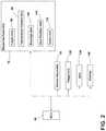
- FIG. 2is a schematic of a portion of an embodiment of a seat assembly according to teachings of the present disclosure.
- FIG. 3is a flow chart generally illustrating an embodiment of a method of operating seat assembly according to teachings of the present disclosure.
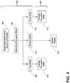
- FIG. 4is a flow chart generally illustrating an embodiment of a method of determining and changing the state of an occupant according to teachings of the present disclosure.
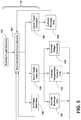
- FIG. 5is a flow chart generally illustrating an embodiment of a method of operating the fidget unit and portions of the response assembly according to teachings of the present disclosure.
- a seat assembly 20may include a seat 22 , an electronic control unit (ECU) 40 , a sensor assembly 50 , and/or a response assembly 70 .
- the seat assembly 20may be configured to sense and/or change a state (e.g., a physical state) of an occupant 36 in the seat 22 .
- the seat assembly 20may be substantially disposed in a vehicle 24 .
- the seat 22may include a seat base 26 and/or a seat back 28 .
- the seat 22may be connected to a track assembly 30 .
- the track assembly 30may be connected to a mounting surface 32 (e.g., a floor of a vehicle 24 ).
- the seat 22may be configured to move in an X-direction via the track assembly 30 .
- the ECU 40may be connected (electrically and/or mechanically) to the seat 22 and/or may be disposed in the seat 22 and/or a vehicle cabin 34 .
- the seat assembly 20may include a sensor assembly 50 and/or a response assembly 70 .
- the ECU 40may be configured to communicate with and/or control the sensor assembly 50 and/or the response assembly 70 .
- the ECU 40may be configured to receive information from the sensor assembly 50 and the ECU 40 may be configured to send information to the response assembly 70 and/or receive information from the response assembly 70 .
- a seat assembly 20may include a sensor assembly 50 .
- the sensor assembly 50may be configured to collect biometric information regarding an occupant 36 that may be seated in the seat 22 .
- a non-limiting example of a sensor assemblyis generally described in U.S. Pat. No. 10,034,631, which is hereby incorporated by reference as though fully set forth herein.
- a sensor assembly 50may be configured to sense (e.g., measure, monitor, detect, obtain, determine, etc.) characteristics, such as biometric data, of an occupant 36 and/or may transmit the information to the ECU 40 .
- the sensor assembly 50may include one or more sensors 52 that may include a biometric sensor and/or a piezoelectric sensor.
- the sensors 52may collect biometric information regarding the occupant 36 when the occupant 36 is in contact with and/or near the seat 22 .
- the sensors 52may be disposed in, disposed proximate, and/or connected to the seat base 26 and/or the seat back 28 of the seat 22 .
- the sensor assembly 50may be configured to sense vital information of an occupant 36 seated in the respective seat 22 .
- the sensor assembly 50may measure and/or collect data regarding the heart rate, the breathing rate, and/or the heart rate variability of an occupant 36 .
- the sensor assembly 50may be configured to transmit the vital information of the occupant 36 to the ECU 40 and the ECU 40 may determine a state of an occupant 36 according to (e.g., based on, utilizing, etc.), at least in part, the vital information.
- the ECU 40 and/or the sensor assembly 50may be configured to determine a state of an occupant 36 .
- the ECU 40may compare information from the sensors 52 to a first breathing rate threshold, a second breathing rate threshold, a first heart rate threshold, a second heart rate threshold, a first heart rate variability threshold, and/or a second heart rate variability threshold.
- the first thresholdsmay include a value less than the second thresholds.
- the first breathing rate thresholdmay be less than the second breathing rate threshold
- the first heart rate thresholdmay be less than the second heart rate threshold
- the first heart rate variability thresholdmay be less than the second heart rate variability threshold.
- the first statemay correspond to an occupant 36 that may be in a state of hypo-reactivity and/or may not be sufficiently alert to operate a vehicle 24 .
- the vital information of the occupant 36may not all be between the first thresholds and the second thresholds.
- the heart rate of the occupant 36may be below (e.g., less than) the first heart rate threshold; the breathing rate of the occupant 36 may be below (e.g., less than) the first breathing rate threshold; and/or the heart rate variability of the occupant 36 may be above (e.g., greater than) the second heart rate variability threshold.
- the second statemay correspond to an occupant 36 that may not be in a state of hypo-reactivity or hyper-reactivity.
- the occupant 36may be in a normal or healthy condition (e.g., the occupant 36 may be sufficiently alert and/or responsive to operate a vehicle 24 ).
- the sensor assembly 50may sense normal conditions for the vitals of an occupant 36 if the occupant 36 is in the second state.
- the heart rate of the occupant 36when the occupant 36 is in the second state, the heart rate of the occupant 36 may be between the first heart rate threshold and the second heart rate threshold; the breathing rate of the occupant 36 may be between the first breathing rate threshold and the second breathing rate threshold; and/or the heart rate variability of the occupant 36 may be between the first heart rate variability threshold and the second heart rate variability threshold.
- the third statemay correspond to an occupant 36 being in a state of hyper-reactivity, high stress, and/or agitation, which may not be ideal for operating a vehicle 24 .
- the vital information of the occupant 36may not all be between the first thresholds and the second thresholds.
- the heart rate of the occupant 36may be above (e.g., greater than) the second heart rate threshold; the breathing rate of the occupant 36 may be above (e.g., greater than) the second breathing rate threshold; and/or the heart rate variability of the occupant 36 may be below (e.g., less than) the first heart rate variability threshold.
- the seat assembly 20may include a response assembly 70 .
- the ECU 40may be configured to communicate with and/or control the response assembly 70 .
- the ECU 40may be configured to receive information from the sensor assembly 50 and/or activate the response assembly 70 according to the received information.
- the ECU 40may be configured to compare information from the sensor assembly 50 to the thresholds to determine how to activate the response assembly 70 to change the state of the occupant 36 from the current state to the second state (if the occupant 36 is not already in the second state).
- the response assembly 70may include one or more of a variety of units.
- the response assembly 70may include a haptic unit 80 , a temperature control unit 90 , a massage unit 100 , a seat position unit 110 , and/or an audio unit 120 , among others.
- a response assembly 70may include a haptic unit 80 .
- the ECU 40may be configured to control the haptic unit 80 .
- the haptic unit 80may be disposed in the seat base 26 and/or the seat back 28 .
- the haptic unit 80may be configured to send a vibration and/or an impulse to the occupant 36 through the seat base 26 and/or the seat back 28 .
- a haptic unit 80may, for example and without limitation, include one or more electric motors connected to unbalanced loads.
- the haptic unit 80may be configured to send one or more of a variety of different impulses.
- the haptic unit 80may transmit a quick impulse, a slow impulse, a strong impulse, and/or a weak impulse to the occupant 36 .
- a response assembly 70may include a temperature control unit 90 .
- the ECU 40may be configured to control the temperature control unit 90 .
- the temperature control unit 90may or may not be connected to an HVAC module of a vehicle 24 .
- the temperature control unit 90may be configured to change the temperature (e.g., an air temperature and/or a surface temperature) of an area proximate the seat 22 and/or the occupant 36 .
- the temperature control unit 90may be configured to control the direction of air flow and/or the speed of air flow to the occupant 36 .
- the temperature control unit 90may be connected to the seat base 26 and/or seat back 28 , such as to provide heated seat and/or ventilated seat functions.
- the temperature control unit 90may be configured to increase and/or decrease the air temperature of the vehicle cabin 34 , the temperature of the seat base 26 , and/or the temperature of the seat back 28 .
- a response assembly 70may include a massage unit 100 , and/or the ECU 40 may be configured to control the massage unit 100 .
- the massage unit 100may include one or more massagers 102 that may be configured to massage an occupant 36 .
- the seat base 26 and/or the seat back 28may include one or more massagers 102 .
- the massagers 102may be configured to inflate, deflate, and/or actuate.
- the massagers 102may be configured to operate at a high speed, low speed, high intensity, and/or low intensity.
- the massage unit 100may be configured to operate in a first mode and/or a second mode.
- At least one massager 102may be operated at a high speed and/or high intensity.
- at least one massager 102may be operated at a low speed and/or low intensity.
- the haptic unit 80 and the massage unit 100may, for example and without limitation, be integrated with each other and/or may be the same unit.
- a response assembly 70may include a seat position unit 110 .
- the ECU 40may be configured to control the seat position unit 110 .
- the seat position unit 110may be configured to move the seat 22 in the X-direction, Y-direction, and/or Z-direction, rotate the seat 22 , tilt the seat 22 , and/or move the seat 22 .
- the seat position unit 110may include one or more motors that may be connected to the seat base 26 , the seat back 28 , and/or the track assembly 30 .
- the seat position unit 110may change the angle of the seat base 26 and/or the seat back 28 .
- the seat position unit 110may increase and/or decrease the angle ⁇ between the seat base 26 and the seat back 28 .
- the seat position unit 110may change the position of the seat 22 between a relaxed position and an upright position.
- the relaxed positionmay include an angle ⁇ between the seat base 26 and the seat back 28 that may be greater than the angle ⁇ of the seat base 26 and the seat back 28 when in the upright position.
- the response assembly 70may include an audio unit 120 .
- the ECU 40may be configured to control the audio unit 120 .
- the audio unit 120may be connected to a sound system of a vehicle 24 .
- the audio unit 120may include one or more speakers 122 that may be disposed in the vehicle cabin 34 .
- one or more speakers 122may be disposed on the seat base 26 and/or the seat back 28 .
- One or more speakers 122may be disposed on/in the seat back 28 , such as proximate a head of an occupant 36 (e.g., the speakers 122 may be disposed near the headrest 38 ).
- the audio unit 120may be configured to control the volume and/or the content of sound played within the vehicle cabin 34 .
- the audio unit 120may be configured to play soothing music and/or vigorous music.
- the audio unit 120may be configured to increase and/or decrease the volume of the sound in the vehicle cabin 34 .
- the audio unit 120may be configured to broadcast an audio alert to an occupant 36 .
- the alertmay include an inquiry to the occupant 36 about whether the occupant 36 desires to take a break from operating the vehicle 24 . If the occupant 36 responds in the positive, the ECU 40 may activate a global positioning system (GPS) unit 138 to determine the closest location to safely stop the vehicle 24 , such as rest area or point of interest (e.g., restaurant, coffee shop, gas station, etc.). If the occupant 36 responds in the negative, the ECU 40 may inquire again after an amount of time.
- GPSglobal positioning system
- the ECU 40may be configured to activate at least one of the haptic unit 80 , the temperature control unit 90 , the massage unit 100 , the seat position unit 110 , and/or the audio unit 120 in accordance with the determined state of the occupant 36 .
- the ECU 40may be configured to activate units of the response assembly 70 in different manners based on whether the occupant 36 is in the first state, the second state, and/or the third state.
- the ECU 40may activate the response assembly 70 to change the state of the occupant 36 from the first state to the second state.
- the ECU 40may be configured to activate the response assembly 70 to increase the heart rate of the occupant 36 , increase the breathing rate of the occupant 36 , and/or decrease the heart rate variability of the occupant 36 .
- the ECU 40may be configured to activate the haptic unit 80 , the temperature control unit 90 , the massage unit 100 , the seat position unit 110 , and/or the audio unit 120 .
- the ECU 40may measure and/or store the information of the occupant 36 regarding the heart rate, the breathing rate, and/or the heart rate variability prior to activating the response assembly 70 .
- the ECU 40may be configured to increase the heart rate of the occupant 36 until the heart rate is between a first heart rate threshold and a second heart rate threshold (e.g., between a lower nominal value and an upper nominal value).
- the ECU 40may be configured to increase the breathing rate of the occupant 36 until the breathing rate is between the first breathing rate threshold and the second breathing rate threshold.
- the ECU 40may be configured to decrease the heart rate variability of the occupant 36 until the heart rate variability is between the first heart rate variability threshold and the second heart rate variability threshold.
- the ECU 40may measure and/or store the information of the occupant 36 regarding the heart rate, the breathing rate, and/or the heart rate variability after activating the response assembly 70 .
- activating the response assembly 70 to change the state of the occupant 36 from the first state to the second statemay include the ECU 40 activating the haptic unit 80 to transmit a strong/quick impulse to the occupant 36 via the seat base 26 and/or the seat back 28 . Additionally or alternatively, the ECU 40 may activate the temperature control unit 90 to change the state of the occupant 36 from the first state to the second state.
- the ECU 40may decrease the temperature inside the vehicle cabin 34 , direct air flow in a direction towards the occupant 36 , increase the speed of air flow, and/or activate the seat base 26 and/or seat back 28 ventilation functions, one or more of which may generally lead to an increase in heart rate, an increase in breathing rate, and/or a decrease in heart rate variability.
- the ECU 40may activate the massage unit 100 to change the state of the occupant 36 from the first state to the second state.
- the ECU 40via the massage unit 100
- the ECU 40may activate the seat position unit 110 to change the state of the occupant 36 from the first state to the second state. For example and without limitation, the ECU 40 (via the seat position unit 110 ) may decrease the angle ⁇ between the seat base 26 and the seat back 28 , which may result in the seat 22 being disposed in a more upright position, which may tend to make the occupant 36 more alert.
- the ECU 40may activate the audio unit 120 to change the state of the occupant 36 from the first state to the second state. For example and without limitation, the ECU 40 (via the audio unit 120 ) may increase the volume of sound (e.g., music) inside the vehicle cabin 34 and/or the audio unit 120 may play vigorous sounds/music. Additionally or alternatively, the ECU 40 may activate an audio alert to indicate to the occupant 36 that a rest area (e.g., rest stop, restaurant, gas station, etc.) is nearby.
- a rest areae.g., rest stop, restaurant, gas station, etc.
- the ECU 40may activate the response assembly 70 to change the state of the occupant 36 from the third state to the second state.
- the ECU 40may be configured to activate the response assembly 70 to decrease the heart rate of the occupant 36 , decrease the breathing rate of the occupant 36 , and/or increase the heart rate variability of the occupant 36 .
- the ECU 40may, for example, be configured to activate the haptic unit 80 , the massage unit 100 , the seat position unit 110 , and/or the audio unit 120 .
- the ECU 40may measure and/or store the information of the occupant 36 regarding the heart rate, the breathing rate, and/or the heart rate variability prior to activating the response assembly 70 .
- the ECU 40may be configured to decrease the heart rate of the occupant 36 until the heart rate is between the first heart rate threshold and the second heart rate threshold.
- the ECU 40may be configured to decrease the breathing rate of the occupant 36 until the breathing rate is between the first breathing rate threshold and the second breathing rate threshold.
- the ECU 40may be configured to increase the heart rate variability of the occupant 36 until the heart rate variability is between the first heart rate variability threshold and the second heart rate variability threshold.
- the ECU 40may measure and/or store the information of the occupant 36 regarding the heart rate, the breathing rate, and/or the heart rate variability after activating the response assembly 70 (e.g., may store an effectiveness of various activations of the response assembly 70 for the particular occupant 36 ).
- changing the state of the occupant 36 from the third state to the second statemay, for example, include the ECU 40 activating the haptic unit 80 to transmit a weak/slow impulse to the occupant 36 via the seat base 26 and/or the seat back 28 .
- the ECU 40may activate the massage unit 100 to change the state of the occupant 36 from the third state to the second state.
- the ECU 40via the massage unit 100 ) may activate one or more massagers 102 in the seat base 26 and/or the seat back 28 in a second mode (e.g., low speed/low intensity).
- the ECU 40may activate the seat position unit 110 to change the state of the occupant 36 from the third state to the second state.
- the ECU 40(via the seat position unit 110 ) may increase the angle ⁇ between the seat base 26 and the seat back 28 , such as to provide a more reclined or relaxed seating configuration.
- the ECU 40may activate the audio unit 120 to change the state of the occupant 36 from the third state to the second state.
- the ECU 40(via the audio unit 120 ) may decrease the volume of sound (e.g., music) inside the vehicle cabin 34 and/or the audio unit 120 may play soothing sounds/music.
- the ECU 40may alert and/or inform the occupant 36 that the occupant 36 may need a break from operating the vehicle 24 (if seated in the driver seat) and/or may activate an audio alert to indicate to the occupant 36 that a rest area (e.g., rest stop, restaurant, gas station, etc.) is nearby.
- a rest areae.g., rest stop, restaurant, gas station, etc.
- the ECU 40may not activate the response assembly 70 to change the heart rate, the breathing rate, and/or the heart rate variability of the occupant 36 .
- the sensor assembly 50may continue to sense the heart rate, the breathing rate, and/or the heart variability in order to detect if the state of the occupant 36 changes from the second state to the first state and/or the third state.
- the seat assembly 20may include a fidget unit 130 , and/or the fidget unit 130 may be connected to the ECU 40 .
- the ECU 40may be configured to control the fidget unit 130 .
- the fidget unit 130may be configured to determine whether an occupant 36 is fidgeting, which may suggest that the occupant 36 is not comfortable.
- the fidget unit 130may be activated, for example, when the occupant 36 in in the second state.
- the fidget unit 130may include one or more actuators (e.g., bladders) 132 that may be configured to inflate and/or deflate.
- the ECU 40may be configured to control the inflation and/or deflation of the bladders 132 .
- the bladders 132may be at least partially disposed in the seat base 26 and/or the seat back 28 .
- the bladders 132may include and/or be connected to one or more sensors 134 that may be configured to sense changes in pressure in the bladders 132 , which may correspond to movement (e.g., fidgeting) of the occupant 36 .
- the ECU 40may be configured to inflate and/or deflate the bladders 132 to reduce the severity and/or amount of fidgeting (e.g., to make the occupant 36 more comfortable).
- the fidget unit 130may be connected to and/or include one or more units of the response assembly 70 , such as, for example and without limitation, the massage unit 100 .
- the ECU 40may be configured to detect an occupant 36 , retrieve a profile of an occupant 36 , and/or store/modify a profile of an occupant 36 .
- the ECU 40may be connected to one or more biometric sensors 52 of the sensor assembly 50 that may be configured to detect/identify a specific occupant 36 that may be seated in a seat 22 . If the ECU 40 is unable to identify an occupant 36 , the ECU 40 may create a new profile for the occupant 36 .
- the profile of the occupant 36may include information including the effectiveness of actions (of units) of the response assembly 70 .
- the ECU 40may be configured to measure the effectiveness of a specific unit of the response assembly 70 on the heart rate, the breathing rate, and/or the heart rate variability of the occupant 36 .
- the ECU 40may obtain the heart rate, the breathing rate, and/or the heart rate variability of the occupant 36 prior to activating a unit of the response assembly 70 ; and/or the ECU 40 may obtain the heart rate, the breathing rate, and/or the heart rate variability of the occupant 36 after activating a unit of the response assembly 70 .
- the ECU 40may record the amount the response assembly 70 affected the heart rate, the breathing rate, and/or the heart rate variability of the occupant 36 .
- the stored profile of an occupant 36may include information regarding the more effective units of the response assembly 70 , and/or the ECU 40 may prioritize adjusting the more effective units when changing the state of the occupant 36 from the first state or third state to the second state.
- the ECU 40may store one or more occupant profiles, and/or each profile may prioritize different units when changing the heart rate, the breathing rate, and/or the heart rate variability of the occupant 36 .
- the ECU 40may be configured to analyze an occupant profile, and/or the ECU 40 may be configured to determine a response (e.g., an activation of the response assembly 70 ) that may be effective in changing the state of the occupant 36 from the third state to the second state based on information relating to previously changing the state of the occupant 36 from the first state to the second state.
- the ECU 40may analyze the effective units of the response assembly 70 in increasing the heart rate, increasing the breathing rate, and/or decreasing the heart rate variability of the occupant 36 ; and/or the ECU 40 may activate the units in an opposite/inverse manner to decrease the heart rate, decrease the breathing rate, and/or increase the heart rate variability of the occupant 36 .
- the ECU 40may activate the massage unit 100 to massage the occupant 36 in the second mode (e.g., low intensity/low frequency) to decrease the heart rate and/or the breathing rate of the occupant 36 .
- the ECU 40may monitor the effectiveness of the response on the heart rate, the breathing rate, and/or the heart rate variability of the occupant 36 , and/or the ECU 40 may store the response information with the occupant profile.
- a method 150 of operating a seat assembly 20may include providing a seat 22 , an ECU 40 , a sensor assembly 50 , and/or a response assembly 70 .
- the method 150may include initializing the sensor assembly 50 (step 152 ).
- Initializing the sensor assembly 50may include determining whether an occupant 36 is seated in the seat 22 , providing power to the sensor assembly 50 , determining whether the ECU 40 includes an associated occupant profile, and/or creating a profile for an unidentified occupant 36 . If a profile of an occupant 36 is not identified, the ECU 40 may create a profile including and/or associated with biometric data of the occupant 36 that may be obtained via one or more biometric sensors.
- the method 150may include calibrating the sensor assembly 50 (step 154 ). Calibrating the sensor assembly 50 may include a delay (e.g., about 10-15 seconds or more or less) to measure biometric information of the occupant 36 over a period of time.
- the ECU 40may display a message to a display 140 that may indicate to an occupant 36 to sit still (e.g., to receive accurate measurements/data).
- the ECU 40may activate the sensors 52 of the sensor assembly 50 to test the functionality. If the sensors 52 successfully gather information of the occupant 36 , sensor calibration (step 154 ) may be completed. If the sensors 52 do not gather information of the occupant 36 (e.g., the data is corrupt, a sensor malfunctions, etc.), the ECU 40 may restart the sensor calibration (step 154 ).
- a method 150 of operating a seat assembly 20may include comparing information from the sensor assembly 50 to one or more thresholds (step 156 ). Comparing the sensor assembly data (step 156 ) may include comparing the sensed heart rate, the breathing rate, and/or the heart variability to an average heart rate, an average breathing rate, and/or an average heart rate variability associated with an occupant profile. If the sensed values of the heart rate, the breathing rate, and/or the heart rate variability are not substantially similar to the stored averages (e.g., within threshold values or ranges), the ECU 40 may transmit a notification to the display 140 , such as a suggestion that the occupant 36 should contact a medical professional.
- a method 150 of operating a seat assembly 20may include determining the state of the occupant 36 (step 158 ).
- the ECU 40may receive information from the sensor assembly 50 .
- the ECU 40may activate the sensor assembly 50 to sense the heart rate, the breathing rate, and/or the heart rate variability of the occupant 36 .
- the ECU 40may compare the heart rate, the breathing rate, and/or the heart rate variability of the occupant 36 to the respective first thresholds and the second thresholds of the heart rate, the breathing rate, and/or the heart rate variability.
- the method 150 of operating the seat assembly 20may include verifying a false alarm (step 160 ).
- the ECU 40may transmit an alert to the display 140 inquiring whether the occupant 36 would like to stop the vehicle 24 to re-measure via the sensor assembly 50 . If the occupant 36 responds in the affirmative, the ECU 40 may wait until the vehicle 24 is in park/stopped to restart one or more steps of the method 150 , such as activating the sensor assembly 50 (step 152 ) and/or remeasuring the heart rate, the breathing rate, and/or the heart rate variability (step 158 ).
- the ECU 40may be configured to transmit a warning to a vehicle assistance program (e.g., that may be connected to a wireless network, such as, for example and without limitation, a cellular connection to OnStar). If the ECU 40 receives correct data from the sensor assembly 50 , the ECU 40 may adjust the state of the occupant 36 (step 162 ).
- a vehicle assistance programe.g., that may be connected to a wireless network, such as, for example and without limitation, a cellular connection to OnStar.
- a method 150 of operating the seat assembly 20may include determining the state of the occupant 36 (step 158 ) and/or changing the state of the occupant 36 (step 162 ).
- the ECU 40may read/receive information from the sensor assembly (step 164 ), and/or determine the state of the occupant 36 (step 166 ). If the occupant 36 is determined by the ECU 40 to be in the first state (step 168 ), the ECU 40 may be configured to activate the haptic unit 80 , the temperature control unit 90 , the massage unit 100 , the seat position unit 110 , and/or the audio unit 120 to change the state of the occupant 36 from the first state to the second state (step 170 ).
- the ECU 40may be configured to activate the haptic unit 80 , the massage unit 100 , the seat position unit 110 , and/or the audio unit 120 to change the state of the occupant 36 from the third state to the second state (step 174 ).
- a method 150 of operating a seat assembly 20may include detecting fidgets (e.g., detecting movement of the occupant 36 in the seat 22 ) (step 178 ). If the ECU 40 determines that the occupant 36 is in the second state (step 176 ), the ECU 40 may detect fidgets of the occupant 36 (step 178 ). If the ECU 40 determines that the occupant 36 is in the first state or the third state, the ECU 40 may not activate the fidget unit 130 and/or may not detect fidgets. The ECU 40 may prioritize changing the state of the occupant 36 from the first state and/or the third state to the second state over reducing the number and/or severity of fidgets.
- fidgetse.g., detecting movement of the occupant 36 in the seat 22
- detecting fidgetsmay include activating the fidget sensors 134 (step 182 ), the ECU 40 receiving information from the fidget sensors 134 (step 184 ), and/or activating one or more units of the response assembly 70 (steps 188 , 192 , 194 , 196 ) and/or the actuators 132 of the fidget unit 130 .
- Receiving information from the fidget sensors 134 (step 184 )may include measuring the number of fidgets of the occupant 36 (e.g., the number of movements of the occupant 36 in the seat 22 via the fidget sensors 134 ).
- the ECU 40may analyze the fidget information to detect a large fidget (step 186 ) or detect a small fidget (step 190 ). If the ECU 40 detects a large fidget/significant fidgeting (step 186 ), the ECU 40 may activate the massage unit 100 (step 188 ). Activating the massage unit 100 may, for example, include massaging and/or stretching the spine of the occupant 36 via the massagers 102 of the massage unit 100 (e.g., the massagers 102 proximate the lumbar of the occupant 36 may be activated by the ECU 40 ).
- the ECU 40may activate massagers 102 in the seat base 26 and/or the seat back 28 that may be proximate the location of the detected fidgets (e.g., as sensed via the fidget sensors 134 ). If the ECU 40 detects a small fidget/minor fidgeting (step 190 ), the ECU 40 may activate the massage unit 100 (step 192 ), the temperature control unit 90 (step 194 ), and/or activate the actuators 132 of the fidget unit 130 (e.g., inflate/deflate bladders) (step 196 ).
- the actuators 132 of the fidget unit 130e.g., inflate/deflate bladders
- the ECU 40may activate massagers 102 proximate the lumbar of the occupant 36 , the ECU 40 may reduce the temperature of the vehicle cabin 34 proximate the occupant 36 , the ECU 40 may direct air flow in a direction towards the occupant 36 , the ECU 40 may activate the ventilation function of the seat 22 , and/or the ECU 40 may inflate/deflate bladders 132 proximate the sensed fidgets. If the number of measured fidgets is less than the second fidget threshold, the ECU 40 may detect insignificant or no fidgeting (step 198 ).
- the ECU 40may continue to receive information from the fidget sensors 134 until the number of fidgets measured is greater than the second fidget threshold (e.g., the second fidget threshold may be less than the first fidget threshold).
- the ECU 40may be configured to operate the fidget unit 130 while determining/changing the state of an occupant 36 , such as regardless of what state the occupant 36 is in.
- the ECU 40may activate the response assembly 70 and the fidget unit 130 simultaneously to change the state of the occupant 36 and to reduce fidgeting.
- the ECU 40may monitor patterns of the types of fidgeting of an occupant 36 when the occupant 36 is in each state, store such patterns in an occupant profile, and/or use such patterns in determining the state of the occupant 36 .
- the actions for changing the state of the occupant 36may supersede the actions for reducing fidgeting (e.g., changing the state of the occupant 36 may improve the safety of the occupant 36 and reducing fidgeting may improve the comfort of the occupant 36 ).
- an ECU 40may be configured to determine if an occupant 36 is a driver/operator or a passenger. If the occupant 36 is a passenger, the ECU 40 may activate the fidget unit 130 even if the ECU 40 determines that the occupant 36 is in the first state or the second state. For example and without limitation, a passenger may be in the first state if the passenger is attempting to sleep and the ECU 40 may activate the fidget unit 130 to make the passenger more comfortable (to facilitate sleep). If the occupant 36 is a passenger, the ECU 40 may not change the state of the occupant 36 from the first state to the second state unless requested by the occupant 36 .
- an ECU 40may be configured to monitor an occupant 36 over a relatively long period of time (e.g., days, weeks, months, years, etc.) and/or across a plurality of instances of the occupant 36 sitting in a seat. For example and without limitation, the ECU 40 may determine, such as via the sensor assembly 50 , that the heart rate of an occupant 36 is significantly higher than previously sensed (e.g., a week ago). The ECU 40 may be configured to alert an occupant 36 of changes and/or suggest that the occupant 36 seek medical assistance.
- a relatively long period of timee.g., days, weeks, months, years, etc.
- the ECU 40may determine, such as via the sensor assembly 50 , that the heart rate of an occupant 36 is significantly higher than previously sensed (e.g., a week ago).
- the ECU 40may be configured to alert an occupant 36 of changes and/or suggest that the occupant 36 seek medical assistance.
- an ECUmay include an electronic controller and/or include an electronic processor, such as a programmable microprocessor and/or microcontroller.
- an ECUmay include, for example, an application specific integrated circuit (ASIC).
- An ECUmay include a central processing unit (CPU), a memory unit (e.g., a non-transitory computer-readable storage medium), and/or an input/output (I/O) interface.
- An ECUmay be configured to perform various functions, including those described in greater detail herein, with appropriate programming instructions and/or code embodied in software, hardware, and/or other medium.
- an ECUmay include a plurality of controllers.
- an ECUmay be connected to a display (e.g., display 140 ), such as a touchscreen display.
- references to a single elementare not necessarily so limited and may include one or more of such element.
- Any directional referencese.g., plus, minus, upper, lower, upward, downward, left, right, leftward, rightward, top, bottom, above, below, vertical, horizontal, clockwise, and counterclockwise
- Any directional referencesare only used for identification purposes to aid the reader's understanding of the present disclosure, and do not create limitations, particularly as to the position, orientation, or use of embodiments.
- joinder referencesare to be construed broadly and may include intermediate members between a connection of elements and relative movement between elements. As such, joinder references do not necessarily imply that two elements are directly connected/coupled and in fixed relation to each other.
- the use of “e.g.” in the specificationis to be construed broadly and is used to provide non-limiting examples of embodiments of the disclosure, and the disclosure is not limited to such examples.
- Uses of “and” and “or”are to be construed broadly (e.g., to be treated as “and/or”). For example and without limitation, uses of “and” do not necessarily require all elements or features listed, and uses of “or” are intended to be inclusive unless such a construction would be illogical.
Landscapes
- Health & Medical Sciences (AREA)
- Engineering & Computer Science (AREA)
- Life Sciences & Earth Sciences (AREA)
- General Health & Medical Sciences (AREA)
- Heart & Thoracic Surgery (AREA)
- Animal Behavior & Ethology (AREA)
- Public Health (AREA)
- Veterinary Medicine (AREA)
- Physics & Mathematics (AREA)
- Biomedical Technology (AREA)
- Mechanical Engineering (AREA)
- Transportation (AREA)
- Aviation & Aerospace Engineering (AREA)
- Surgery (AREA)
- Molecular Biology (AREA)
- Biophysics (AREA)
- Pathology (AREA)
- Medical Informatics (AREA)
- Cardiology (AREA)
- Physiology (AREA)
- Psychology (AREA)
- Developmental Disabilities (AREA)
- Anesthesiology (AREA)
- Pulmonology (AREA)
- Educational Technology (AREA)
- Social Psychology (AREA)
- Child & Adolescent Psychology (AREA)
- Hospice & Palliative Care (AREA)
- Pain & Pain Management (AREA)
- Acoustics & Sound (AREA)
- Hematology (AREA)
- Psychiatry (AREA)
- Epidemiology (AREA)
- Physical Education & Sports Medicine (AREA)
- Rehabilitation Therapy (AREA)
- Seats For Vehicles (AREA)
- Measuring Pulse, Heart Rate, Blood Pressure Or Blood Flow (AREA)
Abstract
Description
Claims (20)
Priority Applications (2)
| Application Number | Priority Date | Filing Date | Title |
|---|---|---|---|
| US16/523,102US11052223B2 (en) | 2017-12-21 | 2019-07-26 | Seat assembly and method |
| DE102020209445.4ADE102020209445A1 (en) | 2019-07-26 | 2020-07-27 | Seat layout and procedure |
Applications Claiming Priority (2)
| Application Number | Priority Date | Filing Date | Title |
|---|---|---|---|
| US15/851,003US10569668B2 (en) | 2017-12-21 | 2017-12-21 | Occupant and fidget detection of a seat assembly |
| US16/523,102US11052223B2 (en) | 2017-12-21 | 2019-07-26 | Seat assembly and method |
Related Parent Applications (1)
| Application Number | Title | Priority Date | Filing Date |
|---|---|---|---|
| US15/851,003Continuation-In-PartUS10569668B2 (en) | 2017-12-21 | 2017-12-21 | Occupant and fidget detection of a seat assembly |
Publications (2)
| Publication Number | Publication Date |
|---|---|
| US20190344043A1 US20190344043A1 (en) | 2019-11-14 |
| US11052223B2true US11052223B2 (en) | 2021-07-06 |
Family
ID=68465032
Family Applications (1)
| Application Number | Title | Priority Date | Filing Date |
|---|---|---|---|
| US16/523,102Active2038-01-23US11052223B2 (en) | 2017-12-21 | 2019-07-26 | Seat assembly and method |
Country Status (1)
| Country | Link |
|---|---|
| US (1) | US11052223B2 (en) |
Families Citing this family (20)
| Publication number | Priority date | Publication date | Assignee | Title |
|---|---|---|---|---|
| US10518685B2 (en)* | 2017-03-08 | 2019-12-31 | Ts Tech Co., Ltd. | Conveyance seat |
| US11186338B2 (en)* | 2017-08-24 | 2021-11-30 | Polaris Industries Inc. | Remote control system for comfort-management device(s) |
| US11760434B2 (en) | 2019-01-07 | 2023-09-19 | Polaris Industries Inc. | Recreational vehicles with heated components |
| US11858392B2 (en)* | 2019-03-01 | 2024-01-02 | Ts Tech Co., Ltd. | Vehicle seat and vehicle provided with vehicle seat |
| JP7385103B2 (en)* | 2019-07-02 | 2023-11-22 | テイ・エス テック株式会社 | vehicle seat |
| US11279270B2 (en)* | 2019-10-25 | 2022-03-22 | Zoox, Inc. | Occupant protection system and method including seatback |
| US11059490B1 (en) | 2020-03-17 | 2021-07-13 | Lear Corporation | Seat system |
| US11584278B2 (en)* | 2020-03-30 | 2023-02-21 | Faurecia Automotive Seating, Llc | Vehicle seat with a thermal massage system |
| US11590873B2 (en)* | 2020-05-13 | 2023-02-28 | Lear Corporation | Seat assembly |
| US11173818B1 (en) | 2020-05-13 | 2021-11-16 | Lear Corporation | Seat assembly |
| US11634055B2 (en)* | 2020-05-13 | 2023-04-25 | Lear Corporation | Seat assembly |
| US11292371B2 (en) | 2020-05-13 | 2022-04-05 | Lear Corporation | Seat assembly |
| CN115699800B (en)* | 2020-07-14 | 2025-07-11 | 阿尔卑斯阿尔派株式会社 | Vehicle system and vibration generating device |
| US20220054351A1 (en)* | 2020-08-21 | 2022-02-24 | Kohler Co. | Bath massage chair and pillow |
| US11679706B2 (en)* | 2020-12-02 | 2023-06-20 | Lear Corporation | Seat assembly |
| US20220257461A1 (en)* | 2021-02-12 | 2022-08-18 | Opus Immersive, Inc. | Vibroacoustic Therapy Bed with Stowable Form Factor |
| US11685329B2 (en) | 2021-03-30 | 2023-06-27 | Zoox, Inc. | Occupant protection system and method including seatback |
| FR3121883B1 (en)* | 2021-04-19 | 2024-08-30 | Faurecia Sieges Dautomobile | Vehicle seat |
| US11623597B1 (en) | 2022-01-31 | 2023-04-11 | Zoox, Inc. | Multipurpose seatback bladder system for crash safety and lumbar support |
| US12151823B2 (en)* | 2022-08-31 | 2024-11-26 | Rockwell Collins, Inc. | High comfort endurance haptic cushion |
Citations (157)
| Publication number | Priority date | Publication date | Assignee | Title |
|---|---|---|---|---|
| US5769490A (en) | 1993-12-24 | 1998-06-23 | Henderson's Industries Pty. Ltd. | Adjustable lumbar support |
| US6056360A (en) | 1996-06-17 | 2000-05-02 | American Components, Inc. | Adjustable lumbar seat support |
| US6088643A (en) | 1994-06-24 | 2000-07-11 | Mccord Winn Textron Inc. | Interactive, individually controlled, multiple bladder seating comfort adjustment system |
| US6088642A (en) | 1998-07-29 | 2000-07-11 | Mccord Winn Textron Inc. | Interactive, individually controlled, multiple bladder seating comfort adjustment system and method |
| EP1077154A2 (en) | 1999-08-14 | 2001-02-21 | Volkswagen Aktiengesellschaft | Vehicle seat |
| JP2001269380A (en) | 2000-03-27 | 2001-10-02 | Sanyo Electric Co Ltd | Massaging machine |
| DE10027686A1 (en) | 2000-05-26 | 2002-01-17 | Volkswagen Ag | Vehicle seat which is convertible into a bunk |
| US6345839B1 (en) | 1997-01-13 | 2002-02-12 | Furukawa Electronics Co., Ltd. | Seat fitted with seating sensor, seating detector and air bag device |
| US6353207B1 (en) | 2000-08-17 | 2002-03-05 | Ctex Seat Comfort Ltd. | Expandable chamber having combined occupant support and heating |
| DE10063478A1 (en) | 2000-12-20 | 2002-07-04 | Alfmeier Praez Ag | Seat for use in vehicle has device enabling amplitude of forward stroke and/or frequency of massage stroke to be changed with help of control element |
| US6506153B1 (en) | 1998-09-02 | 2003-01-14 | Med-Dev Limited | Method and apparatus for subject monitoring |
| US20030075959A1 (en) | 2001-10-22 | 2003-04-24 | Ryan Xue | Apparatus and method for cyclic adjustment of a supporting element in a seat |
| US6682494B1 (en) | 1999-08-17 | 2004-01-27 | Inseat Solutions, Llc | Massaging system having isolated vibrators |
| US20040119599A1 (en) | 2002-12-20 | 2004-06-24 | Robin Stevenson | Seat belt status monitoring system |
| JP2005137896A (en) | 2003-10-16 | 2005-06-02 | Sanyo Electric Co Ltd | Relaxation system, relaxation method and relaxation program |
| DE102004010626A1 (en) | 2004-03-02 | 2005-06-16 | Alfmeier Präzision AG Baugruppen und Systemlösungen | Inflatable cushion for car seat whose contours can be adjusted comprises upper and lower impermeable sheets which are separated by spacer sheet which is fastened to their inner sides at several points |
| US6908152B2 (en) | 2001-12-14 | 2005-06-21 | L & P Property Management Company | Push lumbar support with flexible pressure surface |
| JP2005237456A (en) | 2004-02-24 | 2005-09-08 | Nissan Motor Co Ltd | Driver emotion induction device |
| DE102004013674A1 (en) | 2004-03-15 | 2005-10-06 | Volkswagen Ag | Seat for a motor vehicle, an aircraft or the like comprises at least within the back rest area an elastically compliant foam cushioning formed by covered pockets which contain open-cell, self-inflating foam |
| JP2006014756A (en) | 2004-06-30 | 2006-01-19 | Delta Tooling Co Ltd | Biological signal detection device, seat and seat belt |
| US7011369B2 (en) | 2001-07-11 | 2006-03-14 | Alfmeier Corporation | Integrated adjustable lumbar support and trim attachment system |
| US7083233B2 (en) | 2002-05-08 | 2006-08-01 | Alfmeier Corporation | Adjustable floating plate lumber support |
| US7083232B2 (en) | 2002-11-01 | 2006-08-01 | L&P Property Management Company | Massage apparatus and method for lumbar support |
| JP3857869B2 (en) | 2000-08-23 | 2006-12-13 | 東芝テック株式会社 | Massage equipment |
| US7152920B2 (en) | 2003-10-21 | 2006-12-26 | Ts Tech Co., Ltd. | Vehicle seat with system for facilitating relieving of fatigue of person sitting on the seat |
| CN2855822Y (en) | 2005-12-12 | 2007-01-10 | 朱志强 | Electric heating magnet therapy seat back cushion for automobile |
| EP1749477A1 (en) | 2004-05-24 | 2007-02-07 | Pioneer Corporation | Bioinformation sensor |
| US7219923B2 (en) | 2003-05-21 | 2007-05-22 | Delta Tooling Co., Ltd. | Device for determining kind of load on seat, seat, and bio-signal detector |
| US20070118054A1 (en) | 2005-11-01 | 2007-05-24 | Earlysense Ltd. | Methods and systems for monitoring patients for clinical episodes |
| US7267652B2 (en) | 2003-04-10 | 2007-09-11 | Vivometrics, Inc. | Systems and methods for respiratory event detection |
| US7314451B2 (en) | 2005-04-25 | 2008-01-01 | Earlysense Ltd. | Techniques for prediction and monitoring of clinical episodes |
| DE102006029871A1 (en) | 2006-06-28 | 2008-01-03 | Audi Ag | Vehicle seat, has backrest with side walls and changing device for changing curvature of rest sections that are arranged between walls, where one side wall is adjustable in direction of curvature and is coupled with curvature adjustments |
| EP1932715A1 (en) | 2006-12-16 | 2008-06-18 | Volkswagen Aktiengesellschaft | Vehicle seat with pneumatic lordosis |
| US7417536B2 (en) | 2003-03-13 | 2008-08-26 | Sridhar Lakshmanan | Living being presence detection system |
| US20080255731A1 (en) | 2007-04-12 | 2008-10-16 | Takata Corporation | Occupant detection apparatus |
| US20080267460A1 (en) | 2007-04-24 | 2008-10-30 | Takata Corporation | Occupant information detection system |
| US20090008970A1 (en) | 2004-12-16 | 2009-01-08 | Daimlerchrysler Ag | Backrest For A Motor Vehicle Seat With An Air Supply Device |
| DE102008029339A1 (en) | 2008-05-27 | 2009-01-22 | Daimler Ag | Motor vehicle i.e. passenger car, seat, has adjustment elements designed as auxiliary airbags, which are brought into protective configuration before or during collision in non-reversible manner |
| US20090030578A1 (en) | 2007-07-27 | 2009-01-29 | Peugeot Citroen Automobiles Sa | Method and device for detecting and classifying the position of an occupant of a vehicle seat |
| JP2009172145A (en) | 2008-01-24 | 2009-08-06 | Toyota Motor Corp | Sheet structure |
| DE102009008421A1 (en) | 2009-02-11 | 2009-10-15 | Daimler Ag | Vehicle seat for vehicle, has cushion of seat cushion or backrest, and massage unit with multiple pressurized elements, which are integrated and separately controlled for influencing seat contour in cushion |
| EP2149475A1 (en) | 2008-08-01 | 2010-02-03 | Alfmeier Präzision Ag Baugruppen und Systemlösungen | Seat with reforming device for adjusting the seat contour |
| DE102009035566A1 (en) | 2009-07-31 | 2010-02-18 | Daimler Ag | Vehicle seat has multiple massage elements, by which seat occupant is loaded on seat in area wise manner with pressure |
| US20100087748A1 (en) | 2008-10-07 | 2010-04-08 | Andreas Tobola | Device and method for sensing respiration of a living being |
| US7731279B2 (en) | 2004-04-28 | 2010-06-08 | Massachusetts Institute Of Technology | Rapid cooling and heating of car seats with massaging effects |
| DE102009031331A1 (en) | 2009-02-11 | 2010-08-12 | Daimler Ag | Vehicle seat for Mercedes-Benz S-class, has pad of seat cushion, where pressurizing elements are integrated in pad for influencing seat contour, and control unit is provided for controlling massage device and seat heating |
| US7808395B2 (en) | 2007-11-09 | 2010-10-05 | Emfit Oy | Occupancy detecting method and system |
| US7862119B2 (en) | 2005-04-08 | 2011-01-04 | Alfmeier Prazision Ag Baugruppen Und Systemlosungen | Vehicle seat with lordosis support |
| US7866755B2 (en) | 2007-09-13 | 2011-01-11 | Nhk Spring Co., Ltd. | Ottoman for vehicle seats |
| DE102009033041A1 (en) | 2009-07-03 | 2011-01-13 | Audi Ag | Vehicle seat has massage device, which holds multiple supporting components at laminar and has unbalance motor which is controlled by control device |
| US20110015468A1 (en)* | 2008-03-14 | 2011-01-20 | Koninklijke Philips Electronics N.V. | Method and system for maintaining a state in a subject |
| DE102010021332A1 (en) | 2010-05-22 | 2011-01-20 | Daimler Ag | Air conditioning system for interior part of motor vehicle, has control unit for controlling system and another system together such that passenger of motor vehicle is influenced with supply of air from one of systems |
| US7900736B2 (en) | 1995-06-07 | 2011-03-08 | Automotive Technologies International, Inc. | Vehicular seats with fluid-containing weight sensing system |
| US7967381B2 (en) | 2006-02-13 | 2011-06-28 | Ts Tech Co., Ltd. | Automobile seat with fatigue reduction function |
| US7967379B2 (en) | 2008-12-29 | 2011-06-28 | L&P Property Management Company | Seat with independently adjustable user support assemblies |
| DE102011012431A1 (en) | 2011-02-25 | 2011-11-10 | Daimler Ag | Adjustment device for seat system of vehicle, has one or more hollow bodies for changing seat contour of seat system, where bridge element is provided for overarching two hollow bodies |
| DE102010049152A1 (en) | 2010-05-21 | 2011-11-24 | Johnson Controls Gmbh | Vehicle seat with intelligent actuators |
| DE102011017238A1 (en) | 2011-04-15 | 2011-12-08 | Daimler Ag | Seating system for vehicle, has bridge element, which overstretches two hollow bodies, where bridge element is lifted for changing seat contour by introducing medium in two hollow bodies |
| DE102011016073A1 (en) | 2011-04-05 | 2011-12-08 | Daimler Ag | Adjustment device for seat system of vehicle, has hollow body for changing seat contour of seat system and two bridge elements, which overstretch two hollow bodies in each case |
| WO2012039368A1 (en) | 2010-09-21 | 2012-03-29 | パナソニック株式会社 | Relaxation device and vehicle |
| US20120086249A1 (en) | 2010-10-07 | 2012-04-12 | Faurecia Automotive Seating, Inc. | System, Methodologies, and Components Acquiring, Analyzing, and Using Occupant Body Specifications for Improved Seating Structures and Environment Configuration |
| JP2012196253A (en) | 2011-03-18 | 2012-10-18 | Nhk Spring Co Ltd | Seat for vehicle |
| DE102011102021A1 (en) | 2011-05-19 | 2012-11-22 | Daimler Ag | Method for operating seat of vehicle i.e. passenger car, involves adjusting integrated blisters from first condition to second condition that differs from first condition, where smaller force is exerted from blisters to seat occupant |
| US8341786B2 (en) | 2008-02-14 | 2013-01-01 | Kingsdown, Inc. | Apparatuses and methods providing variable support and variable comfort control of a sleep system and automatic adjustment thereof |
| DE102011113100A1 (en) | 2011-09-09 | 2013-03-14 | Volkswagen Aktiengesellschaft | Method for detection of ballistocardiogenic or respiratory-caused movements of person on motor vehicle seat, involves designing sensor as ballistographic sensor for detection of ballistocardiogenic or respiratory-caused movements of person |
| US20130090816A1 (en) | 2011-10-06 | 2013-04-11 | Bayerische Motoren Werke | Adjustment Device for Ergonomically Setting a Vehicle Seat with Several Adjustable Seat Components |
| DE102012201430A1 (en) | 2011-10-13 | 2013-04-18 | Alfmeier Präzision AG Baugruppen und Systemlösungen | Arrangement for adjusting seat contour in vehicle seat, has control element actuated by user for aeration and ventilation of cushion, and control device limiting emptying of cushion independent of control element based on residue volume |
| DE102011116194A1 (en) | 2011-10-15 | 2013-04-18 | Audi Ag | Inflatable bladder for contour adjustment of vehicle seat, has two film layers welded together at blister edge comprising base contour depending on installation location of bladder, where base contour has wave profile overlaid on edge |
| US8444558B2 (en) | 2009-01-07 | 2013-05-21 | Bam Labs, Inc. | Apparatus for monitoring vital signs having fluid bladder beneath padding |
| JP2013163405A (en) | 2012-02-09 | 2013-08-22 | Nissan Motor Co Ltd | Vehicle seat |
| CN203186154U (en) | 2013-03-26 | 2013-09-11 | 十堰上恒鑫正科工贸有限公司 | Automobile physical therapy seat |
| US20130251216A1 (en) | 2012-03-23 | 2013-09-26 | Microsoft Corporation | Personal Identification Combining Proximity Sensing with Biometrics |
| WO2013144498A1 (en) | 2012-03-29 | 2013-10-03 | Faurecia Sieges D'automobile | Seat adjustment for a motor vehicle |
| FR2988654A1 (en) | 2012-03-29 | 2013-10-04 | Faurecia Sieges Automobile | Method for adjustment of seat of car, involves providing set of measurements for user, where set of measurements is given using rangefinder, and measurements are taken when user is in sitting position |
| US8616654B2 (en) | 2007-11-08 | 2013-12-31 | Bayerische Motoren Werke Aktiengesellschaft | Method and device for adjusting a seat |
| DE102012216869A1 (en) | 2012-09-20 | 2014-03-20 | Bayerische Motoren Werke Aktiengesellschaft | Method for adjusting situation of e.g. restraint system of vehicle, involves determining biometric characteristic such as body size, body geometry or body proportion, occupant of vehicle through external camera of vehicle |
| US8706204B2 (en) | 2012-08-03 | 2014-04-22 | Hyundai Motor Company | System and method for observing heart rate of passenger |
| US8710784B2 (en) | 2011-09-09 | 2014-04-29 | Innovative Biomechanical Solutions, Llc | Vehicle seating system and method for reducing fatigue with changing actuator movement |
| US8725311B1 (en)* | 2011-03-14 | 2014-05-13 | American Vehicular Sciences, LLC | Driver health and fatigue monitoring system and method |
| US20140207333A1 (en) | 2013-01-24 | 2014-07-24 | Ford Global Technologies, Llc | Vehicle seat massage system and method |
| US8794707B2 (en) | 2010-02-17 | 2014-08-05 | L&P Swiss Holding Ag | Adjusting device for a seat and method of operating an adjusting device |
| GB2512136A (en) | 2013-03-21 | 2014-09-24 | Daimler Ag | Seat apparatus for a vehicle |
| US20140319895A1 (en) | 2011-11-23 | 2014-10-30 | Johnson Controls Gmbh | Device and Method for Adjusting a Seat Position |
| US20140361871A1 (en) | 2012-01-19 | 2014-12-11 | Instituto Superior Tecnico | Device and method for continuous biometric recognition based on electrocardiographic signals |
| CN104252615A (en) | 2013-06-30 | 2014-12-31 | 贵州大学 | Face recognition based driver's seat adjusting method |
| US8971839B2 (en) | 2009-03-03 | 2015-03-03 | Airbiquity Inc. | In-vehicle system (IVS) control of emergency data communications |
| US8979191B2 (en) | 2009-02-11 | 2015-03-17 | Daimler Ag | Vehicle seat comprising a pad of a seat cushion and/or of a backrest and a massage device |
| US8989697B2 (en) | 2011-05-11 | 2015-03-24 | Qualcomm Incorporated | Priority registration for in-vehicle emergency call service |
| DE202015104103U1 (en) | 2015-08-05 | 2015-08-17 | Kongsberg Automotive Ab | Inflatable support cushion for a motor vehicle seat |
| WO2015127193A1 (en) | 2014-02-20 | 2015-08-27 | Faurecia Automotive Seating, Llc. | Vehicle seat with integrated sensors |
| DE102014002942A1 (en) | 2014-02-27 | 2015-09-10 | Daimler Ag | Massage device for a seat system of a motor vehicle and method for producing such a massage device |
| US20150266405A1 (en) | 2012-09-25 | 2015-09-24 | Faurecia Automotive Seating, Llc | Vehicle seat with thermal device |
| US20150313475A1 (en)* | 2012-11-27 | 2015-11-05 | Faurecia Automotive Seating, Llc | Vehicle seat with integrated sensors |
| US20150352979A1 (en) | 2014-06-09 | 2015-12-10 | Lear Corporation | Adjustable seat assembly |
| US20150351692A1 (en) | 2014-06-09 | 2015-12-10 | Lear Corporation | Adjustable seat assembly |
| US20150352990A1 (en) | 2014-06-09 | 2015-12-10 | Lear Corporation | Adjustable seat assembly |
| US20160001781A1 (en)* | 2013-03-15 | 2016-01-07 | Honda Motor Co., Ltd. | System and method for responding to driver state |
| US9237242B2 (en) | 2008-03-17 | 2016-01-12 | Intelligent Mechatronic Systems Inc. | Roadside and emergency assistance system |
| US9277385B2 (en) | 2014-03-13 | 2016-03-01 | Denso International America, Inc. | 911 assist by wireless charger with NFC in the vehicle |
| US9272689B2 (en)* | 2013-04-06 | 2016-03-01 | Honda Motor Co., Ltd. | System and method for biometric identification in a vehicle |
| EP2205460B1 (en) | 2007-10-31 | 2016-03-30 | L&P Swiss Holding Company | Adjusting device |
| DE102015011461A1 (en) | 2015-09-01 | 2016-03-31 | Daimler Ag | Massage device for a seat system of a vehicle, in particular a motor vehicle |
| DE102015011460A1 (en) | 2015-09-01 | 2016-03-31 | Daimler Ag | Seat system for a motor vehicle |
| US20160143803A1 (en) | 2014-10-22 | 2016-05-26 | Innovzen | System and method for accompanying respiration |
| WO2016099299A1 (en) | 2014-12-16 | 2016-06-23 | Motorola Solutions, Inc. | Method and apparatus for dynamic talk group formation as a function of subscriber unit movement relative to a defined incident location |
| CN205468657U (en) | 2016-03-03 | 2016-08-17 | 连燕莹 | Automobile seat |
| US20160250956A1 (en) | 2013-10-31 | 2016-09-01 | Faurecia Automotive Seating, Llc | Air supply component for use with a seat |
| US20160278709A1 (en) | 2013-09-16 | 2016-09-29 | Sensing Tex, S.L. | Textile piezoresistive sensor and heartbeat and/or respiratory rate detection system |
| US9504416B2 (en) | 2013-07-03 | 2016-11-29 | Sleepiq Labs Inc. | Smart seat monitoring system |
| US20170043681A1 (en)* | 2015-08-14 | 2017-02-16 | Faurecia Automotive Seating, Llc | Occupant-recognition system for vehicle seat |
| US20170086588A1 (en) | 2015-09-29 | 2017-03-30 | Lear Corporation | Air bladder assembly for seat bottoms of seat assemblies |
| US20170274906A1 (en) | 2016-03-23 | 2017-09-28 | Magna Electronics Inc. | Vehicle driver monitoring system |
| US9815385B2 (en) | 2015-03-27 | 2017-11-14 | Ford Global Technologies, Llc | Vehicle front seat adjustment based on anthropometric characteristics of a rear passenger |
| US20170361748A1 (en) | 2014-12-08 | 2017-12-21 | Kongsberg Automotive, Inc. | Assembly For Adjusting A Lumbar Region Of A Seat |
| US20180009343A1 (en) | 2016-07-07 | 2018-01-11 | Kongsberg Automotive Ab | Massage cell arrangement and massage cell system |
| DE102017110812A1 (en) | 2016-07-07 | 2018-01-11 | Kongsberg Automotive Ab | Inflatable / deflatable massage cell and method for its manufacture |
| US20180008507A1 (en) | 2016-07-07 | 2018-01-11 | Kongsberg Automotive Ab | Massage cell arrangement and massage cell system |
| US9883821B2 (en) | 2010-09-22 | 2018-02-06 | Koninklijke Philips N.V. | Method and apparatus for monitoring the respiration activity of a subject |
| DE102016011481A1 (en) | 2016-09-22 | 2018-03-22 | Daimler Ag | Vehicle seat for a motor vehicle and motor vehicle |
| DE202017103162U1 (en) | 2017-05-24 | 2018-05-28 | Alfmeier Präzision SE | Device for contour adjustment of a seat, in particular a vehicle seat, and seat, in particular vehicle seat with such a device |
| US9980680B2 (en) | 2016-01-13 | 2018-05-29 | Denso Corporation | Respiratory detection device |
| US10034631B1 (en)* | 2017-05-19 | 2018-07-31 | Lear Corporation | Vehicle seating system with seat occupant vital sign monitoring |
| US20180325264A1 (en) | 2017-05-15 | 2018-11-15 | Lear Corporation | Seating System Having Seat with Individually Controllable Thermal Units |
| US20180345833A1 (en) | 2017-05-30 | 2018-12-06 | Lear Corporation | Vehicle Seating System Having Seat with Individually Controllable Electromagnetic Coils |
| US10210409B1 (en) | 2018-02-07 | 2019-02-19 | Lear Corporation | Seating system with occupant stimulation and sensing |
| US20190053761A1 (en) | 2006-09-22 | 2019-02-21 | Select Comfort Retail Corporation | Systems and methods for monitoring a subject at rest |
| US20190054796A1 (en) | 2014-08-19 | 2019-02-21 | Gentherm Inc. | Vehicle headrest thermal conditioner |
| US20190126036A1 (en) | 2015-05-05 | 2019-05-02 | National University Of Singapore | System and method for applying pulsed electromagnetic fields |
| US20190133511A1 (en) | 2017-11-09 | 2019-05-09 | Lear Corporation | Occupant motion sickness sensing |
| US20190168771A1 (en) | 2017-12-04 | 2019-06-06 | Lear Corporation | Distractedness sensing system |
| US20190193591A1 (en) | 2017-12-21 | 2019-06-27 | Lear Corporation | Occupant and fidget detection of a seat assembly |
| US10358065B2 (en) | 2016-12-23 | 2019-07-23 | Leggett & Platt Canada Co. | Pneumatic four way lumbar |
| DE102018000765A1 (en) | 2018-01-31 | 2019-08-01 | Daimler Ag | A method of operating a seat system comprising a backrest and a seat part for a vehicle |
| US10369074B2 (en) | 2013-09-20 | 2019-08-06 | Kongsberg Automotive Ab | Massage system for a vehicle seat |
| JP2019131049A (en) | 2018-01-31 | 2019-08-08 | 本田技研工業株式会社 | Pelvis support device of vehicular seat |
| US20190239815A1 (en) | 2018-02-02 | 2019-08-08 | Lear Corporation | Multi-Source Doppler Radar System for Monitoring Cardiac and Respiratory Functions and Positioning of Vehicle Seat Occupant |
| US10379535B2 (en) | 2017-10-24 | 2019-08-13 | Lear Corporation | Drowsiness sensing system |
| DE102018001230A1 (en) | 2018-02-15 | 2019-08-22 | Daimler Ag | vehicle seat |
| US20190275860A1 (en) | 2018-03-08 | 2019-09-12 | Lear Corporation | Climate control system |
| US20190332902A1 (en) | 2018-04-26 | 2019-10-31 | Lear Corporation | Biometric sensor fusion to classify vehicle passenger state |
| US10470968B2 (en) | 2015-01-08 | 2019-11-12 | Kongsberg Automotive Ab | Massage device for a vehicle seat |
| US10471868B2 (en) | 2015-07-10 | 2019-11-12 | Kongsberg Automotive, Inc. | Lumbar support system for a vehicle seat assembly |
| US10492979B2 (en) | 2015-04-09 | 2019-12-03 | Kongsberg Automotive Ab | Massage device for a vehicle seat |
| DE202019100400U1 (en) | 2019-01-24 | 2020-01-27 | Alfmeier Präzision SE | Device for personalizing seat functions and vehicle seat |
| US20200035237A1 (en) | 2019-07-09 | 2020-01-30 | Lg Electronics Inc. | Communication robot and method for operating the same |
| DE202019100710U1 (en) | 2019-02-07 | 2020-02-11 | Alfmeier Präzision SE | Air cushion device and seat with the air cushion device |
| US10576855B2 (en) | 2017-05-24 | 2020-03-03 | Alfmeier Präzision SE | Mechanism for adjusting contour of seat and seat with contour-adjusting mechanism |
| DE102018007921A1 (en) | 2018-10-08 | 2020-04-09 | Daimler Ag | Massage device for a motor vehicle |
| US10640010B2 (en) | 2016-12-29 | 2020-05-05 | Lear Corporation | Adjustable seat assembly |
| DE202019102879U1 (en) | 2019-05-22 | 2020-05-25 | Alfmeier Präzision SE | Massage device and seat with such a massage device |
| DE202019105369U1 (en) | 2019-05-22 | 2020-05-25 | Alfmeier Präzision SE | Massage device and seat with such a massage device |
| US20200170576A1 (en) | 2018-11-30 | 2020-06-04 | Toyota Motor North America, Inc. | Systems and methods of detecting problematic health situations |
| US20200188211A1 (en) | 2018-12-18 | 2020-06-18 | Audi Ag | Massage system for a vehicle |
| US10709386B2 (en) | 2017-12-12 | 2020-07-14 | Lear Corporation | Electrocardiogram waveform identification and diagnostics via electrophysiological sensor system fusion |
| US20200231428A1 (en) | 2019-01-22 | 2020-07-23 | Lear Corporation | Seat cushion design manufacturing |
| DE102019008724A1 (en) | 2019-12-16 | 2020-08-06 | Daimler Ag | Massage device and interior component |
| US20200253381A1 (en) | 2019-02-07 | 2020-08-13 | Alfmeier Prãzision SE | Air Cushion Device and Seat with the Air Cushion Device |
- 2019
- 2019-07-26USUS16/523,102patent/US11052223B2/enactiveActive
Patent Citations (170)
| Publication number | Priority date | Publication date | Assignee | Title |
|---|---|---|---|---|
| US5769490A (en) | 1993-12-24 | 1998-06-23 | Henderson's Industries Pty. Ltd. | Adjustable lumbar support |
| US6088643A (en) | 1994-06-24 | 2000-07-11 | Mccord Winn Textron Inc. | Interactive, individually controlled, multiple bladder seating comfort adjustment system |
| US6098000A (en) | 1994-06-24 | 2000-08-01 | Mccord Winn Textron Inc. | Interactive, individually controlled, multiple bladder seating comfort adjustment system and method |
| US7900736B2 (en) | 1995-06-07 | 2011-03-08 | Automotive Technologies International, Inc. | Vehicular seats with fluid-containing weight sensing system |
| US6056360A (en) | 1996-06-17 | 2000-05-02 | American Components, Inc. | Adjustable lumbar seat support |
| US6345839B1 (en) | 1997-01-13 | 2002-02-12 | Furukawa Electronics Co., Ltd. | Seat fitted with seating sensor, seating detector and air bag device |
| US6088642A (en) | 1998-07-29 | 2000-07-11 | Mccord Winn Textron Inc. | Interactive, individually controlled, multiple bladder seating comfort adjustment system and method |
| US6506153B1 (en) | 1998-09-02 | 2003-01-14 | Med-Dev Limited | Method and apparatus for subject monitoring |
| EP1077154A2 (en) | 1999-08-14 | 2001-02-21 | Volkswagen Aktiengesellschaft | Vehicle seat |
| US6682494B1 (en) | 1999-08-17 | 2004-01-27 | Inseat Solutions, Llc | Massaging system having isolated vibrators |
| JP2001269380A (en) | 2000-03-27 | 2001-10-02 | Sanyo Electric Co Ltd | Massaging machine |
| DE10027686A1 (en) | 2000-05-26 | 2002-01-17 | Volkswagen Ag | Vehicle seat which is convertible into a bunk |
| US6353207B1 (en) | 2000-08-17 | 2002-03-05 | Ctex Seat Comfort Ltd. | Expandable chamber having combined occupant support and heating |
| US6559422B2 (en) | 2000-08-17 | 2003-05-06 | Ctex Seat Comfort Limited | Expandable chamber having combined occupant support and heating |
| JP3857869B2 (en) | 2000-08-23 | 2006-12-13 | 東芝テック株式会社 | Massage equipment |
| DE10063478A1 (en) | 2000-12-20 | 2002-07-04 | Alfmeier Praez Ag | Seat for use in vehicle has device enabling amplitude of forward stroke and/or frequency of massage stroke to be changed with help of control element |
| US7201446B2 (en) | 2001-07-11 | 2007-04-10 | Alfmeier Corporation | Integrated adjustable lumbar support and trim attachment system |
| US7011369B2 (en) | 2001-07-11 | 2006-03-14 | Alfmeier Corporation | Integrated adjustable lumbar support and trim attachment system |
| US20030075959A1 (en) | 2001-10-22 | 2003-04-24 | Ryan Xue | Apparatus and method for cyclic adjustment of a supporting element in a seat |
| US6908152B2 (en) | 2001-12-14 | 2005-06-21 | L & P Property Management Company | Push lumbar support with flexible pressure surface |
| US7083233B2 (en) | 2002-05-08 | 2006-08-01 | Alfmeier Corporation | Adjustable floating plate lumber support |
| US7303231B2 (en) | 2002-11-01 | 2007-12-04 | L&P Property Management Company | Massage apparatus and method for lumbar support |
| US7083232B2 (en) | 2002-11-01 | 2006-08-01 | L&P Property Management Company | Massage apparatus and method for lumbar support |
| US20040119599A1 (en) | 2002-12-20 | 2004-06-24 | Robin Stevenson | Seat belt status monitoring system |
| US7417536B2 (en) | 2003-03-13 | 2008-08-26 | Sridhar Lakshmanan | Living being presence detection system |
| US7267652B2 (en) | 2003-04-10 | 2007-09-11 | Vivometrics, Inc. | Systems and methods for respiratory event detection |
| US7219923B2 (en) | 2003-05-21 | 2007-05-22 | Delta Tooling Co., Ltd. | Device for determining kind of load on seat, seat, and bio-signal detector |
| JP2005137896A (en) | 2003-10-16 | 2005-06-02 | Sanyo Electric Co Ltd | Relaxation system, relaxation method and relaxation program |
| US7152920B2 (en) | 2003-10-21 | 2006-12-26 | Ts Tech Co., Ltd. | Vehicle seat with system for facilitating relieving of fatigue of person sitting on the seat |
| JP2005237456A (en) | 2004-02-24 | 2005-09-08 | Nissan Motor Co Ltd | Driver emotion induction device |
| DE102004010626A1 (en) | 2004-03-02 | 2005-06-16 | Alfmeier Präzision AG Baugruppen und Systemlösungen | Inflatable cushion for car seat whose contours can be adjusted comprises upper and lower impermeable sheets which are separated by spacer sheet which is fastened to their inner sides at several points |
| DE102004013674A1 (en) | 2004-03-15 | 2005-10-06 | Volkswagen Ag | Seat for a motor vehicle, an aircraft or the like comprises at least within the back rest area an elastically compliant foam cushioning formed by covered pockets which contain open-cell, self-inflating foam |
| US7731279B2 (en) | 2004-04-28 | 2010-06-08 | Massachusetts Institute Of Technology | Rapid cooling and heating of car seats with massaging effects |
| EP1749477A1 (en) | 2004-05-24 | 2007-02-07 | Pioneer Corporation | Bioinformation sensor |
| JP2006014756A (en) | 2004-06-30 | 2006-01-19 | Delta Tooling Co Ltd | Biological signal detection device, seat and seat belt |
| US20090008970A1 (en) | 2004-12-16 | 2009-01-08 | Daimlerchrysler Ag | Backrest For A Motor Vehicle Seat With An Air Supply Device |
| US7862119B2 (en) | 2005-04-08 | 2011-01-04 | Alfmeier Prazision Ag Baugruppen Und Systemlosungen | Vehicle seat with lordosis support |
| US7314451B2 (en) | 2005-04-25 | 2008-01-01 | Earlysense Ltd. | Techniques for prediction and monitoring of clinical episodes |
| US20070118054A1 (en) | 2005-11-01 | 2007-05-24 | Earlysense Ltd. | Methods and systems for monitoring patients for clinical episodes |
| CN2855822Y (en) | 2005-12-12 | 2007-01-10 | 朱志强 | Electric heating magnet therapy seat back cushion for automobile |
| US7967381B2 (en) | 2006-02-13 | 2011-06-28 | Ts Tech Co., Ltd. | Automobile seat with fatigue reduction function |
| DE102006029871A1 (en) | 2006-06-28 | 2008-01-03 | Audi Ag | Vehicle seat, has backrest with side walls and changing device for changing curvature of rest sections that are arranged between walls, where one side wall is adjustable in direction of curvature and is coupled with curvature adjustments |
| US20190053761A1 (en) | 2006-09-22 | 2019-02-21 | Select Comfort Retail Corporation | Systems and methods for monitoring a subject at rest |
| EP1932715A1 (en) | 2006-12-16 | 2008-06-18 | Volkswagen Aktiengesellschaft | Vehicle seat with pneumatic lordosis |
| US20080255731A1 (en) | 2007-04-12 | 2008-10-16 | Takata Corporation | Occupant detection apparatus |
| US20080267460A1 (en) | 2007-04-24 | 2008-10-30 | Takata Corporation | Occupant information detection system |
| US20090030578A1 (en) | 2007-07-27 | 2009-01-29 | Peugeot Citroen Automobiles Sa | Method and device for detecting and classifying the position of an occupant of a vehicle seat |
| US7866755B2 (en) | 2007-09-13 | 2011-01-11 | Nhk Spring Co., Ltd. | Ottoman for vehicle seats |
| EP2205460B1 (en) | 2007-10-31 | 2016-03-30 | L&P Swiss Holding Company | Adjusting device |
| US8616654B2 (en) | 2007-11-08 | 2013-12-31 | Bayerische Motoren Werke Aktiengesellschaft | Method and device for adjusting a seat |
| US7808395B2 (en) | 2007-11-09 | 2010-10-05 | Emfit Oy | Occupancy detecting method and system |
| JP2009172145A (en) | 2008-01-24 | 2009-08-06 | Toyota Motor Corp | Sheet structure |
| US8341786B2 (en) | 2008-02-14 | 2013-01-01 | Kingsdown, Inc. | Apparatuses and methods providing variable support and variable comfort control of a sleep system and automatic adjustment thereof |
| US20110015468A1 (en)* | 2008-03-14 | 2011-01-20 | Koninklijke Philips Electronics N.V. | Method and system for maintaining a state in a subject |
| US9237242B2 (en) | 2008-03-17 | 2016-01-12 | Intelligent Mechatronic Systems Inc. | Roadside and emergency assistance system |
| DE102008029339A1 (en) | 2008-05-27 | 2009-01-22 | Daimler Ag | Motor vehicle i.e. passenger car, seat, has adjustment elements designed as auxiliary airbags, which are brought into protective configuration before or during collision in non-reversible manner |
| EP2149475A1 (en) | 2008-08-01 | 2010-02-03 | Alfmeier Präzision Ag Baugruppen und Systemlösungen | Seat with reforming device for adjusting the seat contour |
| US20100087748A1 (en) | 2008-10-07 | 2010-04-08 | Andreas Tobola | Device and method for sensing respiration of a living being |
| US7967379B2 (en) | 2008-12-29 | 2011-06-28 | L&P Property Management Company | Seat with independently adjustable user support assemblies |
| US8444558B2 (en) | 2009-01-07 | 2013-05-21 | Bam Labs, Inc. | Apparatus for monitoring vital signs having fluid bladder beneath padding |
| DE102009031331A1 (en) | 2009-02-11 | 2010-08-12 | Daimler Ag | Vehicle seat for Mercedes-Benz S-class, has pad of seat cushion, where pressurizing elements are integrated in pad for influencing seat contour, and control unit is provided for controlling massage device and seat heating |
| US8979191B2 (en) | 2009-02-11 | 2015-03-17 | Daimler Ag | Vehicle seat comprising a pad of a seat cushion and/or of a backrest and a massage device |
| DE102009008421A1 (en) | 2009-02-11 | 2009-10-15 | Daimler Ag | Vehicle seat for vehicle, has cushion of seat cushion or backrest, and massage unit with multiple pressurized elements, which are integrated and separately controlled for influencing seat contour in cushion |
| US8971839B2 (en) | 2009-03-03 | 2015-03-03 | Airbiquity Inc. | In-vehicle system (IVS) control of emergency data communications |
| DE102009033041A1 (en) | 2009-07-03 | 2011-01-13 | Audi Ag | Vehicle seat has massage device, which holds multiple supporting components at laminar and has unbalance motor which is controlled by control device |
| DE102009035566A1 (en) | 2009-07-31 | 2010-02-18 | Daimler Ag | Vehicle seat has multiple massage elements, by which seat occupant is loaded on seat in area wise manner with pressure |
| US8794707B2 (en) | 2010-02-17 | 2014-08-05 | L&P Swiss Holding Ag | Adjusting device for a seat and method of operating an adjusting device |
| WO2011144280A1 (en) | 2010-05-21 | 2011-11-24 | Johnson Controls Gmbh | Vehicle seat having intelligent actuators |
| DE102010049152A1 (en) | 2010-05-21 | 2011-11-24 | Johnson Controls Gmbh | Vehicle seat with intelligent actuators |
| DE102010021332A1 (en) | 2010-05-22 | 2011-01-20 | Daimler Ag | Air conditioning system for interior part of motor vehicle, has control unit for controlling system and another system together such that passenger of motor vehicle is influenced with supply of air from one of systems |
| WO2012039368A1 (en) | 2010-09-21 | 2012-03-29 | パナソニック株式会社 | Relaxation device and vehicle |
| US9883821B2 (en) | 2010-09-22 | 2018-02-06 | Koninklijke Philips N.V. | Method and apparatus for monitoring the respiration activity of a subject |
| US20120086249A1 (en) | 2010-10-07 | 2012-04-12 | Faurecia Automotive Seating, Inc. | System, Methodologies, and Components Acquiring, Analyzing, and Using Occupant Body Specifications for Improved Seating Structures and Environment Configuration |
| US8958955B2 (en) | 2010-10-07 | 2015-02-17 | Faurecia Automotive Seating, Llc | System, methodologies, and components acquiring, analyzing, and using occupant body specifications for improved seating structures and environment configuration |
| DE102011012431A1 (en) | 2011-02-25 | 2011-11-10 | Daimler Ag | Adjustment device for seat system of vehicle, has one or more hollow bodies for changing seat contour of seat system, where bridge element is provided for overarching two hollow bodies |
| US8725311B1 (en)* | 2011-03-14 | 2014-05-13 | American Vehicular Sciences, LLC | Driver health and fatigue monitoring system and method |
| JP2012196253A (en) | 2011-03-18 | 2012-10-18 | Nhk Spring Co Ltd | Seat for vehicle |
| DE102011016073A1 (en) | 2011-04-05 | 2011-12-08 | Daimler Ag | Adjustment device for seat system of vehicle, has hollow body for changing seat contour of seat system and two bridge elements, which overstretch two hollow bodies in each case |
| DE102011017238A1 (en) | 2011-04-15 | 2011-12-08 | Daimler Ag | Seating system for vehicle, has bridge element, which overstretches two hollow bodies, where bridge element is lifted for changing seat contour by introducing medium in two hollow bodies |
| US8989697B2 (en) | 2011-05-11 | 2015-03-24 | Qualcomm Incorporated | Priority registration for in-vehicle emergency call service |
| DE102011102021A1 (en) | 2011-05-19 | 2012-11-22 | Daimler Ag | Method for operating seat of vehicle i.e. passenger car, involves adjusting integrated blisters from first condition to second condition that differs from first condition, where smaller force is exerted from blisters to seat occupant |
| DE102011113100A1 (en) | 2011-09-09 | 2013-03-14 | Volkswagen Aktiengesellschaft | Method for detection of ballistocardiogenic or respiratory-caused movements of person on motor vehicle seat, involves designing sensor as ballistographic sensor for detection of ballistocardiogenic or respiratory-caused movements of person |
| US8710784B2 (en) | 2011-09-09 | 2014-04-29 | Innovative Biomechanical Solutions, Llc | Vehicle seating system and method for reducing fatigue with changing actuator movement |
| US20130090816A1 (en) | 2011-10-06 | 2013-04-11 | Bayerische Motoren Werke | Adjustment Device for Ergonomically Setting a Vehicle Seat with Several Adjustable Seat Components |
| DE102012201430A1 (en) | 2011-10-13 | 2013-04-18 | Alfmeier Präzision AG Baugruppen und Systemlösungen | Arrangement for adjusting seat contour in vehicle seat, has control element actuated by user for aeration and ventilation of cushion, and control device limiting emptying of cushion independent of control element based on residue volume |
| DE102011116194A1 (en) | 2011-10-15 | 2013-04-18 | Audi Ag | Inflatable bladder for contour adjustment of vehicle seat, has two film layers welded together at blister edge comprising base contour depending on installation location of bladder, where base contour has wave profile overlaid on edge |
| US20140319895A1 (en) | 2011-11-23 | 2014-10-30 | Johnson Controls Gmbh | Device and Method for Adjusting a Seat Position |
| US20140361871A1 (en) | 2012-01-19 | 2014-12-11 | Instituto Superior Tecnico | Device and method for continuous biometric recognition based on electrocardiographic signals |
| JP2013163405A (en) | 2012-02-09 | 2013-08-22 | Nissan Motor Co Ltd | Vehicle seat |
| US20130251216A1 (en) | 2012-03-23 | 2013-09-26 | Microsoft Corporation | Personal Identification Combining Proximity Sensing with Biometrics |
| WO2013144498A1 (en) | 2012-03-29 | 2013-10-03 | Faurecia Sieges D'automobile | Seat adjustment for a motor vehicle |
| FR2988654A1 (en) | 2012-03-29 | 2013-10-04 | Faurecia Sieges Automobile | Method for adjustment of seat of car, involves providing set of measurements for user, where set of measurements is given using rangefinder, and measurements are taken when user is in sitting position |
| US20150084985A1 (en) | 2012-03-29 | 2015-03-26 | Faurecia Sieges D'automobile | Seat adjustment for a motor vehicle |
| US8706204B2 (en) | 2012-08-03 | 2014-04-22 | Hyundai Motor Company | System and method for observing heart rate of passenger |
| DE102012216869A1 (en) | 2012-09-20 | 2014-03-20 | Bayerische Motoren Werke Aktiengesellschaft | Method for adjusting situation of e.g. restraint system of vehicle, involves determining biometric characteristic such as body size, body geometry or body proportion, occupant of vehicle through external camera of vehicle |
| US20150266405A1 (en) | 2012-09-25 | 2015-09-24 | Faurecia Automotive Seating, Llc | Vehicle seat with thermal device |
| US20150313475A1 (en)* | 2012-11-27 | 2015-11-05 | Faurecia Automotive Seating, Llc | Vehicle seat with integrated sensors |
| US20140207333A1 (en) | 2013-01-24 | 2014-07-24 | Ford Global Technologies, Llc | Vehicle seat massage system and method |
| US20160001781A1 (en)* | 2013-03-15 | 2016-01-07 | Honda Motor Co., Ltd. | System and method for responding to driver state |
| GB2512136A (en) | 2013-03-21 | 2014-09-24 | Daimler Ag | Seat apparatus for a vehicle |
| CN203186154U (en) | 2013-03-26 | 2013-09-11 | 十堰上恒鑫正科工贸有限公司 | Automobile physical therapy seat |
| US9272689B2 (en)* | 2013-04-06 | 2016-03-01 | Honda Motor Co., Ltd. | System and method for biometric identification in a vehicle |
| CN104252615A (en) | 2013-06-30 | 2014-12-31 | 贵州大学 | Face recognition based driver's seat adjusting method |
| US9504416B2 (en) | 2013-07-03 | 2016-11-29 | Sleepiq Labs Inc. | Smart seat monitoring system |
| US20160278709A1 (en) | 2013-09-16 | 2016-09-29 | Sensing Tex, S.L. | Textile piezoresistive sensor and heartbeat and/or respiratory rate detection system |
| US10369074B2 (en) | 2013-09-20 | 2019-08-06 | Kongsberg Automotive Ab | Massage system for a vehicle seat |
| US20160250956A1 (en) | 2013-10-31 | 2016-09-01 | Faurecia Automotive Seating, Llc | Air supply component for use with a seat |
| WO2015127193A1 (en) | 2014-02-20 | 2015-08-27 | Faurecia Automotive Seating, Llc. | Vehicle seat with integrated sensors |
| DE102014002942A1 (en) | 2014-02-27 | 2015-09-10 | Daimler Ag | Massage device for a seat system of a motor vehicle and method for producing such a massage device |
| US9277385B2 (en) | 2014-03-13 | 2016-03-01 | Denso International America, Inc. | 911 assist by wireless charger with NFC in the vehicle |
| US20150352979A1 (en) | 2014-06-09 | 2015-12-10 | Lear Corporation | Adjustable seat assembly |
| US20150352990A1 (en) | 2014-06-09 | 2015-12-10 | Lear Corporation | Adjustable seat assembly |
| US20150351692A1 (en) | 2014-06-09 | 2015-12-10 | Lear Corporation | Adjustable seat assembly |
| US10328823B2 (en) | 2014-06-09 | 2019-06-25 | Lear Corporation | Adjustable seat assembly |
| US20190054796A1 (en) | 2014-08-19 | 2019-02-21 | Gentherm Inc. | Vehicle headrest thermal conditioner |
| US20160143803A1 (en) | 2014-10-22 | 2016-05-26 | Innovzen | System and method for accompanying respiration |
| US20170361748A1 (en) | 2014-12-08 | 2017-12-21 | Kongsberg Automotive, Inc. | Assembly For Adjusting A Lumbar Region Of A Seat |
| WO2016099299A1 (en) | 2014-12-16 | 2016-06-23 | Motorola Solutions, Inc. | Method and apparatus for dynamic talk group formation as a function of subscriber unit movement relative to a defined incident location |
| US10470968B2 (en) | 2015-01-08 | 2019-11-12 | Kongsberg Automotive Ab | Massage device for a vehicle seat |
| US9815385B2 (en) | 2015-03-27 | 2017-11-14 | Ford Global Technologies, Llc | Vehicle front seat adjustment based on anthropometric characteristics of a rear passenger |
| US10492979B2 (en) | 2015-04-09 | 2019-12-03 | Kongsberg Automotive Ab | Massage device for a vehicle seat |
| US20190126036A1 (en) | 2015-05-05 | 2019-05-02 | National University Of Singapore | System and method for applying pulsed electromagnetic fields |
| US10471868B2 (en) | 2015-07-10 | 2019-11-12 | Kongsberg Automotive, Inc. | Lumbar support system for a vehicle seat assembly |
| DE202015104103U1 (en) | 2015-08-05 | 2015-08-17 | Kongsberg Automotive Ab | Inflatable support cushion for a motor vehicle seat |
| US20170043681A1 (en)* | 2015-08-14 | 2017-02-16 | Faurecia Automotive Seating, Llc | Occupant-recognition system for vehicle seat |
| DE102015011460A1 (en) | 2015-09-01 | 2016-03-31 | Daimler Ag | Seat system for a motor vehicle |
| DE102015011461A1 (en) | 2015-09-01 | 2016-03-31 | Daimler Ag | Massage device for a seat system of a vehicle, in particular a motor vehicle |
| US20170086588A1 (en) | 2015-09-29 | 2017-03-30 | Lear Corporation | Air bladder assembly for seat bottoms of seat assemblies |
| US9980680B2 (en) | 2016-01-13 | 2018-05-29 | Denso Corporation | Respiratory detection device |
| CN205468657U (en) | 2016-03-03 | 2016-08-17 | 连燕莹 | Automobile seat |
| US20170274906A1 (en) | 2016-03-23 | 2017-09-28 | Magna Electronics Inc. | Vehicle driver monitoring system |
| DE102017110812A1 (en) | 2016-07-07 | 2018-01-11 | Kongsberg Automotive Ab | Inflatable / deflatable massage cell and method for its manufacture |
| US20180009343A1 (en) | 2016-07-07 | 2018-01-11 | Kongsberg Automotive Ab | Massage cell arrangement and massage cell system |
| US20180008507A1 (en) | 2016-07-07 | 2018-01-11 | Kongsberg Automotive Ab | Massage cell arrangement and massage cell system |
| DE102016011481A1 (en) | 2016-09-22 | 2018-03-22 | Daimler Ag | Vehicle seat for a motor vehicle and motor vehicle |
| US20190337431A1 (en) | 2016-12-23 | 2019-11-07 | Leggett & Platt Canada Co. | Pneumatic four way lumbar |
| US10358065B2 (en) | 2016-12-23 | 2019-07-23 | Leggett & Platt Canada Co. | Pneumatic four way lumbar |
| US10640010B2 (en) | 2016-12-29 | 2020-05-05 | Lear Corporation | Adjustable seat assembly |
| US20180325264A1 (en) | 2017-05-15 | 2018-11-15 | Lear Corporation | Seating System Having Seat with Individually Controllable Thermal Units |
| US10556532B2 (en) | 2017-05-15 | 2020-02-11 | Lear Corporation | Seating system having seat with individually controllable thermal units |
| US10213147B2 (en) | 2017-05-19 | 2019-02-26 | Lear Corporation | Method and systems for detecting from biometrics that person sitting in seat of vehicle requires medical attention and for providing medical attention to the person |
| US10034631B1 (en)* | 2017-05-19 | 2018-07-31 | Lear Corporation | Vehicle seating system with seat occupant vital sign monitoring |
| US10576855B2 (en) | 2017-05-24 | 2020-03-03 | Alfmeier Präzision SE | Mechanism for adjusting contour of seat and seat with contour-adjusting mechanism |
| DE202017103162U1 (en) | 2017-05-24 | 2018-05-28 | Alfmeier Präzision SE | Device for contour adjustment of a seat, in particular a vehicle seat, and seat, in particular vehicle seat with such a device |
| US20180345833A1 (en) | 2017-05-30 | 2018-12-06 | Lear Corporation | Vehicle Seating System Having Seat with Individually Controllable Electromagnetic Coils |
| US10379535B2 (en) | 2017-10-24 | 2019-08-13 | Lear Corporation | Drowsiness sensing system |
| US20190133511A1 (en) | 2017-11-09 | 2019-05-09 | Lear Corporation | Occupant motion sickness sensing |
| US20190168771A1 (en) | 2017-12-04 | 2019-06-06 | Lear Corporation | Distractedness sensing system |
| US10709386B2 (en) | 2017-12-12 | 2020-07-14 | Lear Corporation | Electrocardiogram waveform identification and diagnostics via electrophysiological sensor system fusion |
| US10569668B2 (en) | 2017-12-21 | 2020-02-25 | Lear Corporation | Occupant and fidget detection of a seat assembly |
| US20190193591A1 (en) | 2017-12-21 | 2019-06-27 | Lear Corporation | Occupant and fidget detection of a seat assembly |
| DE102018000765A1 (en) | 2018-01-31 | 2019-08-01 | Daimler Ag | A method of operating a seat system comprising a backrest and a seat part for a vehicle |
| JP2019131049A (en) | 2018-01-31 | 2019-08-08 | 本田技研工業株式会社 | Pelvis support device of vehicular seat |
| US20190239815A1 (en) | 2018-02-02 | 2019-08-08 | Lear Corporation | Multi-Source Doppler Radar System for Monitoring Cardiac and Respiratory Functions and Positioning of Vehicle Seat Occupant |
| US10210409B1 (en) | 2018-02-07 | 2019-02-19 | Lear Corporation | Seating system with occupant stimulation and sensing |
| DE102018001230A1 (en) | 2018-02-15 | 2019-08-22 | Daimler Ag | vehicle seat |
| US20190275860A1 (en) | 2018-03-08 | 2019-09-12 | Lear Corporation | Climate control system |
| US10807439B2 (en) | 2018-03-08 | 2020-10-20 | Lear Corporation | Vehicle climate control system with occupant based temperature control |
| US20190332902A1 (en) | 2018-04-26 | 2019-10-31 | Lear Corporation | Biometric sensor fusion to classify vehicle passenger state |
| DE102018007921A1 (en) | 2018-10-08 | 2020-04-09 | Daimler Ag | Massage device for a motor vehicle |
| US20200170576A1 (en) | 2018-11-30 | 2020-06-04 | Toyota Motor North America, Inc. | Systems and methods of detecting problematic health situations |
| US20200188211A1 (en) | 2018-12-18 | 2020-06-18 | Audi Ag | Massage system for a vehicle |
| US20200231428A1 (en) | 2019-01-22 | 2020-07-23 | Lear Corporation | Seat cushion design manufacturing |
| DE202019100400U1 (en) | 2019-01-24 | 2020-01-27 | Alfmeier Präzision SE | Device for personalizing seat functions and vehicle seat |
| US20200253381A1 (en) | 2019-02-07 | 2020-08-13 | Alfmeier Prãzision SE | Air Cushion Device and Seat with the Air Cushion Device |
| DE202019100710U1 (en) | 2019-02-07 | 2020-02-11 | Alfmeier Präzision SE | Air cushion device and seat with the air cushion device |
| DE202019105369U1 (en) | 2019-05-22 | 2020-05-25 | Alfmeier Präzision SE | Massage device and seat with such a massage device |
| DE202019102879U1 (en) | 2019-05-22 | 2020-05-25 | Alfmeier Präzision SE | Massage device and seat with such a massage device |
| US20200035237A1 (en) | 2019-07-09 | 2020-01-30 | Lg Electronics Inc. | Communication robot and method for operating the same |
| DE102019008724A1 (en) | 2019-12-16 | 2020-08-06 | Daimler Ag | Massage device and interior component |
Non-Patent Citations (6)
| Title |
|---|
| Co-pending U.S. Appl. No. 15/930,777, filed May 13, 2020. |
| Co-pending U.S. Appl. No. 15/930,802, filed May 13, 2020. |
| Co-pending U.S. Appl. No. 15/930,835, filed May 13, 2020. |
| Co-pending U.S. Appl. No. 15/930,865, filed May 13, 2020. |
| Co-pending U.S. Appl. No. 16/821,128, filed Mar. 17, 2020. |
| Co-pending U.S. Appl. No. 17/109,652, filed Dec. 2, 2020. |
Also Published As
| Publication number | Publication date |
|---|---|
| US20190344043A1 (en) | 2019-11-14 |
Similar Documents
| Publication | Publication Date | Title |
|---|---|---|
| US11052223B2 (en) | Seat assembly and method | |
| JP5927193B2 (en) | Method and apparatus for identifying a subject in a sensor-based monitoring system | |
| US20210016686A1 (en) | Seat assembly and method | |
| JP6090383B2 (en) | Air conditioning control system | |
| US9504416B2 (en) | Smart seat monitoring system | |
| AU2014236920B2 (en) | Inflatable air mattress alert and monitoring system | |
| US11648853B2 (en) | Seat adjustment and sensing system | |
| US11173818B1 (en) | Seat assembly | |
| CN111516618B (en) | Electrical assembly and method of operating an electrical assembly | |
| US20210276459A1 (en) | Seating system and method | |
| CN105792708A (en) | Inflatable Air Mattress with Light and Sound Control | |
| US11292371B2 (en) | Seat assembly | |
| US11634055B2 (en) | Seat assembly | |
| CN115568716A (en) | Adaptive control method for airbag mattress, airbag mattress, and storage medium | |
| CN115867460A (en) | Car Seats with User Proximity Tracking | |
| CN111544282A (en) | Human spine health care device, seat and mattress | |
| CN205844794U (en) | Vehicle-mounted child safety seat and controller thereof and vehicle-mounted child safety seat system | |
| CN112826271A (en) | Seat unit and support unit | |
| JP2020509970A (en) | Self-adjusting vehicle seat | |
| US10647433B1 (en) | Pillow for passenger seat of a vehicle | |
| WO2019194121A1 (en) | Arrangement structure of biological sensor and sheet | |
| CN114954161A (en) | Child seat, vehicle and child seat system | |
| JP7640896B2 (en) | Posture Support System | |
| KR20160097004A (en) | A cushion that corrects the sitting habit of modern people | |
| CN117944550A (en) | Self-adaptive seat massage system and control method thereof |
Legal Events
| Date | Code | Title | Description |
|---|---|---|---|
| AS | Assignment | Owner name:LEAR CORPORATION, MICHIGAN Free format text:ASSIGNMENT OF ASSIGNORS INTEREST;ASSIGNORS:MIGNECO, FRANCESCO;ARABNEJAD, SAJAD;GALLAGHER, DAVID;REEL/FRAME:049871/0027 Effective date:20190725 | |
| FEPP | Fee payment procedure | Free format text:ENTITY STATUS SET TO UNDISCOUNTED (ORIGINAL EVENT CODE: BIG.); ENTITY STATUS OF PATENT OWNER: LARGE ENTITY | |
| STPP | Information on status: patent application and granting procedure in general | Free format text:APPLICATION DISPATCHED FROM PREEXAM, NOT YET DOCKETED | |
| STPP | Information on status: patent application and granting procedure in general | Free format text:DOCKETED NEW CASE - READY FOR EXAMINATION | |
| STPP | Information on status: patent application and granting procedure in general | Free format text:NON FINAL ACTION MAILED | |
| STPP | Information on status: patent application and granting procedure in general | Free format text:RESPONSE TO NON-FINAL OFFICE ACTION ENTERED AND FORWARDED TO EXAMINER | |
| STPP | Information on status: patent application and granting procedure in general | Free format text:NOTICE OF ALLOWANCE MAILED -- APPLICATION RECEIVED IN OFFICE OF PUBLICATIONS | |
| STPP | Information on status: patent application and granting procedure in general | Free format text:PUBLICATIONS -- ISSUE FEE PAYMENT RECEIVED | |
| STPP | Information on status: patent application and granting procedure in general | Free format text:PUBLICATIONS -- ISSUE FEE PAYMENT VERIFIED | |
| STCF | Information on status: patent grant | Free format text:PATENTED CASE | |
| MAFP | Maintenance fee payment | Free format text:PAYMENT OF MAINTENANCE FEE, 4TH YEAR, LARGE ENTITY (ORIGINAL EVENT CODE: M1551); ENTITY STATUS OF PATENT OWNER: LARGE ENTITY Year of fee payment:4 |