US11052214B2 - Heated respiratory hose wiring - Google Patents
Heated respiratory hose wiringDownload PDFInfo
- Publication number
- US11052214B2 US11052214B2US15/882,257US201815882257AUS11052214B2US 11052214 B2US11052214 B2US 11052214B2US 201815882257 AUS201815882257 AUS 201815882257AUS 11052214 B2US11052214 B2US 11052214B2
- Authority
- US
- United States
- Prior art keywords
- hose
- heating wire
- wall
- extruded bead
- extruded
- Prior art date
- Legal status (The legal status is an assumption and is not a legal conclusion. Google has not performed a legal analysis and makes no representation as to the accuracy of the status listed.)
- Active, expires
Links
Images


Classifications
- A—HUMAN NECESSITIES
- A61—MEDICAL OR VETERINARY SCIENCE; HYGIENE
- A61M—DEVICES FOR INTRODUCING MEDIA INTO, OR ONTO, THE BODY; DEVICES FOR TRANSDUCING BODY MEDIA OR FOR TAKING MEDIA FROM THE BODY; DEVICES FOR PRODUCING OR ENDING SLEEP OR STUPOR
- A61M16/00—Devices for influencing the respiratory system of patients by gas treatment, e.g. ventilators; Tracheal tubes
- A61M16/10—Preparation of respiratory gases or vapours
- A61M16/1045—Devices for humidifying or heating the inspired gas by using recovered moisture or heat from the expired gas
- A—HUMAN NECESSITIES
- A61—MEDICAL OR VETERINARY SCIENCE; HYGIENE
- A61M—DEVICES FOR INTRODUCING MEDIA INTO, OR ONTO, THE BODY; DEVICES FOR TRANSDUCING BODY MEDIA OR FOR TAKING MEDIA FROM THE BODY; DEVICES FOR PRODUCING OR ENDING SLEEP OR STUPOR
- A61M16/00—Devices for influencing the respiratory system of patients by gas treatment, e.g. ventilators; Tracheal tubes
- A61M16/08—Bellows; Connecting tubes ; Water traps; Patient circuits
- A61M16/0875—Connecting tubes
- A—HUMAN NECESSITIES
- A61—MEDICAL OR VETERINARY SCIENCE; HYGIENE
- A61M—DEVICES FOR INTRODUCING MEDIA INTO, OR ONTO, THE BODY; DEVICES FOR TRANSDUCING BODY MEDIA OR FOR TAKING MEDIA FROM THE BODY; DEVICES FOR PRODUCING OR ENDING SLEEP OR STUPOR
- A61M16/00—Devices for influencing the respiratory system of patients by gas treatment, e.g. ventilators; Tracheal tubes
- A61M16/08—Bellows; Connecting tubes ; Water traps; Patient circuits
- A61M16/0816—Joints or connectors
- A61M16/0833—T- or Y-type connectors, e.g. Y-piece
- A—HUMAN NECESSITIES
- A61—MEDICAL OR VETERINARY SCIENCE; HYGIENE
- A61M—DEVICES FOR INTRODUCING MEDIA INTO, OR ONTO, THE BODY; DEVICES FOR TRANSDUCING BODY MEDIA OR FOR TAKING MEDIA FROM THE BODY; DEVICES FOR PRODUCING OR ENDING SLEEP OR STUPOR
- A61M16/00—Devices for influencing the respiratory system of patients by gas treatment, e.g. ventilators; Tracheal tubes
- A61M16/10—Preparation of respiratory gases or vapours
- A61M16/1075—Preparation of respiratory gases or vapours by influencing the temperature
- A61M16/1095—Preparation of respiratory gases or vapours by influencing the temperature in the connecting tubes
- A—HUMAN NECESSITIES
- A61—MEDICAL OR VETERINARY SCIENCE; HYGIENE
- A61M—DEVICES FOR INTRODUCING MEDIA INTO, OR ONTO, THE BODY; DEVICES FOR TRANSDUCING BODY MEDIA OR FOR TAKING MEDIA FROM THE BODY; DEVICES FOR PRODUCING OR ENDING SLEEP OR STUPOR
- A61M25/00—Catheters; Hollow probes
- A61M25/0009—Making of catheters or other medical or surgical tubes
- A61M25/0014—Connecting a tube to a hub
- B—PERFORMING OPERATIONS; TRANSPORTING
- B29—WORKING OF PLASTICS; WORKING OF SUBSTANCES IN A PLASTIC STATE IN GENERAL
- B29C—SHAPING OR JOINING OF PLASTICS; SHAPING OF MATERIAL IN A PLASTIC STATE, NOT OTHERWISE PROVIDED FOR; AFTER-TREATMENT OF THE SHAPED PRODUCTS, e.g. REPAIRING
- B29C45/00—Injection moulding, i.e. forcing the required volume of moulding material through a nozzle into a closed mould; Apparatus therefor
- B29C45/14—Injection moulding, i.e. forcing the required volume of moulding material through a nozzle into a closed mould; Apparatus therefor incorporating preformed parts or layers, e.g. injection moulding around inserts or for coating articles
- B29C45/14598—Coating tubular articles
- B29C45/14614—Joining tubular articles
- B—PERFORMING OPERATIONS; TRANSPORTING
- B29—WORKING OF PLASTICS; WORKING OF SUBSTANCES IN A PLASTIC STATE IN GENERAL
- B29C—SHAPING OR JOINING OF PLASTICS; SHAPING OF MATERIAL IN A PLASTIC STATE, NOT OTHERWISE PROVIDED FOR; AFTER-TREATMENT OF THE SHAPED PRODUCTS, e.g. REPAIRING
- B29C48/00—Extrusion moulding, i.e. expressing the moulding material through a die or nozzle which imparts the desired form; Apparatus therefor
- B29C48/001—Combinations of extrusion moulding with other shaping operations
- B29C48/0021—Combinations of extrusion moulding with other shaping operations combined with joining, lining or laminating
- B—PERFORMING OPERATIONS; TRANSPORTING
- B29—WORKING OF PLASTICS; WORKING OF SUBSTANCES IN A PLASTIC STATE IN GENERAL
- B29C—SHAPING OR JOINING OF PLASTICS; SHAPING OF MATERIAL IN A PLASTIC STATE, NOT OTHERWISE PROVIDED FOR; AFTER-TREATMENT OF THE SHAPED PRODUCTS, e.g. REPAIRING
- B29C48/00—Extrusion moulding, i.e. expressing the moulding material through a die or nozzle which imparts the desired form; Apparatus therefor
- B29C48/03—Extrusion moulding, i.e. expressing the moulding material through a die or nozzle which imparts the desired form; Apparatus therefor characterised by the shape of the extruded material at extrusion
- B29C48/09—Articles with cross-sections having partially or fully enclosed cavities, e.g. pipes or channels
- B—PERFORMING OPERATIONS; TRANSPORTING
- B29—WORKING OF PLASTICS; WORKING OF SUBSTANCES IN A PLASTIC STATE IN GENERAL
- B29C—SHAPING OR JOINING OF PLASTICS; SHAPING OF MATERIAL IN A PLASTIC STATE, NOT OTHERWISE PROVIDED FOR; AFTER-TREATMENT OF THE SHAPED PRODUCTS, e.g. REPAIRING
- B29C48/00—Extrusion moulding, i.e. expressing the moulding material through a die or nozzle which imparts the desired form; Apparatus therefor
- B29C48/03—Extrusion moulding, i.e. expressing the moulding material through a die or nozzle which imparts the desired form; Apparatus therefor characterised by the shape of the extruded material at extrusion
- B29C48/131—Curved articles
- B—PERFORMING OPERATIONS; TRANSPORTING
- B29—WORKING OF PLASTICS; WORKING OF SUBSTANCES IN A PLASTIC STATE IN GENERAL
- B29C—SHAPING OR JOINING OF PLASTICS; SHAPING OF MATERIAL IN A PLASTIC STATE, NOT OTHERWISE PROVIDED FOR; AFTER-TREATMENT OF THE SHAPED PRODUCTS, e.g. REPAIRING
- B29C53/00—Shaping by bending, folding, twisting, straightening or flattening; Apparatus therefor
- B29C53/56—Winding and joining, e.g. winding spirally
- B29C53/58—Winding and joining, e.g. winding spirally helically
- B29C53/581—Winding and joining, e.g. winding spirally helically using sheets or strips consisting principally of plastics material
- B29C53/582—Winding and joining, e.g. winding spirally helically using sheets or strips consisting principally of plastics material comprising reinforcements, e.g. wires, threads
- B—PERFORMING OPERATIONS; TRANSPORTING
- B29—WORKING OF PLASTICS; WORKING OF SUBSTANCES IN A PLASTIC STATE IN GENERAL
- B29C—SHAPING OR JOINING OF PLASTICS; SHAPING OF MATERIAL IN A PLASTIC STATE, NOT OTHERWISE PROVIDED FOR; AFTER-TREATMENT OF THE SHAPED PRODUCTS, e.g. REPAIRING
- B29C53/00—Shaping by bending, folding, twisting, straightening or flattening; Apparatus therefor
- B29C53/56—Winding and joining, e.g. winding spirally
- B29C53/58—Winding and joining, e.g. winding spirally helically
- B29C53/583—Winding and joining, e.g. winding spirally helically for making tubular articles with particular features
- B29C53/585—Winding and joining, e.g. winding spirally helically for making tubular articles with particular features the cross-section varying along their axis, e.g. tapered, with ribs, or threads, with socket-ends
- B29C53/586—Winding and joining, e.g. winding spirally helically for making tubular articles with particular features the cross-section varying along their axis, e.g. tapered, with ribs, or threads, with socket-ends having corrugations
- B—PERFORMING OPERATIONS; TRANSPORTING
- B29—WORKING OF PLASTICS; WORKING OF SUBSTANCES IN A PLASTIC STATE IN GENERAL
- B29C—SHAPING OR JOINING OF PLASTICS; SHAPING OF MATERIAL IN A PLASTIC STATE, NOT OTHERWISE PROVIDED FOR; AFTER-TREATMENT OF THE SHAPED PRODUCTS, e.g. REPAIRING
- B29C53/00—Shaping by bending, folding, twisting, straightening or flattening; Apparatus therefor
- B29C53/56—Winding and joining, e.g. winding spirally
- B29C53/58—Winding and joining, e.g. winding spirally helically
- B29C53/60—Winding and joining, e.g. winding spirally helically using internal forming surfaces, e.g. mandrels
- B29C53/62—Winding and joining, e.g. winding spirally helically using internal forming surfaces, e.g. mandrels rotatable about the winding axis
- B—PERFORMING OPERATIONS; TRANSPORTING
- B29—WORKING OF PLASTICS; WORKING OF SUBSTANCES IN A PLASTIC STATE IN GENERAL
- B29C—SHAPING OR JOINING OF PLASTICS; SHAPING OF MATERIAL IN A PLASTIC STATE, NOT OTHERWISE PROVIDED FOR; AFTER-TREATMENT OF THE SHAPED PRODUCTS, e.g. REPAIRING
- B29C53/00—Shaping by bending, folding, twisting, straightening or flattening; Apparatus therefor
- B29C53/56—Winding and joining, e.g. winding spirally
- B29C53/58—Winding and joining, e.g. winding spirally helically
- B29C53/78—Winding and joining, e.g. winding spirally helically using profiled sheets or strips
- B—PERFORMING OPERATIONS; TRANSPORTING
- B29—WORKING OF PLASTICS; WORKING OF SUBSTANCES IN A PLASTIC STATE IN GENERAL
- B29C—SHAPING OR JOINING OF PLASTICS; SHAPING OF MATERIAL IN A PLASTIC STATE, NOT OTHERWISE PROVIDED FOR; AFTER-TREATMENT OF THE SHAPED PRODUCTS, e.g. REPAIRING
- B29C53/00—Shaping by bending, folding, twisting, straightening or flattening; Apparatus therefor
- B29C53/80—Component parts, details or accessories; Auxiliary operations
- B29C53/82—Cores or mandrels
- B29C53/821—Mandrels especially adapted for winding and joining
- B29C53/825—Mandrels especially adapted for winding and joining for continuous winding
- B29C53/827—Mandrels especially adapted for winding and joining for continuous winding formed by several elements rotating about their own axes
- B—PERFORMING OPERATIONS; TRANSPORTING
- B29—WORKING OF PLASTICS; WORKING OF SUBSTANCES IN A PLASTIC STATE IN GENERAL
- B29C—SHAPING OR JOINING OF PLASTICS; SHAPING OF MATERIAL IN A PLASTIC STATE, NOT OTHERWISE PROVIDED FOR; AFTER-TREATMENT OF THE SHAPED PRODUCTS, e.g. REPAIRING
- B29C65/00—Joining or sealing of preformed parts, e.g. welding of plastics materials; Apparatus therefor
- B29C65/02—Joining or sealing of preformed parts, e.g. welding of plastics materials; Apparatus therefor by heating, with or without pressure
- B—PERFORMING OPERATIONS; TRANSPORTING
- B29—WORKING OF PLASTICS; WORKING OF SUBSTANCES IN A PLASTIC STATE IN GENERAL
- B29C—SHAPING OR JOINING OF PLASTICS; SHAPING OF MATERIAL IN A PLASTIC STATE, NOT OTHERWISE PROVIDED FOR; AFTER-TREATMENT OF THE SHAPED PRODUCTS, e.g. REPAIRING
- B29C65/00—Joining or sealing of preformed parts, e.g. welding of plastics materials; Apparatus therefor
- B29C65/56—Joining or sealing of preformed parts, e.g. welding of plastics materials; Apparatus therefor using mechanical means or mechanical connections, e.g. form-fits
- B29C65/561—Joining or sealing of preformed parts, e.g. welding of plastics materials; Apparatus therefor using mechanical means or mechanical connections, e.g. form-fits using screw-threads being integral at least to one of the parts to be joined
- B—PERFORMING OPERATIONS; TRANSPORTING
- B29—WORKING OF PLASTICS; WORKING OF SUBSTANCES IN A PLASTIC STATE IN GENERAL
- B29C—SHAPING OR JOINING OF PLASTICS; SHAPING OF MATERIAL IN A PLASTIC STATE, NOT OTHERWISE PROVIDED FOR; AFTER-TREATMENT OF THE SHAPED PRODUCTS, e.g. REPAIRING
- B29C66/00—General aspects of processes or apparatus for joining preformed parts
- B29C66/01—General aspects dealing with the joint area or with the area to be joined
- B29C66/05—Particular design of joint configurations
- B29C66/303—Particular design of joint configurations the joint involving an anchoring effect
- B29C66/3032—Particular design of joint configurations the joint involving an anchoring effect making use of protrusions or cavities belonging to at least one of the parts to be joined
- B29C66/30321—Particular design of joint configurations the joint involving an anchoring effect making use of protrusions or cavities belonging to at least one of the parts to be joined making use of protrusions belonging to at least one of the parts to be joined
- B—PERFORMING OPERATIONS; TRANSPORTING
- B29—WORKING OF PLASTICS; WORKING OF SUBSTANCES IN A PLASTIC STATE IN GENERAL
- B29C—SHAPING OR JOINING OF PLASTICS; SHAPING OF MATERIAL IN A PLASTIC STATE, NOT OTHERWISE PROVIDED FOR; AFTER-TREATMENT OF THE SHAPED PRODUCTS, e.g. REPAIRING
- B29C66/00—General aspects of processes or apparatus for joining preformed parts
- B29C66/01—General aspects dealing with the joint area or with the area to be joined
- B29C66/05—Particular design of joint configurations
- B29C66/303—Particular design of joint configurations the joint involving an anchoring effect
- B29C66/3032—Particular design of joint configurations the joint involving an anchoring effect making use of protrusions or cavities belonging to at least one of the parts to be joined
- B29C66/30325—Particular design of joint configurations the joint involving an anchoring effect making use of protrusions or cavities belonging to at least one of the parts to be joined making use of cavities belonging to at least one of the parts to be joined
- B—PERFORMING OPERATIONS; TRANSPORTING
- B29—WORKING OF PLASTICS; WORKING OF SUBSTANCES IN A PLASTIC STATE IN GENERAL
- B29C—SHAPING OR JOINING OF PLASTICS; SHAPING OF MATERIAL IN A PLASTIC STATE, NOT OTHERWISE PROVIDED FOR; AFTER-TREATMENT OF THE SHAPED PRODUCTS, e.g. REPAIRING
- B29C66/00—General aspects of processes or apparatus for joining preformed parts
- B29C66/50—General aspects of joining tubular articles; General aspects of joining long products, i.e. bars or profiled elements; General aspects of joining single elements to tubular articles, hollow articles or bars; General aspects of joining several hollow-preforms to form hollow or tubular articles
- B29C66/51—Joining tubular articles, profiled elements or bars; Joining single elements to tubular articles, hollow articles or bars; Joining several hollow-preforms to form hollow or tubular articles
- B29C66/53—Joining single elements to tubular articles, hollow articles or bars
- B29C66/534—Joining single elements to open ends of tubular or hollow articles or to the ends of bars
- B29C66/5344—Joining single elements to open ends of tubular or hollow articles or to the ends of bars said single elements being substantially annular, i.e. of finite length, e.g. joining flanges to tube ends
- B—PERFORMING OPERATIONS; TRANSPORTING
- B29—WORKING OF PLASTICS; WORKING OF SUBSTANCES IN A PLASTIC STATE IN GENERAL
- B29D—PRODUCING PARTICULAR ARTICLES FROM PLASTICS OR FROM SUBSTANCES IN A PLASTIC STATE
- B29D23/00—Producing tubular articles
- A—HUMAN NECESSITIES
- A61—MEDICAL OR VETERINARY SCIENCE; HYGIENE
- A61M—DEVICES FOR INTRODUCING MEDIA INTO, OR ONTO, THE BODY; DEVICES FOR TRANSDUCING BODY MEDIA OR FOR TAKING MEDIA FROM THE BODY; DEVICES FOR PRODUCING OR ENDING SLEEP OR STUPOR
- A61M16/00—Devices for influencing the respiratory system of patients by gas treatment, e.g. ventilators; Tracheal tubes
- A61M16/0054—Liquid ventilation
- A—HUMAN NECESSITIES
- A61—MEDICAL OR VETERINARY SCIENCE; HYGIENE
- A61M—DEVICES FOR INTRODUCING MEDIA INTO, OR ONTO, THE BODY; DEVICES FOR TRANSDUCING BODY MEDIA OR FOR TAKING MEDIA FROM THE BODY; DEVICES FOR PRODUCING OR ENDING SLEEP OR STUPOR
- A61M16/00—Devices for influencing the respiratory system of patients by gas treatment, e.g. ventilators; Tracheal tubes
- A61M16/04—Tracheal tubes
- A61M16/0465—Tracheostomy tubes; Devices for performing a tracheostomy; Accessories therefor, e.g. masks, filters
- A—HUMAN NECESSITIES
- A61—MEDICAL OR VETERINARY SCIENCE; HYGIENE
- A61M—DEVICES FOR INTRODUCING MEDIA INTO, OR ONTO, THE BODY; DEVICES FOR TRANSDUCING BODY MEDIA OR FOR TAKING MEDIA FROM THE BODY; DEVICES FOR PRODUCING OR ENDING SLEEP OR STUPOR
- A61M16/00—Devices for influencing the respiratory system of patients by gas treatment, e.g. ventilators; Tracheal tubes
- A61M16/06—Respiratory or anaesthetic masks
- A—HUMAN NECESSITIES
- A61—MEDICAL OR VETERINARY SCIENCE; HYGIENE
- A61M—DEVICES FOR INTRODUCING MEDIA INTO, OR ONTO, THE BODY; DEVICES FOR TRANSDUCING BODY MEDIA OR FOR TAKING MEDIA FROM THE BODY; DEVICES FOR PRODUCING OR ENDING SLEEP OR STUPOR
- A61M16/00—Devices for influencing the respiratory system of patients by gas treatment, e.g. ventilators; Tracheal tubes
- A61M16/08—Bellows; Connecting tubes ; Water traps; Patient circuits
- A61M16/0816—Joints or connectors
- A61M16/0841—Joints or connectors for sampling
- A—HUMAN NECESSITIES
- A61—MEDICAL OR VETERINARY SCIENCE; HYGIENE
- A61M—DEVICES FOR INTRODUCING MEDIA INTO, OR ONTO, THE BODY; DEVICES FOR TRANSDUCING BODY MEDIA OR FOR TAKING MEDIA FROM THE BODY; DEVICES FOR PRODUCING OR ENDING SLEEP OR STUPOR
- A61M16/00—Devices for influencing the respiratory system of patients by gas treatment, e.g. ventilators; Tracheal tubes
- A61M16/0003—Accessories therefor, e.g. sensors, vibrators, negative pressure
- A61M2016/0015—Accessories therefor, e.g. sensors, vibrators, negative pressure inhalation detectors
- A61M2016/0018—Accessories therefor, e.g. sensors, vibrators, negative pressure inhalation detectors electrical
- A—HUMAN NECESSITIES
- A61—MEDICAL OR VETERINARY SCIENCE; HYGIENE
- A61M—DEVICES FOR INTRODUCING MEDIA INTO, OR ONTO, THE BODY; DEVICES FOR TRANSDUCING BODY MEDIA OR FOR TAKING MEDIA FROM THE BODY; DEVICES FOR PRODUCING OR ENDING SLEEP OR STUPOR
- A61M16/00—Devices for influencing the respiratory system of patients by gas treatment, e.g. ventilators; Tracheal tubes
- A61M16/0003—Accessories therefor, e.g. sensors, vibrators, negative pressure
- A61M2016/003—Accessories therefor, e.g. sensors, vibrators, negative pressure with a flowmeter
- A61M2016/0033—Accessories therefor, e.g. sensors, vibrators, negative pressure with a flowmeter electrical
- A61M2016/0039—Accessories therefor, e.g. sensors, vibrators, negative pressure with a flowmeter electrical in the inspiratory circuit
- A—HUMAN NECESSITIES
- A61—MEDICAL OR VETERINARY SCIENCE; HYGIENE
- A61M—DEVICES FOR INTRODUCING MEDIA INTO, OR ONTO, THE BODY; DEVICES FOR TRANSDUCING BODY MEDIA OR FOR TAKING MEDIA FROM THE BODY; DEVICES FOR PRODUCING OR ENDING SLEEP OR STUPOR
- A61M39/00—Tubes, tube connectors, tube couplings, valves, access sites or the like, specially adapted for medical use
- A61M39/10—Tube connectors; Tube couplings
- A61M2039/1022—Tube connectors; Tube couplings additionally providing electrical connection
- A—HUMAN NECESSITIES
- A61—MEDICAL OR VETERINARY SCIENCE; HYGIENE
- A61M—DEVICES FOR INTRODUCING MEDIA INTO, OR ONTO, THE BODY; DEVICES FOR TRANSDUCING BODY MEDIA OR FOR TAKING MEDIA FROM THE BODY; DEVICES FOR PRODUCING OR ENDING SLEEP OR STUPOR
- A61M39/00—Tubes, tube connectors, tube couplings, valves, access sites or the like, specially adapted for medical use
- A61M39/10—Tube connectors; Tube couplings
- A61M2039/1033—Swivel nut connectors, e.g. threaded connectors, bayonet-connectors
- A—HUMAN NECESSITIES
- A61—MEDICAL OR VETERINARY SCIENCE; HYGIENE
- A61M—DEVICES FOR INTRODUCING MEDIA INTO, OR ONTO, THE BODY; DEVICES FOR TRANSDUCING BODY MEDIA OR FOR TAKING MEDIA FROM THE BODY; DEVICES FOR PRODUCING OR ENDING SLEEP OR STUPOR
- A61M39/00—Tubes, tube connectors, tube couplings, valves, access sites or the like, specially adapted for medical use
- A61M39/10—Tube connectors; Tube couplings
- A61M2039/1077—Adapters, e.g. couplings adapting a connector to one or several other connectors
- A—HUMAN NECESSITIES
- A61—MEDICAL OR VETERINARY SCIENCE; HYGIENE
- A61M—DEVICES FOR INTRODUCING MEDIA INTO, OR ONTO, THE BODY; DEVICES FOR TRANSDUCING BODY MEDIA OR FOR TAKING MEDIA FROM THE BODY; DEVICES FOR PRODUCING OR ENDING SLEEP OR STUPOR
- A61M2205/00—General characteristics of the apparatus
- A61M2205/18—General characteristics of the apparatus with alarm
- A—HUMAN NECESSITIES
- A61—MEDICAL OR VETERINARY SCIENCE; HYGIENE
- A61M—DEVICES FOR INTRODUCING MEDIA INTO, OR ONTO, THE BODY; DEVICES FOR TRANSDUCING BODY MEDIA OR FOR TAKING MEDIA FROM THE BODY; DEVICES FOR PRODUCING OR ENDING SLEEP OR STUPOR
- A61M2205/00—General characteristics of the apparatus
- A61M2205/33—Controlling, regulating or measuring
- A61M2205/3368—Temperature
- A—HUMAN NECESSITIES
- A61—MEDICAL OR VETERINARY SCIENCE; HYGIENE
- A61M—DEVICES FOR INTRODUCING MEDIA INTO, OR ONTO, THE BODY; DEVICES FOR TRANSDUCING BODY MEDIA OR FOR TAKING MEDIA FROM THE BODY; DEVICES FOR PRODUCING OR ENDING SLEEP OR STUPOR
- A61M2205/00—General characteristics of the apparatus
- A61M2205/36—General characteristics of the apparatus related to heating or cooling
- A61M2205/3673—General characteristics of the apparatus related to heating or cooling thermo-electric, e.g. Peltier effect, thermocouples, semi-conductors
- A—HUMAN NECESSITIES
- A61—MEDICAL OR VETERINARY SCIENCE; HYGIENE
- A61M—DEVICES FOR INTRODUCING MEDIA INTO, OR ONTO, THE BODY; DEVICES FOR TRANSDUCING BODY MEDIA OR FOR TAKING MEDIA FROM THE BODY; DEVICES FOR PRODUCING OR ENDING SLEEP OR STUPOR
- A61M2207/00—Methods of manufacture, assembly or production
- B—PERFORMING OPERATIONS; TRANSPORTING
- B29—WORKING OF PLASTICS; WORKING OF SUBSTANCES IN A PLASTIC STATE IN GENERAL
- B29C—SHAPING OR JOINING OF PLASTICS; SHAPING OF MATERIAL IN A PLASTIC STATE, NOT OTHERWISE PROVIDED FOR; AFTER-TREATMENT OF THE SHAPED PRODUCTS, e.g. REPAIRING
- B29C45/00—Injection moulding, i.e. forcing the required volume of moulding material through a nozzle into a closed mould; Apparatus therefor
- B29C45/14—Injection moulding, i.e. forcing the required volume of moulding material through a nozzle into a closed mould; Apparatus therefor incorporating preformed parts or layers, e.g. injection moulding around inserts or for coating articles
- B29C45/14467—Joining articles or parts of a single article
- B29C2045/14524—Joining articles or parts of a single article making hollow articles
- B—PERFORMING OPERATIONS; TRANSPORTING
- B29—WORKING OF PLASTICS; WORKING OF SUBSTANCES IN A PLASTIC STATE IN GENERAL
- B29C—SHAPING OR JOINING OF PLASTICS; SHAPING OF MATERIAL IN A PLASTIC STATE, NOT OTHERWISE PROVIDED FOR; AFTER-TREATMENT OF THE SHAPED PRODUCTS, e.g. REPAIRING
- B29C45/00—Injection moulding, i.e. forcing the required volume of moulding material through a nozzle into a closed mould; Apparatus therefor
- B29C45/14—Injection moulding, i.e. forcing the required volume of moulding material through a nozzle into a closed mould; Apparatus therefor incorporating preformed parts or layers, e.g. injection moulding around inserts or for coating articles
- B29C45/14467—Joining articles or parts of a single article
- B29C45/14491—Injecting material between coaxial articles, e.g. between a core and an outside sleeve for making a roll
- B—PERFORMING OPERATIONS; TRANSPORTING
- B29—WORKING OF PLASTICS; WORKING OF SUBSTANCES IN A PLASTIC STATE IN GENERAL
- B29L—INDEXING SCHEME ASSOCIATED WITH SUBCLASS B29C, RELATING TO PARTICULAR ARTICLES
- B29L2023/00—Tubular articles
- B29L2023/005—Hoses, i.e. flexible
- B29L2023/007—Medical tubes other than catheters
- F—MECHANICAL ENGINEERING; LIGHTING; HEATING; WEAPONS; BLASTING
- F16—ENGINEERING ELEMENTS AND UNITS; GENERAL MEASURES FOR PRODUCING AND MAINTAINING EFFECTIVE FUNCTIONING OF MACHINES OR INSTALLATIONS; THERMAL INSULATION IN GENERAL
- F16L—PIPES; JOINTS OR FITTINGS FOR PIPES; SUPPORTS FOR PIPES, CABLES OR PROTECTIVE TUBING; MEANS FOR THERMAL INSULATION IN GENERAL
- F16L15/00—Screw-threaded joints; Forms of screw-threads for such joints
- F16L15/006—Screw-threaded joints; Forms of screw-threads for such joints with straight threads
- F—MECHANICAL ENGINEERING; LIGHTING; HEATING; WEAPONS; BLASTING
- F16—ENGINEERING ELEMENTS AND UNITS; GENERAL MEASURES FOR PRODUCING AND MAINTAINING EFFECTIVE FUNCTIONING OF MACHINES OR INSTALLATIONS; THERMAL INSULATION IN GENERAL
- F16L—PIPES; JOINTS OR FITTINGS FOR PIPES; SUPPORTS FOR PIPES, CABLES OR PROTECTIVE TUBING; MEANS FOR THERMAL INSULATION IN GENERAL
- F16L33/00—Arrangements for connecting hoses to rigid members; Rigid hose-connectors, i.e. single members engaging both hoses
- F16L33/24—Arrangements for connecting hoses to rigid members; Rigid hose-connectors, i.e. single members engaging both hoses with parts screwed directly on or into the hose
- F—MECHANICAL ENGINEERING; LIGHTING; HEATING; WEAPONS; BLASTING
- F16—ENGINEERING ELEMENTS AND UNITS; GENERAL MEASURES FOR PRODUCING AND MAINTAINING EFFECTIVE FUNCTIONING OF MACHINES OR INSTALLATIONS; THERMAL INSULATION IN GENERAL
- F16L—PIPES; JOINTS OR FITTINGS FOR PIPES; SUPPORTS FOR PIPES, CABLES OR PROTECTIVE TUBING; MEANS FOR THERMAL INSULATION IN GENERAL
- F16L53/00—Heating of pipes or pipe systems; Cooling of pipes or pipe systems
- F16L53/30—Heating of pipes or pipe systems
- F16L53/35—Ohmic-resistance heating
Definitions
- the present inventionrelates to the field of hoses to convey respiratory gases to and from patients as part of treating various medical conditions, such as traumatic lung injury, sleep apnea, asthma, chronic obstructive pulmonary disease (COPD), hypoxemia and hypotension.
- hosesmay be incorporated into assemblies of used to convey respiratory gases between a medical device, such as a ventilator or continuous positive airway pressure (CPAP) device, and a face mask, an endotracheal tube or tracheostomy stoma of a patient.
- CPAPcontinuous positive airway pressure
- Such equipmentmay be used in a hospital or other medical facility, or may be used at a patient's home, such as at a patient's bedside while sleeping.
- the flow of gases through that hosemay be constricted or even cut off entirely in a manner very much akin to the pooling of water within a sink drain trap.
- a patientit is possible for a patient to be caused to breathe in pooled water from within a hose and/or for pooled water within a hose to be sent into the medical device.
- Such developmentsmay be acutely and immediately harmful to the patient such that the patient may be caused to actually drown from inhalation of liquid water into the lungs, and/or the medical device may be damaged by the intake of liquid water, instead of gases breathed out by the patient.
- a water trapserves, in essence, as a designated location along the length of a hose where liquid water can be allowed to pool relatively harmlessly out of the path of flow of gases through the hose to at least minimize any possible obstruction to the passage of gases through the hose.
- water trapssuffers various drawbacks. For a water trap to work effectively, it must be positioned at a point along its respective hose that is lowest in elevation such that any liquid water that is caused to condense from the respiratory gases is caused by the force of gravity to proceed toward the water trap, instead of pooling elsewhere within the hose.
- a heated respiratory hose assemblythat includes a pair of heated hoses and various fittings to convey respiratory gases in a closed circuit between a medical device, such as a ventilator or CPAP device, and a patient.
- a medical devicesuch as a ventilator or CPAP device
- Such a hose assemblymay be used in a medical environment, such as a hospital, outpatient care facility or other medical facility, or a non-medical environment, such as a patient's home or workplace.
- Such a hose assemblymay incorporate a relatively minimal set of components to reduce opportunities for errors in assembling those components, as well as connecting various sensors thereto, as part of preparing the hose assembly for use.
- Each hose of the heated respiratory hose assemblymay incorporate heating wires into its support helix to enable even distribution of the heat generated by the heating wires within the interior of the hose.
- the heating wiresmay be positioned within the support helix at a location closer to the interior of the hose and in a manner that uses much of the material of the support helix as an insulator against the environment external to the hose to cause a greater proportion of the heat generated by the heating wires to radiated into the interior of the hose, rather than wastefully radiated into the environment external to the hose.
- a bead of plastics material that forms the support helixmay be extruded around the heating wires as the heating wires are fed through the extruder that extrudes the bead of plastics material during formation of the hose. Additionally, tension may be exerted on the heating wires during formation of the hose to cause the heating wires to be drawn through plastics material of the bead, while still molten, and closer to the interior of the hose.
- Each hose of the heated respiratory hose assemblymay incorporate a pair of hose fittings, one at each end of each hose.
- Each such hose fittingmay be formed of rigid plastics material and may be shaped and sized to enable connection of its corresponding end of a hose to a medical device or to a face mask, endotracheal tube, tracheostomy stoma or other component worn by or otherwise carried by a patient, and may do so directly or through at least one other component interposed therebetween.
- Each such hose fittingmay be permanently coupled to its corresponding end of a hose by an undermold coupling formed of flexible plastics material to provide a gas-tight seal between the fitting and its corresponding end of the hose, and/or to provide a strain relief to prevent damage to the hose where the end of the hose is coupled to its corresponding fitting.
- Each undermold couplingmay be formed as a single piece of the flexible plastics material, and may include a generally cylindrical tubular portion and at least one ladder-like grating. Threads may be formed on the interior surface of the cylindrical tubular portion to enable the cylindrical tubular portion to be threaded onto the exterior of an end of a hose as part of coupling the undermold coupling to an end of a hose.
- Each hose fittingmay be formed as a single piece of the rigid plastics material, and may include a generally cylindrical tubular portion. The cylindrical tubular portion may have a slightly larger diameter than the cylindrical tubular portion of its corresponding undermold coupling to receive and closely surround the cylindrical tubular portion of its corresponding undermold coupling therein.
- a set of slotsmay be formed through a portion of the cylindrical wall of the cylindrical tubular portion of each hose fitting to interact with the at least one ladder-like grating of the corresponding undermold coupling as part of forming a permanent mechanical coupling between the fitting and the corresponding undermold coupling.
- a ladder-like grating of the undermold couplingmay be hinged or may be otherwise partly pulled away from contact with the exterior of the cylindrical tubular portion of the undermold coupling to allow portions of the ladder-like grating to be positioned to overlie, and then extend into and through the slots formed through the cylindrical wall of the cylindrical tubular portion of the hose fitting.
- the support helixmay be partially unwound, and the unwound end of the support helix may be extended at least partially within the corresponding hose fitting to an electrical connector through which the heating wires within the support helix may receive electrical power.
- the ends of the heating wires at the unwound end of the support helixmay each be directly soldered to, or otherwise directly electrically connected to, an electrical contact of the electrical connector to.
- the hose fittingis a Y-fitting, a T-fitting, or some other form of three-way fitting
- such an electrical connectormay be carried within a plug that may be carried within, and may entirely close, one of the three cylindrical connections of the hose fitting. In this way, one of the three cylindrical connections of the hose fitting through which gases may have otherwise been caused to flow may be repurposed to serve as an electrical connection point.
- the electrical connectormay be located entirely outside of the hose fitting.
- the unwound end of the support helixmay be caused to further extend out of the hose fitting and to the location of the electrical connector in the environment external to the hose fitting and external to the corresponding hose.
- the portion of the unwound end of the support helix that extends out of the hose fittingmay be sheathed in heat-shrink tubing or other material to provide a degree of physical protection to that portion of the unwound end of the support helix.
- Such heat-shrink tubing or other material providing such a sheathmay also provide thermal insulation to prevent a patient or other person who comes into contact with that portion of the unwound end of the support helix being burned by the heat emitted by the heating wires extending therethrough.
- the portion of the unwound end of the support helix that extends outside of the hose fittingis repurposed to serve as a “pigtail” to enable an electrical connection to a medical device to provide electric power to the heating wires within the support helix.
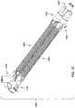
- FIG. 1Ais an elevational view of an example embodiment of a heated respiratory hose assembly.
- FIG. 1Bis a perspective view of the heated respiratory hose assembly of FIG. 1A showing details of electrical connectors thereof.
- FIG. 1Cis another perspective view of the heated respiratory hose assembly of FIG. 1A .
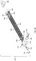
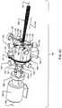
- FIG. 1Dis an exploded perspective view of the heated respiratory hose assembly of FIG. 1A showing details of the electrical connectors thereof and details of the coupling of hoses to hose fittings thereof.
- FIG. 1Eis another exploded perspective view of the heated hose assembly of FIG. 1A .
- FIG. 2Ais a block diagram of heated respiratory hose assembly of FIG. 1A showing details of the flow of respiratory gases therethrough and the monitoring of flow and temperature thereof.
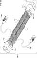
- FIG. 2Bis a perspective view of the inspiratory hose assembly of the heated respiratory hose assembly of FIG. 1A showing details of a sensor harness that is to be connected thereto.
- FIG. 2Cis a perspective view of the inspiratory inlet fitting of the inspiratory hose assembly of FIG. 2B showing features of the inspiratory inlet fitting to aid in correctly connecting a flow sensor of the sensor harness to enable correct operation thereof.
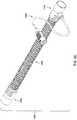
- FIG. 3Ais an exploded perspective view of an alternate embodiment of a heated respiratory hose assembly.
- FIG. 3Bis a perspective view of another alternate embodiment of a heated respiratory hose assembly.
- FIG. 3Cis a perspective view of the inspiratory hose assembly of still another embodiment of a heated respiratory hose assembly.
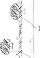
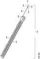
- FIG. 4Ais a cross-sectional view of a portion of one of the hoses of any of the embodiments of heated respiratory hose assembly of any of FIG. 1A, 3A, 3B or 3C showing details of the wall and support helix thereof.
- FIG. 4Bis a combination of perspective and cross-sectional views of a portion of the support helix of the hose of FIG. 4A showing details of the heating wires incorporated therein.
- FIG. 4Cis a perspective view of components of a hose making apparatus that may be adapted to make the hose of FIG. 4A .
- FIG. 4Dis a block diagram of components of a hose making apparatus that has been adapted to make the hose of FIG. 4A .
- FIG. 4Eis a cross-sectional view of a portion of the hose of FIG. 4A during the making thereof, and showing details of combining the support helix and wall thereof.
- FIG. 4Fis another cross-sectional view of the portion of the hose shown in FIG. 4E during the making thereof, and showing details of the bonding of the support helix to the wall thereof and of the drawing of the heating wires thereof toward the interior of the hose.
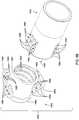
- FIG. 5Ais a perspective view a hose fitting and corresponding undermold coupling of any of the embodiments of heated respiratory hose assembly of any of FIG. 1A, 3A, 3B or 3C showing details of the features of one of the hose fittings and corresponding undermold coupling that are used to couple each to the other, and that are used to couple the undermold coupling to an end of one of the hoses.
- FIG. 5Bis another perspective view of the hose fitting and corresponding undermold coupling of FIG. 5A showing details of the manner in which features of each are used to coupled each to the other.
- FIG. 5Cis an elevational view of the hose fitting and corresponding undermold coupling of FIG. 5A prior to the coupling of each to the other.
- FIG. 5Dis a cross-sectional view of the hose fitting and corresponding undermold coupling of FIG. 5A during the coupling of one to the other.
- FIG. 5Eis another cross-sectional view, similar to FIG. 5D , of the hose fitting and corresponding undermold coupling of FIG. 5A during the coupling of one to the other.
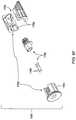
- FIG. 6Ais a partial perspective view of the inspiratory hose assembly of the heated respiratory hose assembly of FIG. 1A showing details of the electrical connection of an unwound end of the support helix of the hose thereof to an electrical connector carried within a plug within a hose fitting thereof.
- FIG. 6Bis another partial perspective view of the inspiratory hose assembly of FIG. 6A showing further details of the electrical connection of the unwound end of the support helix to the electrical connector.
- FIG. 6Cis a partial perspective view of the expiratory hose assembly of the heated respiratory hose assembly of FIG. 1A showing details of the electrical connection of an unwound end of the support helix of the hose thereof to an electrical connector carried within a plug within a hose fitting thereof.
- FIG. 6Dis an exploded perspective view of the combination of the plug and electrical connector of the inspiratory hose assembly of FIGS. 6A and 6B showing details of the manner in which the plug may be assembled from multiple pieces around the electrical connector.
- FIG. 6Eis a perspective view of the plug of the inspiratory hose assembly of FIGS. 6A and 6B showing details of the shaping of the plug improve the flow of respiratory gases through the inspiratory hose assembly.
- FIG. 6Fis an exploded perspective view of the combination of the plug and electrical connector of the expiratory hose assembly of FIG. 6C showing details of the manner in which the plug may be assembled from multiple pieces around the electrical connector.
- FIG. 6Gis a perspective view of the plug of the expiratory hose assembly of FIG. 6C showing details of the shaping of the plug improve the flow of respiratory gases through the inspiratory hose assembly.
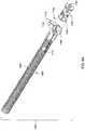
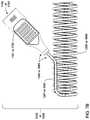
- FIG. 7Ais a partial elevational view of either the inspiratory hose assembly or the expiratory hose assembly of the embodiment of the heated respiratory hose assembly of FIG. 3B .
- FIG. 7Bis another partial elevational view of either the inspiratory hose assembly or the expiratory hose assembly of the embodiment of the heated respiratory hose assembly of FIG. 3B showing details of the manner in which the support helix is shaped and positioned within a hose fitting as part of forming a pigtail.
- FIG. 7Cis a combination of perspective and cross-sectional views of a portion of a pigtail of one of the hoses of either of the embodiments of heated respiratory hose assembly of any of FIG. 3B or 3C showing details of the formation of the pigtail from a portion of an unwound end of a support helix.
- FIGS. 1A through 1Etaken together, depict aspects of a novel heated respiratory hose assembly 1000 that addresses many of the shortcomings of prior art assemblies, including those discussed above.
- the heated respiratory hose assembly 1000may include two sub-assemblies, specifically an inspiratory hose assembly 1002 by which respiratory gases may be conveyed from a medical device to a patient to breathe in, and an expiratory hose assembly 1006 by which respiratory gases breathed out by the patient may be conveyed back to the medical device.
- This circular flowis also conceptually depicted in FIG. 2A .
- the inspiratory hose assembly 1002includes an inspiratory inlet fitting 1100 for connection to a medical device 990 (e.g., a ventilator or CPAP device), an inspiratory outlet fitting 1300 for connection to a parallel Y-fitting 1400 at the patient end, and an inspiratory hose 1200 to convey respiratory gases received by the inspiratory inlet fitting 1100 from the medical device 990 and to the inspiratory outlet fitting 1300 to be conveyed onward to the patient through the parallel Y-fitting 1400 .
- a medical device 990e.g., a ventilator or CPAP device
- an inspiratory outlet fitting 1300for connection to a parallel Y-fitting 1400 at the patient end
- an inspiratory hose 1200to convey respiratory gases received by the inspiratory inlet fitting 1100 from the medical device 990 and to the inspiratory outlet fitting 1300 to be conveyed onward to the patient through the parallel Y-fitting 1400 .
- the expiratory hose assembly 1006includes an expiratory inlet fitting 1500 for connection to the parallel Y-fitting 1400 at the patient end, an expiratory outlet fitting 1700 for connection to the medical device 990 , and an expiratory hose 1600 to convey respiratory gases received by the expiratory inlet fitting 1500 from the patient through parallel Y-fitting 1400 and to the expiratory outlet fitting 1700 to be conveyed onward to the medical device 990 .
- the parallel Y-fitting 1400may connect the heated respiratory hose assembly 1000 to a face mask 940 , an endotracheal tube 940 , a tracheostomy stoma 940 (see FIG. 2A ) or other component.
- FIGS. 1B and 1Cprovide a perspective view of one embodiment of the heated respiratory hose assembly 1000 in which the inspiratory inlet fitting 1100 and the expiratory outlet fitting 1700 are both implemented with 120-degree Y-fittings in which there is both a straight-through path for either gases or wiring to pass from the hoses 1200 and 1600 , respectively, and an angled path that branches off from the straight-through path at a 120-degree angle relative to the connections to the hoses 1200 and 1600 , respectively.
- FIGS. 1D and 1Eprovide an exploded perspective view of this embodiment.
- one of the connections of each of the Y-fittings 1100 and 1700is occupied by a plug 1180 and 1780 that carries an electrical connector 1190 and 1790 , respectively.
- the straight-through connection(relative to the connection to the inspiratory hose 1200 ) is occupied by the plug 1180 that carries the electrical connector 1190 by which electric power is able to be provided to a pair of heating wires incorporated into the support helix of the inspiratory hose 1200 , as will be explained in greater detail.
- the 120-degree connection(relative to the connection to the expiratory hose 1600 ) is occupied by the plug 1780 that carries the electrical connector 1790 by which electric power is able to be provided to a pair of heating wires incorporated into the helix of the expiratory hose 1600 , as will also be explained in greater detail.
- FIGS. 2A through 2Cdepict aspects of the use of sensors with at least the inspiratory hose assembly 1002 of the heated respiratory hose assembly 1000 to monitor the flow and/or temperature of at least respiratory gases from the medical device 990 to the patient.
- the inspiratory inlet fitting 1100may additionally include a flow sensor port 1110 formed through a portion of the wall of the inspiratory inlet fitting 1100 .
- the flow sensor port 1110provides an opening into the inspiratory interior of the inlet fitting 1100 through which a flow sensor 910 of a sensor harness 902 is able to be inserted to continually confirm the flow of respiratory gases from the medical device 990 and toward the patient at the patient end.
- the flow sensor 910is directional in nature such that it must be installed within the flow sensor port 1110 in a correct orientation to function properly.
- the inspiratory outlet fitting 1300may additionally include a temperature sensor port 1330 formed through the wall of the inspiratory outlet fitting 1300 .
- the temperature sensor port 1330provides an opening into the interior of the inspiratory outlet fitting 1300 by which a temperature sensor 930 of the sensor harness 902 is able to be inserted to continually monitor the temperature of the respiratory gases output by the medical device 990 at a location towards the patient end (i.e., just before those respiratory gases are conveyed through the inspiratory outlet fitting 1300 and into the parallel Y-fitting 1400 to be conveyed onward to the patient).
- the inspiratory inlet fitting 1100may carry a port plug 1112 that may be used to close and seal the flow sensor port 1110 in situations where at least the inspiratory hose assembly 1002 is used without the flow sensor 910 installed within the flow sensor port 1110 .
- the inspiratory outlet fitting 1300may carry a port plug 1332 that may similarly be used to close and seal the temperature sensor port 1330 in situations where at least the inspiratory hose assembly 1002 is used without the temperature sensor 930 installed within the temperature sensor port 1330 .
- the port plugs 1112 and 1332may be carried by the hose fittings 1100 and 1300 , respectively, by being attached thereto with elongate stretches of the rigid plastics material of the hose fittings 1100 and 1300 that are long and thin enough as to be sufficiently flexible that the port plugs 1112 and 1332 are able to be maneuvered to and from the ports 1110 and 1330 , respectively, for a relatively limited number of times without the elongate stretches breaking.
- the flow sensor 910 and the temperature sensor 930may be physically connected by a length of cabling 920 of the sensor harness 902 that is meant to follow the length of the inspiratory hose 1200 , and by which signals of the temperature sensor 930 are conveyed toward the location of the flow sensor 910 .
- respiratory gases to be breathed in by a patientare conveyed from the medical device 990 , through the inspiratory inlet fitting 1100 , then the inspiratory hose 1200 , then the inspiratory outlet fitting 1300 , then the parallel Y-fitting 1400 , and then to the patient via still another component, such as a face mask 940 , an endotracheal tube 940 , a tracheostomy stoma 940 or other component.
- respiratory gases breathed out by the patientare conveyed from the patient through such a component (e.g., the face mask 940 , the tracheal tube 940 , the tracheostomy stoma 940 or other component), then the parallel Y-fitting 1400 , then the expiratory inlet fitting 1500 , then the expiratory hose 1600 , then the expiratory outlet fitting 1700 , and onward to the medical device 990 .
- a componente.g., the face mask 940 , the tracheal tube 940 , the tracheostomy stoma 940 or other component
- the medical device 990monitors the flow sensor 910 to ensure that respiratory gases to be breathed in by the patient are, in fact, output by the medical device 990 and into the inspiratory hose assembly 1002 of the heated respiratory hose assembly 1000 towards the patient. If a lack of flow and/or flow in a wrong direction is detected by the sensor 910 , then the medical device 990 may sound an alarm and/or provide some other audio and/or visual indication of the lack of flow and/or the incorrect direction of flow.
- the medical devicemonitors the temperature sensor 930 to ensure that the respiratory gases that reach the patient end of the inspiratory hose 1200 are of a correct temperature, both to prevent condensation within the inspiratory hose 1200 , and for the health of the patient.
- the directional nature of the flow sensor 910requires correct installation of the flow sensor 910 within the interior of the inspiratory inlet fitting 1100 to ensure that it is caused to sense the flow of respiratory gases towards the patient with a correct orientation. Otherwise, it may be that the flow sensor 910 is caused to at least attempt to detect a flow of respiratory gases in a direction opposite of the correct direction towards the patient.
- the inspiratory inlet fitting 1100may carry a flow sensor guide 1119 adjacent to the flow sensor port 1110 to cooperate with the shape of a portion of the exterior of the flow sensor 910 to aid in correctly positioning the flow sensor 910 relative to the flow sensor port 1110 and the interior of the inspiratory inlet fitting 1100 .
- the flow sensor port 1110may be formed to include a short tube-like portion with a bevel cut 1111 to interact with an orientation key 911 carried on a portion of the exterior of the flow sensor 910 to aid in correctly positioning the flow sensor 910 relative to the flow sensor port 1110 and the interior of the inspiratory inlet fitting 1100 .
- the medical device 990may selectively turn on and off the provision of electric power to the heating wires within the inspiratory hose 1200 and the expiratory hose 1600 to selectively apply heat thereto based on the temperature sensed by the temperature sensor 930 . More specifically, and as will be explained in greater detail, each of the hoses 1200 and 1600 may incorporate at least a pair of heating wires that may be connected to the medical device 990 at one end of each of the hoses 1200 and 1600 , and that may be soldered, crimped or otherwise electrically connected at the other end of each of the hoses 1200 and 1600 to form a separate closed loop of electric current through each of the hoses 1200 and 1600 .
- Some medical devices 990may turn on and off the provision of electric power to the heating wires of both hoses together. Indeed, some medical devices 990 may selectively provide the very same voltage from the very same power source to the heating wires of both hoses. However, it may be the case that each of the two hoses 1200 and 1600 are to be heated to different temperatures. Thus, the heating wires employed in the two hoses 1200 and 1600 may be of different resistances and/or have other differing characteristics to bring about such a difference in temperature. More specifically, it may be deemed desirable to heat the respiratory gases being conveyed to the patient through the inspiratory hose 1200 to a higher temperature than the respiratory gases being conveyed from the patient through the expiratory hose 1600 .
- the heating of gases conveyed to the patientmay be deemed of greater importance for such purposes as achieving a particular higher temperature to help the patient maintain a particular body temperature, aid in treating the patient for a particular respiratory illness, etc. Such heating of the gases conveyed to the patient would also be intended to prevent condensation from occurring within the inspiratory hose 1200 . In contrast, the heating of gases conveyed from the patient may be solely for the purpose of preventing condensation from occurring within the expiratory hose 1600 .
- FIGS. 3A through 3Cdepict another possible embodiment of the heated respiratory hose assembly 1000 in which other possible different versions (or combinations of versions) of the inspiratory inlet fitting 1100 and the expiratory outlet fitting 1700 may be used.
- FIG. 3Aprovides an exploded perspective view of an alternate embodiment of the heated respiratory hose assembly 1000 in which the inspiratory inlet fitting 1100 and the expiratory outlet fitting 1700 are both T-fittings, instead of the 120-degree Y-fittings depicted in FIGS. 1A through 1E .
- FIG. 3Bprovides a perspective view of another alternate embodiment of the heated respiratory hose assembly 1000 in which the inspiratory inlet fitting 1100 and the expiratory outlet fitting 1700 are both through-fittings, and from each of which a pigtail 1285 and 1685 emerges by which the electrical connection to the heating wires of the hoses 1200 and 1600 , respectively, are separately made.
- FIG. 3Cprovides a perspective view of the expiratory hose assembly 1006 of still another embodiment of the heated respiratory hose assembly 1000 in which at least the expiratory outlet fitting 1700 is a through-fitting from which the pigtail 1685 by which electrical connection is made to the heating wires of the expiratory hose 1600 emerges in a direction perpendicular to the direction from which the expiratory hose 1600 emerges.
- the pigtails 1285 and/or 1685 depicted in the embodiment of FIG. 3Bemerge from the hose respective fittings 1100 and/or 1700 in a direction that is parallel to (and alongside) the hoses 1200 and/or 1600 , respectively.
- the inspiratory inlet fitting 1100 and the expiratory outlet fitting 1700are of different types (e.g., one may be a Y-fitting and the other may be a T-fitting, or one may be a Y-fitting or T-fitting that carries a plug with an electrical connector and the other may be a through-fitting with a pigtail that carries another plug).
- the inspiratory inlet fitting 1100 and the expiratory outlet fitting 1700are of different types (e.g., one may be a Y-fitting and the other may be a T-fitting, or one may be a Y-fitting or T-fitting that carries a plug with an electrical connector and the other may be a through-fitting with a pigtail that carries another plug).
- FIGS. 4A through 4Ftaken together, depict various aspects of the making of the inspiratory hose 1200 and the expiratory hose 1600 , including aspects of forming the support helixes 1280 and 1680 thereof to include a pair of heating wires 1290 and 1690 , respectively.
- helixes 1280 and 1680are depicted as each incorporating a pair of heating wires 1290 and 1690 , respectively, other embodiments of the hoses 1200 and/or 1600 are possible in which different numbers of wires (whether heating wires, or not) may be incorporated into the helixes 1280 and/or 1680 , respectively, as well as other embodiments in which there may be multiple helixes that each carry one or more different wires (whether heating wires, or not).
- each of the hoses 1200 and 1600may include a wall 1270 and 1670 , respectively, that is physically supported by a corresponding one of the support helixes 1280 and 1680 .
- the support helixes 1280 and 1680may spirally wrap around the exterior of the walls 1270 and 1670 , respectively, in a manner that leaves a continuous helical stretch of the walls 1270 and 1670 between adjacent coils of the support helixes 1280 and 1680 that enable the hoses 1200 and 1600 , respectively, to be flexible enough to bend.
- spacing between adjacent coils of the support helixes 1280 and 1680may be of a distance selected to allow fold(s), curve(s) and/or convolution(s) to be formed in the continuous helical stretch of the walls 1270 and 1670 therebetween to enable the hoses 1200 and 1600 , respectively, to be axially stretched and compressed (i.e., lengthened or shortened along the depicted axis 101 ), as well as to bend.
- the heating wires 1290 and 1690may be positioned within the flexible plastics material of the support helixes 1280 and 1680 to bring them closer to the interior of the hoses 1200 and 1600 , respectively, than to the environment external thereto. In this way, much of the flexible plastics material that makes up the support helixes 1280 and 1680 is used as insulation to tend to cause the heat generated by the heating wires 1290 and 1690 to be radiated into the interiors of the hoses 1200 and 1600 , respectively, instead of being wasted by being radiated into the environment external to the hoses 1200 and 1600 .
- each individual heating wire 1290 and 1690may incorporate a conductor 1291 and 1691 , and an individual insulator 1292 and 1692 in addition to the insulation provided by the flexible plastics material of the support helix 1280 and 1680 , respectively.
- the heating wire 1290 and 1690may be a variant of magnet wire or similar wire with a selected resistance where the insulator 1292 and 1692 , respectively, may be one or more layers of polymer or other type of film.
- the insulators 1292 and 1692may be selected to be capable of resisting temperatures expected to be encountered during heating of the hoses 1200 and 1600 , respectively, but to not be capable resisting temperatures typically encountered during soldering such that electrical connections may be made to the wires 1290 and 1690 using any of a variety of soldering techniques without requiring stripping of the insulation 1292 and 1692 , respectively, in preparation therefor.
- each of the hoses 1200 and 1600may be formed using a modified variant of a typical hose manufacturing apparatus 100 .
- a hose manufacturing apparatus 100may incorporate a set of rotating rollers 110 that may be canted in adjustable orientations relative to each other and relative to the axis 100 to form a hose therearound from one or more spirally wound extruded lengths of plastics material.
- such hose formingtypically entails wrapping at least one extruded length of webbing material for the wall of the hose and at least one extruded length of a support bead for at least one support helix of the hose.
- a single extrusion of material that combines the webbing and support beadmay be used, as will also be familiar to those skilled in the art.
- An example of such hose manufacturing apparatusis disclosed in U.S. Pat. No. 9,505,164 issued Nov. 29, 2016 to Carl J. Garrett, which is incorporated herein by reference in its entirety, and from which FIG. 1 was copied to provide 4 C of this present application.
- hose making on which the making of the hoses 1200 or 1600 may also be basedare disclosed in U.S. Pat. No. 9,308,698 issued Apr. 12, 2016 to Martin E. Forrester, and U.S. Pat. No. 9,556,878 issued Jan. 31, 2017 to Carl J. Garrett, each of which is incorporated herein by reference in their entireties.
- a typical hose making apparatus 100may be modified to enable the extrusion of the flexible plastics material of the support helixes 1280 and 1680 around the heating wires 1290 and 1690 , respectively, prior to the winding of the support helixes 1280 and 1680 onto the rollers 110 .
- each of the heating wires 1290 and/or 1690 around which the plastic material of the helixes 1280 and/or 1680 , respectively, is extrudedmay be tensioned (either at the spool from which each of the heating wires 1290 and/or 1690 are unwound, or with a separate tensioning device between the spool and the extruder 107 b ) to cause a “drawing down” of each of the heating wires 1290 and/or 1690 through the material of the support helixes 1280 and/or 1680 , and closer towards the wall 1270 and/or 1670 as the hoses 1200 and/or 1600 , respectively, are made.
- the heating wires 1290 or 1690may initially centered within the extruded plastics material.
- the tensioner(s) 108may exert tension on the heating wires 1290 or 1690 to cause the heating wires 1290 or 1690 to be pulled radially inwardly toward the central axis 101 of the hose 1200 or 1600 being formed.
- heating wires 1290 or 1690may migrate within the flexible plastics material of the support helix 1280 or 1680 (again, while still somewhat molten and compliant) to a position within that plastics material that is closer to the interior of the hose 1200 or 1600 , respectively, being formed than their initially centered position.
- FIG. 4Eas the wall 1270 or 1670 of one of the hoses 1200 or 1600 is formed on the rollers 110 of the hose making apparatus 100 , a portion of the support helix 1280 or 1680 is laid down upon the external surface of the wall 1270 or 1670 , respectively.
- the cross-section of the length of extruded material from which the wall 1270 or 1670 is formedmay include a pair of radially outwardly projecting guides to aid in guiding the support helix 1280 or 1680 into its proper position on the exterior surface of the wall 1270 or 1670 , respectively.
- the aforedescribed tensioncauses inward migration of the heating wires 1290 or 1690 within the flexible (and still somewhat molten and compliant) plastics material of that portion of the support helix 1280 or 1680 toward the external surface of the wall 1270 or 1670 (which may be less molten or no longer molten, which may be used to stop the migration at the external surface of the wall 1270 or 1670 ), toward the interior of the hose 1200 or 1600 , and toward the central axis 101 of the hose 1200 or 1600 , respectively.
- This technique of causing a radially inward draw downmay be deemed preferable to attempting to position the heating wires 1290 and/or 1690 within the cross-sections of the extrusions of the helixes 1280 and/or 1680 at such locations during extrusion.
- This technique of causing a radially inward draw downmay also provide the flexibility to allow variations in placement of the heating wires 1290 and/or 1690 further radially inward and/or further radially outward within the cross-sections of the helixes 1280 and/or 1680 , respectively, as part of creating different variants of the hoses 1200 and/or 1600 that may have different heating characteristics (and/or other characteristics that may be influenced by placement of the heating wires 1290 and/or 1690 within the helixes 1280 and/or 1680 , respectively).
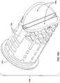
- FIGS. 5A through 5Etaken together, depict various aspects of coupling the expiratory inlet fitting 1500 to an undermold coupling 1800 , and thereby, to one end of the expiratory hose 1600 .
- the expiratory inlet fitting 1500may be coupled to one end of the expiratory hose 1600 via the depicted undermold coupling 1800 interposed between a portion of the outer surface of that end of the expiratory hose 1600 and a portion of the inner surface of a hose interface 1580 of the expiratory inlet fitting 1500 .
- the undermold coupling 1800may include a tubular portion 1881 having a cylindrical tubular shape that defines a passage therethrough. At one end of the tubular shape of the tubular portion 1881 may be a ring 1883 that extends radially outward from the cylindrical tubular shape of the tubular portion 1881 . Extending from the ring 1883 (or form another portion of the external surface of the tubular portion 1881 ) may be one or more gratings 1885 that may be defined by one or more parallel elongate portions of the flexible plastics material of the undermold coupling 1800 that define one or more parallel slots 1886 . Each of the elongate portions of the material that define one of the one or more gratings 1885 may be curved to allow each to extend in a manner that follows the curve of the cylindrical shape of the tubular portion 1881 .
- Each grating 1885may be supported by, and attached to, the rest of the structure of the undermold coupling 1800 (e.g., connected to the ring portion 1883 , as depicted) by a pair of grating supports 1884 that may cooperate with the grating 1885 to create what may visually resemble a ladder.
- the grating supportsmay tend to support the one or more gratings 1885 at a location and in an orientation that causes each grating 1885 to extend alongside and in parallel with a portion of the external surface of the tubular portion 1881 .
- each grating 1885is so positioned by one or more of the grating supports 1884 , inwardly facing surfaces 1888 of each of the one or more curved elongate portions of flexible plastics material that defines each of the gratings 1885 may tend to be positioned in contact with the portion of the external surface of the tubular portion 1881 that its corresponding grating 1885 overlies.
- the grating supports 1884may each be flexible enough to allow each of the gratings 1885 to be pulled away from its position extending alongside and parallel with a portion of the external surface of the tubular portion 1881 (thereby pulling the inwardly facing surfaces thereof out of contact with the external surface of the tubular portion 1881 .
- the hose interface of the expiratory inlet fitting 1500may incorporate one or more gratings 1586 that are meant to correspond to the one or more gratings 1885 carried by the undermold coupling 1800 .
- Each of the one or more gratings 1586may be defined by one or more parallel elongate portions of the rigid plastics material of the expiratory inlet fitting 1500 that define one or more parallel slots 1585 that may have the appearance of a set of one or more vent slots formed through the wall of the expiratory inlet fitting 1500 .
- Each of the elongate portions of the material that define one of the one or more gratings 1586may be curved to allow each to extend in a manner that parallels the curve of the cylindrical shape of the tubular portion 1881 .
- the one or more parallel elongate portions of the material of the expiratory fitting 1500 that define one of the one or more gratings 1586 , and the one or more slots 1585 defined thereby,may be intersected by one or more troughs 1584 formed in the cylindrical external surface of the expiratory inlet fitting 1500 to receive a corresponding one or more of the grating supports 1884 .
- the undermold coupling 1800may include threads 1882 formed on the inner surface of the tubular portion 1881 to receive and surround the external surface of one end of the expiratory hose 1600 in a manner that engages the wall 1670 and the support helix 1680 thereof as if the wall 1670 and helix 1680 , together, formed matching threads as a mechanism by which the undermold coupling 1800 may grip that end of expiratory hose 1600 within the tubular portion 1881 .
- the tubular portion 1881 of the undermold coupling 1800may be threaded onto an end of the expiratory hose 1600 .
- each grating 1885 of the undermold coupling 1800may be pulled away from the tubular portion 1881 (relying on the flexibility of the grating supports 1884 to act somewhat like hinges) and caused to extend over exterior portions of the expiration inlet fitting 1500 in the vicinity of the hose interface 1580 . With each grating 1885 so positioned over its corresponding grating 1586 , the grating 1885 may then be allowed to return to a position alongside and parallel to the external surface of the tubular portion 1881 of the undermold coupling 1800 .
- each of the gratings 1885allowed to return to a position alongside and parallel to the external surface of the tubular portion 1881 while each of the gratings 1885 is positioned over its corresponding grating 1586 , the corresponding ones of the one or more gratings 1885 and 1586 are caused to intermesh in a manner that mechanically locks the undermold coupling 1800 within the hose interface 1580 .
- each of the elongate portions of a grating 1885 of the undermold coupling 1800extends into a corresponding slot 1585 defined by the corresponding grating 1586 of the expiratory inlet fitting 1500 , and each of the elongate portions of that corresponding grating 1586 extends into a corresponding slot 1886 defined by the grating 1885 .
- heatmay be applied to soften at least the undermold coupling 1800 to cause the inwardly facing surfaces 1888 of those portions of the one or more gratings 1885 that are once again in contact with the external surface of the tubular portion 1881 to become bonded to the exterior of the tubular portion 1881 , as most clearly depicted in FIG. 5E .
- Such heatingmay also more broadly bond the materials of the thread-like exterior of the end of the expiratory hose 1600 (onto which the undermold coupling 1800 is threaded) to surfaces of the threads 1882 formed within the undermold coupling 1800 , and such heating may also more broadly bond the material of the exterior surface of the tubular portion 1881 of the undermold coupling 1800 to the interior surface of the expiration inlet fitting 1500 into which the undermold coupling 1800 is inserted. As a result, gas-tight seals may be formed among these components.
- an end of the expiratory hose 1600may be inserted into the hose interface 1580 of the expiratory inlet fitting 1500 without an undermold coupling 1800 threaded thereon.
- the flexible material of the undermold coupling 1800in molten form, may be injected into one or more of the slots 1585 of one or more gratings 1586 of the hose interface 1580 to fill the space between the thread-like external surface of that end of the expiratory hose 1600 and the interior surface of the hose interface 1580 to form the undermold coupling 1800 in place therebetween, as well as to fill each of the slots 1585 .
- the flexible material of the undermold coupling 1800in molten form, may be injected therein between the expiratory hose 1600 and the edge of the interior surface of the hose interface 1580 , where the expiratory hose 1600 enters into the hose interface 1580 , to form the undermold coupling 1800 in place, as well as to fill each of the slots 1585 from within the interior of the hose interface 1580 .
- the molten form of the material of the undermold coupling 1800may bond to the materials of thread-like external surface at the end of the expiratory hose 1600 and the interior surface of the hose interface 1580 to form a gas-tight seal therebetween.
- FIGS. 5A through 5Edepict these features in a manner that is focused on the connection of an end of the expiratory hose 1600 to the expiratory inlet fitting 1500
- the very same coupling arrangement just describedmay be employed to couple the other end of the expiratory hose 1600 to the expiratory outlet fitting 1700 , and/or one or both ends of the inspiratory hose 1200 to one or both of the inspiratory inlet fitting 1100 and the inspiratory outlet fitting 1300 .
- FIGS. 5A through 5Edepict these features in a manner that is focused on the
- multiple ones of the undermold coupling 1800may be employed to couple each of the fittings 1100 and 1300 to opposite ends of the inspiratory hose 1200 , and to couple each of the fittings 1500 and 1700 to opposite ends of the expiratory hose 1600 .
- FIGS. 6A through 6Gtaken together, depict various aspects of incorporating the plug 1180 or 1780 incorporating the electrical connector 1190 or 1790 into one of the three connections provided by the inspiratory inlet fitting 1100 or the expiratory outlet fitting 1700 , respectively. Also depicted are various aspects of the direct electrical coupling of the heating wires 1290 or 1690 to the electrical connector 1190 or 1790 , respectively.
- FIGS. 6A and 6Bdepicts a subset of the components of the inspiratory hose assembly 1002 toward the end thereof that is to be connected to the medical device 990 . More precisely, FIGS. 6A and 6B each depict the path followed by the support helix 1280 within the inspiratory hose 1200 and where an end of the inspiratory hose 1200 is coupled to the inspiratory inlet fitting 1100 . The wall 1270 of the inspiratory hose 1200 has been omitted in both of these views for purposes of visual clarity. Additionally, in FIG. 6B , both the plug 1180 and the insulating shroud portion of the electrical connector 1190 have been omitted, also for purposes of visual clarity.
- a relatively short portion of the support helix 1280is unwound from its helical path within the inspiratory hose 1200 and is employed as an electrical cable to bring the heating wires 1290 therein to the electrical connector 1190 within the plug 1180 .
- a relatively short portion of the support helix 1280is pulled out of the end of the inspiratory hose 1200 (i.e., unwound therefrom) where that end is inserted into the inspiratory inlet fitting 1100 , and straightened to at least some degree for use as an electrical cable to bring the heating wires 1290 therein directly to the electrical connector 1190 .
- This unwinding of the relatively short portion of the support helix 1280may be performed prior to the threading of the depicted undermold coupling 1800 onto the end of the inspiratory hose 1200 that is to be inserted into the inspiratory inlet fitting 1100 .
- the relatively short unwound portion of the support helix 1280extends beyond the end of the inspiratory hose 1200 onto which the undermold coupling 1800 is threaded, thereby emerging from within the undermold coupling 1800 and extending further into the interior of the inspiratory inlet fitting 1100 than the end of the inspiratory hose 1200 onto which the undermold coupling 1800 is threaded.
- the end of the relatively short portion of the support helix 1280 that extends toward the electrical connector 1190may be partly stripped away to remove at least enough of the flexible plastics material of the support helix 1280 to expose enough of the heating wires 1290 therein to enable forming an electrical connection with the contacts 1199 of the electrical connector 1190 .
- the plastics material of the support helix 1280may be stripped away in a manner that may be akin to procedures often used in preparing conventional multi-conductor cables for the connection of the individual wires therein to contacts of an electrical connector or other electrical device.
- typical wire stripping techniquesmay be employed to gain access to each of the heating wires 1290 , and then the conductor 1299 (see FIG.
- each of the heating wires 1290may be soldered to a soldering tab of one of the electrical contacts 1199 of the electrical connector 1190 .
- a sheathe.g., heatshrink tubing that may be sleeved over the relatively short unwound portion of the support helix 1280
- part of that sheathmay also be similarly stripped away using typical wire stripping techniques.
- the conductor 1299 of each of the heating wires 1290may be sheathed within an individual insulator 1291 that is selected to be thermally resistant to the temperatures expected to be encountered during heating of the inspiratory hose 1200 , but not to the temperatures expected to be encountered during soldering, thereby eliminating the need to strip each of the conductors 1299 of their individual insulators 1291 prior to soldering each of the conductors 1299 to a soldering tab of one of the electrical contacts 1199 .
- portions of the wall 1270that extend between adjacent coils of the support helix 1280 that are included in the relatively short portion thereof may be trimmed away.
- the relatively short unwound portion of the support helix 1280may be heated to soften the flexible plastics material thereof (i.e., to relax the molecules of the flexible plastics material thereof) to aid in straightening it out from its original helical path within the inspiratory hose 1200 (i.e., causing the molecules of the flexible plastics material of the relatively short portion of the support helix 1280 to adopt a straightened path as a new resting state).
- the actual length of the relatively short portion of the support helix 1280 that emerges from the undermold coupling 1800 and extends further into the interior of the inspiration inlet fitting 1100may be based, at least in part, on the dimensions of the inspiration inlet fitting 1100 . More specifically, the length may be selected based on the length needed to extend from the undermold coupling 1800 and to the electrical connector 1190 , and may include a predetermined additional length needed to allow manufacturing personnel sufficient physical access to solder the conductors 1299 of the heating wires 1290 to the soldering tabs of the electrical contacts 1199 , as earlier described.
- FIG. 6Cdepicts a subset of the components of the expiratory hose assembly 1006 toward the end thereof that is to be connected to the medical device 990 . More precisely, FIG. 6C depicts the path followed by the support helix 1680 within the expiratory hose 1600 and where an end of the expiratory hose 1600 is coupled to the expiratory outlet fitting 1600 .
- the wall 1670 of the expiratory hose 1600 , the plug 1780 and the insulating shroud portion of the electrical connector 1790have all been omitted for purposes of visual clarity.
- a relatively short portion of the support helix 1680is unwound from its helical path within the expiratory hose 1600 and is employed as an electrical cable to bring the heating wires 1690 therein to the electrical connector 1790 within the plug 1780 (again, not shown).
- a relatively short portion of the support helix 1680is pulled out of the end of the expiratory hose 1600 (i.e., unwound therefrom) where that end is inserted into the expiratory outlet fitting 1700 , and straightened to at least some degree for use as an electrical cable to bring the heating wires 1690 therein directly to the electrical connector 1790 .
- this unwinding of the relatively short portion of the support helix 1680may be performed prior to the threading of another of the undermold couplings 1800 onto the end of the expiratory hose 1600 that is to be inserted into the expiratory outlet fitting 1700 .
- the relatively short portion of the support helix 1680extends beyond the end of the expiratory hose 1600 onto which the undermold coupling 1800 is threaded, thereby emerging from within the undermold coupling 1800 and extending further into the interior of the expiratory outlet fitting 1700 than the end of the expiratory hose 1600 onto which the undermold coupling 1800 is threaded.
- the end of the relatively short unwound portion of the support helix 1680 that extends toward the electrical connector 1790may also be partly stripped away to remove at least enough of the flexible plastics material of the support helix 1680 to expose enough of the heating wires 1690 therein to enable forming an electrical connection with the contacts 1199 of the electrical connector 1190 .
- thismay also be done using typical wire stripping techniques, and again, if the stripped-away part of the unwound portion of the support helix 1680 is additionally covered in a sheath (e.g., heatshrink tubing), part of that sheath may also be similarly stripped away using typical wire stripping techniques.
- a sheathe.g., heatshrink tubing
- portions of the wall 1670that extend between adjacent coils of the support helix 1680 that are included in the relatively short portion thereof may be trimmed away.
- the relatively short portion of the support helix 1680may be heated to soften the flexible plastics material thereof to aid in straightening it out from its original helical path within the expiratory hose 1600 .
- the actual length of the relatively short portion of the support helix 1680 that emerges from the undermold coupling 1800 and extends further into the interior of the expiration outlet fitting 1700may be based, at least in part, on the dimensions of the expiration outlet fitting 1700 . More specifically, the length may be selected based on the length needed to extend from the undermold coupling 1800 and to the electrical connector 1790 , and may include a predetermined additional length needed to allow manufacturing personnel sufficient physical access to solder the conductors 1699 of the heating wires 1690 to the soldering tabs of the electrical contacts 1799 .
- Such use of a portion of the support helixes 1280 and/or 1680advantageously avoids the creation of electrical terminations where a transition is made between the heating wires 1290 and/or 1690 of the support helixes 1280 and/or 1680 to non-heating wires that travel a relatively short distance within the fittings 1100 and/or 1300 to electrically couple the heating wires 1290 and/or 1690 to the electrical connectors 1190 and/or 1790 , respectively.
- electrical terminations to transition between heating and non-heating wirescan be a source of potentially dangerous electrical failures.
- FIGS. 6D and 6Etaken together, depict various features of the plug 1180 and the electrical connector 1190 carried therein.
- the plug 1180may be formed from multiple separately fabricated plastic components, including the depicted face portion 1181 and the depicted pair of “clamshell” portions 1182 .
- much of the electrical connector 1190(with its electrical contacts 1199 installed therein, and already soldered to the conductors 1299 of the heating wires 1290 of the support helix 1280 ) may be enclosed between the two clamshell portions 1182 , which may be fastened to each other in any of a variety of ways.
- a portion of the support helix 1280 adjacent the electrical connector 1190may also be enclosed between the two clamshell portions 1182 .
- the face portion 1181may then be molded over the assembled pair of the clamshell portions 1182 with the electrical connector 1190 enclosed between the clamshell portions 1182 .
- portions of the plastics material of the face portion 1181while in a molten state, may fill various convolutions formed within each of the two clamshell portions 1182 to further bond them together.
- the face portion 1181may also seal spaces between the two clamshell portions 1182 within which the electrical connector 1190 is held, as well as the portion of the support helix that is also enclosed therebetween.
- the electrical connections between the conductors 1299 of the heating wires 1290 and the electrical contacts 1199 of the electrical connector 1190may be entirely enclosed to seal and protect those connections against moisture present in the respiratory gases conveyed through the inspiratory inlet fitting 1100 to thereby prevent corrosion, etc.
- the entire plug 1180may simply be molded around the electrical connector 1190 .
- a portion of the support helix 1280 adjacent the electrical connector 1190may also be enclosed within such a molded form of the plug 1180 .
- the portion of the plug 1180 that extends furthest into the inspiration inlet fitting 1100may be shaped to cooperate with interior surface portions of the inspiration inlet fitting 1100 to present a relatively unobstructed path for the flow of respiratory gases through the inspiration inlet fitting 1100 with relatively smooth surfaces encountered by the respiratory gases throughout that path. More precisely, and as best seen in FIG. 6E , as well as in FIGS.
- the portion of the plug 1180 that extends furthest into the inspiration inlet fitting 1100may be provided with a concave surface 1183 that serves to define part of such a relatively unobstructed path with smooth surfaces for the flow of respiratory gases.
- FIGS. 6F and 6Gtaken together, depict similar features of the plug 1780 and the electrical connector 1790 carried therein.
- the plug 1780may be formed from multiple separately fabricated plastic components, including the depicted face portion 1781 and the depicted pair of clamshell portions 1782 .
- much of the electrical connector 1790(with its electrical contacts 1799 installed therein, and already soldered to the conductors 1699 of the heating wires 1690 of the support helix 1680 ) may be enclosed between the two clamshell portions 1782 , which may be fastened to each other in any of a variety of ways.
- a portion of the support helix 1680 adjacent the electrical connector 1790may also be enclosed between the two clamshell portions 1782 .
- the face portion 1781may then be molded over the assembled pair of the claims clamshell portions 1782 to form the plug 1780 with the electrical connector 1790 sealed in place therein in a manner similar to what has been previously described in reference to the plug 1180 .
- the entire plug 1780may simply be molded around the electrical connector 1790 .
- a portion of the support helix 1680 adjacent the electrical connector 1790may also be enclosed within such a molded form of the plug 1780 .
- the portion of the plug 1780 that extends furthest into the expiration outlet fitting 1700may be shaped to cooperate with interior surface portions of the expiration outlet fitting 1700 to present a relatively unobstructed path for the flow of respiratory gases through the expiration outlet fitting 1700 with relatively smooth surfaces encountered by the respiratory gases throughout that path. More precisely, and as best seen in FIG. 6G , as well as in FIGS.
- the portion of the plug 1780 that extends furthest into the inspiration inlet fitting 1700may be provided with a concave surface 1783 that serves to define part of such a relatively unobstructed path with smooth surfaces for the flow of respiratory gases.
- the electrical connectors 1190 and 1790may be provided with differing physical shapes as a keying mechanism to prevent incorrect electrical connections between the medical device 990 and each of the heating wires 1290 and 1690 within the hoses 1200 and 1600 , respectively. More specifically, the electrical connector 1190 is depicted as being a so-called “monkey face” connector having a shape that includes three lobes in which two of the lobes are each occupied by one of the electrical contacts 1199 .
- the electrical connector 1790is depicted as having a more conventional elongate oval-like shape in which the electrical contacts 1799 are positioned toward opposite ends of the of the oval-like shape.
- this depicted combination of forms of the electrical connectors 1190 and 1790have become widely adopted for use in providing electric power for heating the hoses used with such medical devices.
- the conductors 1299 of the pair of heating wires 1290may be electrically connected to each other through crimping, soldering, etc., to form an electrical loop with the pair of heating wires 1290 through the support helix 1280 for heating the interior of the inspiration hose 1200 .
- the conductors 1699 of the pair of heating wires 1690may be similarly electrically connected to each other to form a separate electrical loop with the pair of heating wires 1690 through the support helix 1680 for separately heating the interior of the expiration hose 1600 .
- the medical device 990may operate each of these electrical loops separately and in different ways that may be selected to cause differing degrees of heating within each of the hoses 1200 and 1600 .
- the heating wires 1290 and 1690may be selected to have different resistances in recognition of such differences in the manner in which each may be used.
- FIGS. 7A through 7Cdepict various aspects of forming an electrical “pigtail” 1285 or 1685 from a portion of the support helix 1280 or 1680 for use in connecting the heating wires 1290 or 1690 to the medical device 990 to be provided with electrical power therefrom.
- FIGS. 7A through 7Cpresent embodiments of the use of a portion of the support helix 1280 or 1680 as an electrical cable to advantageously avoid the creation of a electrical terminations where a transition is made between the heating wires 1290 or 1690 , respectively, to non-heating wires.
- FIGS. 7A through 7Cdepict various aspects of forming an electrical “pigtail” 1285 or 1685 from a portion of the support helix 1280 or 1680 for use in connecting the heating wires 1290 or 1690 to the medical device 990 to be provided with electrical power therefrom.
- FIGS. 7A through 7Cpresent embodiments of the use of a portion of the support helix 1280 or 1680 as an electrical cable to advantageously avoid the creation
- the connector 1190 or 1790is carried within the plug 1180 or 1780 installed within the fitting 1100 or 1700 , respectively, in the embodiments of FIGS. 7A through 7C , the connector 1190 or 1790 is located in the environment external to the fitting 1100 or 1700 at the end of an electrical pigtail 1285 or 1685 , respectively.
- FIGS. 7A through 7Cdepicts a subset of the components of either the inspiratory hose assembly 1002 or the expiratory hose assembly 1006 toward the end thereof that is to be connected to the medical device 990 . More precisely, in each of FIGS. 7A through 7C , depictions of one of the undermold couplings 1800 , and of the wall 1270 or 1670 of the hose 1200 or 1600 has been omitted to enable the helical path of the support helix 1280 or 1680 , respectively, therein to be viewed more clearly. Additionally, in FIG. 7B , the depiction of either the inspiratory inlet fitting 1100 or the expiratory outlet fitting 1700 that is provided in FIG.
- 7Ais also omitted to provide an uninterrupted view of the transition of the support helix 1280 or 1680 from its helical path for purposes of heating the interior of the hose 1200 or 1600 to a relatively straightened path for purposes of being used as an electrical cable to convey the heating wires 1290 or 1690 thereof to the connector 1190 or 1790 .
- FIGS. 7A and 7Bas depicted, where an end of a portion of the inspiratory hose 1200 is inserted into a portion of the inspiratory inlet fitting 1100 , or where an end of a portion of the expiratory hose 1600 is inserted into a portion of the expiratory outlet fitting 1700 , a portion of the support helix 1280 or 1680 is unwound from its helical path within the inspiratory hose 1200 or 1600 and is employed as an electrical cable to bring the heating wires 1290 or 1690 therein to the electrical connector 1190 or 1790 at an end of the electrical pigtail 1285 or 1685 , respectively.
- a portion of the support helix 1280 or 1680is pulled out of the end of the hose 1200 or 1600 (i.e., unwound therefrom) where that end is inserted into the fitting 1100 or 1700 , respectively.
- the length of the unwound portion of the support helix 1280 or 1680may be determined, at least in part, by the intended length of the electrical pigtail 1285 or 1685 .
- the unwound portion of the support helix 1280 or 1680may then be straightened to at least some degree for use as an electrical cable.
- This unwinding of the portion of the support helix 1280may be performed prior to the threading of the depicted undermold coupling 1800 (again, not shown for purposes of visual clarity) onto the end of the hose 1200 or 1600 that is to be inserted into the fitting 1100 or 1700 , respectively.
- the unwound portion of the support helix 1280extends beyond the end of the 1200 or 1600 onto which the undermold coupling 1800 is threaded, thereby emerging from within the undermold coupling 1800 and extending further into the interior of the 1100 or 1700 than the end of the hose 1200 or 1600 , respectively, onto which the undermold coupling 1800 is threaded.
- the unwound portion of the support helix 1280 or 1680may then be fed through a channel and/or opening defined by a portion of the fitting 1100 or 1700 to be caused to extend into the environment external to the fitting 1100 or 1700 to serve as the core of the electrical pigtail 1285 or 1685 .
- the unwound portion of the support helix 1285 or 1685may be covered in a sheath 1281 or 1681 , at least where the unwound portion of the support helix 1285 or 1685 emerges from the fitting 1100 or 1700 , respectively, and into the environment external thereto.
- the sheath 1281 or 1681may cover at least part of the unwound portion of the support helix 1285 or 1685 within the fitting 1100 or 1700 .
- the sheath 1281 or 1681may be a length of heatshrink tubing that is sleeved over the unwound portion of the support helix 1285 or 1685 (at least the length thereof that is within the environment external to the fitting 1200 or 1600 ), and then heated to cause the cross-section of the heatshrink tubing to shrink radially inward toward the exterior of the unwound portion of the support helix 1285 or 1685 .
- Such an application of heatmay also be used to aid in the straightening of the unwound portion of the support helix 1280 or 1680 and/or to somewhat change the shape thereof to conform to the interior surface of the heatshrink tubing as the heatshrink tubing is caused to tightly surround the unwound portion of the support helix 1285 or 1685 , respectively (at least the length thereof that is within the environment external to the fitting 1200 or 1600 ).
- the end of the unwound portion of the support helix 1280 or 1680 that extends toward the electrical connector 1190 or 1790may be partly stripped away to remove at least enough of the flexible plastics material of the support helix 1280 or 1680 (and maybe also to strip away a portion of the sheath 1281 or 1681 ) to expose enough of the heating wires 1290 or 1690 therein to enable forming an electrical connection with the contacts 1199 or 1799 of the electrical connector 1190 or 1790 , respectively. Again, this may also be done using typical wire stripping techniques.
- portions of the wall 1270 or 1670that extend between adjacent coils of the support helix 1280 or 1680 that are included in the unwound portion thereof may be trimmed away.
Landscapes
- Engineering & Computer Science (AREA)
- Health & Medical Sciences (AREA)
- Mechanical Engineering (AREA)
- Life Sciences & Earth Sciences (AREA)
- Hematology (AREA)
- General Health & Medical Sciences (AREA)
- Biomedical Technology (AREA)
- Heart & Thoracic Surgery (AREA)
- Pulmonology (AREA)
- Veterinary Medicine (AREA)
- Animal Behavior & Ethology (AREA)
- Anesthesiology (AREA)
- Public Health (AREA)
- Emergency Medicine (AREA)
- Manufacturing & Machinery (AREA)
- Biophysics (AREA)
- Rigid Pipes And Flexible Pipes (AREA)
- Pipe Accessories (AREA)
Abstract
Description
Claims (20)
Priority Applications (7)
| Application Number | Priority Date | Filing Date | Title |
|---|---|---|---|
| US15/882,257US11052214B2 (en) | 2017-01-30 | 2018-01-29 | Heated respiratory hose wiring |
| CA3033944ACA3033944C (en) | 2017-01-30 | 2018-01-29 | Heated respiratory hose assembly |
| CA3053834ACA3053834C (en) | 2017-01-30 | 2018-01-29 | Heated respiratory hose assembly |
| PCT/IB2018/000134WO2018138581A1 (en) | 2017-01-30 | 2018-01-29 | Heated respiratory hose assembly |
| US16/506,989US11813403B2 (en) | 2017-01-30 | 2019-07-09 | Heated respiratory hose wiring |
| US16/920,718US11839719B2 (en) | 2017-01-30 | 2020-07-05 | Heated respiratory hose wiring |
| US18/536,950US20240115847A1 (en) | 2017-01-30 | 2023-12-12 | Heated respiratory hose support helix incorporating lumens |
Applications Claiming Priority (2)
| Application Number | Priority Date | Filing Date | Title |
|---|---|---|---|
| US201762499623P | 2017-01-30 | 2017-01-30 | |
| US15/882,257US11052214B2 (en) | 2017-01-30 | 2018-01-29 | Heated respiratory hose wiring |
Related Child Applications (1)
| Application Number | Title | Priority Date | Filing Date |
|---|---|---|---|
| US16/506,989Continuation-In-PartUS11813403B2 (en) | 2017-01-30 | 2019-07-09 | Heated respiratory hose wiring |
Publications (2)
| Publication Number | Publication Date |
|---|---|
| US20180214657A1 US20180214657A1 (en) | 2018-08-02 |
| US11052214B2true US11052214B2 (en) | 2021-07-06 |
Family
ID=62977000
Family Applications (4)
| Application Number | Title | Priority Date | Filing Date |
|---|---|---|---|
| US15/882,257Active2039-03-31US11052214B2 (en) | 2017-01-30 | 2018-01-29 | Heated respiratory hose wiring |
| US15/882,286AbandonedUS20180214658A1 (en) | 2017-01-30 | 2018-01-29 | Heated respiratory hose connection |
| US15/882,313Active2038-11-24US10792454B2 (en) | 2017-01-30 | 2018-01-29 | Heated respiratory hose assembly |
| US18/122,669PendingUS20230218851A1 (en) | 2017-01-30 | 2023-03-16 | Heated respiratory hose connection |
Family Applications After (3)
| Application Number | Title | Priority Date | Filing Date |
|---|---|---|---|
| US15/882,286AbandonedUS20180214658A1 (en) | 2017-01-30 | 2018-01-29 | Heated respiratory hose connection |
| US15/882,313Active2038-11-24US10792454B2 (en) | 2017-01-30 | 2018-01-29 | Heated respiratory hose assembly |
| US18/122,669PendingUS20230218851A1 (en) | 2017-01-30 | 2023-03-16 | Heated respiratory hose connection |
Country Status (4)
| Country | Link |
|---|---|
| US (4) | US11052214B2 (en) |
| EP (3) | EP3597250B1 (en) |
| CA (2) | CA3053834C (en) |
| WO (1) | WO2018138581A1 (en) |
Families Citing this family (32)
| Publication number | Priority date | Publication date | Assignee | Title |
|---|---|---|---|---|
| DK3685877T3 (en) | 2011-06-03 | 2023-10-02 | Fisher & Paykel Healthcare Ltd | MEDICAL TUBES CONSISTING OF CONDUCTIVE FILAMENTS AND METHODS OF PRODUCTION |
| CN103857434B (en)* | 2011-06-28 | 2017-11-24 | 费雪派克医疗保健有限公司 | Improved medical tube |
| GB2575363B (en) | 2012-11-14 | 2020-04-22 | Fisher & Paykel Healthcare Ltd | Zone heating for respiratory circuits |
| GB2527210B (en) | 2012-12-04 | 2020-02-05 | Fisher & Paykel Healthcare Ltd | A Breathing Tube and Method of Manufacturing a Breathing Tube |
| US10814091B2 (en) | 2013-10-24 | 2020-10-27 | Fisher & Paykel Healthcare Limited | System for delivery of respiratory gases |
| CN111265754B (en) | 2014-03-17 | 2023-06-06 | 费雪派克医疗保健有限公司 | Medical tube for respiratory system |
| USD762843S1 (en)* | 2014-03-18 | 2016-08-02 | Resmed Limited | Air delivery tube |
| WO2017043981A1 (en) | 2015-09-09 | 2017-03-16 | Po-Yen Liu | Zone heating for respiratory circuits |
| USD807995S1 (en)* | 2015-09-22 | 2018-01-16 | Fisher & Paykel Healthcare Limited | Circuit kit for a humidifier |
| USD841147S1 (en) | 2015-09-30 | 2019-02-19 | Fisher & Paykel Healthcare Limited | Circuit kit for a humidifier |
| USD805630S1 (en)* | 2016-02-02 | 2017-12-19 | Resmed Limited | Air delivery tube |
| USD841148S1 (en) | 2016-07-21 | 2019-02-19 | Fisher & Paykel Healthcare Limited | Breathing tube |
| EP3544662B1 (en) | 2016-12-22 | 2024-11-27 | Fisher & Paykel Healthcare Limited | Medical tubes and methods of manufacture |
| US11052214B2 (en) | 2017-01-30 | 2021-07-06 | Globalmed, Inc. | Heated respiratory hose wiring |
| US11338105B2 (en) | 2018-03-27 | 2022-05-24 | Globalmed, Inc. | Respiratory humidification device |
| CN111110965A (en)* | 2018-10-31 | 2020-05-08 | 深圳市大雅医疗技术有限公司 | A heatable breathing tube and ventilator |
| EP3669779A1 (en)* | 2018-12-19 | 2020-06-24 | Linde GmbH | Device and method for determining an information relating to a treatment |
| US20210299392A1 (en)* | 2019-02-15 | 2021-09-30 | Vincent Medical (Dong Guan) Manufacturing Co., Ltd | A breathing circuit having an embedded heating wire and temperature sensor |
| CN109966617B (en)* | 2019-03-18 | 2021-07-02 | 小牛科技河北有限公司 | Breathing machine joint and breathing machine |
| CN110253858B (en)* | 2019-06-04 | 2024-07-02 | 深圳市源泰医疗器械有限公司 | Respiratory pipeline production device and respiratory pipeline production method |
| KR102793630B1 (en)* | 2019-07-02 | 2025-04-11 | 삼성전자주식회사 | Robot cleaner station |
| EP3794263B1 (en)* | 2019-07-09 | 2024-10-16 | GlobalMed, Inc. | Heated respiratory hose wirings |
| CN110559534A (en)* | 2019-09-29 | 2019-12-13 | 斯莱达医疗用品(惠州)有限公司 | Breathing pipeline with integrated structure and process |
| DE102019216506A1 (en)* | 2019-10-25 | 2021-04-29 | Raumedic Ag | Breathing air guide assembly for a patient ventilation system |
| ES2983861T3 (en)* | 2019-12-18 | 2024-10-25 | Wom World Medicine Gmbh | Housing arrangement of a flue gas filtration system with an integrated option for liquid separation |
| CN112156296A (en)* | 2020-09-08 | 2021-01-01 | 绍兴安迪斯医疗科技有限公司 | Novel outer wall heating breathing pipeline |
| CN115194179B (en)* | 2021-04-12 | 2024-07-05 | 中国航发商用航空发动机有限责任公司 | Support structure and method for manufacturing spiral pipeline |
| MX2023012440A (en) | 2021-04-21 | 2024-02-23 | Steward Plastics | Helically wound tubing with exposed conductors. |
| USD1047131S1 (en)* | 2021-07-16 | 2024-10-15 | Fisher & Paykel Healthcare Limited | Breathing tube assembly |
| WO2023195865A1 (en)* | 2022-04-08 | 2023-10-12 | Fisher & Paykel Healthcare Limited | Medical gases conduit |
| CN115742272B (en)* | 2022-12-07 | 2023-05-19 | 杭州丽昂电气有限公司 | Automatic molding production equipment for insulating sleeve |
| CN117124567B (en)* | 2023-10-10 | 2024-02-23 | 江苏乾锦塑业科技有限公司 | Quick extrusion equipment of cable tube |
Citations (429)
| Publication number | Priority date | Publication date | Assignee | Title |
|---|---|---|---|---|
| US511188A (en) | 1893-12-19 | Electric signaling device for hose | ||
| US1397682A (en) | 1916-06-17 | 1921-11-22 | P A Geier Co | Handle member |
| US1474528A (en) | 1923-11-20 | Best available cop | ||
| US1995302A (en) | 1933-11-24 | 1935-03-26 | Goldstein Harold | Adjustable heating infusion apparatus |
| US2073335A (en) | 1935-10-05 | 1937-03-09 | Connell Karl | Breathing tube |
| US2330651A (en) | 1942-05-13 | 1943-09-28 | Whitehead Bros Rubber Company | Reinforced duck and rubber hose |
| US2396059A (en) | 1943-04-01 | 1946-03-05 | Roberts Fred Thomas | Flexible tube |
| US2398876A (en) | 1944-11-09 | 1946-04-23 | Plax Corp | Method of and apparatus for forming tubes of organic plastic material |
| US2430081A (en) | 1943-04-13 | 1947-11-04 | Roberts Fred Thomas | Method of making flexible tubes |
| US2486387A (en) | 1944-05-30 | 1949-11-01 | American Ventilating Hose Co | Hose |
| US2508774A (en) | 1945-06-15 | 1950-05-23 | Roberts Robert Eldon | Flexible tube |
| US2516864A (en) | 1948-08-24 | 1950-08-01 | Gen Electric | Method of making hose from elastomeric composition |
| US2560369A (en) | 1946-03-18 | 1951-07-10 | Roberts Robert Eldon | Method of making flexible tubes |
| US2625979A (en) | 1950-11-03 | 1953-01-20 | Gen Motors Corp | Apparatus for making flexible hose |
| US2634311A (en) | 1950-01-31 | 1953-04-07 | Ralph E Darling | Composite fluid and electrical connector |
| US2641302A (en) | 1950-05-19 | 1953-06-09 | Hoover Co | Method of making flexible hose for suction cleaners |
| US2661025A (en) | 1948-04-03 | 1953-12-01 | Hoover Co | Flexible hose |
| US2713381A (en) | 1953-02-06 | 1955-07-19 | Hoover Co | Method of making flexible hose |
| US2731040A (en) | 1953-03-02 | 1956-01-17 | Hoover Co | Flexible hose |
| US2731070A (en) | 1952-11-20 | 1956-01-17 | William E Meissner | Method and apparatus for forming reinforced tubing |
| US2734616A (en) | 1956-02-14 | Article transfer device | ||
| US2739616A (en) | 1954-10-04 | 1956-03-27 | Hoover Co | Flexible hose |
| US2740427A (en) | 1952-08-09 | 1956-04-03 | Jr Alfred H Swan | Articulated hose |
| US2745074A (en) | 1951-01-11 | 1956-05-08 | Ralph E Darling | Electrically equipped oxygen hose |
| US2793280A (en) | 1954-10-06 | 1957-05-21 | Waterbury Pressed Metal Co | Electrically heated liquid connection unit |
| US2819400A (en) | 1955-10-28 | 1958-01-07 | Toth Emerick | F. m. tuning indicator |
| US2874723A (en) | 1957-02-27 | 1959-02-24 | Acme Hamilton Mfg Corp | Flexible hose |
| US2895001A (en) | 1955-07-05 | 1959-07-14 | Dayton Rubber Company | Combination hose and electrical conductors |
| US2901024A (en) | 1957-08-15 | 1959-08-25 | Fred T Roberts | Method of making hose |
| US2913011A (en) | 1956-10-01 | 1959-11-17 | Dayton Rubber Company | Flexible conduit |
| US2914790A (en) | 1954-12-17 | 1959-12-01 | Hoover Co | Suction cleaner and flexible and extensible hose therefor |
| US2917568A (en) | 1956-10-25 | 1959-12-15 | Dayton Rubber Company | Oxygen delivery tube |
| US2936812A (en) | 1957-09-03 | 1960-05-17 | Robert E Roberts | Method and apparatus for making flexible corrugated reenforced hose |
| US2940126A (en) | 1958-06-03 | 1960-06-14 | David S Sheridan | Production of tapered medico-surgical tubes which have controlled wall thickness by extrusion |
| US2954802A (en) | 1954-11-24 | 1960-10-04 | Hoover Co | Flexible hose |
| US2961007A (en) | 1954-11-24 | 1960-11-22 | Hoover Co | Flexible hose |
| US2963750A (en) | 1956-12-21 | 1960-12-13 | Hoover Co | Electrically conductive extensible hose |
| US2994104A (en) | 1957-04-18 | 1961-08-01 | Mittag Werner | Process of and apparatus for the manufacture of flexible tubing consisting of plastic strips wound into intermeshing convolutions |
| US2998474A (en) | 1958-09-29 | 1961-08-29 | Hoover Co | Electrically conductive extensible hose |
| US3034065A (en) | 1958-09-12 | 1962-05-08 | Columbia Broadcasting Syst Inc | Electronic switching apparatus |
| US3034088A (en) | 1961-06-26 | 1962-05-08 | James M Caller | Cable connector |
| US3047026A (en) | 1959-09-23 | 1962-07-31 | Acme Hamilton Mfg Corp | Flexible hose |
| US3058493A (en) | 1959-02-11 | 1962-10-16 | Porter Co Inc H K | Flexible reinforced corrugated hose |
| US3076737A (en) | 1957-11-15 | 1963-02-05 | Fred T Roberts & Company | Corrugated annularly reinforced hose and method for its manufacture |
| US3080891A (en) | 1956-08-28 | 1963-03-12 | Hoover Co | Extensible hose |
| US3082394A (en) | 1959-11-12 | 1963-03-19 | Airborne Res & Dev Corp | Coupling |
| US3112771A (en) | 1961-01-31 | 1963-12-03 | Richard G Bringolf | Resilient lining for light weight hose |
| US3114172A (en) | 1961-09-28 | 1963-12-17 | Rhenopack G M B H | Method and apparatus for manufacture of hollow bodies |
| US3122171A (en) | 1960-10-19 | 1964-02-25 | Carlon Products Corp | Flexible plastic tubing |
| US3127227A (en) | 1961-02-27 | 1964-03-31 | Vacuum cleaner connector | |
| US3138511A (en) | 1960-05-05 | 1964-06-23 | Teleflex Inc | Apparatus for making a flexible conduit of helically wound wires |
| US3152202A (en) | 1960-12-30 | 1964-10-06 | Dade Reagents Inc | Manufacture of tapered end plastic tubes |
| US3155559A (en) | 1962-05-17 | 1964-11-03 | Flexible Tubing Corp | Method and apparatus for forming and continulusly advancing a helically wound mandrel surface |
| US3157543A (en) | 1959-06-26 | 1964-11-17 | Fred T Roberts & Company | Method of making reinforced, helically corrugated flexible hose |
| US3163707A (en) | 1962-12-27 | 1964-12-29 | Ralph E Darling | Non-stretch flexible tube with conductors therein |
| US3169552A (en) | 1963-02-27 | 1965-02-16 | Hotel Statler Hilton | Hose |
| US3173822A (en) | 1959-07-28 | 1965-03-16 | Rigaut Jean | Apparatus for continuously forming thermoplastic flexible tubing |
| US3184793A (en) | 1964-04-03 | 1965-05-25 | Roger P Plourde | Apparatus for producing a continuous tubular article |
| US3188690A (en) | 1959-02-21 | 1965-06-15 | Fraenk Isolierrohr & Metall | Apparatus for the production of corrugated tubes |
| US3189053A (en) | 1962-05-25 | 1965-06-15 | Carlisle Tire And Rubber Divis | Flexible hose |
| US3199541A (en) | 1963-04-03 | 1965-08-10 | Flexible Tubing Corp | Interlocking strip flexible hose |
| US3211823A (en) | 1961-02-15 | 1965-10-12 | Electrolux Corp | Vacuum cleaner hose |
| US3216458A (en) | 1960-05-03 | 1965-11-09 | Ulvsunda Gummifabriks Aktiebol | Hoses |
| US3243328A (en) | 1960-10-19 | 1966-03-29 | Continental Oil Co | Method of making spirally wound flexible, plastic tubing |
| US3248272A (en) | 1960-08-17 | 1966-04-26 | Sawada Shigeji | Method of making extensible flexible hose |
| US3255780A (en) | 1962-02-15 | 1966-06-14 | Plastiflex Co | Flexible hose of interlocking helical convolutions |
| US3271064A (en) | 1962-12-05 | 1966-09-06 | Flexible Tubing Corp | Method and apparatus for making indefinite length flexible conduit |
| US3272678A (en) | 1962-02-15 | 1966-09-13 | Air Reduction | Apparatus for the manufacture of hose by helically winding an elongated strip of plastic material |
| US3273600A (en) | 1963-06-10 | 1966-09-20 | Air Reduction | Flexible tube |
| US3280410A (en) | 1964-03-03 | 1966-10-25 | Robert L Propst | Multi-directional molded spring assembly |
| US3286305A (en) | 1964-09-03 | 1966-11-22 | Rexall Drug Chemical | Apparatus for continuous manufacture of hollow articles |
| US3297122A (en) | 1964-11-27 | 1967-01-10 | Warner Electric Brake & Clutch | Wear take-up device for magnetic friction couplings |
| US3300571A (en) | 1965-05-18 | 1967-01-24 | Electrolux Corp | Vacuum cleaner hose having electrical conductors |
| US3301734A (en) | 1962-04-24 | 1967-01-31 | Continental Oil Co | Apparatus for forming flexible, thin walled plastic tubing |
| US3314039A (en) | 1965-03-09 | 1967-04-11 | Dayco Corp | Vacuum cleaner connector |
| US3336172A (en) | 1964-10-12 | 1967-08-15 | Callahan Mining Corp | Method and apparatus for continuously forming a reinforced flexible hose |
| US3339168A (en) | 1965-01-04 | 1967-08-29 | Electrolux Corp | Airflow-electric coupling for vacuum cleaner |
| US3378673A (en) | 1965-10-18 | 1968-04-16 | Thomas O. Hopper | Electrically heated hose assembly |
| US3486532A (en) | 1966-08-04 | 1969-12-30 | Tigers Rubber Co Ltd | Method of making a corrugated hose |
| US3530536A (en) | 1967-11-15 | 1970-09-29 | Phillips Petroleum Co | Apparatus for extruding variable thickness materials |
| US3536559A (en) | 1967-07-06 | 1970-10-27 | Callahan Mining Corp | Apparatus for making highly contractile wire-reinforced flexible hose |
| US3564087A (en) | 1968-06-07 | 1971-02-16 | Continental Can Co | Extrusion of plastic tubing with controlled variable diameter |
| US3567101A (en) | 1968-01-02 | 1971-03-02 | Robert Mitchell Co Ltd The | Production of spirally wound pipe |
| US3582968A (en) | 1968-12-23 | 1971-06-01 | Texas Instruments Inc | Heaters and methods of making same |
| US3585361A (en) | 1969-06-18 | 1971-06-15 | Nordson Corp | Supply system for heating and dispensing molten thermoplastic material |
| US3603403A (en) | 1969-08-20 | 1971-09-07 | Lewis Eng Co | Automatic fire extinguishing apparatus |
| US3635255A (en) | 1969-09-26 | 1972-01-18 | Vance M Kramer | Corrugated flexible hose with integral socket and apparatus for forming same |
| US3636285A (en) | 1969-08-07 | 1972-01-18 | Dayco Corp | Vacuum cleaner hose assembly |
| US3640312A (en) | 1969-06-27 | 1972-02-08 | Acme Hamilton Mfg Corp | Flexible corrugated tubing having improved performance characteristics |
| US3674056A (en) | 1970-03-20 | 1972-07-04 | Wiremold Co | Scuff strip for tow-element helically wound tubing |
| US3677676A (en) | 1967-02-27 | 1972-07-18 | Wilhelm Hegler | Apparatus for forming plastic tubing having a smooth inner wall and a corrugated outer wall |
| US3679531A (en) | 1968-04-05 | 1972-07-25 | Dynamit Nobel Ag | Shaped section of a thermoplastic synthetic material |
| US3706624A (en) | 1969-01-21 | 1972-12-19 | Goodrich Co B F | Apparatus for making plastic hose |
| US3739815A (en) | 1971-04-30 | 1973-06-19 | Wiremold Co | Flexible collapsible tubing |
| US3743456A (en) | 1971-08-20 | 1973-07-03 | Acme Hamilton Mfg Corp | Adjustable die heads for extruders and the like |
| US3751541A (en) | 1967-11-29 | 1973-08-07 | Hegler Wilhelm | Process of forming plastic tubing which is partially corrugated |
| US3847001A (en) | 1972-04-12 | 1974-11-12 | Wieland Werke Ag | Device for conical tapering of tubes of circular cross section |
| US3856051A (en) | 1972-02-28 | 1974-12-24 | J Bain | Flexible tube device |
| US3858615A (en) | 1972-12-11 | 1975-01-07 | Puritan Bennett Corp | Flexible hose construction |
| US3861424A (en) | 1972-05-11 | 1975-01-21 | Kuraray Plastics Co | Elastic flexible hose |
| US3886029A (en) | 1972-01-12 | 1975-05-27 | Owens Corning Fiberglass Corp | Method and apparatus for the continuous production of fiber reinforced plastic pipes of variable wall thickness |
| US3890181A (en) | 1972-11-27 | 1975-06-17 | Creators Ltd | Flexible plastics hoses |
| US3889716A (en) | 1972-09-28 | 1975-06-17 | Techn Chemie Kessler & Co Gmbh | Reinforced flexible hoses and their manufacture |
| US3910608A (en) | 1974-10-07 | 1975-10-07 | Unicorn Ind | Fitting for connecting electrical conduit to a junction box |
| US3912795A (en) | 1972-10-30 | 1975-10-14 | Richard R Jackson | Humidifying gas |
| US3916953A (en) | 1972-06-24 | 1975-11-04 | Mitsubishi Petrachemical Co Lt | Heat insulating hose |
| US3919367A (en) | 1972-07-13 | 1975-11-11 | Ernest J Maroschak | Method for molding plastic pipe with enlarged portions formed therein |
| US3920787A (en) | 1971-07-02 | 1975-11-18 | Sloane Mfg Co R & G | Joint between tubular plastic articles and method of forming |
| US3928715A (en) | 1974-10-31 | 1975-12-23 | Dayco Corp | Vacuum cleaner hose assembly and apparatus and method used in making same |
| US3962019A (en) | 1975-06-16 | 1976-06-08 | The Wiremold Company | Floating mandrel duct making apparatus |
| US3963856A (en) | 1974-11-25 | 1976-06-15 | Steward Plastics, Inc. | Flexible, corrugated, plastic tubing having conductive helical bead |
| US3964476A (en) | 1973-11-05 | 1976-06-22 | Roberto Palleni | Respiration system and device |
| US3965526A (en) | 1972-11-16 | 1976-06-29 | Doubleday Eric G | Suction hose with conductor means for electrical current |
| US3966525A (en) | 1972-08-30 | 1976-06-29 | Steward Plastics, Inc. | Method of making helically wound plastic tubing |
| FR2303663A1 (en) | 1975-03-12 | 1976-10-08 | Fiberpot Ab | Cylindrical tube production system - winds paper and plastic strips together in spiral onto rotary cooled mandrel |
| US4007737A (en) | 1974-01-28 | 1977-02-15 | Paluch Bernard R | Anesthesia breathing system |
| US4010054A (en) | 1971-05-03 | 1977-03-01 | Albert L. Jeffers | Thermoplastic filament winding process |
| US4010748A (en) | 1974-06-27 | 1977-03-08 | Dragerwerk Aktiengesellschaft | Breathing air humidifier for respiration devices |
| US4012272A (en) | 1975-08-22 | 1977-03-15 | Larkin Hall Tiner | Apparatus for making reinforced flexible hose |
| US4013122A (en) | 1975-05-05 | 1977-03-22 | Richard William Long | Diver's gas heater |
| US4038519A (en)* | 1973-11-15 | 1977-07-26 | Rhone-Poulenc S.A. | Electrically heated flexible tube having temperature measuring probe |
| US4043856A (en) | 1975-07-11 | 1977-08-23 | Hudson Oxygen Therapy Sales Company | Apparatus and method for producing flexible plastic tubing |
| US4048993A (en) | 1975-06-30 | 1977-09-20 | Dragerwerk Aktiengesellschaft | Humidity exchanger in an apparatus for respiration and anasthesia |
| US4063988A (en) | 1976-05-12 | 1977-12-20 | Automation Industries, Inc. | Machine and method for forming continuous tubing |
| US4063790A (en) | 1976-10-15 | 1977-12-20 | Dayco Corporation | Fluid conduit assembly |
| US4098298A (en) | 1973-12-14 | 1978-07-04 | Herbert Vohrer | Hose |
| US4104097A (en) | 1976-08-05 | 1978-08-01 | Clecon Incorporated | Method for making flexible duct |
| US4121624A (en) | 1975-05-23 | 1978-10-24 | Fabricated Plastics, Inc. | Electrically conductive flexible tube |
| US4140154A (en) | 1976-05-13 | 1979-02-20 | Shiro Kanao | Flexible hose |
| US4162370A (en) | 1977-06-24 | 1979-07-24 | Automation Industries, Inc. | Current carrying hose assembly |
| US4167645A (en) | 1977-11-14 | 1979-09-11 | Dayco Corporation | Electrical current-carrying fluid hose construction |
| US4172474A (en) | 1977-05-20 | 1979-10-30 | Hans Grohe Gmbh & Co Kg | Flexible plastic tube |
| US4186778A (en) | 1978-05-30 | 1980-02-05 | Dayco Corporation | Hose construction having integral fire extinguishant and method of making same |
| US4194081A (en) | 1977-10-11 | 1980-03-18 | Dayco Corporation | Vaccum cleaner hose construction having electrical conductors extending therealong and method of making same |
| US4196031A (en) | 1978-03-10 | 1980-04-01 | Titeflex Corporation | Method of making a preformed semirigid plastic hose wrapped with a wire spiral |
| US4203476A (en) | 1979-01-05 | 1980-05-20 | Dayco Corporation | Wire reinforced hose |
| US4211457A (en) | 1978-09-14 | 1980-07-08 | Dayco Corporation | Vacuum cleaning apparatus |
| US4213811A (en) | 1978-05-10 | 1980-07-22 | Automation Industries, Inc. | Continuously advancing mandrel |
| US4224463A (en) | 1978-11-09 | 1980-09-23 | Automation Industries, Inc. | Dual wire hose |
| US4224965A (en) | 1979-02-02 | 1980-09-30 | Omni Plastic Products, Inc. | Interlocking strip |
| US4227640A (en) | 1979-05-07 | 1980-10-14 | Champion International Corporation | Self locking tray and blank for forming same |
| US4229613A (en) | 1977-05-04 | 1980-10-21 | Gummi-Roller Gmbh & Co. | Mono-hose with electrical conductors and end connector means |
| US4232667A (en) | 1978-09-05 | 1980-11-11 | Jack Chalon | Single limb breathing circuit assembly and absorber |
| US4259139A (en) | 1978-05-12 | 1981-03-31 | Hans Grobe Gmbh & Co. Kg | Method and apparatus for producing a reinforced plastic pipe |
| US4265235A (en) | 1979-05-11 | 1981-05-05 | Fukunaga Atsuo F | Anesthetic system |
| US4294636A (en) | 1980-07-10 | 1981-10-13 | Dayco Corporation | Method and apparatus for making wire reinforced hose |
| US4304266A (en) | 1980-03-24 | 1981-12-08 | Automation Industries, Inc. | Smooth bore flexible hose |
| US4327718A (en) | 1980-09-18 | 1982-05-04 | Becton, Dickinson And Company | Continuously draining trap for removal of condensate from a patient breathing circuit |
| US4336798A (en) | 1980-10-06 | 1982-06-29 | Anthony V. Beran | Medical corrugated respiratory tube |
| US4337800A (en) | 1980-07-07 | 1982-07-06 | Steward Plastics, Inc. | Two piece extruded hose |
| US4342612A (en) | 1978-03-10 | 1982-08-03 | Titeflex Corporation | Method of making a preformed semirigid plastic hose wrapped with a wire spiral |
| US4343672A (en) | 1976-05-14 | 1982-08-10 | Shiro Kanao | Method and apparatus for producing tube |
| US4345805A (en) | 1979-09-17 | 1982-08-24 | Plastiflex Company International | Self-sealing vacuum hose swivel fitting |
| US4350547A (en) | 1976-05-13 | 1982-09-21 | Shiro Kanao | Flexible hose |
| US4354051A (en) | 1981-04-15 | 1982-10-12 | Automation Industries, Inc. | Electrical current-carrying flexible hose and method of making same |
| US4375381A (en) | 1980-07-07 | 1983-03-01 | Steward Plastics, Inc. | Two piece extruded hose |
| US4383555A (en) | 1976-04-20 | 1983-05-17 | Plastiflex Company International | Helically wound hose from co-extruded profile with reinforcing ribs interlocked at adjacent convolutions |
| US4394057A (en) | 1981-04-15 | 1983-07-19 | Automation Industries, Inc. | Double-molded electrical end fitting assembly |
| US4423311A (en) | 1981-01-19 | 1983-12-27 | Varney Sr Paul | Electric heating apparatus for de-icing pipes |
| US4422702A (en) | 1981-09-28 | 1983-12-27 | Whirlpool Corporation | Vacuum cleaner electrical connector |
| EP0097901A2 (en) | 1982-06-28 | 1984-01-11 | Siemens Aktiengesellschaft | Hose provided with a mechanically reinforced element having a helical wire shape embedded or placed at its inner surface |
| US4456034A (en) | 1980-02-19 | 1984-06-26 | Bixby Guy T | Formable hose |
| US4459168A (en) | 1980-08-08 | 1984-07-10 | Anselm Anthony C | Method and apparatus for forming wire reinforced hose |
| US4462397A (en) | 1981-04-03 | 1984-07-31 | Terumo Corporation | Breathing circuit |
| US4471813A (en) | 1980-04-04 | 1984-09-18 | Dayco Corporation | Hose construction |
| DE3312434A1 (en) | 1983-04-07 | 1984-10-11 | Licentia Patent-Verwaltungs-Gmbh, 6000 Frankfurt | Vacuum cleaner with a suction hose and a control device |
| US4489759A (en) | 1978-05-02 | 1984-12-25 | Tigers Polymer Corporation | Folding hose |
| US4490575A (en)* | 1983-05-26 | 1984-12-25 | Automation Industries, Inc. | Flexible hose with external sheathed electrical conductor |
| US4490200A (en) | 1982-04-05 | 1984-12-25 | Dillon Joseph C | Flexible, non-kinkable hose and method for making the same |
| US4501948A (en) | 1982-08-16 | 1985-02-26 | Ga Technologies Inc. | Method and apparatus for forming spiral tubing |
| US4521270A (en) | 1983-04-06 | 1985-06-04 | Lupke Manfred Arno Alfred | Apparatus for forming spirally wound pipe |
| US4542280A (en) | 1983-10-25 | 1985-09-17 | Dana Corporation | Method of welding aluminum driveshaft components |
| US4543951A (en) | 1982-11-30 | 1985-10-01 | Senko Medical Instrument Mfg. Co., Ltd. | Respirator with two jet gas injection tubes |
| US4547029A (en) | 1983-10-20 | 1985-10-15 | Automation Industries, Inc. | Self-locking electrical and mechanical connecting means and method of making same |
| US4553923A (en) | 1983-02-21 | 1985-11-19 | Lupke Manfred Arno Alfred | Producing thermoplastic articles particularly with porous walls |
| US4575400A (en) | 1983-06-08 | 1986-03-11 | Toyo Chemical Co., Ltd. | Apparatus for manufacturing corrugated tubes |
| US4587145A (en) | 1984-07-31 | 1986-05-06 | Shiro Kanao | Flexible hose |
| US4599784A (en) | 1984-02-27 | 1986-07-15 | Anamet, Inc. | Method of assembling flexible conduit and fitting |
| US4613389A (en) | 1985-04-02 | 1986-09-23 | Kakuichi Technical Development Service Kabushiki Kaisha | Process for the manufacture of flexible tubes |
| US4616894A (en) | 1985-01-14 | 1986-10-14 | Nordson Corporation | Electrical connector for hot melt hose unit and gun |
| US4618195A (en) | 1985-06-03 | 1986-10-21 | Whirlpool Corporation | Vacuum cleaner hose coupling |
| US4621632A (en) | 1984-11-01 | 1986-11-11 | Bear Medical Systems, Inc. | Humidifier system |
| EP0201985A1 (en) | 1985-04-04 | 1986-11-20 | The BOC Group plc | Inhalation apparatus |
| US4629590A (en) | 1984-10-15 | 1986-12-16 | Cimco | Nebulizer |
| US4637384A (en) | 1985-02-15 | 1987-01-20 | The Boc Group, Inc. | Coaxial breathing circuit |
| US4639055A (en) | 1985-06-03 | 1987-01-27 | Whirlpool Corporation | Hose coupling for vacuum cleaner |
| US4652063A (en) | 1984-11-28 | 1987-03-24 | Atlantic Vacuum Parts Corp. | Electrified vacuum cleaner hose adapter |
| US4667084A (en) | 1984-04-30 | 1987-05-19 | Meltex Verbindungs-Technik Gmbh | Electrically heated hose for heating melted adhesive and atomizing air fed to a spraying head |
| US4693324A (en) | 1986-08-01 | 1987-09-15 | Automation Industries, Inc. | Current-carrying flexible hose |
| US4708831A (en) | 1985-05-22 | 1987-11-24 | Fisher & Paykel Limited | Methods of and/or apparatus for humidifying gases |
| US4714508A (en) | 1986-03-25 | 1987-12-22 | Alopex Industries, Inc. | Fixture and method for making spiral wound hose |
| US4722334A (en) | 1985-07-16 | 1988-02-02 | Transpirator Technologies, Inc. | Method and apparatus for pulmonary and cardiovascular conditioning of racehorses and competition animals |
| US4773410A (en) | 1984-10-09 | 1988-09-27 | Transpirator Technologies, Inc. | Method and apparatus for the treatment of the respiratory track with vapor-phase water |
| US4780261A (en) | 1987-01-08 | 1988-10-25 | Slm Manufacturing Corporation | Method of lengthwise folding thermoplastic strip material and apparatus for achieving same |
| US4787117A (en) | 1987-01-22 | 1988-11-29 | Whirlpool Corporation | Vacuum cleaner electrical connector mount |
| US4826423A (en) | 1987-08-19 | 1989-05-02 | Chevron Research Company | Construction of thermoplastic tubes with tubular ribs by helical winding upon a mandrel |
| US4829998A (en) | 1988-02-25 | 1989-05-16 | Jackson Richard R | Delivering breathable gas |
| US4838258A (en) | 1987-10-26 | 1989-06-13 | Gibeck-Dryden Corporation | Gas sampling lumen for breathing system |
| US4867671A (en) | 1986-10-11 | 1989-09-19 | U.C. Industry Co., Ltd. | Apparatus for manufacturing resin tube |
| US4917539A (en) | 1987-06-04 | 1990-04-17 | Saunders & Dolleymore | Pipeline systems |
| DE3835248A1 (en) | 1988-10-15 | 1990-04-19 | Horn Heinz Dr Ing E H | Stretching device |
| US4941469A (en) | 1987-11-12 | 1990-07-17 | Carmeli Adahan | Portable ventilator apparatus |
| US4955372A (en) | 1985-07-16 | 1990-09-11 | Transpirator Technologies, Inc. | Method and apparatus for pulmonary and cardiovascular conditioning of racehorses and competition animals |
| US4967744A (en) | 1988-11-03 | 1990-11-06 | Airoflex Medical, Inc. | Flexible breathing circuit |
| US4969837A (en) | 1984-11-28 | 1990-11-13 | Atlantic Vacuum Parts Corp. | Electrified vacuum cleaner hose adapter |
| US5031612A (en) | 1990-04-24 | 1991-07-16 | Devilbiss Health Care, Inc. | System and method for delivering warm humidified air |
| US5101820A (en) | 1989-11-02 | 1992-04-07 | Christopher Kent L | Apparatus for high continuous flow augmentation of ventilation and method therefor |
| DE4039215A1 (en) | 1990-12-08 | 1992-06-11 | Kendall Gmbh | Heatable tubing for medical use and mfr. - comprises elastic body with spirally wound heating element bonded to it by curable elastic material |
| US5121746A (en) | 1989-12-08 | 1992-06-16 | Sikora John R | Anaesthetic and respirator breathing circuit device |
| US5218970A (en) | 1990-12-05 | 1993-06-15 | Smiths Industries Public Limited Company | Tracheal tube cuff pressure monitor |
| FR2691519A1 (en) | 1992-05-22 | 1993-11-26 | Marchal Philippe | Pipe end joint, e.g. for metal pipes |
| US5284160A (en) | 1991-11-13 | 1994-02-08 | Dryden Gale E | Consolidated anesthesia circuit |
| US5295489A (en) | 1991-12-20 | 1994-03-22 | Medi-Tube Corporation | Endotracheal tube/stethoscope/thermistor combination |
| US5357948A (en) | 1992-01-18 | 1994-10-25 | Heinz Eilentropp | Heatable respiratory hose |
| US5377670A (en) | 1986-09-23 | 1995-01-03 | Smith; Charles A. | Insulated breathing tube |
| US5387117A (en) | 1993-11-12 | 1995-02-07 | Electrolux Corporation | Universal central vacuum cleaner hose end fitting |
| US5392770A (en) | 1993-06-29 | 1995-02-28 | Clawson; Burrell E. | Tubing circuit systems for humidified respiratory gas |
| US5404873A (en) | 1993-06-16 | 1995-04-11 | King System Corporation Division Of Barco Molding, Inc. | Anesthesia circuit |
| US5416270A (en) | 1992-07-22 | 1995-05-16 | Kanao; Shiro | Cleaner hose with built-in-conductive wire |
| DE29507806U1 (en) | 1995-05-11 | 1995-08-24 | Techno-Chemie Kessler & Co GmbH, 61184 Karben | Hose with at least one strain-relieved energy conductor |
| US5454061A (en) | 1994-05-27 | 1995-09-26 | Steward Plastics, Inc. | Apparatus and method for making flexible tubing with helically wound heating conductor |
| US5485870A (en) | 1994-12-05 | 1996-01-23 | Kraik; Newell P. | Wire wrapped composite spiral hose and method |
| US5526849A (en) | 1990-12-12 | 1996-06-18 | Gray; William R. | Flexible duct |
| US5537996A (en) | 1993-11-22 | 1996-07-23 | Fisher & Paykel Limited | Heated respiratory humidifier conduit |
| US5555915A (en) | 1994-04-01 | 1996-09-17 | Kanao; Shiro | Cleaner hose |
| US5568944A (en) | 1992-06-29 | 1996-10-29 | Tokai Rubber Industries, Ltd. | Resin hose connecting structure |
| US5600752A (en) | 1994-03-11 | 1997-02-04 | Industrial Design Laboratories, Inc. | Flexible gas hose assembly with concentric helical tube members having reinforcement spring coils |
| US5601119A (en) | 1992-12-09 | 1997-02-11 | Kanao; Shiro | Hose including reinforcing threads and method of producing the same |
| US5636806A (en) | 1995-10-24 | 1997-06-10 | Trw Vehicle Safety Systems Inc. | Seat belt retractor with energy management |
| US5640951A (en) | 1994-03-15 | 1997-06-24 | Fisher & Paykel Limited | Humidifier conduit |
| US5701887A (en) | 1996-03-18 | 1997-12-30 | Baxter International Inc. | Breathing circuit heating element retainer |
| WO1998004311A1 (en) | 1996-07-27 | 1998-02-05 | Nikolaus Netzer | Gas supply device for sleep apnea |
| US5715815A (en) | 1995-03-28 | 1998-02-10 | Ballard Medical Products, Inc. | Sheath sterility preservation filter and seal for suction catheters |
| US5792401A (en)* | 1983-12-12 | 1998-08-11 | Burnham; Warren R. | Method for making a tubular product |
| US5791377A (en) | 1996-07-08 | 1998-08-11 | Yazaki Corporation | Electrically heated conduit |
| US5848223A (en)* | 1994-05-27 | 1998-12-08 | Steward Plastics, Inc. | Double-walled flexible tubing product with helical support bead and heating conductor and apparatus and method for making |
| US5859953A (en) | 1997-06-30 | 1999-01-12 | Nickless; Eugene R. | Electric heating apparatus for deicing pipes utilizing flexible heated hose inserted into pipe |
| DE19737676C1 (en) | 1997-08-29 | 1999-02-11 | Friedhelm Ramspott Metall Und | Plastic hose with a metallic appearance, eg for showers |
| US5894839A (en) | 1996-11-12 | 1999-04-20 | Par Medical, Inc. | Anesthesia tube assembly |
| EP0917851A1 (en) | 1997-11-24 | 1999-05-26 | BSH Bosch und Siemens Hausgeräte GmbH | Suction hose for a vacuum cleaner |
| US5974227A (en) | 1996-06-25 | 1999-10-26 | Crafco, Incorporated | Hot melt mix applicator with electrically heated hose |
| US5983896A (en) | 1996-11-18 | 1999-11-16 | Medlis Corporation | Respiratory conduit for a unilimb respiratory device |
| US5988164A (en) | 1995-07-31 | 1999-11-23 | Paluch; Bernard | Breathing circuits with humidity controls |
| US6000435A (en) | 1997-12-22 | 1999-12-14 | Mcdonnell Douglas Corporation | Reinforced hose and retainer ring assembly |
| US6024134A (en) | 1997-09-05 | 2000-02-15 | Tigers Polymer Corporation | Flexible hose |
| US6024132A (en) | 1997-11-19 | 2000-02-15 | Tigers Polymer Corporation | Flexible hoses |
| US6029660A (en) | 1996-12-12 | 2000-02-29 | Resmed Limited | Substance delivery apparatus |
| US6050260A (en) | 1996-12-02 | 2000-04-18 | Fisher & Paykel Limited | Humidifier sleep apnea treatment apparatus |
| US6078730A (en) | 1995-11-13 | 2000-06-20 | Fisher & Paykel Limited | Heat respiratory conduit |
| DE19904864A1 (en) | 1999-02-06 | 2000-08-10 | Tracto Technik | Earth boring apparatus has hose for compressed air feed to impact piston moving backwards and forwards with support corset locating on hose wall |
| US6103971A (en) | 1997-07-07 | 2000-08-15 | Totaku Industries, Inc. | Cleaner hose with internal spiral wound steel and resin fibers |
| US6105576A (en) | 1998-10-14 | 2000-08-22 | Enternet Medical, Inc. | Apparatus for treating respiratory gases including liquid trap |
| US6125847A (en) | 1997-10-22 | 2000-10-03 | Lin; Chung-Yuan | Anesthetic applicator with a temperature humidity regulating capability |
| US6129082A (en) | 1997-09-08 | 2000-10-10 | King Systems Corporation | Sleeved filter for a breathing circuit |
| US6148818A (en) | 1997-12-20 | 2000-11-21 | Smith Industries Public Limited Company | Helically-reinforced tubes |
| US6152186A (en) | 1996-01-03 | 2000-11-28 | Flexfab Horizons International, Inc. | Lightweight hose with a helically-wound reinforcing member and method for making the same |
| US6167883B1 (en) | 1998-01-23 | 2001-01-02 | Respiratory Support Products, Inc. | Medical air hose internal flow heater |
| US6186183B1 (en) | 1998-02-17 | 2001-02-13 | Westaflex-Automobile | Pipe for carrying gaseous fluid, more particularly in motor vehicles, and method of producing the same |
| US6209539B1 (en) | 1999-03-22 | 2001-04-03 | Hudson Respiratory Care Inc. | Asymmetric patient adapter for ventilator circuits |
| US6219490B1 (en)* | 1996-06-13 | 2001-04-17 | Mallinckrodt Inc. | Ventilation tube, particularly for medical devices |
| DE19949283A1 (en) | 1999-10-13 | 2001-04-19 | Map Gmbh | Equipment supplying respirable gas with humidifier which is readily detachable for cleaning includes blower for gas supply, casing unit and side extension for connection of humidifier |
| US6237643B1 (en) | 1999-04-27 | 2001-05-29 | Short Brothers Plc | Multi-axial yarn structure forming machine |
| US6240921B1 (en) | 1993-12-01 | 2001-06-05 | Resmed, Ltd. | Automated stop/start control in the administration of CPAP treatment |
| US6272933B1 (en) | 1997-06-17 | 2001-08-14 | Fisher & Paykel Limited | Respiratory humidification system |
| US6305428B1 (en) | 1999-05-28 | 2001-10-23 | Sakuro Nakamura | Flexible hoses |
| US6347646B2 (en) | 2000-03-08 | 2002-02-19 | Totaku Industries, Inc. | Flexible hose |
| US6363930B1 (en) | 1998-07-10 | 2002-04-02 | Enternet Medical, Inc. | Apparatus for providing heat/moisture to respiratory gases |
| US6367510B1 (en)* | 2000-06-02 | 2002-04-09 | Eric Carlson | Tubing product having a helical support bead with lumen and method |
| US6378520B1 (en) | 1999-10-29 | 2002-04-30 | Salter Labs | Variable pressure and flow control for a pneumatically-operated gas demand apparatus |
| WO2002038426A1 (en) | 2000-11-09 | 2002-05-16 | Robert Bosch Gmbh | System for heating liquid in a conduit system |
| US6394084B1 (en) | 1996-07-16 | 2002-05-28 | Respironics, Inc. | Humidification unit, method of making same, and ventilatory system using such a humidification unit |
| US6394143B1 (en) | 1999-11-10 | 2002-05-28 | Plastiflex Belgium | Flexible hose |
| US6397841B1 (en) | 1997-06-18 | 2002-06-04 | Resmed Limited | Apparatus for supplying breathable gas |
| US20020148522A1 (en) | 2001-03-19 | 2002-10-17 | Westfalia Metallformtechnik Gmbh & Co. | Multilayer tube formed of profiled strip |
| US6536428B1 (en) | 1999-08-10 | 2003-03-25 | Fisher & Paykel Limited | Ventilation system and/or breathing tube |
| US20030059213A1 (en) | 2000-03-21 | 2003-03-27 | Mackie Scott Robert | Gases delivery conduit |
| US6554260B1 (en) | 1999-10-13 | 2003-04-29 | Resmed Limited | Humidifier for breathable gas apparatus |
| US20030098084A1 (en) | 2001-11-24 | 2003-05-29 | Ragner Gary Dean | Pressure-actuated linearly retractable and extendible hose |
| US6659136B2 (en) | 2000-02-25 | 2003-12-09 | Totaku Industries, Inc. | Flexible hose |
| US6662802B2 (en) | 2000-06-21 | 2003-12-16 | Fisher & Paykel Healthcare Limited | Conduit with heated wick |
| US20040007278A1 (en) | 2002-06-06 | 2004-01-15 | Williams Robert M. | Flexible conduit and method for forming the same |
| WO2004011072A1 (en) | 2002-07-31 | 2004-02-05 | Fisher & Paykel Healthcare Limited | Isolated temperature sensor for humidification system |
| WO2004024429A1 (en) | 2002-09-11 | 2004-03-25 | Fisher & Paykel Healthcare Limited | Conduits and method of forming |
| US6718973B2 (en) | 2000-08-05 | 2004-04-13 | Dräger Medical AG & Co. KGaA | Evaporation chamber for a respiratory gas humidifier |
| US20040081784A1 (en) | 2002-09-09 | 2004-04-29 | Smith Daniel John | Conduit and method of forming |
| US20040079371A1 (en) | 2002-09-09 | 2004-04-29 | Gray Nathan Lee | Limb for breathing circuit |
| US20040100093A1 (en) | 2002-11-21 | 2004-05-27 | Leigh-Monstevens Keith V. | Co-extruded tube with molded connector |
| US6769431B2 (en) | 2000-05-10 | 2004-08-03 | Fisher & Paykel Healthcare Limited | Expiratory limit for a breathing circuit |
| US6827109B2 (en) | 2002-03-25 | 2004-12-07 | Salem-Republic Rubber Company | Flexible hose and method of manufacture |
| US6874500B2 (en) | 2001-09-24 | 2005-04-05 | Atsuo F. Fukunaga | Breathing circuits having unconventional respiratory conduits and systems and methods for optimizing utilization of fresh gases |
| EP0950424B1 (en) | 1998-04-17 | 2005-06-01 | Raumedic Ag | Method of manufacture for reinforced medical tubings |
| US6918389B2 (en) | 2000-03-21 | 2005-07-19 | Fisher & Paykel Healthcare Limited | Breathing assistance apparatus |
| US6932119B2 (en) | 2002-03-28 | 2005-08-23 | Eric Carlson | Multi-mode tubing product and method |
| US6935337B2 (en) | 2001-02-16 | 2005-08-30 | Resmed Limited | Humidifier with structure to prevent backflow of liquid through the humidifier inlet |
| US6939424B1 (en) | 1999-11-03 | 2005-09-06 | Oy Kwh Pipe Ab | Method of making a spirally-wound tube |
| US6953354B2 (en) | 2002-06-05 | 2005-10-11 | Fisher & Paykel Healthcare Limited | Connector for breathing conduits |
| DE202005013786U1 (en) | 2005-09-01 | 2005-11-03 | Norres Schlauchtechnik Gmbh & Co. Kg | Coil hose for transporting of abrasive material consists of material strip wound into hose and with outer curvature between adjacent reinforcing sections and extending around circumference of hose |
| US20060011249A1 (en) | 2004-07-15 | 2006-01-19 | Tetsuya Arima | High pressure resistant vibration absorbing hose and method of producing the same |
| US20060051547A1 (en) | 2004-09-08 | 2006-03-09 | Hyupjung Co., Ltd. | Air duct hose and manufacturing method thereof |
| US7086422B2 (en) | 2000-02-18 | 2006-08-08 | Map Medizin-Technologie Gmbh | Respiratory gas hose system for supplying a respiratory gas |
| US7096864B1 (en) | 1999-08-05 | 2006-08-29 | Map Medizin-Technologie Gmbh | Device for supplying respiratory gas |
| WO2006094576A1 (en) | 2005-03-09 | 2006-09-14 | Dräger Medical AG & Co. KG | Heatable tube system |
| US20060252292A1 (en) | 2004-02-25 | 2006-11-09 | Volvo Lastvagnar Ab | Electrically heatable cabling |
| US7137388B2 (en) | 2001-02-16 | 2006-11-21 | Resmed Limited | Air pressure signal monitoring in apparatus for treating sleep disordered breathing |
| US7144473B2 (en) | 2001-12-22 | 2006-12-05 | Martin Baecke | Evaporator for respirators and evaporation method |
| US7156127B2 (en) | 2001-12-17 | 2007-01-02 | Flexible Technologies, Inc. | Current carrying stretch hose |
| US7178521B2 (en) | 2004-01-09 | 2007-02-20 | King Systems Corporation | Adjustable length breathing circuit |
| WO2007101298A1 (en) | 2006-03-09 | 2007-09-13 | Resmed Ltd | Induction heating system and method for humidifier |
| DE102006023459A1 (en) | 2006-05-18 | 2007-11-22 | Veritas Ag | Hose e.g. thin walled elastomer hose, for e.g. automobile engineering, has deformation section, whose partial section directly stands in connection with inner wall area and/or other partial section stands in connection with outer wall area |
| US20070283958A1 (en) | 2006-05-23 | 2007-12-13 | Ray Naghavi | Positive airway pressure device |
| US20080000474A1 (en) | 2004-10-26 | 2008-01-03 | Map Medizin-Technologie Gmbh | Apparatus for Administering a Breathable Gas, and Components Thereof |
| US20080035229A1 (en) | 2006-08-08 | 2008-02-14 | Crushproof Tubing Co. | Breathing air hose and method of making same |
| US7383745B2 (en) | 2005-04-18 | 2008-06-10 | General Electric Company | Heated sampling hose assembly and related method |
| US7418980B2 (en) | 2004-12-15 | 2008-09-02 | Bong Hee Kim | Vacuum cleaner hose |
| US7478635B2 (en) | 2002-11-12 | 2009-01-20 | Fisher & Paykel Healthcare Limited | Breathing assistance apparatus |
| US20090050227A1 (en) | 2006-09-28 | 2009-02-26 | Stacy Smith | Electrical stretch hose |
| US20090078440A1 (en) | 2007-09-25 | 2009-03-26 | Steward Plastics, Inc. | Flexible tubing with imbedded helical conductors and method of making |
| US20090078259A1 (en) | 2007-09-20 | 2009-03-26 | Resmed Limited | Retractable tube for cpap |
| US7575005B2 (en) | 2004-05-18 | 2009-08-18 | Excel-Tech Ltd. | Mask assembly with integrated sensors |
| WO2009103869A2 (en) | 2007-12-11 | 2009-08-27 | Mgi Coutier | Heating pipe for conveying fluid |
| US7588029B2 (en) | 2000-03-21 | 2009-09-15 | Fisher & Paykel Healthcare Limited | Humidified gases delivery apparatus |
| US7597119B2 (en) | 2005-09-08 | 2009-10-06 | Boettner E Michael | Flexible and extendable hose for holding tank drainage |
| US20090277525A1 (en) | 2008-05-07 | 2009-11-12 | Schauenburg Hose Technology Gmbh | Stretch Hose |
| US20100108170A1 (en) | 2008-11-06 | 2010-05-06 | Frank Chudkosky | Crush resistant stay put hose |
| US7721766B2 (en) | 2008-04-01 | 2010-05-25 | Nitta Moore Company | Fluid transfer tube |
| US20100139661A1 (en) | 2003-12-18 | 2010-06-10 | Scott Technologies, Inc. | Air breathing hose with integrated electrical wiring |
| US7735523B2 (en) | 2008-10-14 | 2010-06-15 | Flexible Technologies, Inc. | Self-extending electrical hose |
| DE102009009790B3 (en) | 2009-02-20 | 2010-06-17 | Schauenburg Hose Technology Gmbh | Heated tube i.e. electrically heated tube, for use as respiratory tube in medical field, has four reinforcing ribs writhing screw line around flexible tube wall, where two of four reinforcing ribs enclose heated wires for heating tube |
| US20100148500A1 (en) | 2007-09-06 | 2010-06-17 | Hirokazu Uehara | Rotating connector |
| US20100224276A1 (en) | 2009-01-15 | 2010-09-09 | Forrester Martin E | Flexible, stretchable, crush resistant hose well suited for medical applications |
| US7856981B2 (en) | 2001-11-16 | 2010-12-28 | Fisher & Paykel Healthcare Limited | Nasal positive pressure device |
| US20110006513A1 (en) | 2007-12-21 | 2011-01-13 | Martin Lechner | Line Connector for Media Lines and Ready-Made Media Line With at Least One Such Line Connector |
| US20110005661A1 (en) | 2004-01-28 | 2011-01-13 | Applied Medical Resources Corporation | Medical Tubing Having Variable Characteristics and Method of Making Same |
| US20110108031A1 (en) | 2009-11-11 | 2011-05-12 | Carefusion 2200 Inc. | Heated conduit for respiratory humidification |
| US7962018B2 (en) | 1997-06-17 | 2011-06-14 | Fisher & Paykel Healthcare Limited | Humidity controller |
| US20110151008A1 (en) | 2002-03-20 | 2011-06-23 | Alkermes, Inc. | Pulmonary Delivery for Levodopa |
| US7991273B2 (en) | 2005-12-22 | 2011-08-02 | Volvo Lastvagnar Ab | Heated coupling |
| US8006691B2 (en) | 2003-06-20 | 2011-08-30 | Resmed Limited | Humidifier with removable water tank |
| US8015971B2 (en) | 2004-08-10 | 2011-09-13 | Resmed Limited | Method and apparatus for humidification of breathable gas with profiled delivery |
| US8020557B2 (en) | 2006-04-10 | 2011-09-20 | Somnetics Global Pte. Ltd. | Apparatus and methods for administration of positive airway pressure therapies |
| US8028721B2 (en) | 2008-04-14 | 2011-10-04 | K & H Manufacturing, Llc | Heated garden hose for use cold weather |
| US8063343B2 (en) | 2007-10-29 | 2011-11-22 | Smiths Medical Asd, Inc. | Heated breathing circuit detection |
| WO2011151008A1 (en) | 2010-06-02 | 2011-12-08 | Rehau Ag + Co | Heatable media line, in particular for process media of a fuel cell system, and fuel cell system |
| US8186345B2 (en) | 2004-08-20 | 2012-05-29 | Fisher & Paykel Healthcare Limited | Apparatus for supplying gases to a patient |
| US8210173B2 (en) | 2006-09-29 | 2012-07-03 | Nellcor Puritan Bennett Llc | Breathing assistance system having integrated electrical conductors communicating data |
| US8238733B2 (en) | 2007-07-30 | 2012-08-07 | Nitta Corporation | Device having heating/heat-retaining tube |
| US20120247619A1 (en) | 2010-03-30 | 2012-10-04 | Nippon Steel Corporation | Carburized steel and its process of manufacture |
| US8291939B2 (en) | 2005-07-29 | 2012-10-23 | Sykes Hollow Innovations, Ltd. | Grounding system for a heated hose |
| US20120291783A1 (en) | 2009-12-01 | 2012-11-22 | Fisher & Paykel Healthcare Limited | Breathing assistance apparatus |
| US8333195B2 (en) | 2007-07-18 | 2012-12-18 | Vapotherm, Inc. | System and method for delivering a heated and humidified gas |
| US8360059B2 (en) | 2008-08-21 | 2013-01-29 | Dräger Medical GmbH | Respirator with a breathing tube system |
| US20130073013A1 (en) | 2010-06-04 | 2013-03-21 | Koninklijke Philips Electronics N.V. | Automatic control of temperature in a patient circuit |
| US20130068334A1 (en) | 2009-10-29 | 2013-03-21 | Plastiflex Group | Flexible stretch hose |
| US20130098260A1 (en) | 2010-06-23 | 2013-04-25 | Creissels Technologies | Installation with overhead cables and vehicles served thereby, without hanger |
| US20130098360A1 (en) | 2009-12-22 | 2013-04-25 | Fisher & Paykel Healthcare Ltd | Components for medical circuits |
| US20130152931A1 (en) | 2010-06-22 | 2013-06-20 | Fisher & Paykel Healthcare Limited | Components for medical circuits |
| US8529719B2 (en) | 2002-11-15 | 2013-09-10 | Applied Medical Resources Corporation | Method of making medical tubing having variable characteristics using thermal winding |
| US20130233318A1 (en) | 2010-09-10 | 2013-09-12 | Fisher & Paykel Healthcare Limited | Component for conveying gases |
| US8544504B2 (en) | 2011-05-27 | 2013-10-01 | Raul Castro | Flexible and extendable spiral wound hose and method therefor |
| US8550075B2 (en) | 2007-06-28 | 2013-10-08 | Resmed Limited | Removable and/or replaceable humidifier |
| US8563864B2 (en) | 2007-09-25 | 2013-10-22 | Eric Carlson | Flexible tubing and novel manufacturing methods for making such a tubing |
| US8563863B2 (en)* | 2007-09-25 | 2013-10-22 | Eric Carlson | Flexible tubing with improved signal transmission and method of making |
| US8631789B2 (en) | 2008-09-17 | 2014-01-21 | Resmed Limited | Humidification of respiratory gases |
| US20140053939A1 (en) | 2011-04-21 | 2014-02-27 | Plastiflex Group | Flexible plastic hose and method for manufacturing same |
| US20140076605A1 (en) | 2011-05-23 | 2014-03-20 | Plastiflex Group | Flexible plastic hose and method for its manufacture |
| WO2014044499A1 (en) | 2012-09-19 | 2014-03-27 | Eugen Forschner Gmbh | Connecting element for a heatable hose |
| US20140102452A1 (en) | 2009-01-15 | 2014-04-17 | Schauenburg Hose Technology Gmbh | Tube in tube breathing circuits |
| US20140130931A1 (en) | 2009-01-15 | 2014-05-15 | Schauenburg Hose Technology Gmbh | Flexible stretch hose having inwardly extending web portions connecting adjacent pairs of reinforcing coils, with hose properties enhanced by annealing |
| US8726901B2 (en) | 2005-10-20 | 2014-05-20 | Intersurgical Ag | Ventilation tubes |
| US8739780B2 (en) | 2005-08-15 | 2014-06-03 | Resmed Limited | Low cost CPAP flow generator and humidifier assembly |
| US20140158125A1 (en) | 2005-12-15 | 2014-06-12 | Fisher & Paykel Healthcare Limited | Breathing assistance apparatus |
| US20140158130A1 (en) | 2011-05-06 | 2014-06-12 | Fisher & Paykel Healthcare Limited | Component for medical circuit |
| US8776836B2 (en) | 2001-11-24 | 2014-07-15 | Ragner Technology Corporation | Linearly retractable pressure hose structure |
| US20140202462A1 (en) | 2011-06-03 | 2014-07-24 | Fisher & Paykel Healthcare Limited | Medical tubes and methods of manufacture |
| US20140236083A1 (en) | 2011-06-28 | 2014-08-21 | Fisher & Paykel Healthcare Limited | Medical tubing |
| US20140238397A1 (en) | 2011-10-01 | 2014-08-28 | Hamilton Bonaduz Ag | Ventilation Tube System |
| US8863782B2 (en) | 2009-05-06 | 2014-10-21 | Sykes Hollow Innovations, Ltd. | Grounding system for a heated hose |
| US20140311487A1 (en) | 2011-11-17 | 2014-10-23 | Hamilton Bonaduz Ag | Tube for a Respirator System |
| US20140326395A1 (en) | 2009-01-15 | 2014-11-06 | Schauenburg Hose Technology Gmbh | Method of hose manufacture |
| US20140332108A1 (en) | 2009-01-15 | 2014-11-13 | Schauenburg Hose Technology Gmbh | Stretch hose and hose production method |
| US8890039B2 (en) | 2008-12-01 | 2014-11-18 | Voss Automotive Gmbh | Method and heating system for heating a fluid line system, particularly in a motor vehicle |
| US8893715B2 (en) | 2005-05-26 | 2014-11-25 | Fisher & Paykel Healthcare Limited | Breathing assistance apparatus |
| US20140366979A1 (en) | 2013-06-13 | 2014-12-18 | NORRES Beteiligungs-GmbH | Plastic Hose with Antistatic/Dissipative Properties |
| US20150020801A1 (en) | 2012-04-05 | 2015-01-22 | Fisher & Paykel Healthcare Limited | Breathing assistance apparatus with serviceability features |
| US20150020803A1 (en) | 2011-09-14 | 2015-01-22 | Colin Dunlop | Apparatus and method for maintaining patient temperature during a procedure |
| US8965187B2 (en) | 2009-03-20 | 2015-02-24 | Voss Automotive Gmbh | Electric heating system for a fluid line system |
| DE102013109362A1 (en) | 2013-08-29 | 2015-03-05 | NORRES Beteiligungs-GmbH | Plastic tube with fabric reinforcement |
| US8985105B2 (en) | 2005-10-21 | 2015-03-24 | Compumedics Medical Innovation Pty Ltd | Apparatus for delivery of pressurised gas |
| US20150108670A1 (en) | 2011-08-23 | 2015-04-23 | Armstrong Medical Limited | Humidified gas delivery system |
| US9022036B2 (en) | 2004-03-31 | 2015-05-05 | Fisher & Paykel Healthcare Limited | Patient ventilating and aspirating system |
| US20150128944A1 (en) | 2012-03-02 | 2015-05-14 | Hamilton Bonaduz Ag | Breathing tube |
| US20150202402A1 (en) | 2012-09-07 | 2015-07-23 | Fisher & Paykel Healthcare Limited | Humidification chamber for a respiratory assistance apparatus |
| US20150217079A1 (en) | 2012-09-28 | 2015-08-06 | Alastair Edwin McAuley | Humidification breathing apparatus control |
| US20150276097A1 (en)* | 2014-03-27 | 2015-10-01 | Steward Plastics, Inc. | Helically wound plastic tubing with variable profile thickness and methods of making the same |
| US20150283350A1 (en) | 2012-08-08 | 2015-10-08 | Fisher & Paykel Healthcare Limited | Breathing tube assemblies with adjustable elbow |
| US9206934B2 (en) | 2013-11-25 | 2015-12-08 | Miller Manufacturing Company | Heated hose assembly |
| WO2016007019A1 (en) | 2014-07-07 | 2016-01-14 | Fisher & Paykel Healthcare Limited | Medical tubes and connectors for gases delivery systems |
| US9272114B2 (en) | 2012-06-18 | 2016-03-01 | Flexible Technologies, Inc. | Heated CPAP hose and fitting |
| US9295801B2 (en) | 2010-05-25 | 2016-03-29 | Fisher & Paykel Healthcare Limited | Breathing tube |
| US20160101257A1 (en) | 2014-10-09 | 2016-04-14 | Delta Electronics, Inc. | Humidifying device for breathing mask |
| US9322501B2 (en) | 2007-09-25 | 2016-04-26 | Steward Plastics, Inc. | Flexible tubing with embedded helical conductors and method of making |
| US9358316B2 (en) | 2011-07-15 | 2016-06-07 | Inceptus, Inc. | Systems, methods and devices for ozone sanitization of continuous positive airway pressure devices |
| US20160193437A1 (en) | 2013-08-05 | 2016-07-07 | Fisher & Paykel Healthcare Limited | Control for respiratory device |
| USD761422S1 (en) | 2009-08-28 | 2016-07-12 | Resmed Limited | Air delivery tube with cuff |
| USD762843S1 (en) | 2014-03-18 | 2016-08-02 | Resmed Limited | Air delivery tube |
| US9464747B2 (en) | 2011-05-20 | 2016-10-11 | Norma Germany Gmbh | Connector for a heatable fluid line and heatable fluid line |
| US9506595B2 (en) | 2011-05-20 | 2016-11-29 | Norma Germany Gmbh | Fluid line |
| US9505164B2 (en) | 2009-12-30 | 2016-11-29 | Schauenburg Technology Se | Tapered helically reinforced hose and its manufacture |
| US20170000968A1 (en) | 2014-03-13 | 2017-01-05 | Resmed Limited | A humidifier for a respiratory therapy device |
| US9566408B2 (en) | 2006-03-24 | 2017-02-14 | Resmed Limited | Air delivery conduit |
| US20170099877A1 (en) | 2015-10-13 | 2017-04-13 | R.J. Reynolds Tobacco Company | Aerosol delivery device including a moveable cartridge and related assembly method |
| US9624806B2 (en) | 2014-02-24 | 2017-04-18 | Norma Germany Gmbh | Heatable fluid line and connector for a heatable fluid line |
| US9638359B2 (en) | 2015-02-10 | 2017-05-02 | Witzenmann Gmbh | Strip wound hose |
| US9642979B2 (en) | 2011-09-30 | 2017-05-09 | Carefusion 207, Inc. | Fluted heater wire |
| US9656038B2 (en) | 2011-03-15 | 2017-05-23 | Resmed Limited | Air delivery conduit |
| US9664086B2 (en) | 2014-02-24 | 2017-05-30 | Norma Germany Gmbh | Heatable fluid line |
| US9671053B2 (en) | 2011-05-20 | 2017-06-06 | Norma Germany Gmbh | Fluid line |
| US20170182280A1 (en) | 2015-12-29 | 2017-06-29 | Vapotherm, Inc. | Axial flow vapor transfer cartridge with large diameter fibers |
| US9702492B2 (en) | 2007-10-26 | 2017-07-11 | Voss Automotive Gmbh | Line connector and line set for fluid media |
| US9707370B2 (en) | 2005-08-15 | 2017-07-18 | Resmed Limited | Humidifier tub for CPAP device |
| USRE46543E1 (en) | 2003-06-20 | 2017-09-12 | Resmed Limited | Breathable gas apparatus with humidifier |
| US9765909B2 (en) | 2015-04-28 | 2017-09-19 | Thomas William David Ashcroft | Expandable and contractible hose |
| USD798428S1 (en) | 2015-10-07 | 2017-09-26 | Resmed Limited | Positive airway pressure delivery console |
| US9802015B2 (en) | 2009-11-03 | 2017-10-31 | Resmed Limited | CPAP systems |
| US9821135B2 (en) | 2011-06-16 | 2017-11-21 | Resmed Limited | Humidifier and layered heating element |
| US20180214657A1 (en) | 2017-01-30 | 2018-08-02 | Globalmed Inc. | Heated respiratory hose wiring |
| US10252017B2 (en) | 2000-06-21 | 2019-04-09 | Fisher & Paykel Healthcare Limited | Conduit with heating element |
| US10293121B2 (en) | 2000-10-16 | 2019-05-21 | Fisher & Paykel Healthcare Limited | Apparatus used for the humidification of gases in medical procedures |
| US10307560B2 (en) | 2008-11-12 | 2019-06-04 | Resmed Limited | Positive airway pressure device |
Family Cites Families (18)
| Publication number | Priority date | Publication date | Assignee | Title |
|---|---|---|---|---|
| US3034085A (en) | 1959-12-09 | 1962-05-08 | Whirlpool Co | Combined fluid and electrical connector |
| US3280430A (en) | 1965-05-24 | 1966-10-25 | Acme Hamilton Mfg Corp | Apparatus for making corrugated plastic tubing |
| US3910808A (en) | 1972-08-30 | 1975-10-07 | Steward Plastics | Apparatus for making helically wound plastic tubing |
| US4553023A (en) | 1981-11-27 | 1985-11-12 | Nordson Corporation | Thermally insulated electrically heated hose for transmitting hot liquids |
| US4629390A (en) | 1984-10-31 | 1986-12-16 | Burke Donald D | Truck bed unloader |
| FR2775752B1 (en) | 1998-03-05 | 2000-05-12 | Westaflex Automobile | WATERPROOFING SOUND PIPE FOR TRANSPORTING GASEOUS FLUIDS, AND MANUFACTURING METHOD THEREOF |
| US8025055B1 (en)* | 2003-04-01 | 2011-09-27 | Grady Daniel J | CPAP enclosure for the treatment of breathing disorders |
| US7428902B2 (en)* | 2004-12-15 | 2008-09-30 | Newport Medical Instruments, Inc. | Humidifier system for artificial respiration |
| CN102196837B (en)* | 2008-08-22 | 2015-09-09 | 呼吸科技公司 | Methods and devices for providing mechanical ventilation utilizing an open airway interface |
| US20120017905A1 (en)* | 2009-04-06 | 2012-01-26 | Yasuhiko Sata | Artificial nose and breathing circuit provided with the artificial nose |
| EP3760294A1 (en) | 2012-02-09 | 2021-01-06 | Bechtel Hydrocarbon Technology Solutions, Inc. | Method for defoaming in a coking process |
| US9272113B2 (en)* | 2012-03-30 | 2016-03-01 | Carefusion 207, Inc. | Transporting liquid in a respiratory component |
| US8965107B1 (en) | 2012-05-18 | 2015-02-24 | Google Inc. | Feature reduction based on local densities for bundle adjustment of images |
| US20150165154A1 (en)* | 2013-11-04 | 2015-06-18 | Glow Tube International, LLC | Tubing-illumination apparatus |
| CN111265754B (en)* | 2014-03-17 | 2023-06-06 | 费雪派克医疗保健有限公司 | Medical tube for respiratory system |
| US10525226B2 (en)* | 2014-05-14 | 2020-01-07 | Mallinckrodt Hospital Products IP Limited | Systems and methods for indicating lifetime of an NO2-to-NO reactor cartridge used to deliver NO for inhalation therapy to a patient |
| US9624006B2 (en) | 2015-03-17 | 2017-04-18 | Nadine Savino | Universal non-spill bottle cap |
| US10245406B2 (en)* | 2015-03-24 | 2019-04-02 | Ventec Life Systems, Inc. | Ventilator with integrated oxygen production |
- 2018
- 2018-01-29USUS15/882,257patent/US11052214B2/enactiveActive
- 2018-01-29EPEP19191117.1Apatent/EP3597250B1/enactiveActive
- 2018-01-29USUS15/882,286patent/US20180214658A1/ennot_activeAbandoned
- 2018-01-29WOPCT/IB2018/000134patent/WO2018138581A1/ennot_activeCeased
- 2018-01-29CACA3053834Apatent/CA3053834C/enactiveActive
- 2018-01-29USUS15/882,313patent/US10792454B2/enactiveActive
- 2018-01-29EPEP18744670.3Apatent/EP3565700B1/enactiveActive
- 2018-01-29CACA3033944Apatent/CA3033944C/enactiveActive
- 2018-01-29EPEP19191114.8Apatent/EP3597249B1/enactiveActive
- 2023
- 2023-03-16USUS18/122,669patent/US20230218851A1/enactivePending
Patent Citations (498)
| Publication number | Priority date | Publication date | Assignee | Title |
|---|---|---|---|---|
| US511188A (en) | 1893-12-19 | Electric signaling device for hose | ||
| US1474528A (en) | 1923-11-20 | Best available cop | ||
| US2734616A (en) | 1956-02-14 | Article transfer device | ||
| US1397682A (en) | 1916-06-17 | 1921-11-22 | P A Geier Co | Handle member |
| US1995302A (en) | 1933-11-24 | 1935-03-26 | Goldstein Harold | Adjustable heating infusion apparatus |
| US2073335A (en) | 1935-10-05 | 1937-03-09 | Connell Karl | Breathing tube |
| US2330651A (en) | 1942-05-13 | 1943-09-28 | Whitehead Bros Rubber Company | Reinforced duck and rubber hose |
| US2396059A (en) | 1943-04-01 | 1946-03-05 | Roberts Fred Thomas | Flexible tube |
| US2430081A (en) | 1943-04-13 | 1947-11-04 | Roberts Fred Thomas | Method of making flexible tubes |
| US2486387A (en) | 1944-05-30 | 1949-11-01 | American Ventilating Hose Co | Hose |
| US2398876A (en) | 1944-11-09 | 1946-04-23 | Plax Corp | Method of and apparatus for forming tubes of organic plastic material |
| US2508774A (en) | 1945-06-15 | 1950-05-23 | Roberts Robert Eldon | Flexible tube |
| US2560369A (en) | 1946-03-18 | 1951-07-10 | Roberts Robert Eldon | Method of making flexible tubes |
| US2661025A (en) | 1948-04-03 | 1953-12-01 | Hoover Co | Flexible hose |
| US2516864A (en) | 1948-08-24 | 1950-08-01 | Gen Electric | Method of making hose from elastomeric composition |
| US2634311A (en) | 1950-01-31 | 1953-04-07 | Ralph E Darling | Composite fluid and electrical connector |
| US2641302A (en) | 1950-05-19 | 1953-06-09 | Hoover Co | Method of making flexible hose for suction cleaners |
| US2625979A (en) | 1950-11-03 | 1953-01-20 | Gen Motors Corp | Apparatus for making flexible hose |
| US2745074A (en) | 1951-01-11 | 1956-05-08 | Ralph E Darling | Electrically equipped oxygen hose |
| US2740427A (en) | 1952-08-09 | 1956-04-03 | Jr Alfred H Swan | Articulated hose |
| US2731070A (en) | 1952-11-20 | 1956-01-17 | William E Meissner | Method and apparatus for forming reinforced tubing |
| US2713381A (en) | 1953-02-06 | 1955-07-19 | Hoover Co | Method of making flexible hose |
| US2731040A (en) | 1953-03-02 | 1956-01-17 | Hoover Co | Flexible hose |
| US2739616A (en) | 1954-10-04 | 1956-03-27 | Hoover Co | Flexible hose |
| US2793280A (en) | 1954-10-06 | 1957-05-21 | Waterbury Pressed Metal Co | Electrically heated liquid connection unit |
| US2954802A (en) | 1954-11-24 | 1960-10-04 | Hoover Co | Flexible hose |
| US2961007A (en) | 1954-11-24 | 1960-11-22 | Hoover Co | Flexible hose |
| US2914790A (en) | 1954-12-17 | 1959-12-01 | Hoover Co | Suction cleaner and flexible and extensible hose therefor |
| US2895001A (en) | 1955-07-05 | 1959-07-14 | Dayton Rubber Company | Combination hose and electrical conductors |
| US2819400A (en) | 1955-10-28 | 1958-01-07 | Toth Emerick | F. m. tuning indicator |
| US3080891A (en) | 1956-08-28 | 1963-03-12 | Hoover Co | Extensible hose |
| US2913011A (en) | 1956-10-01 | 1959-11-17 | Dayton Rubber Company | Flexible conduit |
| US2917568A (en) | 1956-10-25 | 1959-12-15 | Dayton Rubber Company | Oxygen delivery tube |
| US2963750A (en) | 1956-12-21 | 1960-12-13 | Hoover Co | Electrically conductive extensible hose |
| US2874723A (en) | 1957-02-27 | 1959-02-24 | Acme Hamilton Mfg Corp | Flexible hose |
| US2994104A (en) | 1957-04-18 | 1961-08-01 | Mittag Werner | Process of and apparatus for the manufacture of flexible tubing consisting of plastic strips wound into intermeshing convolutions |
| US2901024A (en) | 1957-08-15 | 1959-08-25 | Fred T Roberts | Method of making hose |
| US2936812A (en) | 1957-09-03 | 1960-05-17 | Robert E Roberts | Method and apparatus for making flexible corrugated reenforced hose |
| US3076737A (en) | 1957-11-15 | 1963-02-05 | Fred T Roberts & Company | Corrugated annularly reinforced hose and method for its manufacture |
| US2940126A (en) | 1958-06-03 | 1960-06-14 | David S Sheridan | Production of tapered medico-surgical tubes which have controlled wall thickness by extrusion |
| US3034065A (en) | 1958-09-12 | 1962-05-08 | Columbia Broadcasting Syst Inc | Electronic switching apparatus |
| US2998474A (en) | 1958-09-29 | 1961-08-29 | Hoover Co | Electrically conductive extensible hose |
| US3058493A (en) | 1959-02-11 | 1962-10-16 | Porter Co Inc H K | Flexible reinforced corrugated hose |
| US3188690A (en) | 1959-02-21 | 1965-06-15 | Fraenk Isolierrohr & Metall | Apparatus for the production of corrugated tubes |
| US3157543A (en) | 1959-06-26 | 1964-11-17 | Fred T Roberts & Company | Method of making reinforced, helically corrugated flexible hose |
| US3173822A (en) | 1959-07-28 | 1965-03-16 | Rigaut Jean | Apparatus for continuously forming thermoplastic flexible tubing |
| US3047026A (en) | 1959-09-23 | 1962-07-31 | Acme Hamilton Mfg Corp | Flexible hose |
| US3082394A (en) | 1959-11-12 | 1963-03-19 | Airborne Res & Dev Corp | Coupling |
| US3216458A (en) | 1960-05-03 | 1965-11-09 | Ulvsunda Gummifabriks Aktiebol | Hoses |
| US3138511A (en) | 1960-05-05 | 1964-06-23 | Teleflex Inc | Apparatus for making a flexible conduit of helically wound wires |
| US3248272A (en) | 1960-08-17 | 1966-04-26 | Sawada Shigeji | Method of making extensible flexible hose |
| US3122171A (en) | 1960-10-19 | 1964-02-25 | Carlon Products Corp | Flexible plastic tubing |
| US3243328A (en) | 1960-10-19 | 1966-03-29 | Continental Oil Co | Method of making spirally wound flexible, plastic tubing |
| US3152202A (en) | 1960-12-30 | 1964-10-06 | Dade Reagents Inc | Manufacture of tapered end plastic tubes |
| US3112771A (en) | 1961-01-31 | 1963-12-03 | Richard G Bringolf | Resilient lining for light weight hose |
| US3211823A (en) | 1961-02-15 | 1965-10-12 | Electrolux Corp | Vacuum cleaner hose |
| US3127227A (en) | 1961-02-27 | 1964-03-31 | Vacuum cleaner connector | |
| US3034088A (en) | 1961-06-26 | 1962-05-08 | James M Caller | Cable connector |
| US3114172A (en) | 1961-09-28 | 1963-12-17 | Rhenopack G M B H | Method and apparatus for manufacture of hollow bodies |
| US3272678A (en) | 1962-02-15 | 1966-09-13 | Air Reduction | Apparatus for the manufacture of hose by helically winding an elongated strip of plastic material |
| US3255780A (en) | 1962-02-15 | 1966-06-14 | Plastiflex Co | Flexible hose of interlocking helical convolutions |
| US3301734A (en) | 1962-04-24 | 1967-01-31 | Continental Oil Co | Apparatus for forming flexible, thin walled plastic tubing |
| US3155559A (en) | 1962-05-17 | 1964-11-03 | Flexible Tubing Corp | Method and apparatus for forming and continulusly advancing a helically wound mandrel surface |
| US3189053A (en) | 1962-05-25 | 1965-06-15 | Carlisle Tire And Rubber Divis | Flexible hose |
| US3271064A (en) | 1962-12-05 | 1966-09-06 | Flexible Tubing Corp | Method and apparatus for making indefinite length flexible conduit |
| US3163707A (en) | 1962-12-27 | 1964-12-29 | Ralph E Darling | Non-stretch flexible tube with conductors therein |
| US3169552A (en) | 1963-02-27 | 1965-02-16 | Hotel Statler Hilton | Hose |
| US3199541A (en) | 1963-04-03 | 1965-08-10 | Flexible Tubing Corp | Interlocking strip flexible hose |
| US3273600A (en) | 1963-06-10 | 1966-09-20 | Air Reduction | Flexible tube |
| US3280410A (en) | 1964-03-03 | 1966-10-25 | Robert L Propst | Multi-directional molded spring assembly |
| US3184793A (en) | 1964-04-03 | 1965-05-25 | Roger P Plourde | Apparatus for producing a continuous tubular article |
| US3286305A (en) | 1964-09-03 | 1966-11-22 | Rexall Drug Chemical | Apparatus for continuous manufacture of hollow articles |
| US3336172A (en) | 1964-10-12 | 1967-08-15 | Callahan Mining Corp | Method and apparatus for continuously forming a reinforced flexible hose |
| US3297122A (en) | 1964-11-27 | 1967-01-10 | Warner Electric Brake & Clutch | Wear take-up device for magnetic friction couplings |
| US3339168A (en) | 1965-01-04 | 1967-08-29 | Electrolux Corp | Airflow-electric coupling for vacuum cleaner |
| US3314039A (en) | 1965-03-09 | 1967-04-11 | Dayco Corp | Vacuum cleaner connector |
| US3300571A (en) | 1965-05-18 | 1967-01-24 | Electrolux Corp | Vacuum cleaner hose having electrical conductors |
| US3378673A (en) | 1965-10-18 | 1968-04-16 | Thomas O. Hopper | Electrically heated hose assembly |
| US3486532A (en) | 1966-08-04 | 1969-12-30 | Tigers Rubber Co Ltd | Method of making a corrugated hose |
| US3677676A (en) | 1967-02-27 | 1972-07-18 | Wilhelm Hegler | Apparatus for forming plastic tubing having a smooth inner wall and a corrugated outer wall |
| US3536559A (en) | 1967-07-06 | 1970-10-27 | Callahan Mining Corp | Apparatus for making highly contractile wire-reinforced flexible hose |
| US3530536A (en) | 1967-11-15 | 1970-09-29 | Phillips Petroleum Co | Apparatus for extruding variable thickness materials |
| US3751541A (en) | 1967-11-29 | 1973-08-07 | Hegler Wilhelm | Process of forming plastic tubing which is partially corrugated |
| US3567101A (en) | 1968-01-02 | 1971-03-02 | Robert Mitchell Co Ltd The | Production of spirally wound pipe |
| US3679531A (en) | 1968-04-05 | 1972-07-25 | Dynamit Nobel Ag | Shaped section of a thermoplastic synthetic material |
| US3564087A (en) | 1968-06-07 | 1971-02-16 | Continental Can Co | Extrusion of plastic tubing with controlled variable diameter |
| US3582968A (en) | 1968-12-23 | 1971-06-01 | Texas Instruments Inc | Heaters and methods of making same |
| US3706624A (en) | 1969-01-21 | 1972-12-19 | Goodrich Co B F | Apparatus for making plastic hose |
| US3585361A (en) | 1969-06-18 | 1971-06-15 | Nordson Corp | Supply system for heating and dispensing molten thermoplastic material |
| US3640312A (en) | 1969-06-27 | 1972-02-08 | Acme Hamilton Mfg Corp | Flexible corrugated tubing having improved performance characteristics |
| US3636285A (en) | 1969-08-07 | 1972-01-18 | Dayco Corp | Vacuum cleaner hose assembly |
| US3603403A (en) | 1969-08-20 | 1971-09-07 | Lewis Eng Co | Automatic fire extinguishing apparatus |
| US3635255A (en) | 1969-09-26 | 1972-01-18 | Vance M Kramer | Corrugated flexible hose with integral socket and apparatus for forming same |
| US3674056A (en) | 1970-03-20 | 1972-07-04 | Wiremold Co | Scuff strip for tow-element helically wound tubing |
| US3739815A (en) | 1971-04-30 | 1973-06-19 | Wiremold Co | Flexible collapsible tubing |
| US4010054A (en) | 1971-05-03 | 1977-03-01 | Albert L. Jeffers | Thermoplastic filament winding process |
| US3920787A (en) | 1971-07-02 | 1975-11-18 | Sloane Mfg Co R & G | Joint between tubular plastic articles and method of forming |
| US3743456A (en) | 1971-08-20 | 1973-07-03 | Acme Hamilton Mfg Corp | Adjustable die heads for extruders and the like |
| US3886029A (en) | 1972-01-12 | 1975-05-27 | Owens Corning Fiberglass Corp | Method and apparatus for the continuous production of fiber reinforced plastic pipes of variable wall thickness |
| US3856051A (en) | 1972-02-28 | 1974-12-24 | J Bain | Flexible tube device |
| US3847001A (en) | 1972-04-12 | 1974-11-12 | Wieland Werke Ag | Device for conical tapering of tubes of circular cross section |
| US3861424A (en) | 1972-05-11 | 1975-01-21 | Kuraray Plastics Co | Elastic flexible hose |
| US3916953A (en) | 1972-06-24 | 1975-11-04 | Mitsubishi Petrachemical Co Lt | Heat insulating hose |
| US3919367A (en) | 1972-07-13 | 1975-11-11 | Ernest J Maroschak | Method for molding plastic pipe with enlarged portions formed therein |
| US3966525A (en) | 1972-08-30 | 1976-06-29 | Steward Plastics, Inc. | Method of making helically wound plastic tubing |
| US3889716A (en) | 1972-09-28 | 1975-06-17 | Techn Chemie Kessler & Co Gmbh | Reinforced flexible hoses and their manufacture |
| US3912795A (en) | 1972-10-30 | 1975-10-14 | Richard R Jackson | Humidifying gas |
| US3965526A (en) | 1972-11-16 | 1976-06-29 | Doubleday Eric G | Suction hose with conductor means for electrical current |
| US3890181A (en) | 1972-11-27 | 1975-06-17 | Creators Ltd | Flexible plastics hoses |
| US3858615A (en) | 1972-12-11 | 1975-01-07 | Puritan Bennett Corp | Flexible hose construction |
| US3964476A (en) | 1973-11-05 | 1976-06-22 | Roberto Palleni | Respiration system and device |
| US4038519A (en)* | 1973-11-15 | 1977-07-26 | Rhone-Poulenc S.A. | Electrically heated flexible tube having temperature measuring probe |
| US4098298A (en) | 1973-12-14 | 1978-07-04 | Herbert Vohrer | Hose |
| US4007737A (en) | 1974-01-28 | 1977-02-15 | Paluch Bernard R | Anesthesia breathing system |
| US4010748A (en) | 1974-06-27 | 1977-03-08 | Dragerwerk Aktiengesellschaft | Breathing air humidifier for respiration devices |
| US3910608A (en) | 1974-10-07 | 1975-10-07 | Unicorn Ind | Fitting for connecting electrical conduit to a junction box |
| US3928715A (en) | 1974-10-31 | 1975-12-23 | Dayco Corp | Vacuum cleaner hose assembly and apparatus and method used in making same |
| US3963856A (en) | 1974-11-25 | 1976-06-15 | Steward Plastics, Inc. | Flexible, corrugated, plastic tubing having conductive helical bead |
| FR2303663A1 (en) | 1975-03-12 | 1976-10-08 | Fiberpot Ab | Cylindrical tube production system - winds paper and plastic strips together in spiral onto rotary cooled mandrel |
| US4013122A (en) | 1975-05-05 | 1977-03-22 | Richard William Long | Diver's gas heater |
| US4121624A (en) | 1975-05-23 | 1978-10-24 | Fabricated Plastics, Inc. | Electrically conductive flexible tube |
| US3962019A (en) | 1975-06-16 | 1976-06-08 | The Wiremold Company | Floating mandrel duct making apparatus |
| US4048993A (en) | 1975-06-30 | 1977-09-20 | Dragerwerk Aktiengesellschaft | Humidity exchanger in an apparatus for respiration and anasthesia |
| US4043856A (en) | 1975-07-11 | 1977-08-23 | Hudson Oxygen Therapy Sales Company | Apparatus and method for producing flexible plastic tubing |
| US4012272A (en) | 1975-08-22 | 1977-03-15 | Larkin Hall Tiner | Apparatus for making reinforced flexible hose |
| US4383555A (en) | 1976-04-20 | 1983-05-17 | Plastiflex Company International | Helically wound hose from co-extruded profile with reinforcing ribs interlocked at adjacent convolutions |
| US4063988A (en) | 1976-05-12 | 1977-12-20 | Automation Industries, Inc. | Machine and method for forming continuous tubing |
| US4350547A (en) | 1976-05-13 | 1982-09-21 | Shiro Kanao | Flexible hose |
| US4140154A (en) | 1976-05-13 | 1979-02-20 | Shiro Kanao | Flexible hose |
| US4343672A (en) | 1976-05-14 | 1982-08-10 | Shiro Kanao | Method and apparatus for producing tube |
| US4104097A (en) | 1976-08-05 | 1978-08-01 | Clecon Incorporated | Method for making flexible duct |
| US4063790A (en) | 1976-10-15 | 1977-12-20 | Dayco Corporation | Fluid conduit assembly |
| US4229613A (en) | 1977-05-04 | 1980-10-21 | Gummi-Roller Gmbh & Co. | Mono-hose with electrical conductors and end connector means |
| US4172474A (en) | 1977-05-20 | 1979-10-30 | Hans Grohe Gmbh & Co Kg | Flexible plastic tube |
| US4233097A (en) | 1977-05-20 | 1980-11-11 | Hans Grohe Gmbh & Co. Kg | Method of making a flexible plastic tube |
| US4162370A (en) | 1977-06-24 | 1979-07-24 | Automation Industries, Inc. | Current carrying hose assembly |
| US4194081A (en) | 1977-10-11 | 1980-03-18 | Dayco Corporation | Vaccum cleaner hose construction having electrical conductors extending therealong and method of making same |
| US4167645A (en) | 1977-11-14 | 1979-09-11 | Dayco Corporation | Electrical current-carrying fluid hose construction |
| US4342612A (en) | 1978-03-10 | 1982-08-03 | Titeflex Corporation | Method of making a preformed semirigid plastic hose wrapped with a wire spiral |
| US4196031A (en) | 1978-03-10 | 1980-04-01 | Titeflex Corporation | Method of making a preformed semirigid plastic hose wrapped with a wire spiral |
| US4489759A (en) | 1978-05-02 | 1984-12-25 | Tigers Polymer Corporation | Folding hose |
| US4213811A (en) | 1978-05-10 | 1980-07-22 | Automation Industries, Inc. | Continuously advancing mandrel |
| US4259139A (en) | 1978-05-12 | 1981-03-31 | Hans Grobe Gmbh & Co. Kg | Method and apparatus for producing a reinforced plastic pipe |
| US4186778A (en) | 1978-05-30 | 1980-02-05 | Dayco Corporation | Hose construction having integral fire extinguishant and method of making same |
| US4232667A (en) | 1978-09-05 | 1980-11-11 | Jack Chalon | Single limb breathing circuit assembly and absorber |
| US4211457A (en) | 1978-09-14 | 1980-07-08 | Dayco Corporation | Vacuum cleaning apparatus |
| US4224463A (en) | 1978-11-09 | 1980-09-23 | Automation Industries, Inc. | Dual wire hose |
| US4203476A (en) | 1979-01-05 | 1980-05-20 | Dayco Corporation | Wire reinforced hose |
| US4224965A (en) | 1979-02-02 | 1980-09-30 | Omni Plastic Products, Inc. | Interlocking strip |
| US4227640A (en) | 1979-05-07 | 1980-10-14 | Champion International Corporation | Self locking tray and blank for forming same |
| US4265235A (en) | 1979-05-11 | 1981-05-05 | Fukunaga Atsuo F | Anesthetic system |
| US4345805A (en) | 1979-09-17 | 1982-08-24 | Plastiflex Company International | Self-sealing vacuum hose swivel fitting |
| US4456034A (en) | 1980-02-19 | 1984-06-26 | Bixby Guy T | Formable hose |
| US4304266A (en) | 1980-03-24 | 1981-12-08 | Automation Industries, Inc. | Smooth bore flexible hose |
| US4471813A (en) | 1980-04-04 | 1984-09-18 | Dayco Corporation | Hose construction |
| US4337800A (en) | 1980-07-07 | 1982-07-06 | Steward Plastics, Inc. | Two piece extruded hose |
| US4375381A (en) | 1980-07-07 | 1983-03-01 | Steward Plastics, Inc. | Two piece extruded hose |
| US4294636A (en) | 1980-07-10 | 1981-10-13 | Dayco Corporation | Method and apparatus for making wire reinforced hose |
| US4459168A (en) | 1980-08-08 | 1984-07-10 | Anselm Anthony C | Method and apparatus for forming wire reinforced hose |
| US4327718A (en) | 1980-09-18 | 1982-05-04 | Becton, Dickinson And Company | Continuously draining trap for removal of condensate from a patient breathing circuit |
| US4336798A (en) | 1980-10-06 | 1982-06-29 | Anthony V. Beran | Medical corrugated respiratory tube |
| US4423311A (en) | 1981-01-19 | 1983-12-27 | Varney Sr Paul | Electric heating apparatus for de-icing pipes |
| US4462397A (en) | 1981-04-03 | 1984-07-31 | Terumo Corporation | Breathing circuit |
| US4394057A (en) | 1981-04-15 | 1983-07-19 | Automation Industries, Inc. | Double-molded electrical end fitting assembly |
| US4354051A (en) | 1981-04-15 | 1982-10-12 | Automation Industries, Inc. | Electrical current-carrying flexible hose and method of making same |
| US4422702A (en) | 1981-09-28 | 1983-12-27 | Whirlpool Corporation | Vacuum cleaner electrical connector |
| US4490200A (en) | 1982-04-05 | 1984-12-25 | Dillon Joseph C | Flexible, non-kinkable hose and method for making the same |
| EP0097901A2 (en) | 1982-06-28 | 1984-01-11 | Siemens Aktiengesellschaft | Hose provided with a mechanically reinforced element having a helical wire shape embedded or placed at its inner surface |
| US4501948A (en) | 1982-08-16 | 1985-02-26 | Ga Technologies Inc. | Method and apparatus for forming spiral tubing |
| US4543951A (en) | 1982-11-30 | 1985-10-01 | Senko Medical Instrument Mfg. Co., Ltd. | Respirator with two jet gas injection tubes |
| US4553923A (en) | 1983-02-21 | 1985-11-19 | Lupke Manfred Arno Alfred | Producing thermoplastic articles particularly with porous walls |
| US4521270A (en) | 1983-04-06 | 1985-06-04 | Lupke Manfred Arno Alfred | Apparatus for forming spirally wound pipe |
| DE3312434A1 (en) | 1983-04-07 | 1984-10-11 | Licentia Patent-Verwaltungs-Gmbh, 6000 Frankfurt | Vacuum cleaner with a suction hose and a control device |
| US4490575A (en)* | 1983-05-26 | 1984-12-25 | Automation Industries, Inc. | Flexible hose with external sheathed electrical conductor |
| US4575400A (en) | 1983-06-08 | 1986-03-11 | Toyo Chemical Co., Ltd. | Apparatus for manufacturing corrugated tubes |
| US4547029A (en) | 1983-10-20 | 1985-10-15 | Automation Industries, Inc. | Self-locking electrical and mechanical connecting means and method of making same |
| US4542280A (en) | 1983-10-25 | 1985-09-17 | Dana Corporation | Method of welding aluminum driveshaft components |
| US5792401A (en)* | 1983-12-12 | 1998-08-11 | Burnham; Warren R. | Method for making a tubular product |
| US4599784A (en) | 1984-02-27 | 1986-07-15 | Anamet, Inc. | Method of assembling flexible conduit and fitting |
| US4667084A (en) | 1984-04-30 | 1987-05-19 | Meltex Verbindungs-Technik Gmbh | Electrically heated hose for heating melted adhesive and atomizing air fed to a spraying head |
| US4587145A (en) | 1984-07-31 | 1986-05-06 | Shiro Kanao | Flexible hose |
| US4773410A (en) | 1984-10-09 | 1988-09-27 | Transpirator Technologies, Inc. | Method and apparatus for the treatment of the respiratory track with vapor-phase water |
| US4629590A (en) | 1984-10-15 | 1986-12-16 | Cimco | Nebulizer |
| US4621632A (en) | 1984-11-01 | 1986-11-11 | Bear Medical Systems, Inc. | Humidifier system |
| US4969837A (en) | 1984-11-28 | 1990-11-13 | Atlantic Vacuum Parts Corp. | Electrified vacuum cleaner hose adapter |
| US4652063A (en) | 1984-11-28 | 1987-03-24 | Atlantic Vacuum Parts Corp. | Electrified vacuum cleaner hose adapter |
| US4616894A (en) | 1985-01-14 | 1986-10-14 | Nordson Corporation | Electrical connector for hot melt hose unit and gun |
| US4637384A (en) | 1985-02-15 | 1987-01-20 | The Boc Group, Inc. | Coaxial breathing circuit |
| US4613389A (en) | 1985-04-02 | 1986-09-23 | Kakuichi Technical Development Service Kabushiki Kaisha | Process for the manufacture of flexible tubes |
| US4686354A (en) | 1985-04-04 | 1987-08-11 | The Boc Group Plc | Inhalation apparatus |
| EP0201985A1 (en) | 1985-04-04 | 1986-11-20 | The BOC Group plc | Inhalation apparatus |
| US4708831A (en) | 1985-05-22 | 1987-11-24 | Fisher & Paykel Limited | Methods of and/or apparatus for humidifying gases |
| US4618195A (en) | 1985-06-03 | 1986-10-21 | Whirlpool Corporation | Vacuum cleaner hose coupling |
| US4639055A (en) | 1985-06-03 | 1987-01-27 | Whirlpool Corporation | Hose coupling for vacuum cleaner |
| US4722334A (en) | 1985-07-16 | 1988-02-02 | Transpirator Technologies, Inc. | Method and apparatus for pulmonary and cardiovascular conditioning of racehorses and competition animals |
| US4955372A (en) | 1985-07-16 | 1990-09-11 | Transpirator Technologies, Inc. | Method and apparatus for pulmonary and cardiovascular conditioning of racehorses and competition animals |
| US4714508A (en) | 1986-03-25 | 1987-12-22 | Alopex Industries, Inc. | Fixture and method for making spiral wound hose |
| US4693324A (en) | 1986-08-01 | 1987-09-15 | Automation Industries, Inc. | Current-carrying flexible hose |
| US5377670A (en) | 1986-09-23 | 1995-01-03 | Smith; Charles A. | Insulated breathing tube |
| US4867671A (en) | 1986-10-11 | 1989-09-19 | U.C. Industry Co., Ltd. | Apparatus for manufacturing resin tube |
| US4780261A (en) | 1987-01-08 | 1988-10-25 | Slm Manufacturing Corporation | Method of lengthwise folding thermoplastic strip material and apparatus for achieving same |
| US4787117A (en) | 1987-01-22 | 1988-11-29 | Whirlpool Corporation | Vacuum cleaner electrical connector mount |
| US4917539A (en) | 1987-06-04 | 1990-04-17 | Saunders & Dolleymore | Pipeline systems |
| US4826423A (en) | 1987-08-19 | 1989-05-02 | Chevron Research Company | Construction of thermoplastic tubes with tubular ribs by helical winding upon a mandrel |
| US4838258A (en) | 1987-10-26 | 1989-06-13 | Gibeck-Dryden Corporation | Gas sampling lumen for breathing system |
| US4941469A (en) | 1987-11-12 | 1990-07-17 | Carmeli Adahan | Portable ventilator apparatus |
| US4829998A (en) | 1988-02-25 | 1989-05-16 | Jackson Richard R | Delivering breathable gas |
| DE3835248A1 (en) | 1988-10-15 | 1990-04-19 | Horn Heinz Dr Ing E H | Stretching device |
| US4967744A (en) | 1988-11-03 | 1990-11-06 | Airoflex Medical, Inc. | Flexible breathing circuit |
| US5101820A (en) | 1989-11-02 | 1992-04-07 | Christopher Kent L | Apparatus for high continuous flow augmentation of ventilation and method therefor |
| US5121746A (en) | 1989-12-08 | 1992-06-16 | Sikora John R | Anaesthetic and respirator breathing circuit device |
| US5031612A (en) | 1990-04-24 | 1991-07-16 | Devilbiss Health Care, Inc. | System and method for delivering warm humidified air |
| US5218970A (en) | 1990-12-05 | 1993-06-15 | Smiths Industries Public Limited Company | Tracheal tube cuff pressure monitor |
| DE4039215A1 (en) | 1990-12-08 | 1992-06-11 | Kendall Gmbh | Heatable tubing for medical use and mfr. - comprises elastic body with spirally wound heating element bonded to it by curable elastic material |
| US5526849A (en) | 1990-12-12 | 1996-06-18 | Gray; William R. | Flexible duct |
| US5284160A (en) | 1991-11-13 | 1994-02-08 | Dryden Gale E | Consolidated anesthesia circuit |
| US5295489A (en) | 1991-12-20 | 1994-03-22 | Medi-Tube Corporation | Endotracheal tube/stethoscope/thermistor combination |
| US5357948A (en) | 1992-01-18 | 1994-10-25 | Heinz Eilentropp | Heatable respiratory hose |
| FR2691519A1 (en) | 1992-05-22 | 1993-11-26 | Marchal Philippe | Pipe end joint, e.g. for metal pipes |
| US5568944A (en) | 1992-06-29 | 1996-10-29 | Tokai Rubber Industries, Ltd. | Resin hose connecting structure |
| US5416270A (en) | 1992-07-22 | 1995-05-16 | Kanao; Shiro | Cleaner hose with built-in-conductive wire |
| US5819518A (en) | 1992-12-09 | 1998-10-13 | Kanao; Shiro | Method of producing a hose including reinforcing threads |
| US5601119A (en) | 1992-12-09 | 1997-02-11 | Kanao; Shiro | Hose including reinforcing threads and method of producing the same |
| US5404873A (en) | 1993-06-16 | 1995-04-11 | King System Corporation Division Of Barco Molding, Inc. | Anesthesia circuit |
| US5392770A (en) | 1993-06-29 | 1995-02-28 | Clawson; Burrell E. | Tubing circuit systems for humidified respiratory gas |
| US5387117A (en) | 1993-11-12 | 1995-02-07 | Electrolux Corporation | Universal central vacuum cleaner hose end fitting |
| US5537996A (en) | 1993-11-22 | 1996-07-23 | Fisher & Paykel Limited | Heated respiratory humidifier conduit |
| US6240921B1 (en) | 1993-12-01 | 2001-06-05 | Resmed, Ltd. | Automated stop/start control in the administration of CPAP treatment |
| US5600752A (en) | 1994-03-11 | 1997-02-04 | Industrial Design Laboratories, Inc. | Flexible gas hose assembly with concentric helical tube members having reinforcement spring coils |
| US5640951A (en) | 1994-03-15 | 1997-06-24 | Fisher & Paykel Limited | Humidifier conduit |
| US5555915A (en) | 1994-04-01 | 1996-09-17 | Kanao; Shiro | Cleaner hose |
| DE69527528T2 (en) | 1994-05-27 | 2003-04-30 | Steward Plastics, Inc. | METHOD AND DEVICE FOR PRODUCING FLEXIBLE HOSES WITH A SCREW-SHAPED HEATING RESISTOR |
| US5848223A (en)* | 1994-05-27 | 1998-12-08 | Steward Plastics, Inc. | Double-walled flexible tubing product with helical support bead and heating conductor and apparatus and method for making |
| US6190480B1 (en) | 1994-05-27 | 2001-02-20 | Steward Plastics, Inc. | Method of making a double-walled flexible tubing product with helical support bead and heating conductor |
| US5637168A (en) | 1994-05-27 | 1997-06-10 | Steward Plastics, Inc. | Apparatus and method for making flexible tubing with helically wound heating conductor |
| US5454061A (en) | 1994-05-27 | 1995-09-26 | Steward Plastics, Inc. | Apparatus and method for making flexible tubing with helically wound heating conductor |
| WO1995033163A1 (en) | 1994-05-27 | 1995-12-07 | Steward Plastics, Inc. | Apparatus and method for making flexible tubing with helically wound heating conductor |
| US5485870A (en) | 1994-12-05 | 1996-01-23 | Kraik; Newell P. | Wire wrapped composite spiral hose and method |
| US5715815A (en) | 1995-03-28 | 1998-02-10 | Ballard Medical Products, Inc. | Sheath sterility preservation filter and seal for suction catheters |
| EP0742399A2 (en) | 1995-05-11 | 1996-11-13 | Techno-Chemie Kessler & Co. GmbH | Hose with at least one strain relieved energy transmission line |
| DE29507806U1 (en) | 1995-05-11 | 1995-08-24 | Techno-Chemie Kessler & Co GmbH, 61184 Karben | Hose with at least one strain-relieved energy conductor |
| US5988164A (en) | 1995-07-31 | 1999-11-23 | Paluch; Bernard | Breathing circuits with humidity controls |
| US5636806A (en) | 1995-10-24 | 1997-06-10 | Trw Vehicle Safety Systems Inc. | Seat belt retractor with energy management |
| US6078730A (en) | 1995-11-13 | 2000-06-20 | Fisher & Paykel Limited | Heat respiratory conduit |
| US6152186A (en) | 1996-01-03 | 2000-11-28 | Flexfab Horizons International, Inc. | Lightweight hose with a helically-wound reinforcing member and method for making the same |
| US5701887A (en) | 1996-03-18 | 1997-12-30 | Baxter International Inc. | Breathing circuit heating element retainer |
| US6219490B1 (en)* | 1996-06-13 | 2001-04-17 | Mallinckrodt Inc. | Ventilation tube, particularly for medical devices |
| US5974227A (en) | 1996-06-25 | 1999-10-26 | Crafco, Incorporated | Hot melt mix applicator with electrically heated hose |
| US5791377A (en) | 1996-07-08 | 1998-08-11 | Yazaki Corporation | Electrically heated conduit |
| US6394084B1 (en) | 1996-07-16 | 2002-05-28 | Respironics, Inc. | Humidification unit, method of making same, and ventilatory system using such a humidification unit |
| WO1998004311A1 (en) | 1996-07-27 | 1998-02-05 | Nikolaus Netzer | Gas supply device for sleep apnea |
| US5894839A (en) | 1996-11-12 | 1999-04-20 | Par Medical, Inc. | Anesthesia tube assembly |
| US5983896A (en) | 1996-11-18 | 1999-11-16 | Medlis Corporation | Respiratory conduit for a unilimb respiratory device |
| US7418965B2 (en) | 1996-11-18 | 2008-09-02 | Medlis Corp. | Multilumen unilimb breathing circuit with detachable proximal fitting |
| US6050260A (en) | 1996-12-02 | 2000-04-18 | Fisher & Paykel Limited | Humidifier sleep apnea treatment apparatus |
| US6029660A (en) | 1996-12-12 | 2000-02-29 | Resmed Limited | Substance delivery apparatus |
| US7962018B2 (en) | 1997-06-17 | 2011-06-14 | Fisher & Paykel Healthcare Limited | Humidity controller |
| US6349722B1 (en) | 1997-06-17 | 2002-02-26 | Fisher & Paykel Limited | Respiratory humidification system |
| US6694974B1 (en) | 1997-06-17 | 2004-02-24 | Fisher & Paykel Limited | Respiratory humidification system |
| US6272933B1 (en) | 1997-06-17 | 2001-08-14 | Fisher & Paykel Limited | Respiratory humidification system |
| US9186477B2 (en) | 1997-06-17 | 2015-11-17 | Fisher & Paykel Healthcare Limited | Humidity controller |
| US6584972B2 (en) | 1997-06-17 | 2003-07-01 | Fisher & Paykel Limited | Respiratory humidification system |
| US6397841B1 (en) | 1997-06-18 | 2002-06-04 | Resmed Limited | Apparatus for supplying breathable gas |
| US5859953A (en) | 1997-06-30 | 1999-01-12 | Nickless; Eugene R. | Electric heating apparatus for deicing pipes utilizing flexible heated hose inserted into pipe |
| US6103971A (en) | 1997-07-07 | 2000-08-15 | Totaku Industries, Inc. | Cleaner hose with internal spiral wound steel and resin fibers |
| DE19737676C1 (en) | 1997-08-29 | 1999-02-11 | Friedhelm Ramspott Metall Und | Plastic hose with a metallic appearance, eg for showers |
| US6024134A (en) | 1997-09-05 | 2000-02-15 | Tigers Polymer Corporation | Flexible hose |
| US6129082A (en) | 1997-09-08 | 2000-10-10 | King Systems Corporation | Sleeved filter for a breathing circuit |
| US6125847A (en) | 1997-10-22 | 2000-10-03 | Lin; Chung-Yuan | Anesthetic applicator with a temperature humidity regulating capability |
| US6024132A (en) | 1997-11-19 | 2000-02-15 | Tigers Polymer Corporation | Flexible hoses |
| DE19752008A1 (en) | 1997-11-24 | 1999-05-27 | Bosch Siemens Hausgeraete | Suction hose for a vacuum cleaner |
| EP0917851A1 (en) | 1997-11-24 | 1999-05-26 | BSH Bosch und Siemens Hausgeräte GmbH | Suction hose for a vacuum cleaner |
| US6148818A (en) | 1997-12-20 | 2000-11-21 | Smith Industries Public Limited Company | Helically-reinforced tubes |
| US6000435A (en) | 1997-12-22 | 1999-12-14 | Mcdonnell Douglas Corporation | Reinforced hose and retainer ring assembly |
| US6167883B1 (en) | 1998-01-23 | 2001-01-02 | Respiratory Support Products, Inc. | Medical air hose internal flow heater |
| EP1181945A1 (en) | 1998-01-23 | 2002-02-27 | Respiratory Support Products Inc. | Medical air hose having internal flow heater |
| US6186183B1 (en) | 1998-02-17 | 2001-02-13 | Westaflex-Automobile | Pipe for carrying gaseous fluid, more particularly in motor vehicles, and method of producing the same |
| EP0950424B1 (en) | 1998-04-17 | 2005-06-01 | Raumedic Ag | Method of manufacture for reinforced medical tubings |
| US6363930B1 (en) | 1998-07-10 | 2002-04-02 | Enternet Medical, Inc. | Apparatus for providing heat/moisture to respiratory gases |
| US6105576A (en) | 1998-10-14 | 2000-08-22 | Enternet Medical, Inc. | Apparatus for treating respiratory gases including liquid trap |
| DE19904864A1 (en) | 1999-02-06 | 2000-08-10 | Tracto Technik | Earth boring apparatus has hose for compressed air feed to impact piston moving backwards and forwards with support corset locating on hose wall |
| US6209539B1 (en) | 1999-03-22 | 2001-04-03 | Hudson Respiratory Care Inc. | Asymmetric patient adapter for ventilator circuits |
| US6237643B1 (en) | 1999-04-27 | 2001-05-29 | Short Brothers Plc | Multi-axial yarn structure forming machine |
| US6305428B1 (en) | 1999-05-28 | 2001-10-23 | Sakuro Nakamura | Flexible hoses |
| US7096864B1 (en) | 1999-08-05 | 2006-08-29 | Map Medizin-Technologie Gmbh | Device for supplying respiratory gas |
| US6536428B1 (en) | 1999-08-10 | 2003-03-25 | Fisher & Paykel Limited | Ventilation system and/or breathing tube |
| DE19949283A1 (en) | 1999-10-13 | 2001-04-19 | Map Gmbh | Equipment supplying respirable gas with humidifier which is readily detachable for cleaning includes blower for gas supply, casing unit and side extension for connection of humidifier |
| US6554260B1 (en) | 1999-10-13 | 2003-04-29 | Resmed Limited | Humidifier for breathable gas apparatus |
| US6378520B1 (en) | 1999-10-29 | 2002-04-30 | Salter Labs | Variable pressure and flow control for a pneumatically-operated gas demand apparatus |
| US6939424B1 (en) | 1999-11-03 | 2005-09-06 | Oy Kwh Pipe Ab | Method of making a spirally-wound tube |
| US6394143B1 (en) | 1999-11-10 | 2002-05-28 | Plastiflex Belgium | Flexible hose |
| US7637288B2 (en) | 2000-02-18 | 2009-12-29 | Map Medizin-Technologie Gmbh | Respiratory gas hose system for supplying a respiratory gas |
| US20080202512A1 (en) | 2000-02-18 | 2008-08-28 | Map Medizin-Technologie Gmbh | Respiratory gas hose system for supplying a respiratory gas |
| US7086422B2 (en) | 2000-02-18 | 2006-08-08 | Map Medizin-Technologie Gmbh | Respiratory gas hose system for supplying a respiratory gas |
| US20170333663A1 (en) | 2000-02-18 | 2017-11-23 | Resmed R&D Germany Gmbh | Respiratory gas hose system for supplying a respiratory gas |
| US6659136B2 (en) | 2000-02-25 | 2003-12-09 | Totaku Industries, Inc. | Flexible hose |
| US6347646B2 (en) | 2000-03-08 | 2002-02-19 | Totaku Industries, Inc. | Flexible hose |
| US20030059213A1 (en) | 2000-03-21 | 2003-03-27 | Mackie Scott Robert | Gases delivery conduit |
| US7588029B2 (en) | 2000-03-21 | 2009-09-15 | Fisher & Paykel Healthcare Limited | Humidified gases delivery apparatus |
| US7120354B2 (en) | 2000-03-21 | 2006-10-10 | Fisher & Paykel Healthcare Limited | Gases delivery conduit |
| US6918389B2 (en) | 2000-03-21 | 2005-07-19 | Fisher & Paykel Healthcare Limited | Breathing assistance apparatus |
| US6769431B2 (en) | 2000-05-10 | 2004-08-03 | Fisher & Paykel Healthcare Limited | Expiratory limit for a breathing circuit |
| US6367510B1 (en)* | 2000-06-02 | 2002-04-09 | Eric Carlson | Tubing product having a helical support bead with lumen and method |
| US7958891B2 (en) | 2000-06-21 | 2011-06-14 | Fisher & Paykel Healthcare Limited | Method of conveying breathing gases to or from a patient |
| US6662802B2 (en) | 2000-06-21 | 2003-12-16 | Fisher & Paykel Healthcare Limited | Conduit with heated wick |
| US10252017B2 (en) | 2000-06-21 | 2019-04-09 | Fisher & Paykel Healthcare Limited | Conduit with heating element |
| US6718973B2 (en) | 2000-08-05 | 2004-04-13 | Dräger Medical AG & Co. KGaA | Evaporation chamber for a respiratory gas humidifier |
| US10293121B2 (en) | 2000-10-16 | 2019-05-21 | Fisher & Paykel Healthcare Limited | Apparatus used for the humidification of gases in medical procedures |
| WO2002038426A1 (en) | 2000-11-09 | 2002-05-16 | Robert Bosch Gmbh | System for heating liquid in a conduit system |
| US6935337B2 (en) | 2001-02-16 | 2005-08-30 | Resmed Limited | Humidifier with structure to prevent backflow of liquid through the humidifier inlet |
| US7137388B2 (en) | 2001-02-16 | 2006-11-21 | Resmed Limited | Air pressure signal monitoring in apparatus for treating sleep disordered breathing |
| USRE46571E1 (en) | 2001-02-16 | 2017-10-17 | Resmed Limited | Humidifier with structure to prevent backflow of liquid through the humidifier inlet |
| US20020148522A1 (en) | 2001-03-19 | 2002-10-17 | Westfalia Metallformtechnik Gmbh & Co. | Multilayer tube formed of profiled strip |
| US6874500B2 (en) | 2001-09-24 | 2005-04-05 | Atsuo F. Fukunaga | Breathing circuits having unconventional respiratory conduits and systems and methods for optimizing utilization of fresh gases |
| US7275541B2 (en) | 2001-09-24 | 2007-10-02 | F-Concepts Llc | Breathing circuits having unconventional respiratory conduits and systems and methods for optimizing utilization of fresh gases |
| US7856981B2 (en) | 2001-11-16 | 2010-12-28 | Fisher & Paykel Healthcare Limited | Nasal positive pressure device |
| US20060070679A1 (en) | 2001-11-24 | 2006-04-06 | Ragner Gary D | Linearly retractable pressure hose |
| US6948527B2 (en) | 2001-11-24 | 2005-09-27 | Gary Dean Ragner | Pressure-actuated linearly retractable and extendible hose |
| US8776836B2 (en) | 2001-11-24 | 2014-07-15 | Ragner Technology Corporation | Linearly retractable pressure hose structure |
| US20030098084A1 (en) | 2001-11-24 | 2003-05-29 | Ragner Gary Dean | Pressure-actuated linearly retractable and extendible hose |
| US7156127B2 (en) | 2001-12-17 | 2007-01-02 | Flexible Technologies, Inc. | Current carrying stretch hose |
| US7144473B2 (en) | 2001-12-22 | 2006-12-05 | Martin Baecke | Evaporator for respirators and evaporation method |
| US20110151008A1 (en) | 2002-03-20 | 2011-06-23 | Alkermes, Inc. | Pulmonary Delivery for Levodopa |
| US6827109B2 (en) | 2002-03-25 | 2004-12-07 | Salem-Republic Rubber Company | Flexible hose and method of manufacture |
| US6932119B2 (en) | 2002-03-28 | 2005-08-23 | Eric Carlson | Multi-mode tubing product and method |
| US6953354B2 (en) | 2002-06-05 | 2005-10-11 | Fisher & Paykel Healthcare Limited | Connector for breathing conduits |
| US20040007278A1 (en) | 2002-06-06 | 2004-01-15 | Williams Robert M. | Flexible conduit and method for forming the same |
| WO2004011072A1 (en) | 2002-07-31 | 2004-02-05 | Fisher & Paykel Healthcare Limited | Isolated temperature sensor for humidification system |
| US7469719B2 (en) | 2002-09-09 | 2008-12-30 | Fisher & Paykel Healthcare Limited | Limb for breathing circuit |
| US20040081784A1 (en) | 2002-09-09 | 2004-04-29 | Smith Daniel John | Conduit and method of forming |
| US20040079371A1 (en) | 2002-09-09 | 2004-04-29 | Gray Nathan Lee | Limb for breathing circuit |
| US9717874B2 (en) | 2002-09-09 | 2017-08-01 | Fisher & Paykel Healthcare Limited | Conduit and method of forming |
| US20140373843A1 (en) | 2002-09-09 | 2014-12-25 | Fisher & Paykel Healthcare Limited | Limb for breathing circuit |
| US7468116B2 (en) | 2002-09-09 | 2008-12-23 | Fisher & Paykel Healthcare Limited | Conduit and method of forming |
| US8905082B2 (en) | 2002-09-09 | 2014-12-09 | Fisher & Paykel Healthcare Limited | Limb for breathing circuit |
| US7291240B2 (en)* | 2002-09-09 | 2007-11-06 | Fisher & Paykel Healthcare Limited | Method of forming a conduit using a wound sacrificial layer |
| US9533117B2 (en) | 2002-09-09 | 2017-01-03 | Fisher & Paykel Healthcare Limited | Limb for breathing circuit |
| US20060165829A1 (en) | 2002-09-11 | 2006-07-27 | Smith Daniel J | Conduits and method of forming |
| US8709187B2 (en) | 2002-09-11 | 2014-04-29 | Fisher & Paykel Healthcare Limited | Method of forming a conduit |
| WO2004024429A1 (en) | 2002-09-11 | 2004-03-25 | Fisher & Paykel Healthcare Limited | Conduits and method of forming |
| US7478635B2 (en) | 2002-11-12 | 2009-01-20 | Fisher & Paykel Healthcare Limited | Breathing assistance apparatus |
| US8691035B2 (en) | 2002-11-15 | 2014-04-08 | Applied Medical Resources Corporation | Method of making medical tubing having variable characteristics using thermal winding |
| US8529719B2 (en) | 2002-11-15 | 2013-09-10 | Applied Medical Resources Corporation | Method of making medical tubing having variable characteristics using thermal winding |
| US20040100093A1 (en) | 2002-11-21 | 2004-05-27 | Leigh-Monstevens Keith V. | Co-extruded tube with molded connector |
| USRE46543E1 (en) | 2003-06-20 | 2017-09-12 | Resmed Limited | Breathable gas apparatus with humidifier |
| US8006691B2 (en) | 2003-06-20 | 2011-08-30 | Resmed Limited | Humidifier with removable water tank |
| US20100139661A1 (en) | 2003-12-18 | 2010-06-10 | Scott Technologies, Inc. | Air breathing hose with integrated electrical wiring |
| US7178521B2 (en) | 2004-01-09 | 2007-02-20 | King Systems Corporation | Adjustable length breathing circuit |
| US9987460B2 (en) | 2004-01-28 | 2018-06-05 | Applied Medical Resources Corporation | Medical tubing having variable characteristcs and method of making same |
| US8715441B2 (en) | 2004-01-28 | 2014-05-06 | Applied Medical Resources Corporation | Medical tubing having variable characteristics and method of making same |
| US20110005661A1 (en) | 2004-01-28 | 2011-01-13 | Applied Medical Resources Corporation | Medical Tubing Having Variable Characteristics and Method of Making Same |
| US20060252292A1 (en) | 2004-02-25 | 2006-11-09 | Volvo Lastvagnar Ab | Electrically heatable cabling |
| US9022036B2 (en) | 2004-03-31 | 2015-05-05 | Fisher & Paykel Healthcare Limited | Patient ventilating and aspirating system |
| US7575005B2 (en) | 2004-05-18 | 2009-08-18 | Excel-Tech Ltd. | Mask assembly with integrated sensors |
| US20060011249A1 (en) | 2004-07-15 | 2006-01-19 | Tetsuya Arima | High pressure resistant vibration absorbing hose and method of producing the same |
| US8015971B2 (en) | 2004-08-10 | 2011-09-13 | Resmed Limited | Method and apparatus for humidification of breathable gas with profiled delivery |
| US8833367B2 (en) | 2004-08-10 | 2014-09-16 | Resmed Limited | Method and apparatus for humidification of breathable gas with profiled delivery |
| US20130306075A1 (en) | 2004-08-20 | 2013-11-21 | Fisher & Paykel Healthcare Limited | Apparatus for measuring properties of gases supplied to a patient |
| US8453641B2 (en) | 2004-08-20 | 2013-06-04 | Fisher & Paykel Healthcare Limited | Apparatus for measuring properties of gases supplied to a patient |
| US8186345B2 (en) | 2004-08-20 | 2012-05-29 | Fisher & Paykel Healthcare Limited | Apparatus for supplying gases to a patient |
| US20060051547A1 (en) | 2004-09-08 | 2006-03-09 | Hyupjung Co., Ltd. | Air duct hose and manufacturing method thereof |
| US20080000474A1 (en) | 2004-10-26 | 2008-01-03 | Map Medizin-Technologie Gmbh | Apparatus for Administering a Breathable Gas, and Components Thereof |
| US7418980B2 (en) | 2004-12-15 | 2008-09-02 | Bong Hee Kim | Vacuum cleaner hose |
| WO2006094576A1 (en) | 2005-03-09 | 2006-09-14 | Dräger Medical AG & Co. KG | Heatable tube system |
| US7383745B2 (en) | 2005-04-18 | 2008-06-10 | General Electric Company | Heated sampling hose assembly and related method |
| US20150165157A1 (en) | 2005-05-26 | 2015-06-18 | Fisher & Paykel Healthcare Limited | Breathing assistance apparatus |
| US8893715B2 (en) | 2005-05-26 | 2014-11-25 | Fisher & Paykel Healthcare Limited | Breathing assistance apparatus |
| US8291939B2 (en) | 2005-07-29 | 2012-10-23 | Sykes Hollow Innovations, Ltd. | Grounding system for a heated hose |
| US9077134B2 (en) | 2005-07-29 | 2015-07-07 | Sykes Hollow Innovations, Ltd. | Grounding system for a heated hose |
| US8739780B2 (en) | 2005-08-15 | 2014-06-03 | Resmed Limited | Low cost CPAP flow generator and humidifier assembly |
| US9707370B2 (en) | 2005-08-15 | 2017-07-18 | Resmed Limited | Humidifier tub for CPAP device |
| DE202005013786U1 (en) | 2005-09-01 | 2005-11-03 | Norres Schlauchtechnik Gmbh & Co. Kg | Coil hose for transporting of abrasive material consists of material strip wound into hose and with outer curvature between adjacent reinforcing sections and extending around circumference of hose |
| US7597119B2 (en) | 2005-09-08 | 2009-10-06 | Boettner E Michael | Flexible and extendable hose for holding tank drainage |
| US8726901B2 (en) | 2005-10-20 | 2014-05-20 | Intersurgical Ag | Ventilation tubes |
| US8985105B2 (en) | 2005-10-21 | 2015-03-24 | Compumedics Medical Innovation Pty Ltd | Apparatus for delivery of pressurised gas |
| US20140158125A1 (en) | 2005-12-15 | 2014-06-12 | Fisher & Paykel Healthcare Limited | Breathing assistance apparatus |
| US7991273B2 (en) | 2005-12-22 | 2011-08-02 | Volvo Lastvagnar Ab | Heated coupling |
| WO2007101298A1 (en) | 2006-03-09 | 2007-09-13 | Resmed Ltd | Induction heating system and method for humidifier |
| US9566408B2 (en) | 2006-03-24 | 2017-02-14 | Resmed Limited | Air delivery conduit |
| US8020557B2 (en) | 2006-04-10 | 2011-09-20 | Somnetics Global Pte. Ltd. | Apparatus and methods for administration of positive airway pressure therapies |
| DE102006023459A1 (en) | 2006-05-18 | 2007-11-22 | Veritas Ag | Hose e.g. thin walled elastomer hose, for e.g. automobile engineering, has deformation section, whose partial section directly stands in connection with inner wall area and/or other partial section stands in connection with outer wall area |
| US20070283958A1 (en) | 2006-05-23 | 2007-12-13 | Ray Naghavi | Positive airway pressure device |
| US7431054B2 (en) | 2006-08-08 | 2008-10-07 | Crushproof Tubing Company | Breathing air hose and method of making same |
| US20080035229A1 (en) | 2006-08-08 | 2008-02-14 | Crushproof Tubing Co. | Breathing air hose and method of making same |
| US7520302B2 (en) | 2006-09-28 | 2009-04-21 | Stacy Smith | Electrical stretch hose |
| US20090050227A1 (en) | 2006-09-28 | 2009-02-26 | Stacy Smith | Electrical stretch hose |
| US8210173B2 (en) | 2006-09-29 | 2012-07-03 | Nellcor Puritan Bennett Llc | Breathing assistance system having integrated electrical conductors communicating data |
| US8550075B2 (en) | 2007-06-28 | 2013-10-08 | Resmed Limited | Removable and/or replaceable humidifier |
| US8333195B2 (en) | 2007-07-18 | 2012-12-18 | Vapotherm, Inc. | System and method for delivering a heated and humidified gas |
| US8238733B2 (en) | 2007-07-30 | 2012-08-07 | Nitta Corporation | Device having heating/heat-retaining tube |
| US20100148500A1 (en) | 2007-09-06 | 2010-06-17 | Hirokazu Uehara | Rotating connector |
| US20090078259A1 (en) | 2007-09-20 | 2009-03-26 | Resmed Limited | Retractable tube for cpap |
| US8563864B2 (en) | 2007-09-25 | 2013-10-22 | Eric Carlson | Flexible tubing and novel manufacturing methods for making such a tubing |
| US9322501B2 (en) | 2007-09-25 | 2016-04-26 | Steward Plastics, Inc. | Flexible tubing with embedded helical conductors and method of making |
| US8563863B2 (en)* | 2007-09-25 | 2013-10-22 | Eric Carlson | Flexible tubing with improved signal transmission and method of making |
| US20090078440A1 (en) | 2007-09-25 | 2009-03-26 | Steward Plastics, Inc. | Flexible tubing with imbedded helical conductors and method of making |
| US7965930B2 (en) | 2007-09-25 | 2011-06-21 | Eric Carlson | Flexible tubing with imbedded helical conductors and method of making |
| US9702492B2 (en) | 2007-10-26 | 2017-07-11 | Voss Automotive Gmbh | Line connector and line set for fluid media |
| US8063343B2 (en) | 2007-10-29 | 2011-11-22 | Smiths Medical Asd, Inc. | Heated breathing circuit detection |
| WO2009103869A2 (en) | 2007-12-11 | 2009-08-27 | Mgi Coutier | Heating pipe for conveying fluid |
| US20110006513A1 (en) | 2007-12-21 | 2011-01-13 | Martin Lechner | Line Connector for Media Lines and Ready-Made Media Line With at Least One Such Line Connector |
| US7721766B2 (en) | 2008-04-01 | 2010-05-25 | Nitta Moore Company | Fluid transfer tube |
| US8028721B2 (en) | 2008-04-14 | 2011-10-04 | K & H Manufacturing, Llc | Heated garden hose for use cold weather |
| US9556978B2 (en) | 2008-05-07 | 2017-01-31 | Schaunburg Hose Technology GmbH | Stretch hose and hose production method |
| US9989174B2 (en) | 2008-05-07 | 2018-06-05 | Globalmed, Inc. | Stretch hose and hose production method |
| US20150276098A1 (en) | 2008-05-07 | 2015-10-01 | Schauenburg Hose Technology Gmbh | Stretch hose and hose production method |
| US20160186898A9 (en) | 2008-05-07 | 2016-06-30 | Schauenburg Hose Technology Gmbh | Stretch hose and hose production method |
| US20090277525A1 (en) | 2008-05-07 | 2009-11-12 | Schauenburg Hose Technology Gmbh | Stretch Hose |
| US20170138514A1 (en) | 2008-05-07 | 2017-05-18 | Schauenburg Hose Technology Gmbh | Stretch hose and hose production method |
| US8360059B2 (en) | 2008-08-21 | 2013-01-29 | Dräger Medical GmbH | Respirator with a breathing tube system |
| US10279141B2 (en) | 2008-09-17 | 2019-05-07 | Resmed Limited | Humidifier with a water tub within a pressurized chamber |
| US8631789B2 (en) | 2008-09-17 | 2014-01-21 | Resmed Limited | Humidification of respiratory gases |
| US7735523B2 (en) | 2008-10-14 | 2010-06-15 | Flexible Technologies, Inc. | Self-extending electrical hose |
| US20100108170A1 (en) | 2008-11-06 | 2010-05-06 | Frank Chudkosky | Crush resistant stay put hose |
| US10307560B2 (en) | 2008-11-12 | 2019-06-04 | Resmed Limited | Positive airway pressure device |
| US8890039B2 (en) | 2008-12-01 | 2014-11-18 | Voss Automotive Gmbh | Method and heating system for heating a fluid line system, particularly in a motor vehicle |
| US9964238B2 (en) | 2009-01-15 | 2018-05-08 | Globalmed, Inc. | Stretch hose and hose production method |
| US20140332108A1 (en) | 2009-01-15 | 2014-11-13 | Schauenburg Hose Technology Gmbh | Stretch hose and hose production method |
| US20140326395A1 (en) | 2009-01-15 | 2014-11-06 | Schauenburg Hose Technology Gmbh | Method of hose manufacture |
| US9308698B2 (en) | 2009-01-15 | 2016-04-12 | Schauenburg Hose Technology Gmbh | Method of hose manufacture |
| US9365004B2 (en) | 2009-01-15 | 2016-06-14 | Schauenburg Hose Technology Gmbh | Flexible stretch hose having inwardly extending web portions connecting adjacent pairs of reinforcing coils, with hose properties enhanced by annealing |
| US20160175551A9 (en) | 2009-01-15 | 2016-06-23 | Schauenburg Hose Technology Gmbh | Tube in tube breathing circuits |
| US20140130931A1 (en) | 2009-01-15 | 2014-05-15 | Schauenburg Hose Technology Gmbh | Flexible stretch hose having inwardly extending web portions connecting adjacent pairs of reinforcing coils, with hose properties enhanced by annealing |
| US20140102452A1 (en) | 2009-01-15 | 2014-04-17 | Schauenburg Hose Technology Gmbh | Tube in tube breathing circuits |
| US8453681B2 (en) | 2009-01-15 | 2013-06-04 | Schouenburg Hose Technology GmbH | Flexible, stretchable, crush resistant hose well suited for medical applications |
| US20100224276A1 (en) | 2009-01-15 | 2010-09-09 | Forrester Martin E | Flexible, stretchable, crush resistant hose well suited for medical applications |
| US8078040B2 (en) | 2009-02-20 | 2011-12-13 | Schauenburg Hose Technology Gmbh | Heatable hose |
| DE102009009790B3 (en) | 2009-02-20 | 2010-06-17 | Schauenburg Hose Technology Gmbh | Heated tube i.e. electrically heated tube, for use as respiratory tube in medical field, has four reinforcing ribs writhing screw line around flexible tube wall, where two of four reinforcing ribs enclose heated wires for heating tube |
| US20100215351A1 (en)* | 2009-02-20 | 2010-08-26 | Schauenburg Hose Technology Gmbh | Heatable Hose |
| US8965187B2 (en) | 2009-03-20 | 2015-02-24 | Voss Automotive Gmbh | Electric heating system for a fluid line system |
| US8863782B2 (en) | 2009-05-06 | 2014-10-21 | Sykes Hollow Innovations, Ltd. | Grounding system for a heated hose |
| USD761422S1 (en) | 2009-08-28 | 2016-07-12 | Resmed Limited | Air delivery tube with cuff |
| US20130068334A1 (en) | 2009-10-29 | 2013-03-21 | Plastiflex Group | Flexible stretch hose |
| US9802015B2 (en) | 2009-11-03 | 2017-10-31 | Resmed Limited | CPAP systems |
| US20110108031A1 (en) | 2009-11-11 | 2011-05-12 | Carefusion 2200 Inc. | Heated conduit for respiratory humidification |
| US20120291783A1 (en) | 2009-12-01 | 2012-11-22 | Fisher & Paykel Healthcare Limited | Breathing assistance apparatus |
| US20130098360A1 (en) | 2009-12-22 | 2013-04-25 | Fisher & Paykel Healthcare Ltd | Components for medical circuits |
| US20160347012A9 (en) | 2009-12-30 | 2016-12-01 | Carl J. Garrett | Tapered helically reinforced hose and its manufacture |
| US9505164B2 (en) | 2009-12-30 | 2016-11-29 | Schauenburg Technology Se | Tapered helically reinforced hose and its manufacture |
| US20170082223A1 (en) | 2009-12-30 | 2017-03-23 | Schauenburg Hose Technology Gmbh | Tapered helically reinforced hose and its manufacture |
| US20120247619A1 (en) | 2010-03-30 | 2012-10-04 | Nippon Steel Corporation | Carburized steel and its process of manufacture |
| US9295801B2 (en) | 2010-05-25 | 2016-03-29 | Fisher & Paykel Healthcare Limited | Breathing tube |
| WO2011151008A1 (en) | 2010-06-02 | 2011-12-08 | Rehau Ag + Co | Heatable media line, in particular for process media of a fuel cell system, and fuel cell system |
| US20130073013A1 (en) | 2010-06-04 | 2013-03-21 | Koninklijke Philips Electronics N.V. | Automatic control of temperature in a patient circuit |
| US20130152931A1 (en) | 2010-06-22 | 2013-06-20 | Fisher & Paykel Healthcare Limited | Components for medical circuits |
| US20130098260A1 (en) | 2010-06-23 | 2013-04-25 | Creissels Technologies | Installation with overhead cables and vehicles served thereby, without hanger |
| US20130233318A1 (en) | 2010-09-10 | 2013-09-12 | Fisher & Paykel Healthcare Limited | Component for conveying gases |
| US9656038B2 (en) | 2011-03-15 | 2017-05-23 | Resmed Limited | Air delivery conduit |
| US20140053939A1 (en) | 2011-04-21 | 2014-02-27 | Plastiflex Group | Flexible plastic hose and method for manufacturing same |
| US9784387B2 (en) | 2011-04-21 | 2017-10-10 | Plastiflex Group | Flexible plastic hose and method for manufacturing same |
| US20140158130A1 (en) | 2011-05-06 | 2014-06-12 | Fisher & Paykel Healthcare Limited | Component for medical circuit |
| US9464747B2 (en) | 2011-05-20 | 2016-10-11 | Norma Germany Gmbh | Connector for a heatable fluid line and heatable fluid line |
| US9671053B2 (en) | 2011-05-20 | 2017-06-06 | Norma Germany Gmbh | Fluid line |
| US9506595B2 (en) | 2011-05-20 | 2016-11-29 | Norma Germany Gmbh | Fluid line |
| US20140076605A1 (en) | 2011-05-23 | 2014-03-20 | Plastiflex Group | Flexible plastic hose and method for its manufacture |
| US8544504B2 (en) | 2011-05-27 | 2013-10-01 | Raul Castro | Flexible and extendable spiral wound hose and method therefor |
| US20140202462A1 (en) | 2011-06-03 | 2014-07-24 | Fisher & Paykel Healthcare Limited | Medical tubes and methods of manufacture |
| US9821135B2 (en) | 2011-06-16 | 2017-11-21 | Resmed Limited | Humidifier and layered heating element |
| US20140236083A1 (en) | 2011-06-28 | 2014-08-21 | Fisher & Paykel Healthcare Limited | Medical tubing |
| US10010693B2 (en) | 2011-06-28 | 2018-07-03 | Fisher & Paykel Healthcare Limited | Medical tubing |
| US9358316B2 (en) | 2011-07-15 | 2016-06-07 | Inceptus, Inc. | Systems, methods and devices for ozone sanitization of continuous positive airway pressure devices |
| US9750916B2 (en) | 2011-08-23 | 2017-09-05 | Armstrong Medical Limited | Humidified gas delivery system |
| US20150108670A1 (en) | 2011-08-23 | 2015-04-23 | Armstrong Medical Limited | Humidified gas delivery system |
| US20150020803A1 (en) | 2011-09-14 | 2015-01-22 | Colin Dunlop | Apparatus and method for maintaining patient temperature during a procedure |
| US9642979B2 (en) | 2011-09-30 | 2017-05-09 | Carefusion 207, Inc. | Fluted heater wire |
| US20140238397A1 (en) | 2011-10-01 | 2014-08-28 | Hamilton Bonaduz Ag | Ventilation Tube System |
| US20140311487A1 (en) | 2011-11-17 | 2014-10-23 | Hamilton Bonaduz Ag | Tube for a Respirator System |
| US20150128944A1 (en) | 2012-03-02 | 2015-05-14 | Hamilton Bonaduz Ag | Breathing tube |
| US20150020801A1 (en) | 2012-04-05 | 2015-01-22 | Fisher & Paykel Healthcare Limited | Breathing assistance apparatus with serviceability features |
| US9272114B2 (en) | 2012-06-18 | 2016-03-01 | Flexible Technologies, Inc. | Heated CPAP hose and fitting |
| US20150283350A1 (en) | 2012-08-08 | 2015-10-08 | Fisher & Paykel Healthcare Limited | Breathing tube assemblies with adjustable elbow |
| US20150202402A1 (en) | 2012-09-07 | 2015-07-23 | Fisher & Paykel Healthcare Limited | Humidification chamber for a respiratory assistance apparatus |
| WO2014044499A1 (en) | 2012-09-19 | 2014-03-27 | Eugen Forschner Gmbh | Connecting element for a heatable hose |
| US20150217079A1 (en) | 2012-09-28 | 2015-08-06 | Alastair Edwin McAuley | Humidification breathing apparatus control |
| DE102013106164A1 (en) | 2013-06-13 | 2014-12-31 | NORRES Beteiligungs-GmbH | Plastic hose with antistatic / dissipative properties |
| US20140366979A1 (en) | 2013-06-13 | 2014-12-18 | NORRES Beteiligungs-GmbH | Plastic Hose with Antistatic/Dissipative Properties |
| US20160193437A1 (en) | 2013-08-05 | 2016-07-07 | Fisher & Paykel Healthcare Limited | Control for respiratory device |
| DE102013109362A1 (en) | 2013-08-29 | 2015-03-05 | NORRES Beteiligungs-GmbH | Plastic tube with fabric reinforcement |
| US20150059908A1 (en) | 2013-08-29 | 2015-03-05 | NORRES Beteiligungs-GmbH | Plastic Hose with Fabric Reinforcement |
| US9206934B2 (en) | 2013-11-25 | 2015-12-08 | Miller Manufacturing Company | Heated hose assembly |
| US9664086B2 (en) | 2014-02-24 | 2017-05-30 | Norma Germany Gmbh | Heatable fluid line |
| US9624806B2 (en) | 2014-02-24 | 2017-04-18 | Norma Germany Gmbh | Heatable fluid line and connector for a heatable fluid line |
| US20170000968A1 (en) | 2014-03-13 | 2017-01-05 | Resmed Limited | A humidifier for a respiratory therapy device |
| USD762843S1 (en) | 2014-03-18 | 2016-08-02 | Resmed Limited | Air delivery tube |
| US9982810B2 (en) | 2014-03-27 | 2018-05-29 | Steward Plastics, Inc. | Helically wound plastic tubing with variable profile thickness and methods of making the same |
| US9625066B2 (en) | 2014-03-27 | 2017-04-18 | Steward Plastics, Inc. | Helically wound plastic tubing with variable profile thickness and methods of making the same |
| US20150276097A1 (en)* | 2014-03-27 | 2015-10-01 | Steward Plastics, Inc. | Helically wound plastic tubing with variable profile thickness and methods of making the same |
| US20170197055A1 (en) | 2014-07-07 | 2017-07-13 | Fisher & Paykel Healthcare Limited | Medical tubes and connectors for gases delivery systems |
| WO2016007019A1 (en) | 2014-07-07 | 2016-01-14 | Fisher & Paykel Healthcare Limited | Medical tubes and connectors for gases delivery systems |
| US20160101257A1 (en) | 2014-10-09 | 2016-04-14 | Delta Electronics, Inc. | Humidifying device for breathing mask |
| US9638359B2 (en) | 2015-02-10 | 2017-05-02 | Witzenmann Gmbh | Strip wound hose |
| US9765909B2 (en) | 2015-04-28 | 2017-09-19 | Thomas William David Ashcroft | Expandable and contractible hose |
| USD798428S1 (en) | 2015-10-07 | 2017-09-26 | Resmed Limited | Positive airway pressure delivery console |
| US20170099877A1 (en) | 2015-10-13 | 2017-04-13 | R.J. Reynolds Tobacco Company | Aerosol delivery device including a moveable cartridge and related assembly method |
| US20170182280A1 (en) | 2015-12-29 | 2017-06-29 | Vapotherm, Inc. | Axial flow vapor transfer cartridge with large diameter fibers |
| US20180214658A1 (en) | 2017-01-30 | 2018-08-02 | Globalmed Inc. | Heated respiratory hose connection |
| US20180214659A1 (en) | 2017-01-30 | 2018-08-02 | Globalmed Inc. | Heated respiratory hose assembly |
| US20180214657A1 (en) | 2017-01-30 | 2018-08-02 | Globalmed Inc. | Heated respiratory hose wiring |
Also Published As
| Publication number | Publication date |
|---|---|
| CA3033944C (en) | 2020-02-18 |
| EP3597250A1 (en) | 2020-01-22 |
| EP3597249B1 (en) | 2023-02-15 |
| CA3033944A1 (en) | 2018-08-02 |
| WO2018138581A1 (en) | 2018-08-02 |
| US20180214659A1 (en) | 2018-08-02 |
| EP3565700B1 (en) | 2024-05-15 |
| CA3053834C (en) | 2020-09-01 |
| EP3565700A1 (en) | 2019-11-13 |
| EP3565700A4 (en) | 2020-01-15 |
| CA3053834A1 (en) | 2018-08-02 |
| US20230218851A1 (en) | 2023-07-13 |
| EP3597250B1 (en) | 2023-02-22 |
| US20180214657A1 (en) | 2018-08-02 |
| EP3597249A1 (en) | 2020-01-22 |
| US10792454B2 (en) | 2020-10-06 |
| US20180214658A1 (en) | 2018-08-02 |
Similar Documents
| Publication | Publication Date | Title |
|---|---|---|
| US20230218851A1 (en) | Heated respiratory hose connection | |
| US11813403B2 (en) | Heated respiratory hose wiring | |
| US11839719B2 (en) | Heated respiratory hose wiring | |
| US11844905B2 (en) | Medical tubing | |
| US20240399097A1 (en) | Components for medical circuits | |
| EP3996788B1 (en) | Medical tubes and connectors for breathing circuits | |
| CA3104744C (en) | Heated respiratory hose wiring | |
| US20240115847A1 (en) | Heated respiratory hose support helix incorporating lumens |
Legal Events
| Date | Code | Title | Description |
|---|---|---|---|
| FEPP | Fee payment procedure | Free format text:ENTITY STATUS SET TO UNDISCOUNTED (ORIGINAL EVENT CODE: BIG.); ENTITY STATUS OF PATENT OWNER: LARGE ENTITY | |
| AS | Assignment | Owner name:GLOBALMED, INC., CANADA Free format text:ASSIGNMENT OF ASSIGNORS INTEREST;ASSIGNOR:FORRESTER, MARTIN E, MR.;REEL/FRAME:044886/0518 Effective date:20180208 | |
| STPP | Information on status: patent application and granting procedure in general | Free format text:DOCKETED NEW CASE - READY FOR EXAMINATION | |
| STPP | Information on status: patent application and granting procedure in general | Free format text:NON FINAL ACTION MAILED | |
| STPP | Information on status: patent application and granting procedure in general | Free format text:RESPONSE TO NON-FINAL OFFICE ACTION ENTERED AND FORWARDED TO EXAMINER | |
| STPP | Information on status: patent application and granting procedure in general | Free format text:FINAL REJECTION MAILED | |
| STPP | Information on status: patent application and granting procedure in general | Free format text:DOCKETED NEW CASE - READY FOR EXAMINATION | |
| STPP | Information on status: patent application and granting procedure in general | Free format text:NOTICE OF ALLOWANCE MAILED -- APPLICATION RECEIVED IN OFFICE OF PUBLICATIONS | |
| STPP | Information on status: patent application and granting procedure in general | Free format text:AWAITING TC RESP., ISSUE FEE NOT PAID | |
| STPP | Information on status: patent application and granting procedure in general | Free format text:PUBLICATIONS -- ISSUE FEE PAYMENT RECEIVED | |
| STPP | Information on status: patent application and granting procedure in general | Free format text:PUBLICATIONS -- ISSUE FEE PAYMENT VERIFIED | |
| STCF | Information on status: patent grant | Free format text:PATENTED CASE | |
| MAFP | Maintenance fee payment | Free format text:PAYMENT OF MAINTENANCE FEE, 4TH YEAR, LARGE ENTITY (ORIGINAL EVENT CODE: M1551); ENTITY STATUS OF PATENT OWNER: LARGE ENTITY Year of fee payment:4 |