US11052203B2 - Pharmaceutical dispenser with a detection device - Google Patents
Pharmaceutical dispenser with a detection deviceDownload PDFInfo
- Publication number
- US11052203B2 US11052203B2US15/123,056US201515123056AUS11052203B2US 11052203 B2US11052203 B2US 11052203B2US 201515123056 AUS201515123056 AUS 201515123056AUS 11052203 B2US11052203 B2US 11052203B2
- Authority
- US
- United States
- Prior art keywords
- membrane
- electrically conductive
- mating contact
- dispenser
- connecting portion
- Prior art date
- Legal status (The legal status is an assumption and is not a legal conclusion. Google has not performed a legal analysis and makes no representation as to the accuracy of the status listed.)
- Active, expires
Links
- 238000001514detection methodMethods0.000titleclaimsabstractdescription28
- 239000012528membraneSubstances0.000claimsabstractdescription89
- 230000013011matingEffects0.000claimsabstractdescription36
- 239000004033plasticSubstances0.000claimsdescription29
- 229920003023plasticPolymers0.000claimsdescription29
- 238000000034methodMethods0.000claimsdescription18
- 230000008569processEffects0.000claimsdescription17
- 238000001746injection mouldingMethods0.000claimsdescription8
- 239000011324beadSubstances0.000claimsdescription2
- 239000011231conductive fillerSubstances0.000claimsdescription2
- 239000013528metallic particleSubstances0.000claimsdescription2
- 230000008719thickeningEffects0.000claimsdescription2
- 238000013461designMethods0.000description9
- 239000000463materialSubstances0.000description6
- 238000012545processingMethods0.000description5
- 230000004044responseEffects0.000description3
- UPMLOUAZCHDJJD-UHFFFAOYSA-N4,4'-Diphenylmethane DiisocyanateChemical compoundC1=CC(N=C=O)=CC=C1CC1=CC=C(N=C=O)C=C1UPMLOUAZCHDJJD-UHFFFAOYSA-N0.000description2
- 239000000654additiveSubstances0.000description2
- 238000006073displacement reactionMethods0.000description2
- 239000000945fillerSubstances0.000description2
- 238000004519manufacturing processMethods0.000description2
- OKTJSMMVPCPJKN-UHFFFAOYSA-NCarbonChemical compound[C]OKTJSMMVPCPJKN-UHFFFAOYSA-N0.000description1
- 229920000538Poly[(phenyl isocyanate)-co-formaldehyde]Polymers0.000description1
- 230000009471actionEffects0.000description1
- 230000000996additive effectEffects0.000description1
- 239000000853adhesiveSubstances0.000description1
- 230000001070adhesive effectEffects0.000description1
- 239000002131composite materialSubstances0.000description1
- 230000008878couplingEffects0.000description1
- 238000010168coupling processMethods0.000description1
- 238000005859coupling reactionMethods0.000description1
- 238000007599dischargingMethods0.000description1
- 238000011156evaluationMethods0.000description1
- 229910002804graphiteInorganic materials0.000description1
- 239000010439graphiteSubstances0.000description1
- 238000010348incorporationMethods0.000description1
- 238000002955isolationMethods0.000description1
- 239000007788liquidSubstances0.000description1
- 210000004072lungAnatomy0.000description1
- 239000000155meltSubstances0.000description1
- 239000002184metalSubstances0.000description1
- 230000002787reinforcementEffects0.000description1
- 238000007789sealingMethods0.000description1
- 230000035945sensitivityEffects0.000description1
- 238000000926separation methodMethods0.000description1
- 239000000243solutionSubstances0.000description1
- 238000007740vapor depositionMethods0.000description1
Images


Classifications
- A—HUMAN NECESSITIES
- A61—MEDICAL OR VETERINARY SCIENCE; HYGIENE
- A61M—DEVICES FOR INTRODUCING MEDIA INTO, OR ONTO, THE BODY; DEVICES FOR TRANSDUCING BODY MEDIA OR FOR TAKING MEDIA FROM THE BODY; DEVICES FOR PRODUCING OR ENDING SLEEP OR STUPOR
- A61M15/00—Inhalators
- A61M15/0065—Inhalators with dosage or measuring devices
- A61M15/0068—Indicating or counting the number of dispensed doses or of remaining doses
- A61M15/008—Electronic counters
- A—HUMAN NECESSITIES
- A61—MEDICAL OR VETERINARY SCIENCE; HYGIENE
- A61M—DEVICES FOR INTRODUCING MEDIA INTO, OR ONTO, THE BODY; DEVICES FOR TRANSDUCING BODY MEDIA OR FOR TAKING MEDIA FROM THE BODY; DEVICES FOR PRODUCING OR ENDING SLEEP OR STUPOR
- A61M15/00—Inhalators
- A61M15/0001—Details of inhalators; Constructional features thereof
- A61M15/0021—Mouthpieces therefor
- A—HUMAN NECESSITIES
- A61—MEDICAL OR VETERINARY SCIENCE; HYGIENE
- A61M—DEVICES FOR INTRODUCING MEDIA INTO, OR ONTO, THE BODY; DEVICES FOR TRANSDUCING BODY MEDIA OR FOR TAKING MEDIA FROM THE BODY; DEVICES FOR PRODUCING OR ENDING SLEEP OR STUPOR
- A61M15/00—Inhalators
- A61M15/009—Inhalators using medicine packages with incorporated spraying means, e.g. aerosol cans
- A—HUMAN NECESSITIES
- A61—MEDICAL OR VETERINARY SCIENCE; HYGIENE
- A61M—DEVICES FOR INTRODUCING MEDIA INTO, OR ONTO, THE BODY; DEVICES FOR TRANSDUCING BODY MEDIA OR FOR TAKING MEDIA FROM THE BODY; DEVICES FOR PRODUCING OR ENDING SLEEP OR STUPOR
- A61M16/00—Devices for influencing the respiratory system of patients by gas treatment, e.g. ventilators; Tracheal tubes
- A61M16/0003—Accessories therefor, e.g. sensors, vibrators, negative pressure
- A61M2016/0027—Accessories therefor, e.g. sensors, vibrators, negative pressure pressure meter
- A—HUMAN NECESSITIES
- A61—MEDICAL OR VETERINARY SCIENCE; HYGIENE
- A61M—DEVICES FOR INTRODUCING MEDIA INTO, OR ONTO, THE BODY; DEVICES FOR TRANSDUCING BODY MEDIA OR FOR TAKING MEDIA FROM THE BODY; DEVICES FOR PRODUCING OR ENDING SLEEP OR STUPOR
- A61M2205/00—General characteristics of the apparatus
- A61M2205/33—Controlling, regulating or measuring
- A61M2205/3331—Pressure; Flow
- A—HUMAN NECESSITIES
- A61—MEDICAL OR VETERINARY SCIENCE; HYGIENE
- A61M—DEVICES FOR INTRODUCING MEDIA INTO, OR ONTO, THE BODY; DEVICES FOR TRANSDUCING BODY MEDIA OR FOR TAKING MEDIA FROM THE BODY; DEVICES FOR PRODUCING OR ENDING SLEEP OR STUPOR
- A61M2207/00—Methods of manufacture, assembly or production
Definitions
- the inventionrelates to a pharmaceutical dispenser with a housing, with a medium reservoir, with a discharge opening and with a connecting duct which connects the medium reservoir to the discharge opening.
- a generic dispenserfurther exhibits a detection device which is arranged in the region of the connecting duct and is designed to detect the medium flowing in the connecting duct.
- Generic dispensersare utilized for the purpose of discharging pharmaceutical media, in particular pharmaceutical liquids.
- generic dispenserscan take the form of inhalers and serve for generating a nebulized stream of medium for the purpose of inhalation.
- a detection devicein response to a discharge process is capable of recognizing said process and of processing it electronically or of relaying it as a signal to a processing device for electronic processing.
- This processingmay, in particular, have the aim of counting the discharge processes that have occurred, in order to estimate how many discharge processes are still possible with the dispenser or, to be more exact, with the medium reservoir employed in the dispenser. This information is of great importance for patients, in order to be able to estimate whether they can manage with the remaining quantity of pharmaceutical medium or require a new dispenser or a new medium reservoir for the dispenser.
- Such a dispenseris known from DE 10 2013 214 601 B3, in which in the region of the connecting duct a pressure chamber is provided which is intermittently bounded by a deformable membrane. When the medium flows through the connecting duct, it increases the pressure here and consequently deflects the membrane. This deflection is utilized to actuate a push-button, the actuation of which is, in turn, counted by the counter.
- the connecting ductis connected in a communicating manner to a pressure chamber.
- the detection deviceincludes a membrane which bounds this pressure chamber at least intermittently and is capable of being deflected by a rise in pressure in the pressure chamber.
- the membraneprovided includes an electrically conductive connecting portion which is integrated into the membrane or fastened thereto in such a way that in the event of a deflection of the membrane it is deflected together with the latter.
- the detection deviceis designed to interact with this connecting portion and for this purpose is provided with at least one electrical mating contact surface, with respect to which the membrane-side connecting portion is capable of being displaced by application of pressure to the membrane.
- the mating contact surface and the connecting portion on the membraneare arranged in relation to one another in such a way that by virtue of the pressure-induced deformation of the membrane a contact between the conductive connecting portion of the membrane and the mating contact surface can be created or broken.
- a pressure chamberis provided which is either connected in communicating manner to said connecting duct, branched off from a main duct, or is a direct part of the connecting duct.
- This pressure chamberis sealed on one side by the reversibly deformable elastic membrane which enables a variability of the internal volume of the pressure chamber. If medium flows through the connecting duct, the pressure within the pressure chamber increases, and the membrane is deflected.
- the connecting portion which is moved jointly with the membraneis electrically conductive and thereby capable of permitting a switching signal when, as a consequence of the deflection or the return from the deflected state, it comes into contact with the mating contact surface or detaches from it.
- no push-button provided with a separate restoring means such as a springhas to be actuated.
- the current required for the switching pulseis conducted directly through the membrane or through the connecting portion which is moved jointly with the membrane. This enhances the reliability of detection, since a lower pressure may already suffice for reliable generation of a pulse.
- the stated detection deviceis preferentially connected to an electronic evaluating device which, in particular, may take the form of an electronic counter.
- This evaluating devicemakes two signal lines available.
- the evaluating deviceis preferentially designed to interpret a materializing connection of the signal lines, starting from an electrical separation of these two signal lines, as a pulse, and in response thereto to carry out an evaluating process, in particular a counting process.
- the separating of the previously connected signal linesmay also be evaluated in this manner.
- a particularly advantageous design of the detection deviceprovides that the latter exhibits two electrical mating contact surfaces which are respectively connected to one of the two signal lines of the electronic evaluating device.
- These mating contact surfacesare fixed in relation to one another and are designed to be initially electrically isolated with respect to one another. They are arranged in such a manner that they can be electrically connected to one another by deflection of the membrane-side electrically conductive connecting portion. Alternatively, they can also be connected to one another by the return of the electrically conductive connecting portion from the deflected state of the membrane.
- the membrane or the connecting portion provided thereonacts as an electrical bridge in such a design.
- the electrical mating contact surfaceis connected to one signal line, whereas the other signal line is permanently connected to the membrane or to the connecting portion provided thereon.
- the connecting portioncomes into contact as intended with both mating contact surfaces and then acts as a bridge
- the membrane-side connecting portionhas to come into contact with only one mating contact surface as a result of the deflection.
- the membrane-side connecting portionis permanently coupled with the other signal line, so that a processing pulse or counting pulse already occurs by virtue of the contact of the membrane-side connecting portion with the only one mating contact surface.
- the membraneis formed in multiple layers and includes at least one plastic layer and at least one electrically conductive connecting layer, different from said plastic layer, which forms the conductive connecting portion.
- the membraneis able to satisfy all the stipulated requirements particularly well.
- the conductive connecting layercan form the desired contact with low resistance, whereas the preferentially non-conductive plastic layer can be optimized with regard to the deformation properties and restoring properties of the membrane.
- the connecting layerextends over the entire surface of the membrane.
- the membraneis provided merely in a contact region with an electrically conductive connecting portion which, for example, could be present in the manner of a small metallic lamina which has been connected to the membrane by an adhesive bond or has been encapsulated by said membrane by injection molding.
- a third alternativeprovides that the membrane exhibits at least one layer of an electrically intrinsically conductive plastic or has been manufactured as a whole from such a plastic.
- Such intrinsically conductive plasticsrequire no additive in order to create an electrical connection. However, they have a comparatively high resistivity, so that the electronic evaluating device has to have a comparatively high sensitivity.
- the membranemay take the form of a separate component which in edge regions is connected to the housing of the dispenser, in order to seal an opening of the pressure chamber that is not sealed by the housing.
- Particular advantages with regard to the imperviousness and the production costscan be achieved if non-deformable portions of the housing, in particular non-deflectable walls of the pressure chamber and/or of the connecting duct, on the one hand, and the membrane or at least one layer of the membrane, on the other hand, have been manufactured in one piece from a matching plastic.
- the deflection capability of the membraneis achieved in this case by the thin-walled nature of the plastic.
- housing portions and the membraneare produced from different plastic materials in a two-stage injection-molding process with a variable cavity. In a contact region, however, the second plastic melts first, so that a particularly intimate and tight connection comes about.
- the multi-component injection moldingis advantageous, in particular, when the membrane consists at least partly of an intrinsically conductive plastic or of a plastic made conductive by fillers.
- Membranescan in principle be produced most easily by being extruded, resulting in a uniform membrane thickness. However, it is particularly advantageous if the membrane is produced by injection molding of plastic or by another method that permits the membrane to be provided with a variable thickness or to be provided with at least one bead. By virtue of a deviation of the membrane from the constant thickness or from the purely flat shape, reinforcements and/or regions of facilitated deformability can be created which can contribute to a more defined deformation of the membrane. By this means, it is made easier to bring the membrane into contact with the mating contact surface(s) in planar manner.
- FIG. 1the basic structure of an embodiment of a dispenser according to the invention in a partly sectional view
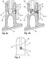
- FIGS. 2 a and 2 ba detection device for detecting discharge processes before and during a discharge process
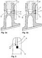
- FIG. 3two mating contact surfaces, arranged on a printed circuit board, for interacting with a membrane of the dispenser shown in FIGS. 1 to 2 b,
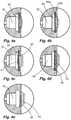
- FIGS. 4 a to 4 evarious configurations of the membrane of the dispenser shown in FIGS. 1 to 3 and
- FIGS. 5 a , 5 b and 6 afurther variant with only one mating contact surface, with respect to which the membrane is mobile.
- FIG. 1shows, in a schematic view, a dispenser 10 according to the invention.
- Said dispensertakes the form of an inhalation dispenser.
- Such dispensersare ordinarily designated as MDI or PMDI.
- the dispenser 10is provided with a housing 20 , into which a container unit 80 has been inserted.
- This container unit 80is provided with a medium reservoir 82 and also an outlet nozzle 84 which is displaceable with respect to the medium reservoir 82 and in the course of such a displacement emits a measured quantity of medium through an exit duct in the outlet nozzle 84 .
- the container unit 80has been inserted into the housing 20 from above, so that the outlet nozzle 84 projects into a bottom-side receptacle 30 .
- a discharge processcan consequently be brought about which has the result that medium is output from the medium reservoir 82 through a discharge opening 32 of the receptacle. This happens while the user is inhaling through a mouthpiece 22 of the housing 20 .
- the medium emitted through the discharge opening 32mixes with the air aspirated by the user and in this way gets into the lungs of the user as intended.
- the dispenser 10is provided with a detection device 40 and an evaluating device 90 which takes the form of an electronic counter.
- This counter 90receives a counting pulse from the detection device 40 when medium is being conveyed from the medium reservoir 82 to the discharge opening 32 .
- FIGS. 2 a and 2 bshow the detection device 40 in enlarged form.
- a connecting duct 50is provided within the receptacle 30 for the outlet nozzle 84 .
- Said connecting duct 50is provided with a branched pressure chamber 52 in which the pressure rises when medium is flowing from the outlet nozzle 84 to the discharge opening 32 in the manner represented in FIG. 2 b.
- the pressure chamber 52is bounded on one side by a membrane 60 which is deformed in the manner represented in FIG. 2 b when there is an excess pressure in the pressure chamber 52 .
- a printed circuit board 70is provided on the outside of the pressure chamber.
- two contact surfaces 72 , 74are affixed which are respectively connected to a signal line 92 , 94 .
- Said signal lines 92 , 94are, in turn, coupled with the evaluating device 90 in a manner not represented in any detail.
- the metallic contact surfaces 72 , 74are arranged to be interleaved in a comb-like manner, so that in each instance several component portions of these contact surfaces are immediately adjacent to one another. At the same time, however, the contact surfaces are galvanically isolated from one another.
- the membrane 60is designed to be electrically conductive at least on its side pointing in the direction of the contact surfaces 72 , 74 .
- the signal lines 92 , 94are connected by this means. This can be detected by the evaluating device 90 , and in response thereto a counting step can be performed.
- the updated value that provides information about the doses already emitted or still remaining in the medium reservoir 82is subsequently represented on the display 91 .
- FIGS. 4 a to 4 eshow different variants of the pressure chamber 52 and of the membrane 60 sealing off the pressure chamber. Represented by dashed lines in each instance is the shape of the membrane in the deflected state.
- a membrane 60finds application which is conductive as a whole and which has preferentially been encapsulated, by injection molding, by wall portions of the housing 20 that have been manufactured from a non-conductive plastic.
- the membrane 60 shown in FIG. 4 awhich is conductive as a whole, can be obtained by an intrinsically conductive plastic. It is also possible to make an inherently non-conductive plastic conductive by means of additives/fillers. Incorporated metallic particles, for example, enter into consideration for this.
- the membrane 60is formed in two layers.
- One layer 60 a of the membrane pointing toward the pressure chamberconsists of non-conductive plastic and serves, in particular, as an elastically deformable carrier for the outside layer 60 b which is electrically conductive, for example because it consists of conductive metal.
- the two layers 60 a , 60 bmay be layers produced in isolation which were assembled to form a composite membrane. It may also be expedient to produce such a membrane by the conducting layer 60 b being deposited on the carrier layer 60 a , for example by vapor deposition.
- a membrane 60 which is conductive as a wholeis provided, the special feature of which, however, consists in the fact that a centric region 61 of this membrane is surrounded by an annular thickening 62 .
- the centric region 61is deflected in largely undeformed manner by virtue of such a stiffening. This makes it easier to create a reliably detectable planar contact of the membrane 60 with the two contact surfaces 72 , 74 .
- the configuration shown in FIG. 4 dexhibits, in a manner similar to that shown in FIG. 4 b , a membrane having portions made of different materials.
- the conductive region of the membranehere has not been created by a membrane layer covering the entire membrane but rather by a connecting portion 63 provided only centrically on the membrane 60 , which, for example, may have been formed in the manner of a small metallic lamina.
- This metallic lamina 63may have been adhesion-bonded to an elastically deflectable portion of the membrane or, instead of this, may have been embedded in said portion. An advantageous stiffening is also achieved by this means.
- FIG. 4 eis a variant in relation to the design shown in FIG. 4 d .
- a metallic lamina 63finds application.
- the special feature in the case of the configuration according to FIG. 4 econsists in the fact that the membrane 60 is, moreover, formed in one piece with the surrounding portions of the housing 20 and consists of identical material. Only by virtue of the thin-walled nature of the membrane is the desired deflection capability achieved.
- FIGS. 5 a to 6show an alternative design.
- only one contact surface 72which is connected to signal line 92 , is provided on the printed circuit board 70 .
- the other signal line 94is permanently connected via a short connecting portion 95 to the membrane 60 which may have been formed in the same manner as shown in FIGS. 4 a to 4 e .
- the contactwhich is detected by the evaluating device 90 for the purpose of counting the discharge processes, is consequently created immediately between the membrane 60 , on the one hand, and the contact surface 72 on the other hand.
Landscapes
- Health & Medical Sciences (AREA)
- Engineering & Computer Science (AREA)
- Life Sciences & Earth Sciences (AREA)
- Anesthesiology (AREA)
- Pulmonology (AREA)
- Biomedical Technology (AREA)
- Heart & Thoracic Surgery (AREA)
- Hematology (AREA)
- Bioinformatics & Cheminformatics (AREA)
- Animal Behavior & Ethology (AREA)
- General Health & Medical Sciences (AREA)
- Public Health (AREA)
- Veterinary Medicine (AREA)
- Biophysics (AREA)
- Infusion, Injection, And Reservoir Apparatuses (AREA)
- Investigating Or Analyzing Materials By The Use Of Electric Means (AREA)
Abstract
Description
Claims (22)
Applications Claiming Priority (3)
| Application Number | Priority Date | Filing Date | Title |
|---|---|---|---|
| DE102014206350.7 | 2014-04-02 | ||
| DE102014206350.7ADE102014206350B3 (en) | 2014-04-02 | 2014-04-02 | Pharmaceutical dispenser with a detection device |
| PCT/EP2015/054981WO2015150029A1 (en) | 2014-04-02 | 2015-03-10 | Pharmaceutical dispenser with a detection device |
Publications (2)
| Publication Number | Publication Date |
|---|---|
| US20170014583A1 US20170014583A1 (en) | 2017-01-19 |
| US11052203B2true US11052203B2 (en) | 2021-07-06 |
Family
ID=52630393
Family Applications (1)
| Application Number | Title | Priority Date | Filing Date |
|---|---|---|---|
| US15/123,056Active2038-04-26US11052203B2 (en) | 2014-04-02 | 2015-03-10 | Pharmaceutical dispenser with a detection device |
Country Status (5)
| Country | Link |
|---|---|
| US (1) | US11052203B2 (en) |
| EP (1) | EP3125978B1 (en) |
| CN (1) | CN106456910B (en) |
| DE (1) | DE102014206350B3 (en) |
| WO (1) | WO2015150029A1 (en) |
Families Citing this family (10)
| Publication number | Priority date | Publication date | Assignee | Title |
|---|---|---|---|---|
| MX390900B (en) | 2016-03-24 | 2025-03-21 | Trudell Medical Int Inc | RESPIRATORY CARE SYSTEM WITH ELECTRONIC INDICATOR. |
| ES2883624T3 (en) | 2016-05-19 | 2021-12-09 | Trudell Medical Int | Smart Valve Retention Chamber |
| ES2988939T3 (en) | 2016-07-08 | 2024-11-22 | Trudell Medical Int Inc | Intelligent Oscillating Positive Expiratory Pressure Device |
| MX2019006702A (en) | 2016-12-09 | 2019-08-01 | Trudell Medical Int | Smart nebulizer. |
| FR3069762B1 (en) | 2017-08-03 | 2021-07-09 | Aptar France Sas | FLUID PRODUCT DISTRIBUTION DEVICE. |
| EP3735287B1 (en) | 2018-01-04 | 2025-03-05 | Trudell Medical International Inc. | Smart oscillating positive expiratory pressure device |
| EP3801714A4 (en) | 2018-06-04 | 2022-03-09 | Trudell Medical International | INTELLIGENT HOLDING CHAMBER WITH VALVE |
| EP3701987B1 (en) | 2019-02-28 | 2021-06-09 | Aptar Radolfzell GmbH | Pharmaceutical dispenser, in particular inhaler |
| CA3140949A1 (en) | 2019-05-17 | 2020-11-26 | Norton (Waterford) Limited | Drug delivery device with electronics |
| CA3152072A1 (en) | 2019-08-27 | 2021-03-04 | Trudell Medical International | Smart oscillating positive expiratory pressure device |
Citations (15)
| Publication number | Priority date | Publication date | Assignee | Title |
|---|---|---|---|---|
| US5505192A (en)* | 1993-11-12 | 1996-04-09 | New-Med Corporation | Dispenser monitoring system |
| US5544647A (en)* | 1994-11-29 | 1996-08-13 | Iep Group, Inc. | Metered dose inhalator |
| WO1997033640A1 (en) | 1996-03-14 | 1997-09-18 | Oneida Research Services, Inc. | Dosage counter for metered dose inhaler (mdi) systems using a miniature pressure sensor |
| US5826571A (en) | 1995-06-08 | 1998-10-27 | Innovative Devices, Llc | Device for use with metered dose inhalers (MDIS) |
| US6357442B1 (en) | 1995-06-08 | 2002-03-19 | Innovative Devices, Llc | Inhalation actuated device for use with metered dose inhalers (MDIS) |
| US20020100472A1 (en) | 1995-06-08 | 2002-08-01 | Casper Robert A. | Inhalation actuated device for use with metered dose inhalers (MDIs) |
| WO2005009325A2 (en) | 2003-07-23 | 2005-02-03 | Kos Life Sciences, Inc. | Apparatus for electronic dosage counter |
| US20070017506A1 (en)* | 2003-10-16 | 2007-01-25 | Phillip Bell | Dispensing apparatus |
| GB2470188A (en) | 2009-05-11 | 2010-11-17 | Consort Medical Plc | Dispensing apparatus dose counters |
| DE102010024912A1 (en) | 2010-06-15 | 2011-12-15 | Ing. Erich Pfeiffer Gmbh | inhalator |
| US8215299B2 (en)* | 2010-04-28 | 2012-07-10 | Synmosa Biopharma Corporation | Counter for metered dose inhaler |
| DE102013214601B3 (en) | 2013-07-25 | 2014-05-22 | Aptar Radolfzell Gmbh | Housing for container unit of inhalation device e.g. metered-dose inhaler, for oral administration of pharmaceutical medium, has membrane reversibly deformed based on pressure in pressure chamber and acting together with pushbutton |
| US8869791B2 (en)* | 2003-12-19 | 2014-10-28 | Aptar France Sas | Fluid product dispensing device |
| US20160144091A1 (en)* | 2013-06-13 | 2016-05-26 | The Nottingham Trent University | Electroactive actuators |
| US9872964B2 (en)* | 2012-08-22 | 2018-01-23 | Presspart Gmbh & Co. Kg | Metered dose inhaler counter and metered-dose inhaler including such a counter |
Family Cites Families (1)
| Publication number | Priority date | Publication date | Assignee | Title |
|---|---|---|---|---|
| ES2608458T5 (en)* | 2009-09-18 | 2022-04-04 | Altria Client Services Llc | Electronic cigarette |
- 2014
- 2014-04-02DEDE102014206350.7Apatent/DE102014206350B3/ennot_activeExpired - Fee Related
- 2015
- 2015-03-10CNCN201580017076.8Apatent/CN106456910B/enactiveActive
- 2015-03-10USUS15/123,056patent/US11052203B2/enactiveActive
- 2015-03-10WOPCT/EP2015/054981patent/WO2015150029A1/enactiveApplication Filing
- 2015-03-10EPEP15708552.3Apatent/EP3125978B1/enactiveActive
Patent Citations (22)
| Publication number | Priority date | Publication date | Assignee | Title |
|---|---|---|---|---|
| US5505192A (en)* | 1993-11-12 | 1996-04-09 | New-Med Corporation | Dispenser monitoring system |
| US5544647A (en)* | 1994-11-29 | 1996-08-13 | Iep Group, Inc. | Metered dose inhalator |
| US5826571A (en) | 1995-06-08 | 1998-10-27 | Innovative Devices, Llc | Device for use with metered dose inhalers (MDIS) |
| US6357442B1 (en) | 1995-06-08 | 2002-03-19 | Innovative Devices, Llc | Inhalation actuated device for use with metered dose inhalers (MDIS) |
| US20020100472A1 (en) | 1995-06-08 | 2002-08-01 | Casper Robert A. | Inhalation actuated device for use with metered dose inhalers (MDIs) |
| US6672304B1 (en) | 1995-06-08 | 2004-01-06 | Innovative Devices, Llc | Inhalation actuated device for use with metered dose inhalers (MDIs) |
| US6729324B2 (en) | 1995-06-08 | 2004-05-04 | Innovative Devices, Llc. | Inhalation actuated device for use with metered dose inhalers (MDIs) |
| WO1997033640A1 (en) | 1996-03-14 | 1997-09-18 | Oneida Research Services, Inc. | Dosage counter for metered dose inhaler (mdi) systems using a miniature pressure sensor |
| WO2005009325A2 (en) | 2003-07-23 | 2005-02-03 | Kos Life Sciences, Inc. | Apparatus for electronic dosage counter |
| US20050028815A1 (en)* | 2003-07-23 | 2005-02-10 | Deaton Daniel M. | Apparatus for electronic dosage counter |
| US20070017506A1 (en)* | 2003-10-16 | 2007-01-25 | Phillip Bell | Dispensing apparatus |
| US8869791B2 (en)* | 2003-12-19 | 2014-10-28 | Aptar France Sas | Fluid product dispensing device |
| GB2470188A (en) | 2009-05-11 | 2010-11-17 | Consort Medical Plc | Dispensing apparatus dose counters |
| US8215299B2 (en)* | 2010-04-28 | 2012-07-10 | Synmosa Biopharma Corporation | Counter for metered dose inhaler |
| DE102010024912A1 (en) | 2010-06-15 | 2011-12-15 | Ing. Erich Pfeiffer Gmbh | inhalator |
| US20110303221A1 (en) | 2010-06-15 | 2011-12-15 | Joerg Kohnle | Inhaler |
| EP2397178A1 (en) | 2010-06-15 | 2011-12-21 | Ing. Erich Pfeiffer GmbH | Inhalation device |
| US8746238B2 (en) | 2010-06-15 | 2014-06-10 | Aptar Radolfzell Gmbh | Inhaler |
| US9872964B2 (en)* | 2012-08-22 | 2018-01-23 | Presspart Gmbh & Co. Kg | Metered dose inhaler counter and metered-dose inhaler including such a counter |
| US20160144091A1 (en)* | 2013-06-13 | 2016-05-26 | The Nottingham Trent University | Electroactive actuators |
| DE102013214601B3 (en) | 2013-07-25 | 2014-05-22 | Aptar Radolfzell Gmbh | Housing for container unit of inhalation device e.g. metered-dose inhaler, for oral administration of pharmaceutical medium, has membrane reversibly deformed based on pressure in pressure chamber and acting together with pushbutton |
| US20160166783A1 (en) | 2013-07-25 | 2016-06-16 | Aptar Radolfzell Gmbh | Housing for an inhalation device and inhalation device for orally administering a pharmaceutical medium |
Non-Patent Citations (2)
| Title |
|---|
| International Search Report issued in Application No. PCT/EP2015/054981 with English translation dated May 28, 2015 (6 pages). |
| Written Opinion of International Searching Authority issued in Application No. PCT/EP2015/054981 dated May 28, 2015 (5 pages). |
Also Published As
| Publication number | Publication date |
|---|---|
| CN106456910B (en) | 2019-09-13 |
| EP3125978B1 (en) | 2018-01-24 |
| EP3125978A1 (en) | 2017-02-08 |
| DE102014206350B3 (en) | 2015-05-21 |
| US20170014583A1 (en) | 2017-01-19 |
| CN106456910A (en) | 2017-02-22 |
| WO2015150029A1 (en) | 2015-10-08 |
Similar Documents
| Publication | Publication Date | Title |
|---|---|---|
| US11052203B2 (en) | Pharmaceutical dispenser with a detection device | |
| CA2532868C (en) | Apparatus for electronic dosage counter | |
| US8746238B2 (en) | Inhaler | |
| US10821241B2 (en) | Housing for an inhalation device and inhalation device for orally administering a pharmaceutical medium | |
| US9648990B1 (en) | Venting system for dispenser reservoir | |
| US8281656B2 (en) | Cartridge with fill level detection | |
| CA2605571C (en) | Electronic dose counter for an inhaler | |
| EP1999441B1 (en) | Determination of cartridge content by capacitive means | |
| US8305349B2 (en) | Remote controller | |
| GB2470188A (en) | Dispensing apparatus dose counters | |
| TWI622073B (en) | Push button switch having a curved deformable contact element | |
| US11715448B2 (en) | Electronic wind instrument and method for manufacturing electronic wind instrument | |
| US8667851B2 (en) | Touch sensor mechanical interface | |
| WO2019093111A1 (en) | Input operation device | |
| US10254872B2 (en) | Operation apparatus | |
| CN111629835A (en) | Fluid product dispensing device | |
| JP2015130269A (en) | Capacitance operation device and method of manufacturing capacitance operation device | |
| US12104942B2 (en) | Deformable sleeve with sensors, measurement unit configured to be mounted on the sleeve, method storing a parameter associated with a bottle encased in the sleeve and computer program | |
| CN111653445B (en) | Injection-molded membrane switch | |
| CN208520503U (en) | A kind of diaphragm pressure sensor |
Legal Events
| Date | Code | Title | Description |
|---|---|---|---|
| AS | Assignment | Owner name:APTAR RADOLFZELL GMBH, GERMANY Free format text:ASSIGNMENT OF ASSIGNORS INTEREST;ASSIGNOR:KOERNER, JOACHIM;REEL/FRAME:039621/0337 Effective date:20160826 | |
| STPP | Information on status: patent application and granting procedure in general | Free format text:NON FINAL ACTION MAILED | |
| STPP | Information on status: patent application and granting procedure in general | Free format text:RESPONSE TO NON-FINAL OFFICE ACTION ENTERED AND FORWARDED TO EXAMINER | |
| STPP | Information on status: patent application and granting procedure in general | Free format text:FINAL REJECTION MAILED | |
| STCV | Information on status: appeal procedure | Free format text:NOTICE OF APPEAL FILED | |
| STCV | Information on status: appeal procedure | Free format text:APPEAL BRIEF (OR SUPPLEMENTAL BRIEF) ENTERED AND FORWARDED TO EXAMINER | |
| STPP | Information on status: patent application and granting procedure in general | Free format text:NON FINAL ACTION MAILED | |
| STPP | Information on status: patent application and granting procedure in general | Free format text:RESPONSE TO NON-FINAL OFFICE ACTION ENTERED AND FORWARDED TO EXAMINER | |
| STPP | Information on status: patent application and granting procedure in general | Free format text:NOTICE OF ALLOWANCE MAILED -- APPLICATION RECEIVED IN OFFICE OF PUBLICATIONS | |
| STPP | Information on status: patent application and granting procedure in general | Free format text:AWAITING TC RESP., ISSUE FEE NOT PAID | |
| STPP | Information on status: patent application and granting procedure in general | Free format text:NOTICE OF ALLOWANCE MAILED -- APPLICATION RECEIVED IN OFFICE OF PUBLICATIONS | |
| STPP | Information on status: patent application and granting procedure in general | Free format text:PUBLICATIONS -- ISSUE FEE PAYMENT RECEIVED | |
| STPP | Information on status: patent application and granting procedure in general | Free format text:PUBLICATIONS -- ISSUE FEE PAYMENT VERIFIED | |
| STCF | Information on status: patent grant | Free format text:PATENTED CASE | |
| MAFP | Maintenance fee payment | Free format text:PAYMENT OF MAINTENANCE FEE, 4TH YEAR, LARGE ENTITY (ORIGINAL EVENT CODE: M1551); ENTITY STATUS OF PATENT OWNER: LARGE ENTITY Year of fee payment:4 |