US11050336B2 - Methods of altering eddy current interactions - Google Patents
Methods of altering eddy current interactionsDownload PDFInfo
- Publication number
- US11050336B2 US11050336B2US15/532,472US201515532472AUS11050336B2US 11050336 B2US11050336 B2US 11050336B2US 201515532472 AUS201515532472 AUS 201515532472AUS 11050336 B2US11050336 B2US 11050336B2
- Authority
- US
- United States
- Prior art keywords
- magnetic
- predetermined region
- conductive member
- polarity facing
- facing magnet
- Prior art date
- Legal status (The legal status is an assumption and is not a legal conclusion. Google has not performed a legal analysis and makes no representation as to the accuracy of the status listed.)
- Active, expires
Links
Images


Classifications
- H—ELECTRICITY
- H02—GENERATION; CONVERSION OR DISTRIBUTION OF ELECTRIC POWER
- H02K—DYNAMO-ELECTRIC MACHINES
- H02K49/00—Dynamo-electric clutches; Dynamo-electric brakes
- H02K49/02—Dynamo-electric clutches; Dynamo-electric brakes of the asynchronous induction type
- H02K49/04—Dynamo-electric clutches; Dynamo-electric brakes of the asynchronous induction type of the eddy-current hysteresis type
- A—HUMAN NECESSITIES
- A62—LIFE-SAVING; FIRE-FIGHTING
- A62B—DEVICES, APPARATUS OR METHODS FOR LIFE-SAVING
- A62B1/00—Devices for lowering persons from buildings or the like
- A62B1/06—Devices for lowering persons from buildings or the like by making use of rope-lowering devices
- A62B1/08—Devices for lowering persons from buildings or the like by making use of rope-lowering devices with brake mechanisms for the winches or pulleys
- H—ELECTRICITY
- H02—GENERATION; CONVERSION OR DISTRIBUTION OF ELECTRIC POWER
- H02K—DYNAMO-ELECTRIC MACHINES
- H02K49/00—Dynamo-electric clutches; Dynamo-electric brakes
- H—ELECTRICITY
- H02—GENERATION; CONVERSION OR DISTRIBUTION OF ELECTRIC POWER
- H02K—DYNAMO-ELECTRIC MACHINES
- H02K49/00—Dynamo-electric clutches; Dynamo-electric brakes
- H02K49/02—Dynamo-electric clutches; Dynamo-electric brakes of the asynchronous induction type
- H02K49/04—Dynamo-electric clutches; Dynamo-electric brakes of the asynchronous induction type of the eddy-current hysteresis type
- H02K49/046—Dynamo-electric clutches; Dynamo-electric brakes of the asynchronous induction type of the eddy-current hysteresis type with an axial airgap
- H—ELECTRICITY
- H02—GENERATION; CONVERSION OR DISTRIBUTION OF ELECTRIC POWER
- H02K—DYNAMO-ELECTRIC MACHINES
- H02K7/00—Arrangements for handling mechanical energy structurally associated with dynamo-electric machines, e.g. structural association with mechanical driving motors or auxiliary dynamo-electric machines
- H02K7/10—Structural association with clutches, brakes, gears, pulleys or mechanical starters
- H02K7/104—Structural association with clutches, brakes, gears, pulleys or mechanical starters with eddy-current brakes
- A—HUMAN NECESSITIES
- A62—LIFE-SAVING; FIRE-FIGHTING
- A62B—DEVICES, APPARATUS OR METHODS FOR LIFE-SAVING
- A62B1/00—Devices for lowering persons from buildings or the like
- A62B1/06—Devices for lowering persons from buildings or the like by making use of rope-lowering devices
- A62B1/14—Devices for lowering persons from buildings or the like by making use of rope-lowering devices with brakes sliding on the rope
- A—HUMAN NECESSITIES
- A62—LIFE-SAVING; FIRE-FIGHTING
- A62B—DEVICES, APPARATUS OR METHODS FOR LIFE-SAVING
- A62B35/00—Safety belts or body harnesses; Similar equipment for limiting displacement of the human body, especially in case of sudden changes of motion
- A62B35/0093—Fall arrest reel devices
- F—MECHANICAL ENGINEERING; LIGHTING; HEATING; WEAPONS; BLASTING
- F16—ENGINEERING ELEMENTS AND UNITS; GENERAL MEASURES FOR PRODUCING AND MAINTAINING EFFECTIVE FUNCTIONING OF MACHINES OR INSTALLATIONS; THERMAL INSULATION IN GENERAL
- F16D—COUPLINGS FOR TRANSMITTING ROTATION; CLUTCHES; BRAKES
- F16D63/00—Brakes not otherwise provided for; Brakes combining more than one of the types of groups F16D49/00 - F16D61/00
- F16D63/002—Brakes with direct electrical or electro-magnetic actuation
Definitions
- braking mechanisms and methods of braking relative movement between membersMore specifically, braking mechanisms and related methods of use are described herein using eddy current interactions to resist relative movement between members, the magnetic flux about an eddy current region being modified beyond that for an inherent drag effect resulting from a simple magnetic pole arrangement.
- Art devicesmay utilize eddy current drag forces to impart a drag force on a conductive member undergoing relative movement with respect to a magnetic field.
- Eddy current drag effectsimpart frictionless retarding forces and hence may be useful for various braking applications, particularly where wear and tear effects are not desirable.
- Eddy current effectsare also able to be tuned to suit various applications, some examples being described in the inventor's other applications.
- eddy current drag force interactionsOne aspect of eddy current drag force interactions is that the magnetic field strength has a squared relationship on brake torque. In other words, a small increase in magnetic field strength can lead to dramatic increases in eddy current drag force.
- braking mechanisms and related methods of use using eddy current interactions to resist relative movement between membersthe magnetic flux about an eddy current region being modified beyond an inherent drag effect resulting from an unaltered magnetic field resulting from a simple magnetic pole arrangement.
- a braking mechanismcomprising:
- At least one magnetic field provided by magnetic elementscausing a magnetic flux about a predetermined region
- At least one magnetic flux density modifying meansAt least one magnetic flux density modifying means
- eddy current drag forcesare generated resisting relative movement between the at least one conductive member or a part thereof and the magnetic field.
- a braking mechanismcomprising:
- eddy current drag forcesare generated resisting relative movement between the at least one conductive member or a part thereof and the magnetic field.
- a braking mechanismcomprising:
- At least one magnetic fieldpositioned to form a Halbach array provided by magnetic elements, the Halbach array modifying the magnetic flux about a predetermined region or regions;
- eddy current drag forcesare generated resisting relative movement between the at least one conductive member or a part thereof and the magnetic field.
- a braking mechanismcomprising:
- At least one magnetic field provided by magnetic elementscausing a magnetic flux about a predetermined region
- ferro-fluidlocated at least partly about the magnetic elements and at least one conductor member or a part thereof thereby modifying the magnetic flux density of the predetermined region
- a braking mechanismcomprising:
- At least one magnetic field provided by magnetic elementscausing a magnetic flux about a predetermined region
- magnetic flux density modifying meanslocated on and/or in the at least one conductor or part thereof that increases conductivity between the magnetic elements and the at least one conductor or a part thereof thereby modifying magnetic flux density about the region;
- a method of controlling relative movement between memberscomprising the step of:
- Advantages of the above described braking mechanisms and methods of useinclude the ability to modify and tune the retarding force.
- One embodimentallows the ability to potentially cause a much larger retarding force than would be the case if no magnetic flux density increasing options were used.
- FIG. 1Aillustrates a typical magnetic field about north and south magnetic poles resulting from interaction of magnetic elements configured in a simple magnetic pole arrangement without modification of the magnetic flux density;
- FIG. 1Billustrates a magnetic field subjected to magnetic cladding
- FIG. 2illustrates an alternative example of a magnetic circuit subject to magnetic cladding
- FIG. 3illustrates an alternative braking mechanism using magnetic cladding and a conductor
- FIG. 4illustrates an alternative example of a braking mechanism using magnetic cladding and a magnetic circuit
- FIG. 5illustrates a braking mechanism using a toroid conductor passing through a Halbach array
- FIG. 6illustrates a ferro-fluid braking mechanism embodiment
- FIG. 7illustrates an alternative a ferro-fluid braking mechanism embodiment
- FIG. 8illustrates a further alternative ferro-fluid braking mechanism embodiment
- FIG. 9illustrates a modified conductor using additives in the conductor to enhance the magnetic flux
- FIG. 10illustrates a potential compact shape of braking mechanism.
- braking mechanisms and related methods of useare described herein using eddy current interactions to resist relative movement between members, the magnetic flux about an eddy current region being modified beyond an inherent drag effect resulting from an unaltered magnetic field resulting from a simple magnetic pole arrangement.
- the term ‘about’ or ‘approximately’ and grammatical variations thereofmean a quantity, level, degree, value, number, frequency, percentage, dimension, size, amount, weight or length that varies by as much as 30, 25, 20, 15, 10, 9, 8, 7, 6, 5, 4, 3, 2, or 1% to a reference quantity, level, degree, value, number, frequency, percentage, dimension, size, amount, weight or length.
- substantiallyor grammatical variations thereof refers to at least about 50%, for example 75%, 85%, 95% or 98%.
- modifyand grammatical variations thereof in the context of magnetic flux refers to either one or all of directing, intensifying, reducing, retarding, or increasing the density of magnetic flux in or about a predetermined region.
- unaltered magnetic effector ‘simple magnetic pole arrangement’ and grammatical variations thereof refers to a resistance of movement effect on an electrically conductive element, the unaltered effect being that observed for a simple (e.g. north/south) pole arrangement or arrangements without a magnetic flux modifying effect.
- One example of an altered effectmay be by using a magnetic flux redirecting or concentrating means.
- a braking mechanismcomprising:
- At least one magnetic field provided by magnetic elementscausing a magnetic flux about a predetermined region
- At least one magnetic flux density modifying meansAt least one magnetic flux density modifying means
- eddy current drag forcesare generated resisting relative movement between the at least one conductive member or a part thereof and the magnetic field.
- a braking mechanismcomprising:
- eddy current drag forcesare generated resisting relative movement between the at least one conductive member or a part thereof and the magnetic field.
- the magnetic claddingmay be formed around at least part of each magnetic element.
- the claddingmay enclose substantially all of the magnetic elements to limit and/or direct substantially all of the field generated.
- the braking mechanismmay comprise a magnetic circuit made up of at least two magnetic fields provided by magnetic elements and magnetic cladding about the magnetic elements, the cladding at least partly modifying the magnetic flux about at least two predetermined regions; and at least one conductive member or part thereof that interacts with the predetermined regions.
- the magnetic circuitmay be formed by using two opposing sets of magnetic elements and cladding, a gap being located about the predetermined region and the at least one conductive member or a part thereof pass through the region(s).
- the two predetermined regions in a circuitmay be located opposite each other. This alignment may be useful for conductor shape and design but not essential.
- the conductive membermay be rotor shaped.
- the conductive membermay be rod shaped.
- the term rodrefers to an elongated solid that may be curvilinear shaped but could also have polygonal cross-section.
- the rodmay be solid or hollow.
- the magnetic fieldmay comprise one north polarity facing magnet element and one south polarity facing magnet element aligned so as to form a magnetic field between the elements.
- the predetermined regionmay be located about an area of maximum magnetic flux density.
- the predetermined regionmay be located immediately between the magnetic elements. This is typically the space immediately between the magnetic poles but may be at other points such as that which may be generated from a Halbach array noted in more detail below.
- the predetermined regionmay have a gap through which the conductive member or members may pass.
- a braking mechanismcomprising:
- At least one magnetic fieldpositioned to form a Halbach array provided by magnetic elements, the Halbach array modifying the magnetic flux about a predetermined region or regions;
- eddy current drag forcesare generated resisting relative movement of the at least one conductive member or a part thereof and the magnetic field.
- the Halbach arraymay comprise a magnetic array arranged in a semi-circle shape, the predetermined region being of the highest magnetic flux density within the circular region.
- the at least one conductormay have various shapes, examples being circular, spherical, ovoid and toroid shaped.
- the at least one conductor or a part thereofmay pass through the center of the Halbach array.
- the at least one conductor member or a part thereofmay be solid or segmented. If the conductor is segmented, each segment may for example move about the toroid axis in conjunction with driving conductor movement about a primary axis thereby generating even greater eddy current drag force from both conductor and segment movement.
- a braking mechanismcomprising:
- At least one magnetic field provided by magnetic elementscausing a magnetic flux about a predetermined region
- ferro-fluidlocated at least partly about the magnetic elements and at least one conductor member or a part thereof thereby modifying the magnetic flux density of the predetermined region
- a gapmay exist between the magnetic elements that the at least one conductor member or a part thereof passes through.
- Backing platesmay be used behind the magnetic elements to seal the magnetic elements and the at least one conductor or a part thereof within a backing plate cavity.
- the free space within the backing plate cavitymay be filled with ferro-fluid.
- Sealingrefers to the magnetic elements and the at least one conductor being enclosed within other elements to form a sealed region.
- the sealmay be impermeable preventing loss of materials, e.g. ferro fluid, out of the sealed region.
- the magnetic elementsmay be spaced apart by use of separators or barriers. These barriers may also reduce the cavity size in which ferro-fluid is placed. The barriers may also prevent ‘short circuiting’ of the magnetic fields outside of the region of the conductor.
- the braking mechanismmay comprise backing plates as above with magnetic elements therein.
- Two conductor platesmay be located between the magnetic elements defining a cavity or space between the conductor plates.
- the cavity or space between the conductorsmay be filled with a ferro-fluid.
- the ferro-fluidmay also have fluid properties that inhibit conductor movement thereby further enhancing a drag effect.
- Fluid propertiesmay refer to the fluid viscosity—viscous drag being a known means to absorb kinetic or motive energy.
- fluid propertiessuch as conductivity and viscosity may be varied to alter the drag force dynamics.
- a braking mechanismcomprising:
- At least one magnetic field provided by magnetic elementscausing a magnetic flux about a predetermined region
- magnetic flux density modifying meanslocated on and/or in the at least one conductor or part thereof that increases magnetic ‘conductivity’ between the magnetic elements and the at least one conductor or a part thereof thereby modifying magnetic flux density about the region;
- the at least one conductor or a part thereofmay modify the magnetic flux through use of additives such as particles or nano-particles located on or in part of or all of the conductor(s).
- the particlesmay be manufactured from various magnetic flux enhancing materials including for example iron and nickel.
- the particlesmay be formed into the conductors, bonded to the conductor exterior and/or laminated to the conductor exterior.
- the various braking mechanisms described abovemay take a wide range of final topologies including linear motion, rotary motion, polar motion, axial motion and so forth. These ranges of topology can be combined to achieve various types of relative movement between the magnetic field(s) and the conductor(s).
- the conductor shapeitself may also be varied for example to optimize the space and overall braking mechanism size and shape.
- the conductormay have fins and the fins may act as conductor parts that pass through the regions in this embodiment, the fins may extend from a central hub in different directions thereby optimizing the conductive surface passing through multiple magnetic flux regions.
- a method of controlling relative movement between memberscomprising the step of:
- the magnetic field sectionsmay for example be linked to a first member of a braking mechanism and the conductor member or members linked to a second member.
- an autobelay or self-retracting lifeline (SRL) embodimentmay use the braking mechanisms.
- the conductormay for example be linked to a line on a spool and the magnetic field sections may be linked to a separate rotor and, when the line extends at a predetermined rate, potentially equating to a fall, the conductor and magnetic elements interact to brake pay out of the line and prevent an accident by braking the fall.
- SRLself-retracting lifeline
- Advantages of the above described braking mechanisms and methods of useinclude the ability to modify and tune the braking force and potentially cause a much larger braking force than would be the case if no magnetic flux density increasing options were used.
- magnetic cladding embodimentsare described as a means to modify the magnetic flux by directing and increasing the flux density about a region.
- FIG. 1Aillustrates, an unclad magnetic field.
- the magnetic field 3includes two magnetic elements (a north 1 and south 2 pole) and the magnetic field 3 generated follows a classic field path about the poles 1 , 2 , the strongest flux region 4 being directly between the elements 1 , 2 .
- FIG. 1Billustrates how the field 3 changes when magnetic cladding 6 is used.
- the cladding 6 showndirects and increases the magnetic flux density about a predetermined region, in the example being the space 7 immediately between the magnetic elements 1 , 2 .
- FIG. 2illustrates a magnetic circuit 10 .
- the circuit 10is established with magnet elements 13 , 14 establishing a pole pair.
- the magnet elements 13 , 14are linked together with a structural material 15 that is of high magnetic permeability, forming a magnetic circuit.
- Claddingis established with magnets 12 adjacent to the field magnets 13 , 14 .
- Further cladding 16is provided adjacent to the gap region 18 .
- the magnetic field of cladding magnets 12 , 16focus and intensify a resulting magnetic field in the gap region 18 .
- FIGS. 3 and 4illustrate potential braking mechanisms utilizing the cladded magnetic fields of FIGS. 1 and 2 in conjunction with a conductor member 20 that passes through the region(s) 21 .
- the conductor 20has an elongated foot ending that passes through the region 21 .
- FIG. 4illustrates a conductor 20 moving through the magnetic circuit 10 of FIG. 2 , in this case with two sections 20 A, 20 B of the conductor member 20 interacting with the different magnetic regions 21 A, 21 B and thereby increasing the potential eddy current drag forces.
- movement of the conductor member relative to the magnetic field(s)may be linear, rotational or in various directions and the examples shown should not be seen as limiting.
- the conductor shapemay also take various forms including rod shapes or rotor shapes for example.
- the important aspectis different relative movement between the magnetic elements and conductor member or members.
- the magnetic elementsmay be stationary and the conductor member(s) move.
- the conductor member(s)may remain stationary and the magnetic elements may move.
- both the magnetic elements and conductor member(s)may move but with different velocities and potentially also different movement directions.
- Halbach arraysmay also be used as a means to direct and increase the density of the magnetic flux about a predetermined region.
- FIG. 5shows an example of a potential braking mechanism utilizing a Halbach array.
- the magnetic array 30is arranged in a semi-circular shape and the Halbach array intensifies the magnetic flux in the predetermined region 31 within the circular region.
- a conductor 32passes through the semi-circular region 31 generating eddy current drag forces as this occurs.
- the conductor member 32has a toroid shape however, various shapes could be used.
- FIGS. 6 to 8illustrate alternative embodiments utilizing a ferro-fluid to modify the magnetic flux density by increasing the magnetic permeability between the magnetic elements and conductor.
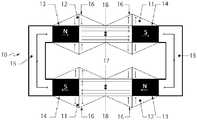
- FIG. 6illustrates an embodiment where the braking mechanism 40 comprises two backing plates 41 , 42 , magnetic elements 43 , 44 extending orthogonally from the backing plates 41 , 42 and a gap between the magnetic elements 43 , 44 that a conductor or conductors 45 pass through.
- the backing plates 41 , 42seal the magnetic elements 43 , 44 and conductor 45 within a cavity.
- the free space within the cavitymay then be filled with the ferro-fluid 46 noted above.
- FIG. 7shows an alternative embodiment 40 A, where the magnetic elements 43 , 44 are spaced apart by use of separators or barriers 47 and these barriers also reduce the cavity size in which ferro-fluid 46 is placed.
- the barriers 47may prevent short circuiting of the magnetic fields and may reduce the amount of ferro-fluid 46 required.
- the barriers 47may extend past the extent of the magnetic element 43 , 44 to further reduce the cavity size and short circuiting of the magnetic fields.
- FIG. 8shows a further embodiment 40 B, the braking mechanism comprising backing plates 41 , 42 as above with magnetic elements 43 , 44 therein.
- Two conductor plates 45 A, 45 Bmay be located between the magnetic elements 43 , 44 defining a cavity or space between the conductor plates 45 A, 45 B.
- the cavity or space between the conductor plates 45 A, 45 Bmay be filled with a ferro-fluid 46 .
- the ferro-fluid 46may also have fluid properties such as a viscous drag that inhibit conductor 45 , 45 A, 45 B movement thereby further enhancing a drag effect.
- FIG. 9illustrates a further braking mechanism 50 , the mechanism 50 comprising the same backing plates 51 , 52 and magnetic elements 53 , 54 as FIGS. 6 to 8 , however, instead of a ferro-fluid, the magnetic flux direction and density is modified by the use of magnetic flux modifying materials in the form of particles or additives 55 mixed in or placed on the conductor member 56 .
- the additives/particles 55may be located on or in the conductor member(s) 56 .
- the particles 55may be manufactured from various magnetic flux enhancing materials including for example iron and nickel.
- the particles 55may be formed into the conductor member(s) 56 , bonded to the conductor member 56 exterior and/or laminated to the conductor member 56 exterior. In FIG. 9 , the particles 55 are spread evenly throughout the conductor member 56 structure.
- the conductor member and magnetic fieldmay take various shapes and forms.
- Some braking mechanismsmay require compact forms or topologies.
- One way of achieving a compact formmay be to use a conductor 60 with fins 61 , the fins 61 acting as conductor 60 parts that pass through the flux regions 62 as shown in FIG. 10 .
- the fins 61extend from a central hub 63 in different directions thereby optimizing the conductive surface passing through multiple magnetic flux regions 62 .
Landscapes
- Engineering & Computer Science (AREA)
- Power Engineering (AREA)
- General Engineering & Computer Science (AREA)
- Mechanical Engineering (AREA)
- Health & Medical Sciences (AREA)
- General Health & Medical Sciences (AREA)
- Business, Economics & Management (AREA)
- Emergency Management (AREA)
- Dynamo-Electric Clutches, Dynamo-Electric Brakes (AREA)
- Soft Magnetic Materials (AREA)
- Braking Arrangements (AREA)
Abstract
Description
- a rotor in a rotary turbine;
- exercise equipment e.g. rowing machines, epicyclic trainers;
- roller-coasters and other amusement rides;
- Elevator and escalator systems;
- evacuation descenders and fire escape devices;
- conveyer systems:
- rotary drives in factory production facilities;
- materials handling devices such as conveyer belts or a braking device in a chute;
- dynamic display signage to control the rate of change of rotating signs;
- roadside safety systems e.g. the eddy current brake may be connected in a system to provide crash attenuation though the dissipation of energy via the brake;
- seat belts in vehicles;
- zip lines;
- braking mechanisms for trolleys and carriages.
Claims (7)
Applications Claiming Priority (3)
| Application Number | Priority Date | Filing Date | Title |
|---|---|---|---|
| NZ70154814 | 2014-12-04 | ||
| NZ701548 | 2014-12-04 | ||
| PCT/NZ2015/050206WO2016089226A1 (en) | 2014-12-04 | 2015-12-04 | Methods of altering eddy current interactions |
Related Parent Applications (1)
| Application Number | Title | Priority Date | Filing Date |
|---|---|---|---|
| PCT/NZ2015/050206A-371-Of-InternationalWO2016089226A1 (en) | 2014-12-04 | 2015-12-04 | Methods of altering eddy current interactions |
Related Child Applications (1)
| Application Number | Title | Priority Date | Filing Date |
|---|---|---|---|
| US17/332,736ContinuationUS11777391B2 (en) | 2014-12-04 | 2021-05-27 | Methods of altering eddy current interactions |
Publications (2)
| Publication Number | Publication Date |
|---|---|
| US20180269767A1 US20180269767A1 (en) | 2018-09-20 |
| US11050336B2true US11050336B2 (en) | 2021-06-29 |
Family
ID=56092064
Family Applications (2)
| Application Number | Title | Priority Date | Filing Date |
|---|---|---|---|
| US15/532,472Active2036-12-06US11050336B2 (en) | 2014-12-04 | 2015-12-04 | Methods of altering eddy current interactions |
| US17/332,736ActiveUS11777391B2 (en) | 2014-12-04 | 2021-05-27 | Methods of altering eddy current interactions |
Family Applications After (1)
| Application Number | Title | Priority Date | Filing Date |
|---|---|---|---|
| US17/332,736ActiveUS11777391B2 (en) | 2014-12-04 | 2021-05-27 | Methods of altering eddy current interactions |
Country Status (4)
| Country | Link |
|---|---|
| US (2) | US11050336B2 (en) |
| EP (2) | EP3912685A1 (en) |
| CN (2) | CN106999736B (en) |
| WO (1) | WO2016089226A1 (en) |
Cited By (1)
| Publication number | Priority date | Publication date | Assignee | Title |
|---|---|---|---|---|
| US12214995B2 (en) | 2021-11-05 | 2025-02-04 | Otis Elevator Company | Safety brake system |
Families Citing this family (18)
| Publication number | Priority date | Publication date | Assignee | Title |
|---|---|---|---|---|
| BR112017003080B1 (en) | 2014-08-18 | 2022-10-25 | Eddy Current Limited Partnership | LOCKING DEVICES |
| AU2015304095B2 (en) | 2014-08-18 | 2020-05-07 | Eddy Current Limited Partnership | Tuning of a kinematic relationship between members |
| CN110932523B (en) | 2014-08-18 | 2022-09-06 | 涡流有限合伙公司 | Adjustment of kinematic relationships between components |
| BR112017010687A2 (en) | 2014-12-04 | 2017-12-26 | Eddy Current Lp | transmissions incorporating eddy current braking |
| CA2969423C (en) | 2014-12-04 | 2024-01-02 | Eddy Current Limited Partnership | Energy absorbing apparatus |
| AU2015355674A1 (en) | 2014-12-04 | 2017-06-08 | Eddy Current Limited Partnership | Eddy current brake configurations |
| BR112017010692B1 (en) | 2014-12-04 | 2022-03-03 | Eddy Current Limited Partnership | Activation coupling between elements |
| MX384701B (en) | 2015-12-18 | 2025-03-14 | Eddy Current Lp | A VARIABLE BEHAVIOR CONTROL MECHANISM FOR A MOTOR SYSTEM. |
| CN109316670B (en)* | 2018-10-30 | 2020-09-29 | 重庆理工大学 | Permanent magnet variable magnetic field variable area magnetorheological fluid safe landing device |
| EP3654049A1 (en)* | 2018-11-15 | 2020-05-20 | Koninklijke Philips N.V. | Eddy current brake for patient table of mri |
| US11732769B2 (en) | 2019-01-09 | 2023-08-22 | Green Wave Power Systems Llc | Magnetically-coupled torque-assist apparatus |
| WO2020144668A1 (en) | 2019-01-09 | 2020-07-16 | Green Wave Power Systems Llc | System and method for perturbing a permanent magnet asymmetric field to move a body |
| WO2020146594A1 (en)* | 2019-01-09 | 2020-07-16 | Green Wave Power Systems Llc | Magnetically-coupled torque-assist apparatus |
| CN110195755B (en)* | 2019-05-16 | 2020-10-20 | 南京理工大学 | Variable damping permanent magnet eddy current damper |
| US11831206B2 (en)* | 2020-03-27 | 2023-11-28 | Ohio State Innovation Foundation | Axial-end Halbach array cladding magnet magnetically-geared machine |
| US11646630B2 (en) | 2021-09-30 | 2023-05-09 | Green Wave Power Systems Llc | System and method for generating rotation of a body to generate energy and reduce climate change |
| CN115346337B (en) | 2022-08-23 | 2023-07-21 | 云南电网有限责任公司电力科学研究院 | Method, controller, safety belt and storage medium for preventing workers from falling |
| CN116899138A (en)* | 2023-08-08 | 2023-10-20 | 广东工业大学 | Anti-falling protection device for electric power pole tower |
Citations (216)
| Publication number | Priority date | Publication date | Assignee | Title |
|---|---|---|---|---|
| US2058024A (en) | 1934-12-11 | 1936-10-20 | Westinghouse Air Brake Co | Eddy current brake |
| US2122315A (en) | 1936-06-11 | 1938-06-28 | Fosty Leopold | Fire escape |
| US2122312A (en) | 1937-05-25 | 1938-06-28 | Cassion John | Door attachment |
| US2272509A (en) | 1941-06-11 | 1942-02-10 | Cavallo Friedrich | Variable speed friction gear power transmission device |
| US2409009A (en) | 1945-07-24 | 1946-10-08 | Gen Electric | One-way drive with magnetic lock |
| US2428104A (en) | 1944-06-14 | 1947-09-30 | Martin P Winther | Eddy-current apparatus |
| US2437871A (en) | 1943-02-09 | 1948-03-16 | Alfred R Wood | Magnetic coupling |
| US2492776A (en) | 1948-08-11 | 1949-12-27 | Martin P Winther | Dynamoelectric machine |
| GB721748A (en) | 1950-06-22 | 1955-01-12 | Baermann Max | Improvements in or relating to permanent magnet brakes or clutches |
| US2771171A (en) | 1955-07-06 | 1956-11-20 | Lab Equipment Corp | Magnetically activated torque coupling |
| US2807734A (en) | 1954-11-22 | 1957-09-24 | Control Instr Company | Torque transmitting device |
| GB908128A (en) | 1958-06-10 | 1962-10-17 | Andre Duban | Improvements in or relating to ratchet-and-pawl devices |
| US3364795A (en) | 1964-03-27 | 1968-01-23 | Renault | Eddy current-type devices for automatically controlling gear changes on vehicles |
| US3447006A (en) | 1967-09-28 | 1969-05-27 | Bliss Co | Electrodynamic brake of magnetic fluid type |
| US3721394A (en) | 1970-07-03 | 1973-03-20 | Kabel Metallwerke Ghh | Apparatus for uncoiling wire from a spool |
| JPS4997163A (en) | 1973-01-25 | 1974-09-13 | ||
| US3868005A (en) | 1973-03-14 | 1975-02-25 | Gen Electric | Friction clutch with centrifugal and magnetic speed control |
| US3934446A (en) | 1974-04-16 | 1976-01-27 | Betzalel Avitzur | Methods of and apparatus for production of wire |
| US3962595A (en) | 1974-12-20 | 1976-06-08 | W. J. Industries, Incorporated | Magnetic particle brake |
| US3967794A (en) | 1974-01-21 | 1976-07-06 | Foehl Artur | Device for initiating the blocking of a reel shaft for a safety belt winding-up automat |
| US4078719A (en) | 1976-04-29 | 1978-03-14 | Beckman Instruments, Inc. | Eddy current brake for air driven centrifuge |
| US4093186A (en) | 1976-11-22 | 1978-06-06 | Golden Steven T | Line brake device useful for fire escape |
| JPS53113528U (en) | 1977-02-18 | 1978-09-09 | ||
| US4224545A (en) | 1977-08-27 | 1980-09-23 | Ferranti Limited | Speed control |
| US4271944A (en) | 1979-02-12 | 1981-06-09 | Hanson Douglas R | Single revolution torque limiting clutch |
| JPS56107092A (en) | 1979-12-12 | 1981-08-25 | Pirelli | Twisting machine |
| US4306688A (en) | 1979-02-22 | 1981-12-22 | Injecto Mold, Inc. | Hose reel assembly |
| JPS5825152U (en) | 1981-08-11 | 1983-02-17 | トヨタ自動車株式会社 | Seat belt energy absorption device |
| US4416430A (en) | 1982-02-01 | 1983-11-22 | Draft Systems, Inc. | Load lowering device |
| US4434971A (en) | 1981-02-11 | 1984-03-06 | Armco Inc. | Drilling rig drawworks hook load overspeed preventing system |
| US4544111A (en)* | 1982-03-09 | 1985-10-01 | Shimano Industrial Company Limited | Brake for a fishing reel |
| JPS60259278A (en) | 1984-06-04 | 1985-12-21 | 神鋼電機株式会社 | Falling apparatus using eddy current type brake |
| US4561605A (en) | 1981-12-25 | 1985-12-31 | Shimano Industrial Company Limited | Brake for a fishing reel |
| US4567963A (en) | 1983-05-26 | 1986-02-04 | Kabushiki Kaisha Miyano Seisakusho | Eddy current retarder for use in emergency escape as from higher stories of a building |
| US4612469A (en) | 1983-11-10 | 1986-09-16 | Kabushiki Kaisha Sankyo Seiki Seisakusho | Speed governor |
| US4690066A (en) | 1984-06-30 | 1987-09-01 | Kabushiki Kaisha Toshiba | Electromagnetically floated carrier system with stopping unit |
| EP0247818A2 (en) | 1986-05-28 | 1987-12-02 | Barrow Hepburn Equipment Ltd | Fall-arrest apparatus |
| JPS6364542A (en) | 1986-09-03 | 1988-03-23 | Sankyo Seiki Mfg Co Ltd | Fan motor |
| US4938435A (en) | 1988-12-30 | 1990-07-03 | Frost Engineering Development Corporation | Personnel lowering device |
| US4957644A (en) | 1986-05-13 | 1990-09-18 | Price John T | Magnetically controllable couplings containing ferrofluids |
| US4974706A (en)* | 1986-02-26 | 1990-12-04 | Shinko Electric Co., Ltd. | Torque limiter |
| US5054587A (en) | 1987-04-30 | 1991-10-08 | Tokyo-Buhin Kogyo Co., Ltd. | Eddy-current brake |
| US5064029A (en) | 1988-10-31 | 1991-11-12 | Sumitomo Metal Industries, Ltd. | Eddy current retarder |
| EP0460494A1 (en) | 1990-06-07 | 1991-12-11 | HARTING ELEKTRONIK GmbH | Electromagnetic actuating device for a belt retractor locking mechanism |
| US5084640A (en) | 1987-03-02 | 1992-01-28 | Unisys Corporation | Eddy current brake with N impedence gaps |
| DE9300966U1 (en) | 1993-01-25 | 1993-03-11 | Chen, Jeff, Shyong City | Torque control device |
| US5205386A (en) | 1992-03-05 | 1993-04-27 | United Technologies Corporation | Pawl and ratchet clutch with pawl holdback |
| US5248133A (en) | 1991-04-01 | 1993-09-28 | National Aerospace Laboratory Of Science & Technology Agency | Multidimensional damping apparatus |
| JPH05296287A (en) | 1992-04-22 | 1993-11-09 | Fuji Elelctrochem Co Ltd | Magnetic damper |
| JPH0584347U (en) | 1992-04-21 | 1993-11-16 | 大成建設株式会社 | Lifeline retractable safety equipment |
| US5272938A (en) | 1992-12-04 | 1993-12-28 | Hsu Chi Hsueh | Flat rim type motor drive mechanism for bicycles |
| US5342000A (en) | 1990-02-02 | 1994-08-30 | Barmag Ag | Strand braking apparatus |
| US5392881A (en) | 1993-10-06 | 1995-02-28 | The United States Of America As Represented By The Secretary Of The Navy | Device for dampening vibratory motion |
| WO1995016496A1 (en) | 1993-12-14 | 1995-06-22 | Strickler James H | Sport climbing safety device |
| US5441137A (en) | 1994-05-04 | 1995-08-15 | Eaton Corporation | Clutch with a centrifugally applied ball ramp actuator |
| US5465815A (en) | 1994-01-10 | 1995-11-14 | Ikegami; Iwao | Magnetic brake |
| US5477093A (en) | 1993-05-21 | 1995-12-19 | Magna Force, Inc. | Permanent magnet coupling and transmission |
| US5483849A (en) | 1992-02-24 | 1996-01-16 | Sankyo Seiki Mfg. Co., Ltd. | Governor with pulley |
| US5495131A (en) | 1993-05-28 | 1996-02-27 | Satcon Technology Corp. | Parallel air gap serial flux A.C. electrical machine |
| WO1996017149A1 (en) | 1994-12-02 | 1996-06-06 | Itt Automotive Electrical Systems, Inc. | Centrifugal clutch for power door locks |
| JPH08252025A (en) | 1995-03-15 | 1996-10-01 | Atex Co Ltd | Bale diameter variable type roll baler |
| US5636804A (en) | 1993-10-05 | 1997-06-10 | Bando Leports, Ltd. | Double-bearing fishing reel |
| US5692693A (en) | 1994-04-01 | 1997-12-02 | Daiwa Seiko, Inc. | Backflash preventive device for preventing over rotation of a spool for a fishing reel |
| US5711404A (en) | 1997-02-05 | 1998-01-27 | Lee; Ying-Che | Magnetic adjustable loading device with eddy current |
| US5712520A (en) | 1993-05-21 | 1998-01-27 | Magna Force, Inc. | Permanent magnet braking system |
| US5722612A (en) | 1994-01-18 | 1998-03-03 | Barrow Hepburn Sala Ltd. | Clutch mechanism for use in safety apparatus |
| JPH1098868A (en) | 1996-09-24 | 1998-04-14 | Aichi Steel Works Ltd | Pole layout system for electromagnetic brake |
| US5742986A (en) | 1997-02-13 | 1998-04-28 | Trw Inc. | Seat belt buckle with hall effect locking indicator and method of use |
| JPH10140536A (en) | 1996-11-12 | 1998-05-26 | Taisei Corp | Underwater mat installation base and underwater mat installation method |
| JPH10178717A (en) | 1996-10-15 | 1998-06-30 | Polymer Giya Kk | Safety device for work at high place |
| US5779178A (en) | 1996-11-07 | 1998-07-14 | Rostra Precision Controls, Inc. | Seat belt retractor assembly having magnetically actuated locking mechanism |
| US5791584A (en) | 1996-01-25 | 1998-08-11 | Kuroiwa; Sachimasa | Tension control unit for filamentous material |
| US5822874A (en) | 1996-04-29 | 1998-10-20 | Nemes; Anne | Automatically retracting chalk line marking tool |
| WO1998047215A1 (en) | 1997-04-14 | 1998-10-22 | Zornes David A | Magnet coupler having enhanced electromagnetic torque |
| JPH10304799A (en) | 1997-03-06 | 1998-11-17 | Ryobi Ltd | Centrifugal braking device for double bearing reel |
| US5862891A (en) | 1994-10-28 | 1999-01-26 | Knorr-Bremse Systeme Fur Scheinenfahrzeuge Gmbh | Electromagnetic or permanent-magnetic rail brake |
| EP0909684A2 (en) | 1997-10-14 | 1999-04-21 | Breed Automotive Technology, Inc. | Energy absorbing belt anchors for safety belts in vehicles |
| JPH11119680A (en) | 1997-10-20 | 1999-04-30 | Ricoh Co Ltd | Liquid crystal display |
| JPH11189701A (en) | 1997-10-20 | 1999-07-13 | Toagosei Co Ltd | Curable composition |
| US5928300A (en) | 1997-10-30 | 1999-07-27 | Simula Inc. | Three-axis aircraft crash sensing system |
| JPH11315662A (en) | 1998-05-06 | 1999-11-16 | Miwa Lock Co Ltd | Closer for sliding door |
| GB2340461A (en) | 1998-08-17 | 2000-02-23 | Honda Motor Co Ltd | Automotive vehicle body structure which reduces deceleration effects on occupants during a crash |
| US6042517A (en) | 1998-09-10 | 2000-03-28 | Bell Sports, Inc. | Bicycle trainer magnetic resistance device |
| US6041897A (en) | 1996-05-10 | 2000-03-28 | Knorr-Bremse System Fur Schienenfahrzeuge Gmbh | Magnetic brake linear eddy current brake |
| US6051897A (en) | 1999-05-05 | 2000-04-18 | Synchro-Start Products, Inc. | Solenoid actuator with positional feedback |
| US6062350A (en) | 1995-04-13 | 2000-05-16 | Alfons Saiko | Braking system for an amusement device |
| US6086005A (en) | 1997-03-11 | 2000-07-11 | Daiwa Seiko, Inc. | Fishing reel with magnetic force spool rotational-speed control during spool free rotational state |
| JP2000189530A (en) | 1998-12-25 | 2000-07-11 | Ito Seisakusho:Kk | Fall preventing device for eminence work |
| JP2000316272A (en) | 1999-04-27 | 2000-11-14 | Topre Corp | Maximum bicycle speed limiter |
| JP2001017041A (en) | 1999-07-02 | 2001-01-23 | Akebono Brake Ind Co Ltd | Braking mechanism for reel supported with bearings at both ends |
| JP2001028876A (en)* | 1999-07-12 | 2001-01-30 | Isuzu Motors Ltd | Eddy-current speed reducer |
| GB2352645A (en) | 1999-07-21 | 2001-02-07 | Chen Yu Peng | Magnetic resistance device for exercise machine |
| GB2352644A (en) | 1999-07-21 | 2001-02-07 | Chen Yu Peng | Magnetic resistance device for exercise machine |
| GB2352784A (en) | 1999-08-04 | 2001-02-07 | Moog Inc | Energy-absorbing brake |
| US6209688B1 (en)* | 1998-09-30 | 2001-04-03 | Isuzu Motors Limited | Eddy current reduction apparatus |
| US6220403B1 (en) | 1998-04-02 | 2001-04-24 | Isuzu Motors Limited | Eddy current braking system |
| EP1094240A2 (en) | 1999-10-21 | 2001-04-25 | Simula, Inc. | Energy absorbing shear strip bender |
| WO2001038123A1 (en) | 1999-11-22 | 2001-05-31 | Pribonic Edward M | Apparatus including eddy current braking system |
| GB2357563A (en) | 1999-12-21 | 2001-06-27 | Latchways Plc | An energy absorber/ fall arrester |
| US6279682B1 (en) | 1994-01-13 | 2001-08-28 | Sala Group Limited | Speed responsive coupling device especially for fall arrest apparatus |
| US6412611B1 (en) | 2000-07-17 | 2002-07-02 | Magnetar Technologies, Ltd | Eddy current brake system with dual use conductor fin |
| US6460828B1 (en) | 1999-04-01 | 2002-10-08 | Demag Cranes & Components Gmbh | Brake, in particular for a drive of a hoist |
| US6466119B1 (en)* | 1996-09-06 | 2002-10-15 | Chester Drew | Magnetic circuit |
| US20020162477A1 (en) | 2001-03-02 | 2002-11-07 | Emiliano Palumbo | Dual cable zipline having mechanical ascension and braking systems |
| US20020179372A1 (en) | 2000-07-06 | 2002-12-05 | Schreiber Phillip H. | Controlled descent device |
| US6523650B1 (en)* | 2000-02-15 | 2003-02-25 | Magnetar Technologies, Inc. | Permanent magnet eddy brake with flux-steering poles |
| US6557673B1 (en) | 2001-12-21 | 2003-05-06 | Visteon Global Technologies, Inc. | Integral park brake/eddy current brake assembly |
| US6561451B1 (en) | 1998-12-22 | 2003-05-13 | Asm Automation Sensorik Messtechnik Gmbh | Measuring cable travel sensor with longitudinal drive for the cable drum |
| US20030116391A1 (en) | 2001-12-21 | 2003-06-26 | Desta Girma Gete | Eddy current brake system |
| WO2003055560A1 (en) | 2001-12-28 | 2003-07-10 | Suter Racing International Ag | Abseiling device used as rescue equipment in disaster situations, particularly fires in buildings or tall buildings |
| US20030168911A1 (en) | 2002-03-07 | 2003-09-11 | Sohel Anwar | Closed-loop control algorithm for an eddy current braking system |
| US20030211914A1 (en) | 2002-05-09 | 2003-11-13 | Perkins William Paul | Differential assembly |
| EP1401087A1 (en) | 2002-09-20 | 2004-03-24 | Tai-Her Yang | Axially movable rotor |
| US20040055836A1 (en) | 1999-11-22 | 2004-03-25 | Pribonic Edward M. | Eddy current braking apparatus with adjustable braking force |
| US20040073346A1 (en) | 2001-10-05 | 2004-04-15 | Michael Roelleke | Method for determining a decision for the triggering of restraint means in a vehicle |
| EP1432101A1 (en) | 2002-12-20 | 2004-06-23 | Tai-Her Yang | Electrical machine with structure for axially moving the rotor using centrifugal force |
| US6756870B2 (en) | 2000-09-18 | 2004-06-29 | Isuzu Motors Limited | Composite magnet of electromagnet and permanent magnet, and eddy current retarder |
| US20040168855A1 (en) | 2003-02-21 | 2004-09-02 | Leon Robert L. | Apparatus for exterior evacuation from buildings |
| US6793203B2 (en) | 2000-02-28 | 2004-09-21 | Wirth Maschinen- Und Bohrgerätefabrik GmbH | Hoisting gear |
| US20040191401A1 (en) | 2003-02-19 | 2004-09-30 | Bytnar Stephen C. | Methods and compositions for dust and erosion control |
| EP1480320A1 (en) | 2002-02-28 | 2004-11-24 | SUMITOMO METAL INDUSTRIES, Ltd. | Eddy current speed reducer |
| US20050051659A1 (en) | 2003-09-05 | 2005-03-10 | D B Industries, Inc. | Self-retracting lifeline |
| US20050082410A1 (en) | 2003-10-15 | 2005-04-21 | Takata Corporation | Seatbelt retractor and seatbelt device |
| US20050117258A1 (en) | 2003-03-28 | 2005-06-02 | Hitachi Global Storage Technologies Netherlands, B.V. | Rotary disk storage device and method for releasing actuator suspension assembly |
| US6918469B1 (en) | 2000-02-15 | 2005-07-19 | Magnetar Technologies, Inc. | Curvilinear eddy current braking apparatus |
| EP1564868A1 (en) | 2004-02-16 | 2005-08-17 | Minebea Co., Ltd. | Electric machine |
| US20050189830A1 (en) | 2004-03-01 | 2005-09-01 | Corbin Philip Iii | Apparatus for transferring torque magnetically |
| US20050263356A1 (en) | 2004-05-28 | 2005-12-01 | Marzano Domenic P | Selectively incrementally actuated linear eddy current braking system |
| US6973999B2 (en) | 2003-01-06 | 2005-12-13 | Shimano Inc. | Braking device for a dual bearing reel |
| JP2005353123A (en) | 2004-06-08 | 2005-12-22 | Nidec Pigeon Corp | Clamper for disk player |
| US7011607B2 (en) | 2002-01-23 | 2006-03-14 | Saris Cycling Group, Inc. | Variable magnetic resistance unit for an exercise device |
| US7014026B2 (en) | 2001-06-07 | 2006-03-21 | Drussel Wilfley Design, L.L.C. | Manual/automatic pressure control mechanism for centrifugal clutch |
| US7018324B1 (en) | 2004-11-30 | 2006-03-28 | Lily Lin | Magnetic controlled loading device in combination of a power generating set and an adjusting drive mechanism |
| CN1783674A (en) | 2004-11-24 | 2006-06-07 | 乐金电子(天津)电器有限公司 | Cylindrical eddy current shaft connector |
| US20060219498A1 (en) | 2005-03-30 | 2006-10-05 | Organek Gregory J | Residual magnetic devices and methods |
| US20060278478A1 (en) | 1999-11-22 | 2006-12-14 | Pribonic Edward M | Eddy current braking apparatus with adjustable braking force |
| US20070001048A1 (en) | 2005-05-18 | 2007-01-04 | Wooster Peter C | Descent device |
| US20070000741A1 (en) | 2005-06-30 | 2007-01-04 | Pribonic Edward M | Axial rotary eddy current brake with adjustable braking force |
| DE102005032694A1 (en) | 2005-07-13 | 2007-01-18 | Forhouse Corp., Shenkang | Magnetic brake controller e.g. for exercising equipment, fastened on flywheel of unit, and has base, rotation device, which rotates on base and which has several connecting sections provided |
| WO2007060053A1 (en) | 2005-11-25 | 2007-05-31 | Continental Automotive Gmbh | Drive for use in a motor vehicle |
| US20070135561A1 (en) | 2005-12-08 | 2007-06-14 | Christian Rath | Method of dust abatement |
| US20070228202A1 (en) | 2004-04-29 | 2007-10-04 | Thorsten Scharf | Rope Winding System for Winding and Unwinding Steel Ropes of Cranes |
| US20070228713A1 (en) | 2006-04-03 | 2007-10-04 | Honda Motor Co., Ltd. | Vehicle occupant restraint apparatus |
| US7279055B2 (en) | 2004-03-16 | 2007-10-09 | Bielomatik Leuze Gmbh & Co Kg | Method for the rotational friction welding of plastic parts and device for carrying out the method |
| US7281612B2 (en) | 2003-08-21 | 2007-10-16 | Anchuan Corporation | Brake structure for a roll-up door |
| US20070256906A1 (en) | 2000-09-29 | 2007-11-08 | Feng Jin | Overrunning clutch |
| US20080059028A1 (en) | 2004-06-30 | 2008-03-06 | Mark Willerton | Arrangement for Triggering a Vehicle Safety Device |
| US20080074223A1 (en) | 2006-09-22 | 2008-03-27 | Pribonic Edward M | Reinforcing of permanent magnet arrays |
| US20080087510A1 (en) | 2006-10-13 | 2008-04-17 | Pribonic Edward M | Motion retarding system and method |
| US20080106420A1 (en) | 2006-11-03 | 2008-05-08 | D B Industries, Inc. | Retrofittable radio frequency identification connector |
| US20080105503A1 (en) | 2006-11-08 | 2008-05-08 | Pribonic Edward M | Axial rotary eddy current brake with self-adjustable braking force |
| US20080135579A1 (en) | 2004-03-12 | 2008-06-12 | Intellipack | Hand Held Dispenser |
| WO2008139127A1 (en) | 2007-05-16 | 2008-11-20 | Latchways Plc. | Safety device |
| WO2009013479A1 (en) | 2007-07-23 | 2009-01-29 | Rapid Rail International Limited | Shock absorber |
| US20090026303A1 (en) | 2004-12-16 | 2009-01-29 | Eckard Schmitz | Method For Braking A Running Metal Strip And Unit For Carrying Out The Method |
| US20090032785A1 (en) | 2005-11-15 | 2009-02-05 | Latchways Plc | Safety device |
| US20090084883A1 (en) | 2007-09-28 | 2009-04-02 | D B Industries, Inc. | Retrieval Assembly |
| US7513334B2 (en) | 2003-01-24 | 2009-04-07 | Nicholas Woodliffe Browne | Powered rope climbing apparatus |
| WO2009047469A1 (en) | 2007-10-12 | 2009-04-16 | Latchways Plc | Rotational energy absorber and fall arrest system |
| US7528514B2 (en) | 2006-06-22 | 2009-05-05 | International Business Machines Corporation | Centrifugal magnetic clutch |
| US20090114892A1 (en) | 2005-04-29 | 2009-05-07 | Gerald Lesko | Cable Drawworks for a Drilling Rig |
| US20090166459A1 (en) | 2007-12-28 | 2009-07-02 | Shimano Inc. | Spool brake device of dual-bearing reel |
| US20090178887A1 (en) | 2006-07-10 | 2009-07-16 | Reeves Eric William | Retractable lifeline safety device |
| US20090211846A1 (en) | 2005-04-19 | 2009-08-27 | Limpet Technology Limited | Belay device |
| WO2009108040A1 (en) | 2008-02-27 | 2009-09-03 | Rapid Vertical Egress System Holding B.V. | Rescue arrangement |
| WO2009127142A1 (en) | 2008-04-18 | 2009-10-22 | Chen Jinpeng | An anti-falling device and system |
| US20090319212A1 (en) | 1999-08-26 | 2009-12-24 | Tk Holdings, Inc. | Magnetic crash sensor |
| US20100032255A1 (en) | 2008-08-11 | 2010-02-11 | Force Dimension S.A.R.L. | Force-feedback device and method |
| US20100065373A1 (en) | 2007-07-18 | 2010-03-18 | Stone Kevin R | Personal escape device and methods for using same |
| US20100112224A1 (en) | 2008-10-30 | 2010-05-06 | James A Lott | Methods and formulations for protection ans dust control involving bulk material |
| US20100116922A1 (en) | 2008-11-13 | 2010-05-13 | Reliance Industries, Llc | Cable reel lock for fall arrestor |
| US20100211239A1 (en) | 2004-08-06 | 2010-08-19 | Christensen Ladd E | Towrope Winch Dead Start |
| WO2010104405A2 (en) | 2009-03-10 | 2010-09-16 | Holmes Solutions Limited | Improvements in and relating to braking mechanisms |
| US20110084158A1 (en) | 2009-10-14 | 2011-04-14 | D B Industries, Inc. | Self-Retracting Lifeline with Disconnectable Lifeline |
| US20110114907A1 (en) | 2009-11-13 | 2011-05-19 | Hartman Gregory A | Single cable descent control device |
| US20110147125A1 (en) | 2009-12-23 | 2011-06-23 | D B Industries, Inc. | Fall protection safety device with a braking mechanism |
| US20110166744A1 (en) | 2005-10-11 | 2011-07-07 | Jlanbo Lu | Enhanced Yaw Stability Control to Mitigate a Vehicle's Abnormal Yaw Motion Due to a Disturbance Force Applied to Vehicle Body |
| RU106462U1 (en) | 2009-09-15 | 2011-07-10 | Государственное образовательное учреждение высшего профессионального образования "Уфимский государственный авиационный технический университет" | SLOW INDUCTION BRAKE |
| US20110175473A1 (en) | 2009-10-09 | 2011-07-21 | Toyota Jidosha Kabushiki Kaisha | Rotating electrical machine apparatus |
| US20110174914A1 (en) | 2010-01-20 | 2011-07-21 | Gimmal Co., Ltd. | Connector device to prevent person from falling |
| US20110240403A1 (en) | 2010-03-31 | 2011-10-06 | D B Industries, Inc. | Lifeline Connector for Use with Self-Retracting Lifeline with Disconnectable Lifeline |
| US8037978B1 (en) | 2007-03-13 | 2011-10-18 | Daniel Boren | Eddy current braking system for trolley zip line cable |
| US20110297778A1 (en) | 2010-06-07 | 2011-12-08 | D B Industries, Inc. | Self-retracting lifeline with disconnectable lifeline |
| CN202203305U (en) | 2011-08-01 | 2012-04-25 | 台州市黄岩华阳机电科技有限公司 | Centrifugal clutch and electric car gear-shifting drive hub with the same |
| US20120118670A1 (en) | 2010-11-17 | 2012-05-17 | Reliance Industries, Llc | Retractable Fall Arrest WIth Component Assembly and Cantilevered Main Shaft |
| CN102497085A (en)* | 2011-12-23 | 2012-06-13 | 浙江大学 | Permanent-magnet eddy current retarder based on Halbach array |
| CN102627063A (en) | 2012-03-05 | 2012-08-08 | 江苏大学 | Real-time control device and real-time control method for motion direction of electromagnetic energy-regeneration semi-active suspension |
| JP2012152316A (en) | 2011-01-25 | 2012-08-16 | Ashimori Industry Co Ltd | Fall prevention equipment |
| US8272476B2 (en) | 2007-12-10 | 2012-09-25 | Rapid Egress Descent Systems Ltd. | Descent control device |
| US20120312540A1 (en) | 2010-02-19 | 2012-12-13 | Lance Leo Lefebvre | Magnets-based tool for pulsing injected liquid |
| US20130048422A1 (en) | 2007-12-10 | 2013-02-28 | Rapid Egress Descent Systems, Ltd. | Descent control device |
| US20130087433A1 (en) | 2010-04-14 | 2013-04-11 | Interroll Holding Ag | Conveyor roll with centrifugal force-operated magnetic brake |
| US8424460B2 (en) | 2010-12-28 | 2013-04-23 | Shawn Geoffrey LERNER | Trolley for downhill zip line thrill ride |
| US20130118842A1 (en) | 2011-11-11 | 2013-05-16 | Shawn Lerner | Zip line braking |
| US20130186721A1 (en) | 2012-01-19 | 2013-07-25 | Technical Film Systems Inc. | Magnetic brake |
| CN103244577A (en) | 2013-04-27 | 2013-08-14 | 上海法诺格绿色能源系统有限公司 | Overrunning clutch |
| CN103326538A (en) | 2013-06-25 | 2013-09-25 | 常州市博能节能科技有限公司 | Permanent magnet intelligent speed regulation and energy saving device |
| US8601951B2 (en) | 2011-11-11 | 2013-12-10 | Shawn Lerner | Self-cooling trolley |
| US20140110947A1 (en) | 2012-10-24 | 2014-04-24 | Vestas Wind Systems A/S | Wind turbine generator having an eddy current brake, wind turbine having such a generator, and associated methods |
| US20140224597A1 (en) | 2011-09-27 | 2014-08-14 | Acro Nainen Co., Ltd. | Vehicle speed control device and vehicle equipped with vehicle speed control device |
| US20140346909A1 (en) | 2012-02-20 | 2014-11-27 | Carl Zeiss Smt Gmbh | Lithography device with eddy-current brake |
| US20150266454A1 (en) | 2014-03-20 | 2015-09-24 | TruBlue LLC | Cable-traversing trolley adapted for use with impact braking |
| US9199103B2 (en) | 2010-05-12 | 2015-12-01 | Msa Technology, Llc | Fall protection arrangement |
| US20150352380A1 (en) | 2013-01-30 | 2015-12-10 | Boyuan Huang | Descent Rescue Device with Double Brake and Back and Forth Controlled |
| US9242128B2 (en) | 2011-06-29 | 2016-01-26 | Key Safety Systems, Inc | Fall arrester |
| US20160052401A1 (en) | 2014-08-20 | 2016-02-25 | John Lewis McGowan | Eddy current braking device for rotary systems |
| US20160317936A1 (en) | 2013-12-16 | 2016-11-03 | Eddy Current Limited Partnership | An assembly to control or govern relative speed of movement between parts |
| US20160360738A1 (en) | 2016-08-29 | 2016-12-15 | Terry Richardson | Fishing Line Dispenser |
| US20170237313A1 (en) | 2014-08-18 | 2017-08-17 | Eddy Current Limited Partnership | Tuning of a kinematic relationship between members |
| US20170244313A1 (en) | 2014-08-18 | 2017-08-24 | Eddy Current Limited Partnership | Latching devices |
| US20170328424A1 (en) | 2014-12-04 | 2017-11-16 | Eddy Current Limited Partnership | Latch activation between members |
| US20170338728A1 (en) | 2014-08-18 | 2017-11-23 | Eddy Current Limited Partnership | Tuning of a kinematic relationship between members |
| US20180269769A1 (en) | 2014-12-04 | 2018-09-20 | Eddy Current Limited Partnership | Eddy current brake configurations |
| US20180264296A1 (en) | 2014-12-04 | 2018-09-20 | Eddy Current Limited Partnership | Energy absorbing apparatus |
| US20180269768A1 (en) | 2014-12-04 | 2018-09-20 | Eddy Current Limited Partnership | Transmissions incorporating eddy current braking |
| US20180370484A1 (en) | 2015-12-18 | 2018-12-27 | Eddy Current Limited Partnership | A variable behavior control mechanism for a motive system |
Family Cites Families (10)
| Publication number | Priority date | Publication date | Assignee | Title |
|---|---|---|---|---|
| JPH0614523A (en)* | 1992-06-23 | 1994-01-21 | Sumitomo Special Metals Co Ltd | Eddy-current brake |
| WO2004093306A2 (en)* | 2003-04-10 | 2004-10-28 | Prasanna Srinivasa G N | Motion control using electromagnetic forces |
| US7830046B2 (en)* | 2007-03-16 | 2010-11-09 | Nikon Corporation | Damper for a stage assembly |
| US20100176674A1 (en)* | 2009-01-14 | 2010-07-15 | Richard Freeman Post | Gear Trains Employing Magnetic Coupling |
| CN101576132A (en)* | 2009-06-05 | 2009-11-11 | 浙江万安科技股份有限公司 | Liquid phase-change brake |
| WO2011057168A2 (en)* | 2009-11-06 | 2011-05-12 | Electric Gorilla Llc | Dynamoelectric devices |
| US8860273B2 (en)* | 2009-12-28 | 2014-10-14 | Flyback Energy, Inc. | External field interaction motor |
| CN102497084B (en)* | 2011-12-23 | 2013-08-14 | 浙江大学 | Radial-array permanent-magnet eddy current retarder |
| US20140015362A1 (en)* | 2012-07-13 | 2014-01-16 | Hsi-Chieh CHENG | Sphere zone coupling of magnetic devices and multiple applications |
| CN103693537B (en)* | 2013-12-25 | 2017-07-25 | 北京祥远通达科技有限公司 | Quasi-Halbach array outer rotor permanent magnet synchronous gearless traction machine |
- 2015
- 2015-12-04EPEP21185210.8Apatent/EP3912685A1/enactivePending
- 2015-12-04USUS15/532,472patent/US11050336B2/enactiveActive
- 2015-12-04CNCN201580065937.XApatent/CN106999736B/enactiveActive
- 2015-12-04CNCN202110769686.0Apatent/CN113595358B/enactiveActive
- 2015-12-04EPEP15864819.6Apatent/EP3226979B1/enactiveActive
- 2015-12-04WOPCT/NZ2015/050206patent/WO2016089226A1/enactiveApplication Filing
- 2021
- 2021-05-27USUS17/332,736patent/US11777391B2/enactiveActive
Patent Citations (238)
| Publication number | Priority date | Publication date | Assignee | Title |
|---|---|---|---|---|
| US2058024A (en) | 1934-12-11 | 1936-10-20 | Westinghouse Air Brake Co | Eddy current brake |
| US2122315A (en) | 1936-06-11 | 1938-06-28 | Fosty Leopold | Fire escape |
| US2122312A (en) | 1937-05-25 | 1938-06-28 | Cassion John | Door attachment |
| US2272509A (en) | 1941-06-11 | 1942-02-10 | Cavallo Friedrich | Variable speed friction gear power transmission device |
| US2437871A (en) | 1943-02-09 | 1948-03-16 | Alfred R Wood | Magnetic coupling |
| US2428104A (en) | 1944-06-14 | 1947-09-30 | Martin P Winther | Eddy-current apparatus |
| US2409009A (en) | 1945-07-24 | 1946-10-08 | Gen Electric | One-way drive with magnetic lock |
| US2492776A (en) | 1948-08-11 | 1949-12-27 | Martin P Winther | Dynamoelectric machine |
| GB721748A (en) | 1950-06-22 | 1955-01-12 | Baermann Max | Improvements in or relating to permanent magnet brakes or clutches |
| US2807734A (en) | 1954-11-22 | 1957-09-24 | Control Instr Company | Torque transmitting device |
| US2771171A (en) | 1955-07-06 | 1956-11-20 | Lab Equipment Corp | Magnetically activated torque coupling |
| GB908128A (en) | 1958-06-10 | 1962-10-17 | Andre Duban | Improvements in or relating to ratchet-and-pawl devices |
| US3364795A (en) | 1964-03-27 | 1968-01-23 | Renault | Eddy current-type devices for automatically controlling gear changes on vehicles |
| US3447006A (en) | 1967-09-28 | 1969-05-27 | Bliss Co | Electrodynamic brake of magnetic fluid type |
| US3721394A (en) | 1970-07-03 | 1973-03-20 | Kabel Metallwerke Ghh | Apparatus for uncoiling wire from a spool |
| JPS4997163A (en) | 1973-01-25 | 1974-09-13 | ||
| US3868005A (en) | 1973-03-14 | 1975-02-25 | Gen Electric | Friction clutch with centrifugal and magnetic speed control |
| US3967794A (en) | 1974-01-21 | 1976-07-06 | Foehl Artur | Device for initiating the blocking of a reel shaft for a safety belt winding-up automat |
| US3934446A (en) | 1974-04-16 | 1976-01-27 | Betzalel Avitzur | Methods of and apparatus for production of wire |
| US3962595A (en) | 1974-12-20 | 1976-06-08 | W. J. Industries, Incorporated | Magnetic particle brake |
| US4078719A (en) | 1976-04-29 | 1978-03-14 | Beckman Instruments, Inc. | Eddy current brake for air driven centrifuge |
| US4093186A (en) | 1976-11-22 | 1978-06-06 | Golden Steven T | Line brake device useful for fire escape |
| JPS53113528U (en) | 1977-02-18 | 1978-09-09 | ||
| US4224545A (en) | 1977-08-27 | 1980-09-23 | Ferranti Limited | Speed control |
| US4271944A (en) | 1979-02-12 | 1981-06-09 | Hanson Douglas R | Single revolution torque limiting clutch |
| US4306688A (en) | 1979-02-22 | 1981-12-22 | Injecto Mold, Inc. | Hose reel assembly |
| JPS56107092A (en) | 1979-12-12 | 1981-08-25 | Pirelli | Twisting machine |
| US4434971A (en) | 1981-02-11 | 1984-03-06 | Armco Inc. | Drilling rig drawworks hook load overspeed preventing system |
| JPS5825152U (en) | 1981-08-11 | 1983-02-17 | トヨタ自動車株式会社 | Seat belt energy absorption device |
| US4676452A (en) | 1981-12-25 | 1987-06-30 | Shimano Industrial Company Limited | Brake for a fishing reel |
| US4561605A (en) | 1981-12-25 | 1985-12-31 | Shimano Industrial Company Limited | Brake for a fishing reel |
| US4416430A (en) | 1982-02-01 | 1983-11-22 | Draft Systems, Inc. | Load lowering device |
| US4544111A (en)* | 1982-03-09 | 1985-10-01 | Shimano Industrial Company Limited | Brake for a fishing reel |
| US4567963A (en) | 1983-05-26 | 1986-02-04 | Kabushiki Kaisha Miyano Seisakusho | Eddy current retarder for use in emergency escape as from higher stories of a building |
| US4612469A (en) | 1983-11-10 | 1986-09-16 | Kabushiki Kaisha Sankyo Seiki Seisakusho | Speed governor |
| JPS60259278A (en) | 1984-06-04 | 1985-12-21 | 神鋼電機株式会社 | Falling apparatus using eddy current type brake |
| US4690066A (en) | 1984-06-30 | 1987-09-01 | Kabushiki Kaisha Toshiba | Electromagnetically floated carrier system with stopping unit |
| US4974706A (en)* | 1986-02-26 | 1990-12-04 | Shinko Electric Co., Ltd. | Torque limiter |
| US4957644A (en) | 1986-05-13 | 1990-09-18 | Price John T | Magnetically controllable couplings containing ferrofluids |
| US4846313A (en) | 1986-05-28 | 1989-07-11 | Barrow Hepburn Equipment Ltd. | Fall-arrest apparatus |
| EP0247818A2 (en) | 1986-05-28 | 1987-12-02 | Barrow Hepburn Equipment Ltd | Fall-arrest apparatus |
| JPS6364542A (en) | 1986-09-03 | 1988-03-23 | Sankyo Seiki Mfg Co Ltd | Fan motor |
| US5084640A (en) | 1987-03-02 | 1992-01-28 | Unisys Corporation | Eddy current brake with N impedence gaps |
| US5054587A (en) | 1987-04-30 | 1991-10-08 | Tokyo-Buhin Kogyo Co., Ltd. | Eddy-current brake |
| US5064029A (en) | 1988-10-31 | 1991-11-12 | Sumitomo Metal Industries, Ltd. | Eddy current retarder |
| US4938435A (en) | 1988-12-30 | 1990-07-03 | Frost Engineering Development Corporation | Personnel lowering device |
| US5342000A (en) | 1990-02-02 | 1994-08-30 | Barmag Ag | Strand braking apparatus |
| EP0460494A1 (en) | 1990-06-07 | 1991-12-11 | HARTING ELEKTRONIK GmbH | Electromagnetic actuating device for a belt retractor locking mechanism |
| US5248133A (en) | 1991-04-01 | 1993-09-28 | National Aerospace Laboratory Of Science & Technology Agency | Multidimensional damping apparatus |
| US5483849A (en) | 1992-02-24 | 1996-01-16 | Sankyo Seiki Mfg. Co., Ltd. | Governor with pulley |
| US5205386A (en) | 1992-03-05 | 1993-04-27 | United Technologies Corporation | Pawl and ratchet clutch with pawl holdback |
| JPH0584347U (en) | 1992-04-21 | 1993-11-16 | 大成建設株式会社 | Lifeline retractable safety equipment |
| JPH05296287A (en) | 1992-04-22 | 1993-11-09 | Fuji Elelctrochem Co Ltd | Magnetic damper |
| US5272938A (en) | 1992-12-04 | 1993-12-28 | Hsu Chi Hsueh | Flat rim type motor drive mechanism for bicycles |
| DE9300966U1 (en) | 1993-01-25 | 1993-03-11 | Chen, Jeff, Shyong City | Torque control device |
| US5477093A (en) | 1993-05-21 | 1995-12-19 | Magna Force, Inc. | Permanent magnet coupling and transmission |
| US5712520A (en) | 1993-05-21 | 1998-01-27 | Magna Force, Inc. | Permanent magnet braking system |
| US5495131A (en) | 1993-05-28 | 1996-02-27 | Satcon Technology Corp. | Parallel air gap serial flux A.C. electrical machine |
| US5636804A (en) | 1993-10-05 | 1997-06-10 | Bando Leports, Ltd. | Double-bearing fishing reel |
| US5392881A (en) | 1993-10-06 | 1995-02-28 | The United States Of America As Represented By The Secretary Of The Navy | Device for dampening vibratory motion |
| WO1995016496A1 (en) | 1993-12-14 | 1995-06-22 | Strickler James H | Sport climbing safety device |
| US5465815A (en) | 1994-01-10 | 1995-11-14 | Ikegami; Iwao | Magnetic brake |
| US6279682B1 (en) | 1994-01-13 | 2001-08-28 | Sala Group Limited | Speed responsive coupling device especially for fall arrest apparatus |
| US5722612A (en) | 1994-01-18 | 1998-03-03 | Barrow Hepburn Sala Ltd. | Clutch mechanism for use in safety apparatus |
| US5692693A (en) | 1994-04-01 | 1997-12-02 | Daiwa Seiko, Inc. | Backflash preventive device for preventing over rotation of a spool for a fishing reel |
| US5441137A (en) | 1994-05-04 | 1995-08-15 | Eaton Corporation | Clutch with a centrifugally applied ball ramp actuator |
| US5862891A (en) | 1994-10-28 | 1999-01-26 | Knorr-Bremse Systeme Fur Scheinenfahrzeuge Gmbh | Electromagnetic or permanent-magnetic rail brake |
| WO1996017149A1 (en) | 1994-12-02 | 1996-06-06 | Itt Automotive Electrical Systems, Inc. | Centrifugal clutch for power door locks |
| JPH08252025A (en) | 1995-03-15 | 1996-10-01 | Atex Co Ltd | Bale diameter variable type roll baler |
| US6062350A (en) | 1995-04-13 | 2000-05-16 | Alfons Saiko | Braking system for an amusement device |
| US5791584A (en) | 1996-01-25 | 1998-08-11 | Kuroiwa; Sachimasa | Tension control unit for filamentous material |
| US5822874A (en) | 1996-04-29 | 1998-10-20 | Nemes; Anne | Automatically retracting chalk line marking tool |
| US6041897A (en) | 1996-05-10 | 2000-03-28 | Knorr-Bremse System Fur Schienenfahrzeuge Gmbh | Magnetic brake linear eddy current brake |
| US6466119B1 (en)* | 1996-09-06 | 2002-10-15 | Chester Drew | Magnetic circuit |
| JPH1098868A (en) | 1996-09-24 | 1998-04-14 | Aichi Steel Works Ltd | Pole layout system for electromagnetic brake |
| JPH10178717A (en) | 1996-10-15 | 1998-06-30 | Polymer Giya Kk | Safety device for work at high place |
| US5779178A (en) | 1996-11-07 | 1998-07-14 | Rostra Precision Controls, Inc. | Seat belt retractor assembly having magnetically actuated locking mechanism |
| JPH10140536A (en) | 1996-11-12 | 1998-05-26 | Taisei Corp | Underwater mat installation base and underwater mat installation method |
| US5711404A (en) | 1997-02-05 | 1998-01-27 | Lee; Ying-Che | Magnetic adjustable loading device with eddy current |
| US5742986A (en) | 1997-02-13 | 1998-04-28 | Trw Inc. | Seat belt buckle with hall effect locking indicator and method of use |
| JPH10304799A (en) | 1997-03-06 | 1998-11-17 | Ryobi Ltd | Centrifugal braking device for double bearing reel |
| US6086005A (en) | 1997-03-11 | 2000-07-11 | Daiwa Seiko, Inc. | Fishing reel with magnetic force spool rotational-speed control during spool free rotational state |
| WO1998047215A1 (en) | 1997-04-14 | 1998-10-22 | Zornes David A | Magnet coupler having enhanced electromagnetic torque |
| EP0909684A2 (en) | 1997-10-14 | 1999-04-21 | Breed Automotive Technology, Inc. | Energy absorbing belt anchors for safety belts in vehicles |
| JPH11189701A (en) | 1997-10-20 | 1999-07-13 | Toagosei Co Ltd | Curable composition |
| JPH11119680A (en) | 1997-10-20 | 1999-04-30 | Ricoh Co Ltd | Liquid crystal display |
| US5928300A (en) | 1997-10-30 | 1999-07-27 | Simula Inc. | Three-axis aircraft crash sensing system |
| US6220403B1 (en) | 1998-04-02 | 2001-04-24 | Isuzu Motors Limited | Eddy current braking system |
| JPH11315662A (en) | 1998-05-06 | 1999-11-16 | Miwa Lock Co Ltd | Closer for sliding door |
| GB2340461A (en) | 1998-08-17 | 2000-02-23 | Honda Motor Co Ltd | Automotive vehicle body structure which reduces deceleration effects on occupants during a crash |
| US6042517A (en) | 1998-09-10 | 2000-03-28 | Bell Sports, Inc. | Bicycle trainer magnetic resistance device |
| US6209688B1 (en)* | 1998-09-30 | 2001-04-03 | Isuzu Motors Limited | Eddy current reduction apparatus |
| US6561451B1 (en) | 1998-12-22 | 2003-05-13 | Asm Automation Sensorik Messtechnik Gmbh | Measuring cable travel sensor with longitudinal drive for the cable drum |
| JP2000189530A (en) | 1998-12-25 | 2000-07-11 | Ito Seisakusho:Kk | Fall preventing device for eminence work |
| US6460828B1 (en) | 1999-04-01 | 2002-10-08 | Demag Cranes & Components Gmbh | Brake, in particular for a drive of a hoist |
| JP2000316272A (en) | 1999-04-27 | 2000-11-14 | Topre Corp | Maximum bicycle speed limiter |
| US6051897A (en) | 1999-05-05 | 2000-04-18 | Synchro-Start Products, Inc. | Solenoid actuator with positional feedback |
| JP2001017041A (en) | 1999-07-02 | 2001-01-23 | Akebono Brake Ind Co Ltd | Braking mechanism for reel supported with bearings at both ends |
| JP2001028876A (en)* | 1999-07-12 | 2001-01-30 | Isuzu Motors Ltd | Eddy-current speed reducer |
| GB2352644A (en) | 1999-07-21 | 2001-02-07 | Chen Yu Peng | Magnetic resistance device for exercise machine |
| GB2352645A (en) | 1999-07-21 | 2001-02-07 | Chen Yu Peng | Magnetic resistance device for exercise machine |
| GB2352784A (en) | 1999-08-04 | 2001-02-07 | Moog Inc | Energy-absorbing brake |
| US20090319212A1 (en) | 1999-08-26 | 2009-12-24 | Tk Holdings, Inc. | Magnetic crash sensor |
| EP1094240A2 (en) | 1999-10-21 | 2001-04-25 | Simula, Inc. | Energy absorbing shear strip bender |
| EP1244565B1 (en) | 1999-11-22 | 2006-07-19 | Magnetar Technologies Ltd. | Apparatus including eddy current braking system |
| US20040055836A1 (en) | 1999-11-22 | 2004-03-25 | Pribonic Edward M. | Eddy current braking apparatus with adjustable braking force |
| US6659237B1 (en) | 1999-11-22 | 2003-12-09 | Magnetar Technologies, Ltd. | Eddy current brake |
| WO2001038123A1 (en) | 1999-11-22 | 2001-05-31 | Pribonic Edward M | Apparatus including eddy current braking system |
| US20060278478A1 (en) | 1999-11-22 | 2006-12-14 | Pribonic Edward M | Eddy current braking apparatus with adjustable braking force |
| US6293376B1 (en) | 1999-11-22 | 2001-09-25 | Magnetar Technologies Ltd | Apparatus including eddy current braking system |
| GB2357563A (en) | 1999-12-21 | 2001-06-27 | Latchways Plc | An energy absorber/ fall arrester |
| US6533083B1 (en) | 2000-02-15 | 2003-03-18 | Magnetar Technologies, Inc | Eddy current braking apparatus |
| US6523650B1 (en)* | 2000-02-15 | 2003-02-25 | Magnetar Technologies, Inc. | Permanent magnet eddy brake with flux-steering poles |
| US6918469B1 (en) | 2000-02-15 | 2005-07-19 | Magnetar Technologies, Inc. | Curvilinear eddy current braking apparatus |
| US6793203B2 (en) | 2000-02-28 | 2004-09-21 | Wirth Maschinen- Und Bohrgerätefabrik GmbH | Hoisting gear |
| US20020179372A1 (en) | 2000-07-06 | 2002-12-05 | Schreiber Phillip H. | Controlled descent device |
| US6810997B2 (en) | 2000-07-06 | 2004-11-02 | Mine Safety Applicances Company | Controlled descent device |
| US6412611B1 (en) | 2000-07-17 | 2002-07-02 | Magnetar Technologies, Ltd | Eddy current brake system with dual use conductor fin |
| US6756870B2 (en) | 2000-09-18 | 2004-06-29 | Isuzu Motors Limited | Composite magnet of electromagnet and permanent magnet, and eddy current retarder |
| US20070256906A1 (en) | 2000-09-29 | 2007-11-08 | Feng Jin | Overrunning clutch |
| US20020162477A1 (en) | 2001-03-02 | 2002-11-07 | Emiliano Palumbo | Dual cable zipline having mechanical ascension and braking systems |
| US7014026B2 (en) | 2001-06-07 | 2006-03-21 | Drussel Wilfley Design, L.L.C. | Manual/automatic pressure control mechanism for centrifugal clutch |
| US20040073346A1 (en) | 2001-10-05 | 2004-04-15 | Michael Roelleke | Method for determining a decision for the triggering of restraint means in a vehicle |
| US6557673B1 (en) | 2001-12-21 | 2003-05-06 | Visteon Global Technologies, Inc. | Integral park brake/eddy current brake assembly |
| US20030116391A1 (en) | 2001-12-21 | 2003-06-26 | Desta Girma Gete | Eddy current brake system |
| WO2003055560A1 (en) | 2001-12-28 | 2003-07-10 | Suter Racing International Ag | Abseiling device used as rescue equipment in disaster situations, particularly fires in buildings or tall buildings |
| US7011607B2 (en) | 2002-01-23 | 2006-03-14 | Saris Cycling Group, Inc. | Variable magnetic resistance unit for an exercise device |
| EP1480320A1 (en) | 2002-02-28 | 2004-11-24 | SUMITOMO METAL INDUSTRIES, Ltd. | Eddy current speed reducer |
| US20030168911A1 (en) | 2002-03-07 | 2003-09-11 | Sohel Anwar | Closed-loop control algorithm for an eddy current braking system |
| US20030211914A1 (en) | 2002-05-09 | 2003-11-13 | Perkins William Paul | Differential assembly |
| EP1401087A1 (en) | 2002-09-20 | 2004-03-24 | Tai-Her Yang | Axially movable rotor |
| EP1432101A1 (en) | 2002-12-20 | 2004-06-23 | Tai-Her Yang | Electrical machine with structure for axially moving the rotor using centrifugal force |
| US6973999B2 (en) | 2003-01-06 | 2005-12-13 | Shimano Inc. | Braking device for a dual bearing reel |
| US7513334B2 (en) | 2003-01-24 | 2009-04-07 | Nicholas Woodliffe Browne | Powered rope climbing apparatus |
| US20040191401A1 (en) | 2003-02-19 | 2004-09-30 | Bytnar Stephen C. | Methods and compositions for dust and erosion control |
| US20040168855A1 (en) | 2003-02-21 | 2004-09-02 | Leon Robert L. | Apparatus for exterior evacuation from buildings |
| US6962235B2 (en) | 2003-02-21 | 2005-11-08 | Life-Pack Technologies, Inc. | Apparatus for exterior evacuation from buildings |
| US20050117258A1 (en) | 2003-03-28 | 2005-06-02 | Hitachi Global Storage Technologies Netherlands, B.V. | Rotary disk storage device and method for releasing actuator suspension assembly |
| US7281612B2 (en) | 2003-08-21 | 2007-10-16 | Anchuan Corporation | Brake structure for a roll-up door |
| US7281620B2 (en) | 2003-09-05 | 2007-10-16 | D B Industries, Inc. | Self-retracting lifeline |
| US20050051659A1 (en) | 2003-09-05 | 2005-03-10 | D B Industries, Inc. | Self-retracting lifeline |
| US20050082410A1 (en) | 2003-10-15 | 2005-04-21 | Takata Corporation | Seatbelt retractor and seatbelt device |
| EP1564868A1 (en) | 2004-02-16 | 2005-08-17 | Minebea Co., Ltd. | Electric machine |
| US20050189830A1 (en) | 2004-03-01 | 2005-09-01 | Corbin Philip Iii | Apparatus for transferring torque magnetically |
| US20080135579A1 (en) | 2004-03-12 | 2008-06-12 | Intellipack | Hand Held Dispenser |
| US7279055B2 (en) | 2004-03-16 | 2007-10-09 | Bielomatik Leuze Gmbh & Co Kg | Method for the rotational friction welding of plastic parts and device for carrying out the method |
| US20070228202A1 (en) | 2004-04-29 | 2007-10-04 | Thorsten Scharf | Rope Winding System for Winding and Unwinding Steel Ropes of Cranes |
| US20050263356A1 (en) | 2004-05-28 | 2005-12-01 | Marzano Domenic P | Selectively incrementally actuated linear eddy current braking system |
| JP2005353123A (en) | 2004-06-08 | 2005-12-22 | Nidec Pigeon Corp | Clamper for disk player |
| US20080059028A1 (en) | 2004-06-30 | 2008-03-06 | Mark Willerton | Arrangement for Triggering a Vehicle Safety Device |
| US20100211239A1 (en) | 2004-08-06 | 2010-08-19 | Christensen Ladd E | Towrope Winch Dead Start |
| CN1783674A (en) | 2004-11-24 | 2006-06-07 | 乐金电子(天津)电器有限公司 | Cylindrical eddy current shaft connector |
| US7018324B1 (en) | 2004-11-30 | 2006-03-28 | Lily Lin | Magnetic controlled loading device in combination of a power generating set and an adjusting drive mechanism |
| US20090026303A1 (en) | 2004-12-16 | 2009-01-29 | Eckard Schmitz | Method For Braking A Running Metal Strip And Unit For Carrying Out The Method |
| US20060219498A1 (en) | 2005-03-30 | 2006-10-05 | Organek Gregory J | Residual magnetic devices and methods |
| US20090211846A1 (en) | 2005-04-19 | 2009-08-27 | Limpet Technology Limited | Belay device |
| US20090114892A1 (en) | 2005-04-29 | 2009-05-07 | Gerald Lesko | Cable Drawworks for a Drilling Rig |
| US20070001048A1 (en) | 2005-05-18 | 2007-01-04 | Wooster Peter C | Descent device |
| US20070000741A1 (en) | 2005-06-30 | 2007-01-04 | Pribonic Edward M | Axial rotary eddy current brake with adjustable braking force |
| DE102005032694A1 (en) | 2005-07-13 | 2007-01-18 | Forhouse Corp., Shenkang | Magnetic brake controller e.g. for exercising equipment, fastened on flywheel of unit, and has base, rotation device, which rotates on base and which has several connecting sections provided |
| US20110166744A1 (en) | 2005-10-11 | 2011-07-07 | Jlanbo Lu | Enhanced Yaw Stability Control to Mitigate a Vehicle's Abnormal Yaw Motion Due to a Disturbance Force Applied to Vehicle Body |
| US20090032785A1 (en) | 2005-11-15 | 2009-02-05 | Latchways Plc | Safety device |
| WO2007060053A1 (en) | 2005-11-25 | 2007-05-31 | Continental Automotive Gmbh | Drive for use in a motor vehicle |
| US20070135561A1 (en) | 2005-12-08 | 2007-06-14 | Christian Rath | Method of dust abatement |
| US20070228713A1 (en) | 2006-04-03 | 2007-10-04 | Honda Motor Co., Ltd. | Vehicle occupant restraint apparatus |
| US7528514B2 (en) | 2006-06-22 | 2009-05-05 | International Business Machines Corporation | Centrifugal magnetic clutch |
| US20090178887A1 (en) | 2006-07-10 | 2009-07-16 | Reeves Eric William | Retractable lifeline safety device |
| US20080074223A1 (en) | 2006-09-22 | 2008-03-27 | Pribonic Edward M | Reinforcing of permanent magnet arrays |
| US7984796B2 (en) | 2006-10-13 | 2011-07-26 | Magnetar Technologies Corp. | Motion retarding system and method |
| US20080087510A1 (en) | 2006-10-13 | 2008-04-17 | Pribonic Edward M | Motion retarding system and method |
| US20080106420A1 (en) | 2006-11-03 | 2008-05-08 | D B Industries, Inc. | Retrofittable radio frequency identification connector |
| US20080105503A1 (en) | 2006-11-08 | 2008-05-08 | Pribonic Edward M | Axial rotary eddy current brake with self-adjustable braking force |
| US8037978B1 (en) | 2007-03-13 | 2011-10-18 | Daniel Boren | Eddy current braking system for trolley zip line cable |
| WO2008139127A1 (en) | 2007-05-16 | 2008-11-20 | Latchways Plc. | Safety device |
| US8567561B2 (en) | 2007-07-18 | 2013-10-29 | Rescue Reel, Llc | Personal escape device and methods for using same |
| US20100065373A1 (en) | 2007-07-18 | 2010-03-18 | Stone Kevin R | Personal escape device and methods for using same |
| WO2009013479A1 (en) | 2007-07-23 | 2009-01-29 | Rapid Rail International Limited | Shock absorber |
| US20090084883A1 (en) | 2007-09-28 | 2009-04-02 | D B Industries, Inc. | Retrieval Assembly |
| WO2009047469A1 (en) | 2007-10-12 | 2009-04-16 | Latchways Plc | Rotational energy absorber and fall arrest system |
| CN101820952A (en) | 2007-10-12 | 2010-09-01 | 拉奇韦斯公开有限公司 | Rotational energy absorber and fall arrest system |
| US20130048422A1 (en) | 2007-12-10 | 2013-02-28 | Rapid Egress Descent Systems, Ltd. | Descent control device |
| US8272476B2 (en) | 2007-12-10 | 2012-09-25 | Rapid Egress Descent Systems Ltd. | Descent control device |
| US20090166459A1 (en) | 2007-12-28 | 2009-07-02 | Shimano Inc. | Spool brake device of dual-bearing reel |
| WO2009108040A1 (en) | 2008-02-27 | 2009-09-03 | Rapid Vertical Egress System Holding B.V. | Rescue arrangement |
| WO2009127142A1 (en) | 2008-04-18 | 2009-10-22 | Chen Jinpeng | An anti-falling device and system |
| US20100032255A1 (en) | 2008-08-11 | 2010-02-11 | Force Dimension S.A.R.L. | Force-feedback device and method |
| US20100112224A1 (en) | 2008-10-30 | 2010-05-06 | James A Lott | Methods and formulations for protection ans dust control involving bulk material |
| US20100116922A1 (en) | 2008-11-13 | 2010-05-13 | Reliance Industries, Llc | Cable reel lock for fall arrestor |
| US20150196820A1 (en) | 2009-03-10 | 2015-07-16 | Eddy Current Limited Partnership | Line dispensing device with eddy current braking for use with climbing and evacuation |
| US20140048639A1 (en) | 2009-03-10 | 2014-02-20 | Holmes Solutions Limited | Line dispensing device with eddy current braking for use with climbing and evacuation |
| US8851235B2 (en) | 2009-03-10 | 2014-10-07 | Eddy Current Limited Partnership | Braking mechanisms |
| US20140375158A1 (en) | 2009-03-10 | 2014-12-25 | Eddy Current Limited Partnership | Braking mechanisms |
| US8490751B2 (en) | 2009-03-10 | 2013-07-23 | Holmes Solutions Limited | Line dispensing device with eddy current braking for use with climbing and evacuation |
| US9016435B2 (en) | 2009-03-10 | 2015-04-28 | Eddy Current Limited Partnership | Line dispensing device with eddy current braking for use with climbing and evacuation |
| WO2010104405A2 (en) | 2009-03-10 | 2010-09-16 | Holmes Solutions Limited | Improvements in and relating to braking mechanisms |
| US20120055740A1 (en)* | 2009-03-10 | 2012-03-08 | Holmes Solutions Limited | Braking mechanisms |
| US20170274261A1 (en) | 2009-03-10 | 2017-09-28 | Eddy Current Limited Partnership | Braking mechanisms |
| RU106462U1 (en) | 2009-09-15 | 2011-07-10 | Государственное образовательное учреждение высшего профессионального образования "Уфимский государственный авиационный технический университет" | SLOW INDUCTION BRAKE |
| US20110175473A1 (en) | 2009-10-09 | 2011-07-21 | Toyota Jidosha Kabushiki Kaisha | Rotating electrical machine apparatus |
| US20110084158A1 (en) | 2009-10-14 | 2011-04-14 | D B Industries, Inc. | Self-Retracting Lifeline with Disconnectable Lifeline |
| US20110114907A1 (en) | 2009-11-13 | 2011-05-19 | Hartman Gregory A | Single cable descent control device |
| US8556234B2 (en) | 2009-11-13 | 2013-10-15 | Ride Inc. | Single cable descent control device |
| US8511434B2 (en) | 2009-12-23 | 2013-08-20 | D B Industries, Llc | Fall protection safety device with a braking mechanism |
| US20110147125A1 (en) | 2009-12-23 | 2011-06-23 | D B Industries, Inc. | Fall protection safety device with a braking mechanism |
| US20110174914A1 (en) | 2010-01-20 | 2011-07-21 | Gimmal Co., Ltd. | Connector device to prevent person from falling |
| US20120312540A1 (en) | 2010-02-19 | 2012-12-13 | Lance Leo Lefebvre | Magnets-based tool for pulsing injected liquid |
| US20110240403A1 (en) | 2010-03-31 | 2011-10-06 | D B Industries, Inc. | Lifeline Connector for Use with Self-Retracting Lifeline with Disconnectable Lifeline |
| US20130087433A1 (en) | 2010-04-14 | 2013-04-11 | Interroll Holding Ag | Conveyor roll with centrifugal force-operated magnetic brake |
| US9199103B2 (en) | 2010-05-12 | 2015-12-01 | Msa Technology, Llc | Fall protection arrangement |
| US20110297778A1 (en) | 2010-06-07 | 2011-12-08 | D B Industries, Inc. | Self-retracting lifeline with disconnectable lifeline |
| US20120118670A1 (en) | 2010-11-17 | 2012-05-17 | Reliance Industries, Llc | Retractable Fall Arrest WIth Component Assembly and Cantilevered Main Shaft |
| US8424460B2 (en) | 2010-12-28 | 2013-04-23 | Shawn Geoffrey LERNER | Trolley for downhill zip line thrill ride |
| JP2012152316A (en) | 2011-01-25 | 2012-08-16 | Ashimori Industry Co Ltd | Fall prevention equipment |
| US9242128B2 (en) | 2011-06-29 | 2016-01-26 | Key Safety Systems, Inc | Fall arrester |
| CN202203305U (en) | 2011-08-01 | 2012-04-25 | 台州市黄岩华阳机电科技有限公司 | Centrifugal clutch and electric car gear-shifting drive hub with the same |
| US20140224597A1 (en) | 2011-09-27 | 2014-08-14 | Acro Nainen Co., Ltd. | Vehicle speed control device and vehicle equipped with vehicle speed control device |
| US20130118842A1 (en) | 2011-11-11 | 2013-05-16 | Shawn Lerner | Zip line braking |
| US8601951B2 (en) | 2011-11-11 | 2013-12-10 | Shawn Lerner | Self-cooling trolley |
| CN102497085A (en)* | 2011-12-23 | 2012-06-13 | 浙江大学 | Permanent-magnet eddy current retarder based on Halbach array |
| US20130186721A1 (en) | 2012-01-19 | 2013-07-25 | Technical Film Systems Inc. | Magnetic brake |
| US20140346909A1 (en) | 2012-02-20 | 2014-11-27 | Carl Zeiss Smt Gmbh | Lithography device with eddy-current brake |
| CN102627063A (en) | 2012-03-05 | 2012-08-08 | 江苏大学 | Real-time control device and real-time control method for motion direction of electromagnetic energy-regeneration semi-active suspension |
| US20140110947A1 (en) | 2012-10-24 | 2014-04-24 | Vestas Wind Systems A/S | Wind turbine generator having an eddy current brake, wind turbine having such a generator, and associated methods |
| US20150352380A1 (en) | 2013-01-30 | 2015-12-10 | Boyuan Huang | Descent Rescue Device with Double Brake and Back and Forth Controlled |
| CN103244577A (en) | 2013-04-27 | 2013-08-14 | 上海法诺格绿色能源系统有限公司 | Overrunning clutch |
| CN103326538A (en) | 2013-06-25 | 2013-09-25 | 常州市博能节能科技有限公司 | Permanent magnet intelligent speed regulation and energy saving device |
| US20160317936A1 (en) | 2013-12-16 | 2016-11-03 | Eddy Current Limited Partnership | An assembly to control or govern relative speed of movement between parts |
| US20150266454A1 (en) | 2014-03-20 | 2015-09-24 | TruBlue LLC | Cable-traversing trolley adapted for use with impact braking |
| US20170244313A1 (en) | 2014-08-18 | 2017-08-24 | Eddy Current Limited Partnership | Latching devices |
| US20170237313A1 (en) | 2014-08-18 | 2017-08-17 | Eddy Current Limited Partnership | Tuning of a kinematic relationship between members |
| US20170338728A1 (en) | 2014-08-18 | 2017-11-23 | Eddy Current Limited Partnership | Tuning of a kinematic relationship between members |
| US20160052401A1 (en) | 2014-08-20 | 2016-02-25 | John Lewis McGowan | Eddy current braking device for rotary systems |
| US20170328424A1 (en) | 2014-12-04 | 2017-11-16 | Eddy Current Limited Partnership | Latch activation between members |
| US20180269769A1 (en) | 2014-12-04 | 2018-09-20 | Eddy Current Limited Partnership | Eddy current brake configurations |
| US20180264296A1 (en) | 2014-12-04 | 2018-09-20 | Eddy Current Limited Partnership | Energy absorbing apparatus |
| US20180269768A1 (en) | 2014-12-04 | 2018-09-20 | Eddy Current Limited Partnership | Transmissions incorporating eddy current braking |
| US20180370484A1 (en) | 2015-12-18 | 2018-12-27 | Eddy Current Limited Partnership | A variable behavior control mechanism for a motive system |
| US20160360738A1 (en) | 2016-08-29 | 2016-12-15 | Terry Richardson | Fishing Line Dispenser |
Non-Patent Citations (27)
| Title |
|---|
| Extended European Search Report, dated Apr. 6, 2018, for European Application No. 15864540.8-1201, 26 pages. |
| Extended European Search Report, dated Jul. 11, 2017, for European Application No. 14872681.3-1809, 10 pages. |
| Extended European Search Report, dated Mar. 29, 2018, for European Application No. 15834380.6-1201, 12 pages. |
| Final Office Action, dated Feb. 28, 2017, for U.S. Appl. No. 14/464,255, Allington et al., "Braking Mechanisms," 10 pages. |
| International Search Report and Written Opinion, dated Apr. 1, 2016, for International Application No. PCT/NZ2015/050206, 9 pages. |
| International Search Report and Written Opinion, dated Feb. 13, 2009, for International Application No. PCT/US2008/087863, 15 pages. |
| International Search Report and Written Opinion, dated Feb. 23, 2011, for International Application No. PCT/NZ2010/000011, 10 pages. |
| International Search Report and Written Opinion, dated Feb. 24, 2016, for International Application No. PCT/NZ2015/050207, 10 pages. |
| International Search Report and Written Opinion, dated Jan. 29, 2016, for International Application No. PCT/NZ2015/050208, 11 pages. |
| International Search Report and Written Opinion, dated Mar. 11, 2015, for International Application No. PCT/NZ2014/000245, 8 pages. |
| International Search Report and Written Opinion, dated Mar. 18, 2016, for International Application No. PCT/NZ2015/050209, 14 pages. |
| International Search Report and Written Opinion, dated Mar. 29, 2016, for International Application No. PCT/NZ2015/050205, 10 pages. |
| International Search Report and Written Opinion, dated Nov. 11, 2015, for International Application No. PCT/NZ2015/050114, 10 pages. |
| International Search Report and Written Opinion, dated Nov. 18, 2015, for International Application No. PCT/NZ2015/050113, 9 pages. |
| International Search Report and Written Opinion, dated Oct. 26, 2015, for International Application No. PCT/NZ2015/050115, 10 pages. |
| Kobayashi et al, Eddy Current Speed Reducer, Jan. 30, 2001, Isuzu Motors Ltd, JP 2001028876 (English Machine Translation) (Year: 2001).* |
| MSA Safety Incorporated, Auto Belay Stop Use Notice, Oct. 15, 2009, URL=http://verticalendeavors.com/minneapolis/auto-belay-stop-us-notice/, download date Apr. 6, 2017, 2 pages. |
| North Safety Products Europe B.V., "Climbing Wall Descender: FP2/5**GDD," Climbing Wall Descent Controllers Instruction Manual v3, Aug. 18, 2008, 20 pages. |
| Notice of Allowance, dated Jul. 21, 2014, for U.S. Appl. No. 13/255,625, Allington et al., "Braking Mechanisms," 11 pages. |
| Office Action, dated Aug. 22, 2017, for U.S. Appl. No. 14/464,255, Allington et al., "Braking Mechanisms," 5 pages. |
| Office Action, dated Feb. 20, 2018, for U.S. Appl. No. 14/464,255, Allington et al., "Braking Mechanisms," 15 pages. |
| Office Action, dated Jan. 17, 2018, for U.S. Appl. No. 15/586,111, Allington et al., "Braking Mechanisms," 15 pages. |
| Office Action, dated Jan. 9, 2014, for U.S. Appl. No. 13/255,625, Allington et al., "Braking Mechanisms," 9 pages. |
| Office Action, dated Jul. 25, 2016, for U.S. Appl. No. 14/464,255, Allington et al., "Braking Mechanisms," 10 pages. |
| Park et al., "Torque analysis and measurements of a permanent magnet type Eddy current brake with a Halbach magnet array based on analytical magnetic field calculations," Journal of Applied Physics 115(17):17E707, 2014. (3 pages). |
| Trublue Auto Belays, Model TB150-12C Operator Manual, Jun. 20, 2013, 37 pages. |
| Yanding Wei; Yuanjing Guo; Ziaojun Zhou; Jianjun Li; Mangmang Huang; Zhuhui Luo, Permanent Magnet Eddy Current Retarder based Halbach Array, Jun. 13, 2012, Zhejiang University, CN 102497085 (English Machine Translation) (Year: 2012).* |
Cited By (1)
| Publication number | Priority date | Publication date | Assignee | Title |
|---|---|---|---|---|
| US12214995B2 (en) | 2021-11-05 | 2025-02-04 | Otis Elevator Company | Safety brake system |
Also Published As
| Publication number | Publication date |
|---|---|
| US11777391B2 (en) | 2023-10-03 |
| CN106999736A (en) | 2017-08-01 |
| EP3912685A1 (en) | 2021-11-24 |
| CN113595358B (en) | 2024-03-22 |
| CN106999736B (en) | 2021-06-08 |
| EP3226979B1 (en) | 2021-08-25 |
| CN113595358A (en) | 2021-11-02 |
| US20180269767A1 (en) | 2018-09-20 |
| US20210359585A1 (en) | 2021-11-18 |
| EP3226979A1 (en) | 2017-10-11 |
| EP3226979A4 (en) | 2018-07-04 |
| WO2016089226A1 (en) | 2016-06-09 |
Similar Documents
| Publication | Publication Date | Title |
|---|---|---|
| US11777391B2 (en) | Methods of altering eddy current interactions | |
| US20240291368A1 (en) | Eddy current brake configurations | |
| CN105591523B (en) | The compound tray vortex brake apparatus of permanent-magnetism electromagnetic | |
| CN106999737B (en) | Latch activation between elements | |
| CN103821861B (en) | Axial eddy current damper based on spiral transmission method | |
| EP3196505B1 (en) | Outer cup rotary axial eddy current damper | |
| CN102497085A (en) | Permanent-magnet eddy current retarder based on Halbach array | |
| CN109138207B (en) | Energy recovery type eddy current damper | |
| CN106026467B (en) | Permasyn morot and its rotor | |
| NZ713669A (en) | Methods of altering eddy current interactions | |
| CN110611415A (en) | Linear permanent magnet eddy current speed reduction device | |
| TWM512853U (en) | Electromagnetic device | |
| CN205670477U (en) | High-performance bilateral normal direction electromagnetic actuator and air compressor | |
| US10404121B2 (en) | Electromechanical actuator damping | |
| CA2988197A1 (en) | Electromagnetic device | |
| RU2658303C1 (en) | Asynchronous stator magnetic coupling | |
| TWM559541U (en) | Power generator with magnet set misaligned to magnetic device | |
| US10355540B2 (en) | Magnetic drive enhancement | |
| CN106622651A (en) | Multi-pole magnetic roller for eddy current sorting machine and processing method thereof | |
| WO2025102466A1 (en) | Magnetic flux leakage prevention rotor and disc-type electric motor | |
| DE4012161A1 (en) | Voltage-regulated permanent magnet dynamo for bicycle - uses ferromagnetic particles displaced outward by centrifugal force to alter magnetic resistance | |
| Van Zyl | Design, Construction and Evaluation of a Modified Tubular Linear Synchronous Motor | |
| CN107008011A (en) | A kind of new recreation facility emitter | |
| DE102014219832A1 (en) | Computer tomography device with a direct drive | |
| UA110985C2 (en) | Synchronous generator with permanent magnets |
Legal Events
| Date | Code | Title | Description |
|---|---|---|---|
| AS | Assignment | Owner name:EDDY CURRENT LIMITED PARTNERSHIP, NEW ZEALAND Free format text:ASSIGNMENT OF ASSIGNORS INTEREST;ASSIGNORS:DIEHL, ANDREW KARL;WALTERS, DAVE;SIGNING DATES FROM 20170621 TO 20170703;REEL/FRAME:043642/0948 | |
| AS | Assignment | Owner name:EDDY CURRENT LIMITED PARTNERSHIP, NEW ZEALAND Free format text:ASSIGNMENT OF ASSIGNORS INTEREST;ASSIGNORS:WRIGHT, KEVIN A.;HILL, WESTON;SIGNING DATES FROM 20171008 TO 20171012;REEL/FRAME:044119/0482 | |
| STPP | Information on status: patent application and granting procedure in general | Free format text:DOCKETED NEW CASE - READY FOR EXAMINATION | |
| STPP | Information on status: patent application and granting procedure in general | Free format text:NON FINAL ACTION MAILED | |
| STPP | Information on status: patent application and granting procedure in general | Free format text:RESPONSE TO NON-FINAL OFFICE ACTION ENTERED AND FORWARDED TO EXAMINER | |
| STPP | Information on status: patent application and granting procedure in general | Free format text:FINAL REJECTION MAILED | |
| STPP | Information on status: patent application and granting procedure in general | Free format text:DOCKETED NEW CASE - READY FOR EXAMINATION | |
| STPP | Information on status: patent application and granting procedure in general | Free format text:NON FINAL ACTION MAILED | |
| STPP | Information on status: patent application and granting procedure in general | Free format text:RESPONSE TO NON-FINAL OFFICE ACTION ENTERED AND FORWARDED TO EXAMINER | |
| STPP | Information on status: patent application and granting procedure in general | Free format text:NOTICE OF ALLOWANCE MAILED -- APPLICATION RECEIVED IN OFFICE OF PUBLICATIONS | |
| STPP | Information on status: patent application and granting procedure in general | Free format text:PUBLICATIONS -- ISSUE FEE PAYMENT RECEIVED | |
| STPP | Information on status: patent application and granting procedure in general | Free format text:PUBLICATIONS -- ISSUE FEE PAYMENT VERIFIED | |
| STCF | Information on status: patent grant | Free format text:PATENTED CASE | |
| MAFP | Maintenance fee payment | Free format text:PAYMENT OF MAINTENANCE FEE, 4TH YEAR, LARGE ENTITY (ORIGINAL EVENT CODE: M1551); ENTITY STATUS OF PATENT OWNER: LARGE ENTITY Year of fee payment:4 | |
| AS | Assignment | Owner name:SUREWERX USA, INC., ILLINOIS Free format text:ASSIGNMENT OF ASSIGNORS INTEREST;ASSIGNOR:EDDY CURRENT LIMITED PARTNERSHIP;REEL/FRAME:070556/0101 Effective date:20241211 | |
| AS | Assignment | Owner name:GOLUB CAPITAL MARKETS LLC, AS COLLATERAL AGENT, NEW YORK Free format text:PATENT SECURITY AGREEMENT;ASSIGNOR:SUREWERX USA INC.;REEL/FRAME:071765/0542 Effective date:20250612 |