US11050254B2 - Power adapters adapted to receive a module and methods of implementing power adapters with modules - Google Patents
Power adapters adapted to receive a module and methods of implementing power adapters with modulesDownload PDFInfo
- Publication number
- US11050254B2 US11050254B2US16/810,704US202016810704AUS11050254B2US 11050254 B2US11050254 B2US 11050254B2US 202016810704 AUS202016810704 AUS 202016810704AUS 11050254 B2US11050254 B2US 11050254B2
- Authority
- US
- United States
- Prior art keywords
- module
- power adapter
- control
- power
- recess
- Prior art date
- Legal status (The legal status is an assumption and is not a legal conclusion. Google has not performed a legal analysis and makes no representation as to the accuracy of the status listed.)
- Active
Links
Images


Classifications
- H—ELECTRICITY
- H02—GENERATION; CONVERSION OR DISTRIBUTION OF ELECTRIC POWER
- H02J—CIRCUIT ARRANGEMENTS OR SYSTEMS FOR SUPPLYING OR DISTRIBUTING ELECTRIC POWER; SYSTEMS FOR STORING ELECTRIC ENERGY
- H02J3/00—Circuit arrangements for AC mains or AC distribution networks
- H02J3/12—Circuit arrangements for AC mains or AC distribution networks for adjusting voltage in AC networks by changing a characteristic of the network load
- H02J3/14—Circuit arrangements for AC mains or AC distribution networks for adjusting voltage in AC networks by changing a characteristic of the network load by switching loads on to, or off from, network, e.g. progressively balanced loading
- G—PHYSICS
- G06—COMPUTING OR CALCULATING; COUNTING
- G06F—ELECTRIC DIGITAL DATA PROCESSING
- G06F1/00—Details not covered by groups G06F3/00 - G06F13/00 and G06F21/00
- G06F1/26—Power supply means, e.g. regulation thereof
- G—PHYSICS
- G06—COMPUTING OR CALCULATING; COUNTING
- G06F—ELECTRIC DIGITAL DATA PROCESSING
- G06F3/00—Input arrangements for transferring data to be processed into a form capable of being handled by the computer; Output arrangements for transferring data from processing unit to output unit, e.g. interface arrangements
- G06F3/16—Sound input; Sound output
- G06F3/165—Management of the audio stream, e.g. setting of volume, audio stream path
- G—PHYSICS
- G08—SIGNALLING
- G08C—TRANSMISSION SYSTEMS FOR MEASURED VALUES, CONTROL OR SIMILAR SIGNALS
- G08C17/00—Arrangements for transmitting signals characterised by the use of a wireless electrical link
- G08C17/02—Arrangements for transmitting signals characterised by the use of a wireless electrical link using a radio link
- G—PHYSICS
- G10—MUSICAL INSTRUMENTS; ACOUSTICS
- G10L—SPEECH ANALYSIS TECHNIQUES OR SPEECH SYNTHESIS; SPEECH RECOGNITION; SPEECH OR VOICE PROCESSING TECHNIQUES; SPEECH OR AUDIO CODING OR DECODING
- G10L25/00—Speech or voice analysis techniques not restricted to a single one of groups G10L15/00 - G10L21/00
- G10L25/48—Speech or voice analysis techniques not restricted to a single one of groups G10L15/00 - G10L21/00 specially adapted for particular use
- G10L25/51—Speech or voice analysis techniques not restricted to a single one of groups G10L15/00 - G10L21/00 specially adapted for particular use for comparison or discrimination
- H—ELECTRICITY
- H01—ELECTRIC ELEMENTS
- H01H—ELECTRIC SWITCHES; RELAYS; SELECTORS; EMERGENCY PROTECTIVE DEVICES
- H01H47/00—Circuit arrangements not adapted to a particular application of the relay and designed to obtain desired operating characteristics or to provide energising current
- H—ELECTRICITY
- H01—ELECTRIC ELEMENTS
- H01R—ELECTRICALLY-CONDUCTIVE CONNECTIONS; STRUCTURAL ASSOCIATIONS OF A PLURALITY OF MUTUALLY-INSULATED ELECTRICAL CONNECTING ELEMENTS; COUPLING DEVICES; CURRENT COLLECTORS
- H01R13/00—Details of coupling devices of the kinds covered by groups H01R12/70 or H01R24/00 - H01R33/00
- H01R13/02—Contact members
- H—ELECTRICITY
- H01—ELECTRIC ELEMENTS
- H01R—ELECTRICALLY-CONDUCTIVE CONNECTIONS; STRUCTURAL ASSOCIATIONS OF A PLURALITY OF MUTUALLY-INSULATED ELECTRICAL CONNECTING ELEMENTS; COUPLING DEVICES; CURRENT COLLECTORS
- H01R13/00—Details of coupling devices of the kinds covered by groups H01R12/70 or H01R24/00 - H01R33/00
- H01R13/66—Structural association with built-in electrical component
- H01R13/665—Structural association with built-in electrical component with built-in electronic circuit
- H01R13/6675—Structural association with built-in electrical component with built-in electronic circuit with built-in power supply
- H—ELECTRICITY
- H01—ELECTRIC ELEMENTS
- H01R—ELECTRICALLY-CONDUCTIVE CONNECTIONS; STRUCTURAL ASSOCIATIONS OF A PLURALITY OF MUTUALLY-INSULATED ELECTRICAL CONNECTING ELEMENTS; COUPLING DEVICES; CURRENT COLLECTORS
- H01R13/00—Details of coupling devices of the kinds covered by groups H01R12/70 or H01R24/00 - H01R33/00
- H01R13/66—Structural association with built-in electrical component
- H01R13/665—Structural association with built-in electrical component with built-in electronic circuit
- H01R13/6691—Structural association with built-in electrical component with built-in electronic circuit with built-in signalling means
- H—ELECTRICITY
- H01—ELECTRIC ELEMENTS
- H01R—ELECTRICALLY-CONDUCTIVE CONNECTIONS; STRUCTURAL ASSOCIATIONS OF A PLURALITY OF MUTUALLY-INSULATED ELECTRICAL CONNECTING ELEMENTS; COUPLING DEVICES; CURRENT COLLECTORS
- H01R13/00—Details of coupling devices of the kinds covered by groups H01R12/70 or H01R24/00 - H01R33/00
- H01R13/73—Means for mounting coupling parts to apparatus or structures, e.g. to a wall
- H01R13/74—Means for mounting coupling parts in openings of a panel
- H—ELECTRICITY
- H01—ELECTRIC ELEMENTS
- H01R—ELECTRICALLY-CONDUCTIVE CONNECTIONS; STRUCTURAL ASSOCIATIONS OF A PLURALITY OF MUTUALLY-INSULATED ELECTRICAL CONNECTING ELEMENTS; COUPLING DEVICES; CURRENT COLLECTORS
- H01R24/00—Two-part coupling devices, or either of their cooperating parts, characterised by their overall structure
- H01R24/66—Two-part coupling devices, or either of their cooperating parts, characterised by their overall structure with pins, blades or analogous contacts and secured to apparatus or structure, e.g. to a wall
- H01R24/68—Two-part coupling devices, or either of their cooperating parts, characterised by their overall structure with pins, blades or analogous contacts and secured to apparatus or structure, e.g. to a wall mounted on directly pluggable apparatus
- H—ELECTRICITY
- H01—ELECTRIC ELEMENTS
- H01R—ELECTRICALLY-CONDUCTIVE CONNECTIONS; STRUCTURAL ASSOCIATIONS OF A PLURALITY OF MUTUALLY-INSULATED ELECTRICAL CONNECTING ELEMENTS; COUPLING DEVICES; CURRENT COLLECTORS
- H01R31/00—Coupling parts supported only by co-operation with counterpart
- H01R31/06—Intermediate parts for linking two coupling parts, e.g. adapter
- H01R31/065—Intermediate parts for linking two coupling parts, e.g. adapter with built-in electric apparatus
- H—ELECTRICITY
- H02—GENERATION; CONVERSION OR DISTRIBUTION OF ELECTRIC POWER
- H02B—BOARDS, SUBSTATIONS OR SWITCHING ARRANGEMENTS FOR THE SUPPLY OR DISTRIBUTION OF ELECTRIC POWER
- H02B1/00—Frameworks, boards, panels, desks, casings; Details of substations or switching arrangements
- H02B1/26—Casings; Parts thereof or accessories therefor
- H02B1/40—Wall-mounted casings; Parts thereof or accessories therefor
- H02B1/42—Mounting of devices therein
- H—ELECTRICITY
- H02—GENERATION; CONVERSION OR DISTRIBUTION OF ELECTRIC POWER
- H02G—INSTALLATION OF ELECTRIC CABLES OR LINES, OR OF COMBINED OPTICAL AND ELECTRIC CABLES OR LINES
- H02G3/00—Installations of electric cables or lines or protective tubing therefor in or on buildings, equivalent structures or vehicles
- H02G3/02—Details
- H02G3/08—Distribution boxes; Connection or junction boxes
- H02G3/10—Distribution boxes; Connection or junction boxes for surface mounting on a wall
- H—ELECTRICITY
- H02—GENERATION; CONVERSION OR DISTRIBUTION OF ELECTRIC POWER
- H02G—INSTALLATION OF ELECTRIC CABLES OR LINES, OR OF COMBINED OPTICAL AND ELECTRIC CABLES OR LINES
- H02G3/00—Installations of electric cables or lines or protective tubing therefor in or on buildings, equivalent structures or vehicles
- H02G3/02—Details
- H02G3/08—Distribution boxes; Connection or junction boxes
- H02G3/18—Distribution boxes; Connection or junction boxes providing line outlets
- H—ELECTRICITY
- H02—GENERATION; CONVERSION OR DISTRIBUTION OF ELECTRIC POWER
- H02J—CIRCUIT ARRANGEMENTS OR SYSTEMS FOR SUPPLYING OR DISTRIBUTING ELECTRIC POWER; SYSTEMS FOR STORING ELECTRIC ENERGY
- H02J13/00—Circuit arrangements for providing remote indication of network conditions, e.g. an instantaneous record of the open or closed condition of each circuitbreaker in the network; Circuit arrangements for providing remote control of switching means in a power distribution network, e.g. switching in and out of current consumers by using a pulse code signal carried by the network
- H02J13/00001—Circuit arrangements for providing remote indication of network conditions, e.g. an instantaneous record of the open or closed condition of each circuitbreaker in the network; Circuit arrangements for providing remote control of switching means in a power distribution network, e.g. switching in and out of current consumers by using a pulse code signal carried by the network characterised by the display of information or by user interaction, e.g. supervisory control and data acquisition systems [SCADA] or graphical user interfaces [GUI]
- H—ELECTRICITY
- H02—GENERATION; CONVERSION OR DISTRIBUTION OF ELECTRIC POWER
- H02J—CIRCUIT ARRANGEMENTS OR SYSTEMS FOR SUPPLYING OR DISTRIBUTING ELECTRIC POWER; SYSTEMS FOR STORING ELECTRIC ENERGY
- H02J13/00—Circuit arrangements for providing remote indication of network conditions, e.g. an instantaneous record of the open or closed condition of each circuitbreaker in the network; Circuit arrangements for providing remote control of switching means in a power distribution network, e.g. switching in and out of current consumers by using a pulse code signal carried by the network
- H02J13/00004—Circuit arrangements for providing remote indication of network conditions, e.g. an instantaneous record of the open or closed condition of each circuitbreaker in the network; Circuit arrangements for providing remote control of switching means in a power distribution network, e.g. switching in and out of current consumers by using a pulse code signal carried by the network characterised by the power network being locally controlled
- H—ELECTRICITY
- H02—GENERATION; CONVERSION OR DISTRIBUTION OF ELECTRIC POWER
- H02J—CIRCUIT ARRANGEMENTS OR SYSTEMS FOR SUPPLYING OR DISTRIBUTING ELECTRIC POWER; SYSTEMS FOR STORING ELECTRIC ENERGY
- H02J13/00—Circuit arrangements for providing remote indication of network conditions, e.g. an instantaneous record of the open or closed condition of each circuitbreaker in the network; Circuit arrangements for providing remote control of switching means in a power distribution network, e.g. switching in and out of current consumers by using a pulse code signal carried by the network
- H02J13/00006—Circuit arrangements for providing remote indication of network conditions, e.g. an instantaneous record of the open or closed condition of each circuitbreaker in the network; Circuit arrangements for providing remote control of switching means in a power distribution network, e.g. switching in and out of current consumers by using a pulse code signal carried by the network characterised by information or instructions transport means between the monitoring, controlling or managing units and monitored, controlled or operated power network element or electrical equipment
- H02J13/00007—Circuit arrangements for providing remote indication of network conditions, e.g. an instantaneous record of the open or closed condition of each circuitbreaker in the network; Circuit arrangements for providing remote control of switching means in a power distribution network, e.g. switching in and out of current consumers by using a pulse code signal carried by the network characterised by information or instructions transport means between the monitoring, controlling or managing units and monitored, controlled or operated power network element or electrical equipment using the power network as support for the transmission
- H02J13/0017—
- H—ELECTRICITY
- H02—GENERATION; CONVERSION OR DISTRIBUTION OF ELECTRIC POWER
- H02M—APPARATUS FOR CONVERSION BETWEEN AC AND AC, BETWEEN AC AND DC, OR BETWEEN DC AND DC, AND FOR USE WITH MAINS OR SIMILAR POWER SUPPLY SYSTEMS; CONVERSION OF DC OR AC INPUT POWER INTO SURGE OUTPUT POWER; CONTROL OR REGULATION THEREOF
- H02M1/00—Details of apparatus for conversion
- H02M1/10—Arrangements incorporating converting means for enabling loads to be operated at will from different kinds of power supplies, e.g. from AC or DC
- H—ELECTRICITY
- H04—ELECTRIC COMMUNICATION TECHNIQUE
- H04L—TRANSMISSION OF DIGITAL INFORMATION, e.g. TELEGRAPHIC COMMUNICATION
- H04L12/00—Data switching networks
- H04L12/28—Data switching networks characterised by path configuration, e.g. LAN [Local Area Networks] or WAN [Wide Area Networks]
- H04L12/2803—Home automation networks
- H—ELECTRICITY
- H04—ELECTRIC COMMUNICATION TECHNIQUE
- H04L—TRANSMISSION OF DIGITAL INFORMATION, e.g. TELEGRAPHIC COMMUNICATION
- H04L51/00—User-to-user messaging in packet-switching networks, transmitted according to store-and-forward or real-time protocols, e.g. e-mail
- H04L51/21—Monitoring or handling of messages
- H04L51/222—Monitoring or handling of messages using geographical location information, e.g. messages transmitted or received in proximity of a certain spot or area
- H—ELECTRICITY
- H04—ELECTRIC COMMUNICATION TECHNIQUE
- H04L—TRANSMISSION OF DIGITAL INFORMATION, e.g. TELEGRAPHIC COMMUNICATION
- H04L65/00—Network arrangements, protocols or services for supporting real-time applications in data packet communication
- H04L65/40—Support for services or applications
- H04L65/403—Arrangements for multi-party communication, e.g. for conferences
- H—ELECTRICITY
- H04—ELECTRIC COMMUNICATION TECHNIQUE
- H04L—TRANSMISSION OF DIGITAL INFORMATION, e.g. TELEGRAPHIC COMMUNICATION
- H04L65/00—Network arrangements, protocols or services for supporting real-time applications in data packet communication
- H04L65/60—Network streaming of media packets
- H—ELECTRICITY
- H04—ELECTRIC COMMUNICATION TECHNIQUE
- H04L—TRANSMISSION OF DIGITAL INFORMATION, e.g. TELEGRAPHIC COMMUNICATION
- H04L67/00—Network arrangements or protocols for supporting network services or applications
- H04L67/01—Protocols
- H04L67/10—Protocols in which an application is distributed across nodes in the network
- H04L67/1095—Replication or mirroring of data, e.g. scheduling or transport for data synchronisation between network nodes
- H—ELECTRICITY
- H04—ELECTRIC COMMUNICATION TECHNIQUE
- H04L—TRANSMISSION OF DIGITAL INFORMATION, e.g. TELEGRAPHIC COMMUNICATION
- H04L67/00—Network arrangements or protocols for supporting network services or applications
- H04L67/01—Protocols
- H04L67/12—Protocols specially adapted for proprietary or special-purpose networking environments, e.g. medical networks, sensor networks, networks in vehicles or remote metering networks
- H04L67/125—Protocols specially adapted for proprietary or special-purpose networking environments, e.g. medical networks, sensor networks, networks in vehicles or remote metering networks involving control of end-device applications over a network
- H—ELECTRICITY
- H04—ELECTRIC COMMUNICATION TECHNIQUE
- H04R—LOUDSPEAKERS, MICROPHONES, GRAMOPHONE PICK-UPS OR LIKE ACOUSTIC ELECTROMECHANICAL TRANSDUCERS; DEAF-AID SETS; PUBLIC ADDRESS SYSTEMS
- H04R1/00—Details of transducers, loudspeakers or microphones
- H04R1/10—Earpieces; Attachments therefor ; Earphones; Monophonic headphones
- H04R1/1041—Mechanical or electronic switches, or control elements
- H—ELECTRICITY
- H05—ELECTRIC TECHNIQUES NOT OTHERWISE PROVIDED FOR
- H05B—ELECTRIC HEATING; ELECTRIC LIGHT SOURCES NOT OTHERWISE PROVIDED FOR; CIRCUIT ARRANGEMENTS FOR ELECTRIC LIGHT SOURCES, IN GENERAL
- H05B45/00—Circuit arrangements for operating light-emitting diodes [LED]
- H05B45/30—Driver circuits
- H05B45/345—Current stabilisation; Maintaining constant current
- H—ELECTRICITY
- H01—ELECTRIC ELEMENTS
- H01R—ELECTRICALLY-CONDUCTIVE CONNECTIONS; STRUCTURAL ASSOCIATIONS OF A PLURALITY OF MUTUALLY-INSULATED ELECTRICAL CONNECTING ELEMENTS; COUPLING DEVICES; CURRENT COLLECTORS
- H01R2105/00—Three poles
- H—ELECTRICITY
- H02—GENERATION; CONVERSION OR DISTRIBUTION OF ELECTRIC POWER
- H02J—CIRCUIT ARRANGEMENTS OR SYSTEMS FOR SUPPLYING OR DISTRIBUTING ELECTRIC POWER; SYSTEMS FOR STORING ELECTRIC ENERGY
- H02J13/00—Circuit arrangements for providing remote indication of network conditions, e.g. an instantaneous record of the open or closed condition of each circuitbreaker in the network; Circuit arrangements for providing remote control of switching means in a power distribution network, e.g. switching in and out of current consumers by using a pulse code signal carried by the network
- H02J13/00006—Circuit arrangements for providing remote indication of network conditions, e.g. an instantaneous record of the open or closed condition of each circuitbreaker in the network; Circuit arrangements for providing remote control of switching means in a power distribution network, e.g. switching in and out of current consumers by using a pulse code signal carried by the network characterised by information or instructions transport means between the monitoring, controlling or managing units and monitored, controlled or operated power network element or electrical equipment
- H02J13/00022—Circuit arrangements for providing remote indication of network conditions, e.g. an instantaneous record of the open or closed condition of each circuitbreaker in the network; Circuit arrangements for providing remote control of switching means in a power distribution network, e.g. switching in and out of current consumers by using a pulse code signal carried by the network characterised by information or instructions transport means between the monitoring, controlling or managing units and monitored, controlled or operated power network element or electrical equipment using wireless data transmission
- H02J13/00024—Circuit arrangements for providing remote indication of network conditions, e.g. an instantaneous record of the open or closed condition of each circuitbreaker in the network; Circuit arrangements for providing remote control of switching means in a power distribution network, e.g. switching in and out of current consumers by using a pulse code signal carried by the network characterised by information or instructions transport means between the monitoring, controlling or managing units and monitored, controlled or operated power network element or electrical equipment using wireless data transmission by means of mobile telephony
- H—ELECTRICITY
- H02—GENERATION; CONVERSION OR DISTRIBUTION OF ELECTRIC POWER
- H02J—CIRCUIT ARRANGEMENTS OR SYSTEMS FOR SUPPLYING OR DISTRIBUTING ELECTRIC POWER; SYSTEMS FOR STORING ELECTRIC ENERGY
- H02J13/00—Circuit arrangements for providing remote indication of network conditions, e.g. an instantaneous record of the open or closed condition of each circuitbreaker in the network; Circuit arrangements for providing remote control of switching means in a power distribution network, e.g. switching in and out of current consumers by using a pulse code signal carried by the network
- H02J13/00006—Circuit arrangements for providing remote indication of network conditions, e.g. an instantaneous record of the open or closed condition of each circuitbreaker in the network; Circuit arrangements for providing remote control of switching means in a power distribution network, e.g. switching in and out of current consumers by using a pulse code signal carried by the network characterised by information or instructions transport means between the monitoring, controlling or managing units and monitored, controlled or operated power network element or electrical equipment
- H02J13/00022—Circuit arrangements for providing remote indication of network conditions, e.g. an instantaneous record of the open or closed condition of each circuitbreaker in the network; Circuit arrangements for providing remote control of switching means in a power distribution network, e.g. switching in and out of current consumers by using a pulse code signal carried by the network characterised by information or instructions transport means between the monitoring, controlling or managing units and monitored, controlled or operated power network element or electrical equipment using wireless data transmission
- H02J13/00026—Circuit arrangements for providing remote indication of network conditions, e.g. an instantaneous record of the open or closed condition of each circuitbreaker in the network; Circuit arrangements for providing remote control of switching means in a power distribution network, e.g. switching in and out of current consumers by using a pulse code signal carried by the network characterised by information or instructions transport means between the monitoring, controlling or managing units and monitored, controlled or operated power network element or electrical equipment using wireless data transmission involving a local wireless network, e.g. Wi-Fi, ZigBee or Bluetooth
- H—ELECTRICITY
- H02—GENERATION; CONVERSION OR DISTRIBUTION OF ELECTRIC POWER
- H02J—CIRCUIT ARRANGEMENTS OR SYSTEMS FOR SUPPLYING OR DISTRIBUTING ELECTRIC POWER; SYSTEMS FOR STORING ELECTRIC ENERGY
- H02J2310/00—The network for supplying or distributing electric power characterised by its spatial reach or by the load
- H02J2310/10—The network having a local or delimited stationary reach
- H02J2310/12—The local stationary network supplying a household or a building
- H02J2310/14—The load or loads being home appliances
- H—ELECTRICITY
- H04—ELECTRIC COMMUNICATION TECHNIQUE
- H04L—TRANSMISSION OF DIGITAL INFORMATION, e.g. TELEGRAPHIC COMMUNICATION
- H04L12/00—Data switching networks
- H04L12/28—Data switching networks characterised by path configuration, e.g. LAN [Local Area Networks] or WAN [Wide Area Networks]
- H04L12/2803—Home automation networks
- H04L2012/284—Home automation networks characterised by the type of medium used
- H04L2012/2841—Wireless
- H—ELECTRICITY
- H04—ELECTRIC COMMUNICATION TECHNIQUE
- H04W—WIRELESS COMMUNICATION NETWORKS
- H04W4/00—Services specially adapted for wireless communication networks; Facilities therefor
- H04W4/80—Services using short range communication, e.g. near-field communication [NFC], radio-frequency identification [RFID] or low energy communication
- H—ELECTRICITY
- H04—ELECTRIC COMMUNICATION TECHNIQUE
- H04W—WIRELESS COMMUNICATION NETWORKS
- H04W84/00—Network topologies
- H04W84/02—Hierarchically pre-organised networks, e.g. paging networks, cellular networks, WLAN [Wireless Local Area Network] or WLL [Wireless Local Loop]
- H04W84/10—Small scale networks; Flat hierarchical networks
- H04W84/12—WLAN [Wireless Local Area Networks]
- Y—GENERAL TAGGING OF NEW TECHNOLOGICAL DEVELOPMENTS; GENERAL TAGGING OF CROSS-SECTIONAL TECHNOLOGIES SPANNING OVER SEVERAL SECTIONS OF THE IPC; TECHNICAL SUBJECTS COVERED BY FORMER USPC CROSS-REFERENCE ART COLLECTIONS [XRACs] AND DIGESTS
- Y02—TECHNOLOGIES OR APPLICATIONS FOR MITIGATION OR ADAPTATION AGAINST CLIMATE CHANGE
- Y02B—CLIMATE CHANGE MITIGATION TECHNOLOGIES RELATED TO BUILDINGS, e.g. HOUSING, HOUSE APPLIANCES OR RELATED END-USER APPLICATIONS
- Y02B70/00—Technologies for an efficient end-user side electric power management and consumption
- Y02B70/30—Systems integrating technologies related to power network operation and communication or information technologies for improving the carbon footprint of the management of residential or tertiary loads, i.e. smart grids as climate change mitigation technology in the buildings sector, including also the last stages of power distribution and the control, monitoring or operating management systems at local level
- Y02B70/3225—Demand response systems, e.g. load shedding, peak shaving
- Y—GENERAL TAGGING OF NEW TECHNOLOGICAL DEVELOPMENTS; GENERAL TAGGING OF CROSS-SECTIONAL TECHNOLOGIES SPANNING OVER SEVERAL SECTIONS OF THE IPC; TECHNICAL SUBJECTS COVERED BY FORMER USPC CROSS-REFERENCE ART COLLECTIONS [XRACs] AND DIGESTS
- Y02—TECHNOLOGIES OR APPLICATIONS FOR MITIGATION OR ADAPTATION AGAINST CLIMATE CHANGE
- Y02B—CLIMATE CHANGE MITIGATION TECHNOLOGIES RELATED TO BUILDINGS, e.g. HOUSING, HOUSE APPLIANCES OR RELATED END-USER APPLICATIONS
- Y02B90/00—Enabling technologies or technologies with a potential or indirect contribution to GHG emissions mitigation
- Y02B90/20—Smart grids as enabling technology in buildings sector
- Y—GENERAL TAGGING OF NEW TECHNOLOGICAL DEVELOPMENTS; GENERAL TAGGING OF CROSS-SECTIONAL TECHNOLOGIES SPANNING OVER SEVERAL SECTIONS OF THE IPC; TECHNICAL SUBJECTS COVERED BY FORMER USPC CROSS-REFERENCE ART COLLECTIONS [XRACs] AND DIGESTS
- Y04—INFORMATION OR COMMUNICATION TECHNOLOGIES HAVING AN IMPACT ON OTHER TECHNOLOGY AREAS
- Y04S—SYSTEMS INTEGRATING TECHNOLOGIES RELATED TO POWER NETWORK OPERATION, COMMUNICATION OR INFORMATION TECHNOLOGIES FOR IMPROVING THE ELECTRICAL POWER GENERATION, TRANSMISSION, DISTRIBUTION, MANAGEMENT OR USAGE, i.e. SMART GRIDS
- Y04S20/00—Management or operation of end-user stationary applications or the last stages of power distribution; Controlling, monitoring or operating thereof
- Y04S20/20—End-user application control systems
- Y04S20/222—Demand response systems, e.g. load shedding, peak shaving
- Y—GENERAL TAGGING OF NEW TECHNOLOGICAL DEVELOPMENTS; GENERAL TAGGING OF CROSS-SECTIONAL TECHNOLOGIES SPANNING OVER SEVERAL SECTIONS OF THE IPC; TECHNICAL SUBJECTS COVERED BY FORMER USPC CROSS-REFERENCE ART COLLECTIONS [XRACs] AND DIGESTS
- Y04—INFORMATION OR COMMUNICATION TECHNOLOGIES HAVING AN IMPACT ON OTHER TECHNOLOGY AREAS
- Y04S—SYSTEMS INTEGRATING TECHNOLOGIES RELATED TO POWER NETWORK OPERATION, COMMUNICATION OR INFORMATION TECHNOLOGIES FOR IMPROVING THE ELECTRICAL POWER GENERATION, TRANSMISSION, DISTRIBUTION, MANAGEMENT OR USAGE, i.e. SMART GRIDS
- Y04S40/00—Systems for electrical power generation, transmission, distribution or end-user application management characterised by the use of communication or information technologies, or communication or information technology specific aspects supporting them
- Y04S40/12—Systems for electrical power generation, transmission, distribution or end-user application management characterised by the use of communication or information technologies, or communication or information technology specific aspects supporting them characterised by data transport means between the monitoring, controlling or managing units and monitored, controlled or operated electrical equipment
- Y04S40/121—Systems for electrical power generation, transmission, distribution or end-user application management characterised by the use of communication or information technologies, or communication or information technology specific aspects supporting them characterised by data transport means between the monitoring, controlling or managing units and monitored, controlled or operated electrical equipment using the power network as support for the transmission
- Y—GENERAL TAGGING OF NEW TECHNOLOGICAL DEVELOPMENTS; GENERAL TAGGING OF CROSS-SECTIONAL TECHNOLOGIES SPANNING OVER SEVERAL SECTIONS OF THE IPC; TECHNICAL SUBJECTS COVERED BY FORMER USPC CROSS-REFERENCE ART COLLECTIONS [XRACs] AND DIGESTS
- Y04—INFORMATION OR COMMUNICATION TECHNOLOGIES HAVING AN IMPACT ON OTHER TECHNOLOGY AREAS
- Y04S—SYSTEMS INTEGRATING TECHNOLOGIES RELATED TO POWER NETWORK OPERATION, COMMUNICATION OR INFORMATION TECHNOLOGIES FOR IMPROVING THE ELECTRICAL POWER GENERATION, TRANSMISSION, DISTRIBUTION, MANAGEMENT OR USAGE, i.e. SMART GRIDS
- Y04S40/00—Systems for electrical power generation, transmission, distribution or end-user application management characterised by the use of communication or information technologies, or communication or information technology specific aspects supporting them
- Y04S40/12—Systems for electrical power generation, transmission, distribution or end-user application management characterised by the use of communication or information technologies, or communication or information technology specific aspects supporting them characterised by data transport means between the monitoring, controlling or managing units and monitored, controlled or operated electrical equipment
- Y04S40/126—Systems for electrical power generation, transmission, distribution or end-user application management characterised by the use of communication or information technologies, or communication or information technology specific aspects supporting them characterised by data transport means between the monitoring, controlling or managing units and monitored, controlled or operated electrical equipment using wireless data transmission
Definitions
- An embodiment of the present inventionrelates generally to power adapters, and in particular, to a modular power adapter and a method of implementing a modular power adapter.
- Power adapterswhich control the application of power to a device, are an important part of any residential or commercial building, and can provide beneficial control of a load attached to the power adapter, such as timing control and other features such as dimming.
- additional functionalitymay be available to a user.
- replacing a power adaptercan come with significant expense.
- it may be necessary to pay for the professional installation of the power adaptersuch as in the case of an in-wall installed power adapter that is coupled to wires in a wall of a residential or commercial building.
- circuits, devices, systems and methods that enable a user to implement different power adaptersare beneficial.
- a power adapterconfigured to apply power to a device.
- the power adaptercomprises a contact element configured to receive power; a first outlet configured to receive the power and adapted to provide the power to the device; a recess for receiving a module that is removably coupled to the power adapter, wherein the module is adapted to generate control signals; and a control circuit coupled to the recess; wherein the control circuit controls the application of the power to the first outlet in response to the control signals.
- a method of applying power to a devicecomprises configuring a contact element to receive power; configuring a first outlet to receive the power and adapted to provide power to the device; receiving a module that is removably coupled to the power adapter; and coupling a control circuit to the recess; controlling, by the control circuit, the application of the power to the outlet.
- FIG. 1is a block diagram of a modular power adapter
- FIG. 2is another block diagram of a modular power adapter
- FIG. 3is a block diagram of a wireless communication module of the modular power adapter of FIG. 2 ;
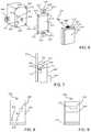
- FIG. 4is a block diagram of an expanded view of elements of an in-wall modular power adapter that is adapted to be installed in a junction box and to receive a wall plate;
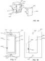
- FIG. 5is a block diagram of another in-wall modular power adapter
- FIG. 6is a block diagram of another in-wall modular power adapter having a metal plate comprising flanges for attaching the in-wall modular power adapter to a junction box;
- FIG. 7is a block diagram of an exemplary attachment element enabling the attachment of a control module to a portion of the switching module;
- FIG. 8is a plan view of the rear of a control module
- FIG. 9is a plan view of the front of a control module having a paddle-type toggle switch
- FIG. 10is a plan view of the front of a control module having a push-button toggle switch
- FIG. 11is a plan view of the front of a control module having a push-button toggle switch and a sensor
- FIG. 12is a plan view of the front of a control module having a push-button toggle switch and a display;
- FIG. 13is a plan view of the front of a control module having a plurality of pre-programmed or programmable buttons
- FIG. 14is an expanded view of a modular power adapter having a display on a switching module
- FIG. 15is an expanded view of a plug-in type modular power adapter having a cover for a control module
- FIG. 16is an expanded view of a plug-in type modular power adapter having a control module attached to a switching module;
- FIG. 17is a plan view of a junction box having a switching module adapted to interface with a control module of a wall plate;
- FIG. 18is a front plan view of a wall plate having a control module
- FIG. 19is a rear plan view of the wall plate of FIG. 18 ;
- FIG. 20is a rear plan view of a wall plate having two openings and two control modules
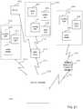
- FIG. 21is a block diagram of a system having a plurality of power adapters implementing different communication protocols.
- FIG. 22is a flow chart showing a method of implementing a modular power adapter
- FIG. 23is a flow chart showing a method of controlling power adapters using a plurality of different communication interfaces
- FIG. 24is a map showing the division of the geographical area of the map into a plurality of regions
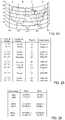
- FIG. 25is a table showing the definition of the plurality of regions and associated tables with the regions
- FIG. 26is an example of a table that could be implemented as any one of the tables of FIG. 25 ;
- FIG. 27is a diagram showing a switch of a module that is movable to provide a signal to a switching module to switch states
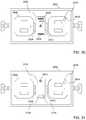
- FIG. 28is a plan view of a power adapter having a cover for a module between a pair of outlets;
- FIG. 29is a plan view of a power adapter having a cover (for a module between a pair of outlets) that is removed;
- FIG. 30is a plan view of a power adapter comprising a module having a plurality of connectors
- FIG. 31is a plan view of a power adapter having a wireless communication module
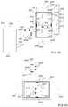
- FIG. 32is an expanded view of a power adapter, module and wall plate according to one embodiment
- FIG. 33is another expanded view of the power adapter and module of FIG. 32 rotated 90 degrees counter-clockwise;
- FIG. 34is another expanded view of a power adapter, module and wall plate according to one embodiment
- FIG. 35is another expanded view of the power adapter and module of FIG. 34 rotated 90 degrees counter-clockwise;
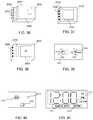
- FIG. 36is an exemplary module having an outlet
- FIG. 37is an exemplary module having a wireless communication circuit and a motion detector
- FIG. 38is an exemplary module having a wireless communication circuit and a user interface
- FIG. 39is an exemplary user interface having control actuators that could be implemented in the embodiment of FIG. 38 ;
- FIG. 40is an exemplary user interface having voice recognition that could be implemented in the embodiment of FIG. 38 ;
- FIG. 41is an exemplary user interface having a touch screen interface that could be implemented in the embodiment of FIG. 38 ;
- FIG. 42is an expanded view of a power adapter having a module and a wall plate according to another embodiment
- FIG. 43is a block diagram of a power adapter enabling the use of a dummy module according to one embodiment
- FIG. 44is a flowchart showing a method of implementing a module in a power adapter
- FIG. 45is a diagram showing the pairing of a power adapter with a control device
- FIG. 46is a diagram showing the pairing of another power adapter with a control device
- FIG. 47is a diagram showing paired power adapters on a first level of a building
- FIG. 48is a diagram showing paired power adapters on a second level of a building.
- FIG. 49is a flow chart showing a method of implementing a plurality of power adapters
- FIG. 50is a block diagram of a power adapter having a test circuit for testing connections to the power adapter
- FIG. 51is a block diagram of a circuit for testing the connections associated with a power adapter
- FIG. 52is another block diagram of a circuit for testing the connections associated with a power adapter
- FIG. 53is a block diagram a plurality of outlets having different connects to power lines
- FIG. 54is a block diagram showing a test module for testing the connections associated with a power adapter.
- FIG. 55is a flow diagram showing a testing the operation of a power adapter.
- the circuits, systems and methods set forth below and shown in the figuresrelate to power adapters, which may include “in-wall” adapters that are hard wired to electrical wires in a wall (such as to wires in a junction box for example) or plug-in adapters having prongs of a plug that are inserted into an electrical outlet.
- the circuits and methodsprovide a modular power adapter (as shown in FIGS.
- first portionwhich could be a switching portion or module for enabling the switching of power to a device controlled by the modular power adapter and may be wired into a junction box
- second portionwhich may be a control portion or module that controls the switching of power received by a switching portion and applied to a device receiving power from the power adapter (such as a porch light controlled by a power adapter hard wired into a junction box or a lamp plugged into a plug-in adapter for example, where the porch light and the lamp are commonly known as a load).
- the power adaptermay be implemented such that the first portion has switching elements that control the application of power to a load while the second portion provides signals to the first portion to control the switching elements.
- the second portionmay be removably coupled to the first portion by way of attachment elements, where the second portion may provide electrical signals to the first portion by way of contact elements of the second portion, such as pogo pins or other flexible contacts or rigid contacts, coupled to corresponding contact elements of the first portion, such as contact pads.
- the contact elementscould be placed on the first portion and the contact pads could be placed on the second element.
- guide or alignment elementscould be used on the switching module or the control module to align the modules.
- the modular power adapteris implemented to enable any one of a plurality of control modules (shown for example in FIGS. 3-8 ) to be coupled to the switching module, and control the switching operation of the switching module.
- the control modulecould be a toggle switch (such as a paddle-type toggle switch as shown in FIG. 4 ) with a dimming function.
- the control modulecould optionally include a wireless module for enabling wireless control by way of any short range wireless connection, such as a circuit for implementing any variation of a Bluetooth protocol or a Near Field Communication (NFC) protocol, or any local wireless network, such as a WiFi network or a wide area network, such as a cellular network.
- NFCNear Field Communication
- the wireless modulecould be a removable module coupled to the switching module or the control module, enabling changing a wireless communication protocol used by the modular power adapter.
- the control modulecomprises a motion detector having an on/off button.
- a further implementationmay comprise a simple on/off switch, which may comprise a status LED light to indicate the state of the load that is under control of the switch, such as a porch light that may not be visible, and an optional wireless control circuit and/or an optional display.
- any of the control portionsmay comprise a timer, which may have pre-programmed buttons or programmable buttons.
- a backup battery to maintain any timing patterns, such as schedules for applying power to a device,may be implemented on one or more of the switching portion or the control portion.
- the timing patternsinclude at least one on and off time, and may be associated with a certain day or date or group of days or dates.
- a displaywould be implemented as a part of the switching module, where other interface elements could be a part of a control module or split between the switching module and the control module. According to another implementation, the display could be a part of the control module.
- the control modulecould be attached to the switching module using any suitable attachment elements.
- the bottom of the control modulecould include a flange that could be inserted into a flange receiving portion of the switching module in a “ski-boot” fashion, where attachment element on one or more of the top or sides of the control module may be used to secure the control module to the switching module.
- the attachment elementcould be any type of latching element or threaded element that could receive a screw to secure the control module to the switching module.
- the attachment elementcould also include a flange, snap, strap, magnet, Velcro portion, or any other means for securing the control module to the switching module.
- the control modulemay have a flange extending from the sides around the perimeter or at least a portion of the perimeter to enable a user interface portion, which may include the display and any control actuators or elements, to extend through a recess in a wall plate.
- a user interface portionwhich may include the display and any control actuators or elements
- many conventional switch deviceshave a user interface portion of approximately 3.2 centimeters (cm) by 6.6 cm that extends through a recess or opening in the wall plate that is secured to the switch device and covers the junction box.
- the perimeter of the opening in the wall platemay abut the flange of the control module to help secure the control module to the switching module. That is, the user interface portion of the control module beyond the flange could extend through the opening of the wall plate.
- control modulecould extend into a recess of the switching module, where the perimeter of the opening of the wall plate would align with a flange or outer surface of a recessed portion of the switching module.
- control modulecould be removed while the wall plate is secured to the switching device.
- the modular nature of the modular power adaptermay not be evident to a user.
- the control modulecould (i) function as a cover for the switching module, (ii) could include openings to expose portions of the control module under the cover, or (iii) could be included under a cover generally having no other functionality.
- a front surface of the power adaptersuch as a surface of the recess of the switching module in an implementation having a recess, would include contact elements that would be coupled to corresponding contacts on the control portion to enable the control of a device using control signals coupled from the control device to the power adapter.
- a physical electrical connectionis shown by way of example, it should also be understood that communication of control signals or other signals could be achieved by another means, such as a wireless connection established between corresponding wireless communication circuits in the switching portion and the control portion. That is, in addition to any wireless connection between the control module and a wireless communication device, such as a smart phone or tablet computer for example, there may be a wireless connection, such as a Near Field Communication (NFC) connection, between the control module and the switching module.
- NFCNear Field Communication
- control modulecould be configured to provide multi-mode communication with communication devices external to the control module, such as multiple modules including both a WiFi module and a Bluetooth module for example. That is, a user could provide control signals from a communication device such as a smart phone or tablet computer using either a WiFi connection or a Bluetooth connection.
- the control module and/or the switching modulecould include a connector for receiving a portable memory device, such as a USB thumb drive, to download data, including timing patterns, operational information (e.g. at least one of time, data or location), firmware updates, or any other data which may enable the operation of the modular power adapter.
- control modulecould be incorporated as a part of the wall plate as shown for example in FIGS. 11-14 , enabling the implementation of a single switch module, where different control modules can provide different functionality.
- the single switch modulecould a simple toggle switch (or a paddle-type switch that fills the approximately 3.2 cm by 6.6 cm opening of the wall plate), where different control modules would interface (directly or wirelessly) with the switch module.
- contacts on the control module (on the wall plate)could align with contracts on the switch module adjacent to the switch portion.
- the different control modulescould provide different functionality, such as dimmer functionality or timer functionality. Some control modules could provide multiple functionality.
- the control modulecould be an integral part (i.e.
- the wall switch platecould be configured to receive multiple control modules. For example, a control module could be placed on either side of the opening of the wall plate, where a second set of contact elements would be placed on the opposite side of the switch module of the first set of contact elements.
- One benefit of the implementation of wall plates with control portionsis that a single type of switch module could be implemented, and would be functional, without a control module. That is, if the basic switch module were implemented, and a conventional wall plate with no control module were used, a user could still use the basic switch module, which may only have on/off functionality. While the contact elements would not be used, a user could later add functionality of the basic switch module by using a wall plate that has a control module. Such an arrangement could also work with an outlet, where timing or dimmer functionality could be provided for one or more of the receptacles of the outlet. Control modules could also be implemented in wall plates having more than one opening, where different control modules can be implemented for switching modules associated with different openings of the wall plate.
- one or more security featuresmay be employed that would require that the control module and the switching module be paired.
- it may be necessary to authenticate the control moduleby provide a security code from the control module to the switching module to ensure that the control module is authorized to operate with the switching module.
- the security codecould include a unique serial number and may be encrypted.
- the security codemay also include a field that indicates the type of control module and provides information related to the functionality of the control module.
- a usermay also be required to perform a certain operation when replacing the control module, such as implementing a reset procedure using reset buttons on one or both of the control module and the switching module.
- datamay be downloaded from the control module to the switching module or vice versa to enable the switching module to function with the control module.
- the datamay be operational data (i.e. data associated with features controlled by the switching module), or security or identification data (i.e. data indicating the identity of the control module or authorizing the use of the control module).
- a single controllercan provide multimodal control of different control devices and different sets of control devices, such as the modular power adapters as described above or other timers or lighting control devices.
- the single controllercould be for example a smart phone, a tablet computer or any other computer or device enabling a wireless connection to multiple control modules by way of different wireless protocols.
- the controllercould communicate with a first set of control devices by way of a first wireless connection and a second set of control devices by way of a second set of connections.
- the controllercould communicate with any number of groups of devices on corresponding sets of communication protocols.
- a first set of devicescould communicate with a control device by way of a Bluetooth connection, where the devices could be implemented in a Bluetooth mesh network.
- the devices of a first setcould be implemented in different locations, such as an indoor device, an outdoor device, a device controlling a specific device, such as a water heater or an under-cabinet lighting fixture.
- a second set of devicescould include devices that are controlled by the controller using another local area network, such as a WiFi network.
- the second set of appliances controlled by the devicescould include the types of devices that a user may desire to access from a remote location, such as a curling iron, a coffee machine, a particular lamp or a wireless-controlled door lock.
- these devicesmay be devices that a user may wish to check to make sure that they have been turned off, or the types of devices that a user may wish to turn on while they are away.
- a third set of devicescould be other specialty devices such as pool controls or specialty lighting. These devices could be controlled by an appropriate wireless connection.
- the controllercould also control devices by way of a proprietary network, such as connection using a Z-Wave or a ZigBee controller. That is, the system could be integrated with an existing system employed by the user, such as a Z-Wave or ZigBee system for example.
- a single controllercan control a plurality of devices using a plurality of different connections implementing different wireless communication protocols.
- different communication protocolsit is possible to implement the different devices with the most suitable communication protocol from a single controller.
- a WiFienables remote access
- itmay also be more susceptible to hacking or other security issues.
- a Bluetooth connectionbecause of its short-range nature, may have fewer hacking or security issues, but is generally not remotely accessible.
- a modular power adapter 100comprises a switching module 102 for controlling the application of power to a load (such as a light, appliance, or other device receiving power by way of an outlet, also known as a receptacle, or other contact elements applying power of the switching module) and a control module 104 that is in communication with the switching module.
- the switching module 102is coupled to receive a power input signal, which may be power from an outlet to which the modular power adapter is plugged in or power from wiring in a residential or commercial building in which the modular power adapter is implemented for example.
- the output poweris provided to an output such as an outlet into which a plug of an appliance or other device can be plugged or wires that are coupled to a device such as a light fixture for example.
- a light, appliance or other device receiving output power from the outputis commonly called a load.
- the control module 104may receive one or more of user interface input signals and wireless signals, as will be described in more detail below. While the modular power adapter 100 is shown as having two modules, it should be understood that the modular power adapter could contain more modules, where one of the switching module and the control module could be divided in sub-modules.
- the control modulecould include a control portion and a wireless communication portion. That is, the control portion may include user interface elements, such as buttons or a display, and may be adapted to receive an optional wireless communication module.
- FIG. 2another block diagram of a modular power adapter is shown.
- the block diagram of FIG. 2shows elements of a modular power adapter, such as the modular power adapter of FIG. 1 for example.
- a control circuit 202is coupled to various elements of the switching module 102 to enable communication with the control module 104 and control the operation of the switching module.
- a transformer 204is coupled to an input port 206 to receive an input voltage that enables providing power to a load by way of an output of the switching module.
- the input portcomprises contact elements that could be for example wires or connector screws that are wired into a junction box or could be prongs of a plug adapted to be inserted into electrical outlet in a wall of a residential or commercial building.
- the transformer 204provides power to the control circuit 202 by way of a power line 207 .
- the control circuitalso receives a ground potential at a ground terminal 208 , which may be another contact element such as a ground wire or ground contact, or a ground prong of a plug of the switching module for example.
- the control circuit 202may also receive power by way of a backup battery 209 to retain any information such as operational information or timing patterns.
- a different source of backup powercould be implemented, such as a capacitor for example.
- An input portion 210may be implemented to enable the input of information or the selection of timing patterns (in an implementation having user interface elements on the switching module such as the implementation of FIG. 14 for example), and may include a control button or pairing button for enabling the pairing of the switching module and the control module as will be described in more detail in reference to FIG. 4 .
- a memory 212is coupled to the control circuit and may store operational information and timing patterns.
- An oscillator 213may be coupled to the control circuit to enable the control circuit to maintain a current time.
- a switch 220is coupled to receive power from the transformer by way of a power line 222 and provide power to an output 223 (which may be another contact element that is coupled to a load such as by a wire) in response to control signals associated with a timing pattern on a line 224 from the control circuit.
- the output 223may be an outlet that receives a plug for the device controlled by the modular power adapter (or wires or screws that can be coupled to wires in the case of an in-wall power adaptor that are coupled to a device (i.e. load) that is powered by the power adapter).
- a wireless communication circuit 226could be used to receive various information, such as operational information, programming data, or firmware updates from the control module 104 or some other source, as will be described in more detail below.
- the input portion of the modular power adaptermay also include the connector for receiving the portable memory device such as a USB thumb drive or an SD memory to download any type of data, such as operational information, programming data, or firmware as will be described in more detail below.
- the switching module 102 and the control module 104may communicate by way of a communication port 227 , which may be a connector or a plurality of contact elements, as will be described in more detail in reference to FIG. 4 .
- the communication port 227enables a communication link 228 with a communication port 229 , which may also be a connector or a plurality of contact elements.
- the communication linkmay comprise contact elements of the communication ports 227 and 229 to enable the transfer of communication signals between the communication ports.
- the communication linkmay also provide power to power elements of the control module.
- the communication link 228may be a wireless communication link, where the communication ports comprise wireless communication circuits.
- the control module 104comprises a control circuit 232 , which may be any type of processing circuit for (i) receiving inputs, such as by way of an input portion 234 , and (ii) controlling the operation of the control module 104 .
- the input portioncould be implemented as shown and described in reference to FIGS. 9-13 for example.
- a battery 236 or some other source of energy such as a capacitormay be used to power the control module 104 or function as a backup power source if the control module 104 receives power by way of the communication port 229 , rather than by way of a power source internal to the control module 104 .
- a wireless communication circuit 248which may be a wireless receiver or both a wireless transmitter and receiver (i.e. a wireless transceiver), comprises an antenna 250 .
- Data received by the wireless communication circuit 248may be provided to the control circuit 232 , or data generated by the control circuit 232 may be transmitted by the wireless communication circuit 248 .
- Datasuch as a timing pattern or operational information entered by the input portion or received by way of the wireless communication circuit 248 , may be stored in a memory 242 .
- the wireless communication circuit 248may be any type of receiver for receiving wireless communication signals, such as GPS receiver, a cellular receiver, a radio frequency (RF) receiver, or any type of receiver adapted to receive operational information, programming data or any other type of information such as software updates.
- the operational informationmay be provided to the control circuit to enable the operation of the control circuit and the implementation of the timing patterns on the remote switching device.
- the wireless communication circuitcould be a global positioning system (GPS) receiver, a cellular receiver for a cellular telephone network, or a receiver for some other wireless network.
- GPSglobal positioning system
- a GPS receiveris commonly available from SiRF Technology, Inc, for example, while a cellular receiver could be implemented in an integrated circuit chip or module, such as a chip or module available from u-blox Holding AG of Thalwil, Switzerland. Therefore, actuators for entering time, date and location information in the various implementations of programming interfaces could be eliminated with the use of a wireless communication circuit 248 , which may be a receiver or a transceiver having both a receiver and a transmitter.
- the wireless communication circuit 248 for receiving communication signals from a remote network such as a GPS network or a cellular networkis shown as a part of the control module 104 , the wireless communication circuit 248 could be implemented as a part of the switching module 102 .
- An oscillator 244 or some other device for keeping a time for the devicemay be coupled to the control circuit, where a current time or other data may be displayed on a display 246 . While separate oscillators are shown in the switching module 102 and the control module 104 , it should be understood that a single oscillator could be implemented, and an oscillating signal or other signal based upon the oscillating signal could be shared between the switching module 102 and the control module 104 .
- the control circuit 104may also comprise a wireless communication circuit 252 having an antenna 254 enabling the communication of signals with a corresponding wireless communication circuit 226 (having an antenna 260 ) of the switching module by way of a wireless communication link 256 .
- a wireless communication circuitthat could be implemented for wireless communication circuits 226 and 252 is shown by way of example in FIG. 3 . While both a physical connection for transferring signals and/or power is provided by way of the communication link 228 and a wireless communication link 256 is provided by way of the corresponding wireless communication circuits 226 and 252 , it should be understood that one or both of the communication links could be implemented.
- a test circuit 260coupled to the communication port 227 and the control circuit 202 , as will be described in more detail below in reference to FIGS. 49-53 .
- FIG. 3a block diagram of a wireless communication module of the modular power adapter of FIG. 2 is shown.
- the antenna 304receives wireless communication signals according to a predetermined wireless communication protocol.
- the datawhich may include programming data and operational information, may be sent from the control module to the switching module.
- datamay be sent from the switching module to the control module.
- power usage data associated with a device controlled by the switching modulemay be transferred to the control module.
- Other datasuch as pairing commands and information, status information, or other information, may be received from a remote server as will be described in more detail in reference to FIG. 21 .
- the received datais coupled to a combined mixer/voltage controlled oscillator 306 , the output of which is coupled to an intermediate frequency (IF) circuit 308 .
- IFintermediate frequency
- PLLphase locked loop
- ADCanalog-to-digital converter
- a control circuit of the switching module 102 or the control module 104may also provide data for transmission to the other of the switching module 102 or control module 104 .
- Data to be transmitted from the wireless communication circuitis coupled to a digital-to-analog converter (DAC) 316 , the output of which is coupled to a modulator 318 which is also coupled to a PLL 320 .
- a power amplifier 322receives the output of the modulator to drive the antenna 304 and transmit the data.
- the data transceiver of FIG. 3could implement the IEEE Specification 802.11 (WiFi) wireless communication standard, any Bluetooth standard, an infrared protocol, a Near Field Communication (NFC) standard, or any other wireless data protocol. While the circuit of FIG. 3 is provided by way of example, other wireless data transceivers could be employed according to the present invention to implement the desired wireless communication standard.
- WiFiIEEE Specification 802.11
- NFCNear Field Communication
- FIG. 4a block diagram of an expanded view of elements of an in-wall modular power adapter that is adapted to be installed in a junction box and to receive a wall plate is shown.
- a junction box 402is coupled to conduit 404 having wires 406 that may be used to provide power to the modular power adapter by way of a terminal portion 408 of the wires that extend into a recess 410 adapted to receive the modular power adapter.
- Flanges 412 and 414receive a screw or other attachment element by way of a threaded portion 416 to enable attaching corresponding flanges of the modular power adapter to the flanges 412 and 414 .
- the switching module 102comprises a front surface 424 that defines a recessed portion 426 extending from the front surface to a back wall 427 .
- the switching module 102may also comprise a flange recess 428 at the bottom of the recessed portion behind the front surface 424 .
- the flange recess 428is adapted to receive a corresponding flange of a control module 104 .
- the switching portionmay also comprise an attachment element 430 adapted to be coupled to a corresponding attachment element of the control module.
- the switching modulemay also comprise flanges 432 having a threaded portion 434 for receiving a screw to secure a wall plate to the modular power adapter and a hole 436 for receiving a screw that can be inserted into the threaded portion 416 and can be used to secure the switching module 102 to the junction box 402 .
- User interface elements and other elementsenable a user to implement the switching module with a control module within the recess 426 , such as a back wall of the recess for example (or on another surface accessible by a user in an implementation not having a recess).
- a communication port 438which may comprise a connector or a plurality of contact elements for example, may be implemented.
- the contact elementsmay be contact pads adapted to be in electrical contact with contact elements of the control module, where the contact elements may be spring loaded contacts such as pogo-pins, or other flexible or spring loaded contacts that extend from a back surface of the control module and align with and make electrical contact with the contact pads of the switching module.
- contact padscan be implemented on the control module and the corresponding contacts can be implemented on the back of the recess of the switching module. While the contact elements are indicated as being on the back surface of the switching module and the control module, it should be understood that the contacts can be placed on other surfaces, such as a side of the switching module and a side of the control module.
- the switching modulemay also comprise a control button 440 , which may function as a reset button or a pairing button for enabling the pairing of the control module with the switching module.
- the control buttonmay be used to reset the switching module, enabling the switching module to receive new data associated with a control module, and therefore to enable the switching module and the control module to communicate and control a device receiving power from the switching module.
- the control button 440could also enable a pairing function to pair an authorized control module to communicate with the switching module. That is, a pairing function can be implemented, wherein a control button on each of the switching module and the control module can be selected to enable the transfer of information between the control module and the switching module. It may be necessary to charge the control module by coupling the control module to the switching module to enable the control module to perform a reset operation of the control switch and to enable a pairing of the control module with the switching module.
- the pairing operationis beneficial to ensure that only an authorized control module is implemented to prevent for example unauthorized control of a control module which may have a wireless control feature.
- the control of the device receiving power from the switching modulemay be compromised, and unauthorized use of a device under the control of the switching module may occur.
- the switching module and the control modulemay communicate to enable the proper operation of a load controlled by the switching module.
- a control circuit of the switching modulemay detect the type of device controlled by the switching module, such as the type of light bulb (e.g.
- the control modulecan detect the type or qualities of the light bulb by way of the communication ports of the switching module and the control module.
- a wireless communication module 442(shown in dashed to indicate that it may be behind the back wall 427 of the recess) may also be implemented in the switching module.
- the wireless communication module 442could be for example the wireless communication module 226 of FIG. 2 for example.
- a memory port 444which may be a USB port or a port for receiving another type of memory card, such as an SD card, may be implemented on the switching module, and may receive any type of information, such as operational information, timing patterns for turning the device controlled by the power adaptor on or off, or other data that is beneficial in implementing the operation of the control module.
- a timing patternmay include for example on and off times for a timing feature of the modular power adapter.
- USB portis shown on the switching module, it should be understood that a USB port could instead be implemented on the control module, or implemented on the control module in addition to a USB port on the switching module.
- Wires 446 for receiving ground and power signals providing current to a loadalso extend from the switching module. While wires are shown, contact elements adapted to receive wires in a junction box such as a screw for securing a wire to the switching module, could also be implemented.
- the control module 104may comprise a rear portion 450 that is inserted into the recess 426 and a flange 452 that abuts the front surface 424 .
- a front surface of the flange 452provides a surface to abut a perimeter edge 460 of an opening 462 of a wall plate 459 , enabling a control interface 454 , which may be a user interface according to the implementations of FIGS. 9-13 , to extend through an opening 462 of the wall plate.
- the control module 104also comprises a flange 456 according to the implementation of FIG.
- control module 4enabling the control module to be attached to the switching module using a “ski-boot” arrangement, where the flange is inserted into the corresponding flange recess 428 and an attachment element 458 is attached to the attachment element 430 .
- the communication port of the control modulealigns with the communication port of the switching module to enable the communication of at least one of control signals and power between the switching module and the control module.
- the wall plate 459can be attached to the switching device using holes 464 , where the holes receive screws that can be inserted into threaded portions 434 of the flanges 432 .
- the dimensions of the various elements of modular power adapterare selected to enable the modular power adapter to be attached to a junction box, such as a conventional residential junction box. Therefore, the width w s of the switching module may be selected to be less than the width of a conventional residential junction box, and the height h s may be selected to be less than the height of a conventional residential junction box.
- a depth ds of the recess 426is also selected to ensure that, when the control module is attached to the switching module, the contact elements of the communication ports provide an adequate electrical connection to enable the transfer of data signals and/or power signals.
- the contact elements of the communication portsensure that adequate pressure between contacts and contact pads will enable an electrical connection.
- the dimensions of back portion 450 of the control modulehas a width w c and a height h c that are just slightly less that the width w s and the height h s to ensure that the control module fits into and aligns with the switching module.
- the dimensions of a front portion 454are also selected to extend through opening 462 in a wall plate, and ensure that the edges of the opening of the wall plate abut the flange 452 of the control module.
- a flange 456 of the control moduleis adapted to be inserted into the flange recess 428 of the switching module.
- the connector element 458is adapted to be secured to a corresponding connector element 430 of the switching module 102 .
- the edges 460define opening 462 . Because the height h p and the width w p of the opening 462 are slightly greater that the height h c ′ and the width w c ′ of the front portion 454 ′, the front portion 454 can extend through the opening 462 , where the edges 460 of the recess 462 will abut the flange 452 . Outer edges 459 and 460 of the wall plate extend beyond the perimeter of the junction box to cover the junction box.
- FIG. 5a block diagram of another in-wall modular power adapter is shown.
- the control moduleis attached to the switching module such that some sides of the two modules may be generally aligned, where a front portion of the control module is adapted to fit through the recess of the wall plate and a back portion of the control module acts as a flange that abuts the edges of the opening of the wall plate.
- the switching module of FIG. 5generally comprises a planar front surface that abuts a corresponding planar back surface of the control module.
- Elementsmay protrude from a planar surface of the switching module or the control module, or may be recessed within a planar surface, such as a connector protruding from or being recessed in a planar surface.
- the connector element 438 or the memory port 444may protrude from or be recessed in the planar surface 502 , while the control button 440 may be flush with the planar surface 502 .
- Attachment elements 504 and 506may be adapted to couple with corresponding connector elements 507 , which may be located at the top and bottom of the control module for example.
- the sides of a back portion 508 of the control modulemay align with sides of the switching module, where a surface 510 adjacent to a front portion 512 acts as a flange for the wall plate.
- the attachment elements 504 and 506can be integrated in the planar surface 502 or can be integrated in the flanges 432 .
- FIG. 6a block diagram of another in-wall modular power adapter having a metal plate comprising flanges for attaching the in-wall modular power adapter to a junction box is shown.
- a plate 602which may be a metal plate for example, can be attached to the switching module 102 and comprises connector elements to allow the control module 104 to be attached to the plate, and therefore interface with the switching module.
- the switching modulemay comprise threaded portions 604 - 608 adapted to receive screws that would extend through corresponding holes 616 - 622 to enable the plate to be attached to the switching module.
- the platealso comprises an opening 623 enabling back portion of the control module to extend through the opening 623 .
- the plate 602also comprises flanges extending from the top and bottom to enable attaching the modular power adapter to a junction box.
- a first flange 624comprises a hole 626 for receiving a screw to be screwed into a threaded portion of the junction box.
- the flangealso comprises a receptacle 628 , such as a threaded portion, for a screw to enable attaching a wall plate to the modular power adapter.
- the platemay also comprise an attachment element 630 adapted to receive a corresponding attachment element of the control module.
- a second flange 632 extending from the bottom of the platecomprises an attachment element 638 .
- the control modulecomprises a back portion 640 extending to a flange 642 that defines a front portion 644 .
- a front surface 646may comprise a user interface that is accessible to a user.
- An attachment element 648 that is adapted to couple with attachment element 630is provided on the control module, such as on the back portion of the control module as shown.
- An example of an attachment element comprising corresponding attachment elements of the switching module and the control moduleis shown and described in reference to FIG. 7 .
- FIG. 7a block diagram of an exemplary attachment element enabling the attachment of a control module to a portion of the switching module is shown.
- the rear portion 640comprises a latching element 702 having a lever portion 704 and a pivot element 706 that enables a latching portion 708 having a beveled edge 710 to secure the control module to the flange 624 .
- the attachment element 630 of the flange 624comprises a receiving element 712 and a flange 714 adapted to receive the beveled edge 710 .
- the attachment elements of the flange and control module of FIG. 7provide one example of a means for attaching the control module to a portion of the switching module or flange, it should be understood that the control module could be attached to some other portion of the modular power adapter.
- FIG. 8a plan view of the rear of a control module is shown. More particularly, contact elements 802 that may be coupled to or in electrical contact with the corresponding contact elements 438 of the switching module are shown on a back surface of the control module.
- a control button 804which may be a pairing button for example, is also implemented. As described above in reference to FIGS. 4 and 5 , the contact elements 802 may be contacts extending from the back surface, or contact pads that may be flush with the back surface or recessed.
- FIGS. 9-13exemplary user interface portions of a control module are shown. While examples of user interfaces are provided, it should be understood that the user interfaces could include any type of user interface element enabling the operation or control of a power adapter, including the application of power to a device controlled by the power adaptor.
- FIG. 9a plan view of the front of a control module having a paddle-type toggle switch is shown. That is, a movable element 902 enables changing the state of a device controlled by the control module.
- the movable element 902may be movable between a first position for an on state and a second position for an off state.
- the top portion of the movable elementwhen in the on state, the top portion of the movable element may by flush with the wall plate. Similarly, in the off state, the bottom portion of the movable element may be flush with the wall plate. That is, a user could determine the state of the switch based upon a position of the paddle-type toggle switch. Alternatively, after a user selects either the top or the bottom of the paddle-type toggle switch, it would return to a normal resting position which does not indicate a state of the device, but rather where the switch is used for changing the state of the device.
- the control module of FIG. 9communicates a change of state of the switch by way of contact elements 802 .
- a metal element of the control modulemay short two of the contracts of contacts elements 802 , enabling the switching module to determine that a change of state is desired.
- depressing the top portionmay provide a path to ground for a first contact of the contact elements 802 , indicating that a user desires to turn the light on
- depressing the bottom portionmay provide a path to ground for a second contact of the contact elements 802 , indicating that a user desires to turn the light off.
- One or more wireless receivers 248may be included in the switch of FIG.
- the switch of FIG. 9can be a mechanical switch that enables generating an electrical signal at the contact elements 802 , where the electrical signal is decoded by a control circuit of the switching module. That is, according to some embodiments, the control module generates an electrical signal that is detected by the switching module, rather than making a physical connection to engage an actuator of the switching module for example to change a state of the switching module.
- the control modulemay include a circuit such as a wireless receiver or other control circuit for providing signals to the switching module.
- FIG. 10a plan view of the front of a control module having a push-button toggle switch is shown.
- the state of a device controlled by the switchcan be changed by a button 1002 , which may include a status indicator 1004 , such as an LED for example.
- the button 1002may be movable between a depressed state, where the switch will be pressed in when the switch is turned on, and a state where the button is flush with the front of the control module when the switch is turned off.
- the status indicatormay also indicate whether a bulb is out; such as by flashing.
- the 10may also comprise a wireless receiver 248 , as described above in FIG. 9 .
- the buttonmay operate as an mechanical element an electrical signal at the contact elements 802 , where the electrical signal is decoded by a control circuit of the switching module as described above in reference to FIG. 9 .
- FIG. 11a plan view of the front of a control module having a push-button toggle switch and a sensor is shown.
- a sensor 1102can be implemented on the front portion of the control element.
- a motion detector or an ambient light detectorcould be implemented on the front panel to automatically change the state of the switch based upon the detection of motion or the detection of a state of the light at the switch.
- the switch 1002 and the sensor 1102could be implemented with timing functions of a programmable timer (i.e. a control circuit implementing a timing pattern for the power adapter).
- FIG. 12a plan view of the front of a control module having a push-button toggle switch and a display is shown.
- a display 1202may be implemented on the front surface of the control module. While a sensor is not shown in the implementation of FIG. 12 , it should be understood that a sensor, such as the sensor of FIG. 12 , could be implemented with the implementation of FIG. 12 .
- FIG. 13a plan view of the front of a control module having a plurality of pre-programmed or programmable buttons is shown. As shown in the implementation of FIG. 13 , a plurality of buttons could be implemented on the front surface of the control module.
- the control module 104may comprise a display 1302 having a time portion 1304 , where the time portion of the display may indicate the current time or a time that is being programmed for example.
- the displaymay also include an AM/PM indicator 1308 , and on/off indicator 1310 , a date indicator 1312 and a location indicator 1314 .
- control devicecould be programmed using a user interface, such as the user interface shown in FIG. 13 .
- the user interface of the control device of FIG. 13includes programmable buttons and pre-programmed buttons. More particularly, a programming portion 1324 of the user interface comprises a first programming button 1326 , which could be used for cursoring up while programming or turning on a light or other device controlled by the control module 104 (when not in a programming mode), and a second programming button 1328 , which could be used for cursoring down during a programming operation or turning off the light or other device controlled by the control device (when not in a programming mode). While the first programming button 1326 and the second programming button 1328 are shown as multifunction buttons for programming and controlling the device, it should be understood that one or more buttons having on and off functionality could be implemented separate from the first and second programming buttons.
- a timer control portion 1330comprises a first programmable button 1332 , which may be programmed with an on time for a timing pattern, and a second programmable button 1334 , which may be programmed with an off time for the timing pattern.
- the on time associated with the first programmable button 1332may be programmed using the first programming button 1326 and the second programming button 1328 to cursor up and cursor down to reach the correct time that a user desires to turn on a device controlled by the control module 104 .
- the off time associated with the second programmable button 1334may be programmed using the first programming button 1326 and the second programming button 1328 to cursor up and cursor down to reach the correct time that a user desires to turn off a device controlled by the control module 104 .
- first programming button 1326 and the second programming button 1328are shown as having only an on time and an off time respectively, where the buttons may be used together (i.e. when one of the buttons is selected, both will be selected), each of the first programming button 1326 and the second programming button 1328 could be programmable to have both an on time and an off time.
- buttonsthat when selected, will implement switching data associated with a pre-programmed switching pattern.
- an “Evening” button 1336could be selected to turn on the lights between 6:00 PM and 11:00 PM or between dusk and 11:00 PM for example.
- a “Morning” button 1338could have pre-programmed on and off times associated with hours that a user may desire to have lights on during the morning, such as between 5:00 AM and 8:00 AM for example.
- An “All Night” button 1340could, when selected, turn on the lights at some time during the evening, such as a fixed time of 5:00 PM or a variable time such as dusk, and could turn the lights off at some time in the morning, such as 8:00 AM or a variable time such as dawn.
- a countdown functioncould also be implemented, where a device controlled by the timer may be on for predetermined intervals based upon the number of times the countdown button 1342 is selected.
- An indicator 1342such as an LED, could be implemented to indicate when a certain pre-programmed button has been selected. The countdown function could also be accomplished using cursor buttons for scrolling up or down to select a countdown time.
- a reset button, 1344which may be a recessed button for example, enables resetting the timer to a default state. It should also be noted that while a pre-programmed button has a particular default setting for on and off times when a user acquires the timer, the pre-programmed buttons may be reprogrammed by a user to have different on and off times. For example, a user may decide that preferred times for an evening setting may be between 5:00 PM and midnight, where the user could reprogram the button to go on at 5:00 PM and off at midnight rather than 11:00 PM.
- different user interface featuresare shown by way of example, it should be understood that features of different embodiments can be combined to include a variety of different features.
- FIG. 14an expanded view of a modular power adapter having a display on the switching module is shown.
- a display 1402is provided on the switching module, where the control module comprises control circuits for controlling the operation of the switching module and any user interface elements that may be present on the front of the control module.
- a recess 1404may be provided behind the front surface and below the display to receive a flange 1406 , where an attachment element 1408 can be coupled to a corresponding attachment element 1410 on the switching module. That is, because of the location of the display, it may be beneficial to attach the control module at the bottom of the switching module.
- the rear portion 1412will then be positioned within the recess 1414 .
- the front portion 1416is configured to extend through an opening in the wall plate.
- Contact elements 1418 on the back of the rear portion 1412shown here in a dashed box, are positioned to make contact with corresponding contacts 438 .
- FIG. 15an expanded view of a plug-in type modular power adapter having a cover for a control module is shown.
- the plug-in type modular power adapter of FIG. 15comprises a switching portion 1502 that is similar to the switching portion of an in-wall modular power adapter, except that the wires or contact screws that are used to wire the in-wall adapter are replaced with a plug and a receptacle by way of example.
- the power adapter of FIG. 15also comprises a control portion 1504 that is adapted to attach to the switching module and a cover 1506 as shown that is adapted to cover the control portion 1504 .
- the switching modulecomprises prongs 1508 of a plug to be inserted into a wall outlet, and a receptacle 1510 for receiving a plug of a device controlled by the power adapter.
- a recessed portion 1512is adapted to receive the control module 1504 .
- a communication circuit 1518may be located behind a rear wall 1519 of the recessed portion 1512 , which may also comprise contacts 1520 that are adapted to align with corresponding contacts of the control module.
- a recess 1522may be adapted to receive a corresponding flange 1524 , where an attachment element 1526 is positioned to align with a corresponding attachment element 1528 of the control module.
- Attachment elements 1530 , 1532 , 1534 , and 1536are positioned to receive corresponding attachment elements on the cover 1506 , where attachment elements 1538 and 1540 of the cover 1506 are adapted to align with and attach to attachment elements 1530 and 1532 , respectively.
- the attachment elements on the cover 1506may comprise flanges that are inserted into recesses of the attachment element of the switching module, where the sides of the cover can be squeezed toward the center to release the flanges and remove the cover.
- FIG. 16an expanded view of a plug-in type modular power adapter having a control module attached to a switching module is shown.
- the control module 1602also functions as the cover, where attachment elements 1604 and 1606 are adapted to be received by attachment elements 1530 and 1532 .
- Attachment elements that are similar to attachment elements 1604 and 1606are provided on the opposite side of the control module 1602 to attach to attachment elements 1534 and 1536 .
- User interface elementsmay be implemented on the control module 1602 , such as on a front surface 1608 .
- the control module and user interface elementscould be implemented as described above with respect to the in-wall power adaptor.
- FIGS. 17-20various implementations of a modular power adapter for in-wall applications includes a wall plate having control circuitry, such as a control module.
- a wall platehaving control circuitry, such as a control module.
- FIG. 17a plan view of a junction box 1701 having a switching module 1702 adapted to interface with a control module of a wall plate is shown. As shown in FIG. 17
- a switching module 1702comprises flanges for attaching the switching module to the junction box, such as a first flange 1706 having a recess 1708 for receiving a screw to attach the switching module to the junction box and a threaded portion 1709 for receiving a screw for attaching a wall plate to the switching module, and a second flange 1710 having a recess 1711 for receiving a screw to attach the switching module to the junction box and a threaded portion 1712 for receiving a screw for attaching a wall plate to the switching module.
- a switching element 1714shown here as a paddle-type toggle switch, enables changing the state of the device controlled by the switching module 1702 . As will be described in more detail in reference to FIGS.
- an edge of an opening of a wall plate having control circuitryoverlaps with a portion of the control module, and may extend up to an overlap region shown by the dashed line 1715 .
- Contact elements 1716which are shown beyond (i.e. outside of) the dashed line 1716 , and therefore would be under the wall plate when the wall plate is attached to the switching module.
- the contact elements 1716are positioned to align with corresponding contact elements of a control module of the wall plate, which will be described in reference to FIG. 18 .
- FIG. 18a front plan view of a wall plate having a control module is shown.
- a wall plate 1802comprises an opening 1804 that enables a switching element 1714 to extend through the wall plate, where an edge 1806 would extend to approximately the dashed line 1715 to cover the edges of the switching module.
- a control module 1808shown in dashed lines to indicate that it is on a rear surface of the wall plate, includes contact elements 1810 to align with and electrically couple to corresponding contact elements 1716 . Screw holes 1812 enable screws to be used to attach the wall plate to the switching module.
- FIG. 19which provides a rear plan view of the wall plate of FIG.
- attachment elements 1902enable the control module 1808 to be removably attached to the wall plate. That is, the attachment elements 1902 would enable the control module 1808 to be switched out with a different control module to provide flexibility in the operation of the switching module. For example, a control module having a different wireless communication protocol could be attached to the wall plate, making it easy to change the functionality of the switching module without having to remove the switching module, which can costly and time consuming in the case of an in-wall power adapter.
- FIG. 20a rear plan view of a wall plate having two openings and two control modules is shown.
- a first control module 2002may be associated with a first opening 2004 of the dual-wall plate opening
- a second control module 2006may be associated with a second opening 2008 . While two openings are shown, it should be understood that any number of openings can be implemented.
- a single central controller 2102can provide multimodal control of different control devices or different sets of control devices, such as the modular power adapters or other timers or lighting control devices.
- the control devicescould be power adapters or other suitable control devices that could be coupled to control a device or integrated in the device to control the device.
- the single controller 2102could be for example a smart phone, a tablet computer or any other computer or device enabling a wireless connection to multiple control modules by way of different wireless protocols.
- the controller 2102could communicate with a first set 2104 of control devices, a second set 2106 of control devices, and a third set of control devices 2108 .
- the first set of control devicesmay include an outdoor light 2110 , an indoor light 2112 , and a water heater 2114 that are controlled by way of a first wireless connection 2116 .
- the central controller 2102is directly in communication with devices of the first set of devices using a short range communication protocol. That is, there is no intervening control element, such as a base station or wireless hub, that receives control signals from the central controller and provides control signals to the control devices.
- a first set of devicescould communicate with central controller by way of a Bluetooth connection, where the devices could be implemented in a Bluetooth mesh network, or a near field communication (NFC) link.
- the short range communication protocolmay be accessible at a distance of approximately 100 feet for example.
- the devices of a first setcould be implemented in different locations, and could include for example an indoor device, an outdoor device, a device controlling a specific device, such as a water heater or an under-cabinet lighting fixture.
- the first set of control devicescould be associated devices that a user does not wish to access remotely, or a device about which the user may have security concerns and may not want to have controlled by a lower security protocol, such as a IEEE 802.11 communication protocol, also known as WiFi.
- the first communication protocolmay therefore be a local communication protocol, and more particularly a direct local communication protocol.
- the second set 2106 of control devicesmay be controlled by way of a second connection, which may be for example a network.
- the second set of devices 2106could include devices that are controlled by the controller using a local area network, including a base station or wireless hub that communicates with a plurality of devices.
- the local area networkcould be a WiFi network including a WiFi base 2118 enabling communication links 2120 and 2121 .
- the local area networkcould also be accessible by a wide area network such as a cellular network to enable remote access to devices.
- the WiFi networkcould be any network implementing any IEEE 802.11 standard for example.
- the second set of appliances controlled by the devicescould include the types of devices that a user may desire to access from a remote location, such as an indoor light 2122 , a curling iron 2124 , a coffee machine 2126 , a particular lamp, or a wireless-controlled door lock 2128 . That is, these devices may be devices that a user may wish to check to make sure that they have been turned off, or the types of devices that a user may wish to turn on while they are away.
- the third set of devices 2108could be controlled by another wireless base 2130 enabling communication links 2132 and 2134 to control other specialty devices such as pool controls or specialty lighting.
- an outdoor light 2136 , and indoor light 2138 , and a pool heater 2140could be controlled by the wireless base 2130 .
- the wireless base 2130could be a Z-Wave or a ZigBee controller for example. Therefore, a short range communication link or a WiFi connection of system 2100 could be integrated with an existing system employed by the user, such as a Z-Wave or ZigBee system for example.
- a single controllercan control a plurality of devices using a plurality of different connections implementing different wireless communication protocols and having different capabilities.
- the controllercan also access a server 2142 by way of one of the elements of the system, such as the WiFi base 2118 .
- the servermay receive information from or provide information to the server 2142 .
- the servermay receive information from the central controller related to the state or operation of various devices on the system 2100 , or may provide information or data enabling the operation of the devices on the system 2100 .
- the informationcan be related to analysis of the devices implemented on the system, or could be information of interest to a user, such as news or weather, which could be displayed on a device of the system.
- a WiFienables remote access
- itmay also be more susceptible to hacking or other security issues.
- a Bluetooth or NFC connectionbecause of its short-range nature, may have fewer hacking or security issues, but is generally not remotely accessible.
- FIG. 22a flow chart shows a method of implementing a modular power adapter.
- a control moduleis removably coupled to a switching module at a block 2202 , wherein the control module has a set of electrical contacts and the switching module has a corresponding second set of electrical contacts.
- Control signalsare generated by way of the first set of electrical contacts of the control module at a block 2204 .
- the control signalsare received at a switching module by way of the second set of electrical contacts at a block 2206 .
- Poweris selectively applied to a device based upon the control signals when the control module is attached to the switching module at a block 2208 .
- the methodmay further comprise receiving electrical power at a plurality of contact elements, wherein the contact elements may comprise prongs adapted to be inserted into an electrical outlet.
- the power switchmay further comprise a receptacle for receiving a plug of the device controlled by the power switch.
- the methodmay further comprise changing the state of the device controlled by the power adapter in response to a switching element for manually controlling the operation of the power switch.
- the methodmay also enable a manual programming of the power switch on a user interface, and displaying information on a display of the control module.
- FIG. 23a flow chart shows a method of controlling power adapters using a plurality of different communication interfaces.
- a plurality of wireless communication protocolsis implemented using a central controller at a block 2302 .
- a first devicecommunicates, by way of the central controller, using a first wireless communication protocol of the plurality of wireless communication protocols at a block 2304 .
- a second devicecommunicates, by way of the central controller, using a second wireless communication protocol of the plurality of wireless communication protocols at a clock 2306 .
- FIGS. 24-26a map showing latitude and longitude lines which could be used to divide a geographical region, shown here by way of example as the United States.
- the latitude and longitude linesare shown by way of example, and are not intended to necessarily show accurate latitude and longitude lines.
- 24 regions of the lower 48 states of the United Statesare created by latitude and longitude lines as shown, it should be understood that any number of regions could be created by greater or fewer latitude and longitude lines.
- the selected longitudinal and latitudinal linesneed not be separated by the same number of degrees (e.g. 5 degrees) as shown in FIG. 24 , but may be separated by different numbers of degrees.
- the linesneed not be continuous on the same horizontal or vertical.
- the three vertical lines within the boundary of the lower 48 statescould correspond to the time zone lines that create the 4 time zone regions, Pacific, Mountain, Central and Eastern. It should be noted that certain geographical regions within the United States apply different rules related to the changing of times during daylight savings and standard time. As a result, separate tables providing dusk and dawn data may be used for daylight savings time and standard time. It should be noted that the dusk and dawn data could be updated over time to account for changes in daylight savings time rules by reprogramming a control device or a remote switching device. The devices could be reprogrammed by downloading new data by way of a data port, such as a USB port as described above, or via cellular communication to a cellular receiver on the control device or a remote switching device.
- a data portsuch as a USB port as described above
- a table having combinations of latitude and longitude rangesis provided to enable a power switch to access an appropriate table having dusk and dawn times to be applied with implementing a timing pattern as described above.
- a power switch having a GPS receiver or some other receiver that is capable of receiving location informationsuch as latitude and longitude values associated with the location of the power switch
- the received latitude or longitude valuesare used to determine a region in which the power switch is located, and therefore enable selecting a table associated with the region for applying appropriate dusk and dawn times.
- An example of a table associated with a regionwill be described in more detail in reference to FIG. 26 .
- FIG. 26an example of a table having a plurality of date ranges and corresponding dusk and dawn times that would be applied for a timing pattern implemented by a power switch, such as any of the power switches described above, is shown.
- FIG. 26shows an example of one table, where a separate table would be implemented for each region and would have dusk (DUSK 1 -DUSKN) and dawn (DAWN 1 -DAWNN) times associated with date ranges for that region.
- the dusk and dawn timescould be based upon averages for the region, or could be weighted to be optimized for the most populous area of the region.
- 24 tablescould be stored in a memory of the device and would be available to be accessed by a device, such as a control device or a remote switching device, in any one of the 24 regions, where a power switch in region A 2 would access Table A 2 to implement dusk and dawn times in a timing pattern.
- a plurality of date rangesextending from 1 to N, where N can be any number up to 365. That is, N could be selected to provide a date range for a predetermined number of days. For example, N could be 12, where dusk and dawn times would change 12 times during the year, such as on the first of every month.
- Ncould be selected to be 52, where dusk and dawn times would change 52 times a year, such as every Sunday. N could even be selected to be 365, where the dusk and dawn times would change every day.
- the number of dates of each date rangeneed not have the same number of days. For example, there may be some periods of time of the year during which the dusk and dawn times change less rapidly. During those times, the date range could be longer. In contrast, at certain times such as during fall and spring, the dusk and dawn times may change at a greater rate each day or week. During these times, it may be beneficial to have fewer days associated with a date range.
- FIG. 27a diagram shows a switch of a module that is movable to provide a control signal to a switching module to switch states.
- different states of a mechanical switchcan be used to generate an electrical signal that is decoded by a switching module, such as by a control circuit of a switching module for example. Therefore, a modular adapter can be provided at a low cost by providing a switching module that is not only adapted to receive a low-cost module (e.g. as a simple mechanical module for providing an electrical signal operating as a control signal to contact elements of the switching module), but that can also be upgraded to receive a module having greater functionality (e.g. wireless control) by simply switching out the modules.
- a low-cost modulee.g. as a simple mechanical module for providing an electrical signal operating as a control signal to contact elements of the switching module
- a module having greater functionalitye.g. wireless control
- an intermediate state (i.e. non-connected state) of a switch accessible on a modulemay exist before the switch is moved to generate a signal that is provided to the switching module.
- a switch 2702which may be a toggle switch for example, may provide a predetermined voltage to a contact of the communication port 227 , such as by shorting contacts of the communication port 227 for example.
- the control module 104comprises a plurality of contact elements 2704 , 2706 , 2708 and 2710 that are electrically connected to predetermined nodes of the switching module (where dashed lines are used to show that the interconnect elements between the contact elements of the switching module 102 and the control module 104 are behind the switch 2702 ).
- Contact elements of the communication port 227are coupled to contact elements of the communication port 229 , where a first contact element 2716 is coupled to a corresponding first contact element 2718 , a second contact element 2720 is coupled to a corresponding second contact element 2722 , a third contact element 2724 is coupled to a corresponding contact element 2726 , and a fourth contact element 2728 is coupled to a corresponding contact element 2730 as shown.
- the contact elements 2716 and 2728enable providing power and ground (i.e. neutral) reference voltages to the control module 104 , where the power and ground reference voltages can be used to generate control signals for the control circuit 202 to control the switch 220 .
- the transformer 204is coupled to the contact element 223 to receive the line voltage (which may be a high voltage of approximately 120 volts for example), and generates a low voltage (such as 5 volts or less for example) that is provided to the control module 104 to enable the control module 104 to operate.
- the electrical connection between contacts elements 2728 and 2730also enable providing a reference voltage to the control module 104 .
- a mechanical switch or a control module having a control circuitcan provide control signals to the switching module 102 .
- the switch 2702also includes contact elements that are moveable with the switch to couple different contact elements of the communication port 229 together to generate a control signal by pulling a contact element to a certain voltage.
- contact element 2712causes the contact element 2706 to be pulled high (e.g. 5 volts) by electrically connecting contact elements 2704 and 2706 together, and causes the contact element 2708 to be pulled low (approximately 0 volts of the neutral reference voltage) by electrically connecting contact elements 2708 and 2710 together.
- a first control signal (CS 1 ) and a second control signal (CS 2 ) having high and low voltages respectivelyare coupled to the control circuit 202 , where the control signals could be interpreted as an on signal to control the switch 220 to apply the line voltage the load (i.e. contact element 206 ).
- the contact element 2714causes the contact element 2706 to be pulled low (and therefore generating a low CS 1 signal) and causes the contact element 2708 to be pulled high (and therefore generating a high CS 2 signal).
- contact element 2706 and contact element 2708for transmitting 2 control signals (which may enable many different data transmission protocols) are shown, it should be understood that a single control signal contact could be provided, where a control signal on ⁇ the single contact element could be detected with reference to the neutral voltage, and a high value on the single contact element for control could indicate an on state and a low value would indicate an off state.
- a data stream having other control signalscould also be implemented for other more advanced control modules, such as a control module having a wireless communication circuit. While a simple mechanical switch is shown in FIG.
- a dimming featurecould also be provided, where a dimming controller accessible by a user would adjust the voltage generated as CS 1 and/or CS 2 , and the control circuit 202 would control the switch 220 (which may comprise a variable resistor for example) to regulate a dimming of the load.
- the following power adapterscomprises one or more electrical outlets for receiving a plug of a device (such as a lamp) that is inserted into the outlet to provide power to the device.
- Modulescan be implemented to provide additional functionality to a power adapter having an outlet or to operate as a control module to control operation of the device receiving power from the outlet of the power adapter, such as by enabling the turning on or off of the device or controlling the device according to a timing pattern as described above.
- power adapterscan be implemented to receive a module within the power adapter that provides additional functionality.
- a modulecan instead be inserted in a recess of the power adapter according to various implementations set forth below for example.
- a USB adapterimplemented as the module of FIG. 30 for example, the outlet that would otherwise receive a conventional USB adapter remains open, and therefore the power adapter provides two outlets along with the USB connectors of a USB charging module.
- the power adaptercan be adapted to operate as a timer by receiving a timer module in a recess of the power adapter, where the plug of the device can be directly plugged into the outlet.
- the modulemay include one or more sensors, such as a sensor for detecting motion, ambient light, temperature, humidity or any other detectable state or condition near the power adapter. While some modules are passive modules (e.g. enabling the coupling of conductors to allow for the charging of device such as a USB connector enabling the charging of portable device), other modules implemented in FIG. 27-52 may be control modules. For example, a module implemented as a control module could control the application of power to a device, such as a device controlled by an in-wall power adapter wired to the device or a device plugged into an outlet of the power adapter that receives power from a wall outlet. By enabling the use of the power adapter to be used without a module (e.g.
- a single type of power adapter having outletscan be installed in an entire building, such as a residence, allowing the owner of the building to easily change the functionality or operation of the power adapter at any time by adding a module.
- modular power adaptersare configured to receive a module, and have one or more outlets that enable power to be applied to a device plugged into the outlet, using a control module inserted into the power adapter.
- the benefits of the modular feature for power adaptersextend after a selection may be made by a user, and apply to the replacement market for switches and outlets in an existing structure. For example, a homeowner may decide to install wireless modules for modular switches and modular outlets having a certain technology, and may wish to change at a later time to wireless modules having a more current technology.
- modulescan be interchanged to provide different functionality based upon the particular module used at a given time. For example, a power adapter could be initially provided with a low-cost module (e.g.
- modulesmay provide limited functionality, such as allowing for a manual on/off feature that would allow a user to engage an actuator to turn a device controlled by the power adapter on or off), and later replaced with another module that could provide additional functionality, such as remote wireless control by a control device (e.g. a smart phone).
- a control devicee.g. a smart phone.
- modules having different levels of functionalityare described in more detail below. It should be noted that modules, whether for a power adapter that is used as an in-wall switch or a power adapter that is installed as an in-wall outlet, could be different types of modules.
- a module for an in-wall switch applicationcould be a mechanical type that provides control signals in response to a user interaction with a mechanical switch on a user interface of the module, and electrical type that may have some control operations as shown for example in FIG. 13 , or wireless type of module as shown for example in FIG. 12 that may receive control signals from a remote device, such as a smart phone, and provide control signals to the switching module.
- a module for a power adapter having an outlet as described belowmay have a non-functional type of module (i.e. a dummy module or cover for a recess), a functional module that provides additional functionality (e.g.
- the control modulemay provide control by way of direct interaction with a user interface (e.g. FIG. 13 ) or wireless control (e.g. FIG. 12 ) as described above.
- a power adaptermay be a passive switching device controlled using a wireless control device (e.g. a smart phone or a dedicated controller) by way of a wireless communication connection.
- the passive switching devicedoes not actively control the application of power to a device, but rather enables the switching of power in response to real-timer control signals from the wireless control device. That is, the passive power adapter may not store any operational data or timing pattern information, but rather would respond to control signals from the wireless control device to apply control signals to a device under control of the power adapter.
- a power adaptermay be an active power adapter controlled using a wireless control device (e.g. a smart phone or a dedicated controller) by way of a wireless communication connection.
- the active power adaptermay receive a timing pattern having a plurality of switching events. Rather than separately receive a control signal from the wireless control device in real time to enable a switching event, the active power adapter will enable the switching event at the appropriate time based upon operational information stored and maintained (e.g. time and date) in the active power adapter to implement the timing pattern.
- the control devicemay provide both operational information and a timing pattern having a first switching event of turning a light on at 9:00 PM and a second switching event of turning the light off at 6:00 AM every day.
- active power adaptercan operate independently of the control device to control power to a device such as a light according to the first switching event for example.
- a power adapter 2802comprises a first outlet 2804 having receptacle elements 2806 for receiving corresponding prongs of a plug to provide power to an electrical device having the plug.
- the power adapter 2802comprises a second outlet 2808 as shown. While 2 outlets are shown by way of example, it should be understood that any number of outlets could be implemented in a power adapter configured to receive a module as described below.
- the power adaptercould also include flanges 2810 and 2812 for attaching the power adapter to a junction box for example. While the use of a module for a power adapter finds particular application with a power adapter configured to be attached to a junction box, a module as described below could be implemented in any type of power adapter having outlets.
- a cover 2814is attached to the power adapter 2802 using an attachment element 2816 , which could be a screw as shown for example.
- the attachment elementcould be any type of mechanical, magnetic, or adhesive element to secure the cover 2814 .
- the cover 2814could be separate from or a part of a module (such as a wireless module) inserted into a recess of the power adapter to provide additional functionality for the power adapter.
- the covermay be a part of the module so that the elements remain exposed, or alternatively, include openings to enable the elements to be accessible or visible.
- the covercould be used to provide pressure when properly secured to the power adapter to ensure that adequate electrical connections are made between contacts of the module and corresponding contacts of the power adapter.
- a status element 2818such as an LED for example, could provide status information associated with the application of power to the outlet 2804 .
- the status element 2818could be an LED that is on when power is applied to the outlet and off when power is not applied to the outlet (such as in the case when the module functions as control module to implement a timing pattern).
- modules implemented in recesses of a power adapter having an outletcould be a module having additional functionality (e.g. one or more USB connectors) and/or a control module to control the outlet (e.g. a wireless control module for controlling the operation of the outlet).
- a power adapter or modulecould also include protection circuits, such as a ground fault circuit interrupt (GFCI) circuit, to prevent a ground fault condition.
- GFCIground fault circuit interrupt
- the power adapter and module having a GFCI circuitcould enable automatic testing of the power adapter or could include a test button and a reset button for example, or could include visual indicators of a state of the power adapter or include an audio device for providing an audible indication of the state of the power adapter.
- a recess 2902 that is exposed when the cover or the module is removedcomprises a plurality of contacts that are adapted to make an electrical connection with corresponding contacts of the module.
- a first set of contacts 2904may be used to provide power by way of a transformer 2906 (which may correspond to transformer 204 for example) to the module to enable the module to operate.
- the transformer 2906could covert a high voltage provided to a power adapter, such as 120 volts for example, to a low voltage, such as 5 volts for example, to enable a module inserted in the recess 2902 to control the operation of the outlet 2804 .
- a module inserted in the recess 2902may provide signals by way of contacts 2910 to a control circuit 2912 (which may include control circuit 202 and switch 220 for example) that controls the application of power to the outlet 2804 .
- the transformer 2906 and the control circuit 2912are shown in dashed lines to indicate that they are behind the front surface of the power adapter.
- the transformerprovides a low power signal for enabling the operation of a module inserted in the recess.
- the low power signalcould be a 5 volt signal to charge a device plugged into a charging module (e.g. a USB charging module or to provide power to enable a control module, such as a wireless control module to operate.
- a charging modulee.g. a USB charging module
- a control modulesuch as a wireless control module to operate.
- the control circuit 2912controls the application of power to the outlet 2804 , such as according to a timing pattern for a module that functions as a timer, and may vary the voltage applied to provide a dimming function. That is, contacts 2910 receive control signals from a control module, such as a wireless control module for example, and routes the control signals to a control circuit of the power adapter to control the application of power to one or both of the outlets. The corresponding contacts and additional information related to the contacts of a module inserted in the recess 2902 will be described in more detail in reference to FIGS. 32 and 33 .
- a recess 2902may also comprises a barrier 2914 , shown here as a corner section, to prevent a module from being inserted improperly into the recess.
- the recessmay also comprise an attachment element, shown here as a threaded hole 2915 adapted to receive a screw 2816 for example.
- an attachment elementshown here as a threaded hole 2915 adapted to receive a screw 2816 for example.
- the power adaptermay also include an electrical connection 2916 from and earth ground (which may be flange 2812 for example) to the control circuit 2912 . As will be described in more detail below, the ability to detect the voltage for earth ground will help determine whether the power adapter is properly wired and/or whether the power adapter is operating properly.
- FIG. 30a plan view of a power adapter comprising a module having a plurality of connectors is shown.
- a module 3002 having USB connectors 3004 and 3006enables the application of power to a device (such as a smart phone or other portable device). That is, power from the transformer 2906 is provided to the module 3002 .
- Control functionalitymay also be provided to the control circuit 2912 . That is, the module 3002 may be a passive module that only provides power to the USB connectors 3004 and 3006 , or a control module (e.g.
- the attachment element 2816could be implemented in the center of the module to enable the USB connectors to be spread apart as far as possible to provide space for inserting a corresponding USB plugs into the USB connectors 3004 and 3006 . That is, placing the USB connectors 3004 and 3006 on the ends of the modules reduces the likelihood that the USB plugs will interfere with plugs inserted into the outlets.
- a power adapter having a wireless communication moduleenables wireless control of a device plugged into the outlet 2804 .
- the module 3102may comprise a status indicator 3104 , which could provide a status of the operation of module 3102 , such as an indication of when the module is receiving control signals from a control device, such as a dedicated control device, a smart phone, or other computer device for controlling the operation of the module 3002 .
- the status indicator 3104may also indicate whether the module is powered, functioning correctly, or disabled for example.
- the modulemay also include a pairing element 3106 , which may be a button for example, to enable the pairing of the module to a control device and/or a network as will be described in more detail below.
- a power adapter 3202is adapted to receive a module 3204 for providing additional functionality for the power adapter, such as wired connectivity (e.g. USB connections), sensor capability, or wireless control capability.
- a wall plate 3206adapted to cover a portion of the power adapter 3202 and a junction box receiving the power adapter 3202 .
- An elevated edge 3208defines a surface 3209 having the outlets and perimeter 3210 that is adapted to receive the wall plate 3206 .
- the surface 3209comprises an outlet 3212 having receptacles 3214 for receiving prongs of a plug.
- a second outlet 3216is also shown.
- An opening of a recess 3218is also on the surface 3209 .
- the recess 3218may comprise guides 3220 along one or more side walls 3222 to enable aligning the module 3204 in the recess 3218 .
- another guidemay be on a side wall opposite the side wall 3220 .
- Contact elementsmay also be positioned within the recess to align with and make an electrical contact with corresponding contacts on the module 3204 .
- contacts 3226are located on side wall 3228 . As shown in FIG. 33 , contacts may also be located on a side wall opposite wall 3228 , or another side wall or the bottom of the recess. Alternatively, all of the contacts could be on the same wall. As will be described in more detail below, one or more contacts may be used to enable powering the module and one or more other contacts may be used to provide control signals to control signals to control the application of power to the outlet.
- the recess 3218may also comprise attachment elements, shown by way of example as attachment elements 3230 and 3232 on sides of the recess.
- a switch 3233may be included in the recess to detect when a module is positioned in the recess, and therefore change the switch from a first state to a second state to enable bypassing the direct connection of electrical power to an outlet (as will be described in more detail in reference to FIG. 43 ).
- the switchwill remain in the first state, allowing the direct connection of electrical power to the outlet, where the electrical power is continuously applied.
- the dummy modulemay be configured to prevent changing the state of the switch.
- the switchis a button at the bottom of the recess that is depressed when a module is inserted into the recess
- the modulemay include a gap or opening that would receive the button and prevent the button from be depressed.
- the powermay be continuously applied to an outlet unless a functional module is inserted into the recess, in which case the module would control the application of power to the outlet.
- Switch 3233may be any type of mechanical switch, such as a spring-loaded button or lever, or an electrical switch, such as a simple electrical contact, a magnetic circuit, inductive circuit, or other wireless circuit.
- the module 3204comprises elements to enable both an electrical and physical connection to the power adapter 3202 . More particularly, a recess 3234 is provided to receive a guide 3302 shown in FIG. 33 .
- the modulealso comprises contacts 3236 that enable an electrical contact with corresponding contacts 3308 as shown.
- Contacts 3238show in dashed lines to indicate that the contacts are on an opposite side of the module 3204 from the contacts 3236 , enable an electrical connection with contacts 3226 .
- Attachment elements 3240 and 3242are configured to align with corresponding attachment elements 3230 and 3232 to retain the module within the recess.
- An interface element 3244may also be included on a surface of the module, such as a front surface that is accessible by a user.
- the interface elementmay provide information to a user, or may enable a user to provide an input to the module.
- the interface element 3244may comprise a status indicator, such as an LED to indicate a state of the module or the status of an operation of the module or the power adapter.
- a modulecould be detected in the recess by way of contacts in the recess for example. While physical electrical contacts are shown by way of example, it should be understood that communication between the module and the power adapter could be wireless, such as by way of an NFC or Bluetooth connection for example as described above in reference to FIG. 2 .
- the wall plate 3206comprises an edge 3250 defining a recess 3252 that aligns with elevated edge 3208 when the wall plate is attached to the power adapter 3202 .
- the wall plateincludes screw holes 3254 and 3256 for receiving screws that are inserted into threaded portions of flanges of the power adapter.
- a first flange 3260comprises a recess 3262 to receive a screw that may be used to attach the power adapter 3202 to a junction box and a threaded portion 3264 to receive a screw inserted through screw hole 3254 .
- a second flange 3266comprises a recess 3268 to receive a screw that may be used to attach the power adapter 3202 to a junction box and a threaded portion 3270 to receive a screw inserted through screw hole 3256 .
- USB connectors 3306are included by way of example.
- the power adapter 3402is configured to have at least one outlet 3216 , and a module 3404 that is generally larger than the module 3204 .
- the larger module 3404may include an outlet, but may enable more functions or different functions that may be more difficult or costly to implement in the smaller module 3204 of FIG. 32 .
- the power adaptershould be implemented to prevent electrical power from being exposed to a user of the power adapter when the module is removed from the power adapter.
- a flange of the modulemay be inserted into a recess 3406 behind the contacts, indicated by the dashed line, as will be described in more detail in reference to FIG. 36 .
- the arrangement of the power adapter 3402 with the larger module 3404may be implemented as described above in reference to FIGS. 32 and 33 (where the same numbers for elements of FIGS. 32 and 33 are included in FIGS. 34 and 35 ), or may include additional or different elements to accommodate for the larger size of the module.
- additional or different guides and attachment elementscould be implemented to retain the module 3404 in the recess 3403 .
- connectors 3502comprise USB connectors.
- modulesthat could be implemented with the power adapters of FIGS. 32-35 are now described. It should be understood that while examples of modules are provided, features or functions of the different modules could be combined into a single module, or other features or functions could be implemented in a module.
- the module 3602comprises a main body portion 3604 having an outlet 3606 . Because the outlet requires power, contact elements carrying high voltages must be provided between the power adapter and the module. As indicated above, it is necessary that a user cannot come in contact with a high voltage contact. Therefore, a connector flange 3608 having contact elements 3610 is provided. The connector flange 3608 is intended to slide into a recess that would not be accessible by a user. That is, a recess is implemented such that a human finger could not fit into the recess, and therefore could not touch any high voltage contact.
- the contact elements 3610are also designed to be inserted into a corresponding contact recesses that would further prevent a finger from coming into contact with a high voltage contact. While the connector flange of FIG. 36 is just one example of a contact arrangement that could be used to provide a high voltage to the module, other types of contact arrangements could be implemented.
- the module 3702comprises a motion detector 3704 on an outer surface that enables detecting motion near the power adapter, and having contacts 3706 for communicating with the power adapter.
- the module 3702may optionally comprise a wireless communication circuit 3708 .
- a power adapter using the module 3702may implement a timing pattern that may be downloaded to the module by way of a wireless communication connection using wireless communication circuit 3708 to control the operation of the outlet of the power adapter, where the motion detector may supplement the operation of the outlet by turning on a device powered by the outlet.
- a motion detectoris shown by way of example, it should be understood that any other type of sensor, such as an ambient light sensor, temperature sensor, a humidity sensor, or any other sensor for providing information that may be used by the power adapter.
- the module 3802comprises a user interface 3804 and an optional wireless communication circuit 3806 .
- the user interfacecould include any type of input element for receiving information from a user or output element for providing information to a user.
- the input elementscould include physical actuators (e.g. buttons, knobs, dials, switches, etc.), a touch screen interface, or a microphone for example.
- the output elementscould be a speaker, LED status indicators or a display for example. Examples of user interfaces that could be implemented are shown by way of example in FIGS. 39-41 . While these user interfaces are shown by way of example, it should be understood various features or functions of the user interfaces as shown in FIGS. 39-41 could be interchanged or implemented with other features.
- dialscould be used to easily set an on time or an off time.
- an on time dial 3902enables the selection of an on time with respect to sunset, where a user could select sunset as the on time, or a predetermined half hour period before or after sunset.
- the off timecould be selected using a dial 3904 , where the off time could be selected as sunrise or a predetermined period before or after sunrise.
- predetermined timescould be selected for the on and off times.
- an on timecould be selected as a fixed time between 6 PM and 11 PM by moving the dial to the desired time.
- an off timecould be selected between 11 PM and 5 AM by selecting the desired off time.
- 2 dialsare shown by way of example, additional pairs of dials enabling multiple on and off times could be implemented and the specific settings could vary from those shown.
- a voice activated user interfaceenables the input of operational information, such as current time, date and location information as well as timing pattern information, to the power adapter. More particularly, a speaker 4002 and a microphone 4004 , which is a control element, enable the entry of information necessary for the power adapter to apply power to the receptacle at the appropriate times.
- the speaker 4002may be used to implement prompts for a user to enter particular data, which may be detected by the microphone 4004 .
- the button 4006may be used to enable a user to sequentially request a prompt from the power adapter, in response to which a user could enter the requested data.
- FIG. 40could include only the microphone 4004 , where a user could simply dictate the desired information which would be deciphered by the power adapter. That is, the user could simply indicate the time, date and location, and a control circuit of the power adapter would determine the correct time, date and location based upon the users entered information. It would not be necessary that the user enter any data in any particular order, or any particular type of data.
- the control circuitwould be configured to detect and decode various types of information provided. For example, the user could enter time within an AM/PM designation, or as military time. The control circuit would determine the correct time based upon the entered information.
- the datecould be determined simply based upon a month entered by a user, or a series of numbers which would be determined to be a date, such as “nine eleven twenty sixteen” which would be interpreted in Sep. 11, 2016.
- locationcould be based upon ZIP Code, longitude and latitude designations, a geographic region, a portion of a state, well-known cities, or any other geographic location. If the control circuit cannot decode an entry of a user, the control circuit could then add a prompt to provide the information in a certain format. Information associated with a timing pattern could also be dictated by the user.
- a usercould dictate a timing events associated with a timing pattern, such as an on or off times or dusk and dawn as on or off times, for particular day of the week, or predetermined groupings of an on and off times, such as weekdays or weekends.
- a timing event associated with a timing patternsuch as an on or off times or dusk and dawn as on or off times, for particular day of the week, or predetermined groupings of an on and off times, such as weekdays or weekends.
- FIG. 41an exemplary user interface having a touch screen interface that could be implemented in the embodiment of FIG. 38 is shown.
- a display having particular fields that could be selected and modifiedis shown in FIG. 41 . More particularly, the display comprises a time field 4102 , a date field 4104 , and a location field 4106 . Each of the fields could be selected by touching the field, such as any location within the dashed box associated with the field as shown in FIG. 41 .
- time field 4102is selected, a designation region that indicates the type of data that follows in the field is shown. Initially, the hour designation would be displayed, with the current time that is stored being displayed in the data field. A user could then “swipe” the data to change the data.
- the timewill change from 12 PM to 1 PM for example.
- the usercould then select the hour field again to “store” the hour time, leading to the presentation of the “minutes” field. After the minutes field is selected, the display will then show the current time.
- a usercould also select the current date.
- the monthmay be initially designated. The user could then swipe up or down to reach a desired month, such as July. When the user stores the month of July, the date will then be displayed. The user could then change the date to a desired number. After the date field is selected to store the current date, the year will be displayed which can also be changed and stored.
- the usercould enter a current location, such as a ZIP Code.
- a current locationsuch as a ZIP Code.
- the usercould swipe the individual digits of the ZIP Code.
- FIG. 41While particular methods of changing the data are shown by way of example in FIG. 41 , it should be understood that other methods of changing the data on a touch screen or by way of some other means could be employed.
- Other implementations of a touch screen user interfacecould be implemented, such as handwriting recognition for example.
- a user interfacemay be on a module, it could also be separate from a module, such as a control device in communication with the module, or split between the module and another device separate from the module.
- FIG. 42an expanded view of a power adapter having a module and a wall plate according to another embodiment is shown.
- a modulecan be hidden behind a wall plate, where the wall plate can be screwed into the module.
- a power adapter 4202comprising a first outlet 4204 and a second outlet 4206 , which has a status indicator 4207 .
- the power adapter 4202also comprises flanges 4208 and 4210 to enable attaching the power adapter to a junction box. Between the outlet 4206 and the outlet 4208 is a module 4212 having an attachment element 4214 , shown here as a screw.
- the power adapter 4202 and module 4212can be implemented as described above in reference to FIGS.
- the module 4212could include an attachment element 4216 on the front surface of the module for receiving a corresponding attachment element on the wall plate 4218 .
- the wall plate 4218comprises a first opening 4220 for aligning with an outlet 4204 and a second opening 4222 for aligning with the outlet 4206 .
- the wall platealso includes an opening 4224 for receiving a screw that is screwed into a threaded portion 4216 on the outer surface of the module 4212 .
- the wall plateis screwed into a threaded portion of a module that is inserted into a recess of the power adapter. Therefore, when the wall plate is attached to the power adapter 4202 having the module 4212 , the power adapted appears to be a conventional power adapter with no obvious sign of the module 4212 .
- FIG. 43a block diagram of a power adapter 4301 enabling the use of either a functional module or a dummy module according to one embodiment is shown.
- a power source 4301provides electrical power to a power adapter 4302 , such as through wires in a building for example.
- the electrical poweris provided to one or more outlets 4303 .
- the electrical signal from the power source 4301may be conditioned to provide a stable voltage and prevent any surges or spikes in voltage for example.
- the electrical signal from the power source 4301is also provided to a power transformer 4304 to generate reference voltages (shown here as V 1 and V+ which may have a range of approximately 5 volts for example) coupled to contacts 4306 of a module 4308 .
- Contacts 4310enable the application of control signals to a control circuit 4312 .
- the module 4308could be a module that is inserted into a recess of a power adapter as described in FIGS. 32-36
- contacts 4306could correspond to the contacts for receiving power (such as to power the module (e.g. a wireless module) or provide power for USB connectors).
- the contacts 4310could be contacts for providing control signals to control the power provided to the outlet 4303 .
- the control circuit 4312enables the selective application of power to the outlet 4303 , where the control circuit may be bypassed using a switch 4314 (which may be controlled by module 4308 and may correspond to switch 3233 of FIGS. 32-35 for example). That is, when switch 4314 is closed (such as when no module is used or a dummy module is used), power will be continuously applied to the outlet 4303 . However, when switch 4314 is open as shown in FIG. 43 (where the bypass around the control circuit 4312 is eliminated), the module 4308 will control the operation of the contacts 4310 by way of the contacts 4310 , where the control circuit 4312 will control the application of power to the outlet 4303 .
- a switch 4314which may be controlled by module 4308 and may correspond to switch 3233 of FIGS. 32-35 for example. That is, when switch 4314 is closed (such as when no module is used or a dummy module is used), power will be continuously applied to the outlet 4303 . However, when switch 4314 is open as shown in FIG. 43 (where
- control circuit 4312could be a simple relay that is switched to block current or pass current to the outlet 4316 and therefore selectively apply power to the outlet 4303 .
- Control circuit 4312may also provide dimming functionality, where the module 4308 could provide control signals to the control circuit to control the amount of power to the outlet 4316 .
- the control circuitcould include a controllable resistive element to control the amount of power provided by the control circuit to the outlet, and therefore provide a dimming feature.
- the module 4308may control the control circuit by providing signals to the control circuit to implement a timing pattern, which may be based on operational information provided to the module 4308 as described above.
- FIG. 44a flowchart shows a method of implementing a module in a power adapter.
- the flowchart of FIG. 44could be implemented using any of the devices or circuits of FIGS. 28-43 for example, or other suitable devices or circuits.
- a recessis provided in a power adapter having an outlet at a block 4402 .
- a moduleis received in the recess at a block 4404 .
- the modulecould any type of module for providing additional functionality to the power adapter or controlling any type of operation of the power adapter.
- a connectionis enabled between the module and the power adapter at a block 4406 .
- the connectioncould be provided by any type of wired electrical contact or any type of wireless communication protocol.
- Poweris selectively provided to the outlet in response to signals from the module at a block 4408 .
- the powercould be applied in response to real time signals from a control device (e.g. a smart phone or a dedicated control device to enable including implementing a timing pattern for example), or could be based upon a timing pattern that is provided to and stored in the module or the power adapter.
- a control devicee.g. a smart phone or a dedicated control device to enable including implementing a timing pattern for example
- control signalsmay vary depending upon the type of module attached to the power adapter.
- a simple switch actuatorsuch as the module of FIG. 9
- the power adaptermay merely detect the signals to change the state of the device in response to inputs by the user. That is, the signals are static and may only change in response to user interactions on a switch actuator (e.g. on and off indications or optionally a dimmer indication)
- a switch actuatore.g. on and off indications or optionally a dimmer indication
- the power adaptermay also detect that a control module is a smart control module that provides signals received by the control module, such as signals received by a wireless connection from a remote control device.
- a control circuit of the power adaptermay detect the type of module that is attached, and decode the signals based upon the type of module.
- the modulecould be a module as described in reference to FIG. 10 having a wireless communication circuit and a display, where the control circuit of the power adapter may not only decode signals received at different times by way of module from a remote control device, but also provide information that is shown in the display of the control module. That is, signals may be communicated in 2 directions based upon a type of module used.
- power adapterscomprising dedicated buttons, as shown in FIG.
- the power adaptermay apply a timing pattern in response to a signal provided from the control module (such as a signal associated with the selection of a particular button), and then apply a timing pattern associated with the selected button.
- the control circuitmay control a switch to selectively apply power to the outlet based upon signals provided by the module (which may be based upon signals received by a wireless communication circuit of the module for example).
- the power adaptermay decode signals that are common for all modules that could be attached to the power adapter, or may detect the type of module that is attached, and then decode signals from the module that may be expected based upon the type of module (and provide signals to the module, such as to be displayed on a display of the module, based upon the type of module).
- FIGS. 45-48diagrams show the pairing of power adapters with a control device, and the mapping of power adapters within a building, including different floors of a building for example.
- power adapterscan be added to a user's network by “claiming” a power adapter, and then the power adapters on the network can be mapped by a control device, such as a smart phone or dedicated control device for example, to enable a user to group different power adapters to operate in a similar manner (e.g. follow the same timing pattern).
- a power adapter 4502 having module 4503(which includes a wireless communication circuit) is claimed by a control device 4504 using a wireless connection 4506 .
- the wireless connectioncould be any type of short range connection, and could be a direct connection and an indirect connection.
- a direct connectioncould be provided by a Bluetooth connection or a NFC connection. That is, a wireless communication circuit of the control device communicates directly with a corresponding wireless communication circuit of the power adapter or, without the need for any intervening device outside of the power adapter and the control device (e.g. without the need for a base station).
- An indirect connectioncould be provided by way of a base station, such as a WiFi router or a Z-wave or Zigbee base station or central controller.
- the control device 4504could claim a power adapter 4602 (also having a wireless control circuit 4603 ) by way of a wireless connection 4604 . While a wireless module is shown for the power adapter, it should be understood that a wired connection could be used to claim a power adapter.
- FIGS. 47 and 48different power adapters (shown here as outlets and switches) are distributed throughout a building, including a first level in FIG. 47 and a second level in FIG. 48 .
- an outlet or switch that is considered claimedis indicated with a number (where an outlet 1 and a switch 1 are claimed on the first level and an outlet 2 is claimed on the second level).
- the claimed outlets and switchescan be “mapped” to a floorplan corresponding to a level of the building to enable a user to identify an outlet or switch based upon a location of the outlet or switch.
- the floorplancan be an architectural type floorplan, where wall, windows and doors can be identified based upon the locations of the claimed outlets and switches.
- the control devicecan map the floorplan using computer vision techniques, such as through images or video taken by the camera during a claiming process.
- the control devicecould implement Simultaneous Location and Mapping (SLAM) techniques to map the floorplan.
- SLAMSimultaneous Location and Mapping
- the resulting floorplancan then be displayed based upon the captured images or video (i.e. where outlets and switches would be displayed with reference to actual items in the rooms) or could be an architectural type floorplan derived from the images or video.
- SLAMSimultaneous Location and Mapping
- Such a mappingcould enable the selection of outlets and switches for particular timing patterns, and enable the grouping of certain outlets or switches for particular timing patterns.
- FIG. 49a flow chart shows a method of implementing a plurality of power adapters.
- the method of FIG. 49could be implemented as described above in reference to FIGS. 45-48 , or according using other devices for example.
- a control deviceis places within range of a or power adapter at a block 4902 .
- the power adaptercan be claimed on a network at a block 4904 .
- a location associated with the power adapteris determined at a block 4906 . It is then determined whether any more are to be claimed at a block 4908 .
- a mapping of the power adaptersare provided at a block 4910 .
- the naming of the power adaptersis enabled at a block 4912 .
- the power adaptersare then controlled on the network at a block 4914 .
- a power adapter 5002having flanges 5004 and 5006 for coupling the power adapter 5002 to a junction box, comprises a recess 5008 for receiving a module 5010 , which may be any module for controlling the operation of the power adapter, such as a module as described above.
- the power adapter 5002comprises a contact block having a plurality of contacts 5002 (shown here by way of example as screw contacts), including a load contact 5014 , a neutral contact 5016 , and a ground contact 5018 . While the 3 contacts are shown by way of example, it should be understood that other contacts could be implemented, such as a contact for enabling the use of the power adapter in a 3-way connection.
- a test circuit 5020is coupled to the plurality of contact elements 5012 , and to one or more contacts 5022 that are exposed on a surface of the recess and enable the communication of signals with the module 5010 by way of corresponding contact 5024 of the module 5010 .
- the test circuitcan determine if the contacts of the contact block 5012 are properly wired to electrical wires of the junction box that provide power to the power adapter. The test may be performed automatically when a module is attached to the power adapter, and/or in response to a user initiating a testing of the electrical connections associated with a power adapter, for example by accessing a user interface 5026 .
- Results of the testcan be provided by way of any audio (e.g. a distinctive beeping or voice message), visual (e.g. an LED or display) or tactile indication (e.g. vibration) of a result.
- audioe.g. a distinctive beeping or voice message
- visuale.g. an LED or display
- tactile indicatione.g. vibration
- an indicationcan be provided using display 5028 . While contacts of the contact block 5012 are shown by way of example, it should be understood that wires extending from the power adapter could be used to enable the application of power to the power adapter 5002 .
- FIG. 51a block diagram of a circuit for testing the connections associated with a power adapter when the contacts are electrically connected to wires providing power to the power adapter is shown.
- the test circuit 5020comprise circuits for comparing voltages at the contacts of the contact block 5012 .
- one or more comparator circuitsare used to compare voltages at the contact 5014 - 5018 to determine whether the power adapter is improperly wired or not functioning properly.
- a first comparator circuit 5102is coupled to the load contact 5014 (to receive the voltage on the load contact) and coupled to the neutral contact 5016 (to receive the voltage on the neutral contact).
- a second comparator circuit 5104is coupled to the load contact 5014 (to receive the voltage on the load contact) and coupled to the ground contact 5018 (to receive the voltage on the ground contact).
- a third comparator circuit 5106is coupled to the neutral contact 5014 (to receive the voltage on the neutral contact) and coupled to the ground contact 5018 (to receive the voltage on the ground contact).
- a fourth comparator circuit 5108is coupled to the ground contact 4918 (to receive the voltage on the ground contact) and the earth ground (to receive a voltage associated with the earth ground).
- Earth groundis a reference point in an electrical circuit from which other voltages are measured, and may also a common return path for current in the circuit that is provided by a physical connection to the earth (such as by a conductive stake driven into the ground).
- a comparator circuit 5110may also be implemented to compare the neutral contact 5116 to earth ground.
- the switch 5111may be controlled by control signals from the control circuit 5112 by way of a control line 5114 .
- the comparator circuits 5102 - 5110may comprise voltage comparators for example. According to other implementations, the comparator circuits may be adapted to detect currents within the power adapter when the power adapter is operating to detect abnormal operating conditions of the power adapter or a device powered by the power adapter, or detect power usage by a device powered by the power adapter. While comparators 5102 - 5110 are shown by way of example, it should be understood that additional comparators could be implemented to compare any voltage detected at various nodes in the power adapter and generate information that may be beneficial in determining whether a power adapter is installed correctly (e.g. is correctly wired) or is operating correctly (e.g. is not a defective product).
- a single comparatorcould be implemented, where the nodes (e.g. load, neutral, ground and earth ground) could be selectively coupled to a comparator.
- the nodese.g. load, neutral, ground and earth ground
- a switching element 5111 coupled to receive voltages at various nodescould enable the selection of inputs to a single comparator circuit.
- a control circuit 5112may be coupled to the comparators 5102 - 5110 to receive output signals generated by the comparators indicating the results of the various comparisons.
- the comparator circuitscould generate a difference in the voltages on the lines coupled to the comparator, or could provide a result representative of the difference in voltages.
- the control circuit 5112may be configured to process information and communicate test results to reduce the number of signal lines to a control circuit 5116 of the module 5010
- the outputs of the comparator circuitcould be provided directly to the module 5010 .
- the control circuit 5112could receive detected voltages values, where the control circuit 5116 could determine an improper wiring condition based upon the detected voltage values and provide a message on the display 5028 .
- a testing functioncan include circuits that are distributed between the power adapter and the module. That is, while voltages associated with the power adapter could be detected by a circuit in the power adapter, such as by one or more voltage detectors, other processing to detect improper wiring or a defective power adapter or module may be performed in the power adapter (such as by using control circuit 5112 of the power adapter), by the module (using control circuit 5116 of the module), or distributed between the power adapter and the module.
- the control circuit 5112may not only receive signals from the test circuit 5020 , but may also provide control signals that enable the testing of the power adapter 4902 to the test circuit 4902 .
- a test of the connections of the power adaptermay be performed whenever a module is attached to a power adapter.
- the control circuit of one the power adapter and the modulemay detect the connection of the module to the power adapter, and initiate a testing of the connections of the power adapter.
- the control circuit 5116may detect one or more outputs of the control circuit 5112 to determine whether the power adapter is improperly wired or is defective.
- a user interface element 5118shown here as a button by way of example, may be used to initiate a testing of the connections by the test circuit 5020 . That is, a user may desire that a check be performed to make sure that the power adapter is properly wired and operating correctly. The test results can then be provided to the user. By way of example, the test results can be displayed on a display 5028 .
- FIG. 52another block diagram of a circuit for testing the connections associated with a power adapter when the contacts are electrically connected to wires providing power to the power adapter is shown.
- a switching circuit 5202coupled to the various power nodes and earth ground enables the connection of the nodes to single voltage detector 5204 that can provide a measured voltage value to the control circuit 5202 (or directly to the control circuit 5116 as described above).
- the voltage detectorcan sequentially detect voltages at different nodes to determine whether the power adapter is improperly wired or not operating properly. While a single voltage detector is shown, it should be understood that multiple voltage detectors could be implemented. Also, while voltages are shown as being detected, it should be understood that currents be detected instead of voltages or in addition to voltages.
- FIG. 53a plurality of different known conditions of improper wiring are shown. There are different conditions that can be detected to determine whether a power adapter is wired properly and working properly.
- a first outlet 5302is shown wired correctly, where the line or hot (H) wire is connected to a hot terminal 5308 of outlet 5302 , the neutral line is connected to the neutral terminal 5310 , and ground line is connected to the ground terminal 5312 .
- the ground terminalis connected to the neutral terminal to form an improper ground connection, commonly called a bootleg ground.
- a particularly dangerous conditioncan exit when there is not only an improper bootleg ground connection as with the outlet 5304 , but the line and neutral connections are reversed, commonly known as a reverse polarity bootleg ground.
- ground connectionwhich is improperly connected to a power line
- the device plugged into outletsuch as the metal housing of a toaster for example, have an electrical charge and may lead to an electrical shock or an electrocution of the user of the toaster.
- continuity testerscan be used to test power adapters by inserting the test prongs into the outlets of a power adapter, such testing will not determine some certain improper wiring conditions, such as the improper wiring of plug 5306 .
- a conventional 3-light cube tester commonly used to determine if an outlet has been wiredwill not detect the improper wiring of outlet 5304 or outlet 5306 .
- In order to detect the improper wiring of outlet 5304it is necessary to use a voltmeter, where the voltage between ground and neutral will be very close to zero.
- a reverse polarity bootleg ground connectionit is necessary to connect a prong of a voltmeter to earth ground, and test each of the hot, neutral and ground terminals with respect to earth ground.
- a recess adapted to receive a moduleprovides access to measurements associated not only with the hot, neutral and ground terminals of an outlet, but also an earth ground, it is possible to detect the improper wiring conditions of outlet 5304 and 5306 . That is, a test circuit could not only be coupled to the hot, neutral and ground contacts to detect voltages at those contacts, but could also detect a voltage of earth ground to use as a reference voltage. Because a junction box receiving the power adapter is at earth ground, the voltage at earth ground can be detected by determining the voltage of the junction box, such as by determining the voltage of a flange of the power adapter connected to the junction box.
- test circuit internal to the power adaptercould detect the voltage at earth ground by providing a conductor coupled to a flange of the power adapter, as shown by way of example in FIG. 29 using electrical connection 2916 . It should be understood that test circuits could be implemented in power adapters receiving any type of modules as described in reference to FIGS. 1-53 .
- a test module 5402has a test result indicator 5404 , shown here by way of example as LED indicators.
- the different LED indicatorsmay provide different indications of the type of error associated with the wiring of the power adapter in a junction box, such as described above in reference to FIG. 53 for example.
- the power adapter of FIG. 54could be configured to retain the test module 5402 during normal operation, or could just receive the testing module for testing purposes and replace it with a dummy module, a functional module or a control module as described above.
- the test module 5402could be implemented as described above in FIGS. 51-53 .
- a voltmetercould be implemented in the power adapter 3202 , and provide voltage measurements to a test module 5402 by way of contacts 3308 .
- a test modulecould be implemented as a dedicated test module according to the implementation of the power adapters of FIGS. 1-43 , or as a part of a control module as described in FIGS. 1-43 .
- FIG. 55a flow diagram shows a method a testing operation of a power adapter, and may be implemented using the devices and circuits of FIGS. 50-54 for example, or other suitable circuits.
- a test circuitis implemented in a power adapter for testing electrical connections to the power adapter at a block 5502 . It is then determined whether a control module has been attached to the power adapter at a block 5504 . If not, the power adapter waits for a period of time at a block 5506 before rechecking for a power adapter at block 5504 . If a control module has been attached it is also determined whether the power adapter is adapted to automatically perform an electrical connection test at a block 5508 .
- the power adapterwaits for a period of time at a block 5512 . If the power adapter is adapted to automatically perform an electrical connection test or a user has enabled an electrical connection test, the power adapter performs one or more of tests to compare voltages applied to contacts of the power adapter at a block 5514 . After performing the test, it is determined whether a test has failed at a block 5516 . If so, the user is informed that a test has failed at a block 5518 . If the power adapter has not failed a test, an indication may be optionally provided to indicate that a test has passed at a block 5520 .
Landscapes
- Engineering & Computer Science (AREA)
- Signal Processing (AREA)
- Power Engineering (AREA)
- Computer Networks & Wireless Communication (AREA)
- Physics & Mathematics (AREA)
- Multimedia (AREA)
- Theoretical Computer Science (AREA)
- Health & Medical Sciences (AREA)
- General Physics & Mathematics (AREA)
- Human Computer Interaction (AREA)
- Architecture (AREA)
- Civil Engineering (AREA)
- Structural Engineering (AREA)
- Microelectronics & Electronic Packaging (AREA)
- General Health & Medical Sciences (AREA)
- General Engineering & Computer Science (AREA)
- Audiology, Speech & Language Pathology (AREA)
- Acoustics & Sound (AREA)
- Medical Informatics (AREA)
- Automation & Control Theory (AREA)
- Computing Systems (AREA)
- Computational Linguistics (AREA)
- Remote Monitoring And Control Of Power-Distribution Networks (AREA)
- Selective Calling Equipment (AREA)
- Details Of Connecting Devices For Male And Female Coupling (AREA)
- Information Transfer Between Computers (AREA)
- Two-Way Televisions, Distribution Of Moving Picture Or The Like (AREA)
Abstract
Description
Claims (20)
Priority Applications (4)
| Application Number | Priority Date | Filing Date | Title |
|---|---|---|---|
| US16/810,704US11050254B2 (en) | 2017-04-01 | 2020-03-05 | Power adapters adapted to receive a module and methods of implementing power adapters with modules |
| US17/113,066US12025963B1 (en) | 2017-04-01 | 2020-12-06 | Plug-in power adapters and methods of implementing a plug-in power adapter |
| US17/361,041US12081025B2 (en) | 2017-04-01 | 2021-06-28 | Power adapters adapted to receive a module and methods of implementing power adapters with modules |
| US18/794,216US20240396335A1 (en) | 2017-04-01 | 2024-08-05 | Control module for a modular power adapter |
Applications Claiming Priority (4)
| Application Number | Priority Date | Filing Date | Title |
|---|---|---|---|
| US201762480389P | 2017-04-01 | 2017-04-01 | |
| US15/645,745US10418813B1 (en) | 2017-04-01 | 2017-07-10 | Modular power adapters and methods of implementing modular power adapters |
| US15/823,385US10727731B1 (en) | 2017-04-01 | 2017-11-27 | Power adapters adapted to receive a module and methods of implementing power adapters with modules |
| US16/810,704US11050254B2 (en) | 2017-04-01 | 2020-03-05 | Power adapters adapted to receive a module and methods of implementing power adapters with modules |
Related Parent Applications (1)
| Application Number | Title | Priority Date | Filing Date |
|---|---|---|---|
| US15/823,385ContinuationUS10727731B1 (en) | 2017-04-01 | 2017-11-27 | Power adapters adapted to receive a module and methods of implementing power adapters with modules |
Related Child Applications (2)
| Application Number | Title | Priority Date | Filing Date |
|---|---|---|---|
| US17/113,066ContinuationUS12025963B1 (en) | 2017-04-01 | 2020-12-06 | Plug-in power adapters and methods of implementing a plug-in power adapter |
| US17/361,041ContinuationUS12081025B2 (en) | 2017-04-01 | 2021-06-28 | Power adapters adapted to receive a module and methods of implementing power adapters with modules |
Publications (2)
| Publication Number | Publication Date |
|---|---|
| US20200227998A1 US20200227998A1 (en) | 2020-07-16 |
| US11050254B2true US11050254B2 (en) | 2021-06-29 |
Family
ID=67908935
Family Applications (9)
| Application Number | Title | Priority Date | Filing Date |
|---|---|---|---|
| US15/645,761ActiveUS10530597B1 (en) | 2017-04-01 | 2017-07-10 | System for controlling a plurality of power switches configured to apply power to devices |
| US15/645,745Active2037-10-02US10418813B1 (en) | 2017-04-01 | 2017-07-10 | Modular power adapters and methods of implementing modular power adapters |
| US15/823,399ActiveUS11502461B1 (en) | 2017-04-01 | 2017-11-27 | In-wall power adapters and methods of implementing in-wall power adapters |
| US16/735,591ActiveUS11611233B1 (en) | 2017-04-01 | 2020-01-06 | Power adapter configured to apply power to a device |
| US16/810,704ActiveUS11050254B2 (en) | 2017-04-01 | 2020-03-05 | Power adapters adapted to receive a module and methods of implementing power adapters with modules |
| US16/904,066Active2040-10-09US11502517B2 (en) | 2017-04-01 | 2020-06-17 | Remote shared content experience systems |
| US16/951,046ActiveUS11101655B2 (en) | 2017-04-01 | 2020-11-18 | Plug-in power adapters and methods of implementing a plug-in power adapter |
| US17/361,041Active2038-06-07US12081025B2 (en) | 2017-04-01 | 2021-06-28 | Power adapters adapted to receive a module and methods of implementing power adapters with modules |
| US18/794,216PendingUS20240396335A1 (en) | 2017-04-01 | 2024-08-05 | Control module for a modular power adapter |
Family Applications Before (4)
| Application Number | Title | Priority Date | Filing Date |
|---|---|---|---|
| US15/645,761ActiveUS10530597B1 (en) | 2017-04-01 | 2017-07-10 | System for controlling a plurality of power switches configured to apply power to devices |
| US15/645,745Active2037-10-02US10418813B1 (en) | 2017-04-01 | 2017-07-10 | Modular power adapters and methods of implementing modular power adapters |
| US15/823,399ActiveUS11502461B1 (en) | 2017-04-01 | 2017-11-27 | In-wall power adapters and methods of implementing in-wall power adapters |
| US16/735,591ActiveUS11611233B1 (en) | 2017-04-01 | 2020-01-06 | Power adapter configured to apply power to a device |
Family Applications After (4)
| Application Number | Title | Priority Date | Filing Date |
|---|---|---|---|
| US16/904,066Active2040-10-09US11502517B2 (en) | 2017-04-01 | 2020-06-17 | Remote shared content experience systems |
| US16/951,046ActiveUS11101655B2 (en) | 2017-04-01 | 2020-11-18 | Plug-in power adapters and methods of implementing a plug-in power adapter |
| US17/361,041Active2038-06-07US12081025B2 (en) | 2017-04-01 | 2021-06-28 | Power adapters adapted to receive a module and methods of implementing power adapters with modules |
| US18/794,216PendingUS20240396335A1 (en) | 2017-04-01 | 2024-08-05 | Control module for a modular power adapter |
Country Status (1)
| Country | Link |
|---|---|
| US (9) | US10530597B1 (en) |
Cited By (17)
| Publication number | Priority date | Publication date | Assignee | Title |
|---|---|---|---|---|
| US11189948B1 (en) | 2019-06-30 | 2021-11-30 | Smart Power Partners LLC | Power adapter and method of implementing a power adapter to provide power to a load |
| US11219108B1 (en) | 2019-06-30 | 2022-01-04 | Smart Power Partners LLC | Power adapter arrangement and method of implementing a power adapter arrangement |
| US11231730B1 (en) | 2019-06-30 | 2022-01-25 | Smart Power Power LLC | Control attachment for a power adapter configured to control power applied to a load |
| US11264769B1 (en) | 2019-06-30 | 2022-03-01 | Smart Power Partners LLC | Power adapter having contact elements in a recess and method of controlling a power adapter |
| US11502461B1 (en)* | 2017-04-01 | 2022-11-15 | Smart Power Partners LLC | In-wall power adapters and methods of implementing in-wall power adapters |
| US11579640B1 (en) | 2019-06-30 | 2023-02-14 | Smart Power Partners LLC | Control attachment for an in-wall power adapter |
| US11978988B1 (en) | 2019-06-30 | 2024-05-07 | Smart Power Partners LLC | Power adapter having contact elements in a recess and method of controlling a power adapter |
| US11996660B1 (en) | 2019-06-30 | 2024-05-28 | Smart Power Partners LLC | In-wall power adapter configured to provide power to a load |
| US12003051B1 (en) | 2019-06-30 | 2024-06-04 | Smart Power Partners LLC | Control attachment for an in-wall power adapter and method of implementing a control attachment |
| US12027968B2 (en) | 2017-04-01 | 2024-07-02 | John J. King | Power adapters and methods of implementing a power adapter |
| US12025963B1 (en) | 2017-04-01 | 2024-07-02 | Smart Power Partners LLC | Plug-in power adapters and methods of implementing a plug-in power adapter |
| US12045071B1 (en) | 2019-06-30 | 2024-07-23 | Smart Power Partners LLC | In-wall power adapter having an outlet |
| US12057665B1 (en) | 2019-06-30 | 2024-08-06 | Smart Power Partners LLC | In-wall power adapter configured to provide power to a load and adapted to receive a wall plate |
| US12069786B1 (en) | 2019-06-30 | 2024-08-20 | Smart Power Partners LLC | Control attachment configured to provide power to a load and method of configuring a control attachment |
| US12066848B1 (en) | 2019-06-30 | 2024-08-20 | Smart Power Partners LLC | In-wall power adaper adapted to receive a control attachment and method of implementing a power adapter |
| US12093004B1 (en) | 2017-04-01 | 2024-09-17 | Smart Power Partners LLC | In-wall power adapter and method of implementing an in-wall power adapter |
| US12164350B1 (en) | 2019-06-30 | 2024-12-10 | Smart Power Partners LLC | Power adapter configured to provide power to a load |
Families Citing this family (26)
| Publication number | Priority date | Publication date | Assignee | Title |
|---|---|---|---|---|
| US10787803B2 (en)* | 2008-02-02 | 2020-09-29 | Charles H. Leahy | Methods and systems for modular buildings |
| US11821206B2 (en) | 2008-02-02 | 2023-11-21 | Charles H. Leahy | Methods and systems for modular buildings |
| EP3286775B1 (en)* | 2015-04-20 | 2021-05-19 | Lutron Technology Company LLC | Control devices having independently suspended buttons for controlled actuation |
| US10516981B1 (en)* | 2015-12-03 | 2019-12-24 | Eta Vision Inc. | Systems and methods for sensing, recording, analyzing and reporting environmental conditions in data centers and similar facilities |
| JP7030103B2 (en)* | 2016-07-08 | 2022-03-04 | サバント システムズ インコーポレイテッド | Automatic adjustment devices, systems and methods for intelligent lighting control systems |
| US10727731B1 (en) | 2017-04-01 | 2020-07-28 | Smart Power Partners, LLC | Power adapters adapted to receive a module and methods of implementing power adapters with modules |
| EP3739294A1 (en)* | 2019-05-14 | 2020-11-18 | BeSpoon SAS | Positioning network of transmission reception devices and method for installing transmission reception devices |
| US11096012B2 (en)* | 2019-05-29 | 2021-08-17 | Texas Instruments Incorporated | Integrated Wi-Fi location |
| US11460874B1 (en) | 2019-06-30 | 2022-10-04 | Smart Power Partners LLC | In-wall power adapter configured to control the application of power to a load |
| US10958020B1 (en) | 2019-06-30 | 2021-03-23 | Smart Power Partners LLC | Control attachment for an in-wall power adapter and method of controlling an in-wall power adapter |
| US10958026B1 (en) | 2019-06-30 | 2021-03-23 | Smart Power Partners LLC | Contactless thermometer for an in-wall power adapter |
| US11217073B1 (en)* | 2020-01-15 | 2022-01-04 | William J. Rintz | Instant alert notifier and docking station |
| US11005247B1 (en) | 2020-11-11 | 2021-05-11 | JPoint Innovation LLC | Junction box interface chassis and pluggable modular devices |
| JP7596743B2 (en)* | 2020-11-25 | 2024-12-10 | 富士電機株式会社 | Operation panel for power conversion device and power conversion device |
| US11719400B2 (en)* | 2021-01-11 | 2023-08-08 | Eaton Intelligent Power Limited | Electrical devices with lights and associated zone-synchronizable lighting systems with back-up power and related methods |
| US11792950B2 (en) | 2021-01-15 | 2023-10-17 | Amir KHALAJI | Modular upgradable low voltage power supply |
| CN114843132A (en)* | 2021-02-02 | 2022-08-02 | 帕西·西姆公司 | battery powered device |
| US20230085988A1 (en)* | 2021-09-21 | 2023-03-23 | Sam Salemnia | System and method of capturing and transmitting data from a wearable electronic device |
| US12160074B2 (en)* | 2021-11-03 | 2024-12-03 | Smart Power Partners LLC | In-wall power adapter having a switch and a recess adapted to receive a control module |
| CN114487646A (en)* | 2021-12-22 | 2022-05-13 | 江苏金晓电子信息股份有限公司 | Urban rail transit electric energy management system |
| DE102022109513A1 (en) | 2022-04-20 | 2023-10-26 | Insta Gmbh | Flush-mounted insert, arrangement comprising one with a flush-mounted box and method for operating an attachment |
| DE102022112420A1 (en) | 2022-05-18 | 2023-11-23 | Insta Gmbh | Use and arrangement including one with a flush-mounted box |
| US20240113535A1 (en)* | 2022-09-30 | 2024-04-04 | Jared Cohn | Hybrid battery plate |
| WO2024196679A1 (en)* | 2023-03-22 | 2024-09-26 | Leviton Manufacturing Co., Inc. | Separable components in wiring devices |
| TWI854806B (en) | 2023-08-29 | 2024-09-01 | 香港商埃爾加托艾迪斯普雷有限公司 | Adjustable and changeable modular control panel |
| USD1087915S1 (en) | 2023-11-07 | 2025-08-12 | Leviton Manufacturing Co., Inc. | Control module for a base unit |
Citations (401)
| Publication number | Priority date | Publication date | Assignee | Title |
|---|---|---|---|---|
| US3588489A (en) | 1968-04-04 | 1971-06-28 | Sierra Electric Inc | Illuminated electrical device |
| US3609647A (en) | 1968-12-19 | 1971-09-28 | Angelo Castellano | Electrical receptacle |
| US3879101A (en) | 1973-12-04 | 1975-04-22 | George T Mckissic | Electric Plug-In Module |
| US3895225A (en) | 1974-03-29 | 1975-07-15 | Sola Basic Ind Inc | Illuminated receptacle with removable lens |
| US4117258A (en) | 1976-05-21 | 1978-09-26 | Benjamin Shanker | Modular electric light switch assembly |
| US4165443A (en) | 1975-07-24 | 1979-08-21 | Figart Earl C | Power distribution system |
| US4166934A (en) | 1978-08-15 | 1979-09-04 | Louis Marrero | Modular electrical switch/outlet assembly |
| US4485282A (en) | 1983-01-28 | 1984-11-27 | Lee Long River | Plug-in type of safety wall switch and wall outlet |
| US4522455A (en) | 1983-10-11 | 1985-06-11 | Johnson Richard H | Modular electrified cover plate |
| US4546419A (en) | 1984-11-05 | 1985-10-08 | Johnson Kelli J | Wall receptacle recessed box contained light intensity on/off controlled night light system |
| US4546418A (en) | 1983-08-15 | 1985-10-08 | Woodhead Industries, Inc. | Mini center for electrical power distribution |
| US4636914A (en) | 1984-11-28 | 1987-01-13 | Ave S.P.A. | Outlet box with removable self-contained device |
| US4780088A (en) | 1987-08-17 | 1988-10-25 | Means Eugene E | Connecting plug for electrical switches and receptacles |
| US4839477A (en) | 1985-07-12 | 1989-06-13 | Square D Company | Controller having interchangeable vacuum or air break contactors and having easily serviced parts |
| US4893062A (en) | 1987-04-21 | 1990-01-09 | Lutron Electronics Co., Inc. | Wall box dimming system and face plate and switch assembly therefor |
| US5064386A (en) | 1990-11-27 | 1991-11-12 | Amp Incorporated | Convenience electrical outlet assembly |
| US5164609A (en) | 1990-06-08 | 1992-11-17 | Donnelly Corporation | Controllable power distribution system |
| US5207317A (en) | 1992-03-31 | 1993-05-04 | Lutron Electronics Co., Inc. | Snap-action switch actuator |
| US5229925A (en) | 1991-07-19 | 1993-07-20 | Valcom, Inc. | Modular front panel and enclosure for electronic apparatus |
| US5264761A (en) | 1991-09-12 | 1993-11-23 | Beacon Light Products, Inc. | Programmed control module for inductive coupling to a wall switch |
| US5357170A (en) | 1993-02-12 | 1994-10-18 | Lutron Electronics Co., Inc. | Lighting control system with priority override |
| US5397929A (en) | 1989-01-19 | 1995-03-14 | Building Technology Associates | Integrated outlet for communications and electrical power |
| US5399806A (en) | 1992-02-21 | 1995-03-21 | Olson; Richard A. | Modular electrical wiring system |
| US5471012A (en) | 1994-07-28 | 1995-11-28 | Geo Ventures | Electrical wire box apparatus |
| US5473517A (en) | 1995-01-23 | 1995-12-05 | Blackman; Stephen E. | Emergency safety light |
| US5486725A (en) | 1993-12-27 | 1996-01-23 | Keizer; Daniel J. | Security power interrupt |
| US5550342A (en) | 1994-07-13 | 1996-08-27 | Illinois Tool Works Inc. | Method and apparatus for an electrical switch assembly |
| US5574256A (en) | 1994-12-08 | 1996-11-12 | Cottone; Thomas E. | Recessed transformer electrical outlet box with integral telephone line connection |
| US5637930A (en) | 1988-07-28 | 1997-06-10 | Lutron Electronics Co., Inc. | Wall-mountable switch & dimmer |
| US5675194A (en) | 1996-06-07 | 1997-10-07 | Walker Systems, Inc. | Modular power distribution system |
| US5735714A (en) | 1995-04-06 | 1998-04-07 | Ortronics Inc. | Information management outlet module and assembly providing protection to exposed cabling |
| US5735710A (en) | 1995-10-17 | 1998-04-07 | Blaauboer; Wayne A. | Systems for connecting electrical components into an electrical wall box |
| WO1998032208A1 (en) | 1997-01-17 | 1998-07-23 | The Wiremold Company | Electrical outlet assembly having field replaceable transient voltage surge suppression module |
| US5813873A (en) | 1995-09-07 | 1998-09-29 | Mcbain; Theodore | Electrical outlet safety cover |
| US5915984A (en) | 1996-08-26 | 1999-06-29 | Dekko Engineering, Inc. | Modular electrical outlet and connector assembly |
| US5957564A (en) | 1996-03-26 | 1999-09-28 | Dana G. Bruce | Low power lighting display |
| US5990635A (en) | 1994-04-11 | 1999-11-23 | Lutron Electronics Co., Inc. | Multi-zone lighting control system |
| US6000807A (en) | 1997-04-25 | 1999-12-14 | Moreland; Gregory B. | Switch cover plate providing automatic emergency lighting |
| US6005308A (en) | 1993-03-31 | 1999-12-21 | Lutron Electronics Co., Inc. | Electrical switch and dimmer control device |
| US6010228A (en) | 1997-11-13 | 2000-01-04 | Stephen E. Blackman | Wireless emergency safety light with sensing means for conventional light switch or plug receptacle |
| US6045232A (en) | 1998-02-16 | 2000-04-04 | Buckmaster; Clifford Thoren | Apparatus for providing emergency and night lighting |
| US6064448A (en) | 1998-05-13 | 2000-05-16 | Long Well Electronics Corp. | Induced AC power sources video amplifier |
| US6087588A (en) | 1998-02-17 | 2000-07-11 | Technical Systems Corp. | Active cover plate for an electrical outlet |
| US6154774A (en) | 1998-07-02 | 2000-11-28 | Lancast, Inc. | In-wall data translator and a structured premise wiring environment including the same |
| US6169377B1 (en) | 1996-03-13 | 2001-01-02 | Lutron Electronics Co., Inc. | Lighting control with wireless remote control and programmability |
| US6218787B1 (en) | 1998-04-20 | 2001-04-17 | Jrs Technology Inc. | Remote dimming control system for a fluorescent ballast utilizing existing building wiring |
| US6309248B1 (en) | 2000-01-27 | 2001-10-30 | Leviton Manufacturing Co., Inc. | Modular GFCI receptacle |
| US6349981B1 (en) | 1997-06-17 | 2002-02-26 | Richard King | Latching device |
| US6376770B1 (en) | 2000-02-28 | 2002-04-23 | Douglas Hyde | Quick connecting universal electrical box and wiring system |
| US20020052138A1 (en)* | 2000-08-02 | 2002-05-02 | Janik Craig M. | System including a wall switch device and a system including a power outlet device and methods for using the same |
| WO2002052703A1 (en) | 2000-12-27 | 2002-07-04 | John Yurek | Wall mounted dc current outlet receptacle |
| US20020086567A1 (en) | 2000-05-08 | 2002-07-04 | Cash Ronald G. | Smart modular receptacle and system |
| US6423900B1 (en) | 1998-02-17 | 2002-07-23 | Technical Systems Corp. | Active cover plate for an electrical outlet |
| US20030021104A1 (en) | 2001-05-16 | 2003-01-30 | Tsao Frank Wen-Chung | Sensitive lighting fixture for construction junction box |
| US6530806B2 (en) | 2000-10-19 | 2003-03-11 | Eric L. Nelson | Electrical outlet fixture recessible in a housing |
| US6540536B1 (en) | 2001-09-25 | 2003-04-01 | Dekko Engineering, Inc. | Modular electrical system kit with circuit selectors |
| US6545587B1 (en) | 1998-03-06 | 2003-04-08 | Matsushita Electric Industrial Co., Ltd. | Bidirectional remote control system, bidirectional remote controller, and device controlled by bidirectional remote controller |
| US6547588B1 (en) | 1999-10-28 | 2003-04-15 | Tekcon Electronics Corp. | Embedded type connector |
| US6617511B2 (en) | 2000-01-07 | 2003-09-09 | James Douglas Schultz | Prewired electrical apparatus having quick connect components |
| US6660948B2 (en) | 2001-02-28 | 2003-12-09 | Vip Investments Ltd. | Switch matrix |
| US6664468B2 (en) | 2000-01-31 | 2003-12-16 | Legrand | Modular electrical appliances and housing comprising same |
| US6666712B1 (en) | 2002-02-06 | 2003-12-23 | Bandon Corp. | Remotely switched portable outlet |
| US20040009700A1 (en) | 2002-07-11 | 2004-01-15 | Patel Jitendra Ambalal | Motion activated plug-in outlet |
| US20040051485A1 (en) | 1995-11-02 | 2004-03-18 | Chansky Leonard M. | Dimming control system with distributed command processing |
| US20040075401A1 (en) | 2002-10-10 | 2004-04-22 | Segan Marc H. | Controller for a light display |
| US20040077212A1 (en) | 1999-11-09 | 2004-04-22 | Pulizzi Peter S. | Electrical equipment and method of assembling same |
| US6755676B2 (en) | 1995-07-07 | 2004-06-29 | Henry Milan | Modular outlet strip |
| US20040177986A1 (en) | 2002-12-16 | 2004-09-16 | Gorman Michael P. | Safety outlet module |
| US6798341B1 (en) | 1998-05-18 | 2004-09-28 | Leviton Manufacturing Co., Inc. | Network based multiple sensor and control device with temperature sensing and control |
| US6797900B2 (en) | 2002-09-19 | 2004-09-28 | Drew Hoffman | Modular contact switch |
| US6805469B1 (en) | 2003-05-03 | 2004-10-19 | R A Barton | Concealed safety lighting device |
| US20040218411A1 (en) | 2002-12-19 | 2004-11-04 | Luu Daniel V. H. | Multi-outlet AC/DC adapter |
| US20040218379A1 (en) | 2003-05-03 | 2004-11-04 | Mr. Robert Barton | Concealed Safety Lighting Device |
| US6843680B2 (en) | 2002-05-23 | 2005-01-18 | Protectconnect | Electrical distribution terminal guard |
| US20050055106A1 (en) | 2003-05-05 | 2005-03-10 | Beutler Matthew G. | Positive station module locking mechanism for expandable irrigation controller |
| US20050075741A1 (en) | 2003-08-08 | 2005-04-07 | Trw Automotive Electronics & Components Gmbh & Co. Kg | Modular switch and control system for use in a motor vehicle |
| US20050104533A1 (en) | 2003-11-13 | 2005-05-19 | Barthelmess Peter W. | Light display with color and clear lights |
| US20050125083A1 (en) | 2003-11-10 | 2005-06-09 | Kiko Frederick J. | Automation apparatus and methods |
| US6909921B1 (en) | 2000-10-19 | 2005-06-21 | Destiny Networks, Inc. | Occupancy sensor and method for home automation system |
| US20050136972A1 (en) | 2003-12-09 | 2005-06-23 | Smith Derek M. | Plug-in network appliance |
| WO2005078871A1 (en) | 2004-02-16 | 2005-08-25 | Serconet Ltd. | Outlet add-on module |
| US6940016B1 (en) | 2003-08-06 | 2005-09-06 | Desa Ip, Llc | Electrical rough-in box for low voltage transformer |
| US20050194243A1 (en) | 2004-03-03 | 2005-09-08 | Prineppi Frank J. | Remotely controlled rocker switches |
| US6945815B1 (en) | 2004-07-12 | 2005-09-20 | James Paul Mullally | Quick connect electrical outlet |
| US6965801B2 (en) | 2001-08-06 | 2005-11-15 | Hall Christopher R | Method and system for controlling one or more apparatus based on a geographic location |
| US6989489B1 (en) | 2003-01-09 | 2006-01-24 | Pass & Seymour, Inc. | Modular device wall plate |
| US20060025012A1 (en) | 2004-07-29 | 2006-02-02 | Dan Fields | Universal electrical module |
| US20060066151A1 (en) | 2004-09-22 | 2006-03-30 | Matsushita Electric Works, Ltd. | Setting device of control system |
| US20060066510A1 (en) | 2004-09-30 | 2006-03-30 | Komatsu Ltd. | Image display system, image display method and image display program |
| US7045975B2 (en) | 2003-10-14 | 2006-05-16 | Cyberlux Corporation | Apparatus and methods for providing emergency safety lighting |
| US7139716B1 (en) | 2002-08-09 | 2006-11-21 | Neil Gaziz | Electronic automation system |
| US20060262462A1 (en) | 2003-05-03 | 2006-11-23 | Robert Barton | Concealed Safety Lighting and Alerting System |
| US7161313B2 (en) | 1997-08-26 | 2007-01-09 | Color Kinetics Incorporated | Light emitting diode based products |
| US7160147B1 (en) | 2006-04-07 | 2007-01-09 | Stephan Gerard D | Electrical connection system |
| US7192289B2 (en) | 2004-03-10 | 2007-03-20 | Kowalski Robert S | Module with interconnected male power input receptacle, female power output receptable and female load receptable |
| US20070072476A1 (en) | 2005-08-24 | 2007-03-29 | Henry Milan | Universal serial bus hub |
| US7202613B2 (en) | 2001-05-30 | 2007-04-10 | Color Kinetics Incorporated | Controlled lighting methods and apparatus |
| US7202789B1 (en) | 2003-02-03 | 2007-04-10 | Ingrid, Inc. | Clip for RFID transponder of a security network |
| US7232336B1 (en) | 2005-04-20 | 2007-06-19 | Larry Douglas Evans | Multipurpose connection box for electrical modules |
| US7257465B2 (en) | 2002-10-15 | 2007-08-14 | Rain Bird Corporation | Open architecture modularity for irrigation controllers |
| US20070197262A1 (en) | 2003-12-09 | 2007-08-23 | Awarepoint Corporation | Plug-In Network Appliance |
| US20070216318A1 (en) | 2006-03-17 | 2007-09-20 | Lutron Electronics Co., Inc. | Traditional-opening dimmer switch having a multi-functional button |
| US7285721B1 (en) | 2003-12-02 | 2007-10-23 | Pass & Seymour, Inc. | Modular terminal device |
| US20080012423A1 (en) | 2006-07-13 | 2008-01-17 | Emile Mimran | USB connector devices for charging |
| US20080020632A1 (en) | 2004-03-13 | 2008-01-24 | Gorman Michael P | Universal electrical wiring component |
| KR100801042B1 (en) | 2005-09-02 | 2008-02-11 | 김선영 | Auto power off outlet |
| US20080079568A1 (en) | 2006-09-29 | 2008-04-03 | Primous Christopher C | Occupancy sensor with dimmer feature and night light and method of lighting control using the same |
| US7360912B1 (en) | 2003-12-02 | 2008-04-22 | Pass & Seymour, Inc. | Electrical device with lamp module |
| US7365964B2 (en) | 2001-11-28 | 2008-04-29 | Donahue Iv William F | Modular power distribution unit, module for the power distribution unit, and method of using the same |
| US7367121B1 (en) | 2000-01-05 | 2008-05-06 | Protectconnect | Electrical wiring method |
| US7391297B2 (en) | 2005-03-12 | 2008-06-24 | Lutron Electronics Co., Inc. | Handheld programmer for lighting control system |
| US7400239B2 (en) | 2004-09-03 | 2008-07-15 | Simply Automated, Incorporated | Universal control apparatus and methods |
| US7480534B2 (en) | 2005-05-17 | 2009-01-20 | The Watt Stopper | Computer assisted lighting control system |
| US20090039706A1 (en) | 2007-08-10 | 2009-02-12 | American Power Conversion Corporation | Input and output power modules configured to provide selective power to an uninterruptible power supply |
| US20090058707A1 (en) | 2007-08-30 | 2009-03-05 | Speakercraft, Inc. | Dual mode remote control system |
| US20090107693A1 (en) | 2007-10-31 | 2009-04-30 | The West End Design Group, Llc | Electrical apparatus having quick connect components |
| US7549893B1 (en) | 2003-05-16 | 2009-06-23 | Modular Services Company | Modular in-wall medical services outlet system |
| US20090180261A1 (en) | 2008-01-15 | 2009-07-16 | Leviton Manufacturing Company, Inc. | Fault circuit interrupter disposed inside a housing adapted to receive modular components |
| US20090189542A1 (en) | 2007-07-18 | 2009-07-30 | Leviton Manufacturing Company, Inc. | Dimmer switch |
| US20090194311A1 (en) | 2008-02-06 | 2009-08-06 | Victor Merrill | Quick connect electrical box |
| US7576285B1 (en) | 2007-02-13 | 2009-08-18 | Pass & Seymour, Inc. | Modular wall plate for ganging commercial dimmers |
| US20090247006A1 (en) | 2008-01-22 | 2009-10-01 | Wi3, Inc., New York | Network access point having interchangeable cartridges |
| US20090251127A1 (en) | 2008-04-03 | 2009-10-08 | Belkin International, Inc. | Power Management Connection Devices And Related Methods |
| US20090261661A1 (en) | 2008-04-22 | 2009-10-22 | Brenda Ann Finneran | Power control device for apparatuses that employ standby power |
| US20090278479A1 (en) | 2008-05-06 | 2009-11-12 | Platner Brian P | Networked, wireless lighting control system with distributed intelligence |
| US7641491B2 (en) | 2007-04-23 | 2010-01-05 | Lutron Electronics Co., Inc. | Load control device having a flexible connector |
| US20100006648A1 (en) | 2008-07-11 | 2010-01-14 | Elliott Grant | Mobile Table for Implementing Clamshell-to-Case Association |
| US7649472B1 (en) | 2003-10-14 | 2010-01-19 | David Joseph August Paterno | Integrated lighting and detector units |
| US20100026194A1 (en) | 2004-08-24 | 2010-02-04 | John Douglas Paton | Daylight control system, device and method |
| US20100070100A1 (en) | 2008-09-15 | 2010-03-18 | Finlinson Jan F | Control architecture and system for wireless sensing |
| US20100066484A1 (en) | 2008-09-15 | 2010-03-18 | Commtiva Technology Corporation | Remote monitor/control for billboard lighting or standby power system |
| US7687940B2 (en) | 2005-06-06 | 2010-03-30 | Lutron Electronics Co., Inc. | Dimmer switch for use with lighting circuits having three-way switches |
| US20100130053A1 (en) | 2008-11-21 | 2010-05-27 | Ziobro David J | Tamper resistant convenience outlet |
| US7734038B2 (en) | 2006-05-01 | 2010-06-08 | Ortronics, Inc. | Electrical receptacle with open corner region |
| US7772717B2 (en) | 2005-07-08 | 2010-08-10 | Panasonic Electric Works Co., Ltd. | Dual wiring system |
| US20100201267A1 (en) | 2007-06-29 | 2010-08-12 | Carmanah Technologies Corp. | Intelligent Area Lighting System |
| US7791282B2 (en) | 2006-11-28 | 2010-09-07 | Hubbell Incorporated | Motion sensor switch for 3-way light circuit and method of lighting control using the same |
| US7818906B2 (en) | 2006-03-24 | 2010-10-26 | CCS digital—fabric GmbH | Lightbox |
| US7851704B2 (en) | 2007-03-01 | 2010-12-14 | Quikbox, Inc. | Modular wiring system |
| US7862350B2 (en) | 2007-08-20 | 2011-01-04 | Leviton Manufacturing Company, Inc. | Combination device including a guide light and an electrical component |
| US7873062B2 (en) | 2003-07-09 | 2011-01-18 | Mosaid Technologies Incorporated | Modular outlet |
| US20110021040A1 (en) | 2008-03-07 | 2011-01-27 | Belkin International, Inc. | Electrical Connector and Method of Manufacturing Same |
| US20110035029A1 (en) | 2008-04-23 | 2011-02-10 | Koninklijke Philips Electronics N.V. | Light system controller and method for controlling a lighting scene |
| US20110031819A1 (en) | 2009-08-05 | 2011-02-10 | Keven Gunwall | Electrical timer apparatus and a system for disconnecting electrical power |
| US20110043034A1 (en) | 2009-08-24 | 2011-02-24 | Hurco Automation, Ltd. | Extension cord with wireless timing function |
| US7906873B1 (en) | 2010-01-05 | 2011-03-15 | Inncom International Inc. | Modular wall box system |
| US20110124350A1 (en) | 2009-11-20 | 2011-05-26 | Predrag Sukovic | Point to connect communication interface |
| US7964989B1 (en) | 2010-09-09 | 2011-06-21 | Green Power Technologies, Llc | Method and system for controlling power to an electrically powered device |
| US20110148309A1 (en) | 2009-12-23 | 2011-06-23 | Schneider Electric USA, Inc. | Occupancy sensor with embedded signaling capability |
| US20110178650A1 (en) | 2010-04-01 | 2011-07-21 | Picco Michael L | Computerized Light Control System with Light Level Profiling and Method |
| US7994654B2 (en) | 2008-12-31 | 2011-08-09 | Powertech Industrial Co., Ltd. | Wireless-controlled power-saving apparatus |
| US7998312B2 (en) | 2004-03-03 | 2011-08-16 | Japan Exlan Company Limited | Moisture absorptive and desorptive paper and a method for manufacturing the same |
| US20110211425A1 (en) | 2008-06-24 | 2011-09-01 | Daniel Liu | Electronic timer with graphic time scale display panel |
| US8011937B2 (en) | 2002-09-17 | 2011-09-06 | Leviton Manufacturing Co., Inc. | Unitary member with multiple outlets having surge protection circuitry |
| US8052485B2 (en) | 2009-10-09 | 2011-11-08 | Powertech Industrial Co., Ltd. | Electrical power outlet device and module thereof |
| US8058552B2 (en) | 2002-05-07 | 2011-11-15 | Leviton Manufacturing Co., Inc. | Electrical wiring system |
| US20110287665A1 (en) | 2004-10-01 | 2011-11-24 | Tseng-Lu Chien | Universal module has USB-unit(s) or/and Outlet-unit(s) for variety of electric or digital data device(s) |
| US8067906B2 (en) | 2002-09-25 | 2011-11-29 | The Watt Stopper Inc | Multi-way sensor switch |
| US20120025717A1 (en) | 2009-04-09 | 2012-02-02 | Koninklijke Philips Electronics N.V. | Intelligent lighting control system |
| US20120049639A1 (en) | 2011-01-26 | 2012-03-01 | General Electric Company | Smart plug with internal condition-based demand response capability |
| US20120060044A1 (en) | 2010-05-10 | 2012-03-08 | Greenwave Reality, Pte, Ltd. | Power node with network switch |
| US20120066168A1 (en) | 2010-09-14 | 2012-03-15 | Nest Labs, Inc. | Occupancy pattern detection, estimation and prediction |
| US20120063486A1 (en) | 2010-09-14 | 2012-03-15 | Tokyo Electron Limited | Temperature measuring apparatus and temperature measuring method |
| US20120088493A1 (en) | 2010-10-07 | 2012-04-12 | Wan-Tien Chen | Wallmount remote control integrating remote control function of an intelligent cellular phone |
| US20120088399A1 (en) | 2010-10-08 | 2012-04-12 | Mark Perritt | Quick Plug |
| US8160838B2 (en) | 2009-04-30 | 2012-04-17 | Synapsense Corporation | Apparatus and method for visualizing environmental conditions in a data center using wireless sensor networks |
| US20120094511A1 (en) | 2010-10-18 | 2012-04-19 | Sil Greg D | Screwless quick receptacle system and method |
| US20120139348A1 (en) | 2010-12-01 | 2012-06-07 | Igo, Inc. | Load condition controlled inline power controller |
| US20120161973A1 (en) | 2010-12-22 | 2012-06-28 | Powertech Industrial Co., Ltd. | Electric receptacle apparatus with replaceable protection module |
| US8221158B2 (en) | 2009-12-23 | 2012-07-17 | Sheng-Hsin Liao | Replaceable module for socket and socket having replaceable module |
| US8232745B2 (en) | 2008-04-14 | 2012-07-31 | Digital Lumens Incorporated | Modular lighting systems |
| US20120195045A1 (en) | 2011-02-01 | 2012-08-02 | John Joseph King | Arrangement for an outdoor light enabling motion detection |
| KR101174730B1 (en) | 2012-04-03 | 2012-08-17 | (주)두웰텍 | Smart concent for controlling standby power |
| US8267719B1 (en) | 2003-10-07 | 2012-09-18 | Pass & Seymour, Inc. | Plug tail lighting switch and control system |
| US20120239773A1 (en) | 2011-03-14 | 2012-09-20 | David Tayvel Blustein | Modular Intelligent Power System |
| US20120274219A1 (en) | 2011-04-29 | 2012-11-01 | Woytowitz Peter J | Programmable Landscape Lighting Controller with Self-Diagnostic Capabilities and Fail Safe Features |
| US20120286940A1 (en) | 2011-05-13 | 2012-11-15 | Carmen Jr Lawrence R | Control device having a night light |
| US20120292174A1 (en) | 2011-05-19 | 2012-11-22 | Mah Pat Y | Switch actuator |
| US20120302219A1 (en) | 2011-05-24 | 2012-11-29 | Vang Vang | Monitoring and automating a network of independent wireless remote devices based on a mobile device location |
| US20120318657A1 (en) | 2011-06-15 | 2012-12-20 | Encelium Holdings, Inc. | Switch |
| US8344667B1 (en) | 2010-07-30 | 2013-01-01 | John Joseph King | Circuit for and method of enabling the use of timing characterization data in a configurable light timer |
| WO2013012170A2 (en) | 2011-07-21 | 2013-01-24 | Lee Sang Hyun | Interchangeable receptacle wall outlet |
| US20130026953A1 (en) | 2011-07-26 | 2013-01-31 | Hunter Industries, Inc. | Systems and methods for providing power and data to lighting devices |
| US20130026947A1 (en) | 2011-06-30 | 2013-01-31 | Lutron Electronics Co., Inc. | Method Of Programming A Load Control Device Using A Smart Phone |
| US20130040471A1 (en) | 2011-08-08 | 2013-02-14 | Qualstar Corporation | Interposer for cobra head streetlight |
| US20130040489A1 (en) | 2011-08-10 | 2013-02-14 | Yi Hui Fang | Structure of Power Socket |
| US20130045624A1 (en) | 2011-02-21 | 2013-02-21 | Robert V. Snyder | Pre-wired electrical device |
| US8384241B2 (en) | 2009-03-24 | 2013-02-26 | Ever Win International Corporation | In-wall multi-voltage AC/DC delivery system with AC outlets receptacles and at least one USB power outlet |
| US20130063042A1 (en) | 2011-03-11 | 2013-03-14 | Swapnil Bora | Wireless lighting control system |
| DE102011054357A1 (en) | 2011-10-10 | 2013-04-11 | Gira Giersiepen Gmbh & Co. Kg | Control unit in an electrical installation system and electrical installation system comprising at least one power unit and at least one control panel |
| US8445826B2 (en) | 2007-06-29 | 2013-05-21 | Orion Energy Systems, Inc. | Outdoor lighting systems and methods for wireless network communications |
| US20130147367A1 (en) | 2011-12-12 | 2013-06-13 | Lumen Cache, Inc. | Lighting control system |
| US20130155723A1 (en) | 2009-01-26 | 2013-06-20 | Flex Lighting Ii, Llc | Replaceable lightguide film display |
| US8496342B2 (en) | 2006-09-26 | 2013-07-30 | Calm Technologies Inc. | Configurable safety light receptacle |
| US20130196535A1 (en) | 2012-01-27 | 2013-08-01 | Chatsworth Products, Inc. | Power distribution unit with interchangeable outlet adapter types |
| US20130234534A1 (en) | 2012-03-12 | 2013-09-12 | Azurewave Technologies, Inc. | Power socket with wireless communication capability, system having the same and method thereof |
| US20130240235A1 (en) | 2010-11-24 | 2013-09-19 | Panasonic Corporation | Load-control switch and load-control switch system |
| US20130257315A1 (en) | 2012-03-30 | 2013-10-03 | Carlos Eduardo Restrepo | Light Switch and Control Device Having a Touch Screen Interface |
| US20130267116A1 (en) | 2012-04-06 | 2013-10-10 | Kyohaya Technology Ltd. | Wall outlet type usb hub with independent charging function |
| US8558129B2 (en) | 2009-09-18 | 2013-10-15 | Leviton Manufacturing Co., Inc. | Electrical switching component |
| US8602799B2 (en) | 2011-07-29 | 2013-12-10 | Leviton Manufacturing Company, Inc. | Modular wiring system |
| US8629617B2 (en) | 2005-10-03 | 2014-01-14 | Pass & Seymour, Inc. | Electrical wiring device |
| US20140028287A1 (en) | 2011-01-26 | 2014-01-30 | Matthew Brookes | Current transformer |
| US8658893B1 (en) | 2010-03-22 | 2014-02-25 | Hubbell Incorporated | Electrical device with interchangeable faceplates |
| US8668347B2 (en) | 2010-09-16 | 2014-03-11 | Cordell Eldred Ebeling | Receptacle cover |
| US20140070959A1 (en) | 2012-09-12 | 2014-03-13 | Zuili, Inc. | System for monitor and control of equipment |
| JP2014053239A (en) | 2012-09-10 | 2014-03-20 | Daiwa Denki Kk | Insertion detection type plug socket |
| WO2014047634A1 (en) | 2012-09-24 | 2014-03-27 | Richard Palmeri | Modular multifunction system for installation or retrofit of controls, outlets, and sensors |
| US20140090865A1 (en) | 2012-10-03 | 2014-04-03 | Hayward Industries, Inc. | Electrical junction box with built-in isolation transformer |
| US20140126118A1 (en)* | 2006-01-11 | 2014-05-08 | Server Technology, Inc. | Power distribution unit and methods of making and use including modular construction and assemblies |
| US20140166447A1 (en) | 2012-03-01 | 2014-06-19 | United Electrical Systems, Llc | Method and apparatus for controlling operations and signaling at times dependent on clock, calendar and geographic location |
| US8758031B2 (en) | 2012-04-19 | 2014-06-24 | Pass & Seymour, Inc. | Electrical wiring device with high current USB charging capabilities |
| US20140239843A1 (en) | 2013-02-27 | 2014-08-28 | Nguyen Hoan Hoang | Programmable Touchscreen Dimmer with Interchangeable Electronic Faceplate |
| US20140265883A1 (en) | 2013-03-14 | 2014-09-18 | Hubbell Incorporated | Wall switch with nightlight |
| US20140273618A1 (en) | 2013-03-15 | 2014-09-18 | John Joseph King | Junction box adapter and method of implementing an adapter in a junction box |
| US20140285095A1 (en) | 2008-04-14 | 2014-09-25 | Digital Lumens, Inc. | Lighting fixtures and methods of commissioning lighting fixtures |
| US20140308853A1 (en) | 2011-10-13 | 2014-10-16 | Apple Inc. | Power adapter with a single-piece insulator assembly |
| US8872438B2 (en) | 2012-06-14 | 2014-10-28 | Xunwei Zhou | LED light dimming with a target brightness |
| US20140320312A1 (en) | 2013-04-23 | 2014-10-30 | Canary Connect, Inc. | Monitoring and security devices comprising multiple sensors |
| US8886785B2 (en) | 2012-07-17 | 2014-11-11 | The Procter & Gamble Company | Home network of connected consumer devices |
| US20140368977A1 (en) | 2013-06-12 | 2014-12-18 | Grissom Lenny | Modular Device System for Electrical Wiring |
| US20150035476A1 (en) | 2013-07-31 | 2015-02-05 | Leviton Manufacturing Co., Inc. | Multiport usb charger |
| US9007186B1 (en) | 2010-07-03 | 2015-04-14 | Best Energy Reduction Technologies, Llc | Method and apparatus for controlling power to a device |
| US20150115801A1 (en) | 2013-10-30 | 2015-04-30 | John Joseph King | Programmable light timer and a method of implementing a programmable light timer |
| US9024800B2 (en) | 2008-04-04 | 2015-05-05 | Lutron Electronics Co., Inc. | Wireless battery-powered remote control having multiple mounting means |
| US9035572B1 (en) | 2012-02-07 | 2015-05-19 | Dolan Designs Incorporated | Combined lighting device with an integrated dimming control system |
| US20150136437A1 (en) | 2013-11-21 | 2015-05-21 | Stephen A. Hitchman | Efficient installation electrical hardware system and method of use |
| US20150163867A1 (en) | 2006-03-28 | 2015-06-11 | Wireless Environment, Llc | Coordinated autonomous network of grid powered lighting devices |
| US20150168931A1 (en) | 2013-01-10 | 2015-06-18 | Kwang-Hone Jin | System for controlling lighting and security by using switch device having built-in bluetooth module |
| US20150189726A1 (en) | 2013-12-27 | 2015-07-02 | Lutron Electronics Co., Inc. | Wall-Mountable Wireless Remote Control Device |
| US20150228426A1 (en) | 2014-02-08 | 2015-08-13 | Switchmate Inc. | Switch Automation Device |
| US20150229026A1 (en) | 2012-10-15 | 2015-08-13 | P-Wave Holdings, Llc | Antenna element and devices thereof |
| US9112319B2 (en) | 2011-11-02 | 2015-08-18 | Wen-Yung Liao | Modular electrical connector module |
| US20150249337A1 (en) | 2014-02-28 | 2015-09-03 | Lutron Electronics Co., Inc. | Controllable electrical outlet with a controlled wired output |
| US20150255932A1 (en)* | 2014-03-07 | 2015-09-10 | International Safety Holdings, LLC | Systems and methods for modular shock proof electrical outlets |
| US20150256355A1 (en) | 2014-03-07 | 2015-09-10 | Robert J. Pera | Wall-mounted interactive sensing and audio-visual node devices for networked living and work spaces |
| CN104934796A (en) | 2014-03-21 | 2015-09-23 | 廖生兴 | Wall socket with connecting module and wall switch with connecting module |
| US20150295438A1 (en) | 2014-04-15 | 2015-10-15 | Fuelbox, Inc. | Versatile plug and play charging station |
| US9167660B2 (en) | 2012-04-18 | 2015-10-20 | Armacost Lighting, Llc | Combined surface mount and in-wall mount dimmer |
| US9184590B2 (en) | 2012-04-19 | 2015-11-10 | Pass & Seymour, Inc. | Universal power control device |
| US20150351187A1 (en) | 2014-05-30 | 2015-12-03 | Cree, Inc. | Lighting fixture providing variable cct |
| US20150357133A1 (en) | 2014-06-04 | 2015-12-10 | Levven Automation Inc. | Wireless light switch system and method, remote switch device, and load controller device |
| US9214773B2 (en) | 2006-09-26 | 2015-12-15 | Calm Technologies Inc. | Configurable safety light receptacle |
| US20150366039A1 (en) | 2014-02-12 | 2015-12-17 | Atif Noori | System and method for light socket adaptation |
| US20150373796A1 (en) | 2014-06-18 | 2015-12-24 | Farhad Bahrehmand | Multifunctional universal led driver |
| US20150382436A1 (en) | 2014-06-27 | 2015-12-31 | Belkin International, Inc. | Light Switch Controlling Light Source Via Wireless Transmission |
| US20160007288A1 (en) | 2014-07-03 | 2016-01-07 | Alcatel Lucent | Opportunistic information forwarding using wireless terminals in the internet-of-things |
| US20160006202A1 (en) | 2014-05-07 | 2016-01-07 | Hubbell Incorporated | Integrated Modular Multimedia System in Wall-Box Format |
| US20160036819A1 (en) | 2014-07-31 | 2016-02-04 | Qualcomm Incorporated | On-boarding a device to a secure local network |
| US20160041573A1 (en) | 2013-03-14 | 2016-02-11 | Kool Koncepts Limited | Energy management system |
| US20160044447A1 (en) | 2014-08-11 | 2016-02-11 | iDevices, LLC | Multifunction pass-through wall power plug with communication relay and related method |
| US20160050695A1 (en) | 2014-08-14 | 2016-02-18 | Thomson Licensing | Method for detecting manipulation by a user of a device provided with a comunication tag, corresponding computer program product, user terminal device, and system |
| US20160066130A1 (en) | 2014-09-02 | 2016-03-03 | LIFI Labs, Inc. | Power outlet and method of use |
| US9293376B2 (en) | 2012-07-11 | 2016-03-22 | Taiwan Semiconductor Manufacturing Company, Ltd. | Apparatus and method for power MOS transistor |
| US9312673B2 (en) | 2013-06-03 | 2016-04-12 | Norman R. Byrne | Low voltage power receptacle |
| US9320162B2 (en) | 2014-08-12 | 2016-04-19 | Yazaki Corporation | Electronic component |
| US9325132B2 (en) | 2012-07-02 | 2016-04-26 | Powertech Industrial Co., Ltd. | Power extension cord with movable outlet modules |
| US20160126950A1 (en)* | 2013-04-14 | 2016-05-05 | Connected Group Australia Pty Ltd | Power outlet socket sensor switch |
| US20160125733A1 (en) | 2014-10-31 | 2016-05-05 | Comcast Cable Communications, Llc | Method of Pairing a Remote Control |
| US20160126031A1 (en) | 2014-11-04 | 2016-05-05 | Matthew Wootton | Intelligent Electrical Switch |
| US9368025B2 (en) | 2011-08-29 | 2016-06-14 | Lutron Electronics Co., Inc. | Two-part load control system mountable to a single electrical wallbox |
| US20160172808A1 (en) | 2014-12-16 | 2016-06-16 | Leviton Manufacturing Co., Inc. | Combined audio/video and alternating current (ac) power module |
| US9380685B2 (en) | 2012-07-20 | 2016-06-28 | Koninklijke Philips N.V. | Bypass circuit for neutral-less controller in lighting control system |
| US9386668B2 (en) | 2010-09-30 | 2016-07-05 | Ketra, Inc. | Lighting control system |
| US9389769B1 (en) | 2015-07-13 | 2016-07-12 | James Thomas O'Keeffe | Smart illuminated electrical switch with touch control |
| US20160209899A1 (en) | 2015-01-05 | 2016-07-21 | iDevices, LLC | Iot communications bridging power switch |
| US20160212832A1 (en) | 2015-12-27 | 2016-07-21 | Cantigny Lighting Control, Llc | Programmable light timer and a method of implementing a programmable light timer using dusk and dawn times |
| US20160219728A1 (en) | 2015-01-23 | 2016-07-28 | Gaurav Balyan | Method and apparatus for providing interchangeable modules such as a power outlet module |
| US20160233605A1 (en)* | 2015-02-11 | 2016-08-11 | Molex, Llc | Power control system |
| US20160233707A1 (en) | 2015-02-06 | 2016-08-11 | Michael Kidakarn | Power Adapter with Charging Data Display |
| US20160255702A1 (en) | 2015-02-26 | 2016-09-01 | Echostar Uk Holdings Limited | Light switch |
| US9437978B2 (en) | 2014-06-10 | 2016-09-06 | Wesley G. Green | Modular electrical connector |
| US20160276946A1 (en) | 2015-03-20 | 2016-09-22 | Lenovo Enterprise Solutions (Singapore) Pte. Ltd. | Universal socket solution |
| US9451745B1 (en) | 2012-09-21 | 2016-09-27 | The United States Of America, As Represented By The Secretary Of Agriculture | Multi-band photodiode sensor |
| US9490086B2 (en) | 2014-12-23 | 2016-11-08 | Eaton Corporation | Molded case circuit breaker accessory wiring improvement |
| US9520671B2 (en) | 2006-09-26 | 2016-12-13 | Calm Technologies Inc. | Configurable safety light receptacle |
| US9537266B1 (en) | 2014-10-10 | 2017-01-03 | Justin James Leach | Power strips with voice message playback |
| US9544975B2 (en) | 2010-02-04 | 2017-01-10 | Ywire Technologies Inc. | Lighting control switch apparatus and system |
| US20170033566A1 (en) | 2015-07-27 | 2017-02-02 | Gibson Brands, Inc. | Remote power source with variable voltage output sources |
| US20170033942A1 (en) | 2015-07-27 | 2017-02-02 | International Business Machines Corporation | Methods and systems for mindful home automation |
| US9581342B2 (en) | 2014-03-28 | 2017-02-28 | Google Inc. | Mounting stand for multi-sensing environmental control device |
| US9589461B1 (en) | 2014-03-29 | 2017-03-07 | Hkc-Us, Llc | Battery powered wall mounted remote control for ceiling fans and lights |
| US20170070090A1 (en) | 2015-09-08 | 2017-03-09 | Weifield Group Consulting | Smart electrical outlet |
| US9603223B2 (en) | 2013-08-15 | 2017-03-21 | Philips Lighting Holding B.V. | Illumination controller |
| US9607786B2 (en) | 2012-11-20 | 2017-03-28 | Pass & Seymour, Inc. | Electronic switching device and system |
| US9608418B1 (en) | 2016-03-17 | 2017-03-28 | Elbex Video Ltd. | Decorative covers and keys for electrical wiring devices |
| US20170105176A1 (en) | 2014-02-08 | 2017-04-13 | Switchmate Home Llc | Home automation ecosystem devices and power management |
| US20170108236A1 (en) | 2015-04-03 | 2017-04-20 | Lucis Technologies Holding Limited | Environment control system |
| US9633584B2 (en) | 2011-07-05 | 2017-04-25 | Jeffrey L. Underwood | Electrical outlet cover plate with signage feature |
| US9635773B1 (en) | 2014-04-08 | 2017-04-25 | Sean Marshall | Power supply system with a stabilized housing |
| US20170148443A1 (en) | 2015-11-20 | 2017-05-25 | At&T Intellectual Property I, L.P. | Portable Acoustical Unit for Voice Recognition |
| US20170162985A1 (en) | 2015-12-08 | 2017-06-08 | Leviton Manufacturing Co., Inc. | Wiring device compatible with user-interchangeable modules |
| US9680656B2 (en) | 2013-04-30 | 2017-06-13 | Manolo Fabio Rivera | Multipurpose wall outlet with USB port |
| US9681513B2 (en) | 2015-10-23 | 2017-06-13 | Lutron Electronics Co., Inc. | Multiple location load control system |
| KR20170068580A (en) | 2014-10-17 | 2017-06-19 | 하네스 오퍼레이션즈 유럽 에스아에스 | Brassiere adapted for practicing sports |
| US9693428B2 (en) | 2014-10-15 | 2017-06-27 | Abl Ip Holding Llc | Lighting control with automated activation process |
| US9692236B2 (en) | 2014-01-27 | 2017-06-27 | Ivani, LLC | Reconfigurable power control system |
| US9699863B2 (en) | 2014-05-30 | 2017-07-04 | Lutron Electronics Co., Inc. | Multiple location load control system |
| US20170221654A1 (en) | 2016-02-03 | 2017-08-03 | Precision Circuits Inc | Modular switch panel assembly |
| US20170237198A1 (en) | 2016-02-16 | 2017-08-17 | Sigma Electric Manufacturing Corporation | Slim line while in use cover and methods for making and using the same |
| US20170238401A1 (en) | 2014-01-25 | 2017-08-17 | Innosys, Inc. | Solid State Lighting Systems |
| US20170257930A1 (en) | 2016-03-07 | 2017-09-07 | Locoroll, Inc. | Intelligent lighting control apparatuses, systems, and methods |
| US20170257096A1 (en) | 2016-03-07 | 2017-09-07 | Locoroll, Inc. | Modular interface of intelligent lighting control apparatuses, systems, and methods |
| US9762056B1 (en) | 2009-04-27 | 2017-09-12 | Dennis L. Miller | Electrical outlet unit |
| US20170273203A1 (en)* | 2016-03-17 | 2017-09-21 | iaconicDesign Inc. | Modular Wall-Mounted Electrical Control Device |
| US20170271921A1 (en)* | 2016-03-21 | 2017-09-21 | Google Incorporated | Modular lighting control system |
| US9781245B2 (en) | 2014-03-03 | 2017-10-03 | AVI-On Labs, LLC | Networking systems, protocols, and methods for controlling target devices |
| US9782509B2 (en) | 2015-05-19 | 2017-10-10 | Eaton Corporation | In-wall room freshener modules and related devices and systems |
| US20170295623A1 (en) | 2016-04-11 | 2017-10-12 | Locoroll, Inc. | Intelligent lighting control power measurement apparatuses, systems, and methods |
| US20170295631A1 (en) | 2016-04-11 | 2017-10-12 | Locoroll, Inc. | Intelligent lighting control multi-switch apparatuses, systems, and methods |
| US20170295624A1 (en) | 2016-04-11 | 2017-10-12 | Locoroll, Inc. | Intelligent lighting control bulb detection apparatuses, systems, and methods |
| US20170295625A1 (en) | 2016-04-11 | 2017-10-12 | Locoroll, Inc. | Intelligent lighting control multi-switch apparatuses, systems, and methods |
| US20170295630A1 (en) | 2016-04-11 | 2017-10-12 | Locoroll, Inc. | Intelligent lighting control light synchronization apparatuses, systems, and methods |
| US9793697B1 (en) | 2015-04-15 | 2017-10-17 | Michael Colao | Junction box and plug-ins |
| WO2017178680A1 (en) | 2016-04-12 | 2017-10-19 | Fabricacion De Material Electrico, S.A. | Module for a slidable electrical outlet |
| US9799469B2 (en) | 2014-08-12 | 2017-10-24 | Ecolink Intelligent Technology, Inc. | Remote controlled light switch cover assembly |
| US20170310049A1 (en) | 2016-04-21 | 2017-10-26 | Welda William Derousse | Electrical box, electrical switch & electrical plug-in mechanism |
| US20170328777A1 (en) | 2016-05-13 | 2017-11-16 | Google Inc. | Detecting occupancy and temperature with two infrared elements |
| US9826604B2 (en) | 2013-03-14 | 2017-11-21 | Lutron Electronics Co., Inc. | State change devices for switched electrical receptacles |
| US9837753B1 (en) | 2016-12-21 | 2017-12-05 | Six Sights Corporation | Module outlet |
| US9837813B2 (en) | 2014-03-17 | 2017-12-05 | Core Brands, Llc | Power distribution unit with modular charging ports |
| US9842584B1 (en) | 2013-03-14 | 2017-12-12 | Amazon Technologies, Inc. | Providing content on multiple devices |
| US9866990B2 (en) | 2014-05-28 | 2018-01-09 | Technical Consumer Products, Inc. | System and method for simultaneous wireless control of multiple peripheral devices |
| US20180013428A1 (en) | 2016-07-09 | 2018-01-11 | Locoroll, Inc. | Intelligent lighting control system pre-mount chassis apparatuses, systems, and methods |
| US20180014390A1 (en) | 2016-07-08 | 2018-01-11 | Locoroll, Inc. | Intelligent lighting control system scene list selection apparatuses, systems, and methods |
| US20180014391A1 (en) | 2016-07-08 | 2018-01-11 | Locoroll, Inc. | Intelligent lighting control system automated adjustment apparatuses, systems, and methods |
| US20180014381A1 (en) | 2016-07-08 | 2018-01-11 | Locoroll, Inc. | Intelligent lighting control system zone identification apparatuses, systems, and methods |
| US20180014393A1 (en) | 2016-07-08 | 2018-01-11 | Locoroll, Inc. | Intelligent lighting control system automated adjustment apparatuses, systems, and methods |
| US20180014388A1 (en) | 2016-07-07 | 2018-01-11 | Locoroll, Inc. | Intelligent lighting control system electrical connector apparatuses, systems, and methods |
| US20180012710A1 (en) | 2016-07-07 | 2018-01-11 | Locoroll, Inc. | Intelligent lighting control system scalable wall-plate apparatuses, systems, and methods |
| US20180014392A1 (en) | 2016-07-08 | 2018-01-11 | Locoroll, Inc. | Intelligent lighting control system lighting alarm apparatuses, systems, and methods |
| US20180014384A1 (en) | 2016-07-08 | 2018-01-11 | Locoroll, Inc. | Intelligent lighting control system apparatuses, systems, and methods |
| US20180048710A1 (en) | 2016-08-11 | 2018-02-15 | Afero, Inc. | Internet of things (iot) storage device, system and method |
| US20180070424A1 (en) | 2016-09-06 | 2018-03-08 | Locoroll, Inc. | Intelligent lighting control system temperature control apparatuses, systems, and methods |
| US20180070431A1 (en) | 2016-09-06 | 2018-03-08 | Locoroll, Inc. | Intelligent lighting control system automated adjustment apparatuses, systems, and methods |
| US20180070430A1 (en) | 2016-09-06 | 2018-03-08 | Locoroll, Inc. | Intelligent lighting control system line voltage detection apparatuses, systems, and methods |
| US20180070429A1 (en) | 2016-09-06 | 2018-03-08 | Locoroll, Inc. | Intelligent lighting control system spatial definition control apparatuses, systems, and methods |
| US20180109999A1 (en) | 2014-02-08 | 2018-04-19 | Switchmate Home Llc | Power optimized video for smart home ecosystem |
| US20180107187A1 (en) | 2016-10-13 | 2018-04-19 | Harpal C. Singh | Smart Electronic Device Management System |
| US9964447B2 (en) | 2012-09-21 | 2018-05-08 | Google Llc | Wall switch |
| US20180168900A1 (en) | 2003-08-21 | 2018-06-21 | Hill-Rom Services, Inc. | Hospital bed and room communication modules |
| US20180210538A1 (en) | 2017-01-25 | 2018-07-26 | Oracle International Corporation | Power distribution unit self-identification |
| US10048653B2 (en) | 2008-02-26 | 2018-08-14 | Leviton Manufacturing Company, Inc. | Wall mounted programmable timer system |
| US10050393B1 (en) | 2017-05-25 | 2018-08-14 | Sony Interactive Entertainment LLC | Modular socket box |
| US20180233006A1 (en) | 2015-08-07 | 2018-08-16 | Rosenberger Telematics Gmbh | Apparatus, electrical terminal, and plug adapter for the terminal |
| US10063002B2 (en) | 2015-08-31 | 2018-08-28 | Deako, Inc. | Configurable device control network |
| US10062533B2 (en) | 2014-10-15 | 2018-08-28 | Umbrela Smart Inc. | Wall-mounted smart switches and outlets for use in building wiring for load control, home automation, and/or security purposes |
| US10070539B2 (en) | 2016-04-27 | 2018-09-04 | Advanced Currents Corporation | Electrical junction with wireless controller |
| US10078786B2 (en) | 2015-08-31 | 2018-09-18 | Deako, Inc. | Occupancy sensing apparatus network |
| US10084272B1 (en) | 2017-03-23 | 2018-09-25 | Group Dekko, Inc. | Modular electrical receptacle |
| US20180302235A1 (en) | 2017-04-17 | 2018-10-18 | Smartlabs, Inc. | Modular assembly device controller |
| US20180316189A1 (en) | 2010-03-01 | 2018-11-01 | Koorosh Mozayeny | Smart power strip |
| US20180337495A1 (en) | 2017-05-19 | 2018-11-22 | Jhonatan Martinez | HomeShield Plug |
| WO2018219748A1 (en) | 2017-06-02 | 2018-12-06 | Legrand France | Control device |
| US10153113B2 (en) | 2015-08-31 | 2018-12-11 | Deako, Inc. | Systems and methods for occupancy prediction |
| US20180359873A1 (en) | 2017-06-10 | 2018-12-13 | Hesam Shemirani | Power outlet module including usb plug in location other than outlet face |
| US20180356964A1 (en) | 2017-06-07 | 2018-12-13 | Sitting Man, Llc | Methods, systems, and computer program products for intergrating configuration, monitoring, and operations |
| US10161806B2 (en) | 2015-09-10 | 2018-12-25 | Firesmart Technology, Inc. | Outlet heat detector |
| US20180375313A1 (en) | 2017-06-26 | 2018-12-27 | Swidget Corp. | Configurable Electrical Receptacles |
| US20180375342A1 (en) | 2017-06-23 | 2018-12-27 | Dell Products L.P. | Sourcing Power From a Battery or AC-DC Converter of a Power Storage Adapter |
| US10175996B2 (en) | 2016-05-02 | 2019-01-08 | Norman R. Byrne | Information display and control for work areas |
| US20190027876A1 (en) | 2017-07-20 | 2019-01-24 | Eaton Corporation | Electrical outlet and removable power module |
| US10193285B1 (en) | 2017-08-31 | 2019-01-29 | Eaton Intelligent Power Limited | Electrical outlet having movable power module |
| US10188300B2 (en) | 2013-08-07 | 2019-01-29 | Bio Echo Net Inc. | Infrared thermometer |
| US20190069419A1 (en) | 2017-08-31 | 2019-02-28 | Han Chuang International Co., Ltd. | Wall-mounted device |
| US10249998B2 (en) | 2017-07-13 | 2019-04-02 | Server Technology, Inc. | Combination outlet and power distribution unit incorporating the same |
| AU2019203136A1 (en) | 2012-11-07 | 2019-05-30 | Clipsal Australia Pty Ltd | General power outlet and remote switch module |
| US20190171413A1 (en) | 2017-12-04 | 2019-06-06 | Amazon Technologies, Inc. | Portable voice assistant device with linear lighting elements |
| US20190199545A1 (en) | 2017-12-27 | 2019-06-27 | Leviton Manufacturing Co., Inc. | Wireless enabled load control device with voice controller |
| US10359298B2 (en) | 2015-10-30 | 2019-07-23 | Curtis E. Quady | Electrical power switch control with shopping function |
| US20190229478A1 (en) | 2015-10-07 | 2019-07-25 | Shd Smart Home Devices Ltd. | Wall-mounted multifunctional electrical receptacle |
| US10375803B2 (en) | 2016-06-03 | 2019-08-06 | Lutron Technology Company Llc | Control device for controlling multiple operating characteristics of an electrical load |
| US10381792B2 (en) | 2016-10-26 | 2019-08-13 | Powertech Industrial Co., Ltd. | Outlet device with voice control module having counterweight portion |
| US10412206B1 (en) | 2018-06-08 | 2019-09-10 | Amazon Technologies, Inc. | Communications for multi-mode device |
| US10418813B1 (en) | 2017-04-01 | 2019-09-17 | Smart Power Partners LLC | Modular power adapters and methods of implementing modular power adapters |
| US10425236B2 (en) | 2016-10-05 | 2019-09-24 | Norman R. Byrne | Intelligent electrical power distribution system |
| AU2019100956A4 (en) | 2019-04-01 | 2019-10-03 | Tjandra, Silvester MR | Method of fitting an electrical switch module into a switch panel |
| US20190386468A1 (en) | 2011-05-31 | 2019-12-19 | Server Technology, Inc. | Method and apparatus for multiple input power distribution to adjacent outputs |
| US20200006886A1 (en) | 2017-08-01 | 2020-01-02 | Guoliang Chen | Expandable and upgradeable universal socket |
| US20200044381A1 (en) | 2017-03-31 | 2020-02-06 | Igus Gmbh | Modular system for plug connector modules, plug connector unit and modular housing frames for same |
| KR20200020808A (en) | 2017-07-05 | 2020-02-26 | 사우디 아라비안 오일 컴퍼니 | Underwater Vehicles with Integrated Surface Cleaning and Inspection |
| US10621113B2 (en) | 2016-05-02 | 2020-04-14 | Byrne Norman R | Information and control via voice communications module for work surface power and data units |
| US20200144007A1 (en) | 2018-11-07 | 2020-05-07 | Lutron Technology Company Llc | Control device base that attaches to the paddle actuator of a mechanical switch |
| US20200143667A1 (en) | 2018-11-05 | 2020-05-07 | Trent Zimmer | Modular electronic switch system |
| US20200194980A1 (en) | 2014-07-17 | 2020-06-18 | Honeywell International Inc. | Separable wallbox device and memory |
| US20200203905A1 (en) | 2017-07-24 | 2020-06-25 | Sapient Industries, Inc. | Custom Power Outlet Socket That Has Integrated Wireless Functionality |
| US10700477B1 (en) | 2017-08-31 | 2020-06-30 | Deako, Inc. | Modular device backbone for a network of user-swappable products |
| US10716194B2 (en) | 2018-03-20 | 2020-07-14 | Ecobee Inc. | Smart light switch with vacation mode |
| WO2020146046A1 (en) | 2019-01-07 | 2020-07-16 | Leviton Manufacturing Co., Inc. | An electrical device with built-in sensors and/or communications |
| WO2020144669A2 (en) | 2019-01-13 | 2020-07-16 | Spradley Michael | A smart switch module and method for controlling a smart switch module using a standard light switch |
| US10726835B2 (en) | 2016-12-23 | 2020-07-28 | Amazon Technologies, Inc. | Voice activated modular controller |
| US10727731B1 (en) | 2017-04-01 | 2020-07-28 | Smart Power Partners, LLC | Power adapters adapted to receive a module and methods of implementing power adapters with modules |
| US20200249785A1 (en) | 2019-02-06 | 2020-08-06 | Hogar Controls, Inc. | Modular touch panel smart switches and systems |
| US10741984B2 (en) | 2016-10-17 | 2020-08-11 | Energy Full Electronics Co., Ltd. | Modular replaceable socket device |
| US20200328586A1 (en) | 2015-09-24 | 2020-10-15 | Brainwave Research Corporation | Built-in instrumentation integrating power measurement, distribution and management, power safety, and automation control |
| US10917956B1 (en) | 2019-06-30 | 2021-02-09 | Smart Power Partners LLC | Control attachment configured to provide power to a load and method of configuring a control attachment |
| US10938168B2 (en) | 2019-06-30 | 2021-03-02 | Smart Power Partners LLC | In-wall power adapter and method of controlling the application of power to a load |
| US10958020B1 (en) | 2019-06-30 | 2021-03-23 | Smart Power Partners LLC | Control attachment for an in-wall power adapter and method of controlling an in-wall power adapter |
| US10958026B1 (en) | 2019-06-30 | 2021-03-23 | Smart Power Partners LLC | Contactless thermometer for an in-wall power adapter |
| US10965068B1 (en) | 2019-06-30 | 2021-03-30 | Smart Power Partners LLC | In-wall power adapter having an outlet and method of controlling an in-wall power adapter |
| US10996645B1 (en) | 2017-04-01 | 2021-05-04 | Smart Power Partners LLC | Modular power adapters and methods of implementing modular power adapters |
Family Cites Families (152)
| Publication number | Priority date | Publication date | Assignee | Title |
|---|---|---|---|---|
| US2997691A (en) | 1959-09-22 | 1961-08-22 | Milton L Stoll | Traffic mover apparatus |
| US3663865A (en) | 1970-07-14 | 1972-05-16 | Square D Co | Differential ground fault protection system |
| US5772326A (en) | 1996-08-30 | 1998-06-30 | Hubbell Incorporated | Temperature and passive infrared sensor module |
| PT762244E (en) | 1995-09-08 | 2000-05-31 | Schlumberger Ind Ltd | ELECTRONIC TIME SWITCH |
| DE19744728A1 (en) | 1997-10-10 | 1999-04-15 | Hilti Ag | Drive-in dowels |
| US6211581B1 (en) | 1997-11-28 | 2001-04-03 | Harvard M. Farrant | Power bar with remote control |
| US6409599B1 (en) | 1999-07-19 | 2002-06-25 | Ham On Rye Technologies, Inc. | Interactive virtual reality performance theater entertainment system |
| US6553433B1 (en) | 2000-04-12 | 2003-04-22 | Cheng-Chun Chang | IDE interface adapter |
| US6424096B1 (en) | 2000-04-18 | 2002-07-23 | Donovan S. Lowe | Remotely controlled light displays |
| US6616005B1 (en) | 2000-08-28 | 2003-09-09 | Hubbell Incorporated | Modular faceplate assembly for an electrical box |
| US6540554B2 (en) | 2001-02-27 | 2003-04-01 | Mccarthy David G. | Removably mountable receptacle unit |
| WO2003015067A1 (en) | 2001-08-09 | 2003-02-20 | Guzman, Robert, G. | Led light apparatus with instantly adjustable color and intensity |
| US6630800B2 (en) | 2002-01-04 | 2003-10-07 | Hugewin Electronics Co., Ltd. | Remote-control device of lamp series control box |
| US7175302B2 (en) | 2002-05-10 | 2007-02-13 | Year-Round Creations, Llc | Year-round decorative lights with multiple strings of series-coupled bipolar bicolor LEDs for selectable holiday color schemes |
| US6962505B1 (en) | 2003-01-09 | 2005-11-08 | Pass & Seymar/Legrand | Electrical switch with placard and remote use indicator |
| US7255596B2 (en) | 2003-09-10 | 2007-08-14 | Pyrros Chrestos T | Modular electrical receptacle |
| US6994585B2 (en) | 2003-10-07 | 2006-02-07 | Pass & Seymour, Inc. | Electrical wiring system |
| WO2005062066A2 (en) | 2003-10-22 | 2005-07-07 | Awarepoint Corporation | Wireless position location and tracking system |
| US20050275981A1 (en) | 2004-04-05 | 2005-12-15 | Power John J | GFCI wiring device with integral relay module |
| US20050252753A1 (en)* | 2004-05-13 | 2005-11-17 | Leo Robert J | Double pull LED outlet switch |
| US10505326B2 (en) | 2013-06-05 | 2019-12-10 | Tseng-Lu Chien | Multiple functions wall cover plate has built-in USB and light means |
| US9392406B2 (en) | 2005-02-03 | 2016-07-12 | Trueposition, Inc. | Method and system for location-based monitoring of a mobile device |
| US7614893B2 (en) | 2005-04-04 | 2009-11-10 | Ati Technologies Ulc | Connector locking latch with signal providing early warning of disconnection |
| US7223122B2 (en) | 2005-06-03 | 2007-05-29 | Belkin International, Inc. | Electrical connectivity system capable of being mounted to an object, and method of manufacturing same |
| US8095243B2 (en) | 2005-07-11 | 2012-01-10 | Minesh Bhakta | Power monitoring and control system and method |
| US7815332B1 (en) | 2006-02-01 | 2010-10-19 | Dustin Smith | Lighting apparatus and associated method |
| JP4915551B2 (en) | 2006-03-16 | 2012-04-11 | パナソニック株式会社 | Time switch |
| US9860965B2 (en) | 2006-03-28 | 2018-01-02 | Wireless Environment, Llc | Cloud connected lighting system |
| DE102006051447A1 (en) | 2006-10-31 | 2008-05-08 | Siemens Ag | Method and system for generating a user interface |
| US20080111501A1 (en) | 2006-11-13 | 2008-05-15 | Lutron Electronics Co., Inc. | Wall-mountable smart dual load control device |
| US7582829B2 (en) | 2007-01-03 | 2009-09-01 | Frank Shaochong Yan | Electrical junction box with a built-in fitting insert |
| JP2010522960A (en) | 2007-03-29 | 2010-07-08 | コーニンクレッカ フィリップス エレクトロニクス エヌ ヴィ | Natural light imitation system and user interface |
| US7649727B2 (en) | 2007-10-18 | 2010-01-19 | Elbex Video Ltd. | Method and apparatus for remotely operating AC powered appliances from video interphones or shopping terminals |
| US20090137163A1 (en) | 2007-11-26 | 2009-05-28 | Optimal Innovations Inc. | Infrastructure device with modular replaceable sensors |
| US8812358B2 (en) | 2009-03-19 | 2014-08-19 | Motorola Mobility Llc | Method of providing a shared virtual lounge experience |
| US20100306671A1 (en)* | 2009-05-29 | 2010-12-02 | Microsoft Corporation | Avatar Integrated Shared Media Selection |
| US8053994B2 (en) | 2009-06-03 | 2011-11-08 | Liu yuan-sheng | Intelligent wall switch |
| US10799054B2 (en) | 2009-07-14 | 2020-10-13 | Seasons 4, Inc. | Low voltage coupling design |
| US8710763B2 (en) | 2009-12-08 | 2014-04-29 | Lutron Electronics Co., Inc. | Method and apparatus for converting an electronic switch to a dimmer switch |
| US7976338B1 (en) | 2010-01-21 | 2011-07-12 | Webster Marshall E | Junction box device |
| US8471480B2 (en) | 2010-05-19 | 2013-06-25 | Israel Richard Kinderman | Decorative light string having master and slave modes and master override switch |
| US8344666B1 (en)* | 2010-07-30 | 2013-01-01 | John Joseph King | Circuit for and method of implementing a configurable light timer |
| US8419435B2 (en) | 2010-10-07 | 2013-04-16 | Michael Perrone | Forcible entry training door system |
| US20120112666A1 (en)* | 2010-11-04 | 2012-05-10 | Creative Industries, Llc | Electrical outlet activation and deactivation system |
| US10429869B2 (en) | 2011-02-16 | 2019-10-01 | Kortek Industries Pty Ltd | Wireless power, light and automation control |
| US10321541B2 (en) | 2011-03-11 | 2019-06-11 | Ilumi Solutions, Inc. | LED lighting device |
| US9386666B2 (en) | 2011-06-30 | 2016-07-05 | Lutron Electronics Co., Inc. | Method of optically transmitting digital information from a smart phone to a control device |
| US10381788B2 (en) | 2011-08-01 | 2019-08-13 | Snaprays Llc | Active cover plates |
| CA3044757C (en) | 2011-10-21 | 2021-11-09 | Google Llc | User-friendly, network connected learning thermostat and related systems and methods |
| TWI449467B (en) | 2012-03-12 | 2014-08-11 | Anteya Technology Corp | High-power power switch switching dimmer, power switch switching dimming system, dimming device and transmission power and dimming instructions |
| KR101924341B1 (en) | 2012-04-09 | 2018-12-03 | 삼성전자주식회사 | Apparatus and method for controlling wireless power transmission |
| US20130272041A1 (en) | 2012-04-13 | 2013-10-17 | Aeon Labs | Electrical device with low voltage output and low voltage touch panel |
| US10536361B2 (en) | 2012-06-27 | 2020-01-14 | Ubiquiti Inc. | Method and apparatus for monitoring and processing sensor data from an electrical outlet |
| JP2014072561A (en) | 2012-09-27 | 2014-04-21 | Nitto Denko Corp | Home electric appliance remote monitoring system |
| US10019047B2 (en) | 2012-12-21 | 2018-07-10 | Lutron Electronics Co., Inc. | Operational coordination of load control devices for control of electrical loads |
| US20140244040A1 (en)* | 2013-02-26 | 2014-08-28 | Green Edge Technologies, Inc. | Systems, devices, and methods for associating devices for building automation and energy management |
| US20140334648A1 (en) | 2013-03-14 | 2014-11-13 | Jessica Wang | Multifunction light controller |
| US20140262415A1 (en)* | 2013-03-15 | 2014-09-18 | John Joseph King | System for controlling power in a junction box |
| US9575091B2 (en) | 2013-03-15 | 2017-02-21 | Kenneth Mark Reeder, III | Testing device for electrical safety using wireless communication |
| AU2014339777B2 (en) | 2013-10-25 | 2018-08-23 | Cubic Corporation | Positioning system with wireless beacons that vary transmission power levels |
| JP6384991B2 (en) | 2013-10-28 | 2018-09-05 | パナソニック株式会社 | Power transmission device and wireless power transmission system |
| US9826012B2 (en) | 2013-11-12 | 2017-11-21 | Verizon and Redbox Digital Entertainment Services, LLC | Establishment and synchronization of a virtual theater based on transaction information and playback preference information |
| DE102014004912A1 (en) | 2014-04-07 | 2015-10-08 | Energijski Konduktorji D.O.O. | Protective device and circuit protection systems and methods of controlling the protection system |
| TWI508411B (en) | 2014-04-21 | 2015-11-11 | 鴻海精密工業股份有限公司 | Universal serial bus adaptor and universal serial bus cable |
| US9408036B2 (en) | 2014-05-15 | 2016-08-02 | Cisco Technology, Inc. | Managing wireless beacon devices |
| EP3192162A1 (en) | 2014-09-12 | 2017-07-19 | Vestas Wind Systems A/S | Choke for interleaved switching |
| US9661713B2 (en) | 2015-02-26 | 2017-05-23 | Intel Corporation | Intelligent LED bulb and vent method, apparatus and system |
| WO2016179042A1 (en) | 2015-05-01 | 2016-11-10 | Cnry Inc. | Systems and methods for smart connection, communication, and power conversion |
| US10255907B2 (en)* | 2015-06-07 | 2019-04-09 | Apple Inc. | Automatic accent detection using acoustic models |
| US20170025854A1 (en) | 2015-07-24 | 2017-01-26 | At&T Intellectual Property I, L.P. | Acoustical Electrical Receptacles |
| US9570865B1 (en) | 2015-07-30 | 2017-02-14 | Sebastian H Ziesler | Electrical box having a removable module with a charging connector |
| US10074948B2 (en) | 2015-08-26 | 2018-09-11 | Eaton Intelligent Power Limited | Power receptacles with internal chambers for releasably holding portable power devices |
| US10554059B1 (en) | 2015-10-06 | 2020-02-04 | The Wiremold Company | Outdoor lighting and power charging station |
| US10237319B2 (en)* | 2015-10-14 | 2019-03-19 | Google Llc | Capture, recording, and streaming of media content |
| US10158199B2 (en) | 2015-11-25 | 2018-12-18 | Microsoft Technology Licensing, Llc | Power cord with in-line power control functionality |
| US10516981B1 (en) | 2015-12-03 | 2019-12-24 | Eta Vision Inc. | Systems and methods for sensing, recording, analyzing and reporting environmental conditions in data centers and similar facilities |
| US20170188442A1 (en) | 2015-12-27 | 2017-06-29 | Cantigny Lighting Control, Llc | Programmable light timer and a method of implementing a programmable light timer using a wireless receiver |
| US9941183B2 (en) | 2016-02-12 | 2018-04-10 | Honeywell International Inc. | Wall mountable connector with wall covering plate |
| WO2017147613A1 (en) | 2016-02-25 | 2017-08-31 | Valery Miftakhov | Standalone adapter for load control of energy storage devices |
| US10506316B2 (en) | 2016-02-26 | 2019-12-10 | Cordell Eldred Ebeling | Outlet receptacle cover and mode throttling system |
| US9769420B1 (en) | 2016-03-18 | 2017-09-19 | Thomas Lawrence Moses | Portable wireless remote monitoring and control systems |
| US11394426B2 (en) | 2016-06-22 | 2022-07-19 | Korrus, Inc. | Intelligent modules for intelligent networks |
| US10431940B1 (en) | 2016-06-22 | 2019-10-01 | Eaton Intelligent Power Limited | Power receptacle with wireless control |
| US20220209821A1 (en) | 2016-09-23 | 2022-06-30 | Brainwave Research Corporation | Systems and methods using electrical receptacles for integrated power control, communication and monitoring over at least one power line |
| US9899819B1 (en) | 2016-10-05 | 2018-02-20 | Robert Holloway | Electrical distribution system |
| US11404831B1 (en) | 2017-05-07 | 2022-08-02 | Jeffrey P. Baldwin | Powered wall plate |
| US11189975B1 (en) | 2017-05-07 | 2021-11-30 | Jeffrey P. Baldwin | Powered wall plate |
| US10511643B2 (en)* | 2017-05-18 | 2019-12-17 | Microsoft Technology Licensing, Llc | Managing user immersion levels and notifications of conference activities |
| US10289193B2 (en) | 2017-05-18 | 2019-05-14 | DISH Technologies L.L.C. | Use of virtual-reality systems to provide an immersive on-demand content experience |
| KR101790779B1 (en) | 2017-06-01 | 2017-11-20 | 주식회사 두남 | Smart concent based IoT |
| US10978839B2 (en) | 2017-07-18 | 2021-04-13 | Server Technology, Inc. | Outlet connection schema for a PDU |
| EP3454434B1 (en) | 2017-09-08 | 2021-08-18 | FRIWO Gerätebau GmbH | Intermediate adapter for attaching a connector unit to an appliance, and power supply kit |
| US20210076002A1 (en)* | 2017-09-11 | 2021-03-11 | Michael H Peters | Enhanced video conference management |
| US20190108578A1 (en)* | 2017-09-13 | 2019-04-11 | Magical Technologies, Llc | Systems and methods of rewards object spawning and augmented reality commerce platform supporting multiple seller entities |
| US10096951B1 (en)* | 2017-09-20 | 2018-10-09 | Global Tel*Link Corporation | Contraband detection through smart power components |
| US11474162B2 (en) | 2017-12-08 | 2022-10-18 | Jeff R. Magno | Method and apparatus for electrical line testing |
| KR101995664B1 (en) | 2018-02-21 | 2019-07-02 | 경남대학교 산학협력단 | Smart outlet Multi-tap |
| US10225005B1 (en) | 2018-03-09 | 2019-03-05 | Elbex Video Ltd. | Communication infrastructure devices and support tools for intelligent residences or businesses and communicating method with and operating intelligent electrical devices |
| US11150864B2 (en)* | 2018-04-02 | 2021-10-19 | Microsoft Technology Licensing, Llc | Displaying enhancement items associated with an audio recording |
| US10491979B1 (en)* | 2018-05-23 | 2019-11-26 | Suzanne Stradley | Electronic talking stick |
| US20200201512A1 (en)* | 2018-12-20 | 2020-06-25 | Microsoft Technology Licensing, Llc | Interactive editing system |
| GB201900321D0 (en) | 2019-01-09 | 2019-02-27 | Audy Marc | Built-in power outlet and plug for use in a junction box |
| US11456584B1 (en) | 2019-03-07 | 2022-09-27 | James A. Taylor | Quick connect generator cable |
| US11422520B2 (en) | 2019-04-08 | 2022-08-23 | Intelesol, Llc | Building automation system |
| US11049072B1 (en)* | 2019-04-26 | 2021-06-29 | State Farm Mutual Automobile Insurance Company | Asynchronous virtual collaboration environments |
| US11032328B1 (en)* | 2019-04-29 | 2021-06-08 | State Farm Mutual Automobile Insurance Company | Asymmetric collaborative virtual environments |
| US10747495B1 (en)* | 2019-05-31 | 2020-08-18 | Microsoft Technology Licensing, Llc | Device aggregation representing multiple endpoints as one |
| US11564320B1 (en) | 2019-06-12 | 2023-01-24 | Lutron Technology Company Llc | Front and rear bezels for an electrical outlet |
| WO2020252452A1 (en) | 2019-06-13 | 2020-12-17 | Arris Enterprises Llc | Electronic persistent switch |
| WO2020251922A1 (en) | 2019-06-14 | 2020-12-17 | Leviton Manufacturing Co., Inc. | Smart wall-plate system |
| US11219108B1 (en) | 2019-06-30 | 2022-01-04 | Smart Power Partners LLC | Power adapter arrangement and method of implementing a power adapter arrangement |
| US11264769B1 (en) | 2019-06-30 | 2022-03-01 | Smart Power Partners LLC | Power adapter having contact elements in a recess and method of controlling a power adapter |
| US11189948B1 (en) | 2019-06-30 | 2021-11-30 | Smart Power Partners LLC | Power adapter and method of implementing a power adapter to provide power to a load |
| US11201444B1 (en) | 2019-06-30 | 2021-12-14 | Smart Power Partners LLC | Power adapter having contact elements in a recess and method of controlling a power adapter |
| US11460874B1 (en) | 2019-06-30 | 2022-10-04 | Smart Power Partners LLC | In-wall power adapter configured to control the application of power to a load |
| US11043768B1 (en) | 2019-06-30 | 2021-06-22 | Smart Power Partners LLC | Power adapter configured to provide power to a load and method of implementing a power adapter |
| US11263358B2 (en)* | 2019-07-26 | 2022-03-01 | Geopogo | Rapid design and visualization of three-dimensional designs with multi-user input |
| US11683874B2 (en) | 2019-09-10 | 2023-06-20 | Leviton Manufacturing Co., Inc. | Method and arrangements for multi-channel control |
| CA3154886C (en) | 2019-09-23 | 2024-04-30 | Swidget Corp. | Methods and devices for intelligent reconfigurable electrical devices |
| EP4038697A4 (en) | 2019-10-06 | 2024-02-28 | Portal Tex, Inc. | MODULAR POWER DISTRIBUTION SYSTEM |
| US11527876B2 (en) | 2019-12-02 | 2022-12-13 | Claudio A. Fernandez | Pluggable electrical outlet system |
| US12286788B2 (en) | 2019-12-03 | 2025-04-29 | Wall to Wall, LLC | Modular pre-wired dwelling panel design |
| CN112995044A (en) | 2019-12-17 | 2021-06-18 | 帕西·西姆公司 | Computer system networking equipment and components |
| US12334729B2 (en) | 2019-12-18 | 2025-06-17 | Lutron Technology Company Llc | Optimization of load control environments |
| US11197362B2 (en) | 2020-01-08 | 2021-12-07 | 1Switch, LLC | Virtual three-way switch, systems and methods |
| US11521472B1 (en) | 2020-01-16 | 2022-12-06 | William J. Rintz | Instant video alert notifier |
| US20220297558A1 (en) | 2020-01-19 | 2022-09-22 | Daniel J Daoura | Breaker Plugs, Systems and Methods |
| JP7018586B2 (en) | 2020-01-31 | 2022-02-14 | パナソニックIpマネジメント株式会社 | Equipment management methods, programs, distribution equipment and equipment management systems |
| US12127352B2 (en) | 2020-02-07 | 2024-10-22 | Lutron Technology Company Llc | Bracket for mounting load control module to wall box |
| USD1002555S1 (en) | 2020-03-10 | 2023-10-24 | Rodnick Llc | Prefabricated electrical panel module |
| US11196212B2 (en) | 2020-03-16 | 2021-12-07 | Server Technology, Inc. | Locking combination outlet module and power distribution unit incorporating the same |
| US11566448B2 (en) | 2020-03-16 | 2023-01-31 | Hewlett Packard Enterprise Development Lp | Lock for faceplane infrastructure |
| US11276954B2 (en) | 2020-04-02 | 2022-03-15 | Power Transformations LLC | Modular consumer-configurable electrical fixture system |
| US11202035B2 (en)* | 2020-04-24 | 2021-12-14 | Facebook, Inc. | Dynamically modifying live video streams for participant devices in digital video rooms |
| EP4143732A1 (en)* | 2020-05-01 | 2023-03-08 | Monday.com Ltd. | Digital processing systems and methods for enhanced collaborative workflow and networking systems, methods, and devices |
| GB2595695A (en) | 2020-06-03 | 2021-12-08 | Source To Site Accessories Ltd | Modular electrical accessory |
| US20210391803A1 (en) | 2020-06-12 | 2021-12-16 | Vigil Tech, Inc. | Modular in-wall ac-dc power supply |
| US20210399574A1 (en) | 2020-06-18 | 2021-12-23 | Metra Electronics Corporation | Remotely controlled power switching module |
| US20220045464A1 (en) | 2020-08-05 | 2022-02-10 | Charles H. Leahy | Universal technology socket |
| US20230209756A1 (en) | 2020-08-21 | 2023-06-29 | Hubbell Incorported | Electrical wiring device with faceplate module |
| WO2022046860A1 (en) | 2020-08-31 | 2022-03-03 | Zodiac Pool Systems Llc | Wall switch light controller for swimming pools and spas |
| US20220149571A1 (en) | 2020-11-10 | 2022-05-12 | Grid Connect Inc. | Technologies for a smart electrical outlet and a smart electrical cord |
| US11005247B1 (en) | 2020-11-11 | 2021-05-11 | JPoint Innovation LLC | Junction box interface chassis and pluggable modular devices |
| US11815868B2 (en) | 2020-12-02 | 2023-11-14 | Leviton Manufacturing Co., Inc. | Load control with integral control interface |
| IT202100002492A1 (en) | 2021-02-04 | 2022-08-04 | Iotty Srl | IMPROVED SWITCH DEVICE |
| US20230034501A1 (en) | 2021-02-08 | 2023-02-02 | Trevor Pinkowski | Interchangeable Modular Outlet Cover |
| US11963727B2 (en) | 2021-03-30 | 2024-04-23 | Cilag Gmbh International | Method for system architecture for modular energy system |
| US12244109B2 (en) | 2021-04-02 | 2025-03-04 | Paul John Armstrong | Wall plate with cable management |
| CA3216259A1 (en) | 2021-04-22 | 2022-10-27 | Horace C. Ho | Configuration and control of load control systems |
| WO2022266230A1 (en) | 2021-06-15 | 2022-12-22 | Splitvolt, Inc. | Method and apparatus for intelligent splitting and controlling of a high voltage outlet |
| US20230075542A1 (en) | 2021-09-08 | 2023-03-09 | Hubbell Incorporated | Portable ground fault circuit interrupter and/or arc fault circuitry interrupter and method of operating the same |
| US20230297048A1 (en) | 2022-03-16 | 2023-09-21 | Schneider Electric USA, Inc. | Electrical power systems and methods |
- 2017
- 2017-07-10USUS15/645,761patent/US10530597B1/enactiveActive
- 2017-07-10USUS15/645,745patent/US10418813B1/enactiveActive
- 2017-11-27USUS15/823,399patent/US11502461B1/enactiveActive
- 2020
- 2020-01-06USUS16/735,591patent/US11611233B1/enactiveActive
- 2020-03-05USUS16/810,704patent/US11050254B2/enactiveActive
- 2020-06-17USUS16/904,066patent/US11502517B2/enactiveActive
- 2020-11-18USUS16/951,046patent/US11101655B2/enactiveActive
- 2021
- 2021-06-28USUS17/361,041patent/US12081025B2/enactiveActive
- 2024
- 2024-08-05USUS18/794,216patent/US20240396335A1/enactivePending
Patent Citations (438)
| Publication number | Priority date | Publication date | Assignee | Title |
|---|---|---|---|---|
| US3588489A (en) | 1968-04-04 | 1971-06-28 | Sierra Electric Inc | Illuminated electrical device |
| US3609647A (en) | 1968-12-19 | 1971-09-28 | Angelo Castellano | Electrical receptacle |
| US3879101A (en) | 1973-12-04 | 1975-04-22 | George T Mckissic | Electric Plug-In Module |
| US3895225A (en) | 1974-03-29 | 1975-07-15 | Sola Basic Ind Inc | Illuminated receptacle with removable lens |
| US4165443A (en) | 1975-07-24 | 1979-08-21 | Figart Earl C | Power distribution system |
| US4117258A (en) | 1976-05-21 | 1978-09-26 | Benjamin Shanker | Modular electric light switch assembly |
| US4166934A (en) | 1978-08-15 | 1979-09-04 | Louis Marrero | Modular electrical switch/outlet assembly |
| US4485282A (en) | 1983-01-28 | 1984-11-27 | Lee Long River | Plug-in type of safety wall switch and wall outlet |
| US4546418A (en) | 1983-08-15 | 1985-10-08 | Woodhead Industries, Inc. | Mini center for electrical power distribution |
| US4522455A (en) | 1983-10-11 | 1985-06-11 | Johnson Richard H | Modular electrified cover plate |
| US4546419A (en) | 1984-11-05 | 1985-10-08 | Johnson Kelli J | Wall receptacle recessed box contained light intensity on/off controlled night light system |
| US4636914A (en) | 1984-11-28 | 1987-01-13 | Ave S.P.A. | Outlet box with removable self-contained device |
| US4839477A (en) | 1985-07-12 | 1989-06-13 | Square D Company | Controller having interchangeable vacuum or air break contactors and having easily serviced parts |
| US4893062A (en) | 1987-04-21 | 1990-01-09 | Lutron Electronics Co., Inc. | Wall box dimming system and face plate and switch assembly therefor |
| US4780088A (en) | 1987-08-17 | 1988-10-25 | Means Eugene E | Connecting plug for electrical switches and receptacles |
| US5637930A (en) | 1988-07-28 | 1997-06-10 | Lutron Electronics Co., Inc. | Wall-mountable switch & dimmer |
| US5397929A (en) | 1989-01-19 | 1995-03-14 | Building Technology Associates | Integrated outlet for communications and electrical power |
| US5164609A (en) | 1990-06-08 | 1992-11-17 | Donnelly Corporation | Controllable power distribution system |
| US5064386A (en) | 1990-11-27 | 1991-11-12 | Amp Incorporated | Convenience electrical outlet assembly |
| US5229925A (en) | 1991-07-19 | 1993-07-20 | Valcom, Inc. | Modular front panel and enclosure for electronic apparatus |
| US5264761A (en) | 1991-09-12 | 1993-11-23 | Beacon Light Products, Inc. | Programmed control module for inductive coupling to a wall switch |
| US5399806A (en) | 1992-02-21 | 1995-03-21 | Olson; Richard A. | Modular electrical wiring system |
| US5207317A (en) | 1992-03-31 | 1993-05-04 | Lutron Electronics Co., Inc. | Snap-action switch actuator |
| US5357170A (en) | 1993-02-12 | 1994-10-18 | Lutron Electronics Co., Inc. | Lighting control system with priority override |
| US6005308A (en) | 1993-03-31 | 1999-12-21 | Lutron Electronics Co., Inc. | Electrical switch and dimmer control device |
| US5486725A (en) | 1993-12-27 | 1996-01-23 | Keizer; Daniel J. | Security power interrupt |
| US5990635A (en) | 1994-04-11 | 1999-11-23 | Lutron Electronics Co., Inc. | Multi-zone lighting control system |
| US5550342A (en) | 1994-07-13 | 1996-08-27 | Illinois Tool Works Inc. | Method and apparatus for an electrical switch assembly |
| US5471012A (en) | 1994-07-28 | 1995-11-28 | Geo Ventures | Electrical wire box apparatus |
| US5574256A (en) | 1994-12-08 | 1996-11-12 | Cottone; Thomas E. | Recessed transformer electrical outlet box with integral telephone line connection |
| US5473517A (en) | 1995-01-23 | 1995-12-05 | Blackman; Stephen E. | Emergency safety light |
| US5735714A (en) | 1995-04-06 | 1998-04-07 | Ortronics Inc. | Information management outlet module and assembly providing protection to exposed cabling |
| US6755676B2 (en) | 1995-07-07 | 2004-06-29 | Henry Milan | Modular outlet strip |
| US5813873A (en) | 1995-09-07 | 1998-09-29 | Mcbain; Theodore | Electrical outlet safety cover |
| US6794575B1 (en) | 1995-09-07 | 2004-09-21 | Mcbain Theodore | Electrical outlet safety cover |
| US5735710A (en) | 1995-10-17 | 1998-04-07 | Blaauboer; Wayne A. | Systems for connecting electrical components into an electrical wall box |
| US20040051485A1 (en) | 1995-11-02 | 2004-03-18 | Chansky Leonard M. | Dimming control system with distributed command processing |
| US6169377B1 (en) | 1996-03-13 | 2001-01-02 | Lutron Electronics Co., Inc. | Lighting control with wireless remote control and programmability |
| US5957564A (en) | 1996-03-26 | 1999-09-28 | Dana G. Bruce | Low power lighting display |
| US5675194A (en) | 1996-06-07 | 1997-10-07 | Walker Systems, Inc. | Modular power distribution system |
| US5915984A (en) | 1996-08-26 | 1999-06-29 | Dekko Engineering, Inc. | Modular electrical outlet and connector assembly |
| US5844763A (en) | 1997-01-17 | 1998-12-01 | The Wiremold Company | Electrical outlet assembly having field replaceable transient voltage surge suppression module |
| WO1998032208A1 (en) | 1997-01-17 | 1998-07-23 | The Wiremold Company | Electrical outlet assembly having field replaceable transient voltage surge suppression module |
| US6000807A (en) | 1997-04-25 | 1999-12-14 | Moreland; Gregory B. | Switch cover plate providing automatic emergency lighting |
| US6349981B1 (en) | 1997-06-17 | 2002-02-26 | Richard King | Latching device |
| US7161313B2 (en) | 1997-08-26 | 2007-01-09 | Color Kinetics Incorporated | Light emitting diode based products |
| US6010228A (en) | 1997-11-13 | 2000-01-04 | Stephen E. Blackman | Wireless emergency safety light with sensing means for conventional light switch or plug receptacle |
| US6045232A (en) | 1998-02-16 | 2000-04-04 | Buckmaster; Clifford Thoren | Apparatus for providing emergency and night lighting |
| US6087588A (en) | 1998-02-17 | 2000-07-11 | Technical Systems Corp. | Active cover plate for an electrical outlet |
| US6423900B1 (en) | 1998-02-17 | 2002-07-23 | Technical Systems Corp. | Active cover plate for an electrical outlet |
| US6545587B1 (en) | 1998-03-06 | 2003-04-08 | Matsushita Electric Industrial Co., Ltd. | Bidirectional remote control system, bidirectional remote controller, and device controlled by bidirectional remote controller |
| US6218787B1 (en) | 1998-04-20 | 2001-04-17 | Jrs Technology Inc. | Remote dimming control system for a fluorescent ballast utilizing existing building wiring |
| US6064448A (en) | 1998-05-13 | 2000-05-16 | Long Well Electronics Corp. | Induced AC power sources video amplifier |
| US6798341B1 (en) | 1998-05-18 | 2004-09-28 | Leviton Manufacturing Co., Inc. | Network based multiple sensor and control device with temperature sensing and control |
| US6154774A (en) | 1998-07-02 | 2000-11-28 | Lancast, Inc. | In-wall data translator and a structured premise wiring environment including the same |
| US6547588B1 (en) | 1999-10-28 | 2003-04-15 | Tekcon Electronics Corp. | Embedded type connector |
| US20040077212A1 (en) | 1999-11-09 | 2004-04-22 | Pulizzi Peter S. | Electrical equipment and method of assembling same |
| US7367121B1 (en) | 2000-01-05 | 2008-05-06 | Protectconnect | Electrical wiring method |
| US6617511B2 (en) | 2000-01-07 | 2003-09-09 | James Douglas Schultz | Prewired electrical apparatus having quick connect components |
| US6870099B1 (en) | 2000-01-07 | 2005-03-22 | James Douglas Schultz | Prewired electrical apparatus having quick connect components |
| US6309248B1 (en) | 2000-01-27 | 2001-10-30 | Leviton Manufacturing Co., Inc. | Modular GFCI receptacle |
| US6767245B2 (en) | 2000-01-27 | 2004-07-27 | Leviton Manufacturing Co., Inc. | Modular GFCI receptacle |
| US6664468B2 (en) | 2000-01-31 | 2003-12-16 | Legrand | Modular electrical appliances and housing comprising same |
| US6376770B1 (en) | 2000-02-28 | 2002-04-23 | Douglas Hyde | Quick connecting universal electrical box and wiring system |
| US20020086567A1 (en) | 2000-05-08 | 2002-07-04 | Cash Ronald G. | Smart modular receptacle and system |
| US20020052138A1 (en)* | 2000-08-02 | 2002-05-02 | Janik Craig M. | System including a wall switch device and a system including a power outlet device and methods for using the same |
| US6530806B2 (en) | 2000-10-19 | 2003-03-11 | Eric L. Nelson | Electrical outlet fixture recessible in a housing |
| US6909921B1 (en) | 2000-10-19 | 2005-06-21 | Destiny Networks, Inc. | Occupancy sensor and method for home automation system |
| WO2002052703A1 (en) | 2000-12-27 | 2002-07-04 | John Yurek | Wall mounted dc current outlet receptacle |
| US6660948B2 (en) | 2001-02-28 | 2003-12-09 | Vip Investments Ltd. | Switch matrix |
| US20030021104A1 (en) | 2001-05-16 | 2003-01-30 | Tsao Frank Wen-Chung | Sensitive lighting fixture for construction junction box |
| US7202613B2 (en) | 2001-05-30 | 2007-04-10 | Color Kinetics Incorporated | Controlled lighting methods and apparatus |
| US6965801B2 (en) | 2001-08-06 | 2005-11-15 | Hall Christopher R | Method and system for controlling one or more apparatus based on a geographic location |
| US6540536B1 (en) | 2001-09-25 | 2003-04-01 | Dekko Engineering, Inc. | Modular electrical system kit with circuit selectors |
| US7365964B2 (en) | 2001-11-28 | 2008-04-29 | Donahue Iv William F | Modular power distribution unit, module for the power distribution unit, and method of using the same |
| US6666712B1 (en) | 2002-02-06 | 2003-12-23 | Bandon Corp. | Remotely switched portable outlet |
| US8058552B2 (en) | 2002-05-07 | 2011-11-15 | Leviton Manufacturing Co., Inc. | Electrical wiring system |
| US6843680B2 (en) | 2002-05-23 | 2005-01-18 | Protectconnect | Electrical distribution terminal guard |
| US20120021623A1 (en) | 2002-05-23 | 2012-01-26 | Protectconnect, Inc. | Safety module electrical distribution system |
| US7081009B2 (en) | 2002-05-23 | 2006-07-25 | Protectconnect | Electrical distribution functional module |
| US6884111B2 (en) | 2002-05-23 | 2005-04-26 | Protectconnect | Safety module electrical distribution system |
| US20040009700A1 (en) | 2002-07-11 | 2004-01-15 | Patel Jitendra Ambalal | Motion activated plug-in outlet |
| US7139716B1 (en) | 2002-08-09 | 2006-11-21 | Neil Gaziz | Electronic automation system |
| US8011937B2 (en) | 2002-09-17 | 2011-09-06 | Leviton Manufacturing Co., Inc. | Unitary member with multiple outlets having surge protection circuitry |
| US6797900B2 (en) | 2002-09-19 | 2004-09-28 | Drew Hoffman | Modular contact switch |
| US8067906B2 (en) | 2002-09-25 | 2011-11-29 | The Watt Stopper Inc | Multi-way sensor switch |
| US20040075401A1 (en) | 2002-10-10 | 2004-04-22 | Segan Marc H. | Controller for a light display |
| US7257465B2 (en) | 2002-10-15 | 2007-08-14 | Rain Bird Corporation | Open architecture modularity for irrigation controllers |
| US20040177986A1 (en) | 2002-12-16 | 2004-09-16 | Gorman Michael P. | Safety outlet module |
| US6894221B2 (en) | 2002-12-16 | 2005-05-17 | Protect Connect | Safety outlet module |
| US20040218411A1 (en) | 2002-12-19 | 2004-11-04 | Luu Daniel V. H. | Multi-outlet AC/DC adapter |
| US6989489B1 (en) | 2003-01-09 | 2006-01-24 | Pass & Seymour, Inc. | Modular device wall plate |
| US7202789B1 (en) | 2003-02-03 | 2007-04-10 | Ingrid, Inc. | Clip for RFID transponder of a security network |
| US20060262462A1 (en) | 2003-05-03 | 2006-11-23 | Robert Barton | Concealed Safety Lighting and Alerting System |
| US20040218379A1 (en) | 2003-05-03 | 2004-11-04 | Mr. Robert Barton | Concealed Safety Lighting Device |
| US6805469B1 (en) | 2003-05-03 | 2004-10-19 | R A Barton | Concealed safety lighting device |
| US20050055106A1 (en) | 2003-05-05 | 2005-03-10 | Beutler Matthew G. | Positive station module locking mechanism for expandable irrigation controller |
| US7549893B1 (en) | 2003-05-16 | 2009-06-23 | Modular Services Company | Modular in-wall medical services outlet system |
| US7873062B2 (en) | 2003-07-09 | 2011-01-18 | Mosaid Technologies Incorporated | Modular outlet |
| US6940016B1 (en) | 2003-08-06 | 2005-09-06 | Desa Ip, Llc | Electrical rough-in box for low voltage transformer |
| US20050075741A1 (en) | 2003-08-08 | 2005-04-07 | Trw Automotive Electronics & Components Gmbh & Co. Kg | Modular switch and control system for use in a motor vehicle |
| US20180168900A1 (en) | 2003-08-21 | 2018-06-21 | Hill-Rom Services, Inc. | Hospital bed and room communication modules |
| US8360810B2 (en) | 2003-09-07 | 2013-01-29 | Mosaid Technologies Incorporated | Modular outlet |
| US8267719B1 (en) | 2003-10-07 | 2012-09-18 | Pass & Seymour, Inc. | Plug tail lighting switch and control system |
| US9030789B2 (en) | 2003-10-07 | 2015-05-12 | Pass & Seymour, Inc. | Plug tail systems |
| US7649472B1 (en) | 2003-10-14 | 2010-01-19 | David Joseph August Paterno | Integrated lighting and detector units |
| US7045975B2 (en) | 2003-10-14 | 2006-05-16 | Cyberlux Corporation | Apparatus and methods for providing emergency safety lighting |
| US20050125083A1 (en) | 2003-11-10 | 2005-06-09 | Kiko Frederick J. | Automation apparatus and methods |
| US20050104533A1 (en) | 2003-11-13 | 2005-05-19 | Barthelmess Peter W. | Light display with color and clear lights |
| US7285721B1 (en) | 2003-12-02 | 2007-10-23 | Pass & Seymour, Inc. | Modular terminal device |
| US7360912B1 (en) | 2003-12-02 | 2008-04-22 | Pass & Seymour, Inc. | Electrical device with lamp module |
| US20050136972A1 (en) | 2003-12-09 | 2005-06-23 | Smith Derek M. | Plug-in network appliance |
| US20070197262A1 (en) | 2003-12-09 | 2007-08-23 | Awarepoint Corporation | Plug-In Network Appliance |
| WO2005078871A1 (en) | 2004-02-16 | 2005-08-25 | Serconet Ltd. | Outlet add-on module |
| US8243918B2 (en) | 2004-02-16 | 2012-08-14 | Mosaid Technologies Incorporated | Outlet add-on module |
| US20050194243A1 (en) | 2004-03-03 | 2005-09-08 | Prineppi Frank J. | Remotely controlled rocker switches |
| US7998312B2 (en) | 2004-03-03 | 2011-08-16 | Japan Exlan Company Limited | Moisture absorptive and desorptive paper and a method for manufacturing the same |
| US7192289B2 (en) | 2004-03-10 | 2007-03-20 | Kowalski Robert S | Module with interconnected male power input receptacle, female power output receptable and female load receptable |
| US20080020632A1 (en) | 2004-03-13 | 2008-01-24 | Gorman Michael P | Universal electrical wiring component |
| US6945815B1 (en) | 2004-07-12 | 2005-09-20 | James Paul Mullally | Quick connect electrical outlet |
| US20060025012A1 (en) | 2004-07-29 | 2006-02-02 | Dan Fields | Universal electrical module |
| US7273392B2 (en) | 2004-07-29 | 2007-09-25 | Dan Fields | Universal electrical module |
| US20100026194A1 (en) | 2004-08-24 | 2010-02-04 | John Douglas Paton | Daylight control system, device and method |
| US7400239B2 (en) | 2004-09-03 | 2008-07-15 | Simply Automated, Incorporated | Universal control apparatus and methods |
| US20060066151A1 (en) | 2004-09-22 | 2006-03-30 | Matsushita Electric Works, Ltd. | Setting device of control system |
| US20060066510A1 (en) | 2004-09-30 | 2006-03-30 | Komatsu Ltd. | Image display system, image display method and image display program |
| US20200195015A1 (en) | 2004-10-01 | 2020-06-18 | Tseng-Lu Chien | USB or Wireless Charging System |
| US20170054315A1 (en) | 2004-10-01 | 2017-02-23 | Tseng-Lu Chien | Quickly Charger has USB Charging-Ports for Desktop Power Station or Lighting Device |
| US20110287665A1 (en) | 2004-10-01 | 2011-11-24 | Tseng-Lu Chien | Universal module has USB-unit(s) or/and Outlet-unit(s) for variety of electric or digital data device(s) |
| US7391297B2 (en) | 2005-03-12 | 2008-06-24 | Lutron Electronics Co., Inc. | Handheld programmer for lighting control system |
| US7232336B1 (en) | 2005-04-20 | 2007-06-19 | Larry Douglas Evans | Multipurpose connection box for electrical modules |
| US7480534B2 (en) | 2005-05-17 | 2009-01-20 | The Watt Stopper | Computer assisted lighting control system |
| US7687940B2 (en) | 2005-06-06 | 2010-03-30 | Lutron Electronics Co., Inc. | Dimmer switch for use with lighting circuits having three-way switches |
| US7772717B2 (en) | 2005-07-08 | 2010-08-10 | Panasonic Electric Works Co., Ltd. | Dual wiring system |
| US8238755B2 (en) | 2005-07-08 | 2012-08-07 | Panasonic Corporation | Dual wiring system |
| US20070072476A1 (en) | 2005-08-24 | 2007-03-29 | Henry Milan | Universal serial bus hub |
| KR100801042B1 (en) | 2005-09-02 | 2008-02-11 | 김선영 | Auto power off outlet |
| US8629617B2 (en) | 2005-10-03 | 2014-01-14 | Pass & Seymour, Inc. | Electrical wiring device |
| US20140126118A1 (en)* | 2006-01-11 | 2014-05-08 | Server Technology, Inc. | Power distribution unit and methods of making and use including modular construction and assemblies |
| US20070216318A1 (en) | 2006-03-17 | 2007-09-20 | Lutron Electronics Co., Inc. | Traditional-opening dimmer switch having a multi-functional button |
| US7818906B2 (en) | 2006-03-24 | 2010-10-26 | CCS digital—fabric GmbH | Lightbox |
| US9351353B2 (en) | 2006-03-28 | 2016-05-24 | Wireless Environment, Llc | Coordinated autonomous network of grid powered lighting devices |
| US20150163867A1 (en) | 2006-03-28 | 2015-06-11 | Wireless Environment, Llc | Coordinated autonomous network of grid powered lighting devices |
| US7160147B1 (en) | 2006-04-07 | 2007-01-09 | Stephan Gerard D | Electrical connection system |
| US7734038B2 (en) | 2006-05-01 | 2010-06-08 | Ortronics, Inc. | Electrical receptacle with open corner region |
| US20080012423A1 (en) | 2006-07-13 | 2008-01-17 | Emile Mimran | USB connector devices for charging |
| US9520671B2 (en) | 2006-09-26 | 2016-12-13 | Calm Technologies Inc. | Configurable safety light receptacle |
| US9214773B2 (en) | 2006-09-26 | 2015-12-15 | Calm Technologies Inc. | Configurable safety light receptacle |
| US8496342B2 (en) | 2006-09-26 | 2013-07-30 | Calm Technologies Inc. | Configurable safety light receptacle |
| US20080079568A1 (en) | 2006-09-29 | 2008-04-03 | Primous Christopher C | Occupancy sensor with dimmer feature and night light and method of lighting control using the same |
| US7791282B2 (en) | 2006-11-28 | 2010-09-07 | Hubbell Incorporated | Motion sensor switch for 3-way light circuit and method of lighting control using the same |
| US8339054B2 (en) | 2006-11-28 | 2012-12-25 | Hubbell Incorporated | Motion sensor switch for 3-way light circuit and method of lighting control using the same |
| US7576285B1 (en) | 2007-02-13 | 2009-08-18 | Pass & Seymour, Inc. | Modular wall plate for ganging commercial dimmers |
| US7851704B2 (en) | 2007-03-01 | 2010-12-14 | Quikbox, Inc. | Modular wiring system |
| US7641491B2 (en) | 2007-04-23 | 2010-01-05 | Lutron Electronics Co., Inc. | Load control device having a flexible connector |
| US8445826B2 (en) | 2007-06-29 | 2013-05-21 | Orion Energy Systems, Inc. | Outdoor lighting systems and methods for wireless network communications |
| US20100201267A1 (en) | 2007-06-29 | 2010-08-12 | Carmanah Technologies Corp. | Intelligent Area Lighting System |
| US20090189542A1 (en) | 2007-07-18 | 2009-07-30 | Leviton Manufacturing Company, Inc. | Dimmer switch |
| US20090039706A1 (en) | 2007-08-10 | 2009-02-12 | American Power Conversion Corporation | Input and output power modules configured to provide selective power to an uninterruptible power supply |
| US7862350B2 (en) | 2007-08-20 | 2011-01-04 | Leviton Manufacturing Company, Inc. | Combination device including a guide light and an electrical component |
| US20090058707A1 (en) | 2007-08-30 | 2009-03-05 | Speakercraft, Inc. | Dual mode remote control system |
| US20090107693A1 (en) | 2007-10-31 | 2009-04-30 | The West End Design Group, Llc | Electrical apparatus having quick connect components |
| US7767905B2 (en) | 2007-10-31 | 2010-08-03 | Meyer Mark H | Electrical apparatus having quick connect components |
| US20090180261A1 (en) | 2008-01-15 | 2009-07-16 | Leviton Manufacturing Company, Inc. | Fault circuit interrupter disposed inside a housing adapted to receive modular components |
| US20090247006A1 (en) | 2008-01-22 | 2009-10-01 | Wi3, Inc., New York | Network access point having interchangeable cartridges |
| US20090194311A1 (en) | 2008-02-06 | 2009-08-06 | Victor Merrill | Quick connect electrical box |
| US10048653B2 (en) | 2008-02-26 | 2018-08-14 | Leviton Manufacturing Company, Inc. | Wall mounted programmable timer system |
| US20110021040A1 (en) | 2008-03-07 | 2011-01-27 | Belkin International, Inc. | Electrical Connector and Method of Manufacturing Same |
| US20090251127A1 (en) | 2008-04-03 | 2009-10-08 | Belkin International, Inc. | Power Management Connection Devices And Related Methods |
| US9024800B2 (en) | 2008-04-04 | 2015-05-05 | Lutron Electronics Co., Inc. | Wireless battery-powered remote control having multiple mounting means |
| US20140285095A1 (en) | 2008-04-14 | 2014-09-25 | Digital Lumens, Inc. | Lighting fixtures and methods of commissioning lighting fixtures |
| US8232745B2 (en) | 2008-04-14 | 2012-07-31 | Digital Lumens Incorporated | Modular lighting systems |
| US20090261661A1 (en) | 2008-04-22 | 2009-10-22 | Brenda Ann Finneran | Power control device for apparatuses that employ standby power |
| US20110035029A1 (en) | 2008-04-23 | 2011-02-10 | Koninklijke Philips Electronics N.V. | Light system controller and method for controlling a lighting scene |
| US20090278479A1 (en) | 2008-05-06 | 2009-11-12 | Platner Brian P | Networked, wireless lighting control system with distributed intelligence |
| US20110211425A1 (en) | 2008-06-24 | 2011-09-01 | Daniel Liu | Electronic timer with graphic time scale display panel |
| US20100006648A1 (en) | 2008-07-11 | 2010-01-14 | Elliott Grant | Mobile Table for Implementing Clamshell-to-Case Association |
| US20100070100A1 (en) | 2008-09-15 | 2010-03-18 | Finlinson Jan F | Control architecture and system for wireless sensing |
| US20100066484A1 (en) | 2008-09-15 | 2010-03-18 | Commtiva Technology Corporation | Remote monitor/control for billboard lighting or standby power system |
| US20100130053A1 (en) | 2008-11-21 | 2010-05-27 | Ziobro David J | Tamper resistant convenience outlet |
| US7994654B2 (en) | 2008-12-31 | 2011-08-09 | Powertech Industrial Co., Ltd. | Wireless-controlled power-saving apparatus |
| US20130155723A1 (en) | 2009-01-26 | 2013-06-20 | Flex Lighting Ii, Llc | Replaceable lightguide film display |
| US8384241B2 (en) | 2009-03-24 | 2013-02-26 | Ever Win International Corporation | In-wall multi-voltage AC/DC delivery system with AC outlets receptacles and at least one USB power outlet |
| US20120025717A1 (en) | 2009-04-09 | 2012-02-02 | Koninklijke Philips Electronics N.V. | Intelligent lighting control system |
| US9762056B1 (en) | 2009-04-27 | 2017-09-12 | Dennis L. Miller | Electrical outlet unit |
| US8160838B2 (en) | 2009-04-30 | 2012-04-17 | Synapsense Corporation | Apparatus and method for visualizing environmental conditions in a data center using wireless sensor networks |
| US20110031819A1 (en) | 2009-08-05 | 2011-02-10 | Keven Gunwall | Electrical timer apparatus and a system for disconnecting electrical power |
| US20110043034A1 (en) | 2009-08-24 | 2011-02-24 | Hurco Automation, Ltd. | Extension cord with wireless timing function |
| US8558129B2 (en) | 2009-09-18 | 2013-10-15 | Leviton Manufacturing Co., Inc. | Electrical switching component |
| US8052485B2 (en) | 2009-10-09 | 2011-11-08 | Powertech Industrial Co., Ltd. | Electrical power outlet device and module thereof |
| US20110124350A1 (en) | 2009-11-20 | 2011-05-26 | Predrag Sukovic | Point to connect communication interface |
| US8221158B2 (en) | 2009-12-23 | 2012-07-17 | Sheng-Hsin Liao | Replaceable module for socket and socket having replaceable module |
| US20110148309A1 (en) | 2009-12-23 | 2011-06-23 | Schneider Electric USA, Inc. | Occupancy sensor with embedded signaling capability |
| US7906873B1 (en) | 2010-01-05 | 2011-03-15 | Inncom International Inc. | Modular wall box system |
| US9544975B2 (en) | 2010-02-04 | 2017-01-10 | Ywire Technologies Inc. | Lighting control switch apparatus and system |
| US20180316189A1 (en) | 2010-03-01 | 2018-11-01 | Koorosh Mozayeny | Smart power strip |
| US8658893B1 (en) | 2010-03-22 | 2014-02-25 | Hubbell Incorporated | Electrical device with interchangeable faceplates |
| US20110178650A1 (en) | 2010-04-01 | 2011-07-21 | Picco Michael L | Computerized Light Control System with Light Level Profiling and Method |
| US20120060044A1 (en) | 2010-05-10 | 2012-03-08 | Greenwave Reality, Pte, Ltd. | Power node with network switch |
| US9007186B1 (en) | 2010-07-03 | 2015-04-14 | Best Energy Reduction Technologies, Llc | Method and apparatus for controlling power to a device |
| US8344667B1 (en) | 2010-07-30 | 2013-01-01 | John Joseph King | Circuit for and method of enabling the use of timing characterization data in a configurable light timer |
| US7964989B1 (en) | 2010-09-09 | 2011-06-21 | Green Power Technologies, Llc | Method and system for controlling power to an electrically powered device |
| US20120066168A1 (en) | 2010-09-14 | 2012-03-15 | Nest Labs, Inc. | Occupancy pattern detection, estimation and prediction |
| US20120063486A1 (en) | 2010-09-14 | 2012-03-15 | Tokyo Electron Limited | Temperature measuring apparatus and temperature measuring method |
| US8668347B2 (en) | 2010-09-16 | 2014-03-11 | Cordell Eldred Ebeling | Receptacle cover |
| US9386668B2 (en) | 2010-09-30 | 2016-07-05 | Ketra, Inc. | Lighting control system |
| US20120088493A1 (en) | 2010-10-07 | 2012-04-12 | Wan-Tien Chen | Wallmount remote control integrating remote control function of an intelligent cellular phone |
| US20120088399A1 (en) | 2010-10-08 | 2012-04-12 | Mark Perritt | Quick Plug |
| US20120094511A1 (en) | 2010-10-18 | 2012-04-19 | Sil Greg D | Screwless quick receptacle system and method |
| US20130240235A1 (en) | 2010-11-24 | 2013-09-19 | Panasonic Corporation | Load-control switch and load-control switch system |
| US20120139348A1 (en) | 2010-12-01 | 2012-06-07 | Igo, Inc. | Load condition controlled inline power controller |
| US20120161973A1 (en) | 2010-12-22 | 2012-06-28 | Powertech Industrial Co., Ltd. | Electric receptacle apparatus with replaceable protection module |
| US20140028287A1 (en) | 2011-01-26 | 2014-01-30 | Matthew Brookes | Current transformer |
| US20120049639A1 (en) | 2011-01-26 | 2012-03-01 | General Electric Company | Smart plug with internal condition-based demand response capability |
| US20120195045A1 (en) | 2011-02-01 | 2012-08-02 | John Joseph King | Arrangement for an outdoor light enabling motion detection |
| US20130045624A1 (en) | 2011-02-21 | 2013-02-21 | Robert V. Snyder | Pre-wired electrical device |
| US20130063042A1 (en) | 2011-03-11 | 2013-03-14 | Swapnil Bora | Wireless lighting control system |
| US20120239773A1 (en) | 2011-03-14 | 2012-09-20 | David Tayvel Blustein | Modular Intelligent Power System |
| US20120274219A1 (en) | 2011-04-29 | 2012-11-01 | Woytowitz Peter J | Programmable Landscape Lighting Controller with Self-Diagnostic Capabilities and Fail Safe Features |
| US20120286940A1 (en) | 2011-05-13 | 2012-11-15 | Carmen Jr Lawrence R | Control device having a night light |
| US20120292174A1 (en) | 2011-05-19 | 2012-11-22 | Mah Pat Y | Switch actuator |
| US20120302219A1 (en) | 2011-05-24 | 2012-11-29 | Vang Vang | Monitoring and automating a network of independent wireless remote devices based on a mobile device location |
| US20190386468A1 (en) | 2011-05-31 | 2019-12-19 | Server Technology, Inc. | Method and apparatus for multiple input power distribution to adjacent outputs |
| US20120318657A1 (en) | 2011-06-15 | 2012-12-20 | Encelium Holdings, Inc. | Switch |
| US20130026947A1 (en) | 2011-06-30 | 2013-01-31 | Lutron Electronics Co., Inc. | Method Of Programming A Load Control Device Using A Smart Phone |
| US9633584B2 (en) | 2011-07-05 | 2017-04-25 | Jeffrey L. Underwood | Electrical outlet cover plate with signage feature |
| WO2013012170A2 (en) | 2011-07-21 | 2013-01-24 | Lee Sang Hyun | Interchangeable receptacle wall outlet |
| US20130026953A1 (en) | 2011-07-26 | 2013-01-31 | Hunter Industries, Inc. | Systems and methods for providing power and data to lighting devices |
| US8710770B2 (en) | 2011-07-26 | 2014-04-29 | Hunter Industries, Inc. | Systems and methods for providing power and data to lighting devices |
| US8602799B2 (en) | 2011-07-29 | 2013-12-10 | Leviton Manufacturing Company, Inc. | Modular wiring system |
| US20130040471A1 (en) | 2011-08-08 | 2013-02-14 | Qualstar Corporation | Interposer for cobra head streetlight |
| US20130040489A1 (en) | 2011-08-10 | 2013-02-14 | Yi Hui Fang | Structure of Power Socket |
| US9368025B2 (en) | 2011-08-29 | 2016-06-14 | Lutron Electronics Co., Inc. | Two-part load control system mountable to a single electrical wallbox |
| US10587147B2 (en) | 2011-08-29 | 2020-03-10 | Lutron Technology Company Llc | Two-part load control system mountable to a single electrical wallbox |
| DE102011054357A1 (en) | 2011-10-10 | 2013-04-11 | Gira Giersiepen Gmbh & Co. Kg | Control unit in an electrical installation system and electrical installation system comprising at least one power unit and at least one control panel |
| US20140308853A1 (en) | 2011-10-13 | 2014-10-16 | Apple Inc. | Power adapter with a single-piece insulator assembly |
| US9112319B2 (en) | 2011-11-02 | 2015-08-18 | Wen-Yung Liao | Modular electrical connector module |
| US20130147367A1 (en) | 2011-12-12 | 2013-06-13 | Lumen Cache, Inc. | Lighting control system |
| US20130196535A1 (en) | 2012-01-27 | 2013-08-01 | Chatsworth Products, Inc. | Power distribution unit with interchangeable outlet adapter types |
| US9035572B1 (en) | 2012-02-07 | 2015-05-19 | Dolan Designs Incorporated | Combined lighting device with an integrated dimming control system |
| US20140166447A1 (en) | 2012-03-01 | 2014-06-19 | United Electrical Systems, Llc | Method and apparatus for controlling operations and signaling at times dependent on clock, calendar and geographic location |
| US20130234534A1 (en) | 2012-03-12 | 2013-09-12 | Azurewave Technologies, Inc. | Power socket with wireless communication capability, system having the same and method thereof |
| US20130257315A1 (en) | 2012-03-30 | 2013-10-03 | Carlos Eduardo Restrepo | Light Switch and Control Device Having a Touch Screen Interface |
| KR101174730B1 (en) | 2012-04-03 | 2012-08-17 | (주)두웰텍 | Smart concent for controlling standby power |
| US20130267116A1 (en) | 2012-04-06 | 2013-10-10 | Kyohaya Technology Ltd. | Wall outlet type usb hub with independent charging function |
| US9167660B2 (en) | 2012-04-18 | 2015-10-20 | Armacost Lighting, Llc | Combined surface mount and in-wall mount dimmer |
| US8758031B2 (en) | 2012-04-19 | 2014-06-24 | Pass & Seymour, Inc. | Electrical wiring device with high current USB charging capabilities |
| US9184590B2 (en) | 2012-04-19 | 2015-11-10 | Pass & Seymour, Inc. | Universal power control device |
| US9095053B2 (en) | 2012-04-19 | 2015-07-28 | Pass & Seymour, Inc. | Modular push switch mechanism |
| US9620945B2 (en) | 2012-04-19 | 2017-04-11 | Pass & Seymour, Inc. | Modular electrical wiring device system |
| US9419435B2 (en) | 2012-04-19 | 2016-08-16 | Pass & Seymour, Inc. | Universal power control device |
| US8872438B2 (en) | 2012-06-14 | 2014-10-28 | Xunwei Zhou | LED light dimming with a target brightness |
| US9325132B2 (en) | 2012-07-02 | 2016-04-26 | Powertech Industrial Co., Ltd. | Power extension cord with movable outlet modules |
| US9293376B2 (en) | 2012-07-11 | 2016-03-22 | Taiwan Semiconductor Manufacturing Company, Ltd. | Apparatus and method for power MOS transistor |
| US8886785B2 (en) | 2012-07-17 | 2014-11-11 | The Procter & Gamble Company | Home network of connected consumer devices |
| US9380685B2 (en) | 2012-07-20 | 2016-06-28 | Koninklijke Philips N.V. | Bypass circuit for neutral-less controller in lighting control system |
| JP2014053239A (en) | 2012-09-10 | 2014-03-20 | Daiwa Denki Kk | Insertion detection type plug socket |
| US20140070959A1 (en) | 2012-09-12 | 2014-03-13 | Zuili, Inc. | System for monitor and control of equipment |
| US9964447B2 (en) | 2012-09-21 | 2018-05-08 | Google Llc | Wall switch |
| US9451745B1 (en) | 2012-09-21 | 2016-09-27 | The United States Of America, As Represented By The Secretary Of Agriculture | Multi-band photodiode sensor |
| US10667347B2 (en) | 2012-09-21 | 2020-05-26 | Google Llc | Smart wall switch controller |
| WO2014047634A1 (en) | 2012-09-24 | 2014-03-27 | Richard Palmeri | Modular multifunction system for installation or retrofit of controls, outlets, and sensors |
| US20140090865A1 (en) | 2012-10-03 | 2014-04-03 | Hayward Industries, Inc. | Electrical junction box with built-in isolation transformer |
| US20150229026A1 (en) | 2012-10-15 | 2015-08-13 | P-Wave Holdings, Llc | Antenna element and devices thereof |
| AU2019203136A1 (en) | 2012-11-07 | 2019-05-30 | Clipsal Australia Pty Ltd | General power outlet and remote switch module |
| US9607786B2 (en) | 2012-11-20 | 2017-03-28 | Pass & Seymour, Inc. | Electronic switching device and system |
| US20150168931A1 (en) | 2013-01-10 | 2015-06-18 | Kwang-Hone Jin | System for controlling lighting and security by using switch device having built-in bluetooth module |
| US20140239843A1 (en) | 2013-02-27 | 2014-08-28 | Nguyen Hoan Hoang | Programmable Touchscreen Dimmer with Interchangeable Electronic Faceplate |
| US9826604B2 (en) | 2013-03-14 | 2017-11-21 | Lutron Electronics Co., Inc. | State change devices for switched electrical receptacles |
| US20160041573A1 (en) | 2013-03-14 | 2016-02-11 | Kool Koncepts Limited | Energy management system |
| US20140265883A1 (en) | 2013-03-14 | 2014-09-18 | Hubbell Incorporated | Wall switch with nightlight |
| US9842584B1 (en) | 2013-03-14 | 2017-12-12 | Amazon Technologies, Inc. | Providing content on multiple devices |
| US20140273618A1 (en) | 2013-03-15 | 2014-09-18 | John Joseph King | Junction box adapter and method of implementing an adapter in a junction box |
| US20160126950A1 (en)* | 2013-04-14 | 2016-05-05 | Connected Group Australia Pty Ltd | Power outlet socket sensor switch |
| US20140320312A1 (en) | 2013-04-23 | 2014-10-30 | Canary Connect, Inc. | Monitoring and security devices comprising multiple sensors |
| US9680656B2 (en) | 2013-04-30 | 2017-06-13 | Manolo Fabio Rivera | Multipurpose wall outlet with USB port |
| US9312673B2 (en) | 2013-06-03 | 2016-04-12 | Norman R. Byrne | Low voltage power receptacle |
| US20140368977A1 (en) | 2013-06-12 | 2014-12-18 | Grissom Lenny | Modular Device System for Electrical Wiring |
| US20150035476A1 (en) | 2013-07-31 | 2015-02-05 | Leviton Manufacturing Co., Inc. | Multiport usb charger |
| US9368982B2 (en) | 2013-07-31 | 2016-06-14 | Leviton Manufacturing Co., Inc. | Wiring device having a housing with multiple portions and low voltage ports |
| US10188300B2 (en) | 2013-08-07 | 2019-01-29 | Bio Echo Net Inc. | Infrared thermometer |
| US9603223B2 (en) | 2013-08-15 | 2017-03-21 | Philips Lighting Holding B.V. | Illumination controller |
| US20150115801A1 (en) | 2013-10-30 | 2015-04-30 | John Joseph King | Programmable light timer and a method of implementing a programmable light timer |
| US20150136437A1 (en) | 2013-11-21 | 2015-05-21 | Stephen A. Hitchman | Efficient installation electrical hardware system and method of use |
| US20150189726A1 (en) | 2013-12-27 | 2015-07-02 | Lutron Electronics Co., Inc. | Wall-Mountable Wireless Remote Control Device |
| US20170238401A1 (en) | 2014-01-25 | 2017-08-17 | Innosys, Inc. | Solid State Lighting Systems |
| US9692236B2 (en) | 2014-01-27 | 2017-06-27 | Ivani, LLC | Reconfigurable power control system |
| US20200006948A1 (en) | 2014-01-27 | 2020-01-02 | Ivani, LLC | Reconfigurable Power Control System |
| US20150228426A1 (en) | 2014-02-08 | 2015-08-13 | Switchmate Inc. | Switch Automation Device |
| US20180109999A1 (en) | 2014-02-08 | 2018-04-19 | Switchmate Home Llc | Power optimized video for smart home ecosystem |
| US20170105176A1 (en) | 2014-02-08 | 2017-04-13 | Switchmate Home Llc | Home automation ecosystem devices and power management |
| US20150366039A1 (en) | 2014-02-12 | 2015-12-17 | Atif Noori | System and method for light socket adaptation |
| US20150249337A1 (en) | 2014-02-28 | 2015-09-03 | Lutron Electronics Co., Inc. | Controllable electrical outlet with a controlled wired output |
| US9781245B2 (en) | 2014-03-03 | 2017-10-03 | AVI-On Labs, LLC | Networking systems, protocols, and methods for controlling target devices |
| US20150255932A1 (en)* | 2014-03-07 | 2015-09-10 | International Safety Holdings, LLC | Systems and methods for modular shock proof electrical outlets |
| US20150256355A1 (en) | 2014-03-07 | 2015-09-10 | Robert J. Pera | Wall-mounted interactive sensing and audio-visual node devices for networked living and work spaces |
| US9837813B2 (en) | 2014-03-17 | 2017-12-05 | Core Brands, Llc | Power distribution unit with modular charging ports |
| CN104934796A (en) | 2014-03-21 | 2015-09-23 | 廖生兴 | Wall socket with connecting module and wall switch with connecting module |
| US9581342B2 (en) | 2014-03-28 | 2017-02-28 | Google Inc. | Mounting stand for multi-sensing environmental control device |
| US9589461B1 (en) | 2014-03-29 | 2017-03-07 | Hkc-Us, Llc | Battery powered wall mounted remote control for ceiling fans and lights |
| US9635773B1 (en) | 2014-04-08 | 2017-04-25 | Sean Marshall | Power supply system with a stabilized housing |
| US20150295438A1 (en) | 2014-04-15 | 2015-10-15 | Fuelbox, Inc. | Versatile plug and play charging station |
| US20160006202A1 (en) | 2014-05-07 | 2016-01-07 | Hubbell Incorporated | Integrated Modular Multimedia System in Wall-Box Format |
| US9866990B2 (en) | 2014-05-28 | 2018-01-09 | Technical Consumer Products, Inc. | System and method for simultaneous wireless control of multiple peripheral devices |
| US9699863B2 (en) | 2014-05-30 | 2017-07-04 | Lutron Electronics Co., Inc. | Multiple location load control system |
| US20150351187A1 (en) | 2014-05-30 | 2015-12-03 | Cree, Inc. | Lighting fixture providing variable cct |
| US20150357133A1 (en) | 2014-06-04 | 2015-12-10 | Levven Automation Inc. | Wireless light switch system and method, remote switch device, and load controller device |
| US20160322754A1 (en) | 2014-06-10 | 2016-11-03 | Wesley G. Green | Modular Electrical Connector |
| US9437978B2 (en) | 2014-06-10 | 2016-09-06 | Wesley G. Green | Modular electrical connector |
| US20150373796A1 (en) | 2014-06-18 | 2015-12-24 | Farhad Bahrehmand | Multifunctional universal led driver |
| US20150382436A1 (en) | 2014-06-27 | 2015-12-31 | Belkin International, Inc. | Light Switch Controlling Light Source Via Wireless Transmission |
| US20160007288A1 (en) | 2014-07-03 | 2016-01-07 | Alcatel Lucent | Opportunistic information forwarding using wireless terminals in the internet-of-things |
| US20200194980A1 (en) | 2014-07-17 | 2020-06-18 | Honeywell International Inc. | Separable wallbox device and memory |
| US20160036819A1 (en) | 2014-07-31 | 2016-02-04 | Qualcomm Incorporated | On-boarding a device to a secure local network |
| US20160044447A1 (en) | 2014-08-11 | 2016-02-11 | iDevices, LLC | Multifunction pass-through wall power plug with communication relay and related method |
| US9799469B2 (en) | 2014-08-12 | 2017-10-24 | Ecolink Intelligent Technology, Inc. | Remote controlled light switch cover assembly |
| US9320162B2 (en) | 2014-08-12 | 2016-04-19 | Yazaki Corporation | Electronic component |
| US20160050695A1 (en) | 2014-08-14 | 2016-02-18 | Thomson Licensing | Method for detecting manipulation by a user of a device provided with a comunication tag, corresponding computer program product, user terminal device, and system |
| US10136292B2 (en) | 2014-09-02 | 2018-11-20 | LIFI Labs, Inc. | Power outlet and method for use |
| US20160066130A1 (en) | 2014-09-02 | 2016-03-03 | LIFI Labs, Inc. | Power outlet and method of use |
| US20200228954A1 (en) | 2014-09-02 | 2020-07-16 | LIFI Labs, Inc. | Power outlet and method for use |
| US9537266B1 (en) | 2014-10-10 | 2017-01-03 | Justin James Leach | Power strips with voice message playback |
| US9693428B2 (en) | 2014-10-15 | 2017-06-27 | Abl Ip Holding Llc | Lighting control with automated activation process |
| US10062533B2 (en) | 2014-10-15 | 2018-08-28 | Umbrela Smart Inc. | Wall-mounted smart switches and outlets for use in building wiring for load control, home automation, and/or security purposes |
| US20200006023A1 (en) | 2014-10-15 | 2020-01-02 | Umbrela Smart Inc. | Wall-Mounted Smart Switches and Outlets for Use in Building Wiring for Load Control, Home Automation, and/or Security Purposes |
| KR20170068580A (en) | 2014-10-17 | 2017-06-19 | 하네스 오퍼레이션즈 유럽 에스아에스 | Brassiere adapted for practicing sports |
| US20160125733A1 (en) | 2014-10-31 | 2016-05-05 | Comcast Cable Communications, Llc | Method of Pairing a Remote Control |
| US20160126031A1 (en) | 2014-11-04 | 2016-05-05 | Matthew Wootton | Intelligent Electrical Switch |
| US20160172808A1 (en) | 2014-12-16 | 2016-06-16 | Leviton Manufacturing Co., Inc. | Combined audio/video and alternating current (ac) power module |
| US9490086B2 (en) | 2014-12-23 | 2016-11-08 | Eaton Corporation | Molded case circuit breaker accessory wiring improvement |
| US20160209899A1 (en) | 2015-01-05 | 2016-07-21 | iDevices, LLC | Iot communications bridging power switch |
| US20160219728A1 (en) | 2015-01-23 | 2016-07-28 | Gaurav Balyan | Method and apparatus for providing interchangeable modules such as a power outlet module |
| US20160233707A1 (en) | 2015-02-06 | 2016-08-11 | Michael Kidakarn | Power Adapter with Charging Data Display |
| US20160233605A1 (en)* | 2015-02-11 | 2016-08-11 | Molex, Llc | Power control system |
| US9640962B2 (en) | 2015-02-11 | 2017-05-02 | Molex, Llc | Power control system having modules |
| US20160255702A1 (en) | 2015-02-26 | 2016-09-01 | Echostar Uk Holdings Limited | Light switch |
| US20160276946A1 (en) | 2015-03-20 | 2016-09-22 | Lenovo Enterprise Solutions (Singapore) Pte. Ltd. | Universal socket solution |
| US20170108236A1 (en) | 2015-04-03 | 2017-04-20 | Lucis Technologies Holding Limited | Environment control system |
| US9793697B1 (en) | 2015-04-15 | 2017-10-17 | Michael Colao | Junction box and plug-ins |
| US9782509B2 (en) | 2015-05-19 | 2017-10-10 | Eaton Corporation | In-wall room freshener modules and related devices and systems |
| US9389769B1 (en) | 2015-07-13 | 2016-07-12 | James Thomas O'Keeffe | Smart illuminated electrical switch with touch control |
| US20170033942A1 (en) | 2015-07-27 | 2017-02-02 | International Business Machines Corporation | Methods and systems for mindful home automation |
| US20170033566A1 (en) | 2015-07-27 | 2017-02-02 | Gibson Brands, Inc. | Remote power source with variable voltage output sources |
| US20180233006A1 (en) | 2015-08-07 | 2018-08-16 | Rosenberger Telematics Gmbh | Apparatus, electrical terminal, and plug adapter for the terminal |
| US10069235B2 (en) | 2015-08-31 | 2018-09-04 | Deako, Inc. | Modular device control unit |
| US10063002B2 (en) | 2015-08-31 | 2018-08-28 | Deako, Inc. | Configurable device control network |
| US10699131B2 (en) | 2015-08-31 | 2020-06-30 | Deako, Inc. | User-upgradeable load control network |
| US20190252814A1 (en) | 2015-08-31 | 2019-08-15 | Deako, Inc. | System for Controlling Living Space Features |
| US10078786B2 (en) | 2015-08-31 | 2018-09-18 | Deako, Inc. | Occupancy sensing apparatus network |
| US10153113B2 (en) | 2015-08-31 | 2018-12-11 | Deako, Inc. | Systems and methods for occupancy prediction |
| US20170070090A1 (en) | 2015-09-08 | 2017-03-09 | Weifield Group Consulting | Smart electrical outlet |
| US10161806B2 (en) | 2015-09-10 | 2018-12-25 | Firesmart Technology, Inc. | Outlet heat detector |
| US20200328586A1 (en) | 2015-09-24 | 2020-10-15 | Brainwave Research Corporation | Built-in instrumentation integrating power measurement, distribution and management, power safety, and automation control |
| US20190229478A1 (en) | 2015-10-07 | 2019-07-25 | Shd Smart Home Devices Ltd. | Wall-mounted multifunctional electrical receptacle |
| US9681513B2 (en) | 2015-10-23 | 2017-06-13 | Lutron Electronics Co., Inc. | Multiple location load control system |
| US10359298B2 (en) | 2015-10-30 | 2019-07-23 | Curtis E. Quady | Electrical power switch control with shopping function |
| US20170148443A1 (en) | 2015-11-20 | 2017-05-25 | At&T Intellectual Property I, L.P. | Portable Acoustical Unit for Voice Recognition |
| US20170162985A1 (en) | 2015-12-08 | 2017-06-08 | Leviton Manufacturing Co., Inc. | Wiring device compatible with user-interchangeable modules |
| US20160212832A1 (en) | 2015-12-27 | 2016-07-21 | Cantigny Lighting Control, Llc | Programmable light timer and a method of implementing a programmable light timer using dusk and dawn times |
| US20170221654A1 (en) | 2016-02-03 | 2017-08-03 | Precision Circuits Inc | Modular switch panel assembly |
| US20170237198A1 (en) | 2016-02-16 | 2017-08-17 | Sigma Electric Manufacturing Corporation | Slim line while in use cover and methods for making and using the same |
| US20170257930A1 (en) | 2016-03-07 | 2017-09-07 | Locoroll, Inc. | Intelligent lighting control apparatuses, systems, and methods |
| US20170257096A1 (en) | 2016-03-07 | 2017-09-07 | Locoroll, Inc. | Modular interface of intelligent lighting control apparatuses, systems, and methods |
| US20170273203A1 (en)* | 2016-03-17 | 2017-09-21 | iaconicDesign Inc. | Modular Wall-Mounted Electrical Control Device |
| US9608418B1 (en) | 2016-03-17 | 2017-03-28 | Elbex Video Ltd. | Decorative covers and keys for electrical wiring devices |
| US20170271921A1 (en)* | 2016-03-21 | 2017-09-21 | Google Incorporated | Modular lighting control system |
| US20170295624A1 (en) | 2016-04-11 | 2017-10-12 | Locoroll, Inc. | Intelligent lighting control bulb detection apparatuses, systems, and methods |
| US20170295623A1 (en) | 2016-04-11 | 2017-10-12 | Locoroll, Inc. | Intelligent lighting control power measurement apparatuses, systems, and methods |
| US20170295625A1 (en) | 2016-04-11 | 2017-10-12 | Locoroll, Inc. | Intelligent lighting control multi-switch apparatuses, systems, and methods |
| US20170295630A1 (en) | 2016-04-11 | 2017-10-12 | Locoroll, Inc. | Intelligent lighting control light synchronization apparatuses, systems, and methods |
| US20170295631A1 (en) | 2016-04-11 | 2017-10-12 | Locoroll, Inc. | Intelligent lighting control multi-switch apparatuses, systems, and methods |
| WO2017178680A1 (en) | 2016-04-12 | 2017-10-19 | Fabricacion De Material Electrico, S.A. | Module for a slidable electrical outlet |
| US20170310049A1 (en) | 2016-04-21 | 2017-10-26 | Welda William Derousse | Electrical box, electrical switch & electrical plug-in mechanism |
| US10070539B2 (en) | 2016-04-27 | 2018-09-04 | Advanced Currents Corporation | Electrical junction with wireless controller |
| US10175996B2 (en) | 2016-05-02 | 2019-01-08 | Norman R. Byrne | Information display and control for work areas |
| US10621113B2 (en) | 2016-05-02 | 2020-04-14 | Byrne Norman R | Information and control via voice communications module for work surface power and data units |
| US20170328777A1 (en) | 2016-05-13 | 2017-11-16 | Google Inc. | Detecting occupancy and temperature with two infrared elements |
| US10375803B2 (en) | 2016-06-03 | 2019-08-06 | Lutron Technology Company Llc | Control device for controlling multiple operating characteristics of an electrical load |
| US20180014388A1 (en) | 2016-07-07 | 2018-01-11 | Locoroll, Inc. | Intelligent lighting control system electrical connector apparatuses, systems, and methods |
| US20180012710A1 (en) | 2016-07-07 | 2018-01-11 | Locoroll, Inc. | Intelligent lighting control system scalable wall-plate apparatuses, systems, and methods |
| US20180014393A1 (en) | 2016-07-08 | 2018-01-11 | Locoroll, Inc. | Intelligent lighting control system automated adjustment apparatuses, systems, and methods |
| US20180014381A1 (en) | 2016-07-08 | 2018-01-11 | Locoroll, Inc. | Intelligent lighting control system zone identification apparatuses, systems, and methods |
| US20180014391A1 (en) | 2016-07-08 | 2018-01-11 | Locoroll, Inc. | Intelligent lighting control system automated adjustment apparatuses, systems, and methods |
| US20180014392A1 (en) | 2016-07-08 | 2018-01-11 | Locoroll, Inc. | Intelligent lighting control system lighting alarm apparatuses, systems, and methods |
| US20180014384A1 (en) | 2016-07-08 | 2018-01-11 | Locoroll, Inc. | Intelligent lighting control system apparatuses, systems, and methods |
| US20180014390A1 (en) | 2016-07-08 | 2018-01-11 | Locoroll, Inc. | Intelligent lighting control system scene list selection apparatuses, systems, and methods |
| US20180013428A1 (en) | 2016-07-09 | 2018-01-11 | Locoroll, Inc. | Intelligent lighting control system pre-mount chassis apparatuses, systems, and methods |
| US20180048710A1 (en) | 2016-08-11 | 2018-02-15 | Afero, Inc. | Internet of things (iot) storage device, system and method |
| US20180070430A1 (en) | 2016-09-06 | 2018-03-08 | Locoroll, Inc. | Intelligent lighting control system line voltage detection apparatuses, systems, and methods |
| US20180070424A1 (en) | 2016-09-06 | 2018-03-08 | Locoroll, Inc. | Intelligent lighting control system temperature control apparatuses, systems, and methods |
| US20180070429A1 (en) | 2016-09-06 | 2018-03-08 | Locoroll, Inc. | Intelligent lighting control system spatial definition control apparatuses, systems, and methods |
| US20180070431A1 (en) | 2016-09-06 | 2018-03-08 | Locoroll, Inc. | Intelligent lighting control system automated adjustment apparatuses, systems, and methods |
| US10425236B2 (en) | 2016-10-05 | 2019-09-24 | Norman R. Byrne | Intelligent electrical power distribution system |
| US20180107187A1 (en) | 2016-10-13 | 2018-04-19 | Harpal C. Singh | Smart Electronic Device Management System |
| US10741984B2 (en) | 2016-10-17 | 2020-08-11 | Energy Full Electronics Co., Ltd. | Modular replaceable socket device |
| US10381792B2 (en) | 2016-10-26 | 2019-08-13 | Powertech Industrial Co., Ltd. | Outlet device with voice control module having counterweight portion |
| US9837753B1 (en) | 2016-12-21 | 2017-12-05 | Six Sights Corporation | Module outlet |
| US10726835B2 (en) | 2016-12-23 | 2020-07-28 | Amazon Technologies, Inc. | Voice activated modular controller |
| US20180210538A1 (en) | 2017-01-25 | 2018-07-26 | Oracle International Corporation | Power distribution unit self-identification |
| US10084272B1 (en) | 2017-03-23 | 2018-09-25 | Group Dekko, Inc. | Modular electrical receptacle |
| US20200044381A1 (en) | 2017-03-31 | 2020-02-06 | Igus Gmbh | Modular system for plug connector modules, plug connector unit and modular housing frames for same |
| US20200227998A1 (en) | 2017-04-01 | 2020-07-16 | Smart Power Partners LLC | Power adapters adapted to receive a module and methods of implementing power adapters with modules |
| US10996645B1 (en) | 2017-04-01 | 2021-05-04 | Smart Power Partners LLC | Modular power adapters and methods of implementing modular power adapters |
| US10418813B1 (en) | 2017-04-01 | 2019-09-17 | Smart Power Partners LLC | Modular power adapters and methods of implementing modular power adapters |
| US10530597B1 (en) | 2017-04-01 | 2020-01-07 | Smart Power Partners LLC | System for controlling a plurality of power switches configured to apply power to devices |
| US10727731B1 (en) | 2017-04-01 | 2020-07-28 | Smart Power Partners, LLC | Power adapters adapted to receive a module and methods of implementing power adapters with modules |
| US20180302235A1 (en) | 2017-04-17 | 2018-10-18 | Smartlabs, Inc. | Modular assembly device controller |
| US20180337495A1 (en) | 2017-05-19 | 2018-11-22 | Jhonatan Martinez | HomeShield Plug |
| US10050393B1 (en) | 2017-05-25 | 2018-08-14 | Sony Interactive Entertainment LLC | Modular socket box |
| WO2018219748A1 (en) | 2017-06-02 | 2018-12-06 | Legrand France | Control device |
| US20180356964A1 (en) | 2017-06-07 | 2018-12-13 | Sitting Man, Llc | Methods, systems, and computer program products for intergrating configuration, monitoring, and operations |
| US20180359873A1 (en) | 2017-06-10 | 2018-12-13 | Hesam Shemirani | Power outlet module including usb plug in location other than outlet face |
| US20180375342A1 (en) | 2017-06-23 | 2018-12-27 | Dell Products L.P. | Sourcing Power From a Battery or AC-DC Converter of a Power Storage Adapter |
| US20180375313A1 (en) | 2017-06-26 | 2018-12-27 | Swidget Corp. | Configurable Electrical Receptacles |
| KR20200020808A (en) | 2017-07-05 | 2020-02-26 | 사우디 아라비안 오일 컴퍼니 | Underwater Vehicles with Integrated Surface Cleaning and Inspection |
| US10249998B2 (en) | 2017-07-13 | 2019-04-02 | Server Technology, Inc. | Combination outlet and power distribution unit incorporating the same |
| US20190027876A1 (en) | 2017-07-20 | 2019-01-24 | Eaton Corporation | Electrical outlet and removable power module |
| US20200203905A1 (en) | 2017-07-24 | 2020-06-25 | Sapient Industries, Inc. | Custom Power Outlet Socket That Has Integrated Wireless Functionality |
| US20200006886A1 (en) | 2017-08-01 | 2020-01-02 | Guoliang Chen | Expandable and upgradeable universal socket |
| US10349536B2 (en) | 2017-08-31 | 2019-07-09 | Han Chuang International Co., Ltd. | Wall-mounted device |
| US20190069419A1 (en) | 2017-08-31 | 2019-02-28 | Han Chuang International Co., Ltd. | Wall-mounted device |
| US10700477B1 (en) | 2017-08-31 | 2020-06-30 | Deako, Inc. | Modular device backbone for a network of user-swappable products |
| US10193285B1 (en) | 2017-08-31 | 2019-01-29 | Eaton Intelligent Power Limited | Electrical outlet having movable power module |
| US20190171413A1 (en) | 2017-12-04 | 2019-06-06 | Amazon Technologies, Inc. | Portable voice assistant device with linear lighting elements |
| US20190199545A1 (en) | 2017-12-27 | 2019-06-27 | Leviton Manufacturing Co., Inc. | Wireless enabled load control device with voice controller |
| US10716194B2 (en) | 2018-03-20 | 2020-07-14 | Ecobee Inc. | Smart light switch with vacation mode |
| US10412206B1 (en) | 2018-06-08 | 2019-09-10 | Amazon Technologies, Inc. | Communications for multi-mode device |
| US20200143667A1 (en) | 2018-11-05 | 2020-05-07 | Trent Zimmer | Modular electronic switch system |
| US20200144007A1 (en) | 2018-11-07 | 2020-05-07 | Lutron Technology Company Llc | Control device base that attaches to the paddle actuator of a mechanical switch |
| WO2020146046A1 (en) | 2019-01-07 | 2020-07-16 | Leviton Manufacturing Co., Inc. | An electrical device with built-in sensors and/or communications |
| WO2020144669A2 (en) | 2019-01-13 | 2020-07-16 | Spradley Michael | A smart switch module and method for controlling a smart switch module using a standard light switch |
| US20200249785A1 (en) | 2019-02-06 | 2020-08-06 | Hogar Controls, Inc. | Modular touch panel smart switches and systems |
| AU2019100956A4 (en) | 2019-04-01 | 2019-10-03 | Tjandra, Silvester MR | Method of fitting an electrical switch module into a switch panel |
| US10917956B1 (en) | 2019-06-30 | 2021-02-09 | Smart Power Partners LLC | Control attachment configured to provide power to a load and method of configuring a control attachment |
| US10938168B2 (en) | 2019-06-30 | 2021-03-02 | Smart Power Partners LLC | In-wall power adapter and method of controlling the application of power to a load |
| US10958020B1 (en) | 2019-06-30 | 2021-03-23 | Smart Power Partners LLC | Control attachment for an in-wall power adapter and method of controlling an in-wall power adapter |
| US10958026B1 (en) | 2019-06-30 | 2021-03-23 | Smart Power Partners LLC | Contactless thermometer for an in-wall power adapter |
| US10965068B1 (en) | 2019-06-30 | 2021-03-30 | Smart Power Partners LLC | In-wall power adapter having an outlet and method of controlling an in-wall power adapter |
Non-Patent Citations (43)
| Title |
|---|
| A System for Smart-Home Control of Appliances Based on Timer and Speech Interaction, Jan. 2006. |
| Brinks 44-1074 Timer User Manual, published 2010. |
| Brinks Home Office 441074B Timer, published Mar. 2010. |
| Control4 Squared Wired Configurable Keypad V2, published 2016. |
| Deako Switch Brochure, published 2015. |
| Decora Preset Slide & Rotary Controls, published 2014. |
| Decora Wired Keypad Data Sheet Control C4-KCB, published 2014. |
| Ecobee Switch Brochure, Lighting that's so Smart, Its Brilliant, published 2019. |
| GE Digital Time Switch, published Nov. 24, 2009. |
| GE Smart Digital Timer, published Jul. 2010. |
| GE SunSmart Digital Timer published 2010. |
| GE Touchsmart In-Wall Digital Timer, published 2014. |
| GE Wireless Lighting Control 45631 Keypad Controller User Manual, published Apr. 2010. |
| Heath/Zenith Motion Sensor Light Control, published 2012. |
| Intermatic Ascend Timer Installation and Operation Manual, published 2018. |
| Intermatic EJ500C User Manual, published Aug. 3, 2004. |
| Intermatic SS8 User Manual, published Sep. 13, 2002. |
| Legrand AlphaRex 3 The New Generation, published May 2016. |
| Legrand Pass & Seymour Specification Grade Self-test GFCIs, published Dec. 2015. |
| Legrand Pass & Seymour Tamper-Resistant Duplex Outlet with Nightlight, published May 2014. |
| Legrand Time Switches and Modular Control Devices, published May 2016. |
| Leviton Load Center Brochure, published 2019. |
| Leviton Plug-in Outlet with Z-Wave Technology, published 2017. |
| Leviton Renu Color Change Instructions, published 2010. |
| Leviton Split Duplex Receptacle, published 2017. |
| Leviton Voice Dimmer with Amazon Alexa Built-in. published Mar. 2020. |
| Lutron Caseta Discover the Power of Smart Lighting, published Nov. 2017. |
| Lutron Energi TriPak, published Nov. 2014. |
| Lutron Installation Instructions for Receptacles for Dimming Use, published 2007. |
| My Q Chamberlain Smart Light Switch Brochure, published 2017. |
| Noon home Lighting System, published Oct. 2017. |
| Schlage LiNK RP200 Light Module User Manual, published Mar. 2009. |
| SmartLink—INSTEON Smarthome, published Aug. 27, 2008. |
| Swidget outlet WiFi—USB Charger, published Jul. 2017. |
| Swidget Switch First Modular Dimmable Wall Switch, published Jul. 2019. |
| Sylvania Model SA135, published 2010. |
| Sylvania SA 170 User Manual, published Aug. 17, 2005. |
| U.S. Appl. No. 15/645,618, filed Jul. 10, 2017. |
| U.S. Appl. No. 15/645,699, filed Jul. 10, 2017. |
| U.S. Appl. No. 15/823,385, filed Nov. 27, 2017. |
| U.S. Appl. No. 16/125,866, filed Sep. 10, 2018. |
| WiFi Smart Plug, Mini Outlets Smart Socket No Hub Required Timing Function Control Your Electric Devices from Anywhere, published 2017. |
| WiFi Smart Power Strip, Conico Smart Surge Protector with 4 USB Ports and 4 Smart AC Plugs, published 2017. |
Cited By (26)
| Publication number | Priority date | Publication date | Assignee | Title |
|---|---|---|---|---|
| US11611233B1 (en) | 2017-04-01 | 2023-03-21 | Smart Power Partners LLC | Power adapter configured to apply power to a device |
| US12093004B1 (en) | 2017-04-01 | 2024-09-17 | Smart Power Partners LLC | In-wall power adapter and method of implementing an in-wall power adapter |
| US12081025B2 (en) | 2017-04-01 | 2024-09-03 | Smart Power Partners LLC | Power adapters adapted to receive a module and methods of implementing power adapters with modules |
| US12025963B1 (en) | 2017-04-01 | 2024-07-02 | Smart Power Partners LLC | Plug-in power adapters and methods of implementing a plug-in power adapter |
| US12027968B2 (en) | 2017-04-01 | 2024-07-02 | John J. King | Power adapters and methods of implementing a power adapter |
| US11502461B1 (en)* | 2017-04-01 | 2022-11-15 | Smart Power Partners LLC | In-wall power adapters and methods of implementing in-wall power adapters |
| US11996660B1 (en) | 2019-06-30 | 2024-05-28 | Smart Power Partners LLC | In-wall power adapter configured to provide power to a load |
| US12013709B1 (en) | 2019-06-30 | 2024-06-18 | Smart Power Partners LLC | Power adapter and method of implementing a power adapter to provide power to a load |
| US11579640B1 (en) | 2019-06-30 | 2023-02-14 | Smart Power Partners LLC | Control attachment for an in-wall power adapter |
| US11978988B1 (en) | 2019-06-30 | 2024-05-07 | Smart Power Partners LLC | Power adapter having contact elements in a recess and method of controlling a power adapter |
| US11990718B1 (en) | 2019-06-30 | 2024-05-21 | Smart Power Partners LLC | Power adapter having a plurality of interfaces and methods of implementing a power adapter |
| US11990712B1 (en) | 2019-06-30 | 2024-05-21 | Smart Power Partners LLC | Control attachment for a power adapter and method of implementing a control attachment |
| US11189948B1 (en) | 2019-06-30 | 2021-11-30 | Smart Power Partners LLC | Power adapter and method of implementing a power adapter to provide power to a load |
| US12003051B1 (en) | 2019-06-30 | 2024-06-04 | Smart Power Partners LLC | Control attachment for an in-wall power adapter and method of implementing a control attachment |
| US12004278B1 (en) | 2019-06-30 | 2024-06-04 | Smart Power Partners LLC | Control attachment configured to be coupled to a power adapter to control power provided to a load |
| US11599177B1 (en) | 2019-06-30 | 2023-03-07 | Smart Power Partners LLC | Power adapter arrangement having a power adapter and a control attachment |
| US11264769B1 (en) | 2019-06-30 | 2022-03-01 | Smart Power Partners LLC | Power adapter having contact elements in a recess and method of controlling a power adapter |
| US11232921B1 (en) | 2019-06-30 | 2022-01-25 | Smart Power Partners LLC | Power adapter having separate manual and electrical user interfaces |
| US12045071B1 (en) | 2019-06-30 | 2024-07-23 | Smart Power Partners LLC | In-wall power adapter having an outlet |
| US12057669B1 (en) | 2019-06-30 | 2024-08-06 | Smart Power Partners LLC | Control attachment configured to control an application of power to a load and a method of implementing a control attachment |
| US12057665B1 (en) | 2019-06-30 | 2024-08-06 | Smart Power Partners LLC | In-wall power adapter configured to provide power to a load and adapted to receive a wall plate |
| US12069786B1 (en) | 2019-06-30 | 2024-08-20 | Smart Power Partners LLC | Control attachment configured to provide power to a load and method of configuring a control attachment |
| US12066848B1 (en) | 2019-06-30 | 2024-08-20 | Smart Power Partners LLC | In-wall power adaper adapted to receive a control attachment and method of implementing a power adapter |
| US11231730B1 (en) | 2019-06-30 | 2022-01-25 | Smart Power Power LLC | Control attachment for a power adapter configured to control power applied to a load |
| US11219108B1 (en) | 2019-06-30 | 2022-01-04 | Smart Power Partners LLC | Power adapter arrangement and method of implementing a power adapter arrangement |
| US12164350B1 (en) | 2019-06-30 | 2024-12-10 | Smart Power Partners LLC | Power adapter configured to provide power to a load |
Also Published As
| Publication number | Publication date |
|---|---|
| US12081025B2 (en) | 2024-09-03 |
| US11502461B1 (en) | 2022-11-15 |
| US20200227998A1 (en) | 2020-07-16 |
| US20210328430A1 (en) | 2021-10-21 |
| US20210083436A1 (en) | 2021-03-18 |
| US11101655B2 (en) | 2021-08-24 |
| US20240396335A1 (en) | 2024-11-28 |
| US11611233B1 (en) | 2023-03-21 |
| US11502517B2 (en) | 2022-11-15 |
| US10530597B1 (en) | 2020-01-07 |
| US20210400005A1 (en) | 2021-12-23 |
| US10418813B1 (en) | 2019-09-17 |
Similar Documents
| Publication | Publication Date | Title |
|---|---|---|
| US11101655B2 (en) | Plug-in power adapters and methods of implementing a plug-in power adapter | |
| US11050340B2 (en) | Plug-in power adapters and methods of implementing a plug-in power adapter | |
| US12025963B1 (en) | Plug-in power adapters and methods of implementing a plug-in power adapter | |
| US12027968B2 (en) | Power adapters and methods of implementing a power adapter | |
| US11232921B1 (en) | Power adapter having separate manual and electrical user interfaces | |
| US11978988B1 (en) | Power adapter having contact elements in a recess and method of controlling a power adapter | |
| US12003051B1 (en) | Control attachment for an in-wall power adapter and method of implementing a control attachment | |
| US12057669B1 (en) | Control attachment configured to control an application of power to a load and a method of implementing a control attachment | |
| US10965068B1 (en) | In-wall power adapter having an outlet and method of controlling an in-wall power adapter | |
| US11189948B1 (en) | Power adapter and method of implementing a power adapter to provide power to a load | |
| US10938168B2 (en) | In-wall power adapter and method of controlling the application of power to a load | |
| US10958026B1 (en) | Contactless thermometer for an in-wall power adapter | |
| US10917956B1 (en) | Control attachment configured to provide power to a load and method of configuring a control attachment | |
| US11460874B1 (en) | In-wall power adapter configured to control the application of power to a load | |
| US10958020B1 (en) | Control attachment for an in-wall power adapter and method of controlling an in-wall power adapter | |
| US9762406B2 (en) | Modular wireless power, light and automation control with user verification | |
| CN105308708A (en) | Power outlet socket sensor switch | |
| US12013709B1 (en) | Power adapter and method of implementing a power adapter to provide power to a load | |
| US12093004B1 (en) | In-wall power adapter and method of implementing an in-wall power adapter | |
| US12045071B1 (en) | In-wall power adapter having an outlet | |
| US11856671B1 (en) | Multi-element lighting apparatus and a method of implementing a multi-element lighting | |
| US11579640B1 (en) | Control attachment for an in-wall power adapter |
Legal Events
| Date | Code | Title | Description |
|---|---|---|---|
| FEPP | Fee payment procedure | Free format text:ENTITY STATUS SET TO UNDISCOUNTED (ORIGINAL EVENT CODE: BIG.); ENTITY STATUS OF PATENT OWNER: SMALL ENTITY | |
| FEPP | Fee payment procedure | Free format text:ENTITY STATUS SET TO SMALL (ORIGINAL EVENT CODE: SMAL); ENTITY STATUS OF PATENT OWNER: SMALL ENTITY | |
| STPP | Information on status: patent application and granting procedure in general | Free format text:DOCKETED NEW CASE - READY FOR EXAMINATION | |
| STPP | Information on status: patent application and granting procedure in general | Free format text:NON FINAL ACTION MAILED | |
| AS | Assignment | Owner name:SMART POWER PARTNERS LLC, ILLINOIS Free format text:ASSIGNMENT OF ASSIGNORS INTEREST;ASSIGNOR:KING, JOHN J;REEL/FRAME:055089/0178 Effective date:20180202 | |
| STPP | Information on status: patent application and granting procedure in general | Free format text:RESPONSE TO NON-FINAL OFFICE ACTION ENTERED AND FORWARDED TO EXAMINER | |
| STPP | Information on status: patent application and granting procedure in general | Free format text:NOTICE OF ALLOWANCE MAILED -- APPLICATION RECEIVED IN OFFICE OF PUBLICATIONS | |
| STPP | Information on status: patent application and granting procedure in general | Free format text:AWAITING TC RESP., ISSUE FEE NOT PAID | |
| STPP | Information on status: patent application and granting procedure in general | Free format text:NOTICE OF ALLOWANCE MAILED -- APPLICATION RECEIVED IN OFFICE OF PUBLICATIONS | |
| STPP | Information on status: patent application and granting procedure in general | Free format text:PUBLICATIONS -- ISSUE FEE PAYMENT RECEIVED | |
| STPP | Information on status: patent application and granting procedure in general | Free format text:PUBLICATIONS -- ISSUE FEE PAYMENT VERIFIED | |
| STCF | Information on status: patent grant | Free format text:PATENTED CASE | |
| FEPP | Fee payment procedure | Free format text:ENTITY STATUS SET TO UNDISCOUNTED (ORIGINAL EVENT CODE: BIG.); ENTITY STATUS OF PATENT OWNER: LARGE ENTITY | |
| AS | Assignment | Owner name:HOUGHS NECK HOLDINGS LLC, MASSACHUSETTS Free format text:SECURITY INTEREST;ASSIGNOR:SMART POWER PARTNERS LLC;REEL/FRAME:068771/0666 Effective date:20240823 | |
| MAFP | Maintenance fee payment | Free format text:PAYMENT OF MAINTENANCE FEE, 4TH YEAR, LARGE ENTITY (ORIGINAL EVENT CODE: M1551); ENTITY STATUS OF PATENT OWNER: LARGE ENTITY Year of fee payment:4 |