US11047839B2 - Smart sensing network - Google Patents
Smart sensing networkDownload PDFInfo
- Publication number
- US11047839B2 US11047839B2US15/810,409US201715810409AUS11047839B2US 11047839 B2US11047839 B2US 11047839B2US 201715810409 AUS201715810409 AUS 201715810409AUS 11047839 B2US11047839 B2US 11047839B2
- Authority
- US
- United States
- Prior art keywords
- sensor
- nodes
- base
- node
- sensing
- Prior art date
- Legal status (The legal status is an assumption and is not a legal conclusion. Google has not performed a legal analysis and makes no representation as to the accuracy of the status listed.)
- Active, expires
Links
Images


Classifications
- H—ELECTRICITY
- H04—ELECTRIC COMMUNICATION TECHNIQUE
- H04L—TRANSMISSION OF DIGITAL INFORMATION, e.g. TELEGRAPHIC COMMUNICATION
- H04L67/00—Network arrangements or protocols for supporting network services or applications
- H04L67/01—Protocols
- H04L67/12—Protocols specially adapted for proprietary or special-purpose networking environments, e.g. medical networks, sensor networks, networks in vehicles or remote metering networks
- G—PHYSICS
- G01—MEASURING; TESTING
- G01N—INVESTIGATING OR ANALYSING MATERIALS BY DETERMINING THEIR CHEMICAL OR PHYSICAL PROPERTIES
- G01N1/00—Sampling; Preparing specimens for investigation
- G01N1/02—Devices for withdrawing samples
- G01N1/22—Devices for withdrawing samples in the gaseous state
- G01N1/26—Devices for withdrawing samples in the gaseous state with provision for intake from several spaces
- G—PHYSICS
- G01—MEASURING; TESTING
- G01N—INVESTIGATING OR ANALYSING MATERIALS BY DETERMINING THEIR CHEMICAL OR PHYSICAL PROPERTIES
- G01N33/00—Investigating or analysing materials by specific methods not covered by groups G01N1/00 - G01N31/00
- G01N33/0004—Gaseous mixtures, e.g. polluted air
- G01N33/0006—Calibrating gas analysers
- G—PHYSICS
- G01—MEASURING; TESTING
- G01N—INVESTIGATING OR ANALYSING MATERIALS BY DETERMINING THEIR CHEMICAL OR PHYSICAL PROPERTIES
- G01N33/00—Investigating or analysing materials by specific methods not covered by groups G01N1/00 - G01N31/00
- G01N33/0004—Gaseous mixtures, e.g. polluted air
- G01N33/0009—General constructional details of gas analysers, e.g. portable test equipment
- G01N33/0027—General constructional details of gas analysers, e.g. portable test equipment concerning the detector
- G01N33/0036—General constructional details of gas analysers, e.g. portable test equipment concerning the detector specially adapted to detect a particular component
- G—PHYSICS
- G01—MEASURING; TESTING
- G01N—INVESTIGATING OR ANALYSING MATERIALS BY DETERMINING THEIR CHEMICAL OR PHYSICAL PROPERTIES
- G01N33/00—Investigating or analysing materials by specific methods not covered by groups G01N1/00 - G01N31/00
- G01N33/0004—Gaseous mixtures, e.g. polluted air
- G01N33/0009—General constructional details of gas analysers, e.g. portable test equipment
- G01N33/0073—Control unit therefor
- G01N33/0075—Control unit therefor for multiple spatially distributed sensors, e.g. for environmental monitoring
- G—PHYSICS
- G06—COMPUTING OR CALCULATING; COUNTING
- G06Q—INFORMATION AND COMMUNICATION TECHNOLOGY [ICT] SPECIALLY ADAPTED FOR ADMINISTRATIVE, COMMERCIAL, FINANCIAL, MANAGERIAL OR SUPERVISORY PURPOSES; SYSTEMS OR METHODS SPECIALLY ADAPTED FOR ADMINISTRATIVE, COMMERCIAL, FINANCIAL, MANAGERIAL OR SUPERVISORY PURPOSES, NOT OTHERWISE PROVIDED FOR
- G06Q50/00—Information and communication technology [ICT] specially adapted for implementation of business processes of specific business sectors, e.g. utilities or tourism
- G06Q50/10—Services
- G06Q50/26—Government or public services
- G—PHYSICS
- G01—MEASURING; TESTING
- G01N—INVESTIGATING OR ANALYSING MATERIALS BY DETERMINING THEIR CHEMICAL OR PHYSICAL PROPERTIES
- G01N1/00—Sampling; Preparing specimens for investigation
- G01N1/02—Devices for withdrawing samples
- G01N2001/021—Correlating sampling sites with geographical information, e.g. GPS
Definitions
- the disclosed embodimentsrelate generally to air pollution sensing and monitoring and in particular, but not exclusively, to a smart sensing network for air pollution sensing and monitoring.
- air pollutantse.g., chemicals, such as PM2.5, NOx, SOx, O3, and volatile organic compounds (VOCs)
- VOCsvolatile organic compounds
- Ambient air quality monitoringhas been implemented, but because expensive and bulky lab instruments must be used to obtain reliable monitoring data, only a limited number of monitoring stations can be set up and installed at limited locations. And because the monitoring stations usually require large spaces for instrument setup (especially with gas chromatography instruments) they are mostly installed in suburban areas where there is room to accommodate them, with very few stations installed in cities where there is less room. As a result there is a need for using small, low-cost sensors to form a network to monitor spatial air quality across the city, which has become popular.
- FIG. 1is a block diagram of an embodiment of a smart pollution sensing and monitoring system.
- FIGS. 2A-2Bare a flowchart and a pair of graphs, respectively, illustrating an embodiment of a process for correcting measurements received from sensor nodes.
- FIG. 3is a block diagram of another embodiment of a smart pollution sensing and monitoring system.
- FIG. 4is a block diagram of another embodiment of a smart pollution sensing and monitoring system.
- FIG. 5is a block diagram of another embodiment of a smart pollution sensing and monitoring system.
- FIG. 6is a block diagram of another embodiment of a smart pollution sensing and monitoring system.
- FIG. 7is a block diagram of another embodiment of a smart pollution sensing and monitoring system.
- FIG. 8is a block diagram of another embodiment of a smart pollution sensing and monitoring system.
- Embodimentsare described of an apparatus, system and method for a smart sensing network for air pollution sensing and monitoring. Specific details are described to provide an understanding of the embodiments, but one skilled in the relevant art will recognize that the invention can be practiced without one or more of the described details or with other methods, components, materials, etc. In some instances, well-known structures, materials, or operations are not shown or described in detail but are nonetheless encompassed within the scope of the invention.
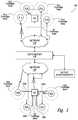
- FIG. 1illustrates an embodiment of a smart air pollution sensing and monitoring system 100 .
- System 100includes a data center 102 communicatively coupled to one or more sensor bases B (i.e., B 1 and B 2 in the illustrated embodiment) and one or more sensor nodes S (i.e., S 1 a -S 1 d and S 2 a -S 2 d in the illustrated embodiment).
- the illustrated embodimenthas two sensor bases B 1 -B 2 and eight sensor nodes S 1 a -S 1 d and S 2 a -S 2 d , but other embodiments can have more or less sensor bases than shown and more or less sensor nodes than shown.
- Data center 102includes various hardware elements, such as a communication interface, one or more servers each including at least one microprocessor, memory, and storage, and additional storage space that can include one or more databases, for instance to register information about the sensor bases B and sensor nodes S including their type, identity, location if fixed or current location if mobile, measurement history, etc.
- the communication interfacecommunicatively couples data center 102 to sensor nodes S 1 a -S 1 d and S 2 a -S 2 d and sensor bases B 1 and B 2 .
- Sensor nodes S 1 a -S 1 d and S 2 a -S 2 d and sensor bases B 1 -B 2can communicate with data center 102 by wire, wirelessly, or by some combination of wirelessly and wired.
- sensor nodes S 1 a and S 1 bcommunicate with data center 102 wirelessly via network 104
- sensor nodes S 1 c and S 1 dcommunicate with data center 102 by wire, also via a network 104
- sensor base B 1communicates with data center 102 by wire via network 104
- Sensor base B 2communicates with data center 102 wirelessly via network 104
- sensor nodes S 2 a and S 2 dcommunicate with data center 102 wirelessly and sensor nodes S 2 b and S 2 c communicate with data center 102 via wire, both via network 104
- Network 104can be the Internet, or can be a local area network (LAN), a wide area network (WAN), or some other type of network in different embodiments.
- Sensor nodes S 1 a -S 1 d and S 2 a -S 2 dare divided into sets that correspond to a sensor base: in the illustrated embodiment, sensor nodes S 1 a -S 1 d are grouped with sensor base B 1 and sensor nodes S 2 a -S 2 d are grouped with sensor base B 2 , so that in each grouping there is a many-to-one correspondence between sensor nodes and sensor bases. Other embodiments need not have this many-to-one correspondence, but can instead have a one-to-one correspondence between sensor nodes and sensor bases. And although in the illustrated embodiment sensor bases B 1 -B 2 are each grouped with four sensor nodes, in other embodiments each sensor base need not be grouped with the same number of sensor nodes.
- Each sensor node Shas a corresponding coverage area, which is an area in which an air sample gathered for analysis by the sensor node can be considered representative.
- Each sensor base Bsimilarly has a corresponding coverage area.
- sensor base B 1has a coverage area that overlaps with the coverage areas of sensor nodes S 1 a -S 1 d , so that an air sample gathered for analysis by sensor base B 1 can also be considered representative of conditions in the coverage areas of S 1 a -S 1 d .
- Sensor base B 2has a coverage area that does not overlap with the coverage areas of its set of sensor nodes S 2 a -S 2 d .
- a sampling manifold 106includes one or more sampling tubes 106 a - 106 d fluidly coupled to sensor base B 2 , with each sampling tube having one end at sensor base B 2 and the other extended into the coverage areas of sensor nodes S 2 a -S 2 d .
- “fluidly coupled”means coupled in such a way that fluid can flow one or both ways between two locations.
- sensor nodes S and sensor bases Boccupy fixed positions and are thus fixed relative to each other. But as discussed below, in some embodiments at least one of sensor bases B 1 and B 2 can be mobile; in these embodiments the positions of sensor bases B relative to sensor nodes S can change, so that each sensor node need not be permanently assigned to a particular sensor base. As a result, the exact composition of a group—that is, the numbers and identities of sensor bases and the numbers and identities of corresponding sensor nodes—can change over time. In some embodiments with mobile sensor bases the changes can be frequent enough that no particular group is recognizable.
- sensor nodes S 1 a -S 1 d and S 2 a -S 2 dare fixed on-site low-cost air quality monitoring sensors, which are substantially less expensive than sensor bases B and can be easily deployed on-site at various locations to form a high-density sensing network for on-site monitoring and provide big data analysis to deliver time-dense and spatially-dense usable air quality information to the public about airborne pollutants.
- Airborne pollutantscan include airborne chemicals and other airborne contaminants such as, without limitation, organic or inorganic chemicals such as volatile organic compounds (VOCs), NOx, SOx, O3; airborne particulate matter (PM), such as PM2.5 (i.e., particulate matter with 2.5 ⁇ m diameter) and PM10; compounds; heavy metal contaminants; airborne biological contaminants; etc.
- organic or inorganic chemicalssuch as volatile organic compounds (VOCs), NOx, SOx, O3
- VOCsvolatile organic compounds
- PMairborne particulate matter
- PM2.5i.e., particulate matter with 2.5 ⁇ m diameter
- PM10compounds
- compoundsheavy metal contaminants
- airborne biological contaminantsetc.
- the sensing data from sensor nodescan be wired or wirelessly uploaded to one or more servers for further data correction or analysis.
- sensor nodes Scan communicate directly with sensor bases B, instead of transmitting sensor node data directly to data center 102 , sensor nodes S can transmit sensor node data to data center 102 indirectly via a sensor base B.
- the low-cost sensorscan provide real time or more frequent on-site air quality monitoring results. The low-cost sensors used for sensing nodes S can suffer from sensitivity drift, which requires periodic baseline/sensitivity drift check and correction.
- Sensor bases B 1 -B 2serve as data references for their corresponding sensor nodes S.
- Sensor bases B 1 -B 2include analyzers to collect air samples and provide accurate, high-quality, and consistent measured results with high specificity on individual compound detection.
- Sensor bases B 1 -B 2measure air quality at specific locations and times using a high-performance air quality analyzer that can collect air samples and analyze them to provide concentrations of airborne pollutants.
- Pollutants measuredcan include, without limitation, organic or inorganic chemicals, such as volatile organic compounds (VOCs), NOx, SOx, O3; airborne particulate matter (PM) such as PM2.5 (i.e., particulate matter with 2.5 ⁇ m diameter) and PM10; compounds; heavy metal contaminants; airborne biological contaminants; etc.
- VOCsvolatile organic compounds
- PMairborne particulate matter
- PM2.5i.e., particulate matter with 2.5 ⁇ m diameter
- PM10compounds
- compoundsheavy metal contaminants; airborne biological contaminants; etc.
- Sensor bases B 1 -B 2can be fixed or mobile; when mobile, sensor bases B can include a position sensor, such as a GPS receiver, which they can use to report their current location to data center 102 .
- the sensor data for measurements carried out by sensor bases B 1 -B 2can be uploaded, by wire or wirelessly, to one or more servers in data center 102 .
- the sensor base datacan then be used as reference for data correction on sensor node results.
- Each sensor basecan also provide periodic reference data for on-site sensor node data correction, recalibration, or replacement.
- FIGS. 2A-2Btogether illustrate an embodiment of a process 200 by which measurements from the sensor bases B can be used to correct measurements from sensor nodes S.
- FIG. 2Ais a flowchart that will be discussed below n in the context of system 100 and the graphs of FIG. 2B .
- the process 200is carried out primarily by data center 102 .
- the processstarts at block 202 .
- a block 204data center 102 receives measurements from one or more sensor nodes with which it can communicate.
- the processchecks whether a current sensor base measurement is available for that sensor—that is, whether there is a sensor base measurement that is close in both time and space to the received sensor node measurements.
- the sensor base measurementwill essentially always be current. But in embodiments in which sensor bases B are not fixed relative to the sensor nodes—embodiments in which sensor bases B are mobile, for instance—the sensor base measurement may not be current if the sensor base has not recently been in the neighborhood of a sensor node from which a measurement has been received.
- sensor base Bcan collect and analyze air samples at or around the nodal coverage area of each sensor node S at a specified fixed frequency, but in other embodiments sensor base B can collect and analyze air samples at a special temporal period. In some embodiments special temporal periods include at random or when needed. In still other embodiments, if the data center determines that a specific sensor node is starting to drift faster than expected but still functions acceptably before replacement, the corresponding sensor base (fixed or mobile) that covers the sensor node can be adjusted to increase air sample monitoring frequency around that sensor node to provide more accurate data correction.
- the processproceeds to block 214 , where the sensor node data is reported.
- the sensor node datacan be reported as is—i.e., with whatever drift is present in the data.
- the data servercan utilize advanced artificial intelligence analysis to predict a possible correction based on the previous time-progressing drift/degradation of the same sensor node.
- the processmoves to block 208 , where it receives a current measurement from a sensor base or retrieves a current measurement from a database, and then proceeds to block 210 where it computes a drift for each received sensor node measurement.
- the driftcan be defined as the difference between the sensor node measurement and the sensor base measurement at or near a particular spatial location and a particular time, as shown in FIG. 2B .
- the sensor nodeshave data drift while continuing their air sensing (sensing concentration drooping down as shown in the figure). Without the data correction, the result from sensor node will provide the wrong monitoring result by misleading reduction of pollutant concentration.
- Driftscan be computed for measurements of total pollutant concentrations, for concentrations of individual compounds, or both. For instance, in a sensor node S that can sense five different pollutants, there can be a single drift for the total pollutant concentration, there can be five separate drifts, one for each pollutant, or there can be both total and individual drifts.
- the processproceeds to block 212 where the sensor node measurements are corrected. After the sensor node data correction using the sensor base result, the data drift issue of the low-cost sensor node can be more accurately obtained as shown in the lower graph (b) of FIG. 2B . With such a method, hundreds or thousands of sensor node data can be corrected and achieve reliable sensing network results.
- the processthen proceeds to block 214 , where the sensor node measurements are output to a user for further analysis or information. The process then returns to block 204 where it can receive further measurements from sensor nodes.
- the processcan also move to block 216 , were it checks whether the computed drift is greater than some threshold that indicates that a sensor node must be replaced or recalibrated. If at block 216 the drift of a particular sensor node is greater than some set threshold, the process moves on to block 218 , where it signals to a user that replacement or recalibration of the sensor node is required. After block 218 , the process returns to block 204 to receive measurements from the same or other sensor nodes. But if at block 216 the drift of a particular sensor node is less than some set threshold, the process returns to block 204 to receive measurements from the same or other sensor nodes.
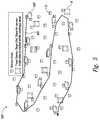
- FIG. 3illustrates an embodiment of positioning sensor bases and sensor nodes in an air quality monitoring system 300 .
- the sensor nodes S and sensor bases Bare fixed in space relative to each other, are stationary, and are deployed at various spatial locations.
- the coverage area of each sensor base Bencompasses one or more sensor nodes S, such that the coverage areas of each sensor base and its corresponding sensor nodes overlap.
- Each sensor basecan provide reference data for corresponding sensor nodes in the sensor base coverage area.
- FIG. 4illustrates another embodiment of positioning of sensor bases and sensor nodes in an air quality monitoring system 400 .
- the sensor nodes Sare deployed at various spatial locations.
- a mobile sensor base 402travels along a path 404 that brings it near enough to each sensor node S to allow it to collect a sample at or near the location where each sensor node is installed and analyze the collected samples.
- Using a mobile sensor base Ballows a small number of sensor bases to cover a larger number of sensor nodes S, so that spatially dense reference data can be obtained for data correction of each sensor node.
- FIG. 5illustrates another embodiment of positioning sensor bases and sensor nodes in an air quality monitoring system 500 .
- system 500a series of stationary sensor bases B and various sensor nodes S are deployed at various spatial locations.
- a mobile sensor base 502travels along a path 504 that allows it to collect samples at or near the location where each sensor base B and each sensor node S is installed and analyze the collected samples. By doing so, mobile sensor base 502 serves as a backup to the multiple fixed sensor bases B and also collects and provides reference data for data correction of each sensor node.
- some sensor nodes Smay be installed at locations where they are not covered by any fixed sensor bases B.
- the mobile sensor basecan be used to provide the reference data for drift correction needed on those sensor nodes.
- FIG. 6illustrates another embodiment of positioning sensor bases and sensor nodes in an air quality monitoring system 600 .
- FIG. 6illustrates low-cost sensor nodes S deployed in a city, primarily outside of a building, in the streets, and on the sidewalks, to form a sensing network to monitor urban air quality.
- Mobile sensor bases 602which can for instance be sensor bases installed on vehicles for mobile monitoring, can drive through city streets near known locations of sensor nodes S to collect reference data when the sensor base moves to corresponding nearby sensing nodes.
- FIG. 7illustrates another embodiment of positioning sensor bases and sensor nodes in an air quality monitoring system 700 .
- FIG. 7illustrates low-cost sensor nodes S deployed inside a building 704 with a high-performance analyzer serving as sensor base B.
- Manifold tubes or pipes 702are extended from sensor base B to different floors and locations for air quality monitoring in the interior of the building.
- the sensor base data for each floor/locationcan be used to correct the sensor node data.
- FIG. 8illustrates another embodiment of positioning sensor bases and sensor nodes in an air quality monitoring system 800 .
- Sensor nodes Sare installed at various locations inside and outside buildings in a city (although the embodiment is not limited to a city).
- Stationary sensor bases Bcan be, but aren't necessarily, installed inside or outside the building, with or without manifold sampling connected to air of interest from the stationary base station.
- Additional mobile sensor bases 802can be used to transport the high-performance air quality analyzers to corresponding sensor node locations, which can cover sensor nodes positioned at locations the stationary sensor bases cannot reach for monitoring.
Landscapes
- Chemical & Material Sciences (AREA)
- Engineering & Computer Science (AREA)
- Health & Medical Sciences (AREA)
- Life Sciences & Earth Sciences (AREA)
- General Health & Medical Sciences (AREA)
- Physics & Mathematics (AREA)
- General Physics & Mathematics (AREA)
- Immunology (AREA)
- Pathology (AREA)
- Biochemistry (AREA)
- Analytical Chemistry (AREA)
- Business, Economics & Management (AREA)
- Medicinal Chemistry (AREA)
- Food Science & Technology (AREA)
- Combustion & Propulsion (AREA)
- Tourism & Hospitality (AREA)
- Medical Informatics (AREA)
- Human Resources & Organizations (AREA)
- Signal Processing (AREA)
- Theoretical Computer Science (AREA)
- Computer Networks & Wireless Communication (AREA)
- Strategic Management (AREA)
- Development Economics (AREA)
- Primary Health Care (AREA)
- Marketing (AREA)
- General Business, Economics & Management (AREA)
- Economics (AREA)
- Computing Systems (AREA)
- Educational Administration (AREA)
- Biomedical Technology (AREA)
- Molecular Biology (AREA)
- Sampling And Sample Adjustment (AREA)
- Arrangements For Transmission Of Measured Signals (AREA)
- Selective Calling Equipment (AREA)
- Indication And Recording Devices For Special Purposes And Tariff Metering Devices (AREA)
- Measuring Pulse, Heart Rate, Blood Pressure Or Blood Flow (AREA)
Abstract
Description
Claims (32)
Priority Applications (14)
| Application Number | Priority Date | Filing Date | Title |
|---|---|---|---|
| US15/810,409US11047839B2 (en) | 2016-11-16 | 2017-11-13 | Smart sensing network |
| CN202210692787.7ACN115102989B (en) | 2016-11-16 | 2017-11-14 | Intelligent sensing network |
| PCT/US2017/061605WO2018093792A1 (en) | 2016-11-16 | 2017-11-14 | Smart sensing network |
| KR1020227036648AKR102772166B1 (en) | 2016-11-16 | 2017-11-14 | Smart sensing network |
| KR1020197015512AKR102458890B1 (en) | 2016-11-16 | 2017-11-14 | smart sensing network |
| JP2019547223AJP2019536188A (en) | 2016-11-16 | 2017-11-14 | Smart detection network |
| EP17871447.3AEP3542521B1 (en) | 2016-11-16 | 2017-11-14 | Smart sensing network |
| CN201780075261.1ACN110121875B (en) | 2016-11-16 | 2017-11-14 | Intelligent sensing network |
| TW109111005ATWI764120B (en) | 2016-11-16 | 2017-11-16 | Smart sensing network and process of using the same |
| TW106139699ATWI713801B (en) | 2016-11-16 | 2017-11-16 | Smart sensing network and process of using the same |
| TW110123101ATWI818273B (en) | 2016-11-16 | 2017-11-16 | Smart sensing network and process of using the same |
| US17/352,966US11788997B2 (en) | 2016-11-16 | 2021-06-21 | Smart sensing network |
| US18/487,337US12276646B2 (en) | 2016-11-16 | 2023-10-16 | Smart sensing network |
| JP2024002280AJP2024056685A (en) | 2016-11-16 | 2024-01-11 | Smart Detection Network |
Applications Claiming Priority (2)
| Application Number | Priority Date | Filing Date | Title |
|---|---|---|---|
| US201662423033P | 2016-11-16 | 2016-11-16 | |
| US15/810,409US11047839B2 (en) | 2016-11-16 | 2017-11-13 | Smart sensing network |
Related Child Applications (1)
| Application Number | Title | Priority Date | Filing Date |
|---|---|---|---|
| US17/352,966ContinuationUS11788997B2 (en) | 2016-11-16 | 2021-06-21 | Smart sensing network |
Publications (2)
| Publication Number | Publication Date |
|---|---|
| US20180136180A1 US20180136180A1 (en) | 2018-05-17 |
| US11047839B2true US11047839B2 (en) | 2021-06-29 |
Family
ID=62108402
Family Applications (3)
| Application Number | Title | Priority Date | Filing Date |
|---|---|---|---|
| US15/810,409Active2039-04-02US11047839B2 (en) | 2016-11-16 | 2017-11-13 | Smart sensing network |
| US17/352,966ActiveUS11788997B2 (en) | 2016-11-16 | 2021-06-21 | Smart sensing network |
| US18/487,337ActiveUS12276646B2 (en) | 2016-11-16 | 2023-10-16 | Smart sensing network |
Family Applications After (2)
| Application Number | Title | Priority Date | Filing Date |
|---|---|---|---|
| US17/352,966ActiveUS11788997B2 (en) | 2016-11-16 | 2021-06-21 | Smart sensing network |
| US18/487,337ActiveUS12276646B2 (en) | 2016-11-16 | 2023-10-16 | Smart sensing network |
Country Status (7)
| Country | Link |
|---|---|
| US (3) | US11047839B2 (en) |
| EP (1) | EP3542521B1 (en) |
| JP (2) | JP2019536188A (en) |
| KR (2) | KR102458890B1 (en) |
| CN (2) | CN115102989B (en) |
| TW (3) | TWI713801B (en) |
| WO (1) | WO2018093792A1 (en) |
Cited By (1)
| Publication number | Priority date | Publication date | Assignee | Title |
|---|---|---|---|---|
| US20210215654A1 (en)* | 2020-01-08 | 2021-07-15 | Richard M. COSTANZO | System and Method for Multidimensional Gas Sensing and Localization |
Families Citing this family (12)
| Publication number | Priority date | Publication date | Assignee | Title |
|---|---|---|---|---|
| US11047839B2 (en) | 2016-11-16 | 2021-06-29 | TricornTech Taiwan | Smart sensing network |
| CN107219157A (en)* | 2017-07-29 | 2017-09-29 | 山东诺方电子科技有限公司 | It is a kind of to carry out atmosphere particle monitoring system using public vehicles |
| CN108834151A (en)* | 2018-05-30 | 2018-11-16 | 西安理工大学 | A coverage method of wireless sensor network in marine environment |
| CN109242062B (en)* | 2018-09-06 | 2021-09-03 | 重庆云力网通科技有限公司 | Method for realizing social credit investigation system |
| FR3090881B1 (en)* | 2018-12-19 | 2023-10-20 | Elichens | Method for calibrating a gas sensor |
| WO2020237112A1 (en)* | 2019-05-22 | 2020-11-26 | Molex, Llc | Systems and methods for placing networked sensors within a facility for fugitive emissions monitoring |
| CN110312225B (en)* | 2019-07-30 | 2022-06-03 | 平顶山学院 | Wireless sensor hardware device |
| JP7202989B2 (en)* | 2019-08-23 | 2023-01-12 | 東京瓦斯株式会社 | Sensor maintenance system, information processing device, and program |
| CN111239338A (en)* | 2020-01-19 | 2020-06-05 | 徐州工业职业技术学院 | Open air quality monitoring system |
| KR102377148B1 (en)* | 2020-09-03 | 2022-03-23 | (주)누리플렉스 | Smart quarantine grid system and method thereof |
| DE102021105014A1 (en) | 2021-03-02 | 2022-09-08 | Dräger Safety AG & Co. KGaA | Method for evaluating data from at least one mobile and one stationary gas measuring device and system for monitoring at least one gas concentration |
| CN115358432B (en) | 2022-10-14 | 2023-02-07 | 成都秦川物联网科技股份有限公司 | Gas meter metering fault determination method for intelligent gas and Internet of things system |
Citations (14)
| Publication number | Priority date | Publication date | Assignee | Title |
|---|---|---|---|---|
| US6701772B2 (en)* | 2000-12-22 | 2004-03-09 | Honeywell International Inc. | Chemical or biological attack detection and mitigation system |
| US7360461B2 (en)* | 2004-09-23 | 2008-04-22 | Aircuity, Inc. | Air monitoring system having tubing with an electrically conductive inner surface for transporting air samples |
| US8190367B2 (en)* | 2006-02-21 | 2012-05-29 | Nir Bassa | System and method for assessing and reducing air pollution by regulating airflow ventilation |
| TW201229441A (en) | 2010-11-01 | 2012-07-16 | Koninkl Philips Electronics Nv | A method of calibrating an air sensor field of the invention |
| US20130074575A1 (en) | 2011-09-16 | 2013-03-28 | Siemens Aktiengesellschaft | Method and test device for field calibration of a gas detector |
| TW201337262A (en) | 2012-03-01 | 2013-09-16 | Univ Nat Taipei Technology | Wireless air quality monitoring system and method thereof |
| US20130278427A1 (en) | 2012-04-22 | 2013-10-24 | Michael Setton | Method and system for visually reporting a local environmental condition |
| US8717161B1 (en)* | 2011-11-21 | 2014-05-06 | Crook W. Gary | Lockout for hydrogen sulfide monitoring system |
| US20140238107A1 (en) | 2013-02-28 | 2014-08-28 | TricornTech Taiwan | Real-time on-site gas analysis network for ambient air monitoring and active control and response |
| US20140278186A1 (en)* | 2013-03-13 | 2014-09-18 | Aclima Inc. | Calibration method for distributed sensor system |
| US20150153299A1 (en)* | 2013-12-02 | 2015-06-04 | TricornTech Taiwan | Real-time air monitoring with multiple sensing modes |
| US20150253300A1 (en) | 2012-09-20 | 2015-09-10 | C.R.D. Centro Ricerche Ducati Trento S.R.L. | System and method for monitoring atmospheric pollution |
| US20150325100A1 (en) | 2001-10-10 | 2015-11-12 | Google Inc. | Remote sensors for detecting alert conditions and notifying a central station |
| US20160123947A1 (en) | 2002-03-15 | 2016-05-05 | Nanomix, Inc. | Ammonia Nanosensors, and Environmental Control System |
Family Cites Families (19)
| Publication number | Priority date | Publication date | Assignee | Title |
|---|---|---|---|---|
| US5832411A (en)* | 1997-02-06 | 1998-11-03 | Raytheon Company | Automated network of sensor units for real-time monitoring of compounds in a fluid over a distributed area |
| JPH11142128A (en)* | 1997-11-07 | 1999-05-28 | Earthnics Corp | Radiation thickness-gauge |
| US20040105533A1 (en)* | 1998-08-07 | 2004-06-03 | Input/Output, Inc. | Single station wireless seismic data acquisition method and apparatus |
| US6334059B1 (en)* | 1999-01-08 | 2001-12-25 | Trueposition, Inc. | Modified transmission method for improving accuracy for e-911 calls |
| JP2001289811A (en)* | 2000-02-03 | 2001-10-19 | Nippon Koden Corp | Gas sensor and gas sensor system |
| JP2004108857A (en)* | 2002-09-17 | 2004-04-08 | Horiba Ltd | Atmospheric pollution monitoring system |
| US7835043B2 (en) | 2006-09-06 | 2010-11-16 | Hewlett-Packard Development Company, L.P. | Imaging device and calibration method therefor |
| JP5476632B2 (en)* | 2010-05-11 | 2014-04-23 | 公立大学法人大阪府立大学 | Quartz Crystal Coating Liquid, Gas Detection Element, Ethylene Detection Element, and Gas Detection Element Manufacturing Method |
| CN202471958U (en)* | 2012-03-19 | 2012-10-03 | 河北工业大学 | Quick locating system for sudden disaster accidents |
| WO2014164547A1 (en)* | 2013-03-13 | 2014-10-09 | Aclima Inc. | Distributed sensor system with remote sensor nodes and centralized data processing |
| US9297748B2 (en)* | 2013-03-13 | 2016-03-29 | Aclima Inc. | Distributed sensor system with remote sensor nodes and centralized data processing |
| RU2015156636A (en)* | 2013-06-11 | 2017-07-20 | Филипс Лайтинг Холдинг Б.В. | SENSOR CALIBRATION METHOD |
| JP6375629B2 (en)* | 2014-01-28 | 2018-08-22 | 富士通株式会社 | Gas sensor and manufacturing method thereof |
| CN104251808A (en)* | 2014-09-16 | 2014-12-31 | 苏州弗莱希智能科技有限公司 | High-accuracy PM2.5 detector |
| JP6409567B2 (en)* | 2014-12-25 | 2018-10-24 | 株式会社デンソー | Gas sensor |
| US9719972B2 (en)* | 2015-03-31 | 2017-08-01 | International Business Machines Corporation | System and method for air-pollutant source-localization using parked motor vehicles |
| CN204649241U (en)* | 2015-06-02 | 2015-09-16 | 深圳市万联智慧电子有限公司 | PM2.5 monitor and environmental monitoring system thereof |
| CN106053724B (en)* | 2016-05-25 | 2018-01-02 | 深圳市欧瑞博电子有限公司 | Gas sensor precision compensation method and device based on cloud computing |
| US11047839B2 (en) | 2016-11-16 | 2021-06-29 | TricornTech Taiwan | Smart sensing network |
- 2017
- 2017-11-13USUS15/810,409patent/US11047839B2/enactiveActive
- 2017-11-14KRKR1020197015512Apatent/KR102458890B1/enactiveActive
- 2017-11-14WOPCT/US2017/061605patent/WO2018093792A1/ennot_activeCeased
- 2017-11-14CNCN202210692787.7Apatent/CN115102989B/enactiveActive
- 2017-11-14JPJP2019547223Apatent/JP2019536188A/enactivePending
- 2017-11-14EPEP17871447.3Apatent/EP3542521B1/enactiveActive
- 2017-11-14CNCN201780075261.1Apatent/CN110121875B/enactiveActive
- 2017-11-14KRKR1020227036648Apatent/KR102772166B1/enactiveActive
- 2017-11-16TWTW106139699Apatent/TWI713801B/enactive
- 2017-11-16TWTW110123101Apatent/TWI818273B/enactive
- 2017-11-16TWTW109111005Apatent/TWI764120B/enactive
- 2021
- 2021-06-21USUS17/352,966patent/US11788997B2/enactiveActive
- 2023
- 2023-10-16USUS18/487,337patent/US12276646B2/enactiveActive
- 2024
- 2024-01-11JPJP2024002280Apatent/JP2024056685A/enactivePending
Patent Citations (15)
| Publication number | Priority date | Publication date | Assignee | Title |
|---|---|---|---|---|
| US6701772B2 (en)* | 2000-12-22 | 2004-03-09 | Honeywell International Inc. | Chemical or biological attack detection and mitigation system |
| US20150325100A1 (en) | 2001-10-10 | 2015-11-12 | Google Inc. | Remote sensors for detecting alert conditions and notifying a central station |
| US20160123947A1 (en) | 2002-03-15 | 2016-05-05 | Nanomix, Inc. | Ammonia Nanosensors, and Environmental Control System |
| US7360461B2 (en)* | 2004-09-23 | 2008-04-22 | Aircuity, Inc. | Air monitoring system having tubing with an electrically conductive inner surface for transporting air samples |
| US8190367B2 (en)* | 2006-02-21 | 2012-05-29 | Nir Bassa | System and method for assessing and reducing air pollution by regulating airflow ventilation |
| TW201229441A (en) | 2010-11-01 | 2012-07-16 | Koninkl Philips Electronics Nv | A method of calibrating an air sensor field of the invention |
| US20130074575A1 (en) | 2011-09-16 | 2013-03-28 | Siemens Aktiengesellschaft | Method and test device for field calibration of a gas detector |
| US8717161B1 (en)* | 2011-11-21 | 2014-05-06 | Crook W. Gary | Lockout for hydrogen sulfide monitoring system |
| TW201337262A (en) | 2012-03-01 | 2013-09-16 | Univ Nat Taipei Technology | Wireless air quality monitoring system and method thereof |
| US20130278427A1 (en) | 2012-04-22 | 2013-10-24 | Michael Setton | Method and system for visually reporting a local environmental condition |
| US20150253300A1 (en) | 2012-09-20 | 2015-09-10 | C.R.D. Centro Ricerche Ducati Trento S.R.L. | System and method for monitoring atmospheric pollution |
| TW201502508A (en) | 2013-02-28 | 2015-01-16 | TricornTech Taiwan | Instant on-site gas analysis network for ambient air monitoring and active control and response |
| US20140238107A1 (en) | 2013-02-28 | 2014-08-28 | TricornTech Taiwan | Real-time on-site gas analysis network for ambient air monitoring and active control and response |
| US20140278186A1 (en)* | 2013-03-13 | 2014-09-18 | Aclima Inc. | Calibration method for distributed sensor system |
| US20150153299A1 (en)* | 2013-12-02 | 2015-06-04 | TricornTech Taiwan | Real-time air monitoring with multiple sensing modes |
Non-Patent Citations (9)
| Title |
|---|
| Hasenfratz et al., "On-the-fly Calibration of Low-cost Gas Sensors", Computer Engineering and Networks Laboratory, ETH Zurich, Switzerland, Oct. 26, 2015, 16 pages. |
| International Preliminary Report on Patentability received for PCT Patent Application No. PCT/US2017/061605, dated May 31, 2019, 10 pages. |
| International Search Report and Written Opinion received for PCT Patent Application No. PCT/US2017/061605, dated Feb. 9, 2018, 16 pages. |
| Office Action received for European Patent Application No. 17871447.3, dated Apr. 30, 2021, 3 pages. |
| Office Action received for Taiwanese Patent Application No. 106139699, dated Jul. 9, 2019, 7 pages (3 pages of English Translation and 4 pages of Office Action). |
| Office Action received for Taiwanese Patent Application No. 106139699, dated May 20, 2020, 8 pages (4 pages of English Translation and 4 pages of Office Action). |
| Office Action received for Taiwanese Patent Application No. 106139699, dated Oct. 18, 2018, 15 pages (6 pages of English Translation and 9 pages of Office Action). |
| Office Action received for Taiwanese Patent Application No. 109111005, dated Apr. 19, 2021, 11 pages (5 pages of English Translation and 6 pages of Office Action). |
| Supplementary European Search Report and Search Opinion received for EP Application No. 17871447.3, dated Sep. 7, 2020, 6 pages. |
Cited By (1)
| Publication number | Priority date | Publication date | Assignee | Title |
|---|---|---|---|---|
| US20210215654A1 (en)* | 2020-01-08 | 2021-07-15 | Richard M. COSTANZO | System and Method for Multidimensional Gas Sensing and Localization |
Also Published As
| Publication number | Publication date |
|---|---|
| CN110121875A (en) | 2019-08-13 |
| EP3542521A4 (en) | 2020-10-07 |
| TW202044177A (en) | 2020-12-01 |
| CN110121875B (en) | 2022-06-24 |
| KR102458890B1 (en) | 2022-10-24 |
| US20240036017A1 (en) | 2024-02-01 |
| CN115102989B (en) | 2024-03-12 |
| TWI818273B (en) | 2023-10-11 |
| US11788997B2 (en) | 2023-10-17 |
| TW202207142A (en) | 2022-02-16 |
| TW201826205A (en) | 2018-07-16 |
| KR102772166B1 (en) | 2025-02-21 |
| JP2019536188A (en) | 2019-12-12 |
| TWI713801B (en) | 2020-12-21 |
| TWI764120B (en) | 2022-05-11 |
| KR20190073519A (en) | 2019-06-26 |
| WO2018093792A1 (en) | 2018-05-24 |
| US20180136180A1 (en) | 2018-05-17 |
| JP2024056685A (en) | 2024-04-23 |
| KR20220148932A (en) | 2022-11-07 |
| EP3542521A1 (en) | 2019-09-25 |
| US12276646B2 (en) | 2025-04-15 |
| EP3542521B1 (en) | 2023-08-23 |
| CN115102989A (en) | 2022-09-23 |
| US20210311005A1 (en) | 2021-10-07 |
Similar Documents
| Publication | Publication Date | Title |
|---|---|---|
| US11788997B2 (en) | Smart sensing network | |
| Saukh et al. | Reducing multi-hop calibration errors in large-scale mobile sensor networks | |
| KR102786679B1 (en) | Hyper-local mapping of environmental conditions | |
| US8949037B2 (en) | Method and system for detecting and monitoring emissions | |
| WO2008086606A1 (en) | Method and system for detecting and monitoring emissions | |
| KR20140058727A (en) | Environment monitoring system | |
| KR20150042034A (en) | Mobile sensor based air quality measurement method | |
| Listyarini et al. | The Air Quality Monitoring Tool Based on Internet of Things to Monitor Pollution Emissions Continuously | |
| KR102158932B1 (en) | Concentration Compension System of a Particulate Matter Analyzer and Method Thereof | |
| Frederickson et al. | Are dense networks of low-cost nodes better at monitoring air pollution? A case study in Staffordshire | |
| Imran et al. | Cost Effective Air Quality Monitoring System Based on Xbee Wireless Sensor Networks | |
| Borghi | Assessment of portable and miniaturized sensors for the monitoring of human exposure to air pollutants | |
| Yadav et al. | Air Pollution Monitoring using GIS and Wireless Networking for Air Quality Management | |
| Task Order et al. | DETAILED MONITORING PROTOCOL |
Legal Events
| Date | Code | Title | Description |
|---|---|---|---|
| FEPP | Fee payment procedure | Free format text:ENTITY STATUS SET TO UNDISCOUNTED (ORIGINAL EVENT CODE: BIG.); ENTITY STATUS OF PATENT OWNER: SMALL ENTITY | |
| FEPP | Fee payment procedure | Free format text:ENTITY STATUS SET TO SMALL (ORIGINAL EVENT CODE: SMAL); ENTITY STATUS OF PATENT OWNER: SMALL ENTITY | |
| STPP | Information on status: patent application and granting procedure in general | Free format text:DOCKETED NEW CASE - READY FOR EXAMINATION | |
| AS | Assignment | Owner name:TRICORNTECH TAIWAN, TAIWAN Free format text:ASSIGNMENT OF ASSIGNORS INTEREST;ASSIGNOR:CHOU, TSUNG-KUAN A.;REEL/FRAME:049201/0068 Effective date:20181008 | |
| STPP | Information on status: patent application and granting procedure in general | Free format text:NON FINAL ACTION MAILED | |
| STPP | Information on status: patent application and granting procedure in general | Free format text:NON FINAL ACTION MAILED | |
| STPP | Information on status: patent application and granting procedure in general | Free format text:RESPONSE TO NON-FINAL OFFICE ACTION ENTERED AND FORWARDED TO EXAMINER | |
| STPP | Information on status: patent application and granting procedure in general | Free format text:FINAL REJECTION MAILED | |
| STPP | Information on status: patent application and granting procedure in general | Free format text:NOTICE OF ALLOWANCE MAILED -- APPLICATION RECEIVED IN OFFICE OF PUBLICATIONS | |
| STPP | Information on status: patent application and granting procedure in general | Free format text:AWAITING TC RESP., ISSUE FEE NOT PAID | |
| STPP | Information on status: patent application and granting procedure in general | Free format text:PUBLICATIONS -- ISSUE FEE PAYMENT RECEIVED | |
| STPP | Information on status: patent application and granting procedure in general | Free format text:PUBLICATIONS -- ISSUE FEE PAYMENT VERIFIED | |
| STCF | Information on status: patent grant | Free format text:PATENTED CASE | |
| AS | Assignment | Owner name:TRICORNTECH CORPORATION, TAIWAN Free format text:CHANGE OF NAME;ASSIGNOR:TRICORNTECH TAIWAN CORPORATION;REEL/FRAME:068404/0415 Effective date:20230613 | |
| MAFP | Maintenance fee payment | Free format text:PAYMENT OF MAINTENANCE FEE, 4TH YR, SMALL ENTITY (ORIGINAL EVENT CODE: M2551); ENTITY STATUS OF PATENT OWNER: SMALL ENTITY Year of fee payment:4 |