US11047487B2 - Method for manufacturing a block forged valve body with a fully encapsulated seat ring - Google Patents
Method for manufacturing a block forged valve body with a fully encapsulated seat ringDownload PDFInfo
- Publication number
- US11047487B2 US11047487B2US16/458,704US201916458704AUS11047487B2US 11047487 B2US11047487 B2US 11047487B2US 201916458704 AUS201916458704 AUS 201916458704AUS 11047487 B2US11047487 B2US 11047487B2
- Authority
- US
- United States
- Prior art keywords
- pair
- valve
- axis
- annular
- chamber
- Prior art date
- Legal status (The legal status is an assumption and is not a legal conclusion. Google has not performed a legal analysis and makes no representation as to the accuracy of the status listed.)
- Active
Links
- 238000000034methodMethods0.000titleclaimsabstractdescription30
- 238000004519manufacturing processMethods0.000titleclaimsabstractdescription11
- 238000003754machiningMethods0.000claimsdescription30
- 238000005242forgingMethods0.000claimsdescription9
- 238000007789sealingMethods0.000claimsdescription6
- 238000003466weldingMethods0.000claimsdescription5
- 230000008901benefitEffects0.000description3
- 238000005266castingMethods0.000description3
- 238000003801millingMethods0.000description3
- 238000011144upstream manufacturingMethods0.000description3
- 230000032798delaminationEffects0.000description2
- 238000005553drillingMethods0.000description2
- 238000005552hardfacingMethods0.000description2
- 238000007514turningMethods0.000description2
- 229910001347StelliteInorganic materials0.000description1
- 230000015572biosynthetic processEffects0.000description1
- AHICWQREWHDHHF-UHFFFAOYSA-Nchromium;cobalt;iron;manganese;methane;molybdenum;nickel;silicon;tungstenChemical compoundC.[Si].[Cr].[Mn].[Fe].[Co].[Ni].[Mo].[W]AHICWQREWHDHHF-UHFFFAOYSA-N0.000description1
- 230000006835compressionEffects0.000description1
- 238000007906compressionMethods0.000description1
- 230000008878couplingEffects0.000description1
- 238000010168coupling processMethods0.000description1
- 238000005859coupling reactionMethods0.000description1
- 238000005538encapsulationMethods0.000description1
- 230000007246mechanismEffects0.000description1
- 239000002994raw materialSubstances0.000description1
- 230000000630rising effectEffects0.000description1
- 238000007493shaping processMethods0.000description1
Images


Classifications
- B—PERFORMING OPERATIONS; TRANSPORTING
- B23—MACHINE TOOLS; METAL-WORKING NOT OTHERWISE PROVIDED FOR
- B23P—METAL-WORKING NOT OTHERWISE PROVIDED FOR; COMBINED OPERATIONS; UNIVERSAL MACHINE TOOLS
- B23P15/00—Making specific metal objects by operations not covered by a single other subclass or a group in this subclass
- B23P15/001—Making specific metal objects by operations not covered by a single other subclass or a group in this subclass valves or valve housings
- B—PERFORMING OPERATIONS; TRANSPORTING
- B21—MECHANICAL METAL-WORKING WITHOUT ESSENTIALLY REMOVING MATERIAL; PUNCHING METAL
- B21K—MAKING FORGED OR PRESSED METAL PRODUCTS, e.g. HORSE-SHOES, RIVETS, BOLTS OR WHEELS
- B21K1/00—Making machine elements
- B21K1/20—Making machine elements valve parts
- B21K1/24—Making machine elements valve parts valve bodies; valve seats
- F—MECHANICAL ENGINEERING; LIGHTING; HEATING; WEAPONS; BLASTING
- F16—ENGINEERING ELEMENTS AND UNITS; GENERAL MEASURES FOR PRODUCING AND MAINTAINING EFFECTIVE FUNCTIONING OF MACHINES OR INSTALLATIONS; THERMAL INSULATION IN GENERAL
- F16K—VALVES; TAPS; COCKS; ACTUATING-FLOATS; DEVICES FOR VENTING OR AERATING
- F16K25/00—Details relating to contact between valve members and seats
- F16K25/005—Particular materials for seats or closure elements
- F—MECHANICAL ENGINEERING; LIGHTING; HEATING; WEAPONS; BLASTING
- F16—ENGINEERING ELEMENTS AND UNITS; GENERAL MEASURES FOR PRODUCING AND MAINTAINING EFFECTIVE FUNCTIONING OF MACHINES OR INSTALLATIONS; THERMAL INSULATION IN GENERAL
- F16K—VALVES; TAPS; COCKS; ACTUATING-FLOATS; DEVICES FOR VENTING OR AERATING
- F16K27/00—Construction of housing; Use of materials therefor
- F16K27/04—Construction of housing; Use of materials therefor of sliding valves
- F16K27/044—Construction of housing; Use of materials therefor of sliding valves slide valves with flat obturating members
- F—MECHANICAL ENGINEERING; LIGHTING; HEATING; WEAPONS; BLASTING
- F16—ENGINEERING ELEMENTS AND UNITS; GENERAL MEASURES FOR PRODUCING AND MAINTAINING EFFECTIVE FUNCTIONING OF MACHINES OR INSTALLATIONS; THERMAL INSULATION IN GENERAL
- F16K—VALVES; TAPS; COCKS; ACTUATING-FLOATS; DEVICES FOR VENTING OR AERATING
- F16K3/00—Gate valves or sliding valves, i.e. cut-off apparatus with closing members having a sliding movement along the seat for opening and closing
- F16K3/02—Gate valves or sliding valves, i.e. cut-off apparatus with closing members having a sliding movement along the seat for opening and closing with flat sealing faces; Packings therefor
- F16K3/04—Gate valves or sliding valves, i.e. cut-off apparatus with closing members having a sliding movement along the seat for opening and closing with flat sealing faces; Packings therefor with pivoted closure members
- F16K3/10—Gate valves or sliding valves, i.e. cut-off apparatus with closing members having a sliding movement along the seat for opening and closing with flat sealing faces; Packings therefor with pivoted closure members with special arrangements for separating the sealing faces or for pressing them together
- F—MECHANICAL ENGINEERING; LIGHTING; HEATING; WEAPONS; BLASTING
- F16—ENGINEERING ELEMENTS AND UNITS; GENERAL MEASURES FOR PRODUCING AND MAINTAINING EFFECTIVE FUNCTIONING OF MACHINES OR INSTALLATIONS; THERMAL INSULATION IN GENERAL
- F16K—VALVES; TAPS; COCKS; ACTUATING-FLOATS; DEVICES FOR VENTING OR AERATING
- F16K3/00—Gate valves or sliding valves, i.e. cut-off apparatus with closing members having a sliding movement along the seat for opening and closing
- F16K3/02—Gate valves or sliding valves, i.e. cut-off apparatus with closing members having a sliding movement along the seat for opening and closing with flat sealing faces; Packings therefor
- F16K3/16—Gate valves or sliding valves, i.e. cut-off apparatus with closing members having a sliding movement along the seat for opening and closing with flat sealing faces; Packings therefor with special arrangements for separating the sealing faces or for pressing them together
- F16K3/18—Gate valves or sliding valves, i.e. cut-off apparatus with closing members having a sliding movement along the seat for opening and closing with flat sealing faces; Packings therefor with special arrangements for separating the sealing faces or for pressing them together by movement of the closure members
- F—MECHANICAL ENGINEERING; LIGHTING; HEATING; WEAPONS; BLASTING
- F16—ENGINEERING ELEMENTS AND UNITS; GENERAL MEASURES FOR PRODUCING AND MAINTAINING EFFECTIVE FUNCTIONING OF MACHINES OR INSTALLATIONS; THERMAL INSULATION IN GENERAL
- F16K—VALVES; TAPS; COCKS; ACTUATING-FLOATS; DEVICES FOR VENTING OR AERATING
- F16K3/00—Gate valves or sliding valves, i.e. cut-off apparatus with closing members having a sliding movement along the seat for opening and closing
- F16K3/30—Details
- F16K3/314—Forms or constructions of slides; Attachment of the slide to the spindle
Definitions
- the present disclosurerelates generally to a valve body, and in particular to a method of manufacturing a block forged valve body having a fully encapsulated seat ring, and to the block forged valve body with a fully encapsulated seat ring and the method for the use thereof.
- Gate valvestypically include a valve body having a flow passageway and gates that slide transversely to open or close the flow passageway.
- a pair of valve seatsis positioned in the flow passageway to interface with the gates as they move between open and closed positions.
- the valve seatsare not fully encapsulated around the circumferential periphery thereof, which leads to the valve seat being susceptible to deflection or deformation. Deformation of the valve seat may lead to delamination of the seat ring, for example of a hard seal surface applied thereto, which may contaminate and/or damage the media passing through the valve and equipment located downstream of the valve, or lead to less than optimum sealing of the valve.
- the valve bodymay be made from a casting or die forging, which allows for the formation and definition of various features. Casting and die forging require expensive and unique molds and dies, which are not easily reconfigured. As such, the casting and die forging processes do not lend themselves to easily reconfiguring the shape and function of the valve body, for example if a larger gate and/or through opening is required.
- valve bodymay be configured by connecting a plurality of separate parts, for example coupling top, middle and bottom portions, or side portions, with mechanical fasteners.
- These types of valve bodiesrequire additional fasteners and sealing interfaces, and are more susceptible to leakage, for example over time, than a one-piece valve body.
- one embodiment of a method of manufacturing a valve bodyincludes block forging a one-piece body having opposite ends, opposite sides, a top and a bottom.
- the methodfurther includes machining a through hole, which has a first minimum diameter and extends along a first axis, between the opposite ends.
- the through holedefines a flow passageway.
- the methodalso includes machining a chamber, which has a second minimum diameter and extends from the top along a second axis orthogonal to the first axis.
- the chamberincludes a bottom defined by a floor, which separates the chamber from the through hole.
- the methodfurther includes machining a passageway through the floor between the chamber and the through hole and thereby defining a pair of semi-circular shelf portions overlying the through hole, and machining an annular shoulder, which has a third diameter and extends along the first axis under each of the shelf portions.
- Each of the annular shouldershas a first depth defined under the shelf portion along the first axis, and are coaxial with the through opening.
- the methodfurther includes inserting a valve seat in each of the annular shoulders, wherein each of the valve seats has a circumferential surface having a second depth. The second depth is between 125 and 135% of the first depth. An entirety of the first depth is in contact with the circumferential surface of a corresponding valve seat.
- the valve seatseach have a front side facing each other and a backside facing away from each other.
- a method of manufacturing a valvefurther includes inserting a valve stem in the chamber along the second axis, wherein a pair of spring loaded discs is coupled to the end of the valve stem.
- the discsare moveable along the second axis from a closed position, wherein the discs are disposed in the through hole in engagement with the valve seats, to an open position, wherein the discs are disposed at least partially in the chamber such that the through channel is not blocked by the discs.
- one embodiment of a valve bodyin another aspect, includes a one piece block forged body having opposite ends, opposite sides, a top and a bottom.
- the block forged bodyfurther includes a through hole, which has a first minimum diameter and extends along a first axis between the opposite ends.
- the through holedefines a flow passageway.
- a chamberhas a second minimum diameter and extends from the top along a second axis orthogonal to the first axis.
- the chamberincludes a bottom defined by a floor separating the chamber from the through hole.
- a passagewayextends through the floor between the chamber and the through hole.
- the floorcomprises a pair of semi-circular shelf portions overlying the through hole.
- An annular shoulderhas a third diameter and extends along the first axis under each of the shelf portions.
- the annular shoulderhas a first depth defined under the shelf portion along the first axis.
- the annular shouldersare coaxial with the through opening.
- a valve seatis disposed in each of the annular shoulders.
- Each of the valve seatshas a second depth, wherein the second depth is at least greater than 100%, and preferably between 125 and 135%, of the first depth.
- the valve seatseach have a front side facing each other and a backside facing away from each other.
- one embodiment of a valvein yet another aspect, includes a valve stem disposed in the chamber and extending along the second axis.
- a pair of spring loaded discsis coupled to the end of the valve stem. The discs are moveable along the second axis from a closed position, wherein the discs are disposed in the through hole in engagement with the valve seats, to an open position, wherein the discs are disposed at least partially in the chamber such that the through channel is not blocked by the discs.
- valve body and valvemethods of manufacturing the valve body and valve, and the methods for the use thereof, provide significant advantages over other valve bodies, valves and methods of manufacture and use.
- the disclosed valve body and method of manufactureallow for the use of a one-piece valve body, which avoids the need for fasteners and sealing interfaces, and thereby ensures the integrity of the valve body.
- the various subsequent machining operationsmay be easily altered or modified to accommodate differently sized internal valve components, such as the valve gates and stem.
- forging and machining operationsprovides for a pair of shelves, which ensure that the valve seats are fully encapsulated around the entire circumference thereof, and therefor extends the life of the valve by avoiding deformation and/or delamination of the valve seats.
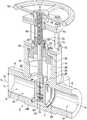
- FIG. 1is a perspective cross-sectional view of a parallel disc gate valve.
- FIG. 2is a top perspective view of one embodiment of the disc gate valve shown in FIG. 1 .
- FIG. 3is a cross-sectional view of a lower portion of the valve assembly.
- FIG. 4is an enlarged vertical cross-sectional view of the valve seat and gates shown in FIG. 3 .
- FIG. 5is an enlarged horizontal cross-sectional view of the valve seat and gates.
- FIG. 6is a vertical cross-sectional view of the valve body without the valve seats installed.
- FIG. 7Ais a perspective view of a block forged body.
- FIG. 7Bis a perspective view of the valve body after machining of the portions of the interior and exterior thereof.
- FIG. 8is a vertical cross-sectional view of the valve body shown in FIG. 7B .
- FIG. 9is a top view of valve body shown in FIG. 8 after additional machining.
- FIG. 10is a vertical cross-sectional view of the valve body taken along line 10 - 10 of FIG. 9 .
- FIG. 11is a horizontal cross-sectional view of the valve body taken along line 11 - 11 of FIG. 10 .
- FIGS. 12A-Kshow a process flow for a block forged valve body.
- the term “plurality,” as used herein,means two or more.
- the terms “outboard” and “inboard”refer to the relative position of different features relative to a common axis or plane.
- the term “coupled”means connected to or engaged with, whether directly or indirectly, for example with an intervening member, and does not require the engagement to be fixed or permanent, although it may be fixed or permanent (or integral).
- the terms “first,” “second,” and so on, as used hereinare not meant to be assigned to a particular component so designated, but rather are simply referring to such components in the numerical order as addressed, meaning that a component designated as “first” may later be a “second” such component, depending on the order in which it is referred.
- first diametermay be later referred to as a “second” diameter depending on the order in which they are referred. It should also be understood that designation of “first” and “second” does not necessarily mean that the two components or values so designated are different, meaning for example a first diameter may be the same as a second diameter, with each simply being applicable to separate components.
- vertical and horizontalrefer to the orientation of various components as shown in the drawings, but with the understanding that those components may be rotated and used in other orientations.
- a gate valve 2is shown as including a one-piece valve body having an inverted T-shape, with a pair of cylindrical end portions 6 defining an interior flow passageway 8 that extends along a longitudinal axis 10 between opposite ends of the body.
- the end portionseach have an interior passageway 12 , which may be cylindrical or tapered with a varying diameter, defined by a minimum diameter (d 1 ), for example and without limitation 7.76 inches to 24.63 inches, of the flow passageway 8 .
- a cylindrical neck portion 14extends upwardly from the end portions.
- the neck portionincludes an annular flange or top surface 16 defining a top of the body.
- the neck portiondefines an interior chamber 18 having a circumferential side wall 20 , a bottom defined by a floor 22 and an open top.
- the side wallincludes a step 24 defining upper and lower portions 26 , 28 of the chamber, each with a diameter d 2 (e.g., 13.3 inches to 32.5 inches), d 3 (e.g., 12.62 inches to 30.25 inches).
- the chamberextends downwardly into the neck portion from the top along a longitudinal axis 30 that extends transverse to the longitudinal axis.
- the axes 10 , 30are orthogonal or perpendicular. It should be understood that the chamber may have a cross-sectional shape other than a circle, including for example and without limitation various polygonal shapes, or other elliptical shapes.
- a passageway 32extends through the floor between the chamber 28 and the flow passageway 8 .
- the passagewayhas a rectangular shape, with rounded corners 34 as shown in FIGS. 2, 5, 6 and 11 , and extends down through the flow passageway 8 as shown in FIG. 6 to form a lower chamber defining in part the flow passageway.
- the rectangular shapeis dimensioned and accommodates the movement of a carriage and disc components of the valve through the passageway as further disclosed herein.
- the width of the passagewayis slightly greater than the diameter of the chamber, such that channels are formed on opposite sides of the wall.
- the corners 34may be tangent with the surface of the chamber, or be positioned radially inwardly from the surface.
- a pair of longitudinal grooves 38extends along opposite sides of the chamber 18 , passageway 32 and lower chamber as shown in FIG. 6 in a direction of the longitudinal axis 30 . Due to the difference in the shapes of the passageway 32 and chamber, a portion of the floor includes a pair of spaced apart shelf portions 36 , each having a semi-circular shape in the embodiment configured with a circular cross section for the chamber and a rectangular cross section for the passageway. In other embodiments, the shelves may have other shapes depending on the mutual shapes and intersection of the chamber and passageway.
- An annular shoulder 40extends along the longitudinal axis circumferentially around the flow passageway 8 beneath each of the shelf portions 36 .
- the annular shoulderhas a circumferential surface 42 and a rear surface 44 defining a corner.
- the circumferential surface portion of the annular shoulderhas a minimum diameter d 4 that is greater than the minimum diameter of the flow passageway, and a depth D 1 (e.g., 1.2 inches to 8.37 inches), otherwise referred to as a width.
- the annular shoulderis coaxial with the flow passageway 8 along axis 10 .
- a pair of annular valve seats 50are disposed in the annular shoulders 40 .
- the valve seatsare made of SA 182 F91/SA 335 P91.
- the valve seatseach have a front side 52 facing each other and a backside 54 facing the away from each other.
- the backside 54is engaged with a rear wall of a respective annular shoulder 40 .
- the valve seatseach have a circumferential surface 56 having a second depth D 2 , otherwise referred to as a width.
- the depth D 2is greater than the depth D 1 , or more than 100% of the depth D 1 such that engagement of each valve seat 40 by a corresponding valve disc 82 is ensured as further explained below, and preferably the depth D 2 is between 125% and 135% of the depth D 1 , including for example a 0.4 inch overhang across the range.
- the entirety of the circumferential surface 42 having depth D 1is in contact with the circumferential surface 56 of a corresponding valve seat, while in other embodiments at least 75% of the circumferential surface is in contact. It should be understood that the valve seat is axially fixed relative to the annular shoulder.
- a second annular shoulder 46which may be formed as a groove, is formed in each of the end portions outboard of the first annular shoulder relative to the longitudinal axis 30 .
- the second annular shoulder 46has a minimum diameter (e.g., 8.41 to 24.88 inches), extends along the longitudinal axis 10 and is coaxial with the first annular shoulder 40 and the flow passageway 8 .
- the diameter of the second annular shoulderis less than the diameter of the first annular shoulder, and greater than the minimum diameter of the flow channel.
- a cavity 60is formed at the bottom of the passageway 32 beneath the flow passageway 8 in horizontal alignment with the overlying chamber along the longitudinal axis 30 .
- the valve seat 50is welded to the end portions of the body at the second annular shoulder or groove 46 , which abuts the backside of the valve seats. As shown in FIGS. 1 and 3-5 , the valve seat 50 is encapsulated by the valve body, and in particular the annular shoulder 40 , meaning that at least 75% of the depth D 2 of the valve seat is surrounded by the valve body around the entire circumference of the valve seat. As mentioned, the valve seat may be made of SA 182 F91/SA 335 P91, and may include a hard sealing surface, or hardfacing, on the front side thereof, including for example and without limitation a Stellite® hardfacing.
- a bonnet 70is secured to the top of the valve body with a plurality of fasteners 72 to close the open top of the chamber 18 .
- a pressure seal 74is disposed in the chamber below the bonnet and is coupled thereto, while a yoke 76 is coupled to and extends upwardly from the top of the bonnet and supports a valve stem 80 .
- the valve stem 80is a rising stem, which is threadably engaged by an actuator 78 , shown as a wheel.
- a pair of discs 82are coupled to a distal end of the stem with a carriage 84 , which includes guides 88 that slide along the grooves in the chamber.
- a plurality of (shown as two) compression springs 86are disposed between the discs, and bias the discs outwardly away from each other. The discs 86 are biased into engagement with the valve seats 50 when the valve is in a closed position, or with the discs disposed in the flow passageway to stop flow therethrough.
- a portion of the carriage 84may be disposed, or received, in the cavity 60 when the valve is in the closed position.
- the stem 80may be rotated by the actuator 78 , causing the stem 80 , discs 82 and carriage 84 to move upwardly from the flow passageway 8 through the passageway 32 in the floor and into the chamber 18 , whereinafter the discs are in an open position such that the flow passageway 8 is not blocked by the discs.
- the discs 82may be parallel or arranged at an angle relative to each other in a wedge configuration.
- the actuator 78is rotated in the opposite direction, causing the discs to move downwardly into the flow passageway 8 and engage the valve seats 50 .
- a one-piece bodyis formed by block (hot) forging a block 90 of ASTM A182 Grade F91 Alloy Steel, which has opposite ends 92 , opposite sides 94 , a top 96 and a bottom 98 (see FIGS. 7A and 12A ).
- the lengthmay be from 33 inches to 56 inches, the width from 20 inches to 40 inches and the height from 30 inches to 64 inches.
- Rough machiningmay be performed to shape the outside surface of the end portions and head portion, defining a generally inverted T-shape, with a central block, having a rectangular prism 100 shape that which may be a cube in one embodiment, cylindrical end portions 102 extending from opposite ends of the prism, and a cylindrical neck portion 104 extending upwardly from the top of the prism.
- the prismprovides increased strength and thickness, while also providing a flat bottom surface 106 for ease of mounting and locating of the valve body (see FIG. 12B ).
- the term “machining”refers to any of various processes in which a piece of raw material is reconfigured into a desired final shape and size by a controlled material-removal process, for example with the use of machine tools.
- CNCComputer numerical control
- VTLvertical turning latch
- a through hole or flow bore 108is machined (e.g., using VTL) along the first longitudinal axis 10 between the opposite ends to define the flow passageway.
- the through holemay be cylindrical, or have a tapered, frusto-conical shape with a minimum diameter as disclosed herein.
- Multiple machining operationsmay be performed to configure the chamber 18 with different upper and lower portions.
- the processincludes machining (e.g., VTL) the chamber 18 from the top 96 of the body along the longitudinal axis 30 .
- Multiple machining operationsmay be performed to configure the chamber with different upper and lower portions as disclosed herein, as shown in FIGS. 12D-H .
- the flow bore 108 and chamber 18are used as references for further machining, using for example a horizontal machining center (HMC).
- HMChorizontal machining center
- the configuration of the chamber 18 on the top sideis further refined using a CNC lathe as shown in FIG. 12E .
- a CNC latheis also used to machine the final configuration of the through hole 108 as shown in FIGS. 12 F and G, finishing the upstream and downstream ends.
- the processfurther includes machining the passageway 32 , for example using rectangular pocket milling through the floor between the chamber and the through hole 108 , and further down through the through hole which may occur before or after one or both of the machining of the through hole and chamber.
- the machiningmay further include machining the cavity 60 in the bottom of the body below the flow passageway as the passageway 32 is machined.
- the machining of the passageway 32 , or of the chamber,forms the shelf portions 36 .
- the channels and grooves 38are also machined into the chamber, the passageway 32 and lower chamber and the flow passageway, as shown in FIG. 12J , for example using a milling process.
- the processfurther includes machining (see FIGS. 12G and H) the first annular shoulders 40 under the spaced apart shelf portions 36 , and machining the second annular shoulders or grooves 46 outboard of the first annular shoulders, again in either sequence.
- the first shouldersmay be formed by the machining of the passage way 32 into the central cylindrical cavity 115 formed by the upstream and downstream operations defining upstream and downstream 111 , 113 portions thereof.
- Top face holesmay be formed by drilling as shown in FIG. 12I .
- the outside corners of the prism block 100may be chamfered as shown in FIG. 12K , for example using HMC.
- the overall outer surfacemay then be deburred, for example using a grinder.
- the processincludes inserting a valve seat 50 into each of the annular shoulders, which fully encapsulate the valve seats, and with the entirety of the depth D 1 of the circumferential surface 42 being in contact with a respective valve seat.
- the valve seatsare then connected to the body by welding the backside of the valve seat to the body, and in particular by welding the valve seat to the body along the second annular shoulder.
Landscapes
- Engineering & Computer Science (AREA)
- General Engineering & Computer Science (AREA)
- Mechanical Engineering (AREA)
- Lift Valve (AREA)
- Valve Housings (AREA)
Abstract
Description
Claims (23)
Priority Applications (1)
| Application Number | Priority Date | Filing Date | Title |
|---|---|---|---|
| US16/458,704US11047487B2 (en) | 2018-07-05 | 2019-07-01 | Method for manufacturing a block forged valve body with a fully encapsulated seat ring |
Applications Claiming Priority (2)
| Application Number | Priority Date | Filing Date | Title |
|---|---|---|---|
| US201862694247P | 2018-07-05 | 2018-07-05 | |
| US16/458,704US11047487B2 (en) | 2018-07-05 | 2019-07-01 | Method for manufacturing a block forged valve body with a fully encapsulated seat ring |
Publications (2)
| Publication Number | Publication Date |
|---|---|
| US20200011432A1 US20200011432A1 (en) | 2020-01-09 |
| US11047487B2true US11047487B2 (en) | 2021-06-29 |
Family
ID=69059764
Family Applications (1)
| Application Number | Title | Priority Date | Filing Date |
|---|---|---|---|
| US16/458,704ActiveUS11047487B2 (en) | 2018-07-05 | 2019-07-01 | Method for manufacturing a block forged valve body with a fully encapsulated seat ring |
Country Status (6)
| Country | Link |
|---|---|
| US (1) | US11047487B2 (en) |
| EP (1) | EP3817873A4 (en) |
| KR (1) | KR102751639B1 (en) |
| CN (1) | CN113165051B (en) |
| CA (1) | CA3111375A1 (en) |
| WO (1) | WO2020009984A1 (en) |
Families Citing this family (7)
| Publication number | Priority date | Publication date | Assignee | Title |
|---|---|---|---|---|
| US10113661B2 (en)* | 2016-08-30 | 2018-10-30 | Griswold Controls, Llc | Flow control valve |
| CN113000775B (en)* | 2021-03-15 | 2023-05-02 | 大庆市顺康石油科技开发有限公司 | Forging method for multi-way valve at wellhead of oil production well |
| CN115126918B (en)* | 2021-03-24 | 2025-08-12 | 中核苏阀科技实业股份有限公司 | High-temperature high-pressure forged steel high-performance gate valve body with guide ribs and manufacturing method |
| CN115126919B (en)* | 2021-03-24 | 2025-08-12 | 中核苏阀科技实业股份有限公司 | High-temperature high-pressure forged steel high-performance gate valve body with guide groove and manufacturing method |
| CN114110193B (en)* | 2021-11-30 | 2024-11-08 | 常进芬 | A corrosion-resistant and pressure-resistant valve joint and its manufacturing process |
| CN114523269B (en)* | 2022-03-04 | 2023-07-14 | 安徽新欧力电器有限公司 | Refrigerator part processing system and method |
| CN115194411B (en)* | 2022-07-21 | 2024-06-14 | 玉环云泰铜业有限公司 | Tap seat processing technology |
Citations (22)
| Publication number | Priority date | Publication date | Assignee | Title |
|---|---|---|---|---|
| US1803889A (en)* | 1927-03-14 | 1931-05-05 | Charles F H Bohnhardt | Noncorroding valve |
| US1828478A (en) | 1925-05-19 | 1931-10-20 | Columbus Machine Company | Gate valve and method of making same |
| US2065035A (en) | 1935-04-22 | 1936-12-22 | Taylor James Hall | Valve housing and method of making same |
| US3434692A (en)* | 1967-02-23 | 1969-03-25 | Cassius L Tillman | Bifaced wedged gate valve |
| US3486733A (en) | 1967-09-01 | 1969-12-30 | Jamesbury Corp | Seat ring for ball valves |
| US4208035A (en)* | 1978-02-13 | 1980-06-17 | Acf Industries, Incorporated | Metal gate valve seat having a flexible front lip face seal |
| US4443920A (en) | 1981-09-08 | 1984-04-24 | Oliver John P | Method of manufacturing a gate valve body |
| US4566671A (en) | 1983-11-14 | 1986-01-28 | John Beson | Gate valve having a secondary seal |
| US4911407A (en) | 1989-03-17 | 1990-03-27 | Paul Jr Herman L | Valve seat structure and assembly |
| US6401747B1 (en)* | 2000-07-13 | 2002-06-11 | Fmc Corporation | Gate valve |
| US6969047B2 (en) | 1999-11-23 | 2005-11-29 | Swagelok Company | Ball valve seat seal |
| CN201306481Y (en) | 2008-11-03 | 2009-09-09 | 大连大高阀门有限公司 | Nuclear grade one large-caliber forged steel full-flow swing type check valve |
| US20110277985A1 (en) | 2009-02-04 | 2011-11-17 | Cameron International Corporation | Drive sleeve and sealing mechanism for non-rising stem gate valve |
| US8205860B2 (en) | 2006-08-14 | 2012-06-26 | Yongsheng Song | Valve with a structure for mitigating abrasive wear or galling of sealing surfaces between a seat ring and a closure member during their relative sliding contact with each other |
| US8403296B2 (en) | 2010-11-29 | 2013-03-26 | Vetco Gray Inc. | Metal seat seal with flexible sealing edge |
| US8689996B2 (en) | 2011-09-29 | 2014-04-08 | General Electric Company | System for locking container assembly |
| CN203627856U (en) | 2013-12-27 | 2014-06-04 | 浙江科正阀门有限公司 | Forged steel gate valve |
| US20160356399A1 (en)* | 2011-06-20 | 2016-12-08 | Jianchao Shu | Trunnion control gate valve for severe service |
| CN206159560U (en) | 2016-11-09 | 2017-05-10 | 尚绪河 | Qi shihuan that revolves that structure is succinct closes silence check valve |
| CN107671221A (en) | 2017-11-27 | 2018-02-09 | 二十二冶集团精密锻造有限公司 | The not shaping dies and manufacturing process of equal tee valve body |
| US9897215B2 (en) | 2012-12-31 | 2018-02-20 | Vetco Gray Inc. | Multi-valve seat seal assembly for a gate valve |
| CN207715831U (en) | 2017-10-20 | 2018-08-10 | 中核苏阀科技实业股份有限公司 | A pin shaft built-in swing check valve |
Family Cites Families (8)
| Publication number | Priority date | Publication date | Assignee | Title |
|---|---|---|---|---|
| US1858927A (en)* | 1930-01-04 | 1932-05-17 | Victory Valves Ltd | Method of making valves |
| US2869819A (en)* | 1954-06-25 | 1959-01-20 | Acf Ind Inc | Gate valve |
| US3463446A (en)* | 1967-03-13 | 1969-08-26 | Acf Ind Inc | Low stress stem connection |
| US4515347A (en)* | 1982-12-27 | 1985-05-07 | Joy Manufacturing Company | Valve seat structure |
| DE3942313A1 (en)* | 1989-12-21 | 1991-06-27 | Bosch Gmbh Robert | Double seat control valve - is for pneumatic vehicle braking system and has connection between pressure chamber and annular chamber |
| CN205298736U (en)* | 2015-12-29 | 2016-06-08 | 上海瑞托阀门科技有限公司 | Whole die forging ultra -low temperature upper assembling type connecting rod ball ball valve |
| JP6640637B2 (en)* | 2016-03-30 | 2020-02-05 | ヴィオニア日信ブレーキシステムジャパン株式会社 | Solenoid valve, vehicle brake fluid pressure control device, and method of manufacturing electromagnetic valve |
| CN206290734U (en)* | 2016-12-20 | 2017-06-30 | 温州电泰阀门有限公司 | A kind of boxing formula solid forging gate valve |
- 2019
- 2019-07-01KRKR1020217003685Apatent/KR102751639B1/enactiveActive
- 2019-07-01USUS16/458,704patent/US11047487B2/enactiveActive
- 2019-07-01CNCN201980058413.6Apatent/CN113165051B/enactiveActive
- 2019-07-01EPEP19830826.4Apatent/EP3817873A4/enactivePending
- 2019-07-01CACA3111375Apatent/CA3111375A1/enactivePending
- 2019-07-01WOPCT/US2019/040109patent/WO2020009984A1/ennot_activeCeased
Patent Citations (22)
| Publication number | Priority date | Publication date | Assignee | Title |
|---|---|---|---|---|
| US1828478A (en) | 1925-05-19 | 1931-10-20 | Columbus Machine Company | Gate valve and method of making same |
| US1803889A (en)* | 1927-03-14 | 1931-05-05 | Charles F H Bohnhardt | Noncorroding valve |
| US2065035A (en) | 1935-04-22 | 1936-12-22 | Taylor James Hall | Valve housing and method of making same |
| US3434692A (en)* | 1967-02-23 | 1969-03-25 | Cassius L Tillman | Bifaced wedged gate valve |
| US3486733A (en) | 1967-09-01 | 1969-12-30 | Jamesbury Corp | Seat ring for ball valves |
| US4208035A (en)* | 1978-02-13 | 1980-06-17 | Acf Industries, Incorporated | Metal gate valve seat having a flexible front lip face seal |
| US4443920A (en) | 1981-09-08 | 1984-04-24 | Oliver John P | Method of manufacturing a gate valve body |
| US4566671A (en) | 1983-11-14 | 1986-01-28 | John Beson | Gate valve having a secondary seal |
| US4911407A (en) | 1989-03-17 | 1990-03-27 | Paul Jr Herman L | Valve seat structure and assembly |
| US6969047B2 (en) | 1999-11-23 | 2005-11-29 | Swagelok Company | Ball valve seat seal |
| US6401747B1 (en)* | 2000-07-13 | 2002-06-11 | Fmc Corporation | Gate valve |
| US8205860B2 (en) | 2006-08-14 | 2012-06-26 | Yongsheng Song | Valve with a structure for mitigating abrasive wear or galling of sealing surfaces between a seat ring and a closure member during their relative sliding contact with each other |
| CN201306481Y (en) | 2008-11-03 | 2009-09-09 | 大连大高阀门有限公司 | Nuclear grade one large-caliber forged steel full-flow swing type check valve |
| US20110277985A1 (en) | 2009-02-04 | 2011-11-17 | Cameron International Corporation | Drive sleeve and sealing mechanism for non-rising stem gate valve |
| US8403296B2 (en) | 2010-11-29 | 2013-03-26 | Vetco Gray Inc. | Metal seat seal with flexible sealing edge |
| US20160356399A1 (en)* | 2011-06-20 | 2016-12-08 | Jianchao Shu | Trunnion control gate valve for severe service |
| US8689996B2 (en) | 2011-09-29 | 2014-04-08 | General Electric Company | System for locking container assembly |
| US9897215B2 (en) | 2012-12-31 | 2018-02-20 | Vetco Gray Inc. | Multi-valve seat seal assembly for a gate valve |
| CN203627856U (en) | 2013-12-27 | 2014-06-04 | 浙江科正阀门有限公司 | Forged steel gate valve |
| CN206159560U (en) | 2016-11-09 | 2017-05-10 | 尚绪河 | Qi shihuan that revolves that structure is succinct closes silence check valve |
| CN207715831U (en) | 2017-10-20 | 2018-08-10 | 中核苏阀科技实业股份有限公司 | A pin shaft built-in swing check valve |
| CN107671221A (en) | 2017-11-27 | 2018-02-09 | 二十二冶集团精密锻造有限公司 | The not shaping dies and manufacturing process of equal tee valve body |
Non-Patent Citations (2)
| Title |
|---|
| International Search Report and Written Opinion for PCT Application No. PCT/US2019/040109, dated Sep. 20, 2019, 9 pgs. |
| International Search Report and Written Opinion for PCT Application No. PCT/US2019/058851, dated Jan. 23, 2020, 14 pgs. |
Also Published As
| Publication number | Publication date |
|---|---|
| WO2020009984A1 (en) | 2020-01-09 |
| US20200011432A1 (en) | 2020-01-09 |
| CN113165051B (en) | 2023-10-27 |
| EP3817873A1 (en) | 2021-05-12 |
| KR102751639B1 (en) | 2025-01-10 |
| KR20210059698A (en) | 2021-05-25 |
| CA3111375A1 (en) | 2020-01-09 |
| CN113165051A (en) | 2021-07-23 |
| EP3817873A4 (en) | 2022-03-16 |
Similar Documents
| Publication | Publication Date | Title |
|---|---|---|
| US11047487B2 (en) | Method for manufacturing a block forged valve body with a fully encapsulated seat ring | |
| CA2824675C (en) | Bonnet for three-way valve | |
| US20160238002A1 (en) | Plunger lift assembly | |
| US8631572B2 (en) | Method for the production of a piston for an internal combustion engine | |
| US20030089398A1 (en) | Replaceable valve seat ring with enhanced flow design | |
| US11598449B2 (en) | Compact multi-stage control valve trim | |
| EP1579131B1 (en) | Seat ring for valves | |
| US20140109970A1 (en) | Metal cone plug valve | |
| US11649897B1 (en) | Valve plug apparatus for use with control valves | |
| US11480254B2 (en) | Method for manufacturing a block forged swing check valve body with a fully encapsulated seat ring | |
| US20150021506A1 (en) | Apparatus to attach a fluid valve bonnet | |
| US4967787A (en) | Unitized disc flow control assembly for a restrictor valve | |
| JP4352390B2 (en) | Piston structure | |
| US3473785A (en) | Valve body for globe valves or the like | |
| US9545659B2 (en) | Poppet pin ejector | |
| US11090713B2 (en) | Bi-metal valve body casting and method of making same | |
| US20210071779A1 (en) | Tapered Anti-Cavitation Cage | |
| JP2010101357A (en) | Diaphragm valve device | |
| US516658A (en) | Process of seating valve-bodies | |
| KR102394370B1 (en) | Assembling Type Gate Valve | |
| JPH0771626A (en) | Ball for ball valve | |
| CN103851219A (en) | Adjusting valve used for adjusting hydraulic volume flow rate |
Legal Events
| Date | Code | Title | Description |
|---|---|---|---|
| FEPP | Fee payment procedure | Free format text:ENTITY STATUS SET TO UNDISCOUNTED (ORIGINAL EVENT CODE: BIG.); ENTITY STATUS OF PATENT OWNER: LARGE ENTITY | |
| STPP | Information on status: patent application and granting procedure in general | Free format text:DOCKETED NEW CASE - READY FOR EXAMINATION | |
| STPP | Information on status: patent application and granting procedure in general | Free format text:NON FINAL ACTION MAILED | |
| STPP | Information on status: patent application and granting procedure in general | Free format text:NOTICE OF ALLOWANCE MAILED -- APPLICATION RECEIVED IN OFFICE OF PUBLICATIONS | |
| AS | Assignment | Owner name:MCC HOLDINGS, INC. D/B/A CRANE CHEMPHARMA & ENERGY, TEXAS Free format text:ASSIGNMENT OF ASSIGNORS INTEREST;ASSIGNORS:KULKARNI, SUDHIR K.;LEDGETT, TYLER A.;CHAUDHARI, SACHIN S.;AND OTHERS;SIGNING DATES FROM 20210319 TO 20210322;REEL/FRAME:055675/0679 | |
| STPP | Information on status: patent application and granting procedure in general | Free format text:PUBLICATIONS -- ISSUE FEE PAYMENT RECEIVED | |
| STPP | Information on status: patent application and granting procedure in general | Free format text:PUBLICATIONS -- ISSUE FEE PAYMENT VERIFIED | |
| STPP | Information on status: patent application and granting procedure in general | Free format text:AWAITING TC RESP, ISSUE FEE PAYMENT VERIFIED | |
| STPP | Information on status: patent application and granting procedure in general | Free format text:PUBLICATIONS -- ISSUE FEE PAYMENT VERIFIED | |
| STCF | Information on status: patent grant | Free format text:PATENTED CASE | |
| AS | Assignment | Owner name:CRANE CHEMPHARMA & ENERGY CORP., TEXAS Free format text:ASSIGNMENT OF ASSIGNORS INTEREST;ASSIGNOR:MCC HOLDINGS, INC.;REEL/FRAME:058610/0495 Effective date:20211215 | |
| MAFP | Maintenance fee payment | Free format text:PAYMENT OF MAINTENANCE FEE, 4TH YEAR, LARGE ENTITY (ORIGINAL EVENT CODE: M1551); ENTITY STATUS OF PATENT OWNER: LARGE ENTITY Year of fee payment:4 |