US11047249B2 - Labyrinth seal with passive check valve - Google Patents
Labyrinth seal with passive check valveDownload PDFInfo
- Publication number
- US11047249B2 US11047249B2US16/400,137US201916400137AUS11047249B2US 11047249 B2US11047249 B2US 11047249B2US 201916400137 AUS201916400137 AUS 201916400137AUS 11047249 B2US11047249 B2US 11047249B2
- Authority
- US
- United States
- Prior art keywords
- flow channel
- flow
- gas turbine
- turbine engine
- outer circumferential
- Prior art date
- Legal status (The legal status is an assumption and is not a legal conclusion. Google has not performed a legal analysis and makes no representation as to the accuracy of the status listed.)
- Active, expires
Links
Images

Classifications
- F—MECHANICAL ENGINEERING; LIGHTING; HEATING; WEAPONS; BLASTING
- F01—MACHINES OR ENGINES IN GENERAL; ENGINE PLANTS IN GENERAL; STEAM ENGINES
- F01D—NON-POSITIVE DISPLACEMENT MACHINES OR ENGINES, e.g. STEAM TURBINES
- F01D11/00—Preventing or minimising internal leakage of working-fluid, e.g. between stages
- F01D11/02—Preventing or minimising internal leakage of working-fluid, e.g. between stages by non-contact sealings, e.g. of labyrinth type
- F—MECHANICAL ENGINEERING; LIGHTING; HEATING; WEAPONS; BLASTING
- F16—ENGINEERING ELEMENTS AND UNITS; GENERAL MEASURES FOR PRODUCING AND MAINTAINING EFFECTIVE FUNCTIONING OF MACHINES OR INSTALLATIONS; THERMAL INSULATION IN GENERAL
- F16J—PISTONS; CYLINDERS; SEALINGS
- F16J15/00—Sealings
- F16J15/16—Sealings between relatively-moving surfaces
- F16J15/40—Sealings between relatively-moving surfaces by means of fluid
- F—MECHANICAL ENGINEERING; LIGHTING; HEATING; WEAPONS; BLASTING
- F16—ENGINEERING ELEMENTS AND UNITS; GENERAL MEASURES FOR PRODUCING AND MAINTAINING EFFECTIVE FUNCTIONING OF MACHINES OR INSTALLATIONS; THERMAL INSULATION IN GENERAL
- F16J—PISTONS; CYLINDERS; SEALINGS
- F16J15/00—Sealings
- F16J15/44—Free-space packings
- F16J15/447—Labyrinth packings
- F16J15/4472—Labyrinth packings with axial path
- F—MECHANICAL ENGINEERING; LIGHTING; HEATING; WEAPONS; BLASTING
- F16—ENGINEERING ELEMENTS AND UNITS; GENERAL MEASURES FOR PRODUCING AND MAINTAINING EFFECTIVE FUNCTIONING OF MACHINES OR INSTALLATIONS; THERMAL INSULATION IN GENERAL
- F16J—PISTONS; CYLINDERS; SEALINGS
- F16J15/00—Sealings
- F16J15/44—Free-space packings
- F16J15/447—Labyrinth packings
- F16J15/4476—Labyrinth packings with radial path
- F—MECHANICAL ENGINEERING; LIGHTING; HEATING; WEAPONS; BLASTING
- F05—INDEXING SCHEMES RELATING TO ENGINES OR PUMPS IN VARIOUS SUBCLASSES OF CLASSES F01-F04
- F05D—INDEXING SCHEME FOR ASPECTS RELATING TO NON-POSITIVE-DISPLACEMENT MACHINES OR ENGINES, GAS-TURBINES OR JET-PROPULSION PLANTS
- F05D2240/00—Components
- F05D2240/10—Stators
- F05D2240/12—Fluid guiding means, e.g. vanes
- F05D2240/126—Baffles or ribs
Definitions
- This applicationrelates to a gas turbine engine that includes a component comprising a labyrinth seal with a passive check valve.
- Gas turbine enginestypically include a fan delivering air into a bypass duct as bypass air and into a compressor as core air.
- the airis compressed and delivered into a combustor section where the air is mixed with fuel and ignited. Products of the combustion pass downstream over turbine rotors, which causes the turbine rotors to rotate.
- a labyrinth sealis used to seal a bearing compartment.
- a labyrinth sealis a close clearance seal that can seal a cavity from both air and oil transfer.
- Labyrinth sealswhich are also referred to as knife edge seals, include a rotating member with sharp points, e.g., knife edges, that rotate in close proximity to a static structure. This close proximity reduces the overall leakage area that is exposed between two cavities.
- labyrinth sealsare configured to use a naturally forming vortex that occurs directly behind the knife edge to further reduce leakage.
- labyrinth sealsare cost effective and easy to maintain, they are not the most efficient of seals.
- a gas turbine engine componentin a featured embodiment, includes a static component with at least one first flow channel.
- the labyrinth sealrotates relative to the static component.
- the labyrinth sealis spaced from the static component by a second flow channel.
- the flow passing between the labyrinth seal and the static componentwill have a first portion that travels through the at least one first flow channel and a second portion that travels through the second flow channel with the first portion of the flow being reintroduced into the second flow channel to create a flow restriction.
- the labyrinth sealrotates about an engine center axis and wherein the second flow channel comprises a gap that extends circumferentially about the engine center axis.
- the labyrinth sealrotates about an engine center axis and wherein the second flow channel comprises a gap that extends circumferentially about the engine center axis.
- the labyrinth sealhas an outer circumferential surface with a plurality of knives extending radially outwardly of the outer circumferential surface and being axially spaced apart from each other.
- the static componenthas an inner circumferential surface that faces the outer circumferential surface of the labyrinth seal, and wherein the at least one first flow channel is formed in the inner circumferential surface and comprises a curved channel having an inlet that receives the first portion of the flow and an outlet that reintroduces the first portion into the second flow channel.
- the inlet and outletare positioned axially between a pair of adjacent knives.
- the at least one first flow channelcomprises a plurality of first flow channels that are axially spaced apart from each other along the inner circumferential surface of the static component.
- one first flow channelis positioned axially between each pair of adjacent knives.
- the at least one first flow channelextends circumferentially about the engine center axis, and wherein the at least one first flow channel has a first path portion that directs flow in a generally axial direction and a second path portion that directs the flow along a curved flow path that curves in a radially inward direction.
- the at least one first flow channelis formed by a reduced portion that is spaced apart from a main body of the static component.
- the reduced portionhas a cross-section that comprises a tear-drop shape.
- the tear-drop shapehas a pointed tip and a rounded base, and wherein the inlet is at the pointed tip and the outlet is at the rounded base.
- a distal end of a knife positioned upstream of the reduced portionis at a generally same radial location relative to the engine center axis as the pointed tip.
- the at least one supportcomprises a plurality of supports that are circumferentially spaced apart from each other.
- flow in a first direction through the second flow channelis more restrictive than flow through the second flow channel in a second direction that is opposite of the first direction.
- a methodin another featured embodiment, includes providing a static component with at least one first flow channel, spacing a labyrinth seal from the static component by a second flow channel, directing flow passing between the labyrinth seal and the static component to have a first portion that travels through the at least one first flow channel and a second portion that travels through the second flow channel, and reintroducing the first portion of the flow into the second flow channel to create a flow restriction.
- a methodin another embodiment according to any of the previous embodiments, includes rotating the labyrinth seal relative to the static component about an engine center axis and forming the second flow channel as a gap that extends circumferentially about the engine center axis.
- the labyrinth sealhas an outer circumferential surface with a plurality of knives extending radially outwardly of the outer circumferential surface and being axially spaced apart from each other, and wherein the at least one first flow channel extends circumferentially about the engine center axis, and including forming the at least one first flow channel with a first path portion that directs flow in a generally axial direction and a second path portion that directs the flow along a curved flow path that curves in a radially inward direction.
- a methodin another embodiment according to any of the previous embodiments, includes forming the at least one first flow channel as a plurality of first flow channels that are axially spaced apart from each other along an inner circumferential surface of the static component, and positioning one first flow channel axially between each pair of adjacent knives.
- a methodin another embodiment according to any of the previous embodiments, includes forming the at least one first flow channel as a reduced portion that is spaced apart from a main body of the static component, wherein the reduced portion has a cross-section that comprises a tear-drop shape.
- FIG. 1schematically shows a gas turbine engine.
- FIG. 2shows a perspective illustration of a portion of a static structure and a labyrinth seal assembly as used in the gas turbine engine of FIG. 1 .
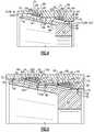
- FIG. 3is a perspective view of an inner circumferential surface of the static structure of FIG. 2 .
- FIG. 4is a side section view of FIG. 2 showing first and second flow channels.
- FIG. 5is a view similar to FIG. 4 but showing a flow path of fluid within the first and second flow channels where a width of the flow lines is representative of a pressure at each location and is intended to represent locations at which restrictions occur.
- FIG. 1schematically illustrates a gas turbine engine 20 .
- the gas turbine engine 20is disclosed herein as a two-spool turbofan that generally incorporates a fan section 22 , a compressor section 24 , a combustor section 26 and a turbine section 28 .
- the fan section 22drives air along a bypass flow path B in a bypass duct defined within a nacelle 15 , and also drives air along a core flow path C for compression and communication into the combustor section 26 then expansion through the turbine section 28 .
- the exemplary engine 20generally includes a low speed spool 30 and a high speed spool 32 mounted for rotation about an engine central longitudinal axis A relative to an engine static structure 36 via several bearing systems 38 . It should be understood that various bearing systems 38 at various locations may alternatively or additionally be provided, and the location of bearing systems 38 may be varied as appropriate to the application.
- the low speed spool 30generally includes an inner shaft 40 that interconnects a first (or low) pressure compressor 44 and a first (or low) pressure turbine 46 .
- the inner shaft 40is connected to a fan 42 through a speed change mechanism, which in exemplary gas turbine engine 20 is illustrated as a geared architecture 48 to drive the fan 42 at a lower speed than the low speed spool 30 .
- the high speed spool 32includes an outer shaft 50 that interconnects a second (or high) pressure compressor 52 and a second (or high) pressure turbine 54 .
- a combustor 56is arranged in exemplary gas turbine 20 between the high pressure compressor 52 and the high pressure turbine 54 .
- a mid-turbine frame 57 of the engine static structure 36may be arranged generally between the high pressure turbine 54 and the low pressure turbine 46 .
- the mid-turbine frame 57further supports bearing systems 38 in the turbine section 28 .
- the inner shaft 40 and the outer shaft 50are concentric and rotate via bearing systems 38 about the engine central longitudinal axis A which is collinear with their longitudinal axes.
- the core airflowis compressed by the low pressure compressor 44 then the high pressure compressor 52 , mixed and burned with fuel in the combustor 56 , then expanded over the high pressure turbine 54 and low pressure turbine 46 .
- the mid-turbine frame 57includes airfoils 59 which are in the core airflow path C.
- the turbines 46 , 54rotationally drive the respective low speed spool 30 and high speed spool 32 in response to the expansion. It will be appreciated that each of the positions of the fan section 22 , compressor section 24 , combustor section 26 , turbine section 28 , and fan drive gear system 48 may be varied.
- gear system 48may be located aft of the low pressure compressor, or aft of the combustor section 26 or even aft of turbine section 28 , and fan 42 may be positioned forward or aft of the location of gear system 48 .
- the engine 20 in one exampleis a high-bypass geared aircraft engine.
- the engine 20 bypass ratiois greater than about six (6), with an example embodiment being greater than about ten (10)
- the geared architecture 48is an epicyclic gear train, such as a planetary gear system or other gear system, with a gear reduction ratio of greater than about 2.3
- the low pressure turbine 46has a pressure ratio that is greater than about five.
- the engine 20 bypass ratiois greater than about ten (10:1)
- the fan diameteris significantly larger than that of the low pressure compressor 44
- the low pressure turbine 46has a pressure ratio that is greater than about five 5:1.
- Low pressure turbine 46 pressure ratiois pressure measured prior to inlet of low pressure turbine 46 as related to the pressure at the outlet of the low pressure turbine 46 prior to an exhaust nozzle.
- the geared architecture 48may be an epicycle gear train, such as a planetary gear system or other gear system, with a gear reduction ratio of greater than about 2.3:1 and less than about 5:1. It should be understood, however, that the above parameters are only exemplary of one embodiment of a geared architecture engine and that the present invention is applicable to other gas turbine engines including direct drive turbofans.
- the fan section 22 of the engine 20is designed for a particular flight condition—typically cruise at about 0.8 Mach and about 35,000 feet (10,668 meters).
- TSFCThrust Specific Fuel Consumption
- Low fan pressure ratiois the pressure ratio across the fan blade alone, without a Fan Exit Guide Vane (“FEGV”) system.
- the low fan pressure ratio as disclosed herein according to one non-limiting embodimentis less than about 1.45.
- Low corrected fan tip speedis the actual fan tip speed in ft/sec divided by an industry standard temperature correction of [(Tram ° R)/(518.7° R)] 0.5 .
- the “Low corrected fan tip speed” as disclosed herein according to one non-limiting embodimentis less than about 1150 ft/second (350.5 meters/second).
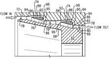
- a labyrinth seal assembly 60is illustrated in FIG. 2 .
- the labyrinth seal assembly 60could be utilized in a bearing compartment for any of the bearing systems 38 as shown in FIG. 1 .
- the labyrinth seal assembly 60could also be used for gas path sealing and/or in high temperature areas where carbon seals cannot be used.
- a knife edge seal or labyrinth seal 62rotates relative to a static component 64 about the engine center axis A.
- the labyrinth seal 62has an outer circumferential surface 66 and an inner circumferential surface 68 .
- the static component 64is a non-rotating component, such as a seal housing for example, that has an outer circumferential surface 70 and an inner circumferential surface 72 .
- the inner circumferential surface 72 of the static component 64is spaced from the outer circumferential surface 66 of the seal 62 and includes at least one first flow channel 74 .
- the labyrinth seal 62is spaced from the static component 64 by a second flow channel 76 .
- the second flow channel 76comprises a gap that extends circumferentially about the engine center axis A. Flow passing between the labyrinth seal 62 and the static component 64 in a first direction (left-to-right as viewed in FIG. 2 ) will have a first portion that travels through the first flow channel 74 and a second portion that travels through the second flow channel 76 with the first portion of the flow being reintroduced into the second flow channel 76 to create a flow restriction.
- the labyrinth seal 62has a plurality of knives 78 extending radially outwardly of the outer circumferential surface 66 .
- the knives 78extend circumferentially about the engine center axis A and are axially spaced apart from each other in a direction along the axis A.
- each knife 78has a base 80 ( FIGS. 4-5 ) at the outer circumferential surface 66 that extends to a distal end 82 comprising a point or reduced section as compared to the base 80 .
- the knives 78can have a stepped configuration as shown in FIG. 2 or can comprise a straight line configuration.
- the inner circumferential surface 72 of the static component 64has an abradable material (not shown) that contacts the distal ends 82 of the knives 78 in response to radial excursions of the labyrinth seal 62 relative to the static component 64 .
- the static component 64has the first flow channel 74 formed in the inner circumferential surface 72 .
- the first flow channel 74comprises a curved channel having an inlet 84 that receives the first portion of the flow and an outlet 86 that reintroduces the first portion of the flow into the second flow channel 76 .
- the inlet 84 and outlet 86are positioned axially between a pair of adjacent knives 78 .
- first flow channels 74there are a plurality of first flow channels 74 that are axially spaced apart from each other along the inner circumferential surface 72 of the static component 64 .
- one first flow channel 74is positioned axially between each pair of adjacent knives 78 .
- the first flow channels 74each extend circumferentially about the engine center axis A.
- the first flow channelhas a first path portion 88 that directs flow in a generally axial direction and a second path portion 90 that directs the flow along a curved flow path that curves in a radially inward direction back toward the second flow channel 76 .
- the first flow channels 74are formed by a reduced portion 92 that is spaced apart from a main body 94 of the static component 64 .
- the reduced portion 92has a cross-section that comprises a tear-drop shape.
- the tear-drop shapehas a pointed tip 96 and a rounded base 98 .
- the inlet 84 of the first flow channel 74is at the pointed tip 96 and the outlet 86 is at the rounded base 98 .
- the reduced portions 92can be the same size or can vary in size as need to provide desired pressure drops. Sizing of the reduced portions 92 , as well as the spacing and/or size of the first 74 and second 76 flow channels is based on boundary conditions, for example.
- At least one support 100is used to hold the reduced portion 92 in a spaced apart relationship relative to the main body 94 .
- the at least one support 100comprises a plurality of supports 100 that are circumferentially spaced apart from each other about the engine center axis A.
- a first support 100is positioned on one side of the reduced portion 92 and a second support 100 is positioned on an opposite side of the reduced portion 92 .
- the supports 100can be aligned with each other across the reduced portion 92 as shown, or could be circumferentially offset from each other.
- the distal end 82 of a knife 78 that is positioned upstream of the reduced portion 92is at a generally same radial location relative to the engine center axis A as the pointed tip 96 of the reduced portion 92 . This is best shown in FIGS. 4-5 .
- FIG. 5shows the flow passing through the first 74 and second 76 flow channels in a first direction (left-to-right in FIG. 5 ).
- first directionleft-to-right in FIG. 5
- fluid passing through the labyrinth knife edge seal 62will be split between the first 74 and second 76 flow channels.
- a first portion 102will enter the first flow channel 74 which comprises an outer diameter curved channel and a second portion 104 will enter the second flow channel 76 which comprises an inner diameter straight channel.
- the first portion of fluid that travels through the curved first flow channel 74is turned at 106 and is subsequently reintroduced into the inward second flow channel 76 causing a flow restriction as indicated at 108 and causing a pressure drop.
- fluid moving in the opposite directioncan flow more freely.
- flow in a first direction through the second flow channel 76is more restrictive than flow through the second flow channel 76 in a second direction that is opposite of the first direction.
- the flow itselfwill not change, i.e. the mass flow remains generally constant through the valve.
- the subject disclosurethus integrates a Fixed Geometry Passive Check Valve (FGPCV) into a static component such as a labyrinth seal housing to create pressure reduction without moving valve parts.
- the FGPCVis made from metal such that wear is not an issue and temperature capability can be quite high.
- Mass flowis generally constant through the valve, and as mass flow reaches each tear-drop segment, the flow spits into the first 74 and second 76 flow channels with the flow from the first flow channel 74 being redirected back to the second flow channel 76 causing a restriction and pressure drop.
- Each segmenthas its own pressure drop and the FGPCV requires mass flow at each segment for the restriction to occur so the valve is never able to seal 100% of the fluid, but with enough segments any leakage can be significantly reduced.
- valvecan act as a check valve. This can be useful in applications where there may be a desire to have flow in one direction, while impeding flow in an opposite direction, in an environment that may not permit a typical mechanical check valve.
- One advantage of such a designcan be a reduction of required knife stages and an improvement of the overall efficiency of the seal. Further, the subject disclosure could result in labyrinth seals that require a smaller axial envelope for integration. Additionally, in applications that may experience large radial excursions, the integration of a FGPCV could enable improved sealing capability where the knife edge clearance has to be larger than desired. Due to the fact that there are no contacting moving parts, the FGPCV will not wear out and is highly resistant to debris and contamination.
Landscapes
- Engineering & Computer Science (AREA)
- General Engineering & Computer Science (AREA)
- Mechanical Engineering (AREA)
- Sealing Using Fluids, Sealing Without Contact, And Removal Of Oil (AREA)
Abstract
Description
Claims (22)
Priority Applications (2)
| Application Number | Priority Date | Filing Date | Title |
|---|---|---|---|
| US16/400,137US11047249B2 (en) | 2019-05-01 | 2019-05-01 | Labyrinth seal with passive check valve |
| EP20169443.7AEP3734019B1 (en) | 2019-05-01 | 2020-04-14 | Labyrinth seal with passive check valve |
Applications Claiming Priority (1)
| Application Number | Priority Date | Filing Date | Title |
|---|---|---|---|
| US16/400,137US11047249B2 (en) | 2019-05-01 | 2019-05-01 | Labyrinth seal with passive check valve |
Publications (2)
| Publication Number | Publication Date |
|---|---|
| US20200347739A1 US20200347739A1 (en) | 2020-11-05 |
| US11047249B2true US11047249B2 (en) | 2021-06-29 |
Family
ID=70289580
Family Applications (1)
| Application Number | Title | Priority Date | Filing Date |
|---|---|---|---|
| US16/400,137Active2039-05-27US11047249B2 (en) | 2019-05-01 | 2019-05-01 | Labyrinth seal with passive check valve |
Country Status (2)
| Country | Link |
|---|---|
| US (1) | US11047249B2 (en) |
| EP (1) | EP3734019B1 (en) |
Cited By (3)
| Publication number | Priority date | Publication date | Assignee | Title |
|---|---|---|---|---|
| US11767863B1 (en) | 2021-09-22 | 2023-09-26 | Joshua Jordan Mathis | Orbicular valvular conduit |
| US12129800B2 (en) | 2022-03-30 | 2024-10-29 | General Electric Company | Fuel nozzle valve seals for high temperature |
| US20240418171A1 (en)* | 2023-06-14 | 2024-12-19 | Hanon Systems | Multipath passive discharge valve for a compressor |
Families Citing this family (2)
| Publication number | Priority date | Publication date | Assignee | Title |
|---|---|---|---|---|
| CN113685234B (en)* | 2021-08-31 | 2022-08-09 | 北京航空航天大学 | Labyrinth sealing device based on hedging principle |
| CN119737202A (en)* | 2024-11-29 | 2025-04-01 | 南京航空航天大学 | A sealing device and method based on bifurcation and confluence resistance increasing mechanism |
Citations (30)
| Publication number | Priority date | Publication date | Assignee | Title |
|---|---|---|---|---|
| US1329559A (en)* | 1916-02-21 | 1920-02-03 | Tesla Nikola | Valvular conduit |
| US2647684A (en)* | 1947-03-13 | 1953-08-04 | Rolls Royce | Gas turbine engine |
| US3572728A (en) | 1968-06-17 | 1971-03-30 | Gen Eelctric Co | Rotary seal |
| US3779345A (en)* | 1972-05-22 | 1973-12-18 | Gen Electric | Emergency lubrication supply system |
| US3927890A (en)* | 1973-09-18 | 1975-12-23 | Westinghouse Electric Corp | Rotating element fluid seal for centrifugal compressor |
| US3940153A (en) | 1974-12-09 | 1976-02-24 | General Motors Corporation | Labyrinth seal |
| SU785575A1 (en) | 1979-03-01 | 1980-12-07 | За витель | Direct-flow labirinth packing |
| US4513975A (en) | 1984-04-27 | 1985-04-30 | General Electric Company | Thermally responsive labyrinth seal |
| US4531358A (en)* | 1980-09-26 | 1985-07-30 | Rolls-Royce Limited | Oil system for aircraft gas turbine engine |
| US5282718A (en)* | 1991-01-30 | 1994-02-01 | United Technologies Corporation | Case treatment for compressor blades |
| US5308225A (en)* | 1991-01-30 | 1994-05-03 | United Technologies Corporation | Rotor case treatment |
| US5431533A (en)* | 1993-10-15 | 1995-07-11 | United Technologies Corporation | Active vaned passage casing treatment |
| US5474417A (en)* | 1994-12-29 | 1995-12-12 | United Technologies Corporation | Cast casing treatment for compressor blades |
| US5607284A (en)* | 1994-12-29 | 1997-03-04 | United Technologies Corporation | Baffled passage casing treatment for compressor blades |
| US6164655A (en) | 1997-12-23 | 2000-12-26 | Asea Brown Boveri Ag | Method and arrangement for sealing off a separating gap, formed between a rotor and a stator, in a non-contacting manner |
| US20060110247A1 (en)* | 2004-11-24 | 2006-05-25 | General Electric Company | Pattern for the surface of a turbine shroud |
| US20070147988A1 (en)* | 2005-12-28 | 2007-06-28 | Hitachi Plant Technologies, Ltd. | Centrifugal compressor and dry gas seal system for use in it |
| US20090297341A1 (en) | 2008-06-02 | 2009-12-03 | General Electric Company | Fluidic sealing for turbomachinery |
| US20110250073A1 (en) | 2010-04-08 | 2011-10-13 | Sudhakar Neeli | Rotor and assembly for reducing leakage flow |
| WO2012052740A1 (en) | 2010-10-18 | 2012-04-26 | University Of Durham | Sealing device for reducing fluid leakage in turbine apparatus |
| US20130341430A1 (en)* | 2012-06-22 | 2013-12-26 | Delavan Inc. | Active purge mechanism with backlow preventer for gas turbine fuel injectors |
| US8900235B2 (en)* | 2004-08-11 | 2014-12-02 | Nlt Spine Ltd. | Devices for introduction into a body via a substantially straight conduit to form a predefined curved configuration, and methods employing such devices |
| US9145786B2 (en)* | 2012-04-17 | 2015-09-29 | General Electric Company | Method and apparatus for turbine clearance flow reduction |
| US20160369925A1 (en) | 2015-06-17 | 2016-12-22 | Rolls-Royce Corporation | Labyrinth seal with tunable flow splitter |
| US20170058689A1 (en)* | 2015-08-25 | 2017-03-02 | Rolls-Royce Deutschland Ltd & Co Kg | Sealing element for a turbo-machine, turbo-machine comprising a sealing element and method for manufacturing a sealing element |
| US9695654B2 (en)* | 2012-12-03 | 2017-07-04 | Halliburton Energy Services, Inc. | Wellhead flowback control system and method |
| US20170298742A1 (en)* | 2016-04-15 | 2017-10-19 | General Electric Company | Turbine engine airfoil bleed pumping |
| US9874220B2 (en)* | 2012-06-27 | 2018-01-23 | Flowserve Management Company | Anti-swirl device |
| US10267214B2 (en)* | 2014-09-29 | 2019-04-23 | Progress Rail Locomotive Inc. | Compressor inlet recirculation system for a turbocharger |
| US20190203689A1 (en)* | 2018-01-03 | 2019-07-04 | Lone Gull Holdings, Ltd. | Inertial water column wave energy converter |
- 2019
- 2019-05-01USUS16/400,137patent/US11047249B2/enactiveActive
- 2020
- 2020-04-14EPEP20169443.7Apatent/EP3734019B1/enactiveActive
Patent Citations (31)
| Publication number | Priority date | Publication date | Assignee | Title |
|---|---|---|---|---|
| US1329559A (en)* | 1916-02-21 | 1920-02-03 | Tesla Nikola | Valvular conduit |
| US2647684A (en)* | 1947-03-13 | 1953-08-04 | Rolls Royce | Gas turbine engine |
| US3572728A (en) | 1968-06-17 | 1971-03-30 | Gen Eelctric Co | Rotary seal |
| US3779345A (en)* | 1972-05-22 | 1973-12-18 | Gen Electric | Emergency lubrication supply system |
| US3927890A (en)* | 1973-09-18 | 1975-12-23 | Westinghouse Electric Corp | Rotating element fluid seal for centrifugal compressor |
| US3940153A (en) | 1974-12-09 | 1976-02-24 | General Motors Corporation | Labyrinth seal |
| SU785575A1 (en) | 1979-03-01 | 1980-12-07 | За витель | Direct-flow labirinth packing |
| US4531358A (en)* | 1980-09-26 | 1985-07-30 | Rolls-Royce Limited | Oil system for aircraft gas turbine engine |
| US4513975A (en) | 1984-04-27 | 1985-04-30 | General Electric Company | Thermally responsive labyrinth seal |
| US5282718A (en)* | 1991-01-30 | 1994-02-01 | United Technologies Corporation | Case treatment for compressor blades |
| US5308225A (en)* | 1991-01-30 | 1994-05-03 | United Technologies Corporation | Rotor case treatment |
| US5431533A (en)* | 1993-10-15 | 1995-07-11 | United Technologies Corporation | Active vaned passage casing treatment |
| US5474417A (en)* | 1994-12-29 | 1995-12-12 | United Technologies Corporation | Cast casing treatment for compressor blades |
| US5607284A (en)* | 1994-12-29 | 1997-03-04 | United Technologies Corporation | Baffled passage casing treatment for compressor blades |
| US6164655A (en) | 1997-12-23 | 2000-12-26 | Asea Brown Boveri Ag | Method and arrangement for sealing off a separating gap, formed between a rotor and a stator, in a non-contacting manner |
| US8900235B2 (en)* | 2004-08-11 | 2014-12-02 | Nlt Spine Ltd. | Devices for introduction into a body via a substantially straight conduit to form a predefined curved configuration, and methods employing such devices |
| US20060110247A1 (en)* | 2004-11-24 | 2006-05-25 | General Electric Company | Pattern for the surface of a turbine shroud |
| US20070147988A1 (en)* | 2005-12-28 | 2007-06-28 | Hitachi Plant Technologies, Ltd. | Centrifugal compressor and dry gas seal system for use in it |
| US20090297341A1 (en) | 2008-06-02 | 2009-12-03 | General Electric Company | Fluidic sealing for turbomachinery |
| US8052375B2 (en)* | 2008-06-02 | 2011-11-08 | General Electric Company | Fluidic sealing for turbomachinery |
| US20110250073A1 (en) | 2010-04-08 | 2011-10-13 | Sudhakar Neeli | Rotor and assembly for reducing leakage flow |
| WO2012052740A1 (en) | 2010-10-18 | 2012-04-26 | University Of Durham | Sealing device for reducing fluid leakage in turbine apparatus |
| US9145786B2 (en)* | 2012-04-17 | 2015-09-29 | General Electric Company | Method and apparatus for turbine clearance flow reduction |
| US20130341430A1 (en)* | 2012-06-22 | 2013-12-26 | Delavan Inc. | Active purge mechanism with backlow preventer for gas turbine fuel injectors |
| US9874220B2 (en)* | 2012-06-27 | 2018-01-23 | Flowserve Management Company | Anti-swirl device |
| US9695654B2 (en)* | 2012-12-03 | 2017-07-04 | Halliburton Energy Services, Inc. | Wellhead flowback control system and method |
| US10267214B2 (en)* | 2014-09-29 | 2019-04-23 | Progress Rail Locomotive Inc. | Compressor inlet recirculation system for a turbocharger |
| US20160369925A1 (en) | 2015-06-17 | 2016-12-22 | Rolls-Royce Corporation | Labyrinth seal with tunable flow splitter |
| US20170058689A1 (en)* | 2015-08-25 | 2017-03-02 | Rolls-Royce Deutschland Ltd & Co Kg | Sealing element for a turbo-machine, turbo-machine comprising a sealing element and method for manufacturing a sealing element |
| US20170298742A1 (en)* | 2016-04-15 | 2017-10-19 | General Electric Company | Turbine engine airfoil bleed pumping |
| US20190203689A1 (en)* | 2018-01-03 | 2019-07-04 | Lone Gull Holdings, Ltd. | Inertial water column wave energy converter |
Non-Patent Citations (2)
| Title |
|---|
| European Search Report dated Aug. 24, 2020 for EP 20 16 9443. |
| Truong, T. Q., and N. T. Nguyen. "Simulation and optimization of tesla valves." Technical Proceedings of the 2003 Nanotechnology Conference and Trade Show. vol. 1. 2003. |
Cited By (4)
| Publication number | Priority date | Publication date | Assignee | Title |
|---|---|---|---|---|
| US11767863B1 (en) | 2021-09-22 | 2023-09-26 | Joshua Jordan Mathis | Orbicular valvular conduit |
| US12129800B2 (en) | 2022-03-30 | 2024-10-29 | General Electric Company | Fuel nozzle valve seals for high temperature |
| US20240418171A1 (en)* | 2023-06-14 | 2024-12-19 | Hanon Systems | Multipath passive discharge valve for a compressor |
| US12196209B2 (en)* | 2023-06-14 | 2025-01-14 | Hanon Systems | Multipath passive discharge valve for a compressor |
Also Published As
| Publication number | Publication date |
|---|---|
| EP3734019B1 (en) | 2025-09-10 |
| EP3734019A1 (en) | 2020-11-04 |
| US20200347739A1 (en) | 2020-11-05 |
Similar Documents
| Publication | Publication Date | Title |
|---|---|---|
| US10633994B2 (en) | Feather seal assembly | |
| US11781440B2 (en) | Scalloped mateface seal arrangement for CMC platforms | |
| US11047249B2 (en) | Labyrinth seal with passive check valve | |
| US11111802B2 (en) | Seal for a gas turbine engine | |
| US10968777B2 (en) | Chordal seal | |
| EP3677818B1 (en) | Cantilevered hydrostatic advanced low leakage seal | |
| US10352195B2 (en) | Non-contacting seals for geared gas turbine engine bearing compartments | |
| US11661865B2 (en) | Gas turbine engine component | |
| US10954953B2 (en) | Rotor hub seal | |
| US10619741B2 (en) | Contacting dry face seal with tapered carbon nose | |
| US11378187B2 (en) | Articulating cantilevered hydrostatic seal | |
| US11629645B2 (en) | Hydrostatic seal with extended carrier arm | |
| EP2955332B1 (en) | Geared turbofan engine with gearbox seal | |
| US20250163818A1 (en) | Piston ring seal | |
| US11299997B2 (en) | Radial seal arrangement with axially elongated oil cooled runner | |
| US11268442B2 (en) | Mid mount sleeve arrangement | |
| US10961866B2 (en) | Attachment block for blade outer air seal providing impingement cooling | |
| US20190211686A1 (en) | Gas turbine engine airfoil with cooling path |
Legal Events
| Date | Code | Title | Description |
|---|---|---|---|
| AS | Assignment | Owner name:UNITED TECHNOLOGIES CORPORATION, CONNECTICUT Free format text:ASSIGNMENT OF ASSIGNORS INTEREST;ASSIGNOR:SCHWENDENMANN, ANDREW V;REEL/FRAME:049045/0201 Effective date:20190501 | |
| FEPP | Fee payment procedure | Free format text:ENTITY STATUS SET TO UNDISCOUNTED (ORIGINAL EVENT CODE: BIG.); ENTITY STATUS OF PATENT OWNER: LARGE ENTITY | |
| STPP | Information on status: patent application and granting procedure in general | Free format text:DOCKETED NEW CASE - READY FOR EXAMINATION | |
| STPP | Information on status: patent application and granting procedure in general | Free format text:NOTICE OF ALLOWANCE MAILED -- APPLICATION RECEIVED IN OFFICE OF PUBLICATIONS | |
| AS | Assignment | Owner name:RAYTHEON TECHNOLOGIES CORPORATION, CONNECTICUT Free format text:CHANGE OF NAME;ASSIGNOR:UNITED TECHNOLOGIES CORPORATION;REEL/FRAME:056350/0244 Effective date:20200403 | |
| STPP | Information on status: patent application and granting procedure in general | Free format text:PUBLICATIONS -- ISSUE FEE PAYMENT RECEIVED | |
| STPP | Information on status: patent application and granting procedure in general | Free format text:PUBLICATIONS -- ISSUE FEE PAYMENT VERIFIED | |
| STCF | Information on status: patent grant | Free format text:PATENTED CASE | |
| AS | Assignment | Owner name:RTX CORPORATION, CONNECTICUT Free format text:CHANGE OF NAME;ASSIGNOR:RAYTHEON TECHNOLOGIES CORPORATION;REEL/FRAME:064714/0001 Effective date:20230714 | |
| MAFP | Maintenance fee payment | Free format text:PAYMENT OF MAINTENANCE FEE, 4TH YEAR, LARGE ENTITY (ORIGINAL EVENT CODE: M1551); ENTITY STATUS OF PATENT OWNER: LARGE ENTITY Year of fee payment:4 |