US11046478B2 - Mixing-bowl assembly - Google Patents
Mixing-bowl assemblyDownload PDFInfo
- Publication number
- US11046478B2 US11046478B2US16/416,217US201916416217AUS11046478B2US 11046478 B2US11046478 B2US 11046478B2US 201916416217 AUS201916416217 AUS 201916416217AUS 11046478 B2US11046478 B2US 11046478B2
- Authority
- US
- United States
- Prior art keywords
- bowl
- height
- median extension
- main
- removable
- Prior art date
- Legal status (The legal status is an assumption and is not a legal conclusion. Google has not performed a legal analysis and makes no representation as to the accuracy of the status listed.)
- Expired - Fee Related, expires
Links
Images


Classifications
- A—HUMAN NECESSITIES
- A47—FURNITURE; DOMESTIC ARTICLES OR APPLIANCES; COFFEE MILLS; SPICE MILLS; SUCTION CLEANERS IN GENERAL
- A47J—KITCHEN EQUIPMENT; COFFEE MILLS; SPICE MILLS; APPARATUS FOR MAKING BEVERAGES
- A47J43/00—Implements for preparing or holding food, not provided for in other groups of this subclass
- A47J43/04—Machines for domestic use not covered elsewhere, e.g. for grinding, mixing, stirring, kneading, emulsifying, whipping or beating foodstuffs, e.g. power-driven
- A47J43/07—Parts or details, e.g. mixing tools, whipping tools
- A47J43/0727—Mixing bowls
- B—PERFORMING OPERATIONS; TRANSPORTING
- B65—CONVEYING; PACKING; STORING; HANDLING THIN OR FILAMENTARY MATERIAL
- B65D—CONTAINERS FOR STORAGE OR TRANSPORT OF ARTICLES OR MATERIALS, e.g. BAGS, BARRELS, BOTTLES, BOXES, CANS, CARTONS, CRATES, DRUMS, JARS, TANKS, HOPPERS, FORWARDING CONTAINERS; ACCESSORIES, CLOSURES, OR FITTINGS THEREFOR; PACKAGING ELEMENTS; PACKAGES
- B65D11/00—Containers having bodies formed by interconnecting or uniting two or more rigid, or substantially rigid, components made wholly or mainly of plastics material
- B65D11/02—Containers having bodies formed by interconnecting or uniting two or more rigid, or substantially rigid, components made wholly or mainly of plastics material of curved cross-section
- A—HUMAN NECESSITIES
- A47—FURNITURE; DOMESTIC ARTICLES OR APPLIANCES; COFFEE MILLS; SPICE MILLS; SUCTION CLEANERS IN GENERAL
- A47J—KITCHEN EQUIPMENT; COFFEE MILLS; SPICE MILLS; APPARATUS FOR MAKING BEVERAGES
- A47J47/00—Kitchen containers, stands or the like, not provided for in other groups of this subclass; Cutting-boards, e.g. for bread
- A47J47/02—Closed containers for foodstuffs
- B—PERFORMING OPERATIONS; TRANSPORTING
- B65—CONVEYING; PACKING; STORING; HANDLING THIN OR FILAMENTARY MATERIAL
- B65D—CONTAINERS FOR STORAGE OR TRANSPORT OF ARTICLES OR MATERIALS, e.g. BAGS, BARRELS, BOTTLES, BOXES, CANS, CARTONS, CRATES, DRUMS, JARS, TANKS, HOPPERS, FORWARDING CONTAINERS; ACCESSORIES, CLOSURES, OR FITTINGS THEREFOR; PACKAGING ELEMENTS; PACKAGES
- B65D43/00—Lids or covers for rigid or semi-rigid containers
- B65D43/02—Removable lids or covers
- B65D43/0202—Removable lids or covers without integral tamper element
- B65D43/0204—Removable lids or covers without integral tamper element secured by snapping over beads or projections
Definitions
- This utility modelrefers to a spherical bowl assembly having a configuration substantially diminishing the possibility that, during the mechanical processing of food, food drops spread outside the bowl in the working area, this utility model being primarily of interest due to the potential of large-scale use in daily food preparation, both within private households and at an industrial scale as well, within public catering establishments.
- the bowls known to be usedessentially comprise a base for the stable vertical positioning of the bowl, a peripheral wall extending outwardly, arched up relative to the base, and a top wall border defining the top hole or mouth of the bowl.
- the bowlboth inside and outside, has a generally truncated configuration (with the smaller base pointed downwards) that facilitates the mixing of contents inside the bowl allowing the introduction and use of tools such as various types of blenders, mixers, batters or stirrers, to mix the contents.
- Kitchen pots or bowlsare widely used household items, as their configuration is very simple; they are most often made up of a flat part, the “bowl bottom”, and the circular wall of the bowl, which has a certain degree of tilt outward from the vertical plane.
- Cooking pots or bowlscan be made of a wide range of materials (plastic, glass, plexiglass, various types of ceramics, metal, etc.).
- US 2016/0021915 A1discloses a spherical food storage container with a lid.
- the food containeris made of a top portion, a bottom portion, and a lid to form a hollow hemisphere.
- the three partsare hinged one to another.
- U.S. Pat. No. 5,169,023discloses a mixing bowl of generally arcuate configuration and including laterally spaced stabilizing ribs extending along the outer surface thereof between the base and a mouth-defining rim.
- the ribsupon an inclination of the bowl, continuously define a laterally extending support plane.
- the interior of the bowlis of a hard smooth material while the exterior thereof is of a non-slip friction-enhancing material.
- the open mouth of the bowlis surrounded by an outwardly flaring rim with a grip-enhancing under-surface.
- US 2016/0060004 A1discloses a dispensing cover having a lid with at least one spout and a spout cover hingedly connected to a base.
- the baseis attached to the lid and has a recess adapted to receive and secure via a friction fit a portion of the spout cover in an open position.
- U.S. D552,473 Sdiscloses the ornamental design for a container.
- the novelty to the state of the artconsists in the configuration of the bowl assembly and the ratios between the dimensional characteristics of its component parts so as to provide protection against the spreading of food outside the container during processing.
- the purpose of the utility modelis to create a type of bowl that, by its configuration, prevents food drops from flowing out of it during cold mechanical processing of foods.
- the advantages of the bowl assembly according to the inventionresult from the shape of the bowl with selected unique characteristics and which are not suggested so far in the state of art.
- bowls(cooking bowls)
- bowlsmay have capacities that vary widely, generally between ⁇ 0.250 l, to ⁇ 10,000 l), the convenience of handling and, as far as possible, avoiding the soiling of the workspace by the involuntary release of food drops to the outside of the bowl, due to the forces acting on the food during cold mechanical processing.
- This latter featureis especially important for families who cook in their own household, for households where food is cooked frequently, or for public catering establishments.
- This assemblyresulting from a combination of a conventional bowl—as the basic body of the product can be considered, with the extension of an upper open hemispherical cap which will be applied during food processing, provides the spherical shape of the product which, by its configuration, leads to the elimination of the main inconvenience in the use of cooking bowls, that of food flowing over the edge of the bowl or spreading of food drops from the bowl, this major advantage resulting in increased user comfort and customer satisfaction.
- the technical concept of the utility modelis to provide a type of cooking bowl assembly of a spherical shape that offers multiple use options, with its main feature being the ability to prevent the spreading of food drops out of the bowl during the mechanical processing of food.
- the utility modelconsists of a spherical bowl made of opaque plastic, with a silicone sealant applied to the external bowl bottom to ensure the stability of the assembly during operation, over which a removable median extension in the form of a spherical area open at its top and bottom is attached, made of transparent plastic.
- the removable median extensionis attached to the main bowl—the base of the assembly, by a known gripping system, by sliding four protrusions positioned diametrically opposed and at equal distances between them, located on the outside of the lower edge of the median extension, in four “L” shaped grooves, profiled on the inside of the top edge of the main bowl, positioned diametrically opposed and at equal distances between them.
- the removable extensionis provided with a plastic lid.
- the lidhas a three-dimensional protruding grip profile resulting from its configuration.
- the bowl assemblycan also be used for storing fruit, vegetables, and other foods in optimal conditions to preserve their quality.
- Another advantageis the possibility of disassembling the model so that the bowl/pot can be used as any “classic” bowl.
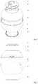
- FIG. 1represents a perspective view of the assembled bowl assembly
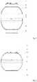
- FIG. 2represents a front view of the assembled bowl assembly
- FIG. 3represents an exploded perspective view of the bowl assembly
- FIG. 4represents an exploded front view of the bowl assembly
- FIG. 5represents a cross section through the exploded bowl assembly
- FIG. 6represents a cross-section through the assembled bowl assembly
- FIG. 7represents a detail of the protrusions located on the outside of the lower edge of the median extension, positioned diametrically opposed and at equal distances between them;
- FIG. 8represents a detail of the “L” shaped gripping grooves, profiled on the inside of the top edge of the main bowl, positioned diametrically opposed and at equal distances between them;
- FIG. 9represents a detail of the closing system, viewed from the front, in three sliding positions of the protrusion in the groove;
- FIG. 10represents a detail of the closing system viewed in the section
- FIG. 11represents details of the closing system, viewed from the front and in the section;
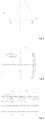
- FIG. 12represents a figure with the dimensional characteristics of the assembled bowl assembly
- FIG. 13represents an example of use.
- H1Total height of the bowl assembly (with the removable median extension attached) without the lid handle
- H2Height of lower bowl (base bowl)
- H3Height of the removable median extension+height of the lid without the lid handle
- the utility modelcomprises a spherical opaque plastic bowl ( 4 ) having a silicone sealant ( 5 ) applied to the bottom of the bowl to ensure the stability of the assembly during operation and which is provided at the top with four “L” shaped grooves, profiled on the inside of the top edge of the main bowl, positioned diametrically opposed and at equal distances between them ( 7 ), over which a removable median extension in the form of a spherical area open at its top and bottom ( 3 ) is attached, made of transparent plastic, which is provided with four protrusions diametrically opposed and at equal distances between them, located on the outside of the lower edge of the median extension ( 6 ).
- a plastic lid ( 2 )Above the removable extension a plastic lid ( 2 ) is positioned, which has a three-dimensional protruding grip profile ( 1 ) resulting from its configuration.
- the entire assemblyis characterized by the ratio of the H1 height of the bowl assembly to the D1 diameter of the sphere of the bowl assembly, H1/D1 in the range 0.8-0.9, the ratio of the H2 height of the bowl ( 4 ) to the H1 height of the bowl assembly, H2/H1 in the range 0.6-0.7, and the ratio of the H3 height of the median extension ( 3 ) to the H1 height of the bowl assembly, H3/H1 in the range 0.4-0.3.
- Closing between the parts of the bowl assemblyis achieved by a known gripping system, by sliding four protrusions ( 6 ) positioned diametrically opposed and at equal distances between them, located on the outside of the lower edge of the median extension, in four “L” shaped grooves ( 7 ), profiled on the inside of the top edge of the main bowl, positioned diametrically opposed and at equal distances between them.
- the joining of the parts together to form the bowl assemblyis illustrated in the details of FIGS. 9, 10, and 11 .
- the upper edge—the “lip”—of the bowl ( 4 ) and the lower edge of the spherical median extension ( 3 )have the special configurations shown in FIGS. 5, 7, and 8 , forming a known gripping system.
- the top edge of the bowl ( 4 )has four “L” shaped grooves ( 7 ) profiled on the inside, positioned diametrically opposed and at equal distances between them.
- the spherical median extension ( 3 )has on the outside of its lower edge four rounded protrusions ( 6 ) positioned diametrically opposed and at equal distances between them.
- the diameter of the four protrusions ( 6 )is smaller than the width of the grooves ( 7 ), and the joining of the spherical main bowl—the base of the assembly ( 4 ) and the spherical removable median extension ( 3 ) is achieved by sliding the four protrusions ( 6 ) into the four grooves ( 7 ) by a press-and-twist motion of the median extension ( 3 ) on the bowl ( 4 ).
- the various plastic elementscould be made of a heat-resistant plastic.
- the silicone sealantcould be a heat-resistant sealant.
Landscapes
- Engineering & Computer Science (AREA)
- Mechanical Engineering (AREA)
- Food Science & Technology (AREA)
- Food-Manufacturing Devices (AREA)
- Table Devices Or Equipment (AREA)
Abstract
Description
- 1. Lid gripping handle;
- 2. Plastic cover;
- 3. Median removable extension made of transparent plastic;
- 4. Opaque plastic bowl;
- 5. Silicone sealant;
- 6. Protrusions located on the outside of the lower edge of the median extension, positioned diametrically opposed and at equal distances between them; and
- 7. “L” shaped gripping grooves, profiled on the inside of the top edge of the main bowl, positioned diametrically opposed and at equal distances between them.
Claims (4)
Applications Claiming Priority (2)
| Application Number | Priority Date | Filing Date | Title |
|---|---|---|---|
| ROU201800030URO201800030U1 (en) | 2018-06-12 | 2018-06-12 | Bowl assembly |
| ROU201800030 | 2018-06-12 |
Publications (2)
| Publication Number | Publication Date |
|---|---|
| US20190375540A1 US20190375540A1 (en) | 2019-12-12 |
| US11046478B2true US11046478B2 (en) | 2021-06-29 |
Family
ID=66635687
Family Applications (1)
| Application Number | Title | Priority Date | Filing Date |
|---|---|---|---|
| US16/416,217Expired - Fee RelatedUS11046478B2 (en) | 2018-06-12 | 2019-05-18 | Mixing-bowl assembly |
Country Status (3)
| Country | Link |
|---|---|
| US (1) | US11046478B2 (en) |
| CN (1) | CN210871169U (en) |
| RO (1) | RO201800030U1 (en) |
Families Citing this family (1)
| Publication number | Priority date | Publication date | Assignee | Title |
|---|---|---|---|---|
| USD1087787S1 (en)* | 2023-09-29 | 2025-08-12 | 2Xl Corporation | Wipe dispenser |
Citations (20)
| Publication number | Priority date | Publication date | Assignee | Title |
|---|---|---|---|---|
| US133518A (en)* | 1872-12-03 | Improvement in fruit-jars | ||
| US3606074A (en)* | 1969-07-24 | 1971-09-20 | Robert M Hayes | Multiple purpose gripping lid |
| US4763568A (en)* | 1985-09-30 | 1988-08-16 | Kiczek Casimir R | Popcorn popper |
| DE9201599U1 (en) | 1992-02-05 | 1992-04-23 | HP Haushaltprodukte GmbH, 5430 Montabaur | Cooking vessel |
| US5169023A (en)* | 1991-09-04 | 1992-12-08 | Dart Industries Inc. | Tilting mixing bowl |
| US5893640A (en)* | 1997-07-11 | 1999-04-13 | Hamilton Beach/Proctor-Silex, Inc. | Food mixer with removable splash guard |
| US6123449A (en)* | 1998-10-26 | 2000-09-26 | Sadek-Patt; Arlene | Mixing bowl splatter guard |
| US20060248851A1 (en)* | 2005-02-03 | 2006-11-09 | Kishbaugh Ronald G | Glassware with silicone gripping surfaces |
| USD552473S1 (en)* | 2004-11-16 | 2007-10-09 | Reckitt Benckiser N.V. | Container |
| US20140061328A1 (en)* | 2012-08-30 | 2014-03-06 | American Covers, Inc. | Interchangable lid and base for air freshener |
| US20140099411A1 (en)* | 2012-10-10 | 2014-04-10 | Donald Lee Darnell | Method for quickly preparing a marshmallow based snack |
| US20150047511A1 (en)* | 2013-08-16 | 2015-02-19 | Focus Products Group International, Llc | Hot Air Popcorn Popper with Dual Wall Construction |
| WO2015153953A1 (en)* | 2014-04-03 | 2015-10-08 | Cata, Llc | Stackable drinkware |
| US20160021915A1 (en)* | 2014-07-24 | 2016-01-28 | Michael Wayne Baxter | Food storage container and methods of use |
| US20160060004A1 (en)* | 2013-11-26 | 2016-03-03 | Munchkin, Inc. | Multi-compartment container with flexible partition |
| WO2017217982A1 (en)* | 2016-06-15 | 2017-12-21 | Bemis Company, Inc. | Heat-seal lid with non-heat sealing layer and hydrophobic overcoat |
| US20180112337A1 (en)* | 2016-10-25 | 2018-04-26 | Kathleen Sullivan | Yarn-carrying and dispensing apparatus |
| US20180237188A1 (en)* | 2017-02-20 | 2018-08-23 | GBC Food Services, LLC | Compartmentalized hot liquid storage container |
| USRE48037E1 (en)* | 2013-07-11 | 2020-06-09 | Pepsico, Inc. | Cap and container |
| US20200207535A1 (en)* | 2018-12-28 | 2020-07-02 | Pepsico, Inc. | Beverage ingredient cartridge |
- 2018
- 2018-06-12ROROU201800030Upatent/RO201800030U1/enunknown
- 2019
- 2019-05-18USUS16/416,217patent/US11046478B2/ennot_activeExpired - Fee Related
- 2019-05-21CNCN201920730098.4Upatent/CN210871169U/ennot_activeExpired - Fee Related
Patent Citations (20)
| Publication number | Priority date | Publication date | Assignee | Title |
|---|---|---|---|---|
| US133518A (en)* | 1872-12-03 | Improvement in fruit-jars | ||
| US3606074A (en)* | 1969-07-24 | 1971-09-20 | Robert M Hayes | Multiple purpose gripping lid |
| US4763568A (en)* | 1985-09-30 | 1988-08-16 | Kiczek Casimir R | Popcorn popper |
| US5169023A (en)* | 1991-09-04 | 1992-12-08 | Dart Industries Inc. | Tilting mixing bowl |
| DE9201599U1 (en) | 1992-02-05 | 1992-04-23 | HP Haushaltprodukte GmbH, 5430 Montabaur | Cooking vessel |
| US5893640A (en)* | 1997-07-11 | 1999-04-13 | Hamilton Beach/Proctor-Silex, Inc. | Food mixer with removable splash guard |
| US6123449A (en)* | 1998-10-26 | 2000-09-26 | Sadek-Patt; Arlene | Mixing bowl splatter guard |
| USD552473S1 (en)* | 2004-11-16 | 2007-10-09 | Reckitt Benckiser N.V. | Container |
| US20060248851A1 (en)* | 2005-02-03 | 2006-11-09 | Kishbaugh Ronald G | Glassware with silicone gripping surfaces |
| US20140061328A1 (en)* | 2012-08-30 | 2014-03-06 | American Covers, Inc. | Interchangable lid and base for air freshener |
| US20140099411A1 (en)* | 2012-10-10 | 2014-04-10 | Donald Lee Darnell | Method for quickly preparing a marshmallow based snack |
| USRE48037E1 (en)* | 2013-07-11 | 2020-06-09 | Pepsico, Inc. | Cap and container |
| US20150047511A1 (en)* | 2013-08-16 | 2015-02-19 | Focus Products Group International, Llc | Hot Air Popcorn Popper with Dual Wall Construction |
| US20160060004A1 (en)* | 2013-11-26 | 2016-03-03 | Munchkin, Inc. | Multi-compartment container with flexible partition |
| WO2015153953A1 (en)* | 2014-04-03 | 2015-10-08 | Cata, Llc | Stackable drinkware |
| US20160021915A1 (en)* | 2014-07-24 | 2016-01-28 | Michael Wayne Baxter | Food storage container and methods of use |
| WO2017217982A1 (en)* | 2016-06-15 | 2017-12-21 | Bemis Company, Inc. | Heat-seal lid with non-heat sealing layer and hydrophobic overcoat |
| US20180112337A1 (en)* | 2016-10-25 | 2018-04-26 | Kathleen Sullivan | Yarn-carrying and dispensing apparatus |
| US20180237188A1 (en)* | 2017-02-20 | 2018-08-23 | GBC Food Services, LLC | Compartmentalized hot liquid storage container |
| US20200207535A1 (en)* | 2018-12-28 | 2020-07-02 | Pepsico, Inc. | Beverage ingredient cartridge |
Non-Patent Citations (2)
| Title |
|---|
| English machine translation of description and claims of DE 9201599 U1 (Apr. 23, 1992). |
| Search Report in related Romanian Patent Application No. U 2018 00030, dated Nov. 27, 2018. |
Also Published As
| Publication number | Publication date |
|---|---|
| RO201800030U1 (en) | 2019-05-30 |
| US20190375540A1 (en) | 2019-12-12 |
| CN210871169U (en) | 2020-06-30 |
Similar Documents
| Publication | Publication Date | Title |
|---|---|---|
| US8381640B1 (en) | Spaetzle preparation apparatus | |
| TW303339B (en) | ||
| US4892213A (en) | Microwave cooking and serving dish | |
| US20160066743A1 (en) | Cooking Pot with Straining Lid and Spoon Support | |
| US20240251987A1 (en) | Cookware Assembly | |
| US20200305644A1 (en) | Grease strainer for cooking apparatus | |
| US12035836B2 (en) | Cookware assembly | |
| US20070261568A1 (en) | Triangular frying pan | |
| US20140251890A1 (en) | Colander-bowl assembly | |
| US20140224810A1 (en) | Multi-Functional Flat Lid | |
| US6446544B1 (en) | Cooking utensil | |
| US5515990A (en) | Pot with tilt insert | |
| JP2015527143A (en) | Kitchen utensils placed in containers, kitchen utensils set with kitchen utensils and various functional units | |
| US11046478B2 (en) | Mixing-bowl assembly | |
| US9867503B2 (en) | Chopping system | |
| US20150001228A1 (en) | Spill Resistant Bowl | |
| US20200187699A1 (en) | Divided Cooking Device with a Lid | |
| US20170245684A1 (en) | Cooking Utensil With Divider System | |
| US6092689A (en) | Bowl with gripping means | |
| US20170303743A1 (en) | Cooking apparatus with strainer | |
| CA2625050A1 (en) | Measuring bowl having handle | |
| KR200318987Y1 (en) | Cooking receptacle | |
| KR200497121Y1 (en) | Ladle for cooking | |
| KR20150004092U (en) | A lid of vessel for cooking | |
| RU235330U1 (en) | Universal frying pan |
Legal Events
| Date | Code | Title | Description |
|---|---|---|---|
| FEPP | Fee payment procedure | Free format text:ENTITY STATUS SET TO UNDISCOUNTED (ORIGINAL EVENT CODE: BIG.); ENTITY STATUS OF PATENT OWNER: SMALL ENTITY | |
| FEPP | Fee payment procedure | Free format text:ENTITY STATUS SET TO SMALL (ORIGINAL EVENT CODE: SMAL); ENTITY STATUS OF PATENT OWNER: SMALL ENTITY | |
| STPP | Information on status: patent application and granting procedure in general | Free format text:DOCKETED NEW CASE - READY FOR EXAMINATION | |
| STPP | Information on status: patent application and granting procedure in general | Free format text:RESPONSE TO NON-FINAL OFFICE ACTION ENTERED AND FORWARDED TO EXAMINER | |
| STPP | Information on status: patent application and granting procedure in general | Free format text:FINAL REJECTION MAILED | |
| STPP | Information on status: patent application and granting procedure in general | Free format text:RESPONSE AFTER FINAL ACTION FORWARDED TO EXAMINER | |
| STPP | Information on status: patent application and granting procedure in general | Free format text:NOTICE OF ALLOWANCE MAILED -- APPLICATION RECEIVED IN OFFICE OF PUBLICATIONS | |
| AS | Assignment | Owner name:ANAMINA PLUS S.R.L., ROMANIA Free format text:ASSIGNMENT OF ASSIGNORS INTEREST;ASSIGNOR:DAVID, CARMEN BIANCA;REEL/FRAME:056192/0688 Effective date:20210412 | |
| STPP | Information on status: patent application and granting procedure in general | Free format text:PUBLICATIONS -- ISSUE FEE PAYMENT RECEIVED | |
| STPP | Information on status: patent application and granting procedure in general | Free format text:PUBLICATIONS -- ISSUE FEE PAYMENT VERIFIED | |
| STCF | Information on status: patent grant | Free format text:PATENTED CASE | |
| FEPP | Fee payment procedure | Free format text:MAINTENANCE FEE REMINDER MAILED (ORIGINAL EVENT CODE: REM.); ENTITY STATUS OF PATENT OWNER: SMALL ENTITY | |
| LAPS | Lapse for failure to pay maintenance fees | Free format text:PATENT EXPIRED FOR FAILURE TO PAY MAINTENANCE FEES (ORIGINAL EVENT CODE: EXP.); ENTITY STATUS OF PATENT OWNER: SMALL ENTITY | |
| STCH | Information on status: patent discontinuation | Free format text:PATENT EXPIRED DUE TO NONPAYMENT OF MAINTENANCE FEES UNDER 37 CFR 1.362 | |
| FP | Lapsed due to failure to pay maintenance fee | Effective date:20250629 |