US11046377B2 - Track system for traction of a vehicle - Google Patents
Track system for traction of a vehicleDownload PDFInfo
- Publication number
- US11046377B2 US11046377B2US15/724,733US201715724733AUS11046377B2US 11046377 B2US11046377 B2US 11046377B2US 201715724733 AUS201715724733 AUS 201715724733AUS 11046377 B2US11046377 B2US 11046377B2
- Authority
- US
- United States
- Prior art keywords
- track
- vehicle
- temperature
- traction
- temperature sensor
- Prior art date
- Legal status (The legal status is an assumption and is not a legal conclusion. Google has not performed a legal analysis and makes no representation as to the accuracy of the status listed.)
- Active
Links
Images


Classifications
- B—PERFORMING OPERATIONS; TRANSPORTING
- B62—LAND VEHICLES FOR TRAVELLING OTHERWISE THAN ON RAILS
- B62D—MOTOR VEHICLES; TRAILERS
- B62D55/00—Endless track vehicles
- B62D55/08—Endless track units; Parts thereof
- B62D55/18—Tracks
- B62D55/24—Tracks of continuously flexible type, e.g. rubber belts
- B62D55/244—Moulded in one piece, with either smooth surfaces or surfaces having projections, e.g. incorporating reinforcing elements
- B—PERFORMING OPERATIONS; TRANSPORTING
- B29—WORKING OF PLASTICS; WORKING OF SUBSTANCES IN A PLASTIC STATE IN GENERAL
- B29D—PRODUCING PARTICULAR ARTICLES FROM PLASTICS OR FROM SUBSTANCES IN A PLASTIC STATE
- B29D29/00—Producing belts or bands
- B—PERFORMING OPERATIONS; TRANSPORTING
- B60—VEHICLES IN GENERAL
- B60K—ARRANGEMENT OR MOUNTING OF PROPULSION UNITS OR OF TRANSMISSIONS IN VEHICLES; ARRANGEMENT OR MOUNTING OF PLURAL DIVERSE PRIME-MOVERS IN VEHICLES; AUXILIARY DRIVES FOR VEHICLES; INSTRUMENTATION OR DASHBOARDS FOR VEHICLES; ARRANGEMENTS IN CONNECTION WITH COOLING, AIR INTAKE, GAS EXHAUST OR FUEL SUPPLY OF PROPULSION UNITS IN VEHICLES
- B60K28/00—Safety devices for propulsion-unit control, specially adapted for, or arranged in, vehicles, e.g. preventing fuel supply or ignition in the event of potentially dangerous conditions
- B60K28/10—Safety devices for propulsion-unit control, specially adapted for, or arranged in, vehicles, e.g. preventing fuel supply or ignition in the event of potentially dangerous conditions responsive to conditions relating to the vehicle
- B—PERFORMING OPERATIONS; TRANSPORTING
- B60—VEHICLES IN GENERAL
- B60K—ARRANGEMENT OR MOUNTING OF PROPULSION UNITS OR OF TRANSMISSIONS IN VEHICLES; ARRANGEMENT OR MOUNTING OF PLURAL DIVERSE PRIME-MOVERS IN VEHICLES; AUXILIARY DRIVES FOR VEHICLES; INSTRUMENTATION OR DASHBOARDS FOR VEHICLES; ARRANGEMENTS IN CONNECTION WITH COOLING, AIR INTAKE, GAS EXHAUST OR FUEL SUPPLY OF PROPULSION UNITS IN VEHICLES
- B60K35/00—Instruments specially adapted for vehicles; Arrangement of instruments in or on vehicles
- B60K35/10—Input arrangements, i.e. from user to vehicle, associated with vehicle functions or specially adapted therefor
- B—PERFORMING OPERATIONS; TRANSPORTING
- B60—VEHICLES IN GENERAL
- B60K—ARRANGEMENT OR MOUNTING OF PROPULSION UNITS OR OF TRANSMISSIONS IN VEHICLES; ARRANGEMENT OR MOUNTING OF PLURAL DIVERSE PRIME-MOVERS IN VEHICLES; AUXILIARY DRIVES FOR VEHICLES; INSTRUMENTATION OR DASHBOARDS FOR VEHICLES; ARRANGEMENTS IN CONNECTION WITH COOLING, AIR INTAKE, GAS EXHAUST OR FUEL SUPPLY OF PROPULSION UNITS IN VEHICLES
- B60K35/00—Instruments specially adapted for vehicles; Arrangement of instruments in or on vehicles
- B60K35/20—Output arrangements, i.e. from vehicle to user, associated with vehicle functions or specially adapted therefor
- B60K35/21—Output arrangements, i.e. from vehicle to user, associated with vehicle functions or specially adapted therefor using visual output, e.g. blinking lights or matrix displays
- B60K35/22—Display screens
- G—PHYSICS
- G07—CHECKING-DEVICES
- G07C—TIME OR ATTENDANCE REGISTERS; REGISTERING OR INDICATING THE WORKING OF MACHINES; GENERATING RANDOM NUMBERS; VOTING OR LOTTERY APPARATUS; ARRANGEMENTS, SYSTEMS OR APPARATUS FOR CHECKING NOT PROVIDED FOR ELSEWHERE
- G07C5/00—Registering or indicating the working of vehicles
- G07C5/08—Registering or indicating performance data other than driving, working, idle, or waiting time, with or without registering driving, working, idle or waiting time
- G07C5/0808—Diagnosing performance data
- G—PHYSICS
- G07—CHECKING-DEVICES
- G07C—TIME OR ATTENDANCE REGISTERS; REGISTERING OR INDICATING THE WORKING OF MACHINES; GENERATING RANDOM NUMBERS; VOTING OR LOTTERY APPARATUS; ARRANGEMENTS, SYSTEMS OR APPARATUS FOR CHECKING NOT PROVIDED FOR ELSEWHERE
- G07C5/00—Registering or indicating the working of vehicles
- G07C5/08—Registering or indicating performance data other than driving, working, idle, or waiting time, with or without registering driving, working, idle or waiting time
- G07C5/0816—Indicating performance data, e.g. occurrence of a malfunction
- G07C5/0825—Indicating performance data, e.g. occurrence of a malfunction using optical means
- B—PERFORMING OPERATIONS; TRANSPORTING
- B29—WORKING OF PLASTICS; WORKING OF SUBSTANCES IN A PLASTIC STATE IN GENERAL
- B29K—INDEXING SCHEME ASSOCIATED WITH SUBCLASSES B29B, B29C OR B29D, RELATING TO MOULDING MATERIALS OR TO MATERIALS FOR MOULDS, REINFORCEMENTS, FILLERS OR PREFORMED PARTS, e.g. INSERTS
- B29K2995/00—Properties of moulding materials, reinforcements, fillers, preformed parts or moulds
- B29K2995/0037—Other properties
- B29K2995/0087—Wear resistance
- B—PERFORMING OPERATIONS; TRANSPORTING
- B29—WORKING OF PLASTICS; WORKING OF SUBSTANCES IN A PLASTIC STATE IN GENERAL
- B29L—INDEXING SCHEME ASSOCIATED WITH SUBCLASS B29C, RELATING TO PARTICULAR ARTICLES
- B29L2029/00—Belts or bands
Definitions
- the inventionrelates to track systems for traction of off-road vehicles such as, for example, agricultural vehicles, industrial vehicles, and military vehicles.
- Certain off-road vehiclessuch as agricultural vehicles (e.g., harvesters, combines, tractors, etc.), industrial vehicles such as construction vehicles (e.g., loaders, bulldozers, excavators, etc.) and forestry vehicles (e.g., feller-bunchers, tree chippers, knuckleboom loaders, etc.), and military vehicles (e.g., combat engineering vehicles (CEVs), etc.) to name a few, may be equipped with elastomeric tracks which enhance their traction and floatation on soft, slippery and/or irregular grounds (e.g., soil, mud, sand, ice, snow, etc.) on which they operate.
- agricultural vehiclese.g., harvesters, combines, tractors, etc.
- industrial vehiclessuch as construction vehicles (e.g., loaders, bulldozers, excavators, etc.) and forestry vehicles (e.g., feller-bunchers, tree chippers, knuckleboom loaders, etc
- An elastomeric trackcomprises a ground-engaging outer side including a plurality of traction projections, sometimes referred to as “traction lugs”, “tread bars” or “tread blocks”, which are distributed in its longitudinal direction to enhance traction on the ground. Deterioration of the traction projections during use may sometimes become significant enough to force replacement of the track even though the track's carcass is still in acceptable condition. For example, the traction projections may sometimes “blowout”, i.e., explode, under repeated loads as heat buildup within them increases their internal temperature such that part of their internal elastomeric material decomposes and generates a volatile product which increases internal pressure until they burst.
- the traction projectionsmay wear rapidly in some cases (e.g., due to abrasive or harsh ground conditions). Such deterioration of the traction projections may become more prominent, particularly where there is more roading of the track on hard road surfaces (e.g., in an agricultural vehicle travelling on paved roads between fields or other agricultural sites).
- This type of trackalso comprises an inner side which may include a plurality of drive/guide projections, commonly referred to as “drive/guide lugs”, which are spaced apart along its longitudinal direction and used for driving and/or guiding the track around wheels of a vehicle to which the track provides traction. Wear or other deterioration of the drive/guide lugs (e.g., as they come into contact with one or more of the wheels) often also reduces the track's useful life.
- a track for traction of a vehicleis mountable around a plurality of wheels that comprises a drive wheel for driving the track.
- the trackis elastomeric to flex around the wheels.
- the trackcomprises: an inner surface for facing the wheels; a ground-engaging outer surface for engaging the ground; and a plurality of traction projections projecting from the ground-engaging outer surface and distributed in a longitudinal direction of the track.
- Each traction projection of the plurality of traction projectionscomprises a first material and a second material disposed inwardly of the first material. A blowout resistance of the second material is greater than a blowout resistance of the first material.
- a track for traction of a vehicleis mountable around a plurality of wheels that comprises a drive wheel for driving the track.
- the trackis elastomeric to flex around the wheels.
- the trackcomprises: an inner surface for facing the wheels; a ground-engaging outer surface for engaging the ground; and a plurality of traction projections projecting from the ground-engaging outer surface and distributed in a longitudinal direction of the track.
- Each traction projection of the plurality of traction projectionshas a blowout time of at least 15 minutes under ASTM D-623 (method A) conditions.
- a method of making a track for traction of a vehiclecomprising a track.
- the trackis mountable around a plurality of wheels that comprises a drive wheel for driving the track.
- the trackis elastomeric to flex around the wheels.
- the methodcomprises forming a body of the track.
- the bodycomprises an inner surface for facing the wheels and a ground-engaging outer surface for engaging the ground.
- the methodcomprises forming a plurality of traction projections projecting from the ground-engaging outer surface and distributed in a longitudinal direction of the track.
- Each traction projection of the plurality of traction projectionscomprises a first material and a second material disposed inwardly of the first material.
- a blowout resistance of the second materialis greater than a blowout resistance of the first material.
- a method of making a track for traction of a vehiclecomprising a track.
- the trackis mountable around a plurality of wheels that comprises a drive wheel for driving the track.
- the trackis elastomeric to flex around the wheels.
- the methodcomprises forming a body of the track.
- the bodycomprises an inner surface for facing the wheels and a ground-engaging outer surface for engaging the ground.
- the methodcomprises forming a plurality of traction projections projecting from the ground-engaging outer surface and distributed in a longitudinal direction of the track.
- Each traction projection of the plurality of traction projectionshas a blowout time of at least 15 minutes under ASTM D-623 (Method A) conditions.
- a system for protecting a track providing traction to a vehiclecomprising: a plurality of wheels that comprises a drive wheel for driving the track.
- the trackis elastomeric to flex around the wheels.
- the trackcomprises: an inner surface for facing the wheels; a ground-engaging outer surface for engaging the ground; and a plurality of traction projections projecting from the ground-engaging outer surface and distributed in a longitudinal direction of the track.
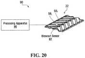
- the systemcomprises: a sensor for monitoring the track; and a processing apparatus connected to the sensor and configured to issue a signal regarding a potential occurrence of blowout of at least one of the traction projections.
- FIG. 1shows an example of a tracked vehicle comprising a track system in accordance with an embodiment of the invention
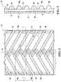
- FIGS. 2 and 3show a plan view and a side view of a track of the track system
- FIG. 4shows an inside view of the track
- FIG. 5shows a cross-sectional view of the track
- FIG. 6shows a perspective view of traction projection of the track
- FIG. 7shows a drive wheel of a track-engaging assembly of the track system
- FIG. 8shows a drive/guide projection of the track
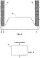
- FIG. 9shows an example of a test to measure a blowout resistance of a traction projection of the track
- FIG. 10shows zones of different materials of a traction projection of the track
- FIG. 11shows an example of an embodiment of a traction projection of the track that comprises two zones of different materials varying in blowout resistance and wear resistance;
- FIG. 12shows another example of an embodiment of a traction projection of the track that comprises multiple layered zones of different materials varying in blowout resistance and wear resistance;
- FIG. 13Ashows a graph representing a variation in blowout resistance in relation to a distance within the traction projection of FIG. 12 ;
- FIG. 13Bshows a graph representing a variation in wear resistance in relation to a distance within the traction projection of FIG. 12 ;
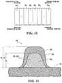
- FIG. 14shows another example of an embodiment of a traction projection of the track that comprises zones of different materials with different thicknesses
- FIG. 15Ashows a graph representing a variation in blowout resistance along the traction projection of FIG. 14 ;
- FIG. 15Bshows a graph representing a variation in wear resistance across the traction projection of FIG. 14 ;
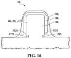
- FIG. 16shows another example of an embodiment of a traction projection of the track that comprises zones of different materials that are mechanically interlocked
- FIG. 17shows another example of an embodiment of a traction projection of the track that comprises zones of different materials that vary in blowout resistance and wear resistance;
- FIG. 18Ashows a graph representing a variation in blowout resistance along the traction projection of FIG. 17 ;
- FIG. 18Bshows a graph representing a variation in wear resistance along the traction projection of FIG. 17 ;
- FIG. 19shows another example of an embodiment of a traction projection of the track that comprises zones of different materials that vary in blowout resistance and wear resistance;
- FIG. 20shows an example of an embodiment of a blowout protection system of the tracked vehicle, comprising a processing apparatus and a blowout sensor;
- FIG. 21shows an example of an embodiment in which the blowout sensor is incorporated in the track
- FIG. 22shows an example of an embodiment of the processing apparatus
- FIG. 23shows an example of implementation in which the processing apparatus interacts with an output device
- FIG. 24shows an example of an embodiment in which the output device comprises a display
- FIG. 25shows an example of an embodiment in which the output device comprises a speaker
- FIG. 26shows a connection between the processing apparatus and a prime mover of the tracked vehicle.
- FIG. 27shows an example of a drive/guide projection of the track that comprises zones of different materials varying in blowout resistance and wear resistance, in accordance with another embodiment of the invention.
- FIG. 1shows an example of an off-road tracked vehicle 10 in accordance with an embodiment of the invention.
- the vehicle 10is a heavy-duty work vehicle for performing agricultural work, construction or other industrial work, or military work. More particularly, in this embodiment, the vehicle 10 is an agricultural vehicle for performing agricultural work. Specifically, in this example, the agricultural vehicle 10 is a tractor. In other examples, the agricultural vehicle 10 may be a combine harvester, another type of harvester, or any other type of agricultural vehicle.
- the agricultural vehicle 10comprises a frame 12 supporting a prime mover 14 , a pair of track systems 16 1 , 16 2 (which can be referred to as “undercarriages”), and an operator cabin 20 , which enable an operator to move the agricultural vehicle 10 on the ground to perform agricultural work possibly using a work implement 18 .
- the prime mover 14provides motive power to move the agricultural vehicle 10 .
- the prime mover 14may comprise an internal combustion engine and/or one or more other types of motors (e.g., electric motors, etc.) for generating motive power to move the agricultural vehicle 10 .
- the prime mover 14is in a driving relationship with each of the track systems 16 1 , 16 2 . That is, power derived from the prime mover 14 is transmitted to the track systems 16 1 , 16 2 via a powertrain of the agricultural vehicle 10 .
- the work implement 18is used to perform agricultural work.
- the work implement 18may be a combine head, a cutter, a scraper, a tiller, or any other type of agricultural work implement.
- the operator cabin 20is where the operator sits and controls the agricultural vehicle 10 . More particularly, the operator cabin 20 comprises a user interface including a set of controls that allow the operator to steer the agricultural vehicle 10 on the ground and operate the work implement 18 .
- Each track system 16 icomprises a track-engaging assembly 21 and a track 22 disposed around the track-engaging assembly 21 .
- the track-engaging assembly 21comprises a plurality of wheels which, in this example, includes a drive wheel 24 and a plurality of idler wheels that includes a front idler wheel 26 and a plurality of roller wheels 28 1 - 28 6 .
- the track system 16 ialso comprises a frame 13 which supports various components of the track system 16 i , including the roller wheels 28 1 - 28 6 .
- the track system 16 ihas a longitudinal direction and a first longitudinal end 57 and a second longitudinal end 59 that define a length of the track system 16 i .
- the track system 16 ihas a widthwise direction and a width that is defined by a width of the track 22 .
- the track system 16 ialso has a height direction that is normal to its longitudinal direction and its widthwise direction.
- the track 22engages the ground to provide traction to the agricultural vehicle 10 .
- certain parts of the track 22are designed to enhance their resistance to deterioration during use, including their resistance to blowout, as further discussed later.
- a length of the track 22allows the track 22 to be mounted around the track-engaging assembly 21 .
- the track 22can be referred to as an “endless” track.
- the track 22comprises an inner side 45 , a ground-engaging outer side 47 , and lateral edges 49 1 , 49 2 .
- the inner side 45faces the wheels 24 , 26 , 28 1 - 28 6 , while the ground-engaging outer side 47 engages the ground.
- a top run 65 of the track 22extends between the longitudinal ends 57 , 59 of the track system 16 i and over the wheels 24 , 26 , 28 1 - 28 6
- a bottom run 66 of the track 22extends between the longitudinal ends 57 , 59 of the track system 16 i and under the wheels 24 , 26 , 28 1 - 28 6
- the track 22has a longitudinal axis 19 which defines a longitudinal direction of the track 22 (i.e., a direction generally parallel to its longitudinal axis) and transversal directions of the track 22 (i.e., directions transverse to its longitudinal axis), including a widthwise direction of the track 22 (i.e., a lateral direction generally perpendicular to its longitudinal axis).
- the track 22has a thickness direction normal to its longitudinal and widthwise directions.
- the track 22is elastomeric, i.e., comprises elastomeric material, to be flexible around the track-engaging assembly 21 .
- the elastomeric material of the track 22can include any polymeric material with suitable elasticity.
- the elastomeric material of the track 22includes rubber.
- Various rubber compoundsmay be used and, in some cases, different rubber compounds may be present in different areas of the track 22 .
- the elastomeric material of the track 22may include another elastomer in addition to or instead of rubber (e.g., polyurethane elastomer).
- the track 22comprises an endless body 36 underlying its inner side 45 and ground-engaging outer side 47 .
- the body 36will be referred to as a “carcass”.
- the carcass 36is elastomeric in that it comprises elastomeric material 38 which allows the carcass 36 to elastically change in shape and thus the track 22 to flex as it is in motion around the track-engaging assembly 21 .
- the carcass 36comprises an inner surface 32 and a ground-engaging outer surface 31 that are opposite one another.
- the carcass 36comprises a plurality of reinforcements embedded in its elastomeric material 38 .
- These reinforcementscan take on various forms.
- the carcass 36comprises a layer of reinforcing cables 37 1 - 37 M that are adjacent to one another and extend generally in the longitudinal direction of the track 22 to enhance strength in tension of the track 22 along its longitudinal direction.
- each of the reinforcing cables 37 1 - 37 Mis a cord including a plurality of strands (e.g., textile fibers or metallic wires).
- each of the reinforcing cables 37 1 - 37 Mmay be another type of cable and may be made of any material suitably flexible along the cable's longitudinal axis (e.g., fibers or wires of metal, plastic or composite material).
- the carcass 36comprises a layer of reinforcing fabric 43 .
- the reinforcing fabric 43comprises thin pliable material made usually by weaving, felting, knitting, interlacing, or otherwise crossing natural or synthetic elongated fabric elements, such as fibers, filaments, strands and/or others, such that some elongated fabric elements extend transversally to the longitudinal direction of the track 22 to have a reinforcing effect in a transversal direction of the track 22 .
- the reinforcing fabric 43may comprise a ply of reinforcing woven fibers (e.g., nylon fibers or other synthetic fibers).
- the carcass 36has a thickness T c , measured from its inner surface 32 to its ground-engaging outer surface 31 , which is relatively large in this embodiment.
- the thickness T c of the carcass 36may be at least than 20 mm, in some cases at least 25 mm, in some cases at least 30 mm, in some cases at least 35 mm, and in some cases even more (e.g., 40 mm or more).
- the thickness T c of the carcass 36may have any other suitable value in other embodiments.
- the carcass 36may be molded into shape in a molding process during which the rubber 38 is cured.
- a moldmay be used to consolidate layers of rubber providing the rubber 38 of the carcass 36 , the reinforcing cables 37 1 - 37 M and the layer of reinforcing fabric 43 .
- the endless track 22is a one-piece “jointless” track such that the carcass 36 is a one-piece jointless carcass.
- the endless track 22may be a “jointed” track (i.e., having at least one joint connecting adjacent parts of the track 22 ) such that the carcass 36 is a jointed carcass (i.e., which has adjacent parts connected by the at least one joint).
- the track 22may comprise a plurality of track sections interconnected to one another at a plurality of joints, in which case each of these track sections includes a respective part of the carcass 36 .
- the endless track 22may be a one-piece track that can be closed like a belt with connectors at both of its longitudinal ends to form a joint.
- the inner side 45 of the endless track 22comprises an inner surface 55 of the carcass 36 and a plurality of inner wheel-contacting projections 48 1 - 48 N that project from the inner surface 55 and are positioned to contact at least some of the wheels 24 , 26 , 28 1 - 28 6 to do at least one of driving (i.e., imparting motion to) the track 22 and guiding the track 22 .
- the wheel-contacting projections 48 1 - 48 Ncan be referred to as “wheel-contacting lugs”.
- the wheel-contacting lugs 48 1 - 48 Ncan be referred to as “drive/guide projections” or “drive/guide lugs”.
- a drive/guide lug 48 imay interact with the drive wheel 24 to drive the track 22 , in which case the drive/guide lug 48 i is a drive lug.
- a drive/guide lug 48 imay interact with the idler wheel 26 and/or the roller wheels 28 1 - 28 6 to guide the track 22 to maintain proper track alignment and prevent de-tracking without being used to drive the track 22 , in which case the drive/guide lug 48 i is a guide lug.
- a drive/guide lug 48 imay both (i) interact with the drive wheel 24 to drive the track and (ii) interact with the idler wheel 26 and/or the roller wheels 28 1 - 28 6 to guide the track 22 to maintain proper track alignment and prevent de-tracking, in which case the drive/guide lug 48 i is both a drive lug and a guide lug.
- the drive/guide lugs 48 1 - 48 Ninteract with the drive wheel 24 in order to cause the track 22 to be driven, and also interact with the idler wheel 26 and the roller wheels 28 1 - 28 6 in order to guide the track 22 as it is driven by the drive wheel 24 to maintain proper track alignment and prevent de-tracking.
- the drive/guide lugs 48 1 - 48 Nare thus used to both drive the track 22 and guide the track 22 in this embodiment.
- the drive/guide lugs 48 1 - 48 Nare arranged in a single row disposed longitudinally along the inner side 45 of the track 22 .
- the drive/guide lugs 48 1 - 48 Nmay be arranged in other manners in other examples of implementation (e.g., in a plurality of rows that are spaced apart along the widthwise direction of the track 22 ).
- each drive/guide lug 48 iis an elastomeric drive/guide lug in that it comprises elastomeric material 67 .
- the elastomeric material 67can be any polymeric material with suitable elasticity. More particularly, in this embodiment, the elastomeric material 67 includes rubber. Various rubber compounds may be used and, in some cases, different rubber compounds may be present in different areas of the drive/guide lug 48 i . In other embodiments, the elastomeric material 67 may include another elastomer in addition to or instead of rubber (e.g., polyurethane elastomer).
- the drive/guide lugs 48 1 - 48 Nmay be provided on the inner side 45 in various ways. For example, in this embodiment, the drive/guide lugs 48 1 - 48 N are provided on the inner side 45 by being molded with the carcass 36 .
- the ground-engaging outer side 47comprises a ground-engaging outer surface 75 of the carcass 36 and a tread pattern 40 to enhance traction on the ground.
- the tread pattern 40comprises a plurality of traction projections 58 1 - 58 T projecting from the ground-engaging outer surface 75 , spaced apart in the longitudinal direction of the endless track 22 and engaging the ground to enhance traction.
- the traction projections 58 1 - 58 Tmay be referred to as “tread projections” or “traction lugs”.
- the traction lugs 58 1 - 58 Tmay have any suitable shape.
- each of the traction lugs 58 1 - 58 Thas an elongated shape and is angled, i.e., defines an oblique angle ⁇ (i.e., an angle that is not a right angle or a multiple of a right angle), relative to the longitudinal direction of the track 22 .
- the traction lugs 58 1 - 58 Tmay have various other shapes in other examples (e.g., curved shapes, shapes with straight parts and curved parts, etc.).
- each traction lug 58 ihas a periphery 69 which includes a front surface 80 1 , a rear surface 80 2 , two side surfaces 81 1 , 81 2 , and a top surface 86 .
- the front surface 80 1 and the rear surface 80 2are opposed to one another in the longitudinal direction of the track 22 .
- the two side faces 81 1 , 81 2are opposed to one another in the widthwise direction of the track 22 .
- the front surface 80 1 , the rear surface 80 2 , and the side surfaces 81 1 , 81 2are substantially straight.
- the periphery 69 of the traction lug 58 imay have any other shape in other embodiments (e.g., the front surface 80 1 , the rear surface 80 2 , and/or the side surfaces 81 1 , 81 2 may be curved).
- the traction lug 58 ihas a front-to-rear dimension L L in the longitudinal direction of the track 22 , a side-to-side dimension L W in the widthwise direction of the track 22 , and a height H in the thickness direction of the track 22 .
- each traction lug 58 iis an elastomeric traction lug in that it comprises elastomeric material 41 .
- the elastomeric material 41can be any polymeric material with suitable elasticity. More particularly, in this embodiment, the elastomeric material 41 includes rubber. Various rubber compounds may be used and, in some cases, different rubber compounds may be present in different areas of the traction lug 58 i . In other embodiments, the elastomeric material 41 may include another elastomer in addition to or instead of rubber (e.g., polyurethane elastomer).
- the traction lugs 58 1 - 58 Tmay be provided on the ground-engaging outer side 27 in various ways. For example, in this embodiment, the traction lugs 58 1 - 58 T are provided on the ground-engaging outer side 27 by being molded with the carcass 36 .
- the track 22may be constructed in various other manners in other embodiments.
- the track 22may have recesses or holes that interact with the drive wheel 24 in order to cause the track 22 to be driven (e.g., in which case the drive/guide lugs 48 1 - 48 N may be used only to guide the track 22 without being used to drive the track 22 , i.e., they may be “guide lugs” only), and/or the ground-engaging outer side 47 of the track 22 may comprise various patterns of traction lugs.
- the drive wheel 24is rotatable by power derived from the prime mover 14 to drive the track 22 . That is, power generated by the prime mover 14 and delivered over the powertrain of the agricultural vehicle 10 can rotate a driven axle, which causes rotation of the drive wheel 24 , which in turn imparts motion to the track 22 .
- the drive wheel 24comprises a drive sprocket comprising a plurality of drive members 52 1 - 52 B spaced apart along a circular path to engage the drive/guide lugs 48 1 - 48 N of the track 22 in order to drive the track 22 .
- the drive wheel 24 and the track 22thus implement a “positive drive” system.
- the drive wheel 24comprises two side discs 50 1 , 50 2 which are co-centric and turn about a common axle 51 and between which the drive members 52 1 - 52 B extend near respective peripheries of the side discs 50 1 , 50 2 .
- the drive members 52 1 - 52 Bare thus drive bars that extend between the side discs 50 1 , 50 2 .
- the drive wheel 24 and the track 22have respective dimensions allowing interlocking of the drive bars 52 1 - 52 B of the drive wheel 24 and the drive/guide lugs 48 1 - 48 N of the track 22 .
- Adjacent ones of the drive bars 52 1 - 52 Bdefine an interior space 53 between them to receive one of the drive/guide lugs 48 1 - 48 N .
- Adjacent ones of the drive/guide lugs 48 1 - 48 Ndefine an inter-lug space 39 between them to receive one of the drive bars 52 1 - 52 B .
- the drive/guide lugs 48 1 - 48 N and the drive bars 52 1 - 52 Bhave a regular spacing that allows interlocking of the drive/guide lugs 48 1 - 48 N and the drive bars 52 1 - 52 B over a certain length of the drive wheel's circumference.
- the drive wheel 24may be configured in various other ways in other embodiments.
- the drive wheel 24may not have any side discs such as the side discs 50 1 , 50 2 .
- the drive members 52 1 - 52 Bmay be drive teeth that are distributed circumferentially along the drive wheel 24 or any other type of drive members.
- the drive wheel 24may have teeth that enter these recesses or holes in order to drive the track 22 .
- the drive wheel 24may frictionally engage the inner side 45 of the track 22 in order to frictionally drive the track 22 (i.e., the drive wheel 24 and the track 22 may implement a “friction drive” system).
- the front idler wheel 26 and the roller wheels 28 1 - 28 6are not driven by power supplied by the prime mover 14 , but are rather used to do at least one of supporting part of the weight of the agricultural vehicle 10 on the ground via the track 22 , guiding the track 22 as it is driven by the drive wheel 24 , and tensioning the track 22 .
- the front idler wheel 26is a leading idler wheel which maintains the track 22 in tension and helps to support part of the weight of the agricultural vehicle 10 on the ground via the track 22 .
- the roller wheels 28 1 - 28 6roll on a rolling path 33 of the inner side 45 of the track 22 along the bottom run 66 of the track 22 to apply the bottom run 66 on the ground.
- the roller wheels 28 1 - 28 6can be referred to as “mid-rollers”.
- the traction lugs 58 1 - 58 Tcan be designed to enhance their resistance to deterioration during use.
- a blowout resistance of each traction lug 58 ican be enhanced to prevent or at least reduce a potential for blowout of the traction lug 58 i under repeated loads which may induce heat buildup within it.
- a wear resistance of the traction lug 58 imay be enhanced such that the traction lug 58 i wears less rapidly. This enhanced resistance to deterioration of the traction lugs 58 1 - 58 T may be particularly useful in situations where the track 22 experiences significant roading on hard road surfaces, such as, for example, when the agricultural vehicle 10 travels on paved roads between fields or other agricultural sites.
- the blowout resistance of a traction lug 58 iis greater than a threshold.
- a testmay be performed to measure the blowout resistance of the traction lug 58 i .
- a sample of the traction lug 58 i of specified dimensionscan be repeatedly compressed at a specified frequency by applying a load causing a specified deformation (e.g., compression) and measuring one or more parameters indicative of the blowout resistance of the traction lug 58 i .
- the testmay be a standard test.
- the blowout resistance of the traction lug 58 imay be measured under ASTM D-623 (Method A) conditions (e.g., sample dimensions, load, frequency and deformation specified by ASTM D-623).
- a sample of the traction lug 58 i of specified dimensionscan be taken from the traction lug 58 i , subjected to a specified preload (i.e., 110 lbs), conditioned at a specified temperature (i.e., 100° C.) for a specified period of time (i.e., 25 minutes), and repeatedly compressed by causing a specified deformation (e.g., compression) (i.e., 0.250 inches in amplitude) at a specified frequency (i.e., 30 Hz) in order to measure one or more parameters indicative of the blowout resistance of the traction lug 58 i .
- a specified preloadi.e., 110 lbs
- conditioned at a specified temperaturei.e., 100° C.
- a specified period of timei.e., 25 minutes
- a specified deformationi.e., compression
- a specified frequencyi.e., 30 Hz
- blowout time B of the sample of the traction lug 58 i and/or the blowout temperature T b of the sample of the traction lug 58 imay have any other suitable value in other examples of implementation.
- the wear resistance of a traction lug 58 iis greater than a threshold.
- the wear resistance of the traction lug 58 imay be expressed as an abrasion resistance of the traction lug 58 i .
- a testmay be performed to measure the wear resistance of the traction lug 58 i .
- a sample of the traction lug 58 i of specified dimensionscan be moved across a surface of an abrasive sheet mounted to a revolving drum to measure the wear of the traction lug 58 i as a volume loss in cubic millimeters or an abrasion resistance index in percent.
- the testmay be a standard test.
- the wear resistance of the traction lug 58 iexpressed as its abrasion resistance, may be measured under ASTM D-5963 conditions (e.g., sample dimensions; loading conditions; etc.).
- a sample of the traction lug 58 i of dimensions specified by ASTM D-5963can be taken from the traction lug 58 i and moved against a surface of an abrasive sheet mounted to a revolving drum as specified by ASTM D-5963 and measuring one or more parameters indicative of the abrasion resistance of the traction lug 58 i .
- a volume loss in cubic millimeters of the sample of the traction lug 58 imay be no more than 110 mm 3 , in some cases no more than 100 mm 3 , more than 90 mm 3 , in some cases no more than 80 mm 3 , and in some cases even less (e.g., no more than 70 mm 3 or 60 mm 3 ).
- the volumetric loss of the sample of the traction lug 58 imay have any other suitable value in other examples of implementation.
- Enhancement of the resistance to deterioration of the traction lugs 58 1 - 58 Tmay be achieved in various ways in various embodiments.
- each traction lug 58 iis characterized by a material distribution profile to enhance its resistance to deterioration, including its blowout resistance and its wear resistance.
- the material distribution profileis designed such that the traction lug 58 i has a material composition defining an arrangement of zones of different materials 60 i - 60 Z .
- These different materials 60 1 - 60 Zbelong to different classes of materials (i.e., polymers, metals, ceramics and composites) and/or exhibit substantially different values of a given material property (e.g., a modulus of elasticity, tensile strength, hardness, friction coefficient, crack growth resistance, etc.).
- the arrangement of zones of different materials 60 1 - 60 Zis designed into the traction lug 58 i . That is, the arrangement of zones of different materials 60 1 - 60 Z does not occur by chance (e.g., during manufacturing or use of the traction lug 58 i ), but is rather achieved by a careful material selection and distribution within the traction lug 58 i during design of the track 22 .
- the arrangement of zones of different materials 60 1 - 60 Zmay comprise two, three, four, five or more zones of different materials. Also, while the arrangement of zones of different materials 60 1 - 60 Z may comprise any selection of different materials, in some embodiments, the arrangement of zones of different materials 60 1 - 60 Z may comprise a plurality of zones of different elastomeric materials (i.e., two, three, four, five or more zones of different elastomeric materials). For example, such different elastomeric materials may include different rubbers, thermoplastic elastomers (TPE) such as polyurethane elastomers, and/or other elastomers.
- TPEthermoplastic elastomers
- the zones of different materials 60 1 - 60 Zmay be provided in any suitable way using one or more manufacturing processes, such as, for example, a molding process (e.g., an injection molding process, a compression molding process, etc.), an extrusion process (e.g., a coextrusion process), a pouring process, a gluing process, a coating process, a heat treatment, a penetrating treatment (e.g., an electromagnetic radiation treatment, etc.), and/or any other suitable manufacturing process. Examples of how the zones of different materials 60 1 - 60 Z may be provided in various embodiments are discussed below.
- the arrangement of zones of different materials 60 1 - 60 Zis configured such that the traction lug 58 i exhibits a desired variation in blowout resistance across the arrangement of zones of different materials 60 1 - 60 Z . Also, in this embodiment, the arrangement of zones of different materials 60 1 - 60 Z is configured such that the traction lug 58 i exhibits a desired variation in wear resistance across the arrangement of zones of different materials 60 1 - 60 Z .
- each of these variationsis “desired” in that it is designed into the traction lug 58 i by the careful material selection and distribution within the traction lug 58 i to create the arrangement of zones of different materials 60 1 - 60 Z during design of the track 22 such that the blowout resistance and the wear resistance vary in an intended manner.
- these desired variationscan also be referred to as a “selected”, “predetermined”, “intended” or “controlled” variation in blowout resistance and wear resistance.
- the blowout resistanceincreases inwardly, i.e., in a direction away from the periphery 69 of the traction lug 58 i towards an inside of the traction lug 58 i .
- the blowout resistance of an inner material 60 x of the traction lug 58 iis greater than the blowout resistance of an outer material 60 y of the traction lug 58 i .
- the inner material 60 x and the outer material 60 yare respectively referred to as being “inner” and “outer” in that the inner material 60 x is disposed inwardly of the outer material 60 y , i.e., the outer material 60 y is disposed between the inner material 60 x and the periphery 69 of the traction lug 58 i (e.g., and may extend to the periphery 69 of the traction lug 58 i ).
- the outer material 60 yis thus closer to the periphery 69 of the traction lug 58 i than the inner material 60 x (e.g., and may extend to the periphery 69 of the traction lug 58 i ).
- the blowout resistance of the inner material 60 x of the traction lug 58 imay be measured by subjecting a sample of the inner material 60 x to a test as described above and measuring one or more parameters indicative of its blowout resistance, such as the blowout temperature T b of the sample of the inner material 60 x and/or the blowout time B of the sample of the inner material 60 x .
- a similar proceduremay be followed for measuring the blowout resistance of the outer material 60 y of the traction lug 58 i .
- the wear resistanceincreases outwardly, i.e., in a direction towards the periphery 69 of the traction lug 58 i . More particularly, in this example, the wear resistance of the outer material 60 y of the traction lug 58 i is greater than the wear resistance of the inner material 60 x of the traction lug 58 i .
- the wear resistance of the outer material 60 y of the traction lug 58 imay be measured by subjecting a sample of the outer material 60 y to a test as described above and measuring one or more parameters indicative of its wear resistance, such as its abrasion resistance. A similar procedure may be followed for measuring the wear resistance of the inner material 60 x of the traction lug 58 i .
- the traction lug 58 iis thus more resistant to blowout in its internal region which would be more susceptible to blowout conditions, while being more wear resistance in its external region which is exposed to wearing effects.
- the variation in blowout resistance and wear resistance across the arrangement of zones of different materials 60 1 - 60 Z of the traction lug 58 imay be configured in various ways.
- thismay include one or more gradients of blowout resistance and wear resistance across the zones of different materials 60 1 - 60 Z of the traction lug 58 i , where each gradient can be a discrete gradient or a continuous gradient.
- the arrangement of zones of different materials 60 1 - 60 Z of the traction lug 58 imay exhibit a discrete gradient of blowout resistance and a discrete gradient of wear resistance.
- a discrete gradient of blowout resistance or wear resistanceis a discrete variation of the blowout resistance or wear resistance in a specified direction across the arrangement of zones of different materials 60 1 - 60 Z of the traction lug 58 i .
- adjacent ones of the zones of different materials 60 1 - 60 Z which define the discrete gradient of blowout resistance or wear resistanceare discrete zones such that the blowout resistance or the wear resistance varies in discrete steps across the traction lug 58 i .
- a zoneis “discrete” in that its dimension along the specified direction of the discrete gradient is macroscopically measurable.
- FIG. 11shows an example of an embodiment in which the blowout resistance and the wear resistance vary in discrete steps such that the zones of different materials 60 1 - 60 Z have different blowout resistance and wear resistance values.
- the arrangement of zones of different materials 60 1 - 60 Zincludes an outer material 60 1 and an inner material 60 2 .
- the outer material 60 1is an external material and forms the periphery 69 of the traction lug 58 i while the inner material 60 2 is a core material forming a core of the traction lug 58 i .
- the inner material 60 2has a higher blowout resistance than the outer material 60 1 .
- the outer material 60 1has a higher wear resistance than the inner material 60 2 .
- the inner material 60 2is more resistant to blowout than the outer material 60 1
- the outer material 60 1is more resistant to wear than the inner material 60 2 .
- the outer material 60 1 and the inner material 60 2may be different elastomeric materials (e.g., rubbers, thermoplastic elastomers (TPE) such as polyurethane elastomers, and/or other elastomers).
- the inner material 60 2 and the outer material 60 1may be different types of rubber.
- the different rubber compounds constituted by the inner material 60 2 and the outer material 60 1may differ by having different base polymers, different concentration and/or types of carbon black, different content of dienes, and/or different content of sulfur or other vulcanizing and/or in any other suitable manner.
- the inner material 60 2 and the outer material 60 1may be other types of materials, including non-elastomeric materials.
- the outer material 60 1may be thermoplastic olefin (TPO), nylon, polytetrafluoroethylene (PTFE) or any other thermoplastic material.
- the inner material 60 2may comprise metal, rigid polymer (e.g., thermoplastic), ceramic or any other material with a suitable blowout resistance, i.e., a blowout resistance higher than that of the outer material 60 1 .
- a ratio V b /V t of a volume V b of the inner material 60 2 over a volume V t of the traction lug 58 imay be at least 0.1, in some cases at least 0.2, in some cases at least 0.3, in some cases at least 0.4, in some cases at least 0.5, in some cases at least 0.6, and in some cases even more (e.g., at least 0.8 or 0.9).
- a ratio G b /G t of a dimension G b of the inner material 60 2 in a given direction (e.g., in the thickness direction of the track 22 ) over a dimension G t of the traction lug 58 i in that given direction (e.g., the height H of the traction lug 58 )may be at least 0.1, in some cases at least 0.2, in some cases at least 0.3, in some cases at least 0.4, in some cases at least 0.5, in some cases at least 0.6, and in some cases even more (e.g., at least 0.8 or 0.9).
- the number of zones and the geometry of the zonesmay be varied.
- more zones of different materials 60 1 - 60 Zmay be provided to achieve a more complex blowout resistance and wear resistance variation profile.
- the blowout resistance and the wear resistancevary across the traction lug 58 1 in a discrete step, which corresponds to a transition between the outer material 60 1 and the inner material 60 2 .
- blowout resistance and wear resistance valuesBy providing a large number of zones of different materials 60 1 - 60 Z having different blowout resistance and wear resistance values, it is possible to approximate a smooth variation in blowout resistance and wear resistance, the actual granularity of which will depend upon the number and size of the zones of different materials 60 1 - 60 Z .
- FIG. 12shows another embodiment of a traction lug 58 i in which the blowout resistance and the wear resistance vary in discrete steps such that the zones of different materials 60 1 - 60 Z have different blowout resistance and wear resistance values.
- the arrangement of zones of different materials 60 1 - 60 Z of the traction lug 58 icomprises a core material 60 1 and a plurality of layered materials, including a first layered material 60 2 , a second layered material 60 3 , a third layered material 60 4 and a fourth layered material 60 5 , which make up a layered area 1120 .
- the layered materials 60 2 - 60 5are approximately equal in thickness. Different ones of the layered materials 60 2 - 60 5 may have different thicknesses in other examples.
- FIG. 13Ais a graph 1200 showing an example of how the blowout resistance 1205 of the traction lug 58 i varies as a function of distance within the traction lug 58 i in a specified direction represented by line B shown in FIG. 12 .
- the blowout resistance of the traction lug 58 itakes on five (5) different values ⁇ 60-1 , ⁇ 60-2 , ⁇ 60-3 , ⁇ 60-4 and ⁇ 60-5 , each of which corresponds to the blowout resistance of a respective one of the zones of different materials 60 1 - 60 5 .
- the function of the blowout resistance 1205takes the form of a step function, each step corresponding to a respective one of the zones of different materials 60 1 - 60 Z .
- the layered materials 60 2 - 60 5are represented in range 1210 of the graph 1200 , while range 1215 represents the core material 60 1 .
- the blowout resistance of the traction lug 58 iapproximates a linear function 1220 .
- the layered area 1120can be viewed as exhibiting an approximately linear variation in blowout resistance with an actual granularity defined by the steps in the function of the blowout resistance 1205 corresponding to the layered materials 60 2 - 60 5 .
- the overall function blowout resistance 1205 across line B in this examplecan thus be considered to approximate smooth line 1225 .
- blowout resistance ⁇ 60-1 , ⁇ 60-2 , ⁇ 60-3 , ⁇ 60-4 and ⁇ 60-5vary from one material to the next by approximately the same value, giving steps of approximately equal height in the vertical direction of the graph 1200 .
- the layered materials 60 2 - 60 5have approximately equal thicknesses such that the steps have approximately equal width in the horizontal (distance along line B) direction of the graph 1200 .
- the linear function 1220 which is approximated by the function of the blowout resistance 1205 in the layered area 1120can be varied by altering the thicknesses of the layered materials 60 2 - 60 5 and/or by varying the blowout resistance values ⁇ 60-2 , ⁇ 60-3 , ⁇ 60-4 and ⁇ 60-5 of the layered materials 60 2 - 60 5 .
- the rate of change (slope) of the approximated linear function 1220may be decreased by increasing the thickness or decreasing the variation in the blowout resistance in the different materials.
- the wear resistance of the traction lug 58 ivaries as a function of distance within the traction lug 58 i in a specified direction represented by line B shown in FIG. 12 .
- the wear resistancedefines an inverse relationship to the blowout resistance. That is, while the blowout resistance is highest at the core material 60 1 and lowest at the layered material 60 5 , the wear resistance is highest at the layered material 60 5 and lowest at the core material 60 1 .
- FIG. 13Bis a graph 1300 showing an example of how the wear resistance 1305 of the traction lug 58 i varies as a function of distance within the traction lug 58 i in a specified direction represented by line B shown in FIG. 11 .
- the wear resistance of the traction lug 58 itakes on five (5) different values ⁇ 60-1 , ⁇ 60-2 , ⁇ 60-3 , ⁇ 60-4 and ⁇ 60-5 , each of which corresponds to the wear resistance of the material of a respective one of the materials 60 1 - 60 5 .
- the function of the wear resistance 1305takes the form of a step function, each step corresponding to a respective one of the zones of different materials 60 1 - 60 Z .
- the layered materials 60 2 - 60 5are represented in range 1310 of the graph 1300 , while range 1315 represents the core material 60 1 .
- the wear resistance of the traction lug 58 iapproximates a linear function 1320 .
- the layered area 1120can be viewed as exhibiting an approximately linear variation in wear resistance with an actual granularity defined by the steps in the function of the wear resistance 1305 corresponding to the layered materials 60 2 - 60 5 .
- the overall wear resistance 1305 function across line B in this examplecan thus be considered to approximate smooth line 1325 .
- the manner in which approximation of a function is determinedmay affect the thicknesses of the zones of different materials 60 1 - 60 Z required to approximate the function.
- the linear function 1220may be arrived at by taking a weighted average of the blowout resistance values ⁇ 60-1 , ⁇ 60-2 , ⁇ 60-3 , ⁇ 60-4 and ⁇ 60-5 of each material, wherein the thickness of each material determines the weight, and dividing the result by the average thickness of a material. This may provide the slope of the linear function 1220 .
- a similar proceduremay be implemented to approximate the linear function 1320 .
- Other modelsmay be used in other embodiments to approximate functions of variation of a material property depending on the method used.
- the materials used or availablemay not provide equal heights for each step in the function of the blowout resistance 1205 and/or the wear resistance 1305 .
- the thicknesses of the zones of different materials 60 1 - 60 Zmay be modified to adjust the weight of each material such that, on average, the linear function 1220 and the linear function 1320 are still approximated.
- the arrangement of zones of different materials 60 1 - 60 Zhas been selected based on blowout resistance and wear resistance values so as to achieve an approximation, according to a selected curve-fitting method, of the linear functions 1220 , 1320 .
- the blowout resistance and wear resistance variationmay be a nonlinear variation of a function of distance within the traction lug 58 i .
- the various materials for the zones of different materials 60 1 - 60 Zmay be selected on the basis of the desired blowout resistance and wear resistance in each zone of the zones of different materials 60 1 - 60 Z , without regards to any linear or other function.
- FIG. 14shows another example of an embodiment of a traction lug 58 i in which the blowout resistance and the wear resistance vary in discrete steps such that the zones of different materials 60 1 - 60 Z have different blowout resistance and wear resistance values.
- an entirety of the traction lug 58 iis made up of zones of different materials 60 1 - 60 8 that may be considered layered materials.
- the traction lug 58 icomprises an inner area 1140 where the layered materials form thicker layered materials 60 1 - 60 4 and an outer area 1145 where the layered materials form thinner layered materials 60 5 - 60 8 .
- FIG. 15Ashows a graph 1250 showing the function of the blowout resistance 1255 of the traction lug 58 i as it varies along line C shown in FIG. 14 .
- the blowout resistancedecreases in successive ones of the materials 60 1 - 60 8 along the line C.
- the function of the blowout resistance 1255still features steps, however the steps are not of equal size.
- a first range 1240 of the graph 1250represents the thicker layered materials 60 1 - 60 4 in the inner area 1140 of the traction lug 58 i .
- These thicker layered materials 60 1 - 60 4do not vary equally.
- the two first thicker layered materials 60 1 , 60 2have a particularly high blowout resistance.
- Subsequent thicker layered materials 60 3 , 60 4have approximately the same thickness as the two first thicker layered materials 60 1 , 60 2 , but they have lower blowout resistance values.
- the variation of blowout resistanceis not equal amongst the different materials, and the function of the blowout resistance 1255 in this first range 1240 approximates a polynomial function 1260 .
- the materials of the thicker layered materials 60 1 - 60 4have been selected so as to achieve an approximation, according to a selected curve-fitting method, of the polynomial function 1260 .
- the materials of the thicker layered materials 60 1 - 60 4may simply be selected on the basis of a desired blowout resistance in their respective areas.
- a second range 1245 of the graph 1250represents the thinner layered materials 60 5 - 60 8 .
- These thinner layered materials 60 5 - 60 8are in the outer area 1145 of the traction lug 58 i and provide a reduced blowout resistance region. While a lower blowout resistance may be acceptable towards the exterior of the traction lug 58 i , it may be desired to avoid strong discontinuities, that is, large differences, in the blowout resistance of adjacent ones of the zones of different materials 60 1 - 60 8 . In particular, it may be desired to avoid having a relatively highly blowout resistant material adjacent a relatively non-blowout resistant material to avoid a stress concentration at the interface between these materials, which could lead to cracking or tearing at the interface between these materials.
- blowout resistance 1255 in the second range 1245decreases as a step function with relatively equal steps which approximate a linear function 1265 .
- the function 1255 in the second range 1245need not have equal-sized steps and may not necessarily approximate a linear or other function.
- two areas 1140 , 1145 of the traction lug 58 icorrespond to two regions 1240 , 1245 of the graph approximating different functions.
- a single functionlinear, polynomial or other
- the thinner layered materials 60 5 - 60 8may be characterized by variations in blowout resistance yielding step sizes proportional to their thinner area such that the zones of different materials 60 1 - 60 8 together yield a step function that approximates a straight line.
- the wear resistance of the traction lug 58 ialso varies in function of the distance within the traction lug 58 i . More specifically, a function of the wear resistance of the traction lug 58 i varies along line C shown in FIG. 14 . However, contrary to the blowout resistance, in this example, the wear resistance increases in successive ones of the zones of different materials 60 1 - 60 8 along the line C.
- FIG. 15Bshows a graph 1550 showing the function of the wear resistance 1555 of the traction lug 58 i as it varies along line C shown in FIG. 14 .
- the wear resistanceincreases in successive ones of the zones of different materials 60 1 - 60 8 along the line C.
- the function of the wear resistance 1555still features steps, however the steps are not of equal size.
- a first range 1540 of the graph 1550represents the thicker layered materials 60 1 - 60 4 in the inner area 1140 of the traction lug 58 i .
- These thicker layered materials 60 1 - 60 4do not vary equally.
- the two first thicker layered materials 60 1 and 60 2have a particularly low wear resistance.
- Subsequent thicker layered materials 60 3 and 60 4have approximately the same thickness as the two first thicker layered materials 60 1 and 60 2 , but they have significantly higher wear resistance values.
- the variation of wear resistanceis not equal amongst the different zones of different materials 60 1 - 60 4 , and the function of the wear resistance 1555 in this first range 1540 approximates a polynomial function 1560 .
- the materials of the thicker layered materials 60 1 - 60 4have been selected so as to achieve an approximation, according to a selected curve-fitting method, of the polynomial function 1560 .
- the materials of the thicker layered materials 60 1 - 60 4may simply be selected on the basis of a desired wear resistance in their respective areas.
- a second range 1545 of the graph 1550represents the thinner layered materials 60 5 - 60 8 .
- These thinner layered materials 60 5 - 60 8are in the outer area 1145 of the traction lug 58 i and provide an increased wear resistance region. While a higher wear resistance may be desired towards the exterior of the traction lug 58 i , it may be desired to avoid strong discontinuities, that is, large differences, in the wear resistance of adjacent ones of the zones of different materials 60 1 - 60 8 . In particular, it may be desired to avoid having a relatively highly wear resistant material adjacent a relatively non-wear resistant material to avoid a stress concentration at the interface between these materials, which could lead to cracking or tearing at the interface between these materials.
- two areas 1140 , 1145 of the traction lug 58 icorrespond to two regions of each of the graphs 1250 , 1550 approximating different functions.
- a single functionlinear, polynomial or other
- the thinner layered materials 60 5 - 60 8may be characterized by variations in blowout resistance yielding step sizes proportional to their thinner area such that the zones of different materials 60 1 - 60 8 together yield a step function that approximates a straight line.
- the thinner layered materials 60 5 - 60 8may be characterized by variations in wear resistance yielding step sizes proportional to their thinner area such that the zones of different materials 60 1 - 60 8 together yield a step function that approximates a straight line.
- Fewer zones of different materials 60 1 - 60 Zmay be provided to reduce the complexity or cost of manufacture of the traction lug 58 i (e.g., certain ones of the thicker or thinner layered materials may be omitted).
- the zones of different materials 60 1 - 60 Zare layered materials disposed on all sides of the traction lug 58 i .
- the layered materialsmay be provided only on one part of the traction lug 58 i , such as for example only on one side thereof.
- the zones of different materials 60 1 - 60 Zmay take forms other than layers (e.g., blocks, bars or plates).
- individual ones of the zones of different materials 60 1 - 60 Zmay be separate amounts of material which are provided separated and interconnected together. This may be done in various ways using various manufacturing processes. For instance, various molding processes may be used to make the traction lug 58 i with its arrangement of zones of different materials 60 1 - 60 Z . For example, in some embodiments, a compression molding process may be used in which different pieces of material, which are to ultimately form the zones of different materials 60 1 - 60 Z , may be placed in a mold such that, after molding, they form the arrangement of zones of different materials 60 1 - 60 Z .
- an injection molding processmay be used in which amounts of different materials which are to ultimately form the zones of different materials 60 1 - 60 Z , may be placed in a mold such that, after molding, they form the arrangement of zones of different materials 60 1 - 60 Z .
- Interconnection of the zones of different materials 60 1 - 60 Z of the traction lug 58 imay be effected in various ways.
- adjacent ones of the zones of different materials 60 1 - 60 Zmay be adhesively bonded using an adhesive between them.
- these zones of different materialsmay be created by individually molding each of them prior to gluing them together.
- the zones of different materialsmay be created by cutting or otherwise machining them out of a substrate prior to gluing them together. Any suitable adhesive may be used.
- various commercially-available adhesivesmay be used to adhesively bond adjacent different materials (e.g., rubber/metal using a ChemlokTM 253X adhesive, polyurethane/rubber using a ChemlokTM 213 adhesive, polyurethane/metal using a ChemlokTM 213 adhesive, etc.).
- adhesivese.g., ChemlokTM adhesives
- ChemlokTM 253X adhesivee.g., polyurethane/rubber using a ChemlokTM 213 adhesive
- polyurethane/metal using a ChemlokTM 213 adhesivee.g., etc.
- proprietary adhesivesmay be used.
- adjacent ones of the zones of different materials 60 1 - 60 Zmay be chemically bonded to one another. That is, a chemical bond may be formed between these adjacent materials during manufacturing of the traction lug 58 i .
- the materials of these zones of different materialsmay thus be bonded to one another without any adhesive.
- Chemical bonding between materialsimplies an additional constraint to be considered when selecting the materials for the zones of different materials 60 1 - 60 Z of the traction lug 58 i , namely the intercompatibility of the materials.
- the materials used in adjacent zones of different materialsmust be capable of bonding to one another under the right conditions. The conditions must then be applied to ensure that bonding takes place.
- one type of rubbermay chemically bond with another type of rubber
- UHMWmay chemically bond with rubber
- TPOmay chemically bond with rubber, etc.
- a mold having removable portions corresponding to the various materialsmay be first filled with a first material, then have one or more removable portions removed, then subsequently filled (in the resulting cavities) with a second material, and so on until every zone of the zones of different materials 60 1 - 60 Z is filled.
- a first moldcan be used to form a first material 60 i of the traction lug 58 i , the resulting structure being removed from the mold and laced into another mold for forming a second material 60 j of the traction lug 58 i and so forth for every material.
- several different materialsmay be simultaneously injected into a given mold to form adjacent zones of different materials 60 1 - 60 Z of the traction lug 58 i .
- pieces of different materialswhich will eventually make up respective ones of the zones of different materials 60 1 - 60 Z are prepared in advance, for instance by molding them or by cutting or otherwise machining them out of a substrate. The pieces are then arranged in their appropriate order and relative positions, and the overall arrangement may be consolidated, for instance by placing it in a heated mold until chemical bonding takes place.
- different rubber piecessuch as strips for layered materials, may be vulcanized while together while arranged in their proper relative positions/order, such as to form the traction lug 58 i having different zones of different materials that are chemically bonded together.
- the piecesneed not be all arranged and bonded together at once. For instance, if different temperatures are required to cause bonding between different materials, the process may first be applied to the zones of different materials having the highest bonding temperature prior and subsequently applied to the zones of different materials having lower bonding temperatures.
- adjacent ones of the zones of different materials 60 1 - 60 Z of the traction lug 58 imay be mechanically interlocked. That is, a material 60 i and a material 60 j adjacent to the material 60 i may be in a mechanical interlock relationship in which they are interconnected via a given one of the material 60 i and the material 60 j extending into the other one of the material 60 i and the material 60 j . More specifically, a first one of the material 60 i and the material 60 j comprises an interlocking space into which extends an interlocking portion of a second one of the material 60 i and the material 60 j .
- the interlocking spacemay comprise one or more holes, one or more recesses, and/or one or more other hollow areas. This mechanical interlock relationship restrains movement of the material 60 i and the material 60 j relative to one another. Geometric details omitted from many of the embodiments discussed above may be included in the zones of different materials 60 1 - 60 Z to implement such a mechanical interlock relationship.
- FIG. 16shows an embodiment in which the arrangement of zones of different materials 60 1 - 60 Z of the traction lug 58 i comprise layered materials 60 2 , 60 3 and a core material 60 1 , where each of the layered materials 60 2 , 60 3 comprises an interlocking protuberance 1720 , 1725 (e.g., a ridge) that fits into a corresponding interlocking groove in an adjacent material.
- interlocking protuberance 1720 , 1725e.g., a ridge
- Adjacent ones of the zones of different materials 60 1 - 60 Z of the traction lug 58 imay be mechanically interlocked in various ways. For example, in some cases, adjacent ones of the zones of different materials 60 1 - 60 Z of the traction lug 58 i may be mechanically interlocked by separately creating the different zones of different materials (e.g. by molding separately or cutting or otherwise machining out of a substrate) and then assembling them together such as by snap-fitting them together. In some cases, an adhesive may be applied prior to snap-fitting materials together. As another example, in some cases, adjacent ones of the zones of different materials 60 1 - 60 Z of the traction lug 58 i may be mechanically interlocked by being overmolded.
- a material 60 imay be a coated material provided by painting, depositing, spattering or spraying a coating over another material 60 j .
- the coatingmay be a coating of polyurethane, acrylic, or any other suitable material, and may have a thickness of about 1 to 1.5 mil (thousandth(s) of an inch) or any other suitable value.
- any suitable combination of the above techniques for creating the zones of different materials 60 1 - 60 Z of the traction lug 58 imay be used.
- individual materials on the interior of the traction lug 58 imay be overmolded (e.g., with chemical bonding and/or mechanical interlocking), while an outer protective layer (e.g., a skin or a cap) can be applied overtop the traction lug 58 i and held thereon by adhesive bonding or by mechanical interlocking.
- a spray-on layermay be provided instead of or additionally to, the protective layer as an outermost layer.
- the arrangement of zones of different materials 60 1 - 60 Z of the traction lug 58 imay exhibit a continuous gradient of blowout resistance and a continuous gradient of wear resistance.
- a continuous gradient of blowout resistance or wear resistanceis a continuous variation of the blowout resistance or wear resistance in a specified direction across the arrangement of zones of different materials 60 1 - 60 Z of the traction lug 58 i .
- adjacent ones of the zones of different materials 60 1 - 60 Z which define the continuous gradient of blowout resistance or wear resistanceare infinitesimal zones.
- a zoneis “infinitesimal” in that it is sufficiently small and has a sufficiently small difference in blowout resistance or wear resistance with an adjacent zone that its dimension along the specified direction of the continuous gradient is not macroscopically measurable.
- FIG. 17illustrates an example of an embodiment in which the variation of the blowout resistance and wear resistance across the arrangement of zones of different materials 60 1 - 60 Z of the traction lug 58 i includes a continuous gradient of blowout resistance and a continuous gradient of wear resistance.
- each continuous gradientextends throughout the traction lug 58 i .
- FIGS. 18A and 18Brespectively illustrate a graph of the variation of the blowout resistance and the wear resistance as a function of distance along line D shown in FIG. 17 .
- the spatial variation of the blowout resistanceis a generally linear function 1810 .
- the spatial variation of the wear resistanceis a generally linear function 1910 .
- the linear functions 1810 , 1910are shown as perfectly straight, actual realizations of the continuous gradients of blowout resistance and wear resistance in some embodiments may not be perfect and imperfections may result in the variations not being perfectly linear.
- certain materials 60 1 - 60 M of the arrangement of zones of different materials 60 1 - 60 Z defining the continuous gradients of blowout resistance and wear resistanceare represented.
- the materials 60 1 - 60 Mare represented as isolines, where each isoline links points at which the value of the blowout resistance is the same and the value of the wear resistance is the same.
- the space between adjacent zones of different materials 60 i , 60 jincludes other ones of the infinitesimal zones of different materials 60 1 - 60 Z defining the continuous gradients of blowout resistance and wear resistance.
- a continuous gradient of blowout resistance and/or wear resistancemay be configured in various other ways in other embodiments.
- the spatial variation of the blowout resistance defining the continuous gradientmay be a more complex function (e.g., a polynomial function) in other embodiments.
- the continuous gradients of blowout resistance and/or wear resistancemay only exist in a limited area of the traction lug 58 i .
- the value of the blowout resistance or the wear resistancemay be related to a mixture of two or more constituents which make up material of the traction lug 58 i .
- the relative concentration of each of the constituentsmay determine the blowout resistance or wear resistance of the resulting material.
- any suitable fabrication method that permits gradual variation in the relative concentration of each of the constituentsmay be used to produce a continuous gradient of blowout resistance and/or wear resistance.
- a twin injection molding techniquemay be used whereby two ingredients are injected into a mold.
- the relative intensity of the two jets of ingredientsmay be varied as the mold fills.
- the two jetsmay be located at different locations of the mold, and the ingredients may be injected in liquefied form into the mold such that they mix between the two jets and form the traction lug 58 i having a gradual change in relative concentration of the two ingredients varying for almost uniquely a first ingredient near a corresponding first jet location to almost uniquely a second ingredient near a corresponding second jet.
- the traction lug 58 imay be made by taking two or more solid pieces, each made of one of two ingredients, and placing them in relative position and heating them until they melt and mix at their interface.
- two or more zones of the arrangement of zones of different materials 60 1 - 60 Zmay be formed by subjecting a common base material to a treatment causing at least two areas of the common base material to become different from one another, thus constituting two zones of different materials.
- a continuous gradient of blowout resistance or wear resistancemay be achieved by a controlled heat treatment.
- a controlled heat treatmentfor example, in some cases, an injection molding process may be used in which a rubber to make the traction lug 58 i is injected into a mold at a high temperature and, as the molding process progresses, the temperature may be reduced to cause a smooth variation in the blowout resistance or wear resistance.
- Other heat treatmentsmay be used in other cases.
- a continuous gradient of blowout resistance or wear resistancemay be achieved by providing a traction lug 58 i made of a single base material which is altered by applying a penetrating treatment such that the alteration induces a smooth change in the blowout resistance.
- a material from which to make the traction lug 58 imay be radiated with a certain penetrating (e.g. UV) radiation that causes a change in the material characteristics and that diminishes in intensity with depth.
- an additive or impuritymay be added to a material from which to make the traction lug 58 i from the outside in.
- the additive or impuritymay penetrate the material to a certain depth dropping in intensity as the depth is increased.
- This methodcan be combined with another penetrating treatment, such as heat application.
- another penetrating treatmentsuch as heat application.
- sulfuror a peroxide, or a urethane crosslinker, or a metal oxide
- the bodymay be made to have different levels of vulcanization at different depths, resulting in a variation of one or more properties with depth.
- a penetrating treatmentmay be applied to a single material, in some cases, multiple materials may be subjected to the penetrating treatment. For example, different materials having different sensitivity to the penetrating treatment may be provided at different depths to modify the effective area over which the penetrating treatment is effective and/or to alter the effect of the penetrating treatment. Alternatively or additionally, materials having a different reaction to the penetrating treatment may be placed in different locations within the traction lug 58 i so as to provide areas characterized by different gradients of a same or a different property.
- a continuous gradient of blowout resistancemay be achieved by providing a large number of thin layers each of which differs from its neighbors by a small change in blowout resistance. This may result in a step function with a very fine granularity resembling a smooth function. By heating the thin layers, certain effects may take place at the layers' interfaces which may cause a smoothing of the step function.
- adjacent layerswhen heated to a certain temperature (e.g., at or near a melting point of a material making up a layer), adjacent layers may intermix at their interface which may cause a smoothing of the step function of property variation, material from one layer may diffuse into that of another layer, and/or material from one layer may form cross-links with that of another layer.
- a certain temperaturee.g., at or near a melting point of a material making up a layer
- the variation in blowout resistance and wear resistance defined by the arrangement of zones of different materials 60 1 - 60 Z of the traction lug 58 imay include at least one discrete gradient of blowout resistance and wear resistance, and at least one continuous gradient of blowout resistance and wear resistance. Certain ones of the zones of different materials 60 1 - 60 Z of the traction lug 58 i may be discrete zones that define a discrete gradient, while other ones of the zones of different materials 60 1 - 60 Z may be infinitesimal zones of different materials 60 1 - 60 Z that define a continuous gradient.
- FIG. 19illustrates an example of such an embodiment, where the zones of different materials 60 1 - 60 Z of the traction lug 58 i define an internal area 1410 and an external area 1415 .
- the internal area 1410defines a continuous gradient of blowout resistance and wear resistance, wherein the blowout resistance decreases along line E and the wear resistance increases along line E.
- blowout resistance and wear resistance defined by arrangement of zones of different materials 60 1 - 60 Z of a traction lug 48 imay be characterized in various ways.
- a ratio ⁇ i / ⁇ j of the blowout resistance ⁇ i of a material 60 i and the blowout resistance ⁇ j of another material 60 j that is less resistant to blowout than the material 60 imay take on various values.
- the blowout resistance of each of the materials 60 i , 60 jmay be measured by subjecting a sample of that material to a test as described above and measuring one or more parameters indicative of its blowout resistance, such as its blowout time B and/or its blowout temperature T b (e.g., under ASTM D-623 conditions).
- a ratio B i /B j of the blowout time of the material 60 i over the blowout time of the material 60 jmay be at least 2, in some cases at least 3, in some cases at least 4, in some cases at least 5, in some cases at least 10, in some cases at least 15, and in some cases even more (e.g., at least 20, 30 or 40).
- a ratio T b-i /T b-j of the blowout temperature T b-i of the material 60 i over the blowout temperature T b-j of the material 60 jmay be at least 1.1, in some cases at least 1.2, in some cases at least 1.3, in some cases at least 1.4, in some cases at least 1.5, in some cases at least 1.6, and in some cases even more (e.g., at least 2).
- a ratio T b-i /T b-j of the blowout temperature T b-i of the material 60 i over the blowout temperature T b-j of the material 60 jmay be at least 1.1, in some cases at least 1.2, in some cases at least 1.3, in some cases at least 1.4, in some cases at least 1.5, in some cases at least 1.6, and in some cases even more (e.g., at least 2).
- the ratio B 2 /B 1 of the blowout time B 2 of the inner material 60 2 and the blowout time B 1 of the outer material 60 1 of the traction lug 48 imay be may be at least 2, in some cases at least 3, in some cases at least 4, in some cases at least 5, in some cases at least 10, in some cases at least 15, and in some cases even more (e.g., at least 20, 30 or 40), and/or the ratio T b-2 /T b-1 of the blowout temperature T b-2 of the inner material 60 2 over the blowout temperature T b-1 of the outer material 60 1 may be at least 1.1, in some cases at least 1.2, in some cases at least 1.3, in some cases at least 1.4, in some cases at least 1.5, in some cases at least 1.6, in some cases at least 1.7, and in some cases even more (e.g., at least 2).
- a ratio A j /A i of the wear resistance A j of a material 60 j and the wear resistance A i of another material 60 i that is less resistant to wear than the material 60 imay take on various values.
- the wear resistance of each of the materials 60 i , 60 jmay be measured by subjecting a sample of that material to a test as described above and measuring one or more parameters indicative of its wear resistance, such as its abrasion resistance (e.g., under ASTM D-5963 conditions).
- the ratio A j /A imay be no more than 0.9, in some cases no more than 0.8, in some cases no more than 0.7, in some cases no more than 0.6, in some cases no more than 0.5, and in some cases even less (e.g., no more than 0.4).
- the ratio A j /A imay be no more than 0.9, in some cases no more than 0.8, in some cases no more than 0.7, in some cases no more than 0.6, in some cases no more than 0.5, and in some cases even less (e.g., no more than 0.4).
- the ratio A 1 /A 2 of the abrasion resistance A 1 of the outer material 60 1 and the abrasion resistance A 2 of the inner material 60 2 of the traction lug 48 imay be may be no more than 0.9, in some cases no more than 0.8, in some cases no more than 0.7, in some cases no more than 0.6, in some cases no more than 0.5, and in some cases even less (e.g., no more than 0.4).
- a size of one or more of the zones of different materials 60 1 - 60 Z of the traction lug 58 imay be considered.
- a first one of the zones of different materials 60 1 - 60 Z that is more inward than a second one of the zones of different materials 60 1 - 60 Zmay be thicker than the second one of the zones of different materials 60 1 - 60 Z .
- an example of such an embodimentis shown in FIG. 14 where each of the inner zones 60 3 , 60 4 is thicker than the outermost zone 60 8 or the mid zone 60 5 .
- an innermost one of the zones of different materials 60 1 - 60 Zmay be a thickest one of the zones of different materials 60 1 - 60 Z .
- the arrangement of zones of different materials 60 1 - 60 Zexhibits a variation of the blowout resistance and the wear resistance across the traction lug 58 i
- the arrangement of zones of different materials 60 1 - 60 Zmay exhibit a variation of one or more other material properties in addition to a variation of the blowout resistance and the wear resistance.
- a modulus of elasticitymay increase inwardly.
- an outer material 60 y of the traction lug 58 imay have a lower modulus of elasticity (i.e., higher elasticity) than an inner material 60 x of the traction lug 58 i .
- the variation of the tensile strengthmay include an increase of the tensile strength inwardly such that a material 60 j is more inward and has a greater tensile strength than another material 60 i
- the variation of the tensile strengthmay include an increase of the tensile strength outwardly such that a material 60 j is more outward and has a greater tensile strength than another material 60 i .
- the crack propagation resistance of a material 60 xwhich can also be referred to a crack growth resistance, refers to a resistance of that material to crack propagation.
- the crack propagation resistance of the material 60 xcan be evaluated on a basis of a crack growth rate (e.g., in mm per number of cycles) measured using a suitable crack growth test (e.g., a pure-shear crack growth test) on the material 60 x , such that the crack propagation resistance is inversely related to the crack growth rate (i.e., the lower the crack growth rate, the higher the crack propagation resistance).
- the variation of the crack propagation resistancemay include an increase of the crack propagation resistance outwardly such that a material 60 j is more outward and has a greater crack propagation resistance (i.e., a lower crack growth rate) than another material 60 i .
- the variation of the crack propagation resistancemay include an increase of the crack propagation resistance inwardly such that a material 60 j is more inward and has a greater crack propagation resistance (i.e., a lower crack growth rate) than another material 60 i .
- the agricultural vehicle 10may comprise a blowout protection system 90 to protect the track 22 against blowout of the traction lugs 58 1 - 58 T .
- the blowout protection system 90is configured to monitor the track 22 and act in respect of a potential occurrence of blowout of one or more of the traction lugs 58 1 - 58 T , such as by providing information (e.g., a warning) regarding the potential occurrence of blowout of one or more of the traction lugs 58 1 - 58 T to the operator of the vehicle 10 or another individual who may take remedial action (e.g., stop or slow down the vehicle 10 ) and/or by automatically altering an operational state of the vehicle 10 (e.g., a speed of the vehicle 10 such as to stop or slow down the vehicle 10 ), before one or more of the traction lugs 58 1 - 58 T actually blowout.
- informatione.g., a warning
- an operational state of the vehicle 10e.g., a speed of the vehicle 10 such as to stop or slow down the vehicle 10
- the blowout protection system 90comprises a blowout sensor 92 for monitoring the track 22 and a processing apparatus 96 connected to the sensor 92 and configured to issue a signal regarding a potential occurrence of blowout of one or more of the traction lugs 58 1 - 58 T .
- the sensor 92is operable to sense a temperature or other physical characteristic of the track 22 that can be used to assess whether a blowout event is impending.
- the sensor 92is a temperature sensor to sense a temperature of the track 22 .
- the sensor 92may include a thermistor, a thermocouple, a resistance temperature detector, or an infrared sensor.
- the sensor 92may be any other suitable type of sensor in other embodiments to sense another physical characteristic of the track 22 that can be used to assess whether a blowout event is impending (e.g., a pressure sensor to sense a pressure within one or more of the traction lugs 58 1 - 58 T ).
- the senor 92may be incorporated into the track 22 .
- the sensor 92may comprise a plurality of sensing elements 93 1 - 93 S in respective ones of the traction lugs 58 1 - 58 T .
- the temperaturemay be assessed at respective ones of the traction lugs 58 1 - 58 T .
- the senor 92may be external to the track 22 .
- the sensor 92may be an infrared sensor operable to measure infrared light radiating from the track 22 .
- the infrared sensormay be installed on the track-engaging assembly 21 such that it is able to measure the infrared light, and thus heat energy, emitted by the track 22 .
- the sensor 92 and the processing apparatus 96may be connected in any suitable way.
- the sensor 92 and the processing apparatus 96may be connected wirelessly.
- the sensor 92may include a wireless transmitter that can wirelessly exchange data with a wireless receiver of the processing apparatus 96 .
- the sensor 92 and the processing apparatus 96may be connected by a wire (e.g., the sensor 92 and the processing apparatus 96 may be separate devices connected by a cable or may be housed in a housing of a common device).
- the processing apparatus 96comprises suitable hardware and/or software configured to implement functionality of the processing apparatus 96 .
- the processing apparatus 96comprises an interface 1620 , a processing portion 1640 , and a memory portion 1660 .
- the interface 1620comprises one or more inputs and outputs allowing the processing apparatus 96 to receive signals from and send signals to other components to which the processing apparatus 96 is connected (i.e., directly or indirectly connected).
- the processing portion 1640comprises one or more processors for performing processing operations that implement functionality of the processing apparatus 96 .
- a processor of the processing portion 1640may be a general-purpose processor executing program code stored in the memory portion 1660 .
- a processor of the processing portion 1640may be a specific-purpose processor comprising one or more preprogrammed hardware or firmware elements (e.g., application-specific integrated circuits (ASICs), electrically erasable programmable read-only memories (EEPROMs), etc.) or other related elements.
- ASICsapplication-specific integrated circuits
- EEPROMselectrically erasable programmable read-only memories
- the memory portion 1660comprises one or more memories for storing program code executed by the processing portion 1640 and/or data used during operation of the processing portion 1640 .
- a memory of the memory portion 1660may be a semiconductor medium (including, e.g., a solid-state memory), a magnetic storage medium, an optical storage medium, and/or any other suitable type of memory.
- a memory of the memory portion 1660may be read-only memory (ROM) and/or random-access memory (RAM), for example.
- the processing apparatus 96may be implemented in various other ways in other embodiments.
- two or more elements of the processing apparatus 96may be implemented by devices that are physically distinct from one another and may be connected to one another via a bus (e.g., one or more electrical conductors or any other suitable bus) or via a communication link which may be wired, wireless, or both. In other embodiments, two or more elements of the processing apparatus 96 may be implemented by a single device.
- a buse.g., one or more electrical conductors or any other suitable bus
- a communication linkwhich may be wired, wireless, or both.
- two or more elements of the processing apparatus 96may be implemented by a single device.
- a signal issued by the processing apparatus 96may be directed to an output device 98 for outputting information regarding a potential occurrence of blowout of the tractions lugs 58 1 - 58 T .
- the output device 98may be implemented in various ways.
- the output device 98may comprise a display 100 that is part of the user interface of the operator cabin 20 .
- the information regarding a potential occurrence of blowout of the traction lugs 58 1 - 58 Tmay thus be outputted as visual information on the display 100 .
- the display 100may present visual information that is continually provided.
- the display 100may comprise a parameter reading 106 for indicating a physical quantity related to a potential occurrence of blowout of the traction lugs 58 1 - 58 T .
- the parameter reading 106is continually provided in that it is repeatedly updated to reflect a new parameter reading of the traction lugs 58 1 - 58 T .
- the parameter reading 106is a temperature reading 106 which indicates an average temperature of the traction lugs 58 1 - 58 T .
- the temperature reading 106may alternatively or additionally indicate a temperature of respective ones of the traction lugs 58 1 - 58 T .
- the parameter reading 106may be any other suitable type of parameter reading (e.g., a pressure reading).
- the display 100may be operable to display a notification 110 to notify the operator when potential occurrence of blowout of one or more of the traction lugs 58 1 - 58 T is deemed to be impending.
- the notification 110which in FIG. 24 is illustrated as a “B”
- the display 100may also be operable to display textual information 108 to inform the operator of any impending blowout occurrence.
- the textual information 108may read “blowout danger” to indicate a potential impending blowout occurrence or it may simply read “OK” to indicate that there is no potential impending blowout occurrence.
- the display 100may also present graphical information 112 for notifying the operator when potential occurrence of blowout of one or more of the traction lugs 58 1 - 58 T is deemed to be impending.
- the graphical information 112may include a color coded indicator with different colors attributed different meanings.
- the graphical information 112may include a green indicator, an orange indicator and a red indicator (represented as “G”, “O” and “R” in FIG. 24 ) each of which is indicative of a condition of the traction lugs 58 1 - 58 T .
- the green indicatorindicates that the traction lugs 58 1 - 58 T are in an acceptable condition
- the orange indicatorindicates that the traction lugs 58 1 - 58 T are beginning to show signs of potential blowout occurrence
- the red indicatorindicates that the traction lugs 58 1 - 58 T are in danger of blowing out.
- the processing apparatus 96may implement a process which is further described below.
- the visual information indicating potential impending blowout of the traction lugsmay simply be implemented by a light indicator on the control panel of the operator cabin 20 .
- the light indicatormay turn on when it is considered that potential blowout is impending and may turn off when it is considered that there is no danger of blowout of the traction lugs 58 1 - 58 T .
- the output device 98may be operable to provide audible information to the operator of the vehicle 10 .
- the output device 98may comprise a speaker 104 for emitting sound indicative of the state of the traction lugs 58 1 - 58 T .
- the speaker 104may communicate through an automated voice that the traction lugs 58 1 - 58 T are in danger of blowing out (e.g., “caution: blowout impending”). In other cases, the speaker 104 may simply emit a distinctive noise (e.g., an alert) indicative of an impending blowout of the traction lugs 58 1 - 58 T .
- the information regarding a potential occurrence of blowout of the traction lugs 58 1 - 58 Tmay be derived by comparing measured temperatures acquired through the sensor 92 to reference temperature data. For example, this may be the case where the information to be displayed is indicative of a condition of the traction lugs 58 1 - 58 T such as when displaying the graphical information 112 or issuing the visual notification 110 or the audible notification through the speaker 104 . To this end, the processing apparatus 96 may have access to the reference temperature data (e.g., stored in the memory portion 1660 ) from which the condition of the traction lugs 58 1 - 58 T in respect of potential blowout occurrence may be derived.
- the reference temperature datae.g., stored in the memory portion 1660
- the reference temperature datamay define temperature ranges associated with a condition of the traction lugs 58 1 - 58 T .
- an “acceptable condition”may be defined by a temperature range including all temperatures below an accepted temperature T A .
- the accepted temperature T Amay be a temperature below which there is considered to be no danger for blowout for example.
- a “caution condition”may be defined by a temperature range between the accepted temperature T A and a blowout temperature T B .
- the blowout temperature T Bmay be a temperature above which blowout of the traction lugs is considered imminent.
- a “danger condition”may be defined by a temperature range including all temperatures above the blowout temperature T B .
- a signal issued by the processing apparatus 96may be directed to a powertrain (e.g., the prime mover 14 ) of the vehicle 10 for altering an operational state of the vehicle 10 .
- the signal issuedmay be configured to control the engine or hydraulic drive system of the vehicle 10 to reduce the speed of the vehicle 10 , in order to stop it and/or to slow it down.
- the processing apparatus 96may establishes that the traction lugs 58 1 - 58 T are in the “danger condition” as defined above, the signal issued by the processing apparatus 96 may control the engine of the vehicle 10 or any other component of the powertrain to slow down the vehicle 10 .
- a drive/guide lug 48 imay comprise an arrangement of zones of different materials 160 1 - 160 Z exhibiting a desired variation in blowout resistance and wear resistance, similar to that described above in connection with the arrangement of zones of different materials 60 1 - 60 Z of a traction lug 58 i .
- blowout resistance of an inner material 160 1 of the drive/guide lug 48 iis greater than the blowout resistance of an outer material 160 2 of the drive/guide lug 48 i and the wear resistance of the outer material 160 2 of the drive/guide lug 48 i is greater than the wear resistance of the inner material 160 1 of the drive/guide lug 48 i .
- Each track system 16 i of the agricultural vehicle 10may be configured in various other ways in other embodiments.
- each track system 16 imay comprise different and/or additional components in other embodiments.
- the track system 16 imay comprise a front drive wheel (e.g., the idler wheel 26 may be replaced by a drive wheel) instead of or in addition to the drive wheel 24 .
- the track system 16 imay comprise more or less roller wheels such as the roller wheels 28 1 - 28 6 .
- the track system 16 imay have various other configurations (e.g., a generally triangular configuration with the axis of rotation of the drive wheel 24 located between the axes of rotations of leading and trailing idler wheels).
- the vehicle 10may be an industrial vehicle such as a construction vehicle (e.g., a loader, a bulldozer, an excavator, etc.) for performing construction work or a forestry vehicle (e.g., a feller-buncher, a tree chipper, a knuckleboom loader, etc.) for performing forestry work, or a military vehicle (e.g., a combat engineering vehicle (CEV), etc.) for performing military work, or any other vehicle operable off paved roads.
- a construction vehiclee.g., a loader, a bulldozer, an excavator, etc.
- a forestry vehiclee.g., a feller-buncher, a tree chipper, a knuckleboom loader, etc.
- a military vehiclee.g., a combat engineering vehicle (CEV), etc.
- the vehicle 10may also be operable on paved roads in some cases.
- the vehicle 10may be an un
- any feature of any embodiment described hereinmay be used in combination with any feature of any other embodiment described herein.
Landscapes
- Engineering & Computer Science (AREA)
- Mechanical Engineering (AREA)
- Chemical & Material Sciences (AREA)
- Combustion & Propulsion (AREA)
- Transportation (AREA)
- Tires In General (AREA)
- Physics & Mathematics (AREA)
- General Physics & Mathematics (AREA)
- Combined Controls Of Internal Combustion Engines (AREA)
- Laminated Bodies (AREA)
Abstract
Description
- a) A blowout time B at which blowout of the sample of the
traction lug 58ioccurs. The blowout time B can be measured by repeatedly loading the sample of thetraction lug 58iuntil blowout (i.e., it explodes) and noting a period of time (e.g., in minutes) to reach that blowout point or as otherwise specified by the test if standard. For example, in some embodiments, the blowout time B at which blowout of the sample of thetraction lug 58i. occurs may be at least 15 minutes, in some cases at least 20 minutes, in some cases at least 25 minutes, in some cases at least 30 minutes, in some cases at least 40 minutes, in some cases at least 50 minutes, and in some cases even more (e.g., at least 60, 80 or 100 minutes); and/or - b) A blowout temperature Tbof the sample of the
traction lug 58iat which blowout of the sample of thetraction lug 58ioccurs. The blowout temperature Tbcan be measured by repeatedly loading the sample of thetraction lug 58iuntil blowout (i.e., it explodes) and measuring that temperature at a hottest point of the sample of the traction lug58i(e.g., using a temperature probe) or as otherwise specified by the test if standard. For example, in some embodiments, the blowout temperature Tbof the sample of thetraction lug 58iat which blowout of the sample of thetraction lug 58ioccurs may be at least 180° C., in some cases at least 190° C., in some cases at least at least 200° C., in some cases at least 210° C., and in some cases even more (e.g., at least 220° C.)
- a) A blowout time B at which blowout of the sample of the
Claims (66)
Priority Applications (2)
| Application Number | Priority Date | Filing Date | Title |
|---|---|---|---|
| US15/724,733US11046377B2 (en) | 2015-03-04 | 2017-10-04 | Track system for traction of a vehicle |
| US16/989,823US11897558B2 (en) | 2015-03-04 | 2020-08-10 | Track system for traction of a vehicle |
Applications Claiming Priority (4)
| Application Number | Priority Date | Filing Date | Title |
|---|---|---|---|
| US201562128183P | 2015-03-04 | 2015-03-04 | |
| PCT/CA2016/050234WO2016138592A1 (en) | 2015-03-04 | 2016-03-04 | Track system for traction of a vehicle |
| US201715555148A | 2017-09-01 | 2017-09-01 | |
| US15/724,733US11046377B2 (en) | 2015-03-04 | 2017-10-04 | Track system for traction of a vehicle |
Related Parent Applications (2)
| Application Number | Title | Priority Date | Filing Date |
|---|---|---|---|
| PCT/CA2016/050234ContinuationWO2016138592A1 (en) | 2015-03-04 | 2016-03-04 | Track system for traction of a vehicle |
| US15/555,148ContinuationUS11167810B2 (en) | 2015-03-04 | 2016-03-04 | Track system for traction of a vehicle |
Related Child Applications (1)
| Application Number | Title | Priority Date | Filing Date |
|---|---|---|---|
| US16/989,823ContinuationUS11897558B2 (en) | 2015-03-04 | 2020-08-10 | Track system for traction of a vehicle |
Publications (2)
| Publication Number | Publication Date |
|---|---|
| US20180093724A1 US20180093724A1 (en) | 2018-04-05 |
| US11046377B2true US11046377B2 (en) | 2021-06-29 |
Family
ID=56849093
Family Applications (4)
| Application Number | Title | Priority Date | Filing Date |
|---|---|---|---|
| US15/555,148Active2037-05-29US11167810B2 (en) | 2015-03-04 | 2016-03-04 | Track system for traction of a vehicle |
| US15/724,733ActiveUS11046377B2 (en) | 2015-03-04 | 2017-10-04 | Track system for traction of a vehicle |
| US16/989,823Active2037-09-21US11897558B2 (en) | 2015-03-04 | 2020-08-10 | Track system for traction of a vehicle |
| US17/521,799AbandonedUS20220063740A1 (en) | 2015-03-04 | 2021-11-08 | Track system for traction of a vehicle |
Family Applications Before (1)
| Application Number | Title | Priority Date | Filing Date |
|---|---|---|---|
| US15/555,148Active2037-05-29US11167810B2 (en) | 2015-03-04 | 2016-03-04 | Track system for traction of a vehicle |
Family Applications After (2)
| Application Number | Title | Priority Date | Filing Date |
|---|---|---|---|
| US16/989,823Active2037-09-21US11897558B2 (en) | 2015-03-04 | 2020-08-10 | Track system for traction of a vehicle |
| US17/521,799AbandonedUS20220063740A1 (en) | 2015-03-04 | 2021-11-08 | Track system for traction of a vehicle |
Country Status (5)
| Country | Link |
|---|---|
| US (4) | US11167810B2 (en) |
| EP (2) | EP3265368B2 (en) |
| CA (3) | CA3064100C (en) |
| ES (1) | ES2830047T3 (en) |
| WO (1) | WO2016138592A1 (en) |
Cited By (9)
| Publication number | Priority date | Publication date | Assignee | Title |
|---|---|---|---|---|
| US11352077B2 (en) | 2018-12-31 | 2022-06-07 | Contitech Transportbandsysteme Gmbh | Tethered temperature sensor for use in rubber embedded applications |
| US20220185106A1 (en)* | 2020-12-16 | 2022-06-16 | Cnh Industrial America Llc | Track assembly with electric motor |
| US11518235B2 (en)* | 2018-06-01 | 2022-12-06 | Manitowoc Crane Companies, Llc | Mounting arrangement for engine exhaust aftertreatment system on crane carrier |
| US11835955B2 (en) | 2017-12-08 | 2023-12-05 | Camso Inc. | Systems and methods for monitoring off-road vehicles |
| US11897558B2 (en) | 2015-03-04 | 2024-02-13 | Camso Inc. | Track system for traction of a vehicle |
| US12008846B2 (en) | 2015-06-29 | 2024-06-11 | Camso Inc. | Systems and methods for monitoring a track system for traction of a vehicle |
| US12090795B2 (en) | 2018-08-30 | 2024-09-17 | Camso Inc. | Systems and methods for monitoring vehicles with tires |
| USD1059426S1 (en)* | 2020-12-30 | 2025-01-28 | Mdb Srl | Construction machine |
| US12254616B2 (en) | 2018-08-30 | 2025-03-18 | Camso Inc. | Systems and methods for monitoring tracked vehicles |
Families Citing this family (15)
| Publication number | Priority date | Publication date | Assignee | Title |
|---|---|---|---|---|
| US8967737B2 (en) | 2010-06-30 | 2015-03-03 | Camoplast Solideal Inc. | Wheel of a track assembly of a tracked vehicle |
| US8985250B1 (en) | 2010-12-14 | 2015-03-24 | Camoplast Solideal Inc. | Track drive mode management system and methods |
| WO2017049393A1 (en)* | 2015-09-21 | 2017-03-30 | Soucy International Inc. | Smart track system having embedded sensors and method of using the same |
| US9989976B2 (en) | 2015-12-22 | 2018-06-05 | Deere & Company | Vehicle control system with track temperature sensing |
| US11738813B2 (en) | 2016-11-01 | 2023-08-29 | Loc Performance Products, Llc | Urethane hybrid agricultural vehicle track |
| US10589809B2 (en) | 2016-11-01 | 2020-03-17 | Contitech Transportbandsysteme Gmbh | Urethane hybrid agricultural vehicle track |
| WO2018190996A1 (en)* | 2017-04-12 | 2018-10-18 | Contitech Usa, Inc. | Fabric reinforced rubber track carcass for improved load/speed durability |
| TWI630014B (en)* | 2017-04-17 | 2018-07-21 | 張仲甫 | Treadmill massage resistance skateboard forming method and finished product |
| US11131076B2 (en) | 2018-09-05 | 2021-09-28 | Deere & Company | Controlling a work machine based on in-rubber tire/track sensor |
| US12283138B2 (en)* | 2020-01-06 | 2025-04-22 | Deere & Company | Determination of applied loads on vehicle tracks by sensors on weight-bearing rollers |
| US11707983B2 (en) | 2020-01-30 | 2023-07-25 | Deere & Company | Sensing track characteristics on a track vehicle using replaceable track sensors |
| US11807251B2 (en)* | 2020-08-06 | 2023-11-07 | Deere & Company | Hazard prediction for tracked vehicles |
| JP7020581B1 (en)* | 2021-10-06 | 2022-02-16 | 住友ゴム工業株式会社 | How to estimate the condition of the tire |
| CN114046774B (en)* | 2022-01-05 | 2022-04-08 | 中国测绘科学研究院 | A Continuous Monitoring Method of Ground Deformation Combining CORS Network and Multi-source Data |
| WO2025086011A1 (en)* | 2023-10-25 | 2025-05-01 | Soucy International Inc. | Endless track for a track system and track system having same |
Citations (295)
| Publication number | Priority date | Publication date | Assignee | Title |
|---|---|---|---|---|
| US1371472A (en) | 1919-09-06 | 1921-03-15 | Costello Thomas William | Sponge-rubber cushion-tire |
| US2040696A (en) | 1934-08-11 | 1936-05-12 | Int Harvester Co | Track for track type tractors |
| US2369130A (en) | 1942-03-03 | 1945-02-13 | Arthur E Benson | Reinforced rubber tread for track shoes |
| US2461150A (en) | 1944-06-15 | 1949-02-08 | Theodore P Flynn | Endless track |
| US2523182A (en) | 1947-08-27 | 1950-09-19 | Battaglia Robert | Steelflex tire |
| US2562264A (en) | 1949-03-14 | 1951-07-31 | Product Miniature Company | Tread for crawler models |
| US2596919A (en) | 1948-03-23 | 1952-05-13 | Goodrich Co B F | Band track |
| US2854294A (en) | 1955-02-02 | 1958-09-30 | Schield Bantam Company | Crawler tumbler and track shoe |
| US3019061A (en) | 1958-03-20 | 1962-01-30 | William H Schomers | Track mechanism for vehicles |
| US3118709A (en) | 1960-02-25 | 1964-01-21 | Us Rubber Co | Track for track-laying vehicles |
| US3464476A (en) | 1966-09-21 | 1969-09-02 | Beteiligungs & Patentverw Gmbh | Anti-skid element |
| US3582154A (en) | 1968-06-03 | 1971-06-01 | Gates Rubber Co | Endless track for multiterrain vehicles |
| US3612626A (en) | 1969-09-12 | 1971-10-12 | Stanley F Fuchs | Snowmobile traction belt |
| JPS4713964Y1 (en) | 1970-10-23 | 1972-05-20 | ||
| US3747995A (en) | 1971-07-12 | 1973-07-24 | Gates Rubber Co | Reinforcement for endless track |
| US3747996A (en) | 1972-01-05 | 1973-07-24 | Dayco Corp | Track section and endless track using same |
| US3767275A (en) | 1972-04-19 | 1973-10-23 | Gates Rubber Co | Stiffener and traction element for endless track |
| US3781067A (en) | 1972-09-21 | 1973-12-25 | Goodyear Tire & Rubber | Belt track structure |
| US3858948A (en) | 1973-04-30 | 1975-01-07 | Goodyear Tire & Rubber | Belt track for vehicles |
| US3887244A (en) | 1973-11-30 | 1975-06-03 | Caterpillar Tractor Co | Resilient mid-pitch lug for an endless track |
| US3914990A (en) | 1974-07-18 | 1975-10-28 | Us Army | Dynamic terrain simulator |
| US3944006A (en) | 1974-08-15 | 1976-03-16 | Outboard Marine Corporation | Endless cleated track |
| US3981943A (en) | 1973-04-13 | 1976-09-21 | Bridgestone Fire Company Limited | Rubber compositions of polyisoprene α-methylstyrene, divinylbenzene and dialkyl peroxide |
| US4059313A (en) | 1976-09-27 | 1977-11-22 | Caterpillar Tractor Co. | Track belt assembly |
| US4150858A (en) | 1978-01-16 | 1979-04-24 | Caterpillar Tractor Co. | Tensioned cushioning lug for track-type vehicles |
| US4218101A (en) | 1978-04-03 | 1980-08-19 | De Lorean Manufacturing Company | Low disturbance track cleat and ice calk structure for firm or icy snow |
| US4279449A (en) | 1978-07-20 | 1981-07-21 | The Goodyear Tire & Rubber Company | Slide surface compound for track-driven vehicle |
| JPS5841711B2 (en) | 1975-12-09 | 1983-09-13 | 松下電器産業株式会社 | Ghost Kansokuuchi |
| US4538860A (en) | 1981-03-05 | 1985-09-03 | Gkn Technology Limited | Wear resistant wheel for track laying vehicle |
| US4583791A (en) | 1984-03-13 | 1986-04-22 | Kabushiki Kaisha Komatsu Seisakusho | Crawler vehicle undercarriage |
| US4587280A (en) | 1983-03-04 | 1986-05-06 | Budd Company | Tank tread pad and composition for making |
| US4586757A (en) | 1982-02-23 | 1986-05-06 | H. Bloechlinger Ag | Track shoe for treaded vehicles |
| US4607892A (en) | 1984-04-12 | 1986-08-26 | Motor Wheel Corporation | Tracked vehicle road wheel |
| US4614508A (en) | 1985-03-01 | 1986-09-30 | Precision Handling Devices Inc. | Drive mechanism especially for web feed tractors |
| US4696520A (en) | 1985-05-03 | 1987-09-29 | Hoesch Aktiengesellschaft | Running wheel for track vehicles |
| US4721498A (en) | 1986-04-14 | 1988-01-26 | Caterpillar Inc. | Endless elastomeric drive belt |
| USD298018S (en) | 1985-05-16 | 1988-10-11 | Tracker Industries, Inc. | Crawler-track attachment for an all-terrain vehicle |
| SU1446017A2 (en) | 1987-06-10 | 1988-12-23 | Белорусский Политехнический Институт | Crawler tractor |
| US4843114A (en) | 1988-01-29 | 1989-06-27 | The United States Of America As Represented By The Secretary Of The Army | Rubber compound for tracked vehicle track pads |
| US4844561A (en) | 1987-11-30 | 1989-07-04 | General Motors Corporation | Composite tread for track-laying vehicles |
| US4880283A (en) | 1988-01-11 | 1989-11-14 | General Motors Corporation | Composite tread for track-laying vehicles |
| JPH0274476A (en) | 1988-09-07 | 1990-03-14 | Ohtsu Tire & Rubber Co Ltd :The | Elastic crawler |
| US4953921A (en) | 1985-11-15 | 1990-09-04 | Altrack Limited | Ground engaging surface for endless tracks, wheels and tires |
| GB2229410A (en) | 1989-03-18 | 1990-09-26 | Fukuyama Rubber Ind | Rubber crawler tracks with urethane inserts |
| US4981188A (en) | 1988-02-09 | 1991-01-01 | K. S. M. Innovations, Inc. | All terrain off road vehicle |
| US5018591A (en) | 1990-04-24 | 1991-05-28 | Caterpillar Inc. | Track laying work vehicle |
| US5050710A (en) | 1990-04-10 | 1991-09-24 | Caterpillar Inc. | Wet disc brake mechanism |
| US5145242A (en) | 1989-02-23 | 1992-09-08 | Bridgestone Corporation | Elastic endless crawler |
| US5190363A (en) | 1991-05-07 | 1993-03-02 | Deere & Company | Drive wheel for a belted track crawler |
| EP0578504A2 (en) | 1992-07-10 | 1994-01-12 | Bridgestone Corporation | Rubber track assembly |
| US5299860A (en) | 1992-05-07 | 1994-04-05 | Anderson Lynn J | Snowmobile stud fastener |
| US5320585A (en) | 1989-11-06 | 1994-06-14 | Fukuyama Gomu Kogyo Kabushiki Kaisha | Endless track belt assembly |
| US5352029A (en) | 1989-11-13 | 1994-10-04 | Warane Pty. Ltd. | Positively driven elastomeric tracked work vehicle |
| US5362142A (en) | 1990-04-17 | 1994-11-08 | Fukuyama Gomu Kogyo Kabushiki Gaisha | Combination linkage type rubber crawler |
| US5368115A (en) | 1992-09-25 | 1994-11-29 | Caterpillar Inc. | Undercarriage assembly for a vehicle |
| US5380076A (en) | 1990-02-14 | 1995-01-10 | Kabushiki Kaisha Komatsu Seisakusho | Rubber crawler belt of a tracked vehicle |
| US5482364A (en) | 1991-08-26 | 1996-01-09 | Edwards, Harper, Mcnew & Company | Replacement endless vehicle tracks |
| US5498188A (en) | 1995-01-05 | 1996-03-12 | Deahr; Christine M. | Child-constructable toys that are assembled using a system of color-coordinated components and tools |
| US5511869A (en) | 1991-08-26 | 1996-04-30 | Edwards, Harper, Mcnew & Company | Replacement endless vehicle tracks |
| US5513683A (en) | 1994-07-01 | 1996-05-07 | The Goodyear Tire & Rubber Company | Tires made using elastomers containing springy fibers |
| US5529267A (en) | 1995-07-21 | 1996-06-25 | Union Switch & Signal Inc. | Railway structure hazard predictor |
| US5632537A (en) | 1993-06-04 | 1997-05-27 | Honda Giken Kogyo Kabushiki Kaisha | Crawler belt for crawler motor vehicle |
| US5707123A (en) | 1995-09-21 | 1998-01-13 | Caterpillar Inc. | Positive drive rubber belted track system |
| US5722745A (en) | 1994-09-23 | 1998-03-03 | Centre De Recherches Camoplast Inc. | Track-belt for track driven vehicles |
| US5813733A (en) | 1994-04-26 | 1998-09-29 | Komatsu Ltd. | Metal core member for rubber crawler belt, the rubber crawler belt and method of winding the same |
| US5866265A (en) | 1996-03-08 | 1999-02-02 | The Goodyear Tire & Rubber Company | Rubber article having a surface design for high abrasion resistance |
| US5894900A (en) | 1993-06-18 | 1999-04-20 | Honda Giken Kogyo Kabushiki Kaisha | Motor vehicle with rear crawler belts |
| US5904217A (en) | 1996-02-16 | 1999-05-18 | Honda Giken Kogyo Kabushiki Kaisha | Snowmobile |
| JPH11129946A (en) | 1997-11-04 | 1999-05-18 | Toyota Autom Loom Works Ltd | Crawlers and vehicles |
| US5984438A (en) | 1996-05-16 | 1999-11-16 | Bridgestone Corporation | Rubber track |
| US5997109A (en) | 1997-09-19 | 1999-12-07 | Caterpillar Paving Products Inc. | Undercarriage assembly for a belted work machine |
| US6000766A (en) | 1996-06-25 | 1999-12-14 | Honda Giken Kogyo Kabushiki Kaisha | Crawler belt apparatus |
| US6024183A (en) | 1997-10-24 | 2000-02-15 | Caterpillar Inc. | Track belt tension management system |
| JP2000053038A (en) | 1998-08-12 | 2000-02-22 | Yokohama Rubber Co Ltd:The | Truck belt |
| JP2000053037A (en) | 1998-08-12 | 2000-02-22 | Yokohama Rubber Co Ltd:The | Snow vehicular rubber crawler |
| US6030057A (en) | 1996-06-19 | 2000-02-29 | Fikse; Tyman H. | Tractor endless tread |
| US6056656A (en) | 1997-03-04 | 2000-05-02 | Bando Chemical Industries, Ltd. | V-ribbed belt |
| US6065818A (en) | 1998-07-02 | 2000-05-23 | Caterpillar, Inc. | Rubber track belt with improved traction and durability |
| US6068354A (en) | 1998-06-05 | 2000-05-30 | Bridgestone/Firestone, Inc. | Non vibration tread angle for rubber track |
| US6074025A (en) | 1998-07-10 | 2000-06-13 | Agtracks, Inc. | Track apparatus incorporating cantilever mounted wheels |
| US6079802A (en) | 1997-07-23 | 2000-06-27 | Bridgestone Corporation | Rubber crawler |
| US6095275A (en) | 1995-12-19 | 2000-08-01 | Shaw; Charles T. | Conversion system for all terrain vehicles |
| US6120405A (en) | 1998-01-06 | 2000-09-19 | Caterpillar Inc. | Drive sprocket which has rotating members which are engaged by drive lugs of a track |
| US6129426A (en) | 1998-02-25 | 2000-10-10 | Tucker Sno-Cat Corporation | Tracked vehicle with improved guide wheel assembly |
| US6139121A (en) | 1995-05-10 | 2000-10-31 | Bridgestone/Firestone, Inc. | Positive drive rubber track |
| US6153686A (en) | 1997-03-13 | 2000-11-28 | The Goodyear Tire & Rubber Company | High modulus belt composition and belts made therewith |
| US6170925B1 (en) | 1997-10-29 | 2001-01-09 | Bridgestone Corporation | Rubber crawler |
| US6176557B1 (en) | 1998-01-10 | 2001-01-23 | Bridgestone Corporation | Inner periphery driving type rubber crawler |
| US6186604B1 (en) | 1996-06-19 | 2001-02-13 | Tyman H. Fikse | Tractor endless tread |
| US6193335B1 (en) | 1999-07-06 | 2001-02-27 | John W. Edwards | Endless drive track with improved drive lug configuration |
| US6206492B1 (en) | 1999-07-20 | 2001-03-27 | Caterpillar Inc. | Mid-roller for endless track laying work machine |
| US6224172B1 (en) | 1998-03-20 | 2001-05-01 | Cedarapids | Tensioning device for a tracked vehicle |
| US6241327B1 (en) | 1999-11-05 | 2001-06-05 | Torvec, Inc. | Endless track for high speed multi-terrain vehicles |
| US6259361B1 (en) | 1998-07-13 | 2001-07-10 | Prince Corporation | Tire monitoring system |
| US6296329B1 (en) | 1999-05-12 | 2001-10-02 | The Goodyear Tire & Rubber Company | Endless rubber track and vehicle containing such track |
| US6299264B1 (en) | 1999-01-27 | 2001-10-09 | Caterpillar Inc. | Heat shielded mid-roller |
| US6300396B1 (en) | 1995-12-19 | 2001-10-09 | Bridgestone Corporation | Rubber composition for the guide lug of rubber track |
| US6352320B1 (en) | 2000-06-19 | 2002-03-05 | The Goodyear Tire & Rubber Company | Directional annular elastic track |
| US6386652B1 (en) | 1998-09-02 | 2002-05-14 | The Goodyear Tire & Rubber Company | Pneumatic driver tire for tracked vehicle |
| US6386653B1 (en) | 2000-03-23 | 2002-05-14 | Caterpillar Paving Products Inc. | Apparatus and method for measuring and realigning track misalignment |
| US6386654B1 (en) | 1998-12-08 | 2002-05-14 | Caterpillar Inc. | Protective cover for guide blocks |
| US20020070607A1 (en) | 2000-12-08 | 2002-06-13 | Edwards John W. | Endless drive track system with guiding brace and method |
| US6416142B1 (en) | 2000-04-20 | 2002-07-09 | Caterpillar Inc. | Reduced sound transmitting idler for track-type vehicles |
| DE20207342U1 (en) | 2002-05-08 | 2002-08-22 | Felasto-PUR GmbH & Co. KG, 27616 Beverstedt | Drive wheel for a crawler belt vehicle drive |
| US20020140288A1 (en) | 2001-02-01 | 2002-10-03 | Herberger James Robert | Tire with minimal-marking tread and skid steering, fixed axle, tire/wheel or vehicular track assembly where said tire or track has a minimal-marking tread |
| US20020145335A1 (en) | 2000-09-18 | 2002-10-10 | Gilles Soucy | Rubber-band track with various hardness |
| US6474756B2 (en) | 2000-08-30 | 2002-11-05 | Komatsu Ltd. | Rubber crawler belt |
| EP1260429A2 (en) | 2001-05-23 | 2002-11-27 | The Ohtsu Tire & Rubber Co., Ltd. | Elastic crawler |
| US6494548B2 (en) | 2000-04-13 | 2002-12-17 | Camoplast Inc. | Snowmobile track belt |
| EP1273504A1 (en) | 2001-07-03 | 2003-01-08 | The Ohtsu Tire & Rubber Co., Ltd. | Elastic crawler traveling apparatus and sprocket for crawler belt used in the same |
| US20030019133A1 (en) | 2001-07-24 | 2003-01-30 | Kazutoshi Hori | Elastic-bodied crawler |
| EP1283152A1 (en) | 2000-05-15 | 2003-02-12 | Fukuyama Gomu Kogyo Kabushiki Kaisha | Rubber crawler |
| US20030034189A1 (en) | 2001-06-07 | 2003-02-20 | Gary Lemke | Slick track |
| US20030034690A1 (en) | 1999-12-24 | 2003-02-20 | Kazutoshi Hori | Elastic crawler shoe |
| US6536852B2 (en) | 2000-12-01 | 2003-03-25 | Ohtsu Tire & Rubber Co., Ltd. | Resilient crawler and method of manufacture the same |
| US6536853B2 (en) | 2001-04-20 | 2003-03-25 | Caterpillar Inc | Arrangement for supporting a track chain of a track type work machine |
| US20030080618A1 (en) | 2001-09-12 | 2003-05-01 | Krishnan Ram Murthy | Cold environment endless rubber track and vehicle containing such track |
| US20030089534A1 (en) | 2001-10-30 | 2003-05-15 | Helmut Kanzler | Tracked vehicle with a drive system |
| US6568769B1 (en) | 1997-09-05 | 2003-05-27 | Komatsu Ltd. | Elastic flat tread |
| US6581449B1 (en) | 1999-09-15 | 2003-06-24 | The Goodyear Tire & Rubber Company | Low pressure warning system for pneumatic tires with RF tags and monitors for each tire |
| USD476599S1 (en) | 2002-08-06 | 2003-07-01 | Peter C. Whittington | Vehicle design |
| US6588862B1 (en) | 1999-02-07 | 2003-07-08 | Koenraad Pringiers | Rubber crawler track |
| US6637276B2 (en) | 2000-11-28 | 2003-10-28 | Michelin Recherche Et Technique S.A. | Tire sensor and method |
| US6652043B2 (en) | 2000-04-20 | 2003-11-25 | Caterpillar Inc | Reduced sound transmitting idler for track-type vehicles |
| US6671609B2 (en) | 2000-12-05 | 2003-12-30 | Lear Corporation | Tire pressure vehicle speed limiting |
| US20040004395A1 (en) | 2000-09-18 | 2004-01-08 | Gilles Soucy | Endless track for a vehicle |
| US6716012B2 (en) | 2001-07-19 | 2004-04-06 | The Goodyear Tire & Rubber Company | Mold for a rubber track |
| USD488171S1 (en) | 2002-03-18 | 2004-04-06 | Agtracks, Inc. | Track apparatus for use in place of a vehicle wheel |
| US20040070273A1 (en) | 2002-06-28 | 2004-04-15 | Cary Safe | Track and drive mechanism for a vehicle |
| US20040084962A1 (en) | 2002-10-01 | 2004-05-06 | Camoplast Inc. | Track for all terrain vehicle |
| US6733091B2 (en) | 2001-02-22 | 2004-05-11 | Soucy International Inc. | Variable pitch track |
| US6733093B2 (en) | 2002-07-25 | 2004-05-11 | Soucy International Inc. | Split wheel and method for installing endless track |
| US20040130212A1 (en) | 2001-04-16 | 2004-07-08 | Masaru Ishibashi | Elastic endless crawler |
| US20040135433A1 (en) | 2003-01-10 | 2004-07-15 | Kubota Corporation | Crawler traveling apparatus |
| US6769746B2 (en) | 2001-08-10 | 2004-08-03 | The Goodyear Tire & Rubber Company | Endless two part rubber track comprised of polyurethane based tread component and rubber carcass component and vehicle containing such track |
| EP1325820B1 (en) | 2001-12-17 | 2004-09-01 | Pacific Industrial Co., Ltd. | Apparatus and method for monitoring tire condition |
| US6800236B1 (en) | 1998-03-03 | 2004-10-05 | Bridgestone Corporation | Crawler molding method |
| US20050035654A1 (en) | 2003-03-31 | 2005-02-17 | Komatsu Ltd. | Crawler track tension adjusting device |
| US20050056468A1 (en) | 2003-09-17 | 2005-03-17 | Tucker Sno-Cat Corporation | Tracked vehicle with improved track drive unit |
| US6874586B2 (en) | 2002-02-27 | 2005-04-05 | A & D Boivin Design Inc. | Track assembly for an all-terrain vehicle |
| USD505136S1 (en) | 2003-01-21 | 2005-05-17 | Glen Brazier | Belted track assembly |
| US20050104449A1 (en) | 2003-11-19 | 2005-05-19 | Denys Lavoie | Mid-roller wheels for endless drive track system |
| US20050104450A1 (en) | 2002-11-20 | 2005-05-19 | Lucie Gagne | Endless track for industrial or agricultural vehicles |
| US20050103540A1 (en) | 2003-11-19 | 2005-05-19 | Denys Lavoie | Track with low friction reinforced guide blocks |
| US6904986B2 (en) | 2003-01-21 | 2005-06-14 | Glen Brazier | Terrain conforming track assembly |
| US6913329B1 (en) | 2000-10-10 | 2005-07-05 | The Goodyear Tire & Rubber Company | Endless rubber track having guide lugs with guide lug support layer, and vehicle containing such track |
| US6921197B2 (en) | 2001-07-24 | 2005-07-26 | Thomas Aubel | Method and system for measuring temperature and monitoring vehicle tire operation, and vehicle tire and method for introducing a temperature sensor into a vehicle tire |
| US6923515B2 (en) | 2003-02-24 | 2005-08-02 | Arctic Cat Inc. | Low noise track profile |
| US20050168069A1 (en) | 2004-02-04 | 2005-08-04 | Sumitomo Rubber Industries, Ltd. | Rubber crawler |
| US6932442B2 (en) | 2001-07-23 | 2005-08-23 | Komatsu Ltd. | Elastic-bodied crawler |
| US6948784B2 (en) | 2002-03-06 | 2005-09-27 | Deere & Company | Track pin bushing having a metallurgically bonded coating |
| US6962222B2 (en) | 2000-08-10 | 2005-11-08 | Yanmar Agricultural Equipment Co., Ltd. | Mobile agricultural machinery |
| US6964462B2 (en) | 2000-05-25 | 2005-11-15 | Fukuyama Gomu Kogyo Kabushiki Gaishi | Rubber crawler |
| JP3734876B2 (en) | 1996-03-18 | 2006-01-11 | 住友ゴム工業株式会社 | Elastic crawler |
| US7001294B2 (en) | 1998-12-18 | 2006-02-21 | Shimano, Inc. | Method of using a motion sensor with a bicycle sprocket assembly |
| US20060060395A1 (en) | 2004-06-09 | 2006-03-23 | Denis Boivin | Track assembly for an all-terrain vehicle |
| US7032636B2 (en) | 2001-03-08 | 2006-04-25 | Turvanasta Development Oy | Stud for a tyre |
| US20060090558A1 (en) | 2004-10-28 | 2006-05-04 | Raskas Eric J | Tire wear sensor |
| US20060103236A1 (en) | 2001-09-11 | 2006-05-18 | Gilles Soucy | Sprocket wheel for heavy high speed multi-terrain vehicles |
| US20060124366A1 (en) | 2003-06-02 | 2006-06-15 | Hmc2 Developpement | Powered wheeled vehicle capable of travelling on level ground, over uneven surfaces and on stairs |
| US20060144480A1 (en)* | 2001-06-07 | 2006-07-06 | Komatsu, Ltd. | Track bushing and method and apparatus for producing the same |
| US7077216B2 (en) | 2003-10-21 | 2006-07-18 | Ati, Inc. | Earth scraper with track apparatus |
| US20060175108A1 (en) | 2005-02-03 | 2006-08-10 | Takahiko Kubota | Snowmobile |
| USD528133S1 (en) | 2005-11-01 | 2006-09-12 | Glen Brazier | Belted track assembly |
| US7114788B2 (en) | 2003-05-19 | 2006-10-03 | Soucy International Inc. | Angled traction lugs for endless band |
| US20060220456A1 (en) | 2003-08-19 | 2006-10-05 | Shingo Sugahara | Rubber crawler traveling device |
| US20060248484A1 (en) | 2005-04-14 | 2006-11-02 | International Business Machines Corporation | Method for preserving constraints during sequential reparameterization |
| US7137675B1 (en) | 2003-09-19 | 2006-11-21 | Gs Engineering, Inc. | Road wheel for tracked vehicles |
| US20060273660A1 (en) | 2005-06-02 | 2006-12-07 | Jules Dandurand | Drive track for snowmobile or tracked vehicle |
| US20070046100A1 (en) | 2005-08-31 | 2007-03-01 | The Goodyear Tire & Rubber Company | Rubber track |
| US7197922B2 (en) | 2005-05-17 | 2007-04-03 | Gm Global Technology Operations, Inc. | Tire rotation detection using tire temperature profiling |
| US20070075456A1 (en) | 2005-10-05 | 2007-04-05 | Feldmann Thomas B | Method to cure endless track belts |
| US7202777B2 (en) | 2004-01-09 | 2007-04-10 | Denso Corporation | Tire condition monitoring system |
| US7222924B2 (en) | 2003-11-11 | 2007-05-29 | Fargo Products, Llc | Track system for a ground engaging vehicle |
| US20070126286A1 (en) | 2005-12-02 | 2007-06-07 | Feldmann Thomas B | Endless track belt |
| US7229141B2 (en) | 2004-01-16 | 2007-06-12 | Tatou Inc. | Manoeuvrable traction track |
| US20070159004A1 (en) | 2006-01-06 | 2007-07-12 | Pascal St-Amant | Traction band with improved ground-engaging lugs |
| US7252348B2 (en) | 2004-04-06 | 2007-08-07 | Camoplast Inc. | Wheel assembly for a tracked vehicle |
| US20070251621A1 (en) | 2004-09-29 | 2007-11-01 | Pascal Prost | Vehicle Tire, Method for Estimating Adherence Properties of a Vehicle Tire and a Vehicle Drive Assisting Method |
| US20070252433A1 (en) | 2004-01-29 | 2007-11-01 | Bridgestone Corporation | Coreless Rubber Crawler Traveling Device |
| US7293844B2 (en) | 2002-05-22 | 2007-11-13 | Fukuyama Gomu Kogyo Kabushiki Gaisha | Rubber crawler track |
| US7316251B2 (en) | 2003-08-26 | 2008-01-08 | The Yokohama Rubber Co., Ltd. | Tire breakdown warning device and pneumatic tire |
| US20080007118A1 (en) | 2004-12-02 | 2008-01-10 | Bridgestone Corporation | Coreless Rubber Crawler |
| EP1882627A1 (en) | 2005-05-19 | 2008-01-30 | Bridgestone Corporation | Core-less crawler track |
| US7325888B2 (en) | 2003-05-28 | 2008-02-05 | Bridgestone Corporation | Rubber crawler having excellent straight driving property |
| US20080073971A1 (en) | 2006-09-22 | 2008-03-27 | Camoplasrt Inc. | Noiseless rubber tracks for tracked vehicles |
| US20080084111A1 (en) | 2004-08-11 | 2008-04-10 | Johann Rainer | Traveling Mechanism for Agricultural Machines and Off-Road Vehicles Having an Endless Belt -Band Traveling Gear and a Corresponding Belt-Band Traveling Gear |
| US20080100134A1 (en) | 2004-03-03 | 2008-05-01 | Gilles Soucy | Elastomeric Track with Guide Lug Reinforcements |
| US7367637B2 (en) | 2005-06-15 | 2008-05-06 | Torvec, Inc. | Endless track for high speed multi-terrain vehicles |
| US20080136255A1 (en) | 2006-12-12 | 2008-06-12 | Veyance Technologies, Inc. | Endless track belt and method of making same |
| US20080169147A1 (en) | 2007-01-11 | 2008-07-17 | Glen Brazier | Motorized snowboard |
| WO2008088355A1 (en) | 2007-01-16 | 2008-07-24 | Polaris Industries Inc. | Light weight track for a snowmobile |
| US20080179124A1 (en) | 2007-01-31 | 2008-07-31 | Caterpillar Inc. | Acceleration based automated slip control system |
| US7407236B2 (en) | 2004-03-09 | 2008-08-05 | Sumitomo Rubber Industries, Ltd. | Elastic crawler |
| US7413268B2 (en) | 2003-07-02 | 2008-08-19 | Fukuyama Gomu Kogyo Kabushiki Gaisha | Rubber crawler track and method of producing metal core for rubber track |
| US20080203813A1 (en) | 2007-02-28 | 2008-08-28 | Mclaren Group Holdings Pte. Ltd. | Offset Track |
| US20080211301A1 (en) | 2007-03-01 | 2008-09-04 | Srj, Inc. | Tread pattern |
| WO2008108439A1 (en) | 2007-03-06 | 2008-09-12 | Bridgestone Corporation | Rubber track |
| US7497530B2 (en) | 2005-01-28 | 2009-03-03 | Soucy International Inc. | Traction assembly for a vehicle |
| US20090085398A1 (en) | 2007-09-28 | 2009-04-02 | Bombardier Recreational Products Inc. | Vehicle track and track system |
| US20090102283A1 (en) | 2003-12-04 | 2009-04-23 | Xenith Track Co., Ltd | Elastic crawler |
| JP4282366B2 (en) | 2003-05-02 | 2009-06-17 | 住友ゴム工業株式会社 | Elastic crawler |
| US20090166101A1 (en) | 2007-12-27 | 2009-07-02 | Urs Wenger | Skid steered all terrain vehicle |
| US7567171B2 (en) | 2000-09-15 | 2009-07-28 | Dufournier Technologies Sas | Method and device or system to monitor the state of tires, and detection of snow chains or spikes use, on a vehicle |
| US20090195062A1 (en) | 2006-01-24 | 2009-08-06 | Bridgestone Corporation | Coreless rubber crawler and traveling device |
| WO2009105892A1 (en) | 2008-02-28 | 2009-09-03 | Camoplast Inc. | Endless track for an off-road work vehicle to produce a net non-null lateral force |
| WO2009106617A1 (en) | 2008-02-27 | 2009-09-03 | Solideal Holding Sa | Rubber crawler, method for making rubber crawler, lug for rubber crawler and vehicle provided with rubber crawler |
| US7597161B2 (en) | 2003-01-21 | 2009-10-06 | Glen Brazier | Terrain conforming track assembly |
| USD603880S1 (en) | 2009-02-13 | 2009-11-10 | Glen Brazier | Conversion track assembly |
| JP2009274596A (en) | 2008-05-15 | 2009-11-26 | Sumitomo Rubber Ind Ltd | Elastic body crawler |
| US7625050B2 (en) | 2006-07-28 | 2009-12-01 | Bair Products, Inc. | Individual drive lug for an endless rubber track |
| US20090302676A1 (en) | 2008-06-06 | 2009-12-10 | Glen Brazier | Track drive assembly |
| US20090302677A1 (en) | 2006-06-22 | 2009-12-10 | Bridgestone Corporation | Structure of rubber crawler track |
| US20090309415A1 (en) | 2006-07-06 | 2009-12-17 | Nobuo Shimozono | Rubber crawler |
| US20090326109A1 (en) | 2008-06-30 | 2009-12-31 | The Yokohama Rubber Co., Ltd. | Tire rubber composition |
| US20100012399A1 (en) | 2006-12-11 | 2010-01-21 | Loegering Mfg. Inc. | Apparatus for converting a wheeled vehicle to a tracked vehicle |
| US7676307B2 (en) | 2001-11-05 | 2010-03-09 | Ford Global Technologies | System and method for controlling a safety system of a vehicle in response to conditions sensed by tire sensors related applications |
| US20100079238A1 (en) | 2008-09-29 | 2010-04-01 | Tc License Ltd. | Rfid tag with piezoelectric sensor for power and input data |
| US20100096915A1 (en) | 2007-02-05 | 2010-04-22 | Bridgestone Corporation | Rubber crawler track |
| US7708092B2 (en) | 2006-07-12 | 2010-05-04 | Despres Jean | Endless track suspension |
| US20100121644A1 (en) | 2006-08-15 | 2010-05-13 | Avery Glasser | Adaptive tuning of biometric engines |
| US7729823B2 (en) | 2000-11-30 | 2010-06-01 | Pirelli Pneumatici S.P.A. | Method and system for monitoring tyres |
| US20100133019A1 (en) | 2008-11-28 | 2010-06-03 | Philipp Muemken | Agricultural tractor |
| US20100139994A1 (en) | 2008-12-09 | 2010-06-10 | Hansen Ronald S | Apparatus for converting a wheeled vehicle to a tracked vehicle |
| US7740094B2 (en) | 2007-05-25 | 2010-06-22 | Rolic Invest S.A.R.L. | Snow groomer |
| US20100191417A1 (en) | 2009-01-28 | 2010-07-29 | Hitachi Construction Machinery Co., Ltd. | Travel drive apparatus for a working vehicle |
| US20100194553A1 (en) | 2007-09-06 | 2010-08-05 | Toyota Jidosha Kabushiki Kaisha | Hybrid vehicle |
| US7778741B2 (en) | 2007-03-29 | 2010-08-17 | Ford Global Technologies | Vehicle stability control system with tire monitoring |
| US20100230185A1 (en) | 2004-12-21 | 2010-09-16 | Bombardier Recreational Products Inc. | Endless belt drive for a vehicle |
| US7798260B2 (en) | 2007-08-22 | 2010-09-21 | Clark Equipment Company | Track vehicle having drive and suspension systems |
| US20100256946A1 (en)* | 2007-11-30 | 2010-10-07 | Volvo Lastvagnar Ab | Wheel-monitoring module |
| US20110068620A1 (en) | 2009-09-18 | 2011-03-24 | Marc Delisle | Wear protectors for protecting guide and/or drive lugs of an endless track for traction of an off-road vehicle |
| US20110121644A1 (en) | 2009-11-25 | 2011-05-26 | Veyance Technologies, Inc. | Vehicle track |
| US20110148189A1 (en) | 2004-01-29 | 2011-06-23 | Camoplast Inc. | Reinforced stud mount |
| JP4713964B2 (en) | 2005-07-15 | 2011-06-29 | 株式会社ブリヂストン | Crawler drive projection structure |
| USD644670S1 (en) | 2010-06-21 | 2011-09-06 | Claas Kgaa Mbh | Vehicle crawler mechanism |
| US20110301825A1 (en) | 2010-06-03 | 2011-12-08 | Polaris Industries Inc. | Electronic throttle control |
| US20110315459A1 (en) | 2010-06-28 | 2011-12-29 | Zuchoski Jeremie | All-terrain vehicle (atv) propellable on wheels or endless tracks |
| US20120001478A1 (en) | 2010-06-30 | 2012-01-05 | Zuchoski Jeremie | Wheel of a track assembly of a tracked vehicle |
| US8122581B1 (en) | 2004-10-12 | 2012-02-28 | Syron Engineering & Manufacturing, Llc | Bar mounted tool adaptor |
| US20120056473A1 (en) | 2009-06-01 | 2012-03-08 | Komatsu Ltd. | Roller wheel for track-type travelling vehicle |
| US20120104840A1 (en) | 2010-11-02 | 2012-05-03 | Zuchoski Jeremie | Track assembly for providing traction to an off-road vehicle such as an all-terrain vehicle (atv) or a snowmobile |
| KR20120055071A (en) | 2010-11-23 | 2012-05-31 | 주식회사 훼카 | State inspection apparatus and method for automobile tire |
| US20120242142A1 (en) | 2009-10-01 | 2012-09-27 | Camoplast Solideal Inc. | Track Assembly for Traction of a Vehicle |
| US20120242143A1 (en) | 2011-03-21 | 2012-09-27 | Veyance Technologies, Inc. | Vehicle track |
| US20120253590A1 (en) | 2009-12-21 | 2012-10-04 | Continental Automotive Gmbh | Wheel electronics unit, vehicle wheel and vehicle |
| US20120306916A1 (en) | 2010-02-10 | 2012-12-06 | Komatsu Ltd. | Wear amount measuring device, wear amount measuring method, wear amount measuring program and storage medium |
| US8327960B2 (en) | 2006-10-06 | 2012-12-11 | Irobot Corporation | Robotic vehicle |
| US8342257B2 (en) | 2000-05-02 | 2013-01-01 | Camoplast Solideal Inc. | Vehicle track assembly |
| US20130033271A1 (en) | 2011-08-01 | 2013-02-07 | U.S.A. as represented by the Administrator of the National Aeronautics and Space | Wireless Open-Circuit In-Plane Strain and Displacement Sensor Requiring No Electrical Connections |
| US20130073157A1 (en) | 2011-09-19 | 2013-03-21 | Hb Performance Systems, Inc. | Enhanced torque model for vehicle having a cvt |
| US20130082846A1 (en) | 2011-09-30 | 2013-04-04 | Timothy Allen McKinley | Sensor system and method |
| USD680561S1 (en) | 2012-10-11 | 2013-04-23 | Camoplast Solideal Inc. | Endless track of an off-road vehicle |
| USD681071S1 (en) | 2012-10-11 | 2013-04-30 | Camoplast Solidcal Inc. | Endless track of an off-road vehicle |
| USD683371S1 (en) | 2012-10-26 | 2013-05-28 | Camoplast Solideal Inc. | Endless track of an off-road vehicle |
| US20130134773A1 (en) | 2011-11-29 | 2013-05-30 | Camoplast Solideal Inc. | Track system for traction of an off-road vehicle such as a snowmobile or an all-terrain vehicle (atv) |
| USD683769S1 (en) | 2012-10-26 | 2013-06-04 | Camoplast Solideal Inc. | Endless track of an off-road vehicle |
| US20130162016A1 (en) | 2009-12-11 | 2013-06-27 | Hugues Lajoie | Endless Track for Propelling a Vehicle, with Edge-Cutting Resistance |
| JP5279438B2 (en) | 2008-10-10 | 2013-09-04 | 株式会社ブリヂストン | Coreless rubber crawler |
| US20130245911A1 (en) | 2012-03-19 | 2013-09-19 | Honda Motor Co., Ltd. | Vehicle controller and method for controlling vehicle |
| US20130255354A1 (en)* | 2012-03-27 | 2013-10-03 | Wearpro Incorporated | Wear Monitoring Device and Method of Monitoring Undercarriage and Roller Wear |
| US20130325266A1 (en) | 2012-05-31 | 2013-12-05 | Christopher A. PADILLA | Drive system having ongoing pull-slip learning |
| US8628152B2 (en) | 2009-07-17 | 2014-01-14 | Camoplast Solideal Inc. | Endless track for traction of a vehicle, with enhanced elastomeric material curing capability |
| US20140105481A1 (en) | 2012-10-17 | 2014-04-17 | Caterpillar Inc. | Methods and systems for determining part wear based on digital image of part |
| WO2014056089A1 (en) | 2012-10-12 | 2014-04-17 | Camoplast Solideal Inc. | Track assembly for an off-road vehicle |
| US20140125117A1 (en) | 2012-11-02 | 2014-05-08 | Caterpillar, Inc. | Roller Collar Configured to Reduce Seal Packing |
| US8736147B1 (en) | 2010-08-29 | 2014-05-27 | Daniel Wang | Sound and vibration harnessing energy generator |
| US20140180534A1 (en)* | 2012-12-21 | 2014-06-26 | Continental Automotive Systems, Inc. | Tire tread temperature sensor and diagnostics for in-vehicle display |
| US20140182960A1 (en) | 2011-06-29 | 2014-07-03 | Bombardier Recreational Products Inc. | Drive track for a tracked vehicle |
| USD711928S1 (en) | 2013-09-10 | 2014-08-26 | Glen Brazier | Track assembly |
| WO2014138931A1 (en) | 2013-03-15 | 2014-09-18 | Camoplast Solideal Inc. | Track for traction of an off-road vehicle |
| US20140288763A1 (en) | 2013-03-25 | 2014-09-25 | Polaris Industries Inc. | Tracked all-terrain vehicle |
| US20140324301A1 (en) | 2013-04-25 | 2014-10-30 | Caterpillar Inc. | Wear monitoring system for track type machine |
| US20150042152A1 (en) | 2010-12-14 | 2015-02-12 | Alain Lussier | Endless track for traction of a vehicle |
| US20150042153A1 (en) | 2010-12-14 | 2015-02-12 | Alain Lussier | Drive sprocket, drive lug configuration and track drive arrangement for an endless track vehicle |
| US8985250B1 (en) | 2010-12-14 | 2015-03-24 | Camoplast Solideal Inc. | Track drive mode management system and methods |
| US20150107975A1 (en) | 2013-10-18 | 2015-04-23 | Primax Electronics Ltd. | Illuminated keyboard |
| JP5841711B2 (en) | 2010-03-23 | 2016-01-13 | 住友ゴム工業株式会社 | Coreless elastic crawler |
| US20160059779A1 (en)* | 2014-09-03 | 2016-03-03 | Cnh Industrial America Llc | Controller For A Vehicle |
| US20160121945A1 (en)* | 2014-10-29 | 2016-05-05 | Caterpillar Inc. | Track roller assembly with a wear measurement system |
| WO2016138592A1 (en) | 2015-03-04 | 2016-09-09 | Camso Inc. | Track system for traction of a vehicle |
| WO2017000068A1 (en) | 2015-06-29 | 2017-01-05 | Camso Inc. | Systems and methods for monitoring a track system for traction of a vehicle |
| US20170087987A1 (en) | 2015-09-30 | 2017-03-30 | CBH Industrial America, LLC | System and method for automatically controlling vehicle speed based on track-related temperatures of a work vehicle |
| US9637187B2 (en) | 2012-07-10 | 2017-05-02 | Bridgestone Corporation | Rubber crawler |
| US20170177011A1 (en)* | 2015-12-22 | 2017-06-22 | Deere & Company | Vehicle control system with track temperature sensing |
| US9855843B2 (en) | 2016-02-24 | 2018-01-02 | Cnh Industrial America Llc | System and method for controlling the speed of a track-driven work vehicle based on monitored loads to avoid track overheating |
| US9880075B2 (en) | 2016-02-11 | 2018-01-30 | Caterpillar Inc. | Wear measurement system using a computer model |
| US20180172556A1 (en) | 2016-12-15 | 2018-06-21 | General Electric Company | Systems and Methods to Predict Valve Performance in Power Plants |
| US10006836B2 (en) | 2014-12-22 | 2018-06-26 | Pirelli Tyre S.P.A. | Method and apparatus for detecting defects on tyres in a tyre production process |
| US20180265145A1 (en)* | 2015-09-21 | 2018-09-20 | Soucy International Inc. | Smart track system having embedded sensors and method of using the same |
| WO2019109191A1 (en) | 2017-12-08 | 2019-06-13 | Camso Inc. | Systems and methods for monitoring off-road vehicles |
| US10392060B2 (en) | 2016-01-07 | 2019-08-27 | Camso Inc. | Track system for traction of a vehicle |
| WO2020041897A1 (en) | 2018-08-30 | 2020-03-05 | Camso Inc. | Systems and methods for monitoring tracked vehicles |
| WO2020041899A1 (en) | 2018-08-30 | 2020-03-05 | Camso Inc. | Systems and methods for monitoring vehicles with tires |
| US10745069B2 (en) | 2015-11-05 | 2020-08-18 | Agco Corporation | Tracked vehicle with articulating frame |
Family Cites Families (52)
| Publication number | Priority date | Publication date | Assignee | Title |
|---|---|---|---|---|
| US1539582A (en) | 1924-04-19 | 1925-05-26 | Landry Joseph Adalbert | Traction device |
| US1673541A (en) | 1924-12-17 | 1928-06-12 | Thew Shovel Co | Endless track-propelled vehicle |
| US2025999A (en) | 1932-01-25 | 1935-12-31 | Edward C Myers | Rubber covered flexible track |
| US2532182A (en)* | 1948-10-11 | 1950-11-28 | Frank W Murphy | Safety switch for engine cooling systems |
| FR2107614A5 (en)† | 1970-09-24 | 1972-05-05 | Stevens J P Et Co Inc | Driving track - for tracked vehicle consisting of moulded elastomer |
| JPS4713964U (en) | 1971-03-13 | 1972-10-18 | ||
| JPS5279438U (en) | 1975-12-09 | 1977-06-14 | ||
| JPS5384227A (en) | 1976-12-29 | 1978-07-25 | Nippon Steel Corp | Radiant tube combustion burner |
| JPS5841711U (en) | 1981-09-14 | 1983-03-19 | 静岡製機株式会社 | Bucket for elevator |
| JPS6428080A (en)† | 1987-07-23 | 1989-01-30 | Sumitomo Rubber Ind | Pneumatic caterpillar body |
| US4953919A (en) | 1989-02-15 | 1990-09-04 | Phoenix Engineering, Inc. | Track suspension system |
| FR2653731B1 (en) | 1989-10-31 | 1992-01-03 | Alsthom Cge Alcatel | METHOD FOR DETERMINING VEHICLE SUPPORT PARAMETERS AND INTERVENTION VEHICLE FOR DAMAGED SOILS. |
| DE4032766A1 (en) | 1990-10-16 | 1992-04-30 | Basf Ag | PHENYLPIPERIDINOYLAMINE AND MEDICINAL PRODUCTS CONTAINING THEM |
| JPH05178743A (en)* | 1991-12-27 | 1993-07-20 | Microbial Chem Res Found | Inhibitor of aids virus infection |
| JPH05279438A (en) | 1992-04-02 | 1993-10-26 | Hitachi Chem Co Ltd | Resin composition for protecting material |
| US5452949A (en) | 1993-12-13 | 1995-09-26 | Kelderman; Gary L. | Track system for vehicles |
| TW279878B (en)* | 1994-03-18 | 1996-07-01 | Sumitomo Chemical Co | |
| JP4828059B2 (en) | 2001-09-18 | 2011-11-30 | 住友ゴム工業株式会社 | Elastic crawler |
| JP2006103482A (en) | 2004-10-05 | 2006-04-20 | Sumitomo Rubber Ind Ltd | Elastic crawler |
| US7464997B2 (en)* | 2005-08-02 | 2008-12-16 | Raytheon Company | Load bearing crawler assembly |
| CN101312872B (en) | 2005-11-24 | 2010-05-19 | 株式会社普利司通 | Coreless rubber crawler track |
| CA2537042A1 (en)* | 2006-02-21 | 2007-08-21 | Soucy International Inc. | Polymeric endless track |
| CN101432186B (en) | 2006-05-02 | 2011-09-28 | 株式会社普利司通 | Coreless rubber crawler track |
| KR100829059B1 (en) | 2007-08-30 | 2008-05-16 | 현대로템 주식회사 | Pad management system of tank track |
| JP5097482B2 (en) | 2007-09-04 | 2012-12-12 | 株式会社ブリヂストン | Rubber crawler and core for rubber crawler |
| CA2606039C (en) | 2007-10-03 | 2016-03-29 | Camoplast Inc. | A track assembly for an all-terrain vehicle |
| JP5373311B2 (en) | 2008-04-10 | 2013-12-18 | 株式会社ブリヂストン | Rubber crawler |
| JP2010018091A (en) | 2008-07-09 | 2010-01-28 | Sumitomo Rubber Ind Ltd | Rubber crawler |
| JP2010047040A (en) | 2008-08-19 | 2010-03-04 | Bridgestone Corp | Rubber crawler |
| US20110155482A1 (en)* | 2009-06-29 | 2011-06-30 | Camoplast Inc. | Frictionally Drivable Endless Track for Traction of a Snowmobile or All-Terrain Vehicle (ATV) |
| JP5384227B2 (en)† | 2009-07-01 | 2014-01-08 | 株式会社ブリヂストン | Tracked vehicle monitoring device |
| DE202012005265U1 (en)* | 2012-05-26 | 2012-06-27 | Rolf Espe | Press pad for single and multi-day heating presses with heat-conducting contact closing threads in warp and / or weft direction |
| CN202753706U (en)† | 2012-08-29 | 2013-02-27 | 河北永发耐磨拉轮胎制造有限公司 | Temperature and pressure monitoring system used for tire |
| CN103804731B (en)* | 2012-11-08 | 2017-04-12 | 住友橡胶工业株式会社 | Rubber composition for tread, and pneumatic tire |
| EP3456597B1 (en) | 2013-04-11 | 2023-06-07 | Waymo Llc | Methods and systems for detecting weather conditions using vehicle onboard sensors |
| GB2520284A (en) | 2013-11-14 | 2015-05-20 | Moorend Ltd | A Support Structure |
| US20150337522A1 (en)† | 2014-05-20 | 2015-11-26 | Caterpillar Inc. | System for Monitoring Machine Components of Track-Type Mobile Machines |
| US9475526B2 (en) | 2014-08-23 | 2016-10-25 | Caterpillar Inc. | Track link having a wear sensing device |
| WO2016038592A1 (en)† | 2014-09-12 | 2016-03-17 | Giftagram | System, apparatus and method for access and authorization control |
| US9592866B2 (en)* | 2014-11-06 | 2017-03-14 | Caterpillar Inc. | Track assembly having a wear monitoring system |
| US9434427B1 (en) | 2015-02-18 | 2016-09-06 | Ati, Inc. | Track-module bogie-suspension system |
| MX373372B (en) | 2015-06-30 | 2020-04-16 | Pirelli | METHOD AND APPARATUS FOR ANALYZING THE SURFACE OF A TIRE. |
| US10875591B2 (en) | 2015-08-04 | 2020-12-29 | Camso Inc. | Track system for traction of an agricultural vehicle travelling on fields and roads |
| US9883626B2 (en) | 2015-10-02 | 2018-02-06 | Deere & Company | Controlling an agricultural vehicle based on sensed inputs |
| CA2947575A1 (en) | 2015-11-03 | 2017-05-03 | Camso Inc. | Track system for traction of a vehicle |
| WO2018112642A1 (en)* | 2016-12-20 | 2018-06-28 | Camso Inc. | Track system for traction of a vehicle |
| JP2021130312A (en) | 2018-05-24 | 2021-09-09 | 株式会社ブリヂストン | Temperature measurement system of crawler unit and crawler vehicle |
| US20200070906A1 (en) | 2018-08-30 | 2020-03-05 | Camso Inc. | Systems and methods for monitoring vehicles |
| EP4631833A2 (en) | 2018-09-07 | 2025-10-15 | Soucy International Inc. | Track system |
| CN110588813B (en) | 2019-10-21 | 2024-11-29 | 庄锦程 | Track advancing device easy to adjust shape |
| CA3172261A1 (en) | 2020-03-27 | 2021-09-30 | Gerard Desmarais | Monitoring of track system for traction of a vehicle |
| CA3128624A1 (en) | 2020-08-18 | 2022-02-18 | Camso Inc. | Monitoring of track system for traction of a vehicle |
- 2016
- 2016-03-04ESES16758408Tpatent/ES2830047T3/enactiveActive
- 2016-03-04WOPCT/CA2016/050234patent/WO2016138592A1/ennot_activeCeased
- 2016-03-04CACA3064100Apatent/CA3064100C/enactiveActive
- 2016-03-04EPEP16758408.5Apatent/EP3265368B2/enactiveActive
- 2016-03-04CACA2978482Apatent/CA2978482C/enactiveActive
- 2016-03-04CACA3100440Apatent/CA3100440A1/enactivePending
- 2016-03-04USUS15/555,148patent/US11167810B2/enactiveActive
- 2016-03-04EPEP20187079.7Apatent/EP3747746B1/enactiveActive
- 2017
- 2017-10-04USUS15/724,733patent/US11046377B2/enactiveActive
- 2020
- 2020-08-10USUS16/989,823patent/US11897558B2/enactiveActive
- 2021
- 2021-11-08USUS17/521,799patent/US20220063740A1/ennot_activeAbandoned
Patent Citations (339)
| Publication number | Priority date | Publication date | Assignee | Title |
|---|---|---|---|---|
| US1371472A (en) | 1919-09-06 | 1921-03-15 | Costello Thomas William | Sponge-rubber cushion-tire |
| US2040696A (en) | 1934-08-11 | 1936-05-12 | Int Harvester Co | Track for track type tractors |
| US2369130A (en) | 1942-03-03 | 1945-02-13 | Arthur E Benson | Reinforced rubber tread for track shoes |
| US2461150A (en) | 1944-06-15 | 1949-02-08 | Theodore P Flynn | Endless track |
| US2523182A (en) | 1947-08-27 | 1950-09-19 | Battaglia Robert | Steelflex tire |
| US2596919A (en) | 1948-03-23 | 1952-05-13 | Goodrich Co B F | Band track |
| US2562264A (en) | 1949-03-14 | 1951-07-31 | Product Miniature Company | Tread for crawler models |
| US2854294A (en) | 1955-02-02 | 1958-09-30 | Schield Bantam Company | Crawler tumbler and track shoe |
| US3019061A (en) | 1958-03-20 | 1962-01-30 | William H Schomers | Track mechanism for vehicles |
| US3118709A (en) | 1960-02-25 | 1964-01-21 | Us Rubber Co | Track for track-laying vehicles |
| US3464476A (en) | 1966-09-21 | 1969-09-02 | Beteiligungs & Patentverw Gmbh | Anti-skid element |
| US3582154A (en) | 1968-06-03 | 1971-06-01 | Gates Rubber Co | Endless track for multiterrain vehicles |
| US3612626A (en) | 1969-09-12 | 1971-10-12 | Stanley F Fuchs | Snowmobile traction belt |
| JPS4713964Y1 (en) | 1970-10-23 | 1972-05-20 | ||
| US3747995A (en) | 1971-07-12 | 1973-07-24 | Gates Rubber Co | Reinforcement for endless track |
| US3747996A (en) | 1972-01-05 | 1973-07-24 | Dayco Corp | Track section and endless track using same |
| US3767275A (en) | 1972-04-19 | 1973-10-23 | Gates Rubber Co | Stiffener and traction element for endless track |
| US3781067A (en) | 1972-09-21 | 1973-12-25 | Goodyear Tire & Rubber | Belt track structure |
| US3981943A (en) | 1973-04-13 | 1976-09-21 | Bridgestone Fire Company Limited | Rubber compositions of polyisoprene α-methylstyrene, divinylbenzene and dialkyl peroxide |
| US3858948A (en) | 1973-04-30 | 1975-01-07 | Goodyear Tire & Rubber | Belt track for vehicles |
| US3887244A (en) | 1973-11-30 | 1975-06-03 | Caterpillar Tractor Co | Resilient mid-pitch lug for an endless track |
| USRE29718E (en) | 1973-11-30 | 1978-08-01 | Caterpillar Tractor Co. | Resilient mid-pitch lug for an endless track |
| US3914990A (en) | 1974-07-18 | 1975-10-28 | Us Army | Dynamic terrain simulator |
| US3944006A (en) | 1974-08-15 | 1976-03-16 | Outboard Marine Corporation | Endless cleated track |
| JPS5841711B2 (en) | 1975-12-09 | 1983-09-13 | 松下電器産業株式会社 | Ghost Kansokuuchi |
| US4059313A (en) | 1976-09-27 | 1977-11-22 | Caterpillar Tractor Co. | Track belt assembly |
| US4150858A (en) | 1978-01-16 | 1979-04-24 | Caterpillar Tractor Co. | Tensioned cushioning lug for track-type vehicles |
| US4218101A (en) | 1978-04-03 | 1980-08-19 | De Lorean Manufacturing Company | Low disturbance track cleat and ice calk structure for firm or icy snow |
| US4279449A (en) | 1978-07-20 | 1981-07-21 | The Goodyear Tire & Rubber Company | Slide surface compound for track-driven vehicle |
| US4538860A (en) | 1981-03-05 | 1985-09-03 | Gkn Technology Limited | Wear resistant wheel for track laying vehicle |
| US4586757A (en) | 1982-02-23 | 1986-05-06 | H. Bloechlinger Ag | Track shoe for treaded vehicles |
| US4587280A (en) | 1983-03-04 | 1986-05-06 | Budd Company | Tank tread pad and composition for making |
| US4583791A (en) | 1984-03-13 | 1986-04-22 | Kabushiki Kaisha Komatsu Seisakusho | Crawler vehicle undercarriage |
| US4607892A (en) | 1984-04-12 | 1986-08-26 | Motor Wheel Corporation | Tracked vehicle road wheel |
| US4614508A (en) | 1985-03-01 | 1986-09-30 | Precision Handling Devices Inc. | Drive mechanism especially for web feed tractors |
| US4696520A (en) | 1985-05-03 | 1987-09-29 | Hoesch Aktiengesellschaft | Running wheel for track vehicles |
| USD298018S (en) | 1985-05-16 | 1988-10-11 | Tracker Industries, Inc. | Crawler-track attachment for an all-terrain vehicle |
| US4953921A (en) | 1985-11-15 | 1990-09-04 | Altrack Limited | Ground engaging surface for endless tracks, wheels and tires |
| US4721498A (en) | 1986-04-14 | 1988-01-26 | Caterpillar Inc. | Endless elastomeric drive belt |
| SU1446017A2 (en) | 1987-06-10 | 1988-12-23 | Белорусский Политехнический Институт | Crawler tractor |
| US4844561A (en) | 1987-11-30 | 1989-07-04 | General Motors Corporation | Composite tread for track-laying vehicles |
| US4880283A (en) | 1988-01-11 | 1989-11-14 | General Motors Corporation | Composite tread for track-laying vehicles |
| US4843114A (en) | 1988-01-29 | 1989-06-27 | The United States Of America As Represented By The Secretary Of The Army | Rubber compound for tracked vehicle track pads |
| US4981188A (en) | 1988-02-09 | 1991-01-01 | K. S. M. Innovations, Inc. | All terrain off road vehicle |
| JPH0274476A (en) | 1988-09-07 | 1990-03-14 | Ohtsu Tire & Rubber Co Ltd :The | Elastic crawler |
| US5145242A (en) | 1989-02-23 | 1992-09-08 | Bridgestone Corporation | Elastic endless crawler |
| GB2229410A (en) | 1989-03-18 | 1990-09-26 | Fukuyama Rubber Ind | Rubber crawler tracks with urethane inserts |
| US5320585A (en) | 1989-11-06 | 1994-06-14 | Fukuyama Gomu Kogyo Kabushiki Kaisha | Endless track belt assembly |
| US5352029A (en) | 1989-11-13 | 1994-10-04 | Warane Pty. Ltd. | Positively driven elastomeric tracked work vehicle |
| US5380076A (en) | 1990-02-14 | 1995-01-10 | Kabushiki Kaisha Komatsu Seisakusho | Rubber crawler belt of a tracked vehicle |
| US5050710A (en) | 1990-04-10 | 1991-09-24 | Caterpillar Inc. | Wet disc brake mechanism |
| US5362142A (en) | 1990-04-17 | 1994-11-08 | Fukuyama Gomu Kogyo Kabushiki Gaisha | Combination linkage type rubber crawler |
| US5018591A (en) | 1990-04-24 | 1991-05-28 | Caterpillar Inc. | Track laying work vehicle |
| US5190363A (en) | 1991-05-07 | 1993-03-02 | Deere & Company | Drive wheel for a belted track crawler |
| US5482364A (en) | 1991-08-26 | 1996-01-09 | Edwards, Harper, Mcnew & Company | Replacement endless vehicle tracks |
| US5511869A (en) | 1991-08-26 | 1996-04-30 | Edwards, Harper, Mcnew & Company | Replacement endless vehicle tracks |
| US5540489A (en) | 1992-03-08 | 1996-07-30 | Bridgestone Corporation | Rubber track assembly |
| US5299860A (en) | 1992-05-07 | 1994-04-05 | Anderson Lynn J | Snowmobile stud fastener |
| EP0578504A2 (en) | 1992-07-10 | 1994-01-12 | Bridgestone Corporation | Rubber track assembly |
| US5447365A (en) | 1992-07-10 | 1995-09-05 | Bridgestone Corporation | Rubber track assembly |
| US5368115A (en) | 1992-09-25 | 1994-11-29 | Caterpillar Inc. | Undercarriage assembly for a vehicle |
| US5632537A (en) | 1993-06-04 | 1997-05-27 | Honda Giken Kogyo Kabushiki Kaisha | Crawler belt for crawler motor vehicle |
| US5894900A (en) | 1993-06-18 | 1999-04-20 | Honda Giken Kogyo Kabushiki Kaisha | Motor vehicle with rear crawler belts |
| US5813733A (en) | 1994-04-26 | 1998-09-29 | Komatsu Ltd. | Metal core member for rubber crawler belt, the rubber crawler belt and method of winding the same |
| US5513683A (en) | 1994-07-01 | 1996-05-07 | The Goodyear Tire & Rubber Company | Tires made using elastomers containing springy fibers |
| US5722745A (en) | 1994-09-23 | 1998-03-03 | Centre De Recherches Camoplast Inc. | Track-belt for track driven vehicles |
| US5498188A (en) | 1995-01-05 | 1996-03-12 | Deahr; Christine M. | Child-constructable toys that are assembled using a system of color-coordinated components and tools |
| US6139121A (en) | 1995-05-10 | 2000-10-31 | Bridgestone/Firestone, Inc. | Positive drive rubber track |
| US5529267A (en) | 1995-07-21 | 1996-06-25 | Union Switch & Signal Inc. | Railway structure hazard predictor |
| US5707123A (en) | 1995-09-21 | 1998-01-13 | Caterpillar Inc. | Positive drive rubber belted track system |
| US6095275A (en) | 1995-12-19 | 2000-08-01 | Shaw; Charles T. | Conversion system for all terrain vehicles |
| US6300396B1 (en) | 1995-12-19 | 2001-10-09 | Bridgestone Corporation | Rubber composition for the guide lug of rubber track |
| US5904217A (en) | 1996-02-16 | 1999-05-18 | Honda Giken Kogyo Kabushiki Kaisha | Snowmobile |
| US5866265A (en) | 1996-03-08 | 1999-02-02 | The Goodyear Tire & Rubber Company | Rubber article having a surface design for high abrasion resistance |
| JP3734876B2 (en) | 1996-03-18 | 2006-01-11 | 住友ゴム工業株式会社 | Elastic crawler |
| US5984438A (en) | 1996-05-16 | 1999-11-16 | Bridgestone Corporation | Rubber track |
| US6186604B1 (en) | 1996-06-19 | 2001-02-13 | Tyman H. Fikse | Tractor endless tread |
| US6030057A (en) | 1996-06-19 | 2000-02-29 | Fikse; Tyman H. | Tractor endless tread |
| US6000766A (en) | 1996-06-25 | 1999-12-14 | Honda Giken Kogyo Kabushiki Kaisha | Crawler belt apparatus |
| US6056656A (en) | 1997-03-04 | 2000-05-02 | Bando Chemical Industries, Ltd. | V-ribbed belt |
| US6153686A (en) | 1997-03-13 | 2000-11-28 | The Goodyear Tire & Rubber Company | High modulus belt composition and belts made therewith |
| US6079802A (en) | 1997-07-23 | 2000-06-27 | Bridgestone Corporation | Rubber crawler |
| US6568769B1 (en) | 1997-09-05 | 2003-05-27 | Komatsu Ltd. | Elastic flat tread |
| US5997109A (en) | 1997-09-19 | 1999-12-07 | Caterpillar Paving Products Inc. | Undercarriage assembly for a belted work machine |
| US6024183A (en) | 1997-10-24 | 2000-02-15 | Caterpillar Inc. | Track belt tension management system |
| US6170925B1 (en) | 1997-10-29 | 2001-01-09 | Bridgestone Corporation | Rubber crawler |
| JPH11129946A (en) | 1997-11-04 | 1999-05-18 | Toyota Autom Loom Works Ltd | Crawlers and vehicles |
| US6120405A (en) | 1998-01-06 | 2000-09-19 | Caterpillar Inc. | Drive sprocket which has rotating members which are engaged by drive lugs of a track |
| US6176557B1 (en) | 1998-01-10 | 2001-01-23 | Bridgestone Corporation | Inner periphery driving type rubber crawler |
| US6129426A (en) | 1998-02-25 | 2000-10-10 | Tucker Sno-Cat Corporation | Tracked vehicle with improved guide wheel assembly |
| US6800236B1 (en) | 1998-03-03 | 2004-10-05 | Bridgestone Corporation | Crawler molding method |
| US6224172B1 (en) | 1998-03-20 | 2001-05-01 | Cedarapids | Tensioning device for a tracked vehicle |
| US6068354A (en) | 1998-06-05 | 2000-05-30 | Bridgestone/Firestone, Inc. | Non vibration tread angle for rubber track |
| US6065818A (en) | 1998-07-02 | 2000-05-23 | Caterpillar, Inc. | Rubber track belt with improved traction and durability |
| US6074025A (en) | 1998-07-10 | 2000-06-13 | Agtracks, Inc. | Track apparatus incorporating cantilever mounted wheels |
| US6259361B1 (en) | 1998-07-13 | 2001-07-10 | Prince Corporation | Tire monitoring system |
| JP2000053038A (en) | 1998-08-12 | 2000-02-22 | Yokohama Rubber Co Ltd:The | Truck belt |
| JP2000053037A (en) | 1998-08-12 | 2000-02-22 | Yokohama Rubber Co Ltd:The | Snow vehicular rubber crawler |
| US6386652B1 (en) | 1998-09-02 | 2002-05-14 | The Goodyear Tire & Rubber Company | Pneumatic driver tire for tracked vehicle |
| US6386654B1 (en) | 1998-12-08 | 2002-05-14 | Caterpillar Inc. | Protective cover for guide blocks |
| US7001294B2 (en) | 1998-12-18 | 2006-02-21 | Shimano, Inc. | Method of using a motion sensor with a bicycle sprocket assembly |
| US6299264B1 (en) | 1999-01-27 | 2001-10-09 | Caterpillar Inc. | Heat shielded mid-roller |
| US6588862B1 (en) | 1999-02-07 | 2003-07-08 | Koenraad Pringiers | Rubber crawler track |
| US6296329B1 (en) | 1999-05-12 | 2001-10-02 | The Goodyear Tire & Rubber Company | Endless rubber track and vehicle containing such track |
| US6193335B1 (en) | 1999-07-06 | 2001-02-27 | John W. Edwards | Endless drive track with improved drive lug configuration |
| US6206492B1 (en) | 1999-07-20 | 2001-03-27 | Caterpillar Inc. | Mid-roller for endless track laying work machine |
| US6581449B1 (en) | 1999-09-15 | 2003-06-24 | The Goodyear Tire & Rubber Company | Low pressure warning system for pneumatic tires with RF tags and monitors for each tire |
| US6241327B1 (en) | 1999-11-05 | 2001-06-05 | Torvec, Inc. | Endless track for high speed multi-terrain vehicles |
| US20030034690A1 (en) | 1999-12-24 | 2003-02-20 | Kazutoshi Hori | Elastic crawler shoe |
| US6386653B1 (en) | 2000-03-23 | 2002-05-14 | Caterpillar Paving Products Inc. | Apparatus and method for measuring and realigning track misalignment |
| US6494548B2 (en) | 2000-04-13 | 2002-12-17 | Camoplast Inc. | Snowmobile track belt |
| US6652043B2 (en) | 2000-04-20 | 2003-11-25 | Caterpillar Inc | Reduced sound transmitting idler for track-type vehicles |
| US6416142B1 (en) | 2000-04-20 | 2002-07-09 | Caterpillar Inc. | Reduced sound transmitting idler for track-type vehicles |
| US8342257B2 (en) | 2000-05-02 | 2013-01-01 | Camoplast Solideal Inc. | Vehicle track assembly |
| US20130126196A1 (en) | 2000-05-02 | 2013-05-23 | Camoplast Solideal Inc. | Vehicle track assembly |
| EP1283152A1 (en) | 2000-05-15 | 2003-02-12 | Fukuyama Gomu Kogyo Kabushiki Kaisha | Rubber crawler |
| US6964462B2 (en) | 2000-05-25 | 2005-11-15 | Fukuyama Gomu Kogyo Kabushiki Gaishi | Rubber crawler |
| US6352320B1 (en) | 2000-06-19 | 2002-03-05 | The Goodyear Tire & Rubber Company | Directional annular elastic track |
| US6962222B2 (en) | 2000-08-10 | 2005-11-08 | Yanmar Agricultural Equipment Co., Ltd. | Mobile agricultural machinery |
| US6474756B2 (en) | 2000-08-30 | 2002-11-05 | Komatsu Ltd. | Rubber crawler belt |
| US7567171B2 (en) | 2000-09-15 | 2009-07-28 | Dufournier Technologies Sas | Method and device or system to monitor the state of tires, and detection of snow chains or spikes use, on a vehicle |
| US20040004395A1 (en) | 2000-09-18 | 2004-01-08 | Gilles Soucy | Endless track for a vehicle |
| US20020145335A1 (en) | 2000-09-18 | 2002-10-10 | Gilles Soucy | Rubber-band track with various hardness |
| US6913329B1 (en) | 2000-10-10 | 2005-07-05 | The Goodyear Tire & Rubber Company | Endless rubber track having guide lugs with guide lug support layer, and vehicle containing such track |
| US6637276B2 (en) | 2000-11-28 | 2003-10-28 | Michelin Recherche Et Technique S.A. | Tire sensor and method |
| US7729823B2 (en) | 2000-11-30 | 2010-06-01 | Pirelli Pneumatici S.P.A. | Method and system for monitoring tyres |
| US6536852B2 (en) | 2000-12-01 | 2003-03-25 | Ohtsu Tire & Rubber Co., Ltd. | Resilient crawler and method of manufacture the same |
| US6671609B2 (en) | 2000-12-05 | 2003-12-30 | Lear Corporation | Tire pressure vehicle speed limiting |
| US20020070607A1 (en) | 2000-12-08 | 2002-06-13 | Edwards John W. | Endless drive track system with guiding brace and method |
| US20020140288A1 (en) | 2001-02-01 | 2002-10-03 | Herberger James Robert | Tire with minimal-marking tread and skid steering, fixed axle, tire/wheel or vehicular track assembly where said tire or track has a minimal-marking tread |
| US6733091B2 (en) | 2001-02-22 | 2004-05-11 | Soucy International Inc. | Variable pitch track |
| US7032636B2 (en) | 2001-03-08 | 2006-04-25 | Turvanasta Development Oy | Stud for a tyre |
| US20040130212A1 (en) | 2001-04-16 | 2004-07-08 | Masaru Ishibashi | Elastic endless crawler |
| US6536853B2 (en) | 2001-04-20 | 2003-03-25 | Caterpillar Inc | Arrangement for supporting a track chain of a track type work machine |
| EP1260429A2 (en) | 2001-05-23 | 2002-11-27 | The Ohtsu Tire & Rubber Co., Ltd. | Elastic crawler |
| US20030034189A1 (en) | 2001-06-07 | 2003-02-20 | Gary Lemke | Slick track |
| US20060144480A1 (en)* | 2001-06-07 | 2006-07-06 | Komatsu, Ltd. | Track bushing and method and apparatus for producing the same |
| US6698850B2 (en) | 2001-07-03 | 2004-03-02 | Sumitomo Rubber Industries, Ltd. | Elastic crawler traveling apparatus and sprocket for crawler belt used in the same |
| EP1273504A1 (en) | 2001-07-03 | 2003-01-08 | The Ohtsu Tire & Rubber Co., Ltd. | Elastic crawler traveling apparatus and sprocket for crawler belt used in the same |
| JP2003011860A (en) | 2001-07-03 | 2003-01-15 | Ohtsu Tire & Rubber Co Ltd :The | Elastic crawler unit and sprocket for crawler used in this elastic crawler unit |
| US6848757B2 (en) | 2001-07-03 | 2005-02-01 | Sumitomo Rubber Industries, Ltd. | Elastic crawler traveling apparatus and sprocket for crawler belt used in the same |
| US6716012B2 (en) | 2001-07-19 | 2004-04-06 | The Goodyear Tire & Rubber Company | Mold for a rubber track |
| US6932442B2 (en) | 2001-07-23 | 2005-08-23 | Komatsu Ltd. | Elastic-bodied crawler |
| US20030019133A1 (en) | 2001-07-24 | 2003-01-30 | Kazutoshi Hori | Elastic-bodied crawler |
| US6921197B2 (en) | 2001-07-24 | 2005-07-26 | Thomas Aubel | Method and system for measuring temperature and monitoring vehicle tire operation, and vehicle tire and method for introducing a temperature sensor into a vehicle tire |
| US6769746B2 (en) | 2001-08-10 | 2004-08-03 | The Goodyear Tire & Rubber Company | Endless two part rubber track comprised of polyurethane based tread component and rubber carcass component and vehicle containing such track |
| US20060103236A1 (en) | 2001-09-11 | 2006-05-18 | Gilles Soucy | Sprocket wheel for heavy high speed multi-terrain vehicles |
| US7416266B2 (en) | 2001-09-11 | 2008-08-26 | Soucy International Inc. | Sprocket wheel for heavy high speed multi-terrain vehicles |
| US20030080618A1 (en) | 2001-09-12 | 2003-05-01 | Krishnan Ram Murthy | Cold environment endless rubber track and vehicle containing such track |
| US20030089534A1 (en) | 2001-10-30 | 2003-05-15 | Helmut Kanzler | Tracked vehicle with a drive system |
| US7676307B2 (en) | 2001-11-05 | 2010-03-09 | Ford Global Technologies | System and method for controlling a safety system of a vehicle in response to conditions sensed by tire sensors related applications |
| EP1325820B1 (en) | 2001-12-17 | 2004-09-01 | Pacific Industrial Co., Ltd. | Apparatus and method for monitoring tire condition |
| US6874586B2 (en) | 2002-02-27 | 2005-04-05 | A & D Boivin Design Inc. | Track assembly for an all-terrain vehicle |
| US6948784B2 (en) | 2002-03-06 | 2005-09-27 | Deere & Company | Track pin bushing having a metallurgically bonded coating |
| USD488171S1 (en) | 2002-03-18 | 2004-04-06 | Agtracks, Inc. | Track apparatus for use in place of a vehicle wheel |
| DE20207342U1 (en) | 2002-05-08 | 2002-08-22 | Felasto-PUR GmbH & Co. KG, 27616 Beverstedt | Drive wheel for a crawler belt vehicle drive |
| US7293844B2 (en) | 2002-05-22 | 2007-11-13 | Fukuyama Gomu Kogyo Kabushiki Gaisha | Rubber crawler track |
| US20040070273A1 (en) | 2002-06-28 | 2004-04-15 | Cary Safe | Track and drive mechanism for a vehicle |
| US6733093B2 (en) | 2002-07-25 | 2004-05-11 | Soucy International Inc. | Split wheel and method for installing endless track |
| USD476599S1 (en) | 2002-08-06 | 2003-07-01 | Peter C. Whittington | Vehicle design |
| US6935708B2 (en) | 2002-10-01 | 2005-08-30 | Camoplast Inc. | Track for all terrain vehicle |
| US20040084962A1 (en) | 2002-10-01 | 2004-05-06 | Camoplast Inc. | Track for all terrain vehicle |
| US6974196B2 (en) | 2002-11-20 | 2005-12-13 | Camoplast Inc. | Endless track for industrial or agricultural vehicles |
| US20050104450A1 (en) | 2002-11-20 | 2005-05-19 | Lucie Gagne | Endless track for industrial or agricultural vehicles |
| US20040135433A1 (en) | 2003-01-10 | 2004-07-15 | Kubota Corporation | Crawler traveling apparatus |
| USD505136S1 (en) | 2003-01-21 | 2005-05-17 | Glen Brazier | Belted track assembly |
| US7597161B2 (en) | 2003-01-21 | 2009-10-06 | Glen Brazier | Terrain conforming track assembly |
| US6904986B2 (en) | 2003-01-21 | 2005-06-14 | Glen Brazier | Terrain conforming track assembly |
| US7131508B2 (en) | 2003-01-21 | 2006-11-07 | Glen Brazier | Terrain conforming track assembly |
| USD556791S1 (en) | 2003-01-21 | 2007-12-04 | Glen Brazier | Belted track assembly |
| US6923515B2 (en) | 2003-02-24 | 2005-08-02 | Arctic Cat Inc. | Low noise track profile |
| US20050035654A1 (en) | 2003-03-31 | 2005-02-17 | Komatsu Ltd. | Crawler track tension adjusting device |
| JP4282366B2 (en) | 2003-05-02 | 2009-06-17 | 住友ゴム工業株式会社 | Elastic crawler |
| US7114788B2 (en) | 2003-05-19 | 2006-10-03 | Soucy International Inc. | Angled traction lugs for endless band |
| US7325888B2 (en) | 2003-05-28 | 2008-02-05 | Bridgestone Corporation | Rubber crawler having excellent straight driving property |
| US20060124366A1 (en) | 2003-06-02 | 2006-06-15 | Hmc2 Developpement | Powered wheeled vehicle capable of travelling on level ground, over uneven surfaces and on stairs |
| US7413268B2 (en) | 2003-07-02 | 2008-08-19 | Fukuyama Gomu Kogyo Kabushiki Gaisha | Rubber crawler track and method of producing metal core for rubber track |
| US20060220456A1 (en) | 2003-08-19 | 2006-10-05 | Shingo Sugahara | Rubber crawler traveling device |
| US7316251B2 (en) | 2003-08-26 | 2008-01-08 | The Yokohama Rubber Co., Ltd. | Tire breakdown warning device and pneumatic tire |
| US20050056468A1 (en) | 2003-09-17 | 2005-03-17 | Tucker Sno-Cat Corporation | Tracked vehicle with improved track drive unit |
| US7137675B1 (en) | 2003-09-19 | 2006-11-21 | Gs Engineering, Inc. | Road wheel for tracked vehicles |
| US7077216B2 (en) | 2003-10-21 | 2006-07-18 | Ati, Inc. | Earth scraper with track apparatus |
| US7222924B2 (en) | 2003-11-11 | 2007-05-29 | Fargo Products, Llc | Track system for a ground engaging vehicle |
| US20050104449A1 (en) | 2003-11-19 | 2005-05-19 | Denys Lavoie | Mid-roller wheels for endless drive track system |
| US20050103540A1 (en) | 2003-11-19 | 2005-05-19 | Denys Lavoie | Track with low friction reinforced guide blocks |
| US20090102283A1 (en) | 2003-12-04 | 2009-04-23 | Xenith Track Co., Ltd | Elastic crawler |
| US7202777B2 (en) | 2004-01-09 | 2007-04-10 | Denso Corporation | Tire condition monitoring system |
| US7229141B2 (en) | 2004-01-16 | 2007-06-12 | Tatou Inc. | Manoeuvrable traction track |
| US20070252433A1 (en) | 2004-01-29 | 2007-11-01 | Bridgestone Corporation | Coreless Rubber Crawler Traveling Device |
| US20110148189A1 (en) | 2004-01-29 | 2011-06-23 | Camoplast Inc. | Reinforced stud mount |
| US20050168069A1 (en) | 2004-02-04 | 2005-08-04 | Sumitomo Rubber Industries, Ltd. | Rubber crawler |
| US20100283317A1 (en) | 2004-03-03 | 2010-11-11 | Gilles Soucy | Elastomeric Track With Guide Lug Reinforcements |
| US7784884B2 (en) | 2004-03-03 | 2010-08-31 | Soucy International Inc. | Elastomeric track with guide lug reinforcements |
| US20080100134A1 (en) | 2004-03-03 | 2008-05-01 | Gilles Soucy | Elastomeric Track with Guide Lug Reinforcements |
| US7407236B2 (en) | 2004-03-09 | 2008-08-05 | Sumitomo Rubber Industries, Ltd. | Elastic crawler |
| US7252348B2 (en) | 2004-04-06 | 2007-08-07 | Camoplast Inc. | Wheel assembly for a tracked vehicle |
| US20060060395A1 (en) | 2004-06-09 | 2006-03-23 | Denis Boivin | Track assembly for an all-terrain vehicle |
| US20080084111A1 (en) | 2004-08-11 | 2008-04-10 | Johann Rainer | Traveling Mechanism for Agricultural Machines and Off-Road Vehicles Having an Endless Belt -Band Traveling Gear and a Corresponding Belt-Band Traveling Gear |
| US20070251621A1 (en) | 2004-09-29 | 2007-11-01 | Pascal Prost | Vehicle Tire, Method for Estimating Adherence Properties of a Vehicle Tire and a Vehicle Drive Assisting Method |
| US8122581B1 (en) | 2004-10-12 | 2012-02-28 | Syron Engineering & Manufacturing, Llc | Bar mounted tool adaptor |
| US20060090558A1 (en) | 2004-10-28 | 2006-05-04 | Raskas Eric J | Tire wear sensor |
| US20080007118A1 (en) | 2004-12-02 | 2008-01-10 | Bridgestone Corporation | Coreless Rubber Crawler |
| US20100230185A1 (en) | 2004-12-21 | 2010-09-16 | Bombardier Recreational Products Inc. | Endless belt drive for a vehicle |
| US7497530B2 (en) | 2005-01-28 | 2009-03-03 | Soucy International Inc. | Traction assembly for a vehicle |
| US20060175108A1 (en) | 2005-02-03 | 2006-08-10 | Takahiko Kubota | Snowmobile |
| US20060248484A1 (en) | 2005-04-14 | 2006-11-02 | International Business Machines Corporation | Method for preserving constraints during sequential reparameterization |
| US7197922B2 (en) | 2005-05-17 | 2007-04-03 | Gm Global Technology Operations, Inc. | Tire rotation detection using tire temperature profiling |
| EP1882627A1 (en) | 2005-05-19 | 2008-01-30 | Bridgestone Corporation | Core-less crawler track |
| US20080211300A1 (en) | 2005-05-19 | 2008-09-04 | Bridgestone Corporation | Core-Less Crawler Track |
| US20060273660A1 (en) | 2005-06-02 | 2006-12-07 | Jules Dandurand | Drive track for snowmobile or tracked vehicle |
| US7823987B2 (en) | 2005-06-02 | 2010-11-02 | Camoplast Inc. | Drive track for snowmobile or tracked vehicle |
| US7367637B2 (en) | 2005-06-15 | 2008-05-06 | Torvec, Inc. | Endless track for high speed multi-terrain vehicles |
| JP4713964B2 (en) | 2005-07-15 | 2011-06-29 | 株式会社ブリヂストン | Crawler drive projection structure |
| US20070046100A1 (en) | 2005-08-31 | 2007-03-01 | The Goodyear Tire & Rubber Company | Rubber track |
| US20070075456A1 (en) | 2005-10-05 | 2007-04-05 | Feldmann Thomas B | Method to cure endless track belts |
| USD528133S1 (en) | 2005-11-01 | 2006-09-12 | Glen Brazier | Belted track assembly |
| US20070126286A1 (en) | 2005-12-02 | 2007-06-07 | Feldmann Thomas B | Endless track belt |
| US20070159004A1 (en) | 2006-01-06 | 2007-07-12 | Pascal St-Amant | Traction band with improved ground-engaging lugs |
| US20090195062A1 (en) | 2006-01-24 | 2009-08-06 | Bridgestone Corporation | Coreless rubber crawler and traveling device |
| US20090302677A1 (en) | 2006-06-22 | 2009-12-10 | Bridgestone Corporation | Structure of rubber crawler track |
| US8016368B2 (en) | 2006-06-22 | 2011-09-13 | Bridgestone Corporation | Structure of rubber crawler track |
| US20090309415A1 (en) | 2006-07-06 | 2009-12-17 | Nobuo Shimozono | Rubber crawler |
| US20100253138A1 (en) | 2006-07-12 | 2010-10-07 | Despres Jean | Endless track suspension |
| US7708092B2 (en) | 2006-07-12 | 2010-05-04 | Despres Jean | Endless track suspension |
| US7625050B2 (en) | 2006-07-28 | 2009-12-01 | Bair Products, Inc. | Individual drive lug for an endless rubber track |
| US20100096917A1 (en) | 2006-07-28 | 2010-04-22 | Bair Products, Inc. | Individual drive lug for an endless rubber track |
| US7914088B2 (en) | 2006-07-28 | 2011-03-29 | Bair Products, Inc. | Individual drive lug for an endless rubber track |
| US7914089B2 (en) | 2006-07-28 | 2011-03-29 | Bair Products, Inc. | Method for replacing a drive lug of an endless rubber track |
| US20100095506A1 (en) | 2006-07-28 | 2010-04-22 | Bair Products, Inc. | Individual drive lug for an endless rubber track |
| US20100121644A1 (en) | 2006-08-15 | 2010-05-13 | Avery Glasser | Adaptive tuning of biometric engines |
| US20080073971A1 (en) | 2006-09-22 | 2008-03-27 | Camoplasrt Inc. | Noiseless rubber tracks for tracked vehicles |
| US8327960B2 (en) | 2006-10-06 | 2012-12-11 | Irobot Corporation | Robotic vehicle |
| US20100012399A1 (en) | 2006-12-11 | 2010-01-21 | Loegering Mfg. Inc. | Apparatus for converting a wheeled vehicle to a tracked vehicle |
| US20080136255A1 (en) | 2006-12-12 | 2008-06-12 | Veyance Technologies, Inc. | Endless track belt and method of making same |
| US20080169147A1 (en) | 2007-01-11 | 2008-07-17 | Glen Brazier | Motorized snowboard |
| US7866766B2 (en) | 2007-01-16 | 2011-01-11 | Polaris Industries Inc. | Light weight track for a snowmobile |
| WO2008088355A1 (en) | 2007-01-16 | 2008-07-24 | Polaris Industries Inc. | Light weight track for a snowmobile |
| US20080179124A1 (en) | 2007-01-31 | 2008-07-31 | Caterpillar Inc. | Acceleration based automated slip control system |
| US7779947B2 (en) | 2007-01-31 | 2010-08-24 | Caterpillar Inc | Acceleration based automated slip control system |
| US20100096915A1 (en) | 2007-02-05 | 2010-04-22 | Bridgestone Corporation | Rubber crawler track |
| US20080203813A1 (en) | 2007-02-28 | 2008-08-28 | Mclaren Group Holdings Pte. Ltd. | Offset Track |
| US20080211301A1 (en) | 2007-03-01 | 2008-09-04 | Srj, Inc. | Tread pattern |
| WO2008108439A1 (en) | 2007-03-06 | 2008-09-12 | Bridgestone Corporation | Rubber track |
| US20100033010A1 (en) | 2007-03-06 | 2010-02-11 | Bridgestone Corporation | Rubber track |
| US7778741B2 (en) | 2007-03-29 | 2010-08-17 | Ford Global Technologies | Vehicle stability control system with tire monitoring |
| US7740094B2 (en) | 2007-05-25 | 2010-06-22 | Rolic Invest S.A.R.L. | Snow groomer |
| US7798260B2 (en) | 2007-08-22 | 2010-09-21 | Clark Equipment Company | Track vehicle having drive and suspension systems |
| US20100194553A1 (en) | 2007-09-06 | 2010-08-05 | Toyota Jidosha Kabushiki Kaisha | Hybrid vehicle |
| US20090085398A1 (en) | 2007-09-28 | 2009-04-02 | Bombardier Recreational Products Inc. | Vehicle track and track system |
| US20100256946A1 (en)* | 2007-11-30 | 2010-10-07 | Volvo Lastvagnar Ab | Wheel-monitoring module |
| US20090166101A1 (en) | 2007-12-27 | 2009-07-02 | Urs Wenger | Skid steered all terrain vehicle |
| WO2009106617A1 (en) | 2008-02-27 | 2009-09-03 | Solideal Holding Sa | Rubber crawler, method for making rubber crawler, lug for rubber crawler and vehicle provided with rubber crawler |
| WO2009105892A1 (en) | 2008-02-28 | 2009-09-03 | Camoplast Inc. | Endless track for an off-road work vehicle to produce a net non-null lateral force |
| JP2009274596A (en) | 2008-05-15 | 2009-11-26 | Sumitomo Rubber Ind Ltd | Elastic body crawler |
| US20090302676A1 (en) | 2008-06-06 | 2009-12-10 | Glen Brazier | Track drive assembly |
| US20090326109A1 (en) | 2008-06-30 | 2009-12-31 | The Yokohama Rubber Co., Ltd. | Tire rubber composition |
| US20100079238A1 (en) | 2008-09-29 | 2010-04-01 | Tc License Ltd. | Rfid tag with piezoelectric sensor for power and input data |
| JP5279438B2 (en) | 2008-10-10 | 2013-09-04 | 株式会社ブリヂストン | Coreless rubber crawler |
| US20100133019A1 (en) | 2008-11-28 | 2010-06-03 | Philipp Muemken | Agricultural tractor |
| US20100139994A1 (en) | 2008-12-09 | 2010-06-10 | Hansen Ronald S | Apparatus for converting a wheeled vehicle to a tracked vehicle |
| US20100191417A1 (en) | 2009-01-28 | 2010-07-29 | Hitachi Construction Machinery Co., Ltd. | Travel drive apparatus for a working vehicle |
| USD603880S1 (en) | 2009-02-13 | 2009-11-10 | Glen Brazier | Conversion track assembly |
| US20120056473A1 (en) | 2009-06-01 | 2012-03-08 | Komatsu Ltd. | Roller wheel for track-type travelling vehicle |
| US8628152B2 (en) | 2009-07-17 | 2014-01-14 | Camoplast Solideal Inc. | Endless track for traction of a vehicle, with enhanced elastomeric material curing capability |
| US20110068620A1 (en) | 2009-09-18 | 2011-03-24 | Marc Delisle | Wear protectors for protecting guide and/or drive lugs of an endless track for traction of an off-road vehicle |
| US20120242142A1 (en) | 2009-10-01 | 2012-09-27 | Camoplast Solideal Inc. | Track Assembly for Traction of a Vehicle |
| US8567876B2 (en) | 2009-11-25 | 2013-10-29 | Veyance Technologies, Inc. | Vehicle track |
| US20110121644A1 (en) | 2009-11-25 | 2011-05-26 | Veyance Technologies, Inc. | Vehicle track |
| US20130162016A1 (en) | 2009-12-11 | 2013-06-27 | Hugues Lajoie | Endless Track for Propelling a Vehicle, with Edge-Cutting Resistance |
| US20120253590A1 (en) | 2009-12-21 | 2012-10-04 | Continental Automotive Gmbh | Wheel electronics unit, vehicle wheel and vehicle |
| US20120306916A1 (en) | 2010-02-10 | 2012-12-06 | Komatsu Ltd. | Wear amount measuring device, wear amount measuring method, wear amount measuring program and storage medium |
| JP5841711B2 (en) | 2010-03-23 | 2016-01-13 | 住友ゴム工業株式会社 | Coreless elastic crawler |
| US20110301825A1 (en) | 2010-06-03 | 2011-12-08 | Polaris Industries Inc. | Electronic throttle control |
| USD644670S1 (en) | 2010-06-21 | 2011-09-06 | Claas Kgaa Mbh | Vehicle crawler mechanism |
| US20110315459A1 (en) | 2010-06-28 | 2011-12-29 | Zuchoski Jeremie | All-terrain vehicle (atv) propellable on wheels or endless tracks |
| US9033431B1 (en)* | 2010-06-30 | 2015-05-19 | Camoplast Solideal Inc | Track assembly for an off-road vehicle |
| US20190351957A1 (en) | 2010-06-30 | 2019-11-21 | Camso Inc. | Track assembly for an off-road vehicle |
| US10272959B2 (en) | 2010-06-30 | 2019-04-30 | Camso Inc. | Track assembly for an off-road vehicle |
| US20170174277A1 (en) | 2010-06-30 | 2017-06-22 | Camso Inc. | Track assembly for an off-road vehicle |
| US20120001478A1 (en) | 2010-06-30 | 2012-01-05 | Zuchoski Jeremie | Wheel of a track assembly of a tracked vehicle |
| US8736147B1 (en) | 2010-08-29 | 2014-05-27 | Daniel Wang | Sound and vibration harnessing energy generator |
| US20120104840A1 (en) | 2010-11-02 | 2012-05-03 | Zuchoski Jeremie | Track assembly for providing traction to an off-road vehicle such as an all-terrain vehicle (atv) or a snowmobile |
| KR20120055071A (en) | 2010-11-23 | 2012-05-31 | 주식회사 훼카 | State inspection apparatus and method for automobile tire |
| US9162718B2 (en) | 2010-12-14 | 2015-10-20 | Camso Inc. | Endless track for traction of a vehicle |
| US20180237020A1 (en) | 2010-12-14 | 2018-08-23 | Camso Inc. | Track drive mode management system and methods |
| US20160332682A1 (en) | 2010-12-14 | 2016-11-17 | Camso Inc. | Drive sprocket, drive lug configuration and track drive arrangement for an endless track vehicle |
| US20150042152A1 (en) | 2010-12-14 | 2015-02-12 | Alain Lussier | Endless track for traction of a vehicle |
| US9334001B2 (en) | 2010-12-14 | 2016-05-10 | Camso Inc. | Drive sprocket, drive lug configuration and track drive arrangement for an endless track vehicle |
| US10328982B2 (en) | 2010-12-14 | 2019-06-25 | Camso Inc. | Drive sprocket, drive lug configuration and track drive arrangement for an endless track vehicle |
| US20150042153A1 (en) | 2010-12-14 | 2015-02-12 | Alain Lussier | Drive sprocket, drive lug configuration and track drive arrangement for an endless track vehicle |
| US8985250B1 (en) | 2010-12-14 | 2015-03-24 | Camoplast Solideal Inc. | Track drive mode management system and methods |
| US20150191173A1 (en) | 2010-12-14 | 2015-07-09 | Camoplast Solideal, Inc. | Track drive mode management system and methods |
| US9975554B2 (en) | 2010-12-14 | 2018-05-22 | Camso Inc. | Track drive mode management system and methods |
| US9067631B1 (en) | 2010-12-14 | 2015-06-30 | Camoplast Solideal Inc. | Endless track for traction of a vehicle |
| US20120242143A1 (en) | 2011-03-21 | 2012-09-27 | Veyance Technologies, Inc. | Vehicle track |
| US20140182960A1 (en) | 2011-06-29 | 2014-07-03 | Bombardier Recreational Products Inc. | Drive track for a tracked vehicle |
| US20130033271A1 (en) | 2011-08-01 | 2013-02-07 | U.S.A. as represented by the Administrator of the National Aeronautics and Space | Wireless Open-Circuit In-Plane Strain and Displacement Sensor Requiring No Electrical Connections |
| US20130073157A1 (en) | 2011-09-19 | 2013-03-21 | Hb Performance Systems, Inc. | Enhanced torque model for vehicle having a cvt |
| US20130082846A1 (en) | 2011-09-30 | 2013-04-04 | Timothy Allen McKinley | Sensor system and method |
| US20130134773A1 (en) | 2011-11-29 | 2013-05-30 | Camoplast Solideal Inc. | Track system for traction of an off-road vehicle such as a snowmobile or an all-terrain vehicle (atv) |
| US20130134772A1 (en) | 2011-11-29 | 2013-05-30 | Camoplast Solideal Inc. | Track system for traction of an off-road vehicle such as a snowmobile or an all-terrain vehicle (atv) |
| US20130245911A1 (en) | 2012-03-19 | 2013-09-19 | Honda Motor Co., Ltd. | Vehicle controller and method for controlling vehicle |
| US20130255354A1 (en)* | 2012-03-27 | 2013-10-03 | Wearpro Incorporated | Wear Monitoring Device and Method of Monitoring Undercarriage and Roller Wear |
| US20130325266A1 (en) | 2012-05-31 | 2013-12-05 | Christopher A. PADILLA | Drive system having ongoing pull-slip learning |
| US9637187B2 (en) | 2012-07-10 | 2017-05-02 | Bridgestone Corporation | Rubber crawler |
| USD680561S1 (en) | 2012-10-11 | 2013-04-23 | Camoplast Solideal Inc. | Endless track of an off-road vehicle |
| USD681071S1 (en) | 2012-10-11 | 2013-04-30 | Camoplast Solidcal Inc. | Endless track of an off-road vehicle |
| WO2014056089A1 (en) | 2012-10-12 | 2014-04-17 | Camoplast Solideal Inc. | Track assembly for an off-road vehicle |
| US20140105481A1 (en) | 2012-10-17 | 2014-04-17 | Caterpillar Inc. | Methods and systems for determining part wear based on digital image of part |
| USD683769S1 (en) | 2012-10-26 | 2013-06-04 | Camoplast Solideal Inc. | Endless track of an off-road vehicle |
| USD683371S1 (en) | 2012-10-26 | 2013-05-28 | Camoplast Solideal Inc. | Endless track of an off-road vehicle |
| US20140125117A1 (en) | 2012-11-02 | 2014-05-08 | Caterpillar, Inc. | Roller Collar Configured to Reduce Seal Packing |
| US20140180534A1 (en)* | 2012-12-21 | 2014-06-26 | Continental Automotive Systems, Inc. | Tire tread temperature sensor and diagnostics for in-vehicle display |
| WO2014138931A1 (en) | 2013-03-15 | 2014-09-18 | Camoplast Solideal Inc. | Track for traction of an off-road vehicle |
| US20140288763A1 (en) | 2013-03-25 | 2014-09-25 | Polaris Industries Inc. | Tracked all-terrain vehicle |
| US20140324301A1 (en) | 2013-04-25 | 2014-10-30 | Caterpillar Inc. | Wear monitoring system for track type machine |
| USD711928S1 (en) | 2013-09-10 | 2014-08-26 | Glen Brazier | Track assembly |
| US20150107975A1 (en) | 2013-10-18 | 2015-04-23 | Primax Electronics Ltd. | Illuminated keyboard |
| US20160059779A1 (en)* | 2014-09-03 | 2016-03-03 | Cnh Industrial America Llc | Controller For A Vehicle |
| US20160121945A1 (en)* | 2014-10-29 | 2016-05-05 | Caterpillar Inc. | Track roller assembly with a wear measurement system |
| US10006836B2 (en) | 2014-12-22 | 2018-06-26 | Pirelli Tyre S.P.A. | Method and apparatus for detecting defects on tyres in a tyre production process |
| EP3265368A1 (en) | 2015-03-04 | 2018-01-10 | Camso Inc. | Track system for traction of a vehicle |
| US20180043949A1 (en) | 2015-03-04 | 2018-02-15 | Camso Inc. | Track system for traction of a vehicle |
| WO2016138592A1 (en) | 2015-03-04 | 2016-09-09 | Camso Inc. | Track system for traction of a vehicle |
| WO2017000068A1 (en) | 2015-06-29 | 2017-01-05 | Camso Inc. | Systems and methods for monitoring a track system for traction of a vehicle |
| US20180190045A1 (en)* | 2015-06-29 | 2018-07-05 | Camso Inc. | Systems and methods for monitoring a track system for traction of a vehicle |
| US20180265145A1 (en)* | 2015-09-21 | 2018-09-20 | Soucy International Inc. | Smart track system having embedded sensors and method of using the same |
| US20170087987A1 (en) | 2015-09-30 | 2017-03-30 | CBH Industrial America, LLC | System and method for automatically controlling vehicle speed based on track-related temperatures of a work vehicle |
| US10745069B2 (en) | 2015-11-05 | 2020-08-18 | Agco Corporation | Tracked vehicle with articulating frame |
| US20180364744A1 (en)* | 2015-12-22 | 2018-12-20 | Deere And Company | Vehicle control system with track temperature sensing |
| US20170177011A1 (en)* | 2015-12-22 | 2017-06-22 | Deere & Company | Vehicle control system with track temperature sensing |
| US10392060B2 (en) | 2016-01-07 | 2019-08-27 | Camso Inc. | Track system for traction of a vehicle |
| US9880075B2 (en) | 2016-02-11 | 2018-01-30 | Caterpillar Inc. | Wear measurement system using a computer model |
| US9855843B2 (en) | 2016-02-24 | 2018-01-02 | Cnh Industrial America Llc | System and method for controlling the speed of a track-driven work vehicle based on monitored loads to avoid track overheating |
| US20180172556A1 (en) | 2016-12-15 | 2018-06-21 | General Electric Company | Systems and Methods to Predict Valve Performance in Power Plants |
| WO2019109191A1 (en) | 2017-12-08 | 2019-06-13 | Camso Inc. | Systems and methods for monitoring off-road vehicles |
| EP3721200A1 (en) | 2017-12-08 | 2020-10-14 | Camso Inc. | Systems and methods for monitoring off-road vehicles |
| WO2020041897A1 (en) | 2018-08-30 | 2020-03-05 | Camso Inc. | Systems and methods for monitoring tracked vehicles |
| WO2020041899A1 (en) | 2018-08-30 | 2020-03-05 | Camso Inc. | Systems and methods for monitoring vehicles with tires |
Non-Patent Citations (82)
| Title |
|---|
| Bair Products, Inc. "Larry Lugs—Patented Bolt-On-Replacement Drive Lugs", http://www.bairproductsinc.com/products/larry_lugs.html, Jan. 1, 2011, 2 pages. |
| Bridgestone Industrial Products America Inc. "Stay on the Right Track. New Generation Features Rubber Tracks for Excavators", Brochure 2009, 12 pages. |
| Bridgestone Industrial Products America Inc., "Stay on the Right Track. Rubber Tracks for Track Loaders", Brochure 2009, 6 pages. |
| Camoplast Inc. "ATV/UTV Track Systems", 2009-2010 Catalog, 8 pages. |
| CAN-AM BRP, "Parts & Accessories—Track Systems", Parts, Accessories & Riding Gear Catalogue, p. 66 (2011). |
| Communication pursuant to Article 94 (3) EPC dated Aug. 22, 2019 in connection with European Patent Application No. 16816886.2-1013, 4 pages. |
| Communication pursuant to Rule 63(1) EPC dated Nov. 8, 2018 in connection with European Patent Application No. 16758408.5, 4 pages. |
| Communication under Rule 71(3) EPC dated Mar. 16, 2020 in connection with European Patent Application 16758408.5, 7 pages. |
| Communication under Rule 71(3) EPC dated May 5, 2020 in connection with European Patent Application No. 16816886.2, 113 pages. |
| European Extended Search Report dated Nov. 6, 2020 in connection with European Patent Application No. 20187079.7, 15 pages. |
| Ex Parte Quayle dated Sep. 11, 2018, in connection with U.S. Appl. No. 15/139,572, 7 pages. |
| Examiners Report dated Apr. 7, 2020, in connection with Canadian Patent Application 3,064,100, 3 pages. |
| Examiner's report dated Aug. 28, 2018 in connection with Canadian Patent application No. 2,991,072, 4 pages. |
| Examiner's Report dated Feb. 1, 2018 in connection with Canadian Patent Application No. 2,991,072, 3 pages. |
| Examiner's Report dated Jan. 11, 2018 in connection with Canadian Patent Application No. 2,978,482, 3 pages. |
| Examiner's report dated Jan. 16, 2019 in connection with Canadian Patent Application No. 2,991,072, 3 pages. |
| Examiners Report dated Jul. 9, 2020, in connection with Canadian Patent Application 3,064,100, 3 pages. |
| Extended European Search Report and Written Opinion dated Sep. 13, 2013 in connection, with European Patent Application No. 10835318.6, 8 pages. |
| Extended European Search Report dated Jan. 9, 2019 in connection with European Patent Application No. 16816886.2, 7 pages. |
| Extended European Search Report dated Mar. 20, 2019 in connection with European Patent Application No. 16758408.5, 8 pages. |
| Final Office Action dated Aug. 24, 2018 in connection with U.S. Appl. No. 15/454,881, 30 pages. |
| Final Office Action dated Dec. 23, 2014 in connection with U.S. Appl. No. 13/326,132, 15 pages. |
| Final Office Action dated Dec. 31, 2015 in connection with U.S. Appl. No. 13/326,132, 15 pages. |
| Final Office Action dated Jan. 12, 2017 in connection with U.S. Appl. No. 14/665,075, 11 pages. |
| Final Office Action dated Jul. 6, 2020, in connection with U.S. Appl. No. 15/555,148, 20 pages. |
| Final Office Action dated Jun. 26, 2015 in connection with U.S. Appl. No. 13/326,278, 14 pages. |
| Final Office Action dated Mar. 27, 2014 in connection with U.S. Appl. No. 13/170,753, 16 pages. |
| Final Office Action dated Mar. 5, 2015 in connection with U.S. Appl. No. 13/325,796, 33 pages. |
| Final Office Action dated Sep. 8, 2017 in connection with U.S. Appl. No. 15/139,572, 14 pages. |
| International Search Report & Written Opinion dated Sep. 29, 2016 in connection with PCT/CA2016/050760, 8 pages. |
| International Search Report and Written Opinion dated Jun. 29, 2016 in connection with International Patent Application No. PCT/CA2016/050234. |
| International Search Report and Written Opinion dated Nov. 12, 2019 in connection with International PCT Application No. PCT/CA2019/051217, 8 pages. |
| International Search Report and Written Opinion dated Oct. 29, 2019 in connection with International PCT Application No. PCT/CA2019/051219, 9 pages. |
| International Search Report dated Mar. 5, 2019 in connection with International PCT application No. PCT/CA2018/051567, 4 pages. |
| Interview Summary dated Dec. 10, 2018 in connection with U.S. Appl. No. 15/139,572, 3 pages. |
| Interview Summary dated Nov. 2, 2018 in connection with U.S. Appl. No. 15/454,881, 3 pages. |
| Interview Summary Report dated Sep. 12, 2015 in connection with U.S. Appl. No. 13/326,278, 3 pages. |
| Non-Final Office Action dated Apr. 5, 2016 in connection with U.S. Appl. No. 14/665,075, 5 pages. |
| Non-Final Office Action dated Dec. 1, 2016 in connection with U.S. Appl. No. 15/139,572, 5 pages. |
| Non-Final Office Action dated Dec. 30, 2019 in connection with U.S. Appl. No. 15/740,976, 16 pages. |
| Non-Final Office Action dated Feb. 21, 2017 in connection with U.S. Appl. No. 14/721,326, 12 pages. |
| Non-Final Office Action dated Jan. 11, 2017 in connection with U.S. Appl. No. 14/886,327, 11 pages. |
| Non-Final Office Action dated Jan. 24, 2020 in connection with U.S. Appl. No. 15/555,148, 57 pages. |
| Non-Final Office Action dated Jul. 10, 2014 in connection with U.S. Appl. No. 13/326,110, 16 pages. |
| Non-Final Office Action dated Jul. 10, 2014 in connection with U.S. Appl. No. 13/424,459, 11 pages. |
| Non-Final Office Action dated Jul. 14, 2014 in connection with U.S. Appl. No. 13/112,840, 16 pages. |
| Non-Final Office Action dated Jun. 12, 2017 in connection with U.S. Appl. No. 14/665,075, 9 pages. |
| Non-Final Office Action dated Jun. 2, 2014 in connection with U.S. Appl. No. 13/326,010, 6 pages. |
| Non-Final Office Action dated Jun. 24, 2015 in connection with U.S. Appl. No. 13/326,132, 17 pages. |
| Non-Final Office Action dated Mar. 20, 2018 in connection with U.S. Appl. No. 15/139,572, 7 pages. |
| Non-Final Office Action dated Mar. 6, 2015 in connection with U.S. Appl. No. 13/326,278, 16 pages. |
| Non-Final Office Action dated May 17, 2018 in connection with U.S. Appl. No. 15/454,881, 8 pages. |
| Non-Final Office Action dated Oct. 11, 2017 in connection with U.S. Appl. No. 14/665,075, 6 pages. |
| Non-Final Office Action dated Oct. 2, 2013 in connection with U.S. Appl. No. 13/170,753, 15 pages. |
| Non-Final Office Action dated Sep. 22, 2014 in connection with U.S. Appl. No. 13/325,796, 25 pages. |
| Non-Final Office Action dated Sep. 29, 2014 in connection with U.S. Appl. No. 13/325,783, 27 pages. |
| Notice of Allowance dated Dec. 17, 2018 in connection with U.S. Appl. No. 15/454,881, 5 pages. |
| Notice of Allowance dated Feb. 15, 2019 in connection with U.S. Appl. No. 15/139,572, 7 pages. |
| Notice of Allowance dated Jan. 11, 2016 in connection with U.S. Appl. No. 13/326,278, 7 pages. |
| Notice of Allowance dated Jan. 19, 2018 in connection with U.S. Appl. No. 14/665,075, 8 pages. |
| Notice of Allowance dated Jan. 21, 2015 in connection with U.S. Appl. No. 13/326,110, 6 pages. |
| Notice of Allowance dated Mar. 4, 2015 in connection with U.S. Appl. No. 13/325,783, 13 pages. |
| Notice of Allowance dated May 20, 2020 in connection with U.S. Appl. No. 15/740,976, 12 pages. |
| Notice of Allowance dated May 30, 2018 in connection with U.S. Appl. No. 15/139,572, 10 pages. |
| Notice of Allowance dated Nov. 14, 2014 in connection with U.S. Appl. No. 13/326,010, 7 pages. |
| Notice of Allowance dated Nov. 30, 2020, in connection with U.S. Appl. No. 15/958,156, 30 pages. |
| Notice of Allowance dated Oct. 24, 2014 in connection with U.S. Appl. No. 13/170,753, 5 pages. |
| Notice of Allowance dated Sep. 25, 2020, in connection with Canadian Patent Application 3,064,100, 1 page. |
| Office Action dated Jan. 24, 2020 in connection with U.S. Appl. No. 15/555,148, 57 pages. |
| Office Action dated May 29, 2020, in connection with U.S. Appl. No. 15/958,156, 45 pages. |
| Office Action dated Nov. 9, 2012, in connection with U.S. Appl. No. 29/405,414, 9 pages. |
| Office Action dated Nov. 9, 2012, in connection with U.S. Appl. No. 29/405,416, 9 pages. |
| Office Action dated Nov. 9, 2012, in connection with U.S. Appl. No. 29/405,417, 10 pages. |
| Office Action dated Sep. 11, 2018 in connection with U.S. Appl. No. 15/139,572, 7 pages. |
| Red Roo Solutions PTY LTD—World Class Solutions for the Earth Moving Industry, "Save thousands of dollars and add thousands of hours to your tracks with Larry Lugs", http://www.redroosolutions.com.au/larrylugs.html, Jun. 8, 2009, 3 pages. |
| Restriction Requirement dated Jan. 27, 2014 in connection with U.S. Appl. No. 13/326,010, 5 pages. |
| Restriction Requirement dated Jun. 9, 2014 in connection with U.S. Appl. No. 13/326,278, 7 pages. |
| Restriction Requirement dated Oct. 25, 2019 in connection with U.S. Appl. No. 15/555,148, 7 pages. |
| Restriction Requirement dated Sep. 26, 2013 in connection with U.S. Appl. No. 13/326,010, 6 pages. |
| Story by Staff, BRP upgrades Apache ATV track system for Outlander—Apache system features larger footprint and power steering mode, ATV.COM, http://www.atc.com/news/brp-upgrades-apache-atv-track-system-for-outlander-1481.html 2 pages (Nov. 24, 2009). |
| Supplementary Search Report dated Jan. 2, 2019 in connection with the European Patent Application No. 16816886, 1 page. |
| Written Opinion dated Mar. 5, 2019 in connection with International PCT application No. PCT/CA2018/051567, 6 pages. |
Cited By (12)
| Publication number | Priority date | Publication date | Assignee | Title |
|---|---|---|---|---|
| US11897558B2 (en) | 2015-03-04 | 2024-02-13 | Camso Inc. | Track system for traction of a vehicle |
| US12008846B2 (en) | 2015-06-29 | 2024-06-11 | Camso Inc. | Systems and methods for monitoring a track system for traction of a vehicle |
| US11835955B2 (en) | 2017-12-08 | 2023-12-05 | Camso Inc. | Systems and methods for monitoring off-road vehicles |
| US11518235B2 (en)* | 2018-06-01 | 2022-12-06 | Manitowoc Crane Companies, Llc | Mounting arrangement for engine exhaust aftertreatment system on crane carrier |
| US12090795B2 (en) | 2018-08-30 | 2024-09-17 | Camso Inc. | Systems and methods for monitoring vehicles with tires |
| US12254616B2 (en) | 2018-08-30 | 2025-03-18 | Camso Inc. | Systems and methods for monitoring tracked vehicles |
| US11352077B2 (en) | 2018-12-31 | 2022-06-07 | Contitech Transportbandsysteme Gmbh | Tethered temperature sensor for use in rubber embedded applications |
| US12252194B2 (en) | 2018-12-31 | 2025-03-18 | Contitech Deutschland Gmbh | Tethered temperature sensor for use in rubber embedded applications |
| US20220185106A1 (en)* | 2020-12-16 | 2022-06-16 | Cnh Industrial America Llc | Track assembly with electric motor |
| US11707980B2 (en)* | 2020-12-16 | 2023-07-25 | Cnh Industrial America Llc | Track assembly with electric motor |
| US12179580B2 (en) | 2020-12-16 | 2024-12-31 | Cnh Industrial America Llc | Track assembly with electric motor |
| USD1059426S1 (en)* | 2020-12-30 | 2025-01-28 | Mdb Srl | Construction machine |
Also Published As
| Publication number | Publication date |
|---|---|
| ES2830047T3 (en) | 2021-06-02 |
| US11167810B2 (en) | 2021-11-09 |
| US20220063740A1 (en) | 2022-03-03 |
| EP3265368A1 (en) | 2018-01-10 |
| CA2978482C (en) | 2020-05-26 |
| EP3265368B2 (en) | 2024-07-24 |
| US20210024150A1 (en) | 2021-01-28 |
| US20180043949A1 (en) | 2018-02-15 |
| CA2978482A1 (en) | 2016-09-09 |
| EP3265368A4 (en) | 2019-04-17 |
| CA3064100C (en) | 2020-12-08 |
| EP3747746B1 (en) | 2023-05-31 |
| CA3100440A1 (en) | 2016-09-09 |
| EP3747746A1 (en) | 2020-12-09 |
| WO2016138592A1 (en) | 2016-09-09 |
| EP3265368B1 (en) | 2020-08-26 |
| CA3064100A1 (en) | 2016-09-09 |
| US11897558B2 (en) | 2024-02-13 |
| US20180093724A1 (en) | 2018-04-05 |
Similar Documents
| Publication | Publication Date | Title |
|---|---|---|
| US11897558B2 (en) | Track system for traction of a vehicle | |
| US12024244B2 (en) | Endless track for traction of a vehicle | |
| EP2275326A2 (en) | Endless track for traction of a vehicle, with enhanced elastomeric material curing capability | |
| US20230349793A1 (en) | Monitoring of track system for traction of a vehicle | |
| US11932330B2 (en) | Endless track for traction of a vehicle | |
| EP2275325A2 (en) | Segmented or other elastomeric endless track for traction of a vehicle | |
| US9731781B2 (en) | Endless track for traction of a vehicle, with enhanced elastomeric material curing capability | |
| US20250178681A1 (en) | Track system for traction of a vehicle | |
| CA2793418A1 (en) | Endless track for traction of an off-road vehicle |
Legal Events
| Date | Code | Title | Description |
|---|---|---|---|
| FEPP | Fee payment procedure | Free format text:ENTITY STATUS SET TO UNDISCOUNTED (ORIGINAL EVENT CODE: BIG.); ENTITY STATUS OF PATENT OWNER: LARGE ENTITY | |
| STPP | Information on status: patent application and granting procedure in general | Free format text:DOCKETED NEW CASE - READY FOR EXAMINATION | |
| STPP | Information on status: patent application and granting procedure in general | Free format text:NON FINAL ACTION MAILED | |
| STPP | Information on status: patent application and granting procedure in general | Free format text:FINAL REJECTION MAILED | |
| STPP | Information on status: patent application and granting procedure in general | Free format text:DOCKETED NEW CASE - READY FOR EXAMINATION | |
| STPP | Information on status: patent application and granting procedure in general | Free format text:NOTICE OF ALLOWANCE MAILED -- APPLICATION RECEIVED IN OFFICE OF PUBLICATIONS | |
| STPP | Information on status: patent application and granting procedure in general | Free format text:PUBLICATIONS -- ISSUE FEE PAYMENT RECEIVED | |
| STCF | Information on status: patent grant | Free format text:PATENTED CASE | |
| STPP | Information on status: patent application and granting procedure in general | Free format text:DOCKETED NEW CASE - READY FOR EXAMINATION | |
| AS | Assignment | Owner name:CAMSO INC., CANADA Free format text:ASSIGNMENT OF ASSIGNORS INTEREST;ASSIGNOR:BOILY, PATRICE;REEL/FRAME:055169/0588 Effective date:20201222 Owner name:CAMSO INC., CANADA Free format text:ASSIGNMENT OF ASSIGNORS INTEREST;ASSIGNORS:BERGERON, MATTHIEU;RICHARD, SIMON;LAPERLE, GHISLAIN;SIGNING DATES FROM 20200619 TO 20200810;REEL/FRAME:055169/0603 | |
| STPP | Information on status: patent application and granting procedure in general | Free format text:NOTICE OF ALLOWANCE MAILED -- APPLICATION RECEIVED IN OFFICE OF PUBLICATIONS | |
| STPP | Information on status: patent application and granting procedure in general | Free format text:PUBLICATIONS -- ISSUE FEE PAYMENT RECEIVED | |
| STPP | Information on status: patent application and granting procedure in general | Free format text:PUBLICATIONS -- ISSUE FEE PAYMENT VERIFIED | |
| STCF | Information on status: patent grant | Free format text:PATENTED CASE | |
| MAFP | Maintenance fee payment | Free format text:PAYMENT OF MAINTENANCE FEE, 4TH YEAR, LARGE ENTITY (ORIGINAL EVENT CODE: M1551); ENTITY STATUS OF PATENT OWNER: LARGE ENTITY Year of fee payment:4 |