US11045908B2 - Piercing workpieces by a laser beam and an associated laser processing machine - Google Patents
Piercing workpieces by a laser beam and an associated laser processing machineDownload PDFInfo
- Publication number
- US11045908B2 US11045908B2US15/441,560US201715441560AUS11045908B2US 11045908 B2US11045908 B2US 11045908B2US 201715441560 AUS201715441560 AUS 201715441560AUS 11045908 B2US11045908 B2US 11045908B2
- Authority
- US
- United States
- Prior art keywords
- laser processing
- piercing
- distance
- workpiece
- bulge
- Prior art date
- Legal status (The legal status is an assumption and is not a legal conclusion. Google has not performed a legal analysis and makes no representation as to the accuracy of the status listed.)
- Active, expires
Links
- 238000012545processingMethods0.000titleclaimsabstractdescription107
- 238000000034methodMethods0.000claimsabstractdescription52
- 230000008569processEffects0.000claimsabstractdescription33
- 230000008859changeEffects0.000claimsdescription8
- 230000007423decreaseEffects0.000claims1
- 239000007789gasSubstances0.000description32
- 230000001965increasing effectEffects0.000description7
- QVGXLLKOCUKJST-UHFFFAOYSA-Natomic oxygenChemical compound[O]QVGXLLKOCUKJST-UHFFFAOYSA-N0.000description6
- 239000001301oxygenSubstances0.000description6
- 229910052760oxygenInorganic materials0.000description6
- 238000003698laser cuttingMethods0.000description5
- IJGRMHOSHXDMSA-UHFFFAOYSA-NAtomic nitrogenChemical compoundN#NIJGRMHOSHXDMSA-UHFFFAOYSA-N0.000description4
- 238000005520cutting processMethods0.000description4
- 239000002184metalSubstances0.000description3
- 238000006243chemical reactionMethods0.000description2
- 239000011261inert gasSubstances0.000description2
- 239000000463materialSubstances0.000description2
- 238000005259measurementMethods0.000description2
- 229910052757nitrogenInorganic materials0.000description2
- 230000003287optical effectEffects0.000description2
- 229910000831SteelInorganic materials0.000description1
- 230000005540biological transmissionEffects0.000description1
- 238000004590computer programMethods0.000description1
- 230000001419dependent effectEffects0.000description1
- 230000000694effectsEffects0.000description1
- 238000011156evaluationMethods0.000description1
- 230000001939inductive effectEffects0.000description1
- 229910044991metal oxideInorganic materials0.000description1
- 150000004706metal oxidesChemical class0.000description1
- 238000012986modificationMethods0.000description1
- 230000004048modificationEffects0.000description1
- 238000004080punchingMethods0.000description1
- 230000009467reductionEffects0.000description1
- 239000010959steelSubstances0.000description1
- 238000003860storageMethods0.000description1
- 238000012360testing methodMethods0.000description1
- 238000012876topographyMethods0.000description1
- 238000003466weldingMethods0.000description1
Images


Classifications
- B—PERFORMING OPERATIONS; TRANSPORTING
- B23—MACHINE TOOLS; METAL-WORKING NOT OTHERWISE PROVIDED FOR
- B23K—SOLDERING OR UNSOLDERING; WELDING; CLADDING OR PLATING BY SOLDERING OR WELDING; CUTTING BY APPLYING HEAT LOCALLY, e.g. FLAME CUTTING; WORKING BY LASER BEAM
- B23K26/00—Working by laser beam, e.g. welding, cutting or boring
- B23K26/02—Positioning or observing the workpiece, e.g. with respect to the point of impact; Aligning, aiming or focusing the laser beam
- B23K26/03—Observing, e.g. monitoring, the workpiece
- B—PERFORMING OPERATIONS; TRANSPORTING
- B23—MACHINE TOOLS; METAL-WORKING NOT OTHERWISE PROVIDED FOR
- B23K—SOLDERING OR UNSOLDERING; WELDING; CLADDING OR PLATING BY SOLDERING OR WELDING; CUTTING BY APPLYING HEAT LOCALLY, e.g. FLAME CUTTING; WORKING BY LASER BEAM
- B23K26/00—Working by laser beam, e.g. welding, cutting or boring
- B23K26/02—Positioning or observing the workpiece, e.g. with respect to the point of impact; Aligning, aiming or focusing the laser beam
- B23K26/04—Automatically aligning, aiming or focusing the laser beam, e.g. using the back-scattered light
- B23K26/046—Automatically focusing the laser beam
- B23K26/048—Automatically focusing the laser beam by controlling the distance between laser head and workpiece
- B—PERFORMING OPERATIONS; TRANSPORTING
- B23—MACHINE TOOLS; METAL-WORKING NOT OTHERWISE PROVIDED FOR
- B23K—SOLDERING OR UNSOLDERING; WELDING; CLADDING OR PLATING BY SOLDERING OR WELDING; CUTTING BY APPLYING HEAT LOCALLY, e.g. FLAME CUTTING; WORKING BY LASER BEAM
- B23K26/00—Working by laser beam, e.g. welding, cutting or boring
- B23K26/08—Devices involving relative movement between laser beam and workpiece
- B23K26/0869—Devices involving movement of the laser head in at least one axial direction
- B23K26/0876—Devices involving movement of the laser head in at least one axial direction in at least two axial directions
- B23K26/0884—Devices involving movement of the laser head in at least one axial direction in at least two axial directions in at least in three axial directions, e.g. manipulators, robots
- B—PERFORMING OPERATIONS; TRANSPORTING
- B23—MACHINE TOOLS; METAL-WORKING NOT OTHERWISE PROVIDED FOR
- B23K—SOLDERING OR UNSOLDERING; WELDING; CLADDING OR PLATING BY SOLDERING OR WELDING; CUTTING BY APPLYING HEAT LOCALLY, e.g. FLAME CUTTING; WORKING BY LASER BEAM
- B23K26/00—Working by laser beam, e.g. welding, cutting or boring
- B23K26/08—Devices involving relative movement between laser beam and workpiece
- B23K26/10—Devices involving relative movement between laser beam and workpiece using a fixed support, i.e. involving moving the laser beam
- B—PERFORMING OPERATIONS; TRANSPORTING
- B23—MACHINE TOOLS; METAL-WORKING NOT OTHERWISE PROVIDED FOR
- B23K—SOLDERING OR UNSOLDERING; WELDING; CLADDING OR PLATING BY SOLDERING OR WELDING; CUTTING BY APPLYING HEAT LOCALLY, e.g. FLAME CUTTING; WORKING BY LASER BEAM
- B23K26/00—Working by laser beam, e.g. welding, cutting or boring
- B23K26/36—Removing material
- B23K26/38—Removing material by boring or cutting
- B23K26/382—Removing material by boring or cutting by boring
- B—PERFORMING OPERATIONS; TRANSPORTING
- B23—MACHINE TOOLS; METAL-WORKING NOT OTHERWISE PROVIDED FOR
- B23K—SOLDERING OR UNSOLDERING; WELDING; CLADDING OR PLATING BY SOLDERING OR WELDING; CUTTING BY APPLYING HEAT LOCALLY, e.g. FLAME CUTTING; WORKING BY LASER BEAM
- B23K2103/00—Materials to be soldered, welded or cut
- B23K2103/02—Iron or ferrous alloys
- B23K2103/04—Steel or steel alloys
Definitions
- the present inventionrelates to methods and apparatuses for piercing a workpiece at a piercing point by a laser beam and a process gas.
- the distance of the laser processing nozzle from the workpiecemust be set such that the process gas is introduced optimally into the process point.
- bulges of molten and re-solidified metal or metal oxideoccur in the vicinity of the piercing hole, increasing significantly in size with increasing sheet thickness.
- a particular characteristic hereis that there is a columnar accretion of the bulge (also referred to as a cone) around the piercing point. This has the consequence that the introduction of the process gas changes with the accretion of the bulge, and as a result the piercing process cannot be performed optimally.
- a constant piercing distance of the laser processing nozzle from the sheetis set, chosen so as to obtain the best possible compromise between “still tolerated bulge growth” and “still good process gas introduction.”
- This constant piercing distancemust always be chosen to be great enough that the bulge does not grow up to the laser processing nozzle and cause damage there.
- Japanese patent publications JP 03000490 A1 and JPH 04052094 Adisclose switching off the distance control during piercing and switching it on again during the subsequent cutting only after the laser processing head has moved a certain distance.
- the laser processing head together with its laser processing nozzleis positioned constantly at a greater distance from the workpiece than during the subsequent cutting.
- German patent publication DE 10 2013 210 845.1discloses a method for piercing a metal workpiece by means of a laser beam and a process gas in which, in a first step, a piercing hole is punched through the workpiece by means of the laser beam and the process gas. In a second step, a bulge formed on the workpiece surface around the piercing hole in the first step is melted by means of the laser beam then set to a greater focus diameter and is thereby reshaped as much as possible into a flatter form or is at least partially removed.
- Various embodiments disclosed hereinprovide methods and apparatuses that prevent a laser processing nozzle from being damaged by an accreting bulge formed on a workpiece surface around a laser piercing point in the workpiece.
- the disclosureprovides methods for piercing a workpiece (e.g., a metal workpiece) with a laser processing machine.
- the methodsinclude piercing the workpiece at a piercing point using a laser beam emitted from the laser processing machine.
- the laser beam and a process gasboth exit from a laser processing nozzle of the laser processing machine.
- a bulgeis formed on the workpiece surface around the piercing point during the piercing.
- a distance between the laser processing nozzle and the bulgeis determined continuously during piercing or intermittently (e.g. repeatedly and contemporaneously) with the piercing, for example by measuring the distance between the laser processing nozzle and the bulge.
- At least one piercing parameter of the laser processing machineis changed in dependence on the distance determined. Accordingly, by changing the distance between the laser machine nozzle and the workpiece surface based on the distance determined, the distance between the laser processing nozzle and the bulge can be controlled to a predetermined setpoint distance. In certain implementations, the accretion of a bulge at the piercing point is detected with the aid of a distance sensor system, and then one or more piercing parameters is/are changed in dependence on the distance measured.
- the measuring of the distance between the laser processing nozzle and the bulgecan be performed, for example, by a capacitive distance sensor system.
- the capacitive distance sensorcan be arranged on the processing head of the laser processing machine. In particular implementations, the distance may also be measured inductively or optically, i.e., by way of a light section sensor system or with the aid of a camera.
- the changed piercing parameteris a vertical position (z position) of the laser processing nozzle in the laser processing machine or the distance of the laser processing nozzle from the actual workpiece surface.
- the distance of the laser processing nozzle from the workpiece surfaceincreases and, as a result, the distance of the laser processing nozzle from the bulge is controlled to a predetermined (for example constant) setpoint distance.
- the position of the laser processing nozzle (or of the laser processing head)is therefore readjusted so as to correspond to the height of the bulge in the direction of the z axis.
- the evaluation of the distance data of the distance sensor systemmakes it possible during the piercing to draw conclusions about the accretion and the height of the bulge. With this information, it is then possible to provide control data that sets an optimum distance of the laser processing nozzle in relation to the bulge (i.e., in relation to the upper side of the bulge) continuously or step by step during the course of the process.
- the control of the distance of the laser processing nozzle from the bulge to a predetermined setpoint distanceadvantageously improves the introduction of the process gas into the piercing point, for example, in comparison to systems where the distance of the laser processing nozzle from the workpiece surface is set as a fixed distance.
- the setpoint distance of the laser processing nozzle from the bulgemay have a constant value.
- the setpoint distancemay change in the course of the process.
- the distance of the laser processing nozzle from the upper side of the bulgemay, for example, be smaller toward the end of the piercing process, to prevent exceeding a limit value for the distance between the laser processing nozzle and the workpiece surface.
- At least one of the following piercing parametersis changed—once, continuously, or step by step—in dependence on the distance measured: distance of the laser processing nozzle from the workpiece surface, distance of the laser processing nozzle from the bulge, focus position of the laser beam with respect to the workpiece, focus diameter of the laser beam, power of the laser beam, gas pressure of the process gas exiting from the laser processing nozzle and type of gas of the process gas exiting from the laser processing nozzle.
- the distance of the laser processing nozzle from the bulgeis measured, but the reaction to it may not only take the form of changing the distance, but may also (additionally or alternatively) be based on other manipulated variables (focus position, focus diameter, power, pulse frequency, gas pressure, type of gas (for example change from initially oxygen to nitrogen), or other variables).
- the distance of the laser processing nozzle from the actual workpiece surface and/or the height of the bulgeare determined from the distance the laser processing nozzle moves perpendicular to the workpiece surface instead of from the sensor signal of the distance control device.
- at least one of the aforementioned further manipulated variablescan then advantageously be changed—once, continuously or step by step—during the piercing.
- the methods according to certain embodiments of the inventionmay be implemented both on a solid-state laser cutting machine and on a laser cutting machine with a CO 2 laser and are particularly advantageous when piercing thick sheets with a sheet thickness of at least 10 mm.
- the inventionalso relates to laser processing machines including a laser beam generator for generating a laser beam, a movable laser processing head with a laser processing nozzle, from which the laser beam exits together with a process gas, a distance sensor system arranged on the laser processing head for measuring the distance of the laser processing nozzle from a workpiece, a machine controller for moving the laser processing head, and a control device.
- the control deviceis programmed to change during the piercing of a workpiece by means of the laser beam at least one piercing parameter in dependence on the measured distance between the laser processing nozzle and a bulge that is formed on the workpiece surface around a piercing point during the piercing.
- the control devicecan control the distance of the laser processing nozzle from the bulge to a predetermined setpoint distance by changing the vertical position of the laser processing head in the laser processing machine.
- Another aspect of the inventionrelates to computer program products, such as a computer-readable storage device storing computer executable instructions, for causing piercing of a workpiece with a laser processing machine.
- the computer executable instructionsare configured such that if they are executed by a machine controller of the laser processing machine, they will cause the laser processing machine to carry out all of the steps of the piercing methods according to one or more embodiments or implementations of the invention disclosed herein.
- FIG. 1shows a laser cutting machine for carrying out the piercing methods according particular embodiments of the invention.
- FIGS. 2A, 2B, 2C and 2Dshow the progression over time during the piercing methods according to certain embodiments of the invention.
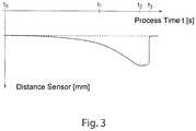
- FIG. 3shows the variation over time of the changing determined value of a distance between a fixed laser processing head and a bulge formed a piercing operation.
- a laser processing machine 1configured as a laser cutting machine is shown in a perspective view.
- Further laser processing machinescan include a laser welding machine or a combined punching/laser cutting machine.
- the laser processing machine 1comprises, for example, a CO 2 laser, a diode laser, or a solid-state laser as a laser beam generator 2 , a laser processing head 3 that can move in the X, Y and Z directions and a workpiece support 4 .
- a laser beam 5is generated in the laser beam generator 2 .
- the laser beam 5is guided from the laser beam generator 2 to the laser processing head 3 by a fiber-optic cable (not shown) or deflecting mirrors (not shown).
- the laser beam 5is directed by a focusing optical system arranged in the laser processing head 3 onto a workpiece 6 , which is arranged on the workpiece support 4 .
- the laser processing machine 1is additionally provided with process gases 7 , for example oxygen and nitrogen. Compressed air or application-specific gases may alternatively or additionally also be provided. The use of the individual gases is dependent on the material of the workpiece 6 to be machined and on quality requirements for the cut edges.
- the process gas 7is fed to a laser processing nozzle 8 of the laser processing head 3 , from which the gas 7 exits together along with the laser beam 5 .
- the laser processing head 3includes a distance sensor system 9 for obtaining a measurement of a distance, A, between the laser processing nozzle 8 and the workpiece 6 .
- the distance sensor system 9can be integrated in the laser processing head.
- the distance sensor system 9includes a capacitive sensor system in certain embodiments.
- the distance sensor system 9can include an inductive or optical sensor system in certain embodiments.
- the laser processing machine 1also comprises a machine controller 10 for moving the laser processing head 3 together with the laser processing nozzle 8 in the X, Y and Z directions.
- the machine controller 10is communicably coupled to one or more actuators configured to move the laser processing head 3 with respect to the workpiece support 4 .
- the workpiece 6may be a sheet of steel with a sheet thickness of at least 10 mm.
- FIG. 2Ashows the beginning (time to) of the piercing operation, in which the laser beam 5 is transmitted to pierce the workpiece 6 at a piercing point 11 by means of a pulsed or continuous transmission of the laser beam 5 and with oxygen as the process gas 7 .
- the initial nozzle distance A 0 of the laser processing nozzle 8 from the workpiece surface 12corresponds to a setpoint distance B predetermined as a fixed distance of for example 5 mm.
- a piercing hole 13the depth of which is approximately 1 ⁇ 3 of the workpiece thickness, has been pierced into the workpiece surface 12 at the time t 1 by the laser beam 5 and the process gas 7 .
- the material of the workpiece that is melted during the piercingis formed around the piercing hole 13 and forms a bulge 14 on the upper side 12 of the workpiece 6 .
- the distance between the laser processing nozzle 8e.g.
- a distal end of the laser processing nozzle) and the bulge 14is measured continuously with the distance sensor system 9 , and a control device 15 maintains the distance between the laser processing nozzle 8 and the bulge 14 at the setpoint distance B.
- the height of the workpiececan be adjusted by adjusting a height of the workpiece support 4 via the control device 15 , which can be integrated in the machine controller 10 .
- the distance between the laser processing nozzle 8 and the workpiece 6i.e. the plan upper side 12 or the formed bulge 14 , can be adjusted by moving the workpiece support 4 in a direction orthogonal to a plane of the workpiece surface 12 .
- the nozzle distance A 1 of the laser processing nozzle 8 from the actual workpiece surface 12is changed by the vertically growing bulge 14 and is greater by the height H of the bulge 14 than the initial nozzle distance A 0 (A 1 >A 0 ).
- the focus positionmay be displaced downward, to keep a focus position constant in relation to the workpiece 6 .
- the depth of the piercing hole 13 at the time t 2is approximately 2 ⁇ 3 of the workpiece thickness.
- the height H of the bulge 14has correspondingly increased further and the distance of the laser processing nozzle 8 from the bulge 14 has been controlled to the setpoint distance B.
- the further vertically grown bulge 14also has the effect that the nozzle distance A 2 of the laser processing nozzle 8 from the actual workpiece surface 12 has increased and is greater by the height H of the bulge 14 than the initial nozzle distance A 0 (A 2 >A 1 >A 0 ).
- FIG. 2Dshows the time t 3 , at which the piercing hole 13 has been pierced and the piercing operation has been completed. If, as represented in FIG. 2D , the bulge 14 has already come away from the upper side 12 of the workpiece, the laser processing nozzle 8 is reset to the initial distance A 0 from the workpiece surface 12 .
- a piercing parametersuch as the distance of the laser processing nozzle 8 from the bulge 14
- other piercing parameterssuch as the focus position, or other piercing parameters may also be changed in dependence on the nozzle distance A or on the height H of the bulge 14 .
- a piercing parametersuch as the distance of the laser processing nozzle 8 from the bulge 14
- other piercing parameterssuch as the focus position, or other piercing parameters
- the nozzle distance A and/or the height H of the bulge 14is/are determined from the distance the laser processing nozzle 8 moves perpendicular to the workpiece surface 12 .
- FIG. 3shows the (filtered) variation over time of the changing measured value determined via the distance sensor system 9 during the piercing operation with a fixed laser processing head 3 .
- the measured valuechanges on account of the accreting bulge 14 , i.e. on account of the reduction in the distance between the upper side of the bulge and the lower side of laser processing nozzle 8 .
- the measured variation of the sensor signalmay be converted into a variation of the actual distance between the laser processing nozzle 8 and the bulge 14 , for example with the aid of conversion characteristics that are empirically determined in advance in test measurements and stored in the control device 15 .
- the data thus determinedserves as a basis for controlling the distance between the laser processing nozzle 8 and the bulge 14 .
Landscapes
- Physics & Mathematics (AREA)
- Optics & Photonics (AREA)
- Engineering & Computer Science (AREA)
- Plasma & Fusion (AREA)
- Mechanical Engineering (AREA)
- Robotics (AREA)
- Laser Beam Processing (AREA)
Abstract
Description
- the focus position can be displaced downward, to keep the focus position in relation to the workpiece surface constant or change it as desired;
- the focus diameter can be changed, to keep the focus diameter on the workpiece constant or change it as desired;
- the gas pressure can be increased, to keep the gas pressure on the workpiece constant or change it as desired;
- the power of the laser beam can be increased, to keep the power on the workpiece constant or change it as desired; and/or
- the process gas can be changed, for example from initially oxygen to an inert gas.
- the focus diameter can be adjusted, to keep the focus diameter on the
workpiece 6 constant; - the gas pressure of the
process gas 7 can be adjusted, to keep the gas pressure on theworkpiece 6 constant (inFIGS. 2A to 2C , a rise in the gas pressure is schematically indicated by flow arrows of differing thickness); - the power of the
laser beam 5 can be adjusted, to keep the power on theworkpiece 6 constant; and/or - the type of gas of the
process gas 7 can be changed, for example from initially oxygen to an inert gas.
- the focus diameter can be adjusted, to keep the focus diameter on the
Claims (7)
Applications Claiming Priority (3)
| Application Number | Priority Date | Filing Date | Title |
|---|---|---|---|
| DE102014217154.7 | 2014-08-28 | ||
| DE102014217154.7ADE102014217154B4 (en) | 2014-08-28 | 2014-08-28 | Method for piercing into metallic workpieces by means of a laser beam and associated laser processing machine and computer program product |
| PCT/EP2015/068600WO2016030199A1 (en) | 2014-08-28 | 2015-08-12 | Method for puncturing metal workpieces by means of a laser beam and associated laser machining machine and computer program product |
Related Parent Applications (1)
| Application Number | Title | Priority Date | Filing Date |
|---|---|---|---|
| PCT/EP2015/068600ContinuationWO2016030199A1 (en) | 2014-08-28 | 2015-08-12 | Method for puncturing metal workpieces by means of a laser beam and associated laser machining machine and computer program product |
Publications (2)
| Publication Number | Publication Date |
|---|---|
| US20170157711A1 US20170157711A1 (en) | 2017-06-08 |
| US11045908B2true US11045908B2 (en) | 2021-06-29 |
Family
ID=53872049
Family Applications (1)
| Application Number | Title | Priority Date | Filing Date |
|---|---|---|---|
| US15/441,560Active2037-12-03US11045908B2 (en) | 2014-08-28 | 2017-02-24 | Piercing workpieces by a laser beam and an associated laser processing machine |
Country Status (6)
| Country | Link |
|---|---|
| US (1) | US11045908B2 (en) |
| EP (1) | EP3186031B1 (en) |
| CN (1) | CN106660168B (en) |
| DE (1) | DE102014217154B4 (en) |
| PL (1) | PL3186031T3 (en) |
| WO (1) | WO2016030199A1 (en) |
Families Citing this family (6)
| Publication number | Priority date | Publication date | Assignee | Title |
|---|---|---|---|---|
| KR20170087610A (en)* | 2016-01-21 | 2017-07-31 | 삼성전자주식회사 | Apparatus for cutting a wafer |
| DE102017111211B4 (en)* | 2017-05-23 | 2023-10-12 | Automotive Lighting Reutlingen Gmbh | Method for material-removing laser processing of a workpiece |
| DE102019132619A1 (en)* | 2019-12-02 | 2021-06-02 | Trumpf Laser Gmbh | Method for distance measurement using OCT and associated computer program product |
| ES2921849B2 (en)* | 2021-02-19 | 2023-09-25 | Fund Tekniker | Method for single pulse micro-drilling process with a laser head, laser head and micro-drilling machine |
| CN116689954A (en)* | 2022-02-24 | 2023-09-05 | 大族激光科技产业集团股份有限公司 | Plate laser cutting method, control device, laser cutting machine and storage medium |
| CN116493753B (en)* | 2023-06-29 | 2023-09-12 | 合肥经济学院 | High-precision laser welding robot |
Citations (15)
| Publication number | Priority date | Publication date | Assignee | Title |
|---|---|---|---|---|
| JPH01218780A (en)* | 1988-02-27 | 1989-08-31 | Nippei Toyama Corp | Method for controlling start of work in laser beam machine |
| JPH03490Y2 (en) | 1984-10-29 | 1991-01-10 | ||
| JPH0452094A (en) | 1990-06-18 | 1992-02-20 | Mitsubishi Electric Corp | Laser beam machine |
| JPH05123885A (en)* | 1991-10-30 | 1993-05-21 | Nippei Toyama Corp | Laser beam machining method |
| JPH0952187A (en) | 1995-08-09 | 1997-02-25 | Mitsubishi Electric Corp | Laser processing machine system |
| JP3131357B2 (en) | 1995-04-19 | 2001-01-31 | 三菱電機株式会社 | Laser processing method |
| JP2001321975A (en) | 2000-05-11 | 2001-11-20 | Koike Sanso Kogyo Co Ltd | Laser cutting method |
| US20030192865A1 (en)* | 2002-04-16 | 2003-10-16 | W.A. Whitney Co. | Method and apparatus for laser piercing and cutting metal sheet and plate |
| US6831270B2 (en) | 2002-11-11 | 2004-12-14 | Shimadzu Corporation | Method for preparing a sample for use in laser desorption ionization mass spectrometry and sample plate used in such a method |
| US20050178749A1 (en)* | 2004-02-05 | 2005-08-18 | Yamazaki Mazak Kabushiki Kaisha, A Japanese Corporation. | Plasma detector and laser beam machine with plasma detector |
| JP2009190064A (en) | 2008-02-14 | 2009-08-27 | Mitsubishi Electric Corp | Laser processing method and laser processing machine |
| WO2013007674A1 (en) | 2011-07-13 | 2013-01-17 | Trumpf Werkzeugmaschinen Gmbh + Co. Kg | Method for machining a workpiece, and machining device |
| CN102892547A (en) | 2010-05-10 | 2013-01-23 | 普雷茨特激光技术有限公司 | Material-working device with in-situ measurement of the working distance |
| DE102013210857B3 (en) | 2013-06-11 | 2014-08-21 | Trumpf Werkzeugmaschinen Gmbh + Co. Kg | Method for piercing into metallic workpieces by means of a laser beam |
| DE102013210845A1 (en) | 2013-06-11 | 2014-12-11 | Trumpf Werkzeugmaschinen Gmbh + Co. Kg | Method for piercing into metallic workpieces by means of a laser beam |
Family Cites Families (1)
| Publication number | Priority date | Publication date | Assignee | Title |
|---|---|---|---|---|
| JP2577256B2 (en) | 1989-05-30 | 1997-01-29 | 新明和工業株式会社 | Control method of cutting machine |
- 2014
- 2014-08-28DEDE102014217154.7Apatent/DE102014217154B4/ennot_activeExpired - Fee Related
- 2015
- 2015-08-12EPEP15750721.1Apatent/EP3186031B1/enactiveActive
- 2015-08-12WOPCT/EP2015/068600patent/WO2016030199A1/enactiveApplication Filing
- 2015-08-12CNCN201580046710.0Apatent/CN106660168B/enactiveActive
- 2015-08-12PLPL15750721Tpatent/PL3186031T3/enunknown
- 2017
- 2017-02-24USUS15/441,560patent/US11045908B2/enactiveActive
Patent Citations (20)
| Publication number | Priority date | Publication date | Assignee | Title |
|---|---|---|---|---|
| JPH03490Y2 (en) | 1984-10-29 | 1991-01-10 | ||
| JPH01218780A (en)* | 1988-02-27 | 1989-08-31 | Nippei Toyama Corp | Method for controlling start of work in laser beam machine |
| JPH0452094A (en) | 1990-06-18 | 1992-02-20 | Mitsubishi Electric Corp | Laser beam machine |
| JPH05123885A (en)* | 1991-10-30 | 1993-05-21 | Nippei Toyama Corp | Laser beam machining method |
| JP3115060B2 (en) | 1991-10-30 | 2000-12-04 | 株式会社日平トヤマ | Laser processing method |
| JP3131357B2 (en) | 1995-04-19 | 2001-01-31 | 三菱電機株式会社 | Laser processing method |
| JPH0952187A (en) | 1995-08-09 | 1997-02-25 | Mitsubishi Electric Corp | Laser processing machine system |
| JP2001321975A (en) | 2000-05-11 | 2001-11-20 | Koike Sanso Kogyo Co Ltd | Laser cutting method |
| US20030192865A1 (en)* | 2002-04-16 | 2003-10-16 | W.A. Whitney Co. | Method and apparatus for laser piercing and cutting metal sheet and plate |
| US6831270B2 (en) | 2002-11-11 | 2004-12-14 | Shimadzu Corporation | Method for preparing a sample for use in laser desorption ionization mass spectrometry and sample plate used in such a method |
| US20050178749A1 (en)* | 2004-02-05 | 2005-08-18 | Yamazaki Mazak Kabushiki Kaisha, A Japanese Corporation. | Plasma detector and laser beam machine with plasma detector |
| JP2009190064A (en) | 2008-02-14 | 2009-08-27 | Mitsubishi Electric Corp | Laser processing method and laser processing machine |
| CN102892547A (en) | 2010-05-10 | 2013-01-23 | 普雷茨特激光技术有限公司 | Material-working device with in-situ measurement of the working distance |
| US8982339B2 (en) | 2010-05-10 | 2015-03-17 | Precitec Optronik Gmbh | Material-working device with in-situ measurement of the working distance |
| WO2013007674A1 (en) | 2011-07-13 | 2013-01-17 | Trumpf Werkzeugmaschinen Gmbh + Co. Kg | Method for machining a workpiece, and machining device |
| DE102011079083A1 (en) | 2011-07-13 | 2013-01-17 | Trumpf Werkzeugmaschinen Gmbh + Co. Kg | Method for processing a workpiece and a machining device |
| US9579749B2 (en) | 2011-07-13 | 2017-02-28 | Trumpf Werkzeugmaschinen Gmbh + Co. Kg | Method for processing a workpiece and processing device |
| DE102013210857B3 (en) | 2013-06-11 | 2014-08-21 | Trumpf Werkzeugmaschinen Gmbh + Co. Kg | Method for piercing into metallic workpieces by means of a laser beam |
| DE102013210845A1 (en) | 2013-06-11 | 2014-12-11 | Trumpf Werkzeugmaschinen Gmbh + Co. Kg | Method for piercing into metallic workpieces by means of a laser beam |
| US20160096239A1 (en) | 2013-06-11 | 2016-04-07 | Trumpf Werkzeugmaschinen Gmbh + Co. Kg | Piercing Metal Workpieces by a Laser Beam |
Non-Patent Citations (3)
| Title |
|---|
| International Search Report for corresponding PCT Application No. PCT/EP2015/068600, dated Nov. 24, 2015, 4 pages. |
| Machine translation of JP 01-218780 performed on Oct. 18, 2019.* |
| Machine translation of JP 05-123885 performed on Oct. 21, 2019.* |
Also Published As
| Publication number | Publication date |
|---|---|
| US20170157711A1 (en) | 2017-06-08 |
| EP3186031B1 (en) | 2019-07-31 |
| DE102014217154A1 (en) | 2016-03-03 |
| CN106660168A (en) | 2017-05-10 |
| CN106660168B (en) | 2019-02-15 |
| EP3186031A1 (en) | 2017-07-05 |
| WO2016030199A1 (en) | 2016-03-03 |
| PL3186031T3 (en) | 2020-03-31 |
| DE102014217154B4 (en) | 2016-09-22 |
Similar Documents
| Publication | Publication Date | Title |
|---|---|---|
| US11045908B2 (en) | Piercing workpieces by a laser beam and an associated laser processing machine | |
| US9956648B2 (en) | Piercing metal workpieces by a laser beam | |
| JP5868559B1 (en) | Laser processing method and laser processing apparatus | |
| US20210354232A1 (en) | Methods for the automated determination of the influence of a laser processing parameter on a laser processing operation, laser processing machine, and computer program product | |
| US20210379699A1 (en) | Processes and devices for beam processing of plate-shaped or tubular workpieces | |
| US9536551B2 (en) | Laser processing method and apparatus | |
| US20140353294A1 (en) | Plasma cutting method and plasma cutting device | |
| WO2017134964A1 (en) | Laser processing machine and laser processing method | |
| US20240207976A1 (en) | Method for cutting at least one workpiece from a metal sheet | |
| US20240326172A1 (en) | Laser cutting process for dividing a metal sheet into at least one workpiece and a plurality of residual portions, and laser processing installation | |
| US20100102045A1 (en) | Method of cutting parts to be machined using a pulsed laser | |
| JP5201114B2 (en) | Laser processing apparatus and laser processing method | |
| US20210354244A1 (en) | Laser machining apparatus and laser machining method | |
| US12122060B2 (en) | Method and machining tool for cutting workpieces and associated computer program product | |
| EP3205439B1 (en) | Piercing method and laser processing apparatus | |
| KR101149099B1 (en) | Apparatus for cutting coil using lazer beam and method thereof | |
| JP4978111B2 (en) | Laser welding method and apparatus | |
| TWI595955B (en) | A laser machining method | |
| JP2005034865A (en) | Roll processing apparatus and processing method | |
| CN111902236B (en) | Laser cutting method, laser cutting machine and computer program product | |
| EP4169658A1 (en) | Laser machining tool and workpiece machining method | |
| KR102226468B1 (en) | Apparatus for keeping head gap of laser welder | |
| US11813698B2 (en) | Laser cutting method and machine, and automatic programing apparatus | |
| EP3819069B1 (en) | Laser machining method | |
| JP2009190064A (en) | Laser processing method and laser processing machine |
Legal Events
| Date | Code | Title | Description |
|---|---|---|---|
| AS | Assignment | Owner name:TRUMPF WERKZEUGMASCHINEN GMBH + CO. KG, GERMANY Free format text:ASSIGNMENT OF ASSIGNORS INTEREST;ASSIGNORS:SPIESS, MARTIN;HALLASCH, DIETER;KNORRECK, DANIEL;AND OTHERS;SIGNING DATES FROM 20170308 TO 20170323;REEL/FRAME:042175/0408 | |
| STPP | Information on status: patent application and granting procedure in general | Free format text:DOCKETED NEW CASE - READY FOR EXAMINATION | |
| STPP | Information on status: patent application and granting procedure in general | Free format text:NON FINAL ACTION MAILED | |
| STPP | Information on status: patent application and granting procedure in general | Free format text:RESPONSE TO NON-FINAL OFFICE ACTION ENTERED AND FORWARDED TO EXAMINER | |
| STPP | Information on status: patent application and granting procedure in general | Free format text:NON FINAL ACTION MAILED | |
| STPP | Information on status: patent application and granting procedure in general | Free format text:FINAL REJECTION MAILED | |
| STPP | Information on status: patent application and granting procedure in general | Free format text:RESPONSE AFTER FINAL ACTION FORWARDED TO EXAMINER | |
| STCV | Information on status: appeal procedure | Free format text:APPEAL BRIEF (OR SUPPLEMENTAL BRIEF) ENTERED AND FORWARDED TO EXAMINER | |
| STPP | Information on status: patent application and granting procedure in general | Free format text:NOTICE OF ALLOWANCE MAILED -- APPLICATION RECEIVED IN OFFICE OF PUBLICATIONS | |
| STPP | Information on status: patent application and granting procedure in general | Free format text:AWAITING TC RESP., ISSUE FEE NOT PAID | |
| STPP | Information on status: patent application and granting procedure in general | Free format text:NOTICE OF ALLOWANCE MAILED -- APPLICATION RECEIVED IN OFFICE OF PUBLICATIONS | |
| STPP | Information on status: patent application and granting procedure in general | Free format text:PUBLICATIONS -- ISSUE FEE PAYMENT RECEIVED | |
| STPP | Information on status: patent application and granting procedure in general | Free format text:PUBLICATIONS -- ISSUE FEE PAYMENT VERIFIED | |
| STCF | Information on status: patent grant | Free format text:PATENTED CASE | |
| MAFP | Maintenance fee payment | Free format text:PAYMENT OF MAINTENANCE FEE, 4TH YEAR, LARGE ENTITY (ORIGINAL EVENT CODE: M1551); ENTITY STATUS OF PATENT OWNER: LARGE ENTITY Year of fee payment:4 |