US11045675B2 - Belleville seal for valve seat having a tear drop laminar flow feature - Google Patents
Belleville seal for valve seat having a tear drop laminar flow featureDownload PDFInfo
- Publication number
- US11045675B2 US11045675B2US16/267,288US201916267288AUS11045675B2US 11045675 B2US11045675 B2US 11045675B2US 201916267288 AUS201916267288 AUS 201916267288AUS 11045675 B2US11045675 B2US 11045675B2
- Authority
- US
- United States
- Prior art keywords
- fluid
- support body
- fire
- flow
- protection system
- Prior art date
- Legal status (The legal status is an assumption and is not a legal conclusion. Google has not performed a legal analysis and makes no representation as to the accuracy of the status listed.)
- Active
Links
- 239000012530fluidSubstances0.000claimsabstractdescription79
- 230000004913activationEffects0.000claimsabstractdescription40
- 238000011144upstream manufacturingMethods0.000claimsabstractdescription15
- 230000000903blocking effectEffects0.000claimsdescription18
- 238000007789sealingMethods0.000abstractdescription18
- XLYOFNOQVPJJNP-UHFFFAOYSA-NwaterSubstancesOXLYOFNOQVPJJNP-UHFFFAOYSA-N0.000description26
- 238000004891communicationMethods0.000description7
- 239000011521glassSubstances0.000description6
- 230000007246mechanismEffects0.000description6
- 230000000712assemblyEffects0.000description5
- 238000000429assemblyMethods0.000description5
- 239000003638chemical reducing agentSubstances0.000description4
- 230000000717retained effectEffects0.000description4
- 230000001960triggered effectEffects0.000description4
- 238000010586diagramMethods0.000description3
- 230000008014freezingEffects0.000description3
- 238000007710freezingMethods0.000description3
- IJGRMHOSHXDMSA-UHFFFAOYSA-NAtomic nitrogenChemical compoundN#NIJGRMHOSHXDMSA-UHFFFAOYSA-N0.000description2
- 238000010276constructionMethods0.000description2
- 239000007788liquidSubstances0.000description2
- 230000004044responseEffects0.000description2
- 229910001369BrassInorganic materials0.000description1
- LFQSCWFLJHTTHZ-UHFFFAOYSA-NEthanolChemical compoundCCOLFQSCWFLJHTTHZ-UHFFFAOYSA-N0.000description1
- 229910000990Ni alloyInorganic materials0.000description1
- 235000014676Phragmites communisNutrition0.000description1
- 239000004809TeflonSubstances0.000description1
- 229920006362Teflon®Polymers0.000description1
- 125000003158alcohol groupChemical group0.000description1
- 150000001298alcoholsChemical class0.000description1
- 230000002528anti-freezeEffects0.000description1
- 230000008901benefitEffects0.000description1
- 230000015572biosynthetic processEffects0.000description1
- 239000010951brassSubstances0.000description1
- 239000011248coating agentSubstances0.000description1
- 238000000576coating methodMethods0.000description1
- 230000006835compressionEffects0.000description1
- 238000007906compressionMethods0.000description1
- 238000009833condensationMethods0.000description1
- 230000005494condensationEffects0.000description1
- 238000007599dischargingMethods0.000description1
- 239000007789gasSubstances0.000description1
- 230000008676importEffects0.000description1
- 238000010348incorporationMethods0.000description1
- 238000009434installationMethods0.000description1
- 239000002184metalSubstances0.000description1
- 229910052751metalInorganic materials0.000description1
- 238000012986modificationMethods0.000description1
- 230000004048modificationEffects0.000description1
- 229910052757nitrogenInorganic materials0.000description1
- 230000001629suppressionEffects0.000description1
- 239000002023woodSubstances0.000description1
Images


Classifications
- A—HUMAN NECESSITIES
- A62—LIFE-SAVING; FIRE-FIGHTING
- A62C—FIRE-FIGHTING
- A62C35/00—Permanently-installed equipment
- A62C35/58—Pipe-line systems
- A62C35/68—Details, e.g. of pipes or valve systems
- A—HUMAN NECESSITIES
- A62—LIFE-SAVING; FIRE-FIGHTING
- A62C—FIRE-FIGHTING
- A62C37/00—Control of fire-fighting equipment
- A62C37/08—Control of fire-fighting equipment comprising an outlet device containing a sensor, or itself being the sensor, i.e. self-contained sprinklers
- A62C37/10—Releasing means, e.g. electrically released
- A62C37/11—Releasing means, e.g. electrically released heat-sensitive
- A—HUMAN NECESSITIES
- A62—LIFE-SAVING; FIRE-FIGHTING
- A62C—FIRE-FIGHTING
- A62C35/00—Permanently-installed equipment
- A62C35/58—Pipe-line systems
- A62C35/62—Pipe-line systems dry, i.e. empty of extinguishing material when not in use
- A—HUMAN NECESSITIES
- A62—LIFE-SAVING; FIRE-FIGHTING
- A62C—FIRE-FIGHTING
- A62C37/00—Control of fire-fighting equipment
- A62C37/36—Control of fire-fighting equipment an actuating signal being generated by a sensor separate from an outlet device
- A62C37/38—Control of fire-fighting equipment an actuating signal being generated by a sensor separate from an outlet device by both sensor and actuator, e.g. valve, being in the danger zone
- A62C37/42—Control of fire-fighting equipment an actuating signal being generated by a sensor separate from an outlet device by both sensor and actuator, e.g. valve, being in the danger zone with mechanical connection between sensor and actuator, e.g. rods, levers
Definitions
- the present inventionrelates generally to fire protection and more particularly to valves and seal assemblies for use in fire-protection systems.
- Fire sprinkler system installation and operationare subject to nationally recognized codes.
- dry sprinklersare used in areas that are or may be exposed to freezing conditions, such as in freezers, unheated internal areas, walkways, etc.
- supply conduitsrun in a space where the water in the supply conduit is not subject to freezing.
- a dry sprinklerwhich is “dry” because it does not contain water until the sprinkler system has been triggered, is attached to the supply conduit and extends into a space where the water would otherwise be subject to freezing.
- the typical construction of a dry sprinklercomprises a tube (“drop”) with a pipe connector at the inlet end of the tube (for connecting the inlet end to the supply pipe network of the fire suppression system), a seal member at the inlet end to prevent water from entering the tube prior to activation such as in the case of a fire, and a mechanism to maintain the seal at the inlet end until the sprinkler is activated.
- a nozzle with an outlet and a deflectoris attached to the opposite, outlet end of the tube.
- the tubeis sometimes vented to the atmosphere to allow drainage of any condensation that may form in the tube.
- Such dry sprinklersare disclosed, for example, in U.S. Pat.
- the actuating mechanismcan include a rod or other similar rigid structure that extends through the tube between the nozzle end and the inlet end to maintain a seal at the inlet end.
- the actuating mechanismfurther may include a thermally responsive element that supports the rod or the like at the nozzle end and thereby supports the seal at the inlet end.
- the tubeis also sealed at the nozzle end of the tube, and the rod is supported at the nozzle end by the seal member which is itself supported by the thermally responsive support element.
- the space in the tube between the two seal memberscan be pressurized with a gas, such as dry air or nitrogen, or filled with a liquid such as an antifreeze solution.
- the thermally responsive support elementfails, thereby allowing the rod to move releasing the inlet end seal (and also any outlet seal at the nozzle end of the tube) to allow water from the supply conduit to flow into and through the tube to the nozzle.
- Such fire-protection systemsgenerally include one or more valves for controlling the flow of water or other fire-suppression liquid (collectively referenced as “water” herein).
- waterwater
- present applicationdiscloses valves for use in such fire-protection systems or with a dry sprinkler as described above, or to be incorporated into a dry sprinkler.
- present applicationalso discloses a fire-protection system comprising such a valve or dry sprinkler.
- one aspect of the present disclosureis directed to a fire-protection system for delivering a fire-control fluid.
- the fire-protection systemcomprises a valve having a body with an inlet, an outlet, and a fluid passageway connecting the inlet with the outlet.
- a seal memberis supportable across the passageway to close the passageway.
- the seal memberis supported across the passageway in a sealing position in a pre-activation condition of the valve.
- the seal memberis movable from the sealing position to a fluid-flow position in an activated condition of the valve.
- the seal membercomprises a support body having a longitudinal axis, a seat, a leading surface facing in an upstream direction from the seat, and a trailing surface located in a downstream direction from the seat and contoured radially inwardly in the downstream direction.
- a Belleville washeris mounted on the seat of the support body.
- the fire-protection systemcomprises a valve having a body with a fluid aperture having an aperture axis, and a fluid-flow axis parallel to a direction of flow of fluid through the fluid aperture.
- a seal memberis supportable to close the fluid aperture.
- the seal memberhas a blocking position and orientation, and the seal member prevents a fluid flow through the aperture in a pre-activation condition of the fire-protection system when in the blocking position and orientation.
- the seal memberis movable from the blocking position and orientation to a fluid-flow position and orientation in an activated condition of the fire-protection system.
- the seal membercomprises a Belleville washer having a washer axis.
- the support bodycomprises a leading portion oriented in an upstream direction with respect to the fluid flow when the seal member is in the fluid-flow position and orientation, and a trailing portion oriented in a downstream direction with respect to the fluid flow when the seal member is in the fluid-flow position and orientation.
- a transverse surfacesupports the Belleville washer, with the washer axis aligned with the aperture axis in the blocking position and orientation, and with the washer axis at an angle to the fluid-flow axis when the seal member is in the fluid-flow position and orientation.
- the support bodyis streamlined with respect to the direction of fluid flow when the seal member is in the fluid-flow position and orientation.
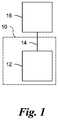
- FIG. 1is a schematic diagram of fire-protection system including a thermal trigger assembly configured for remote mechanical actuation of another fire-protection system component in accordance with a preferred embodiment of the invention
- FIG. 2is a side perspective view of a fire-protection system including a valve, an activation component, and a sprinkler head, in accordance with a preferred embodiment of the invention
- FIG. 3is a cross-sectional view of the fire-protection system of FIG. 2 ;
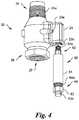
- FIG. 4is an enlarged and partially exploded side perspective view of fire-protection system of FIG. 2 , including the valve component and a portion of the activation component;
- FIG. 5is an enlarged partial bottom perspective view of the fire-protection system of FIG. 2 , including the sprinkler head and a portion of the activation component;
- FIG. 6is an enlarged partial elevational cross-sectional view of the components of FIG. 5 ;
- FIG. 7is an enlarged partial side perspective cross-sectional view of the valve component and the activation component of FIG. 2 , shown in the pre-activation condition and sealing position;
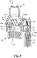
- FIG. 8is an enlarged partial side perspective cross-sectional view of the valve component and the proximal base of FIG. 7 , shown in the activated condition;
- FIG. 9is an enlarged partial elevational cross-sectional view of an alternative embodiment of activation component of the device of FIG. 2 , shown in the activated condition;
- FIG. 10is a partial side perspective view of a bracket and a portion of the activation component of FIG. 2 secured to a conduit in accordance with a preferred embodiment of the invention
- FIG. 11an enlarged partial elevational cross-sectional view of a valve component in accordance with a preferred embodiment of the invention, shown in the pre-activation condition and sealing position;
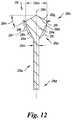
- FIG. 12is an enlarged elevational cross-sectional view of a seal member of the valve component of FIG. 4 ;
- FIG. 13is an enlarged elevational cross-sectional view of a dry sprinkler according to another preferred embodiment of the invention, mounted through a portion of a structure, shown in a pre-activation condition;
- FIG. 14is an enlarged elevational cross-sectional view of the embodiment of FIG. 13 , shown in an activated condition;
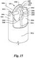
- FIG. 15is an enlarged partial side perspective view of the embodiment of FIG. 13 , shown in an orientation consistent with the activated condition.
- Upstreamrefers to a direction from which fluid flows
- downstreamrefers to a direction to which fluid flows, in an activated condition.
- the terms “a,” “an,” and “the”are not limited to one element, but instead should be read as meaning “at least one.”
- the terminologyincludes the words noted above, derivatives thereof, and words of similar import.
- valves and fire-protection devicesmay be used advantageously as part of systems including activation components and/or thermal trigger assemblies previously disclosed, including devices disclosed by the Applicant.
- activation components and/or thermal trigger assembliespreviously disclosed, including devices disclosed by the Applicant.
- the preferred inventionis also related to U.S. patent application Ser. No. 15/790,321 filed Oct. 23, 2017 (Pub. No. US 2018-0043198 A1); Ser. No. 15/648,861 filed Jul. 13, 2017 (Pub. No. US 2017-0340911 A1); Ser. No. 15/623,048 filed Jun. 14, 2017 (Pub. No. US 2018-0361182 A1); and Ser. No. 15/222,770 filed Jul. 28, 2016 (U.S. Pat. No. 9,901,763); the contents of each application identified in this paragraph are incorporated into the present application by reference in their entirety.
- a thermal trigger assembly 10is configured for remote mechanical actuation of another fire-protection system component 16 , which in the preferred invention preferably is a valve as described below.
- the thermal trigger assembly 10comprises an activation component 12 and a flexible connector 14 configured to allow the activation component 12 to remotely mechanically actuate the other fire-protection system component 16 , which in some preferred embodiments (discussed below) is a valve, either of a new type presently disclosed herein, or as previously disclosed, for discharging water into one or more sprinklers.
- the other fire-protection system component 16also may comprise a switch or a relay having a throw, a magnet (such as a Reed switch or relay), or an equivalent that can be mechanically moved, or another type of fire-protection system device actuatable by a mechanical input.
- a switch or a relay having a throw, a magnetsuch as a Reed switch or relay
- an equivalentthat can be mechanically moved, or another type of fire-protection system device actuatable by a mechanical input.
- the activation component 12 and the flexible connector 14are not necessarily distributed in space in the same manner as they are depicted in the block diagram of FIG. 1 .
- a fire-protection system in the form of a dry sprinkler deviceincludes a thermal trigger assembly configured for remote mechanical configuration of another fire-protection system component, which in FIGS. 2-4, 7 , and 8 takes the form of a valve 20 according to the preferred invention.
- the valve 20may be controlled by any suitable trigger assembly, including the trigger assemblies disclosed in U.S. patent application Ser. No. 15/623,048, published as Pub. No. US 2018-0361182 A1 (as discussed herein), or the trigger assemblies discussed in any of the other U.S. patents or patent applications incorporated by reference in the present application.
- the thermal trigger assemblycomprises an activation component 50 including a proximal base 60 having a body 61 , proximal end 62 , and a distal end 64 with respect to the valve 20 .
- a nut 63 at the distal end 64 of the body 61has a notched fitting 63 a for attaching a flexible connector 120 (described below), and the nut engages the threads 64 a on the body 61 .
- a proximal movable member 70is movable with respect to the proximal base 60 .
- a bias member, best seen in FIGS. 7 and 8is shown as a coil spring 80 .
- a “bias member” as discussed hereincould alternatively take the form of other devices capable of supplying a restorative force in response to a displacement—for example, an air spring or a leaf spring.
- the bias member(the coil spring 80 ) is located with respect to the proximal base 60 to bias the proximal movable member 70 from a pre-activation position, shown in FIG. 7 , to an activated position, shown in FIG. 8 , with respect to the proximal base 60 .
- the activated positionis located proximally of the pre-activation position, so that a movement of the proximal movable member 70 from the pre-activation condition to the activated position with respect to the proximal base 60 is a movement generally proximally—that is, toward the other fire-protection component, the valve 20 (upwardly when viewing FIG. 8 ).
- a movement of the proximal movable member 70 from the pre-activation condition to the activated position with respect to the proximal base 60is a movement generally proximally—that is, toward the other fire-protection component, the valve 20 (upwardly when viewing FIG. 8 ).
- the proximal end 71 of the proximal moveable member 70is in contact with the latch 32 .
- the proximal end 70 a of the proximal moveable member 70makes a forcible impact with a portion of the other fire protection component—for example, the latch 32 of the valve 20 .
- the thermal trigger assemblyalso comprises a distal base 90 , a distal movable member in the form of a pull 100 , and a thermally responsive element 110 , which in some embodiments is an alcohol-filled glass bulb, is retained by the distal base 90 until a predetermined thermodynamic condition occurs or is reached.
- a thermally responsive element 110which in some embodiments is an alcohol-filled glass bulb, is retained by the distal base 90 until a predetermined thermodynamic condition occurs or is reached.
- the distal movable membercould take the form of an end portion of the flexible connector 120 .
- the thermally responsive element 110is configured to lose structural integrity under the predetermined thermodynamic condition and thereby allow the distal movable member 100 to move from a pre-activation position to an activated position located generally proximally (that is, toward the valve 20 ) with respect to the distal base 90 .
- the distal base 90comprises a body 92 with a proximal end 94 , a distal end 96 , and an extension 98 (lying within the dashed box in FIG. 6 ) extending distally from the distal end 96 , with the extension 98 including one or more arms 99 supporting the thermally responsive element 110 .
- the distal base 90also includes a fulcrum 97 supported by the distal base 90 , which is also supported in the preferred embodiment by the extension 98 .
- the thermal trigger assemblyalso comprises the flexible connector 120 having a proximal end 122 and a distal end 124 , the proximal end 122 being connected to the proximal movable member 70 , and the distal end 124 being connected to the distal movable member 100 .
- the connections between the flexible connector 120 and other componentsmay be direct or maybe indirect, with intervening connecting components disposed between the flexible connector 120 and, for example, the proximal movable member 70 .
- the thermally responsive element 110 retaining the distal movable member, the pull 100 , in the pre-activation position with respect to the distal base 90also retains the proximal movable member 70 in the pre-activation position with respect to the proximal base 60 .
- a biasing force from the bias membercauses a movement of the proximal movable member 70 from the pre-activation position of the proximal movable member 70 ( FIG. 7 ) to the activated position of the proximal movable member 70 ( FIG. 8 ).
- the flexible connector 120includes a flexible hollow outer cable housing 126 with a proximal housing end 128 configured to be stationarily connected with respect to the proximal base 60 and a distal housing end 130 configured to be stationarily connected with respect to the distal base 90 .
- the flexible outer cable housing 126may include at least one joint 126 a joining two or more portions thereof.
- the flexible connector 120also includes a flexible inner member 132 located inside the flexible hollow outer cable housing 126 for movement within the flexible outer cable housing 126 and having a proximal inner member end 134 ( FIG. 7 ) and a distal inner member end 136 ( FIG.
- the proximal inner member end 134being stationarily connected with the proximal movable member 70
- the distal inner member end 136being stationarily connected with the distal movable member, which in the exemplary embodiment is the pull 100 .
- the distal movable membermay, as an alternative to the pull 100 , include other bodies engaged with the flexible connector 120 , the other bodies having any convenient shape.
- the proximal inner member end 134is configured for a mechanical connection with the latch 32 for removing the support provided by the latch 32 from the seal member 28 , thereby permitting a fluid to flow through the fluid passageway 40 of the valve 20 .
- a platform 150is engaged with the fulcrum 97 , the distal movable member 100 , and the thermally responsive element 110 such that the distal movable member 100 and the thermally responsive element 110 restrain the platform 150 on the fulcrum 97 .
- the platform 150is illustrated as a relatively flat plate, generally a platform 150 according to the preferred embodiment can take any shape that is supportable on the fulcrum 97 and that accommodates the necessary engagement of the thermally responsive element 110 and the distal movable member 100 .
- the platform 150pivots about the fulcrum 97 as a result of force from the bias member (the coil spring 80 ) transmitted by the flexible connector 120 , allowing the distal movable member 100 to move to the activated position with respect to the distal base 90 .
- the distal movable member 100takes the form of a pull 100 attached to the distal inner member end 136 of the flexible connector 120 , and the platform 150 has a notch 152 for engaging the pull 100 .
- the valve 20 of the present inventionhas a body 22 with an inlet 25 located at an inlet end 24 , at least one outlet 27 located at an outlet end 26 , and a fluid passageway 40 between the inlet 25 and the outlet 27 .
- the inlet end 24has screw threads 24 a for attachment to a fluid source.
- the body 22includes a removable cover 23 ( FIG. 4 ) attached by screws 23 a (one is shown).
- the removable cover 23has a threaded opening 23 b for attaching the proximal base 60 at the proximal end 62 via threads 62 a .
- the valve 20may have additional outlets (not shown) in fluid communication with the fluid passageway 40 .
- a seal member 28which is shown alone in FIG. 12 and is further described below, is supportable across the passageway 40 to close the passageway 40 by a lever 30 , which is pivotally mounted by means of a lever pivot 30 a located on a cross-member 36 .
- the seal member 28is supported across the passageway in a sealing position in a pre-activation condition of the valve 20 .
- the seal member 28is movable from the sealing position to a fluid-flow position in the activated condition of the valve 20 .
- the lever 30is retained in a sealing position to hold the seal member 28 in place as shown in FIG. 7 to prevent fluid from flowing into and through the valve 20 through the inlet 25 by a latch 32 engaged with the lever 30 .
- the movable member 70is configured to engage the latch 32 for pivotal movement of the latch 32 counter-clockwise (as shown in FIGS. 7 and 8 ) about the pivot 32 a with respect to the lever 30 by a movement of the proximal movable member 70 in the proximal direction in the activation position of FIG. 8 .
- the latch 32is supported by a latch pivot 32 a located on the cross-member 36 .
- a latch bias memberhere a latch spring 32 b acting in compression, retains the latch 32 in position supporting the lever 30 when in the pre-activation condition position of FIG. 7 .
- an adjustment screw 34FIG. 8 ) threadedly engages the lever 30 and a shaft portion 28 a of the seal member 28 to support the seal member 28 , with the combination providing a mechanism to adjust the sealing engagement of the seal member 28 with the inlet 25 .
- the proximal inner member end 134FIG.
- the flexible connector 120is configured for engagement with the latch 32 , either through direct contact or acting through intervening components (such as the proximal movable member 70 ), for removing the support provided by the latch 32 from the seal member 28 so that the seal member 28 moves (under pressure provided by the water) away from the inlet 25 of the valve 20 , thereby permitting a fluid to flow through the fluid passageway 40 (see FIG. 8 ).
- the proximal movable member 70 in the activated positionis sealingly engaged with the proximal base 60 by the seal 170 .
- the seal 170is omitted, and the proximal movable member 70 comprises a weephole 72 permitting fluid communication between a proximal portion 66 of the body 61 of the proximal base 60 with respect to the proximal movable member 70 , and a distal portion 68 of the body 61 of the proximal base 60 with respect to the proximal movable member 70 .
- proximal movable member 70it is advantageous for the proximal movable member 70 to sealingly engage the proximal base 60 where the activation component 50 is used to control the valve 20 for permitting water flow to a sprinkler head 180 , which remains closed until a second thermally responsive element 182 of the sprinkler head 180 (see FIG. 2 ) loses structural integrity under a predetermined thermodynamic condition.
- the sprinkler head 180may include any of the wide variety of sprinkler heads currently common in the art, or any other type of water-discharge device for delivering water or other fluid onto a fire, and may include both open sprinkler heads and sprinkler heads containing plugs or other mechanisms for blocking and permitting fluid flow.
- This combination of componentscreates a system in which water flows through the sprinkler head 180 only if both the thermally responsive element 110 of the distal base 90 and the thermally responsive element, depicted as a fusible member 182 , of the sprinkler head 180 are both activated. If the thermally responsive element 110 alone loses structural integrity, the valve 20 is opened, but water cannot flow through the sprinkler head 180 ; moreover, the sealing engagement of the proximal movable member 70 with the proximal base 60 prevents or minimizes water flow through the proximal base 60 .
- the weephole passage 72 of the proximal movable member 70permits a small amount of water to flow through the proximal base 60 so that the triggering of the valve 20 alone, without the triggering of the sprinkler head 180 , is more easily detected because water leaks through the weephole passage 72 , eventually leaking from the activation component 50 , with water becoming detectable in the vicinity of the distal base 90 .
- a bracket 270according to an exemplary embodiment of the invention supports the distal base 90 on a conduit 280 .
- the other fire component 20 referenced in the discussion of FIG. 1may take the form of a valve 220 , which is similar in many respects to the valve 20 of the above-described preferred embodiment.
- the valve 220has a body 222 with an inlet 225 , an outlet 227 , and a fluid passageway 240 between the inlet 225 and the outlet 227 .
- the valve 220may have additional outlets (not shown) in fluid communication with the fluid passageway 240 .
- a seal member 228is supported across the passageway 240 to close the passageway 240 by a pivotally mounted lever 230 , wherein the lever 230 is retained in a sealing position by a frangible support in the form of a glass bulb 244 engaged with the lever 230 until a movement of the flexible connector, the proximal inner member end 134 of the flexible connector being shown in FIG. 11 , causes a collapse of the glass bulb 244 .
- the proximal inner member end 134causes the collapse by transmitting a force to break the glass bulb 244
- the proximal movable membertakes the form of the proximal inner member end 134 of the flexible connector.
- the lever 230is pivotally supported on the cross-member 236 by a lever pivot 230 a located on a cross-member 236 .
- an adjustment screw 234threadedly engages the lever 230 and a shaft portion 228 a of the seal member 228 , which in turn supports the seal member 228 , with the combination providing a mechanism to adjust the engagement of the seal member 228 with the inlet 225 for providing a tight seal.
- the proximal inner member end 134 of the flexible connector 120is configured for engagement, either through direct contact or with intervening components, with the glass bulb 244 or other frangible support for removing the support from the seal member 228 , thereby permitting water to flow through the passageway 240 .
- the flexible inner member 132may be run, with or without a flexible outer cable housing 126 similar to the above-described preferred embodiment, through the conduit 280 rather than outside of the conduit as shown in FIGS. 2-8 , with the distal base 90 in the alternative embodiment located in or near the location occupied by the sprinkler head 180 in FIGS. 2, 3, and 5 .
- a similar deviceis disclosed in U.S. Provisional Patent Application No. 62/782,788 filed Dec. 20, 2018, which is incorporated herein by reference as noted above.
- the valve 20 of the embodiment of FIGS. 2-8 and 12includes the seal member 28 , the details of which are best viewed in FIG. 12 .
- the seal member 28is supportable across the passageway 40 to close the passageway 40 .
- the seal member 28is supported across the passageway 40 in a sealing position in a pre-activation condition ( FIG. 7 ) of the valve 20 , wherein the seal member is movable from the sealing position to a fluid-flow position in an activated condition of the valve (compare FIGS. 7 and 8 ).
- the seal member 28comprises a support body 28 e having a longitudinal axis 28 b and a shaft 28 a generally parallel to the longitudinal axis 28 b .
- the seal member 28also comprises an upstream portion 28 c and a downstream portion 28 d .
- the seal member 28preferably further comprises a flexible seal body, here a Belleville washer 28 f , mounted to the support body 28 e on a seat 28 i .
- the Belleville washer 28 fis preferably formed from an alloy of nickel, preferably with a Teflon or comparable coating.
- the remainder of the seal member 28is preferably formed from metal, typically brass.
- a leading surface 28 g of the support body 28 efaces in an upstream direction from the seat 28 i
- a trailing surface 28 kis located in a downstream direction from the seat 28 i and extends generally transversely to the longitudinal axis 28 b.
- the leading surface 28 gmay be sloped to form a leading-surface angle 28 h , preferably of about forty-five to eighty-five degrees with the longitudinal axis 28 b .
- the centermost portion of the profile, as shown nearest the longitudinal axis 28 bmay be flat or perpendicular to the longitudinal axis 28 b , with the outer portion of the profile being sloped as shown.
- the leading surface 28 gmay include other contours, such as stepped or curved contours or combinations of contours.
- the trailing surface 28 kis preferably tapered from a first diameter 28 m to a smaller second diameter 28 n at or near the upper portion 28 p of the shaft portion 28 a .
- the trailing surface 28 kis preferably contoured radially inwardly in the downstream direction and may be sloped in a downstream direction about five to forty-five degrees from perpendicular to the longitudinal axis 28 b .
- the trailing surface 28 k shown in FIG. 12is a preferably straight taper forming a frustoconical trailing portion or surface 28 k ; alternatively, the trailing surface 28 k may include a multiple stepped trailing portion 28 q (shown in phantom in FIG. 12 ), a curved trailing portion such as a parabolic or a parabola-like curved trailing portion 28 r or 28 r ′ (shown in phantom in FIG. 12 ). Note that the trailing surface 28 k may include a combination of the multiply stepped trailing portion 28 q and another profile—for example, a parabolic or parabola-like portion such as 28 r.
- the support body 28 ehas a streamlined teardrop shape to promote water flow.
- the streamlined shape of the support body 28 emay promote laminar water flow through the passageway 40 ( FIG. 7-8 ).
- the dry sprinkler devicefurther comprises a conduit 280 in fluid communication with one of the at least one outlet 27 of the valve 20 .
- the dry sprinkler devicefurther comprises a water distribution device in the form of the sprinkler head 180 in fluid communication with the conduit 280 , wherein the sprinkler head 180 comprises an inlet 184 and an outlet sealed with an outlet plug 186 retained in a sealing position by a second thermally responsive element, which in the illustrated embodiment is a fusible member 182 , but which may take the form of an alcohol-filled bulb, or any suitable form of thermally responsive element.
- the second thermally responsive elementis configured to lose structural integrity under the occurrence of the predetermined thermodynamic condition and thereby allow a fluid to flow from the inlet 184 and through the outlet of the sprinkler head 180 .
- the predetermined thermodynamic condition selected for failure of the second thermally responsive elementmay be, but need not be, a different predetermined thermodynamic condition from the condition selected for the thermally responsive element 110 of the distal base 90 .
- a dry sprinkler devicecomprises a reducer 290 and a bracket 292 having an outer surface 294 , wherein the bracket 292 is attached to the reducer 290 .
- the attachment of the bracket 292 to the reducer 290may optionally include the formation of the bracket 290 integrally with the reducer 290 .
- a weephole passage 296is located proximally of the sealing member (the outlet plug 186 ) of the sprinkler head 180 , wherein the weephole passage 296 being in fluid communication with the conduit 280 and the outer surface 294 of the bracket 292 , which outer surface 294 is a portion of the outer surface of the dry sprinkler device. Referring to FIGS.
- the weephole passage 296 of the bracket 290permits a small amount of water to flow through the bracket 290 so that the triggering of the valve 20 alone, without the triggering of the sprinkler head 180 , is more easily detected because water leaks through the weephole passage 296 onto the outer surface 294 of the bracket 292 .
- An inlet end 324 of the valve 320has threads 324 a for connecting the valve 320 to piping 350 .
- a seal member 328is supportable to close the fluid aperture 325 .
- the seal member 328has a blocking position and orientation, as shown in FIG. 13 , in which the seal member 328 prevents a fluid flow through the aperture 325 in a pre-activation condition of the fire-protection system.
- the seal member 328is movable from the blocking position and orientation shown in FIG. 13 to a fluid-flow position and orientation, as shown in FIG. 14 in an activated condition of the fire-protection system.
- the movement from the blocking position and orientation shown in FIG. 13 to the fluid-flow position and orientation shown in FIG. 14preferably occurs through an axial movement of the seal member 328 in combination with a rotation of a support body 328 a , as described further below.
- a clearanceis created between a support body 328 a and the aperture 325 ; the clearance provides a support body 328 a space in which to rotate to the fluid-flow orientation, as illustrated in FIGS. 14 and 15 .
- the valve 320is integrated into a sprinkler 360 including the valve 320 , a conduit 370 in fluid communication with the valve 320 and having an outlet 327 , and a sprinkler head 380 .
- the sprinkler 360is shown in FIGS. 13 and 14 mounted through a ceiling 500 and supported in part by an optional frame 510 .
- the sprinkler head 380includes a thermally responsive element, which in the illustrated embodiment is an alcohol-filled glass bulb 382 supported on curved bulb platform 380 a .
- the thermally responsive elementwhich may be the bulb 382 but may also take the form of a fusible link or other suitable element known in the art, is configured to lose structural integrity under the occurrence of a predetermined thermodynamic condition.
- a portion of the thermally responsive element, in this example an upper end 382 a of the bulb 382supports a plug 390 , with an inner sleeve 392 therein, in the outlet 327 .
- the plug 390 and inner sleeve 392 apreferably may not form a water-tight seal in the outlet 327 under the pre-activation condition shown in FIG. 13 .
- the valve 320when the valve 320 is triggered or fails and begins to allow water or other fluid to flow through the aperture 325 toward the sprinkler head 380 without the sprinkler head 380 itself being triggered through fracture of the bulb 382 , the leakage of water through the plug 390 and/or the sleeve 392 gives an indication, on the exterior of the sprinkler 360 , that fluid is passing through the valve 320 .
- the plug 390supports a longitudinal base in the form of a tubular base 394 , which has a lower tubular portion 394 a and an upper supporting portion including first and second upper arms 394 b and 394 c .
- a transverse support member in the form of a support pin 394 dextends transversely to the longitudinal base—in the present embodiment, across the tubular base 394 between the first and second upper arms 394 b , 394 c .
- the transverse support membermay be secured in any suitable manner—for example, where the transverse support member is the support pin 394 d , through an interference fit between the support pin 394 d and two axially aligned mounting holes 394 e , 394 e ′ in the first and second upper arms 394 b , 394 c .
- the longitudinal member in the form of the tubular base 394extends upstream from the plug 390 , such that in the pre-activation condition, the seal member 328 may be aligned in the blocking position and orientation, as shown in FIG. 13 , to close the fluid aperture 325 and prevent a fluid flow through the aperture 325 .
- the predetermined thermodynamic conditionhas been reached, and the bulb 382 has fractured, removing the support from the plug 390 and the inner sleeve 392 , which as a result have fallen from the inlet 327 .
- the support for the tubular base 394has been removed, and the tubular base 394 has moved axially downstream, thus moving the upper arms 394 b , 394 c , the support pin 394 d , and ultimately the seal member 328 downstream from the sealing position to the fluid-flow position; this movement in turn allows clearance for the support body 328 a to pivot into the fluid-flow position.
- the seal member 328is pivotably mounted via a body-mounting hole 328 b upon the support pin 394 d , and a biasing member is preferably configured for rotating the support body 328 a to rotate the support body to the fluid-flow position—that is, to orient a leading portion 328 c of the support body 328 a in the upstream direction with respect to the fluid flow and the trailing portion 328 d in the downstream direction with respect to fluid flow. As shown in FIGS.
- the support body 328 adoes not necessarily reach the theoretically perfect orientation; instead, the support body 328 a preferably may rotate to align sufficiently with the fluid flow in the conduit 370 to reduce turbulence in the flow and provide greater flow through the sprinkler head 380 .
- the biasing membermay take the form of a torsion spring 330 as shown in FIGS. 13-15 or alternatively may include a coil spring, an air spring, an elastic member, or other devices known in the art to be capable to providing any needed biasing force.
- the torsion spring 330has a first leg 330 a (shown in phantom in FIGS.
- the torsion spring 330may not be needed if the location of the body-mounting hole 328 b is such that the fluid flow itself stabilizes the support body 328 a in the desired orientation.
- the seal member 328comprises a Belleville washer 328 f having a washer axis 328 s .
- the seal member 328further comprises the support body 328 a supporting the Belleville washer 328 f .
- the support body 328 ahas a leading portion 328 c oriented in an upstream direction with respect to the fluid flow when the seal member 328 is in the fluid-flow position and orientation.
- a trailing portion 328 dis oriented in a downstream direction with respect to the fluid flow when the seal member 328 is in the fluid-flow position and orientation; this generally may occur where the body-mounting hole 328 b is relatively close (compared to the length of the support body 328 a ) to the leading point 328 e —for example, within about the first fifty percent (50%), and preferably within the first twenty-five percent (25%), of the length of the support body as measured parallel to the fluid-flow axis when the support body 328 a is in the fluid-flow orientation, as shown in FIG. 14 .
- a transverse surface 328 tsupports the Belleville washer 328 f . Note that in the preferred embodiment shown in FIGS.
- the support body 328 ais not circumferentially uniform, with the transverse surface 328 t flatter or having a greater radius of curvature than, for example, the opposite surface of the support body 328 a .
- the transverse surface 328 tis oriented so that the washer axis 328 s is aligned with the aperture axis 325 a in the blocking position and orientation, as shown in FIG. 13 , where aperture axis 325 a and the washer axis 328 s are substantially coaxial.
- the transverse surface 328 tis preferably aligned so that the washer axis 328 s is aligned at an angle to the fluid-flow axis 321 , and preferably an angle greater than 60 degrees, when the seal member 328 is in the fluid-flow position and orientation.
- the support body 328 ais streamlined with respect to the direction of fluid flow when the seal member 328 is in the fluid-flow position and orientation. In some embodiments, and as shown in FIG.
- a forward surface 328 g of the support body 328 ais contoured radially outwardly in the downstream direction from a leading point 328 e to a point of maximum cross-section of the support body 328 a
- a rearward surface of the support body 328 ais contoured radially inwardly from the point of maximum cross-section 328 h to a trailing point 328 k of the support body 328 a.
- movement of the proximal movable member 70is caused by the bias member (the coil spring 80 ), which is located at the proximal end 122 of the flexible connector 120 , near the valve 20 or another fire system component 16 .
- the bias memberthe coil spring 80
- the ability to displace the activation component of fusible member 82 from the sprinkler head 180 or other device being controlledpermits the advantageous location of the activation component of fusible member at an optimal location for fire identification and response, and permits placement of the connected sprinkler(s) at optimal location(s) for water distribution and/or coverage.
- Another possible use of the preferred devices of the present inventionis the provision of fire-protection in attics of wood construction and other combustible concealed areas without or with obstructions.
- valve components of the present inventioncan be mechanically tripped, they can be further configured or accessorized to be separately remotely tripped, automatically or on demand.
Landscapes
- Health & Medical Sciences (AREA)
- Public Health (AREA)
- Business, Economics & Management (AREA)
- Emergency Management (AREA)
- Fire-Extinguishing By Fire Departments, And Fire-Extinguishing Equipment And Control Thereof (AREA)
Abstract
Description
Claims (19)
Priority Applications (1)
| Application Number | Priority Date | Filing Date | Title |
|---|---|---|---|
| US16/267,288US11045675B2 (en) | 2018-02-02 | 2019-02-04 | Belleville seal for valve seat having a tear drop laminar flow feature |
Applications Claiming Priority (3)
| Application Number | Priority Date | Filing Date | Title |
|---|---|---|---|
| US201862625842P | 2018-02-02 | 2018-02-02 | |
| US201862782788P | 2018-12-20 | 2018-12-20 | |
| US16/267,288US11045675B2 (en) | 2018-02-02 | 2019-02-04 | Belleville seal for valve seat having a tear drop laminar flow feature |
Publications (2)
| Publication Number | Publication Date |
|---|---|
| US20190240519A1 US20190240519A1 (en) | 2019-08-08 |
| US11045675B2true US11045675B2 (en) | 2021-06-29 |
Family
ID=67475294
Family Applications (1)
| Application Number | Title | Priority Date | Filing Date |
|---|---|---|---|
| US16/267,288ActiveUS11045675B2 (en) | 2018-02-02 | 2019-02-04 | Belleville seal for valve seat having a tear drop laminar flow feature |
Country Status (1)
| Country | Link |
|---|---|
| US (1) | US11045675B2 (en) |
Families Citing this family (3)
| Publication number | Priority date | Publication date | Assignee | Title |
|---|---|---|---|---|
| IL280860B2 (en)* | 2018-08-23 | 2024-07-01 | Victaulic Co Of America | Dry sprinkler assembly |
| US11577108B2 (en)* | 2019-10-17 | 2023-02-14 | Minimax Viking Research & Development Gmbh | Dry sprinkler assemblies for fire protection sprinkler systems |
| WO2021202525A1 (en)* | 2020-04-01 | 2021-10-07 | Minimax Viking Research & Development Gmbh | Dry fire protection sprinkler assemblies |
Citations (94)
| Publication number | Priority date | Publication date | Assignee | Title |
|---|---|---|---|---|
| US1182460A (en) | 1915-07-08 | 1916-05-09 | Joseph Bradley | Apparatus for discharging dangerous liquids and gases. |
| US2251422A (en) | 1940-02-23 | 1941-08-05 | Automatic Sprinkler Company | Dry pipe valve |
| US2506468A (en) | 1947-05-13 | 1950-05-02 | Automatic Sprinkler Corp | Automatic sprinkler valve |
| US2865225A (en) | 1954-12-20 | 1958-12-23 | Knappmonarch Company | Plural selective position cam actuator for valves |
| US3309028A (en) | 1964-07-31 | 1967-03-14 | Donald G Griswold | Sprinkler heads having valves actuated by separate pressure lines |
| US3392787A (en) | 1966-06-14 | 1968-07-16 | Weise George | Thermally actuated fire extinguisher |
| US3419083A (en) | 1967-05-10 | 1968-12-31 | Roger R. Cholin | Cable cam shutoff mechanism |
| US3463235A (en) | 1967-12-05 | 1969-08-26 | Ansul Co | Control unit for fire extinguishing systems and the like |
| US3463236A (en) | 1967-12-05 | 1969-08-26 | Ansul Co | Cable release for fire protection system and the like |
| US3616860A (en) | 1969-10-06 | 1971-11-02 | Norris Industries | Quick opening device for dry-pipe valves of automatic sprinkler systems |
| US3657942A (en) | 1970-06-09 | 1972-04-25 | Matthew A Sullivan | Control cable |
| US3684023A (en) | 1971-06-08 | 1972-08-15 | Factory Mutual Res Corp | Fire protection system with a variable pressure floor |
| US3722596A (en) | 1969-10-08 | 1973-03-27 | Factory Mutual Res Corp | Fire protection system |
| US3734191A (en) | 1971-11-15 | 1973-05-22 | Us Fire Control Corp | Fire extinguishing system |
| US3768567A (en) | 1971-12-14 | 1973-10-30 | G Weise | Automatic remote control discharge system for portable fire extinguishers |
| US3779318A (en) | 1972-10-05 | 1973-12-18 | Factory Mutual Res Corp | Discharge head for discharging fluid in two discharge patterns and fire protection system incorporating said head |
| JPS5083097U (en) | 1973-12-03 | 1975-07-16 | ||
| US3911940A (en) | 1971-05-14 | 1975-10-14 | Us Fire Control Corp | Delayed closing fire sprinkler heads |
| US3924687A (en) | 1974-02-20 | 1975-12-09 | Viking Corp | Valve and sprinkler head for automatic fire extinguishing systems |
| JPS51117500U (en) | 1975-03-19 | 1976-09-24 | ||
| US3991829A (en) | 1973-09-24 | 1976-11-16 | U.S. Fire Control Corporation | Delayed closing fire sprinkler heads |
| US4046406A (en) | 1975-05-15 | 1977-09-06 | Resistoflex Corporation | Fire-safe jacket for fluid piping components |
| US4082148A (en) | 1976-07-26 | 1978-04-04 | A-T-O Inc. | Fire protection system |
| US4128128A (en) | 1977-06-27 | 1978-12-05 | Grinnell Fire Protection Systems Company, Inc. | Diaphragm actuated sprinkler head |
| US4201014A (en) | 1976-12-13 | 1980-05-06 | Metallwerk Max Brose Gmbh | Operating mechanism for a motorcar window |
| US4220208A (en) | 1977-11-21 | 1980-09-02 | Hays Heating & Plumbing Company | Dry pipe fire extinguishing sprinkler system |
| US4258795A (en) | 1979-03-08 | 1981-03-31 | Central Sprinkler Corporation | On-off sprinkler head having an offset drive motor |
| US4368782A (en) | 1979-02-28 | 1983-01-18 | Mather & Platt Limited | On/off sprinkler head with temperature responsive exhaust port valve |
| US4553602A (en) | 1981-08-03 | 1985-11-19 | Pieczykolan George S | Automatic on-off sprinkler head |
| US4854388A (en) | 1987-05-28 | 1989-08-08 | American Safety Products | Fire extinguishing apparatus |
| US4951755A (en) | 1989-08-31 | 1990-08-28 | Automatic Sprinkler Corporation Of America | Manual actuator |
| US4976320A (en) | 1989-05-25 | 1990-12-11 | Central Sprinkler Corporation | Concealed sprinkler with drop down deflector assembly, and improved fusible valve lever assembly |
| US5127479A (en) | 1990-12-31 | 1992-07-07 | 21St Century International Fire Equipment Services Corporation | Fire extinguishing system for cookstoves and ranges |
| US5188184A (en) | 1990-09-18 | 1993-02-23 | Noelene M. Northill | Fire suppression systems |
| US5295503A (en) | 1992-10-02 | 1994-03-22 | Central Sprinkler Corporation | Modular valve for a building standpipe |
| US5396959A (en) | 1993-09-20 | 1995-03-14 | Pnm, Inc. | Sprinkler system |
| US5415239A (en) | 1991-07-09 | 1995-05-16 | Total Walther Feuerschutz Gmbh | Sprinkler for automatic fire extinguishing plant |
| US5533576A (en) | 1994-08-01 | 1996-07-09 | Grinnell Corporation | Automatic on-off fire protection sprinkler |
| US5609211A (en) | 1991-09-30 | 1997-03-11 | Central Sprinkler Company | Extended coverage automatic ceiling sprinkler |
| US5669449A (en) | 1995-02-28 | 1997-09-23 | Central Sprinkler Co. | Directional sprinklers |
| US5775431A (en) | 1996-09-11 | 1998-07-07 | The Reliable Automatic Sprinkler Co., Inc. | Dry sprinkler arrangements |
| US6029749A (en) | 1998-05-18 | 2000-02-29 | Victaulic Fire Safety Company, L.L.C. | Actuator for check valve |
| JP2000153005A (en) | 1998-11-19 | 2000-06-06 | Nohmi Bosai Ltd | Sprinkler head mounting implement |
| US6073700A (en)* | 1997-07-25 | 2000-06-13 | Hochiki Kabushiki Kaisha | Sprinkler head |
| US6158519A (en) | 2000-01-18 | 2000-12-12 | Kretschmer; Alan P. | Fire suppression method and apparatus |
| JP2001340485A (en) | 2000-05-31 | 2001-12-11 | Yamato Protec Co | Differential pressure type open valve and open-ended sprinkler system |
| US6336510B1 (en)* | 1998-09-22 | 2002-01-08 | Eltek S.P.A. | Sprinkler device for fire extinguishing systems |
| DE20209353U1 (en) | 2002-06-15 | 2002-11-21 | Minimax Gmbh, 23843 Bad Oldesloe | Stationary fire extinguishing system and trigger mechanism |
| US6536534B1 (en)* | 1998-01-09 | 2003-03-25 | Marioff Corporation Oy | Holder for mounting a spray head |
| US20030075343A1 (en) | 2001-10-22 | 2003-04-24 | National Foam, Inc., D/B/A Kidde Fire Fighting | Dry sprinkler |
| JP2003164543A (en) | 2001-11-30 | 2003-06-10 | Senju Sprinkler Kk | Pre-operating foam fire-extinguishing facility |
| US20030132009A1 (en) | 2002-01-17 | 2003-07-17 | Thompson Brian D. | Method of fighting a smouldering attic fire with a piercing nozzle and a piercing nozzle |
| US6666277B2 (en) | 2000-03-27 | 2003-12-23 | Victaulic Company Of America | Low pressure pneumatic and gate actuator |
| US6691790B1 (en) | 1998-05-11 | 2004-02-17 | Pnm, Inc. | Fire-suppression sprinkler system and method for installation and retrofit |
| US20040123989A1 (en) | 2001-01-12 | 2004-07-01 | Dirk Sprakel | Fire-fighting device |
| US6851482B2 (en) | 2000-11-02 | 2005-02-08 | Kevin Michael Dolan | Sprinkler assembly |
| US20050121206A1 (en) | 2001-11-01 | 2005-06-09 | Dolan Kevin M. | Sprinkler assembly |
| US7032681B1 (en) | 1999-10-07 | 2006-04-25 | Fogtec Brandschutz Gmbh & Co. Kg | Device for extinguishing a fire |
| US7055612B2 (en) | 2002-05-17 | 2006-06-06 | The Viking Corporation | Fire protection system |
| US7104333B2 (en) | 2000-06-13 | 2006-09-12 | Grinnell Corporation | Dry pipe valve for fire protection sprinkler system |
| US20070000671A1 (en) | 2005-06-30 | 2007-01-04 | Victaulic Company Of America | Diaphragm latch valve |
| US20070007020A1 (en) | 2005-07-11 | 2007-01-11 | Kidde Fenwal, Inc. | Thermal detector for fire suppression system |
| US20070221388A1 (en) | 2006-03-22 | 2007-09-27 | Noveon, Inc. | Fire Suppression System |
| US20070267202A1 (en) | 2004-11-29 | 2007-11-22 | Alain Mariller | System, in Particular, Fire-Fighting System with Valves |
| US7353881B2 (en) | 2002-10-16 | 2008-04-08 | Akins Larry W | Ganged fire extinguisher system |
| US7373720B1 (en) | 2006-03-20 | 2008-05-20 | Jensen Raymond H | Fire sprinkler flexible piping system, bracing apparatus therefor, and method of installing a fire sprinkler |
| US7516800B1 (en) | 2002-07-19 | 2009-04-14 | Tyco Fire Products Lp | Dry sprinkler |
| WO2009108944A2 (en) | 2008-02-28 | 2009-09-03 | The Reliable Automatic Sprinkler Co., Inc. | Fire protection sprinklers and systems for attics |
| US20100038099A1 (en) | 2008-08-18 | 2010-02-18 | The Viking Corporation | 90 Degree Dry Horizontal Sidewall Sprinkler |
| US7823650B2 (en) | 2007-07-13 | 2010-11-02 | Firetrace Usa, Llc | Methods and apparatus for hazard control |
| US20110214888A1 (en) | 2010-03-03 | 2011-09-08 | Lehavot Fire Protection Ltd. | Device, system and method of operating fire extinguishing units |
| US8083002B1 (en) | 2007-04-19 | 2011-12-27 | Tyco Fire Products Lp | Combustible concealed space sprinkler system and method |
| US20120031630A1 (en) | 2008-02-25 | 2012-02-09 | John Nigei Stephens | Dry pipe sprinkler system |
| US20120199764A1 (en) | 2009-05-19 | 2012-08-09 | Erick Girouard | Valve with Temperature Activated Triggers |
| US20120298383A1 (en) | 2011-05-27 | 2012-11-29 | Buddy Clayton Shipman | X-brace valve and flexible connection for fire sprinklers |
| US20130037281A1 (en) | 2011-08-10 | 2013-02-14 | Victaulic Company | Sprinkler System and Installation |
| KR101259098B1 (en) | 2011-02-28 | 2013-05-14 | 주식회사 진화이앤씨 | Freeze protection device for sprinkler connection for water-based fire extinguishing |
| US20130199803A1 (en) | 2012-02-03 | 2013-08-08 | The Reliable Automatic Sprinkler Co., Inc. | Flexible dry sprinklers |
| US8584767B2 (en) | 2007-01-25 | 2013-11-19 | Tini Alloy Company | Sprinkler valve with active actuation |
| US20130319696A1 (en) | 2012-06-01 | 2013-12-05 | The Reliable Automatic Sprinkler Co., Inc. | Flexible dry sprinklers |
| CN103845836A (en) | 2014-02-28 | 2014-06-11 | 沈阳理工大学 | Linkage extinguisher sprayer controller |
| US8776903B2 (en) | 2004-10-26 | 2014-07-15 | The Reliable Automatic Sprinkler Co., Inc. | Lodgment prevention arrangements for fire sprinklers |
| US8844554B2 (en) | 2008-07-17 | 2014-09-30 | Kabushiki Kaisha Toshiba | Valve mechanism opened in response to extremely high temperature |
| US8973672B2 (en) | 2011-05-31 | 2015-03-10 | Minimax Gmbh & Co. Kg | Device for triggering a fire extinguishing system by means of a sprinkler |
| US20150075821A1 (en) | 2012-12-20 | 2015-03-19 | Victaulic Company | Dry sprinkler |
| US20150121206A1 (en) | 2013-10-28 | 2015-04-30 | Kobo Incorporated | Method and system for a single tap gesture advancement to next content portion |
| US9339673B2 (en) | 2011-05-27 | 2016-05-17 | Victaulic Company | Flexible dry sprinkler |
| US9345918B2 (en) | 2012-12-20 | 2016-05-24 | Victaulic Company | Dry sprinkler |
| US9395918B2 (en) | 2011-08-30 | 2016-07-19 | International Business Machines Corporation | Dynamic record management including opening a virtual storage access method (VSAM) data set and modifying a VSAM control block structure |
| US9415256B2 (en) | 2011-12-28 | 2016-08-16 | Inzer Advance Designs, Inc. | Gripper wraps |
| WO2017019904A1 (en) | 2015-07-28 | 2017-02-02 | Globe Fire Sprinkler Corporation | Preaction sprinkler valve assemblies, related dry sprinkler devices and fire protection sprinkler systems |
| WO2017075070A1 (en) | 2015-10-26 | 2017-05-04 | Tyco Fire Products Lp | Sectional fire protection for attic spaces |
| US20170340911A1 (en) | 2015-07-28 | 2017-11-30 | Globe Fire Sprinkler Corporation | Preaction sprinkler valve assemblies, related dry sprinkler devices adapted for long travel, and fire protection sprinkler systems |
| US20180361182A1 (en) | 2017-06-14 | 2018-12-20 | Globe Fire Sprinkler Corporation | Preaction sprinkler valve assemblies, related dry sprinkler devices, and compressive activation mechanism |
- 2019
- 2019-02-04USUS16/267,288patent/US11045675B2/enactiveActive
Patent Citations (114)
| Publication number | Priority date | Publication date | Assignee | Title |
|---|---|---|---|---|
| US1182460A (en) | 1915-07-08 | 1916-05-09 | Joseph Bradley | Apparatus for discharging dangerous liquids and gases. |
| US2251422A (en) | 1940-02-23 | 1941-08-05 | Automatic Sprinkler Company | Dry pipe valve |
| US2506468A (en) | 1947-05-13 | 1950-05-02 | Automatic Sprinkler Corp | Automatic sprinkler valve |
| US2865225A (en) | 1954-12-20 | 1958-12-23 | Knappmonarch Company | Plural selective position cam actuator for valves |
| US3309028A (en) | 1964-07-31 | 1967-03-14 | Donald G Griswold | Sprinkler heads having valves actuated by separate pressure lines |
| US3392787A (en) | 1966-06-14 | 1968-07-16 | Weise George | Thermally actuated fire extinguisher |
| US3419083A (en) | 1967-05-10 | 1968-12-31 | Roger R. Cholin | Cable cam shutoff mechanism |
| US3463235A (en) | 1967-12-05 | 1969-08-26 | Ansul Co | Control unit for fire extinguishing systems and the like |
| US3463236A (en) | 1967-12-05 | 1969-08-26 | Ansul Co | Cable release for fire protection system and the like |
| US3616860A (en) | 1969-10-06 | 1971-11-02 | Norris Industries | Quick opening device for dry-pipe valves of automatic sprinkler systems |
| US3722596A (en) | 1969-10-08 | 1973-03-27 | Factory Mutual Res Corp | Fire protection system |
| US3657942A (en) | 1970-06-09 | 1972-04-25 | Matthew A Sullivan | Control cable |
| US3911940A (en) | 1971-05-14 | 1975-10-14 | Us Fire Control Corp | Delayed closing fire sprinkler heads |
| US3684023A (en) | 1971-06-08 | 1972-08-15 | Factory Mutual Res Corp | Fire protection system with a variable pressure floor |
| US3734191A (en) | 1971-11-15 | 1973-05-22 | Us Fire Control Corp | Fire extinguishing system |
| US3768567A (en) | 1971-12-14 | 1973-10-30 | G Weise | Automatic remote control discharge system for portable fire extinguishers |
| US3779318A (en) | 1972-10-05 | 1973-12-18 | Factory Mutual Res Corp | Discharge head for discharging fluid in two discharge patterns and fire protection system incorporating said head |
| US3991829A (en) | 1973-09-24 | 1976-11-16 | U.S. Fire Control Corporation | Delayed closing fire sprinkler heads |
| JPS5083097U (en) | 1973-12-03 | 1975-07-16 | ||
| US3924687A (en) | 1974-02-20 | 1975-12-09 | Viking Corp | Valve and sprinkler head for automatic fire extinguishing systems |
| JPS51117500U (en) | 1975-03-19 | 1976-09-24 | ||
| US4046406A (en) | 1975-05-15 | 1977-09-06 | Resistoflex Corporation | Fire-safe jacket for fluid piping components |
| US4082148A (en) | 1976-07-26 | 1978-04-04 | A-T-O Inc. | Fire protection system |
| US4201014A (en) | 1976-12-13 | 1980-05-06 | Metallwerk Max Brose Gmbh | Operating mechanism for a motorcar window |
| US4128128A (en) | 1977-06-27 | 1978-12-05 | Grinnell Fire Protection Systems Company, Inc. | Diaphragm actuated sprinkler head |
| US4220208A (en) | 1977-11-21 | 1980-09-02 | Hays Heating & Plumbing Company | Dry pipe fire extinguishing sprinkler system |
| US4368782A (en) | 1979-02-28 | 1983-01-18 | Mather & Platt Limited | On/off sprinkler head with temperature responsive exhaust port valve |
| US4258795A (en) | 1979-03-08 | 1981-03-31 | Central Sprinkler Corporation | On-off sprinkler head having an offset drive motor |
| US4553602A (en) | 1981-08-03 | 1985-11-19 | Pieczykolan George S | Automatic on-off sprinkler head |
| US4854388A (en) | 1987-05-28 | 1989-08-08 | American Safety Products | Fire extinguishing apparatus |
| US4976320A (en) | 1989-05-25 | 1990-12-11 | Central Sprinkler Corporation | Concealed sprinkler with drop down deflector assembly, and improved fusible valve lever assembly |
| US4951755A (en) | 1989-08-31 | 1990-08-28 | Automatic Sprinkler Corporation Of America | Manual actuator |
| US5188184A (en) | 1990-09-18 | 1993-02-23 | Noelene M. Northill | Fire suppression systems |
| US5127479A (en) | 1990-12-31 | 1992-07-07 | 21St Century International Fire Equipment Services Corporation | Fire extinguishing system for cookstoves and ranges |
| US5415239A (en) | 1991-07-09 | 1995-05-16 | Total Walther Feuerschutz Gmbh | Sprinkler for automatic fire extinguishing plant |
| US5609211A (en) | 1991-09-30 | 1997-03-11 | Central Sprinkler Company | Extended coverage automatic ceiling sprinkler |
| US5295503A (en) | 1992-10-02 | 1994-03-22 | Central Sprinkler Corporation | Modular valve for a building standpipe |
| US5396959A (en) | 1993-09-20 | 1995-03-14 | Pnm, Inc. | Sprinkler system |
| US5533576A (en) | 1994-08-01 | 1996-07-09 | Grinnell Corporation | Automatic on-off fire protection sprinkler |
| US5669449A (en) | 1995-02-28 | 1997-09-23 | Central Sprinkler Co. | Directional sprinklers |
| US5967240A (en) | 1996-09-11 | 1999-10-19 | The Reliable Automatic Sprinkler, Co. Inc. | Dry sprinkler arrangements |
| US5775431A (en) | 1996-09-11 | 1998-07-07 | The Reliable Automatic Sprinkler Co., Inc. | Dry sprinkler arrangements |
| US6073700A (en)* | 1997-07-25 | 2000-06-13 | Hochiki Kabushiki Kaisha | Sprinkler head |
| US6536534B1 (en)* | 1998-01-09 | 2003-03-25 | Marioff Corporation Oy | Holder for mounting a spray head |
| US6691790B1 (en) | 1998-05-11 | 2004-02-17 | Pnm, Inc. | Fire-suppression sprinkler system and method for installation and retrofit |
| US6029749A (en) | 1998-05-18 | 2000-02-29 | Victaulic Fire Safety Company, L.L.C. | Actuator for check valve |
| US6336510B1 (en)* | 1998-09-22 | 2002-01-08 | Eltek S.P.A. | Sprinkler device for fire extinguishing systems |
| JP2000153005A (en) | 1998-11-19 | 2000-06-06 | Nohmi Bosai Ltd | Sprinkler head mounting implement |
| US7032681B1 (en) | 1999-10-07 | 2006-04-25 | Fogtec Brandschutz Gmbh & Co. Kg | Device for extinguishing a fire |
| US6158519A (en) | 2000-01-18 | 2000-12-12 | Kretschmer; Alan P. | Fire suppression method and apparatus |
| US6666277B2 (en) | 2000-03-27 | 2003-12-23 | Victaulic Company Of America | Low pressure pneumatic and gate actuator |
| JP2001340485A (en) | 2000-05-31 | 2001-12-11 | Yamato Protec Co | Differential pressure type open valve and open-ended sprinkler system |
| US7322423B2 (en) | 2000-06-13 | 2008-01-29 | Grinnell Llc | Dry pipe valve for fire protection sprinkler system |
| US7104333B2 (en) | 2000-06-13 | 2006-09-12 | Grinnell Corporation | Dry pipe valve for fire protection sprinkler system |
| US6851482B2 (en) | 2000-11-02 | 2005-02-08 | Kevin Michael Dolan | Sprinkler assembly |
| US20040123989A1 (en) | 2001-01-12 | 2004-07-01 | Dirk Sprakel | Fire-fighting device |
| US20030075343A1 (en) | 2001-10-22 | 2003-04-24 | National Foam, Inc., D/B/A Kidde Fire Fighting | Dry sprinkler |
| US20050121206A1 (en) | 2001-11-01 | 2005-06-09 | Dolan Kevin M. | Sprinkler assembly |
| US7143834B2 (en) | 2001-11-01 | 2006-12-05 | Kevin Michael Dolan | Sprinkler assembly |
| JP2003164543A (en) | 2001-11-30 | 2003-06-10 | Senju Sprinkler Kk | Pre-operating foam fire-extinguishing facility |
| US20030132009A1 (en) | 2002-01-17 | 2003-07-17 | Thompson Brian D. | Method of fighting a smouldering attic fire with a piercing nozzle and a piercing nozzle |
| US7055612B2 (en) | 2002-05-17 | 2006-06-06 | The Viking Corporation | Fire protection system |
| US7185711B2 (en) | 2002-05-17 | 2007-03-06 | The Viking Corporation | Fire protection system |
| DE20209353U1 (en) | 2002-06-15 | 2002-11-21 | Minimax Gmbh, 23843 Bad Oldesloe | Stationary fire extinguishing system and trigger mechanism |
| US8528653B1 (en) | 2002-07-19 | 2013-09-10 | Tyco Fire Products Lp | Dry sprinkler |
| US7516800B1 (en) | 2002-07-19 | 2009-04-14 | Tyco Fire Products Lp | Dry sprinkler |
| US7353881B2 (en) | 2002-10-16 | 2008-04-08 | Akins Larry W | Ganged fire extinguisher system |
| US8776903B2 (en) | 2004-10-26 | 2014-07-15 | The Reliable Automatic Sprinkler Co., Inc. | Lodgment prevention arrangements for fire sprinklers |
| US20070267202A1 (en) | 2004-11-29 | 2007-11-22 | Alain Mariller | System, in Particular, Fire-Fighting System with Valves |
| US7543653B2 (en) | 2005-06-30 | 2009-06-09 | Victaulic Company | Diaphragm latch valve |
| US20070000671A1 (en) | 2005-06-30 | 2007-01-04 | Victaulic Company Of America | Diaphragm latch valve |
| US20070007020A1 (en) | 2005-07-11 | 2007-01-11 | Kidde Fenwal, Inc. | Thermal detector for fire suppression system |
| US7373720B1 (en) | 2006-03-20 | 2008-05-20 | Jensen Raymond H | Fire sprinkler flexible piping system, bracing apparatus therefor, and method of installing a fire sprinkler |
| US20070221388A1 (en) | 2006-03-22 | 2007-09-27 | Noveon, Inc. | Fire Suppression System |
| US8584767B2 (en) | 2007-01-25 | 2013-11-19 | Tini Alloy Company | Sprinkler valve with active actuation |
| US8083002B1 (en) | 2007-04-19 | 2011-12-27 | Tyco Fire Products Lp | Combustible concealed space sprinkler system and method |
| US7823650B2 (en) | 2007-07-13 | 2010-11-02 | Firetrace Usa, Llc | Methods and apparatus for hazard control |
| US20120031630A1 (en) | 2008-02-25 | 2012-02-09 | John Nigei Stephens | Dry pipe sprinkler system |
| WO2009108944A2 (en) | 2008-02-28 | 2009-09-03 | The Reliable Automatic Sprinkler Co., Inc. | Fire protection sprinklers and systems for attics |
| US8800673B2 (en) | 2008-02-28 | 2014-08-12 | The Reliable Automatic Sprinkler Co., Inc. | Fire protection sprinklers and systems for attics |
| US20110024138A1 (en) | 2008-02-28 | 2011-02-03 | The Reliable Automatic Sprinkler Co., Inc. | Fire protection sprinklers and systems for attics |
| US8844554B2 (en) | 2008-07-17 | 2014-09-30 | Kabushiki Kaisha Toshiba | Valve mechanism opened in response to extremely high temperature |
| US7921928B2 (en) | 2008-08-18 | 2011-04-12 | The Viking Corporation | 90 degree dry horizontal sidewall sprinkler |
| US20100038099A1 (en) | 2008-08-18 | 2010-02-18 | The Viking Corporation | 90 Degree Dry Horizontal Sidewall Sprinkler |
| US20120199764A1 (en) | 2009-05-19 | 2012-08-09 | Erick Girouard | Valve with Temperature Activated Triggers |
| US9121521B2 (en) | 2009-05-19 | 2015-09-01 | Emcara Gas Development Inc. | Valve with temperature activated triggers |
| US20110214888A1 (en) | 2010-03-03 | 2011-09-08 | Lehavot Fire Protection Ltd. | Device, system and method of operating fire extinguishing units |
| US8746358B2 (en) | 2010-03-03 | 2014-06-10 | Lehavot Fire Protection Ltd. | Device, system and method of operating fire extinguishing units |
| KR101259098B1 (en) | 2011-02-28 | 2013-05-14 | 주식회사 진화이앤씨 | Freeze protection device for sprinkler connection for water-based fire extinguishing |
| US20120298383A1 (en) | 2011-05-27 | 2012-11-29 | Buddy Clayton Shipman | X-brace valve and flexible connection for fire sprinklers |
| US9358411B2 (en) | 2011-05-27 | 2016-06-07 | Victaulic Company | Flexible dry sprinkler |
| US9339673B2 (en) | 2011-05-27 | 2016-05-17 | Victaulic Company | Flexible dry sprinkler |
| US8973672B2 (en) | 2011-05-31 | 2015-03-10 | Minimax Gmbh & Co. Kg | Device for triggering a fire extinguishing system by means of a sprinkler |
| US20130037281A1 (en) | 2011-08-10 | 2013-02-14 | Victaulic Company | Sprinkler System and Installation |
| US9395918B2 (en) | 2011-08-30 | 2016-07-19 | International Business Machines Corporation | Dynamic record management including opening a virtual storage access method (VSAM) data set and modifying a VSAM control block structure |
| US9415256B2 (en) | 2011-12-28 | 2016-08-16 | Inzer Advance Designs, Inc. | Gripper wraps |
| US20130199803A1 (en) | 2012-02-03 | 2013-08-08 | The Reliable Automatic Sprinkler Co., Inc. | Flexible dry sprinklers |
| US20130319696A1 (en) | 2012-06-01 | 2013-12-05 | The Reliable Automatic Sprinkler Co., Inc. | Flexible dry sprinklers |
| US20150060091A1 (en) | 2012-06-01 | 2015-03-05 | Reliable Automatic Sprinkler Co., Inc. | Flexible dry sprinklers |
| US8887822B2 (en) | 2012-06-01 | 2014-11-18 | Reliable Automatic Sprinkler Co., Inc. | Flexible dry sprinklers |
| US9415250B2 (en) | 2012-12-20 | 2016-08-16 | Victaulic Company | Dry sprinkler |
| US9345918B2 (en) | 2012-12-20 | 2016-05-24 | Victaulic Company | Dry sprinkler |
| US20150075821A1 (en) | 2012-12-20 | 2015-03-19 | Victaulic Company | Dry sprinkler |
| US20150121206A1 (en) | 2013-10-28 | 2015-04-30 | Kobo Incorporated | Method and system for a single tap gesture advancement to next content portion |
| CN103845836A (en) | 2014-02-28 | 2014-06-11 | 沈阳理工大学 | Linkage extinguisher sprayer controller |
| US9901763B2 (en) | 2015-07-28 | 2018-02-27 | Globe Fire Sprinkler Corporation | Preaction sprinkler valve assemblies, related dry sprinkler devices and fire protection sprinkler systems |
| US20170028238A1 (en) | 2015-07-28 | 2017-02-02 | Globe Fire Sprinkler Corporation | Preaction sprinkler valve assemblies, related dry sprinkler devices and fire protection sprinkler systems |
| US20170340911A1 (en) | 2015-07-28 | 2017-11-30 | Globe Fire Sprinkler Corporation | Preaction sprinkler valve assemblies, related dry sprinkler devices adapted for long travel, and fire protection sprinkler systems |
| US20180043198A1 (en) | 2015-07-28 | 2018-02-15 | Globe Fire Sprinkler Corporation | Preaction sprinkler valve assemblies, related dry sprinkler devices and fire protection sprinkler systems |
| WO2017019904A1 (en) | 2015-07-28 | 2017-02-02 | Globe Fire Sprinkler Corporation | Preaction sprinkler valve assemblies, related dry sprinkler devices and fire protection sprinkler systems |
| US10646736B2 (en) | 2015-07-28 | 2020-05-12 | Victaulic Company | Preaction sprinkler valve assemblies, related dry sprinkler devices adapted for long travel, and fire protection sprinkler systems |
| US10653908B2 (en) | 2015-07-28 | 2020-05-19 | Victaulic Company | Preaction sprinkler valve assemblies, related dry sprinkler devices and fire protection sprinkler systems |
| WO2017075070A1 (en) | 2015-10-26 | 2017-05-04 | Tyco Fire Products Lp | Sectional fire protection for attic spaces |
| US20180361182A1 (en) | 2017-06-14 | 2018-12-20 | Globe Fire Sprinkler Corporation | Preaction sprinkler valve assemblies, related dry sprinkler devices, and compressive activation mechanism |
Non-Patent Citations (3)
| Title |
|---|
| Examination Report dated Feb. 14, 2020 in Australian Application No. 2018286522. |
| Series MJC Multiple Jet Controls DN20, DN25, DN50, 12 Bar BSPT Inlet & Outlets Threads, TYCO Fire Products Data Sheet, Oct. 2014, downloaded from web page: http://www.tyco-fire.com/TD_TFP/TFP/TFP1346_10_2014.pdf, Download Date: May 24, 2016, original posting date: uknown, 10 pages. |
| Wilkins, "The Use of Specific Application Sprinklers for Protecting Attics", Tyco Fire & Building Products, pp. 1-92 (Oct. 21, 2007). |
Also Published As
| Publication number | Publication date |
|---|---|
| US20190240519A1 (en) | 2019-08-08 |
Similar Documents
| Publication | Publication Date | Title |
|---|---|---|
| US9744390B2 (en) | Dry sprinkler with a diverter seal assembly | |
| US11045675B2 (en) | Belleville seal for valve seat having a tear drop laminar flow feature | |
| US20030075343A1 (en) | Dry sprinkler | |
| JP2009526613A (en) | Dry sprinkler assembly | |
| KR102206812B1 (en) | Pre-action sprinkler valve assembly, associated dry sprinkler device and compression activation mechanism | |
| CN108348798A (en) | Preaction sprinkler valve assemblies, associated dry sprinkler and fire sprinkler systems | |
| US20120132444A1 (en) | Dry Sprinkler head | |
| US20250195930A1 (en) | Dry sprinkler | |
| ES2912351T3 (en) | Preaction sprinkler valve assemblies, related dry sprinkler devices adapted for long-run and fire protection sprinkler systems | |
| JP4302125B2 (en) | Sprinkler head fitting | |
| US20210283443A1 (en) | Valve for a firefighting installation, and installation thereof | |
| KR20240169162A (en) | Elbow type dry sprinkler | |
| HK40028762A (en) | Preaction sprinkler valve assemblies, related dry sprinkler devices, and compressive activation mechanism | |
| HK40028762B (en) | Preaction sprinkler valve assemblies, related dry sprinkler devices, and compressive activation mechanism |
Legal Events
| Date | Code | Title | Description |
|---|---|---|---|
| FEPP | Fee payment procedure | Free format text:ENTITY STATUS SET TO UNDISCOUNTED (ORIGINAL EVENT CODE: BIG.); ENTITY STATUS OF PATENT OWNER: LARGE ENTITY | |
| FEPP | Fee payment procedure | Free format text:ENTITY STATUS SET TO SMALL (ORIGINAL EVENT CODE: SMAL); ENTITY STATUS OF PATENT OWNER: LARGE ENTITY | |
| AS | Assignment | Owner name:GLOBE FIRE SPRINKLER CORPORATION, MICHIGAN Free format text:ASSIGNMENT OF ASSIGNORS INTEREST;ASSIGNORS:ARCHIBALD, THOMAS EDWIN;RINGER, YORAM;MEYER, STEPHEN J.;SIGNING DATES FROM 20190621 TO 20190626;REEL/FRAME:049614/0177 | |
| STPP | Information on status: patent application and granting procedure in general | Free format text:NON FINAL ACTION MAILED | |
| FEPP | Fee payment procedure | Free format text:ENTITY STATUS SET TO UNDISCOUNTED (ORIGINAL EVENT CODE: BIG.); ENTITY STATUS OF PATENT OWNER: LARGE ENTITY | |
| AS | Assignment | Owner name:VICTAULIC COMPANY, PENNSYLVANIA Free format text:ASSIGNMENT OF ASSIGNORS INTEREST;ASSIGNOR:GLOBE FIRE SPRINKLER CORPORATION;REEL/FRAME:050476/0679 Effective date:20190708 | |
| STPP | Information on status: patent application and granting procedure in general | Free format text:NON FINAL ACTION MAILED | |
| STPP | Information on status: patent application and granting procedure in general | Free format text:FINAL REJECTION MAILED | |
| STPP | Information on status: patent application and granting procedure in general | Free format text:NON FINAL ACTION MAILED | |
| STPP | Information on status: patent application and granting procedure in general | Free format text:NOTICE OF ALLOWANCE MAILED -- APPLICATION RECEIVED IN OFFICE OF PUBLICATIONS | |
| STPP | Information on status: patent application and granting procedure in general | Free format text:NOTICE OF ALLOWANCE MAILED -- APPLICATION RECEIVED IN OFFICE OF PUBLICATIONS | |
| STPP | Information on status: patent application and granting procedure in general | Free format text:PUBLICATIONS -- ISSUE FEE PAYMENT RECEIVED | |
| STPP | Information on status: patent application and granting procedure in general | Free format text:PUBLICATIONS -- ISSUE FEE PAYMENT VERIFIED | |
| STCF | Information on status: patent grant | Free format text:PATENTED CASE | |
| MAFP | Maintenance fee payment | Free format text:PAYMENT OF MAINTENANCE FEE, 4TH YEAR, LARGE ENTITY (ORIGINAL EVENT CODE: M1551); ENTITY STATUS OF PATENT OWNER: LARGE ENTITY Year of fee payment:4 |