US11045637B2 - Color-coded roller clamp apparatus - Google Patents
Color-coded roller clamp apparatusDownload PDFInfo
- Publication number
- US11045637B2 US11045637B2US16/528,770US201916528770AUS11045637B2US 11045637 B2US11045637 B2US 11045637B2US 201916528770 AUS201916528770 AUS 201916528770AUS 11045637 B2US11045637 B2US 11045637B2
- Authority
- US
- United States
- Prior art keywords
- clamp
- roller
- color
- wheel
- face
- Prior art date
- Legal status (The legal status is an assumption and is not a legal conclusion. Google has not performed a legal analysis and makes no representation as to the accuracy of the status listed.)
- Active, expires
Links
- 230000007704transitionEffects0.000claims2
- 238000012986modificationMethods0.000description2
- 230000004048modificationEffects0.000description2
- 238000010276constructionMethods0.000description1
Images


Classifications
- A—HUMAN NECESSITIES
- A61—MEDICAL OR VETERINARY SCIENCE; HYGIENE
- A61M—DEVICES FOR INTRODUCING MEDIA INTO, OR ONTO, THE BODY; DEVICES FOR TRANSDUCING BODY MEDIA OR FOR TAKING MEDIA FROM THE BODY; DEVICES FOR PRODUCING OR ENDING SLEEP OR STUPOR
- A61M39/00—Tubes, tube connectors, tube couplings, valves, access sites or the like, specially adapted for medical use
- A61M39/22—Valves or arrangement of valves
- A61M39/28—Clamping means for squeezing flexible tubes, e.g. roller clamps
- A61M39/286—Wedge clamps, e.g. roller clamps with inclined guides
- A61M39/287—Wedge formed by a slot having varying width, e.g. slide clamps
- A—HUMAN NECESSITIES
- A61—MEDICAL OR VETERINARY SCIENCE; HYGIENE
- A61M—DEVICES FOR INTRODUCING MEDIA INTO, OR ONTO, THE BODY; DEVICES FOR TRANSDUCING BODY MEDIA OR FOR TAKING MEDIA FROM THE BODY; DEVICES FOR PRODUCING OR ENDING SLEEP OR STUPOR
- A61M5/00—Devices for bringing media into the body in a subcutaneous, intra-vascular or intramuscular way; Accessories therefor, e.g. filling or cleaning devices, arm-rests
- A61M5/14—Infusion devices, e.g. infusing by gravity; Blood infusion; Accessories therefor
- A61M5/168—Means for controlling media flow to the body or for metering media to the body, e.g. drip meters, counters ; Monitoring media flow to the body
- A61M5/16804—Flow controllers
- A61M5/16813—Flow controllers by controlling the degree of opening of the flow line
- A—HUMAN NECESSITIES
- A61—MEDICAL OR VETERINARY SCIENCE; HYGIENE
- A61M—DEVICES FOR INTRODUCING MEDIA INTO, OR ONTO, THE BODY; DEVICES FOR TRANSDUCING BODY MEDIA OR FOR TAKING MEDIA FROM THE BODY; DEVICES FOR PRODUCING OR ENDING SLEEP OR STUPOR
- A61M5/00—Devices for bringing media into the body in a subcutaneous, intra-vascular or intramuscular way; Accessories therefor, e.g. filling or cleaning devices, arm-rests
- A61M5/14—Infusion devices, e.g. infusing by gravity; Blood infusion; Accessories therefor
- A61M5/168—Means for controlling media flow to the body or for metering media to the body, e.g. drip meters, counters ; Monitoring media flow to the body
- A61M5/16877—Adjusting flow; Devices for setting a flow rate
- A61M5/16881—Regulating valves
- F—MECHANICAL ENGINEERING; LIGHTING; HEATING; WEAPONS; BLASTING
- F16—ENGINEERING ELEMENTS AND UNITS; GENERAL MEASURES FOR PRODUCING AND MAINTAINING EFFECTIVE FUNCTIONING OF MACHINES OR INSTALLATIONS; THERMAL INSULATION IN GENERAL
- F16K—VALVES; TAPS; COCKS; ACTUATING-FLOATS; DEVICES FOR VENTING OR AERATING
- F16K37/00—Special means in or on valves or other cut-off apparatus for indicating or recording operation thereof, or for enabling an alarm to be given
- F16K37/0058—Optical means, e.g. light transmission, observation ports
- A—HUMAN NECESSITIES
- A61—MEDICAL OR VETERINARY SCIENCE; HYGIENE
- A61M—DEVICES FOR INTRODUCING MEDIA INTO, OR ONTO, THE BODY; DEVICES FOR TRANSDUCING BODY MEDIA OR FOR TAKING MEDIA FROM THE BODY; DEVICES FOR PRODUCING OR ENDING SLEEP OR STUPOR
- A61M2205/00—General characteristics of the apparatus
- A61M2205/58—Means for facilitating use, e.g. by people with impaired vision
- A61M2205/583—Means for facilitating use, e.g. by people with impaired vision by visual feedback
- A61M2205/584—Means for facilitating use, e.g. by people with impaired vision by visual feedback having a color code
Definitions
- the disclosurerelates to tube clamps and more particularly pertains to a new tube clamp for easily clamping an IV tube.
- the prior artrelates to tube clamps.
- An embodiment of the disclosuremeets the needs presented above by generally comprising a clamp housing having a front side, a back side, a left side, a right side, a top side, and a bottom side defining a clamp inside.
- a top apertureextends through the top side to the clamp inside.
- a roller slotextends through the front side to the clamp inside from proximal the top side to proximal the bottom side.
- the back sidehas a raised medial portion and a pair of lateral portions.
- the bottom sidehas a bottom aperture extending through the medial portion.
- the clamp housingis configured to receive an IV tube passing through the top aperture and out the bottom aperture along the medial portion.
- a rolleris coupled to the clamp housing and comprises a wheel having a left face, a right face, and a perimeter face.
- the wheelpartially extends through the roller slot.
- a first hemisphere and a second hemisphere of each of the left face, the right face, and the perimeter faceare a first color and a second color, respectively.
- An axleis coupled to the wheel.
- the axlecentrally extends through each of the left face and the right face.
- the axleis coupled within the clamp inside between the front side and the pair of lateral portions of the back side.
- the rolleris rollingly moveable between a disengaged position proximal the top side and an alternative engaged position proximal the bottom side.
- the wheel in the disengaged positionexposes the first hemisphere through the roller slot and the wheel in the engaged position exposes the second hemisphere through the roller slot and is configured to clamp the IV tube against the back side to prevent flow.
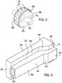
- FIG. 1is an isometric view of a color-coded roller clamp apparatus according to an embodiment of the disclosure.
- FIG. 2is an isometric view of an embodiment of the disclosure.
- FIG. 3is an isometric view of an embodiment of the disclosure.
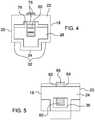
- FIG. 4is a front elevation view of an embodiment of the disclosure.
- FIG. 5is a rear elevation view of an embodiment of the disclosure.
- FIG. 6is a side elevation view of an embodiment of the disclosure.
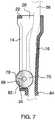
- FIG. 7is a cross-sectional view along line 6 - 6 of FIG. 1 an embodiment of the disclosure.
- FIGS. 1 through 7a new tube clamp embodying the principles and concepts of an embodiment of the disclosure and generally designated by the reference numeral 10 will be described.
- the color-coded roller clamp apparatus 10generally comprises a clamp housing 12 having a front side 14 , a back side 16 , a left side 18 , a right side 20 , a top side 22 , and a bottom side 24 defining a clamp inside 26 .
- a plus-shaped top aperture 28extends through the top side 22 to the clamp inside 26 .
- a roller slot 30extends through the front side 14 to the clamp inside 16 from proximal the top side 22 to proximal the bottom side 24 .
- the back side 16has a raised medial portion 34 and a pair of lateral portions 32 .
- the bottom side 24has a bottom aperture 36 extending through the medial portion 32 .
- the front side 14has a flared top front portion 38 adjacent the top side 22 , a ramped front portion 40 adjacent the top front portion 38 , and a straight bottom front portion 42 extending to the bottom side 24 .
- the lateral portions 32 of the back side 16each have a flared top lateral portion 44 adjacent the top side 22 , a ramped lateral portion 46 adjacent the top lateral portion 44 , and a straight bottom lateral portion 48 extending to the bottom side 24 .
- the medial portion 34 of the back side 16has a flared top medial portion 50 adjacent the top side 22 , a ramped medial portion 52 adjacent the top medial portion 50 , and an angled bottom medial portion 54 extending to, and angling down towards, the bottom side 24 .
- the clamp housing 12is configured to receive an IV tube 56 passing through the top aperture 28 and out the bottom aperture 36 along the medial portion 34 .
- a roller 58is coupled to the clamp housing 12 comprising a wheel 60 having a left face 62 , a right face 64 , and a perimeter face 66 .
- the flared top front portion 38 of the housing 12allows the roller 58 to move out of the way to insert or remove the IV tube 56 .
- Each of the left face 62 and the right face 64is chamfered adjacent the perimeter Ike 66 ,
- the wheel 60partially extends through the roller slot 30 .
- a first hemisphere 68 and a second hemisphere 70 of each of the left face 62 , the right face 64 , and the perimeter face 66is a first color and a second color, respectively.
- a plurality of ribs 76is coupled to the wheel 60 .
- the plurality of ribs 76is coupled to the perimeter face 66 .
- the plurality of ribs 76may be rounded and evenly spaced.
- the plurality of ribs 76add grip to better pinch the IV tube 56 .
- An axle 78is coupled to the wheel 60 and centrally extends through each of the left face 62 and the right face 64 .
- the axle 78is coupled within the clamp inside 26 between the front side 14 and the pair of lateral portions 32 of the back side 16 .
- the roller 58is rollingly moveable between a disengaged position 80 proximal the top side 22 and an alternative engaged position 82 proximal the bottom side 24 .
- the wheel 60 in the disengaged position 80exposes the first hemisphere 68 through the roller slot 30 and the wheel 60 in the engaged position 82 exposes the second hemisphere 70 through the roller slot 30 and is configured to clamp the IV tube 56 against the back side 16 to prevent flow.
- An annular stopper 84is elasticized and configured to fit onto the IV tube 56 to support the bottom side 24 of the clamp housing 12 .
- the usermoves the roller 58 between the disengaged position 80 and the engaged position 82 to expose the first hemisphere 68 as a first color and a second hemisphere 70 as a second color through the roller slot 30 .
- the first color and second colorallow the user to more easily see if contents are moving through the IV tube 56 .
Landscapes
- Health & Medical Sciences (AREA)
- Heart & Thoracic Surgery (AREA)
- Engineering & Computer Science (AREA)
- Animal Behavior & Ethology (AREA)
- Public Health (AREA)
- Biomedical Technology (AREA)
- Hematology (AREA)
- Life Sciences & Earth Sciences (AREA)
- Veterinary Medicine (AREA)
- General Health & Medical Sciences (AREA)
- Anesthesiology (AREA)
- Pulmonology (AREA)
- General Engineering & Computer Science (AREA)
- Vascular Medicine (AREA)
- Mechanical Engineering (AREA)
- Physics & Mathematics (AREA)
- Fluid Mechanics (AREA)
- Reduction Rolling/Reduction Stand/Operation Of Reduction Machine (AREA)
Abstract
Description
Claims (8)
Priority Applications (1)
| Application Number | Priority Date | Filing Date | Title |
|---|---|---|---|
| US16/528,770US11045637B2 (en) | 2019-08-01 | 2019-08-01 | Color-coded roller clamp apparatus |
Applications Claiming Priority (1)
| Application Number | Priority Date | Filing Date | Title |
|---|---|---|---|
| US16/528,770US11045637B2 (en) | 2019-08-01 | 2019-08-01 | Color-coded roller clamp apparatus |
Publications (2)
| Publication Number | Publication Date |
|---|---|
| US20210031025A1 US20210031025A1 (en) | 2021-02-04 |
| US11045637B2true US11045637B2 (en) | 2021-06-29 |
Family
ID=74258981
Family Applications (1)
| Application Number | Title | Priority Date | Filing Date |
|---|---|---|---|
| US16/528,770Active2039-10-09US11045637B2 (en) | 2019-08-01 | 2019-08-01 | Color-coded roller clamp apparatus |
Country Status (1)
| Country | Link |
|---|---|
| US (1) | US11045637B2 (en) |
Families Citing this family (2)
| Publication number | Priority date | Publication date | Assignee | Title |
|---|---|---|---|---|
| US12053613B2 (en)* | 2021-11-16 | 2024-08-06 | Carefusion 303, Inc. | Circular roller clamp assembly |
| CN113975534B (en)* | 2021-11-19 | 2022-04-12 | 常州市第一人民医院 | A flow regulator with needle fixing function |
Citations (11)
| Publication number | Priority date | Publication date | Assignee | Title |
|---|---|---|---|---|
| US3915167A (en) | 1974-05-23 | 1975-10-28 | Atlantic Design & Dev Corp | Intravenous clamp |
| US4406440A (en)* | 1980-03-25 | 1983-09-27 | Baxter Travenol Laboratories, Inc. | Flow regulating device |
| US4725037A (en)* | 1987-04-06 | 1988-02-16 | Marvin Adelberg | Shut-off mechanism for clamp for regulating flow through plastic tubing |
| US4895340A (en)* | 1987-11-17 | 1990-01-23 | Forberg Hans Juergen | Clamp for adjusting the throughflow cross-section of a tube, in particular for medical devices intended for once-only use |
| US5088990A (en) | 1989-08-30 | 1992-02-18 | Hivale Ronald S | I.V. alert system |
| US6406426B1 (en) | 1999-11-03 | 2002-06-18 | Criticare Systems | Medical monitoring and alert system for use with therapeutic devices |
| US20120283630A1 (en) | 2011-05-06 | 2012-11-08 | Chaoyoung Lee | Flow Control Line Management Apparatus |
| US8486019B2 (en) | 1999-12-01 | 2013-07-16 | B. Braun Medical, Inc. | Patient medication IV delivery pump with wireless communication to a hospital information management system |
| US9308323B2 (en) | 2011-11-15 | 2016-04-12 | Smiths Medical Asd, Inc. | Systems and methods for illuminated medical tubing detection and management indicating a characteristic of at least one infusion pump |
| CN108114340A (en)* | 2018-01-31 | 2018-06-05 | 无锡市人民医院 | A kind of low dose drainage-fluid flow diverter |
| US10072959B2 (en) | 2015-08-28 | 2018-09-11 | Crisi Medical Systems, Inc. | Flow sensor system with connection assembly |
- 2019
- 2019-08-01USUS16/528,770patent/US11045637B2/enactiveActive
Patent Citations (11)
| Publication number | Priority date | Publication date | Assignee | Title |
|---|---|---|---|---|
| US3915167A (en) | 1974-05-23 | 1975-10-28 | Atlantic Design & Dev Corp | Intravenous clamp |
| US4406440A (en)* | 1980-03-25 | 1983-09-27 | Baxter Travenol Laboratories, Inc. | Flow regulating device |
| US4725037A (en)* | 1987-04-06 | 1988-02-16 | Marvin Adelberg | Shut-off mechanism for clamp for regulating flow through plastic tubing |
| US4895340A (en)* | 1987-11-17 | 1990-01-23 | Forberg Hans Juergen | Clamp for adjusting the throughflow cross-section of a tube, in particular for medical devices intended for once-only use |
| US5088990A (en) | 1989-08-30 | 1992-02-18 | Hivale Ronald S | I.V. alert system |
| US6406426B1 (en) | 1999-11-03 | 2002-06-18 | Criticare Systems | Medical monitoring and alert system for use with therapeutic devices |
| US8486019B2 (en) | 1999-12-01 | 2013-07-16 | B. Braun Medical, Inc. | Patient medication IV delivery pump with wireless communication to a hospital information management system |
| US20120283630A1 (en) | 2011-05-06 | 2012-11-08 | Chaoyoung Lee | Flow Control Line Management Apparatus |
| US9308323B2 (en) | 2011-11-15 | 2016-04-12 | Smiths Medical Asd, Inc. | Systems and methods for illuminated medical tubing detection and management indicating a characteristic of at least one infusion pump |
| US10072959B2 (en) | 2015-08-28 | 2018-09-11 | Crisi Medical Systems, Inc. | Flow sensor system with connection assembly |
| CN108114340A (en)* | 2018-01-31 | 2018-06-05 | 无锡市人民医院 | A kind of low dose drainage-fluid flow diverter |
Non-Patent Citations (1)
| Title |
|---|
| CN108114340A1, Machine Translation, 2018 (Year: 2018).* |
Also Published As
| Publication number | Publication date |
|---|---|
| US20210031025A1 (en) | 2021-02-04 |
Similar Documents
| Publication | Publication Date | Title |
|---|---|---|
| USD887699S1 (en) | Bag | |
| USD885043S1 (en) | Pet carrier | |
| USD885190S1 (en) | Container | |
| USD883659S1 (en) | Pet carrier | |
| USD798861S1 (en) | Apparatus for recording, transmission or processing of information | |
| USD938694S1 (en) | Garment | |
| USD802156S1 (en) | Diagnostic analyzer | |
| USD918317S1 (en) | Exercise equipment | |
| Fall | Semilinear elliptic equations for the fractional Laplacian with Hardy potential | |
| USD893409S1 (en) | Battery device | |
| USD873151S1 (en) | Packaging | |
| USD1028726S1 (en) | Bottle | |
| USD854924S1 (en) | Package | |
| USD901782S1 (en) | Welding helmet | |
| USD921884S1 (en) | Catheter insertion device | |
| US11045637B2 (en) | Color-coded roller clamp apparatus | |
| USD914230S1 (en) | Medical apparatus | |
| USD838644S1 (en) | Automotive wheel | |
| US20190191910A1 (en) | Clothes Hanger Organization Assembly | |
| US11325227B2 (en) | Sprinkler head removal and installation device | |
| USD913886S1 (en) | Muffler filter | |
| USD933558S1 (en) | Pair of tailpipes | |
| USD882764S1 (en) | Injection device | |
| USD903193S1 (en) | Pouch | |
| USD945266S1 (en) | Cap |
Legal Events
| Date | Code | Title | Description |
|---|---|---|---|
| FEPP | Fee payment procedure | Free format text:ENTITY STATUS SET TO UNDISCOUNTED (ORIGINAL EVENT CODE: BIG.); ENTITY STATUS OF PATENT OWNER: MICROENTITY | |
| FEPP | Fee payment procedure | Free format text:ENTITY STATUS SET TO MICRO (ORIGINAL EVENT CODE: MICR); ENTITY STATUS OF PATENT OWNER: MICROENTITY | |
| STPP | Information on status: patent application and granting procedure in general | Free format text:NON FINAL ACTION MAILED | |
| STPP | Information on status: patent application and granting procedure in general | Free format text:RESPONSE TO NON-FINAL OFFICE ACTION ENTERED AND FORWARDED TO EXAMINER | |
| STPP | Information on status: patent application and granting procedure in general | Free format text:FINAL REJECTION MAILED | |
| STPP | Information on status: patent application and granting procedure in general | Free format text:RESPONSE AFTER FINAL ACTION FORWARDED TO EXAMINER | |
| STPP | Information on status: patent application and granting procedure in general | Free format text:NOTICE OF ALLOWANCE MAILED -- APPLICATION RECEIVED IN OFFICE OF PUBLICATIONS | |
| STPP | Information on status: patent application and granting procedure in general | Free format text:PUBLICATIONS -- ISSUE FEE PAYMENT RECEIVED | |
| STPP | Information on status: patent application and granting procedure in general | Free format text:PUBLICATIONS -- ISSUE FEE PAYMENT VERIFIED | |
| STCF | Information on status: patent grant | Free format text:PATENTED CASE | |
| MAFP | Maintenance fee payment | Free format text:PAYMENT OF MAINTENANCE FEE, 4TH YEAR, MICRO ENTITY (ORIGINAL EVENT CODE: M3551); ENTITY STATUS OF PATENT OWNER: MICROENTITY Year of fee payment:4 |