US11045626B2 - Guide wire device and method - Google Patents
Guide wire device and methodDownload PDFInfo
- Publication number
- US11045626B2 US11045626B2US15/448,299US201715448299AUS11045626B2US 11045626 B2US11045626 B2US 11045626B2US 201715448299 AUS201715448299 AUS 201715448299AUS 11045626 B2US11045626 B2US 11045626B2
- Authority
- US
- United States
- Prior art keywords
- needle
- guide wire
- marker clip
- sensing
- marker
- Prior art date
- Legal status (The legal status is an assumption and is not a legal conclusion. Google has not performed a legal analysis and makes no representation as to the accuracy of the status listed.)
- Expired - Fee Related, expires
Links
Images


Classifications
- A—HUMAN NECESSITIES
- A61—MEDICAL OR VETERINARY SCIENCE; HYGIENE
- A61M—DEVICES FOR INTRODUCING MEDIA INTO, OR ONTO, THE BODY; DEVICES FOR TRANSDUCING BODY MEDIA OR FOR TAKING MEDIA FROM THE BODY; DEVICES FOR PRODUCING OR ENDING SLEEP OR STUPOR
- A61M25/00—Catheters; Hollow probes
- A61M25/01—Introducing, guiding, advancing, emplacing or holding catheters
- A61M25/0105—Steering means as part of the catheter or advancing means; Markers for positioning
- A61M25/0108—Steering means as part of the catheter or advancing means; Markers for positioning using radio-opaque or ultrasound markers
- A—HUMAN NECESSITIES
- A61—MEDICAL OR VETERINARY SCIENCE; HYGIENE
- A61B—DIAGNOSIS; SURGERY; IDENTIFICATION
- A61B34/00—Computer-aided surgery; Manipulators or robots specially adapted for use in surgery
- A61B34/20—Surgical navigation systems; Devices for tracking or guiding surgical instruments, e.g. for frameless stereotaxis
- A—HUMAN NECESSITIES
- A61—MEDICAL OR VETERINARY SCIENCE; HYGIENE
- A61B—DIAGNOSIS; SURGERY; IDENTIFICATION
- A61B90/00—Instruments, implements or accessories specially adapted for surgery or diagnosis and not covered by any of the groups A61B1/00 - A61B50/00, e.g. for luxation treatment or for protecting wound edges
- A61B90/10—Instruments, implements or accessories specially adapted for surgery or diagnosis and not covered by any of the groups A61B1/00 - A61B50/00, e.g. for luxation treatment or for protecting wound edges for stereotaxic surgery, e.g. frame-based stereotaxis
- A61B90/11—Instruments, implements or accessories specially adapted for surgery or diagnosis and not covered by any of the groups A61B1/00 - A61B50/00, e.g. for luxation treatment or for protecting wound edges for stereotaxic surgery, e.g. frame-based stereotaxis with guides for needles or instruments, e.g. arcuate slides or ball joints
- A61B90/13—Instruments, implements or accessories specially adapted for surgery or diagnosis and not covered by any of the groups A61B1/00 - A61B50/00, e.g. for luxation treatment or for protecting wound edges for stereotaxic surgery, e.g. frame-based stereotaxis with guides for needles or instruments, e.g. arcuate slides or ball joints guided by light, e.g. laser pointers
- A—HUMAN NECESSITIES
- A61—MEDICAL OR VETERINARY SCIENCE; HYGIENE
- A61B—DIAGNOSIS; SURGERY; IDENTIFICATION
- A61B90/00—Instruments, implements or accessories specially adapted for surgery or diagnosis and not covered by any of the groups A61B1/00 - A61B50/00, e.g. for luxation treatment or for protecting wound edges
- A61B90/39—Markers, e.g. radio-opaque or breast lesions markers
- A—HUMAN NECESSITIES
- A61—MEDICAL OR VETERINARY SCIENCE; HYGIENE
- A61M—DEVICES FOR INTRODUCING MEDIA INTO, OR ONTO, THE BODY; DEVICES FOR TRANSDUCING BODY MEDIA OR FOR TAKING MEDIA FROM THE BODY; DEVICES FOR PRODUCING OR ENDING SLEEP OR STUPOR
- A61M25/00—Catheters; Hollow probes
- A61M25/01—Introducing, guiding, advancing, emplacing or holding catheters
- A61M25/0105—Steering means as part of the catheter or advancing means; Markers for positioning
- A—HUMAN NECESSITIES
- A61—MEDICAL OR VETERINARY SCIENCE; HYGIENE
- A61M—DEVICES FOR INTRODUCING MEDIA INTO, OR ONTO, THE BODY; DEVICES FOR TRANSDUCING BODY MEDIA OR FOR TAKING MEDIA FROM THE BODY; DEVICES FOR PRODUCING OR ENDING SLEEP OR STUPOR
- A61M25/00—Catheters; Hollow probes
- A61M25/01—Introducing, guiding, advancing, emplacing or holding catheters
- A61M25/09—Guide wires
- A61M25/09041—Mechanisms for insertion of guide wires
- A—HUMAN NECESSITIES
- A61—MEDICAL OR VETERINARY SCIENCE; HYGIENE
- A61B—DIAGNOSIS; SURGERY; IDENTIFICATION
- A61B10/00—Instruments for taking body samples for diagnostic purposes; Other methods or instruments for diagnosis, e.g. for vaccination diagnosis, sex determination or ovulation-period determination; Throat striking implements
- A61B10/02—Instruments for taking cell samples or for biopsy
- A61B10/04—Endoscopic instruments, e.g. catheter-type instruments
- A61B2010/045—Needles
- A—HUMAN NECESSITIES
- A61—MEDICAL OR VETERINARY SCIENCE; HYGIENE
- A61B—DIAGNOSIS; SURGERY; IDENTIFICATION
- A61B17/00—Surgical instruments, devices or methods
- A61B2017/00017—Electrical control of surgical instruments
- A61B2017/00022—Sensing or detecting at the treatment site
- A61B2017/00057—Light
- A—HUMAN NECESSITIES
- A61—MEDICAL OR VETERINARY SCIENCE; HYGIENE
- A61B—DIAGNOSIS; SURGERY; IDENTIFICATION
- A61B17/00—Surgical instruments, devices or methods
- A61B2017/00017—Electrical control of surgical instruments
- A61B2017/00022—Sensing or detecting at the treatment site
- A61B2017/00106—Sensing or detecting at the treatment site ultrasonic
- A—HUMAN NECESSITIES
- A61—MEDICAL OR VETERINARY SCIENCE; HYGIENE
- A61B—DIAGNOSIS; SURGERY; IDENTIFICATION
- A61B17/00—Surgical instruments, devices or methods
- A61B2017/00017—Electrical control of surgical instruments
- A61B2017/00115—Electrical control of surgical instruments with audible or visual output
- A—HUMAN NECESSITIES
- A61—MEDICAL OR VETERINARY SCIENCE; HYGIENE
- A61B—DIAGNOSIS; SURGERY; IDENTIFICATION
- A61B17/00—Surgical instruments, devices or methods
- A61B2017/00017—Electrical control of surgical instruments
- A61B2017/00221—Electrical control of surgical instruments with wireless transmission of data, e.g. by infrared radiation or radiowaves
- A—HUMAN NECESSITIES
- A61—MEDICAL OR VETERINARY SCIENCE; HYGIENE
- A61B—DIAGNOSIS; SURGERY; IDENTIFICATION
- A61B17/00—Surgical instruments, devices or methods
- A61B2017/00681—Aspects not otherwise provided for
- A61B2017/00734—Aspects not otherwise provided for battery operated
- A—HUMAN NECESSITIES
- A61—MEDICAL OR VETERINARY SCIENCE; HYGIENE
- A61B—DIAGNOSIS; SURGERY; IDENTIFICATION
- A61B17/00—Surgical instruments, devices or methods
- A61B2017/00743—Type of operation; Specification of treatment sites
- A61B2017/00796—Breast surgery
- A61B2017/008—Removal of tumors
- A—HUMAN NECESSITIES
- A61—MEDICAL OR VETERINARY SCIENCE; HYGIENE
- A61B—DIAGNOSIS; SURGERY; IDENTIFICATION
- A61B34/00—Computer-aided surgery; Manipulators or robots specially adapted for use in surgery
- A61B34/20—Surgical navigation systems; Devices for tracking or guiding surgical instruments, e.g. for frameless stereotaxis
- A61B2034/2046—Tracking techniques
- A61B2034/2063—Acoustic tracking systems, e.g. using ultrasound
- A—HUMAN NECESSITIES
- A61—MEDICAL OR VETERINARY SCIENCE; HYGIENE
- A61B—DIAGNOSIS; SURGERY; IDENTIFICATION
- A61B90/00—Instruments, implements or accessories specially adapted for surgery or diagnosis and not covered by any of the groups A61B1/00 - A61B50/00, e.g. for luxation treatment or for protecting wound edges
- A61B90/06—Measuring instruments not otherwise provided for
- A61B2090/062—Measuring instruments not otherwise provided for penetration depth
- A—HUMAN NECESSITIES
- A61—MEDICAL OR VETERINARY SCIENCE; HYGIENE
- A61B—DIAGNOSIS; SURGERY; IDENTIFICATION
- A61B90/00—Instruments, implements or accessories specially adapted for surgery or diagnosis and not covered by any of the groups A61B1/00 - A61B50/00, e.g. for luxation treatment or for protecting wound edges
- A61B90/06—Measuring instruments not otherwise provided for
- A61B2090/067—Measuring instruments not otherwise provided for for measuring angles
- A—HUMAN NECESSITIES
- A61—MEDICAL OR VETERINARY SCIENCE; HYGIENE
- A61B—DIAGNOSIS; SURGERY; IDENTIFICATION
- A61B90/00—Instruments, implements or accessories specially adapted for surgery or diagnosis and not covered by any of the groups A61B1/00 - A61B50/00, e.g. for luxation treatment or for protecting wound edges
- A61B90/30—Devices for illuminating a surgical field, the devices having an interrelation with other surgical devices or with a surgical procedure
- A61B2090/309—Devices for illuminating a surgical field, the devices having an interrelation with other surgical devices or with a surgical procedure using white LEDs
- A—HUMAN NECESSITIES
- A61—MEDICAL OR VETERINARY SCIENCE; HYGIENE
- A61B—DIAGNOSIS; SURGERY; IDENTIFICATION
- A61B90/00—Instruments, implements or accessories specially adapted for surgery or diagnosis and not covered by any of the groups A61B1/00 - A61B50/00, e.g. for luxation treatment or for protecting wound edges
- A61B90/39—Markers, e.g. radio-opaque or breast lesions markers
- A61B2090/3904—Markers, e.g. radio-opaque or breast lesions markers specially adapted for marking specified tissue
- A61B2090/3908—Soft tissue, e.g. breast tissue
- A—HUMAN NECESSITIES
- A61—MEDICAL OR VETERINARY SCIENCE; HYGIENE
- A61B—DIAGNOSIS; SURGERY; IDENTIFICATION
- A61B90/00—Instruments, implements or accessories specially adapted for surgery or diagnosis and not covered by any of the groups A61B1/00 - A61B50/00, e.g. for luxation treatment or for protecting wound edges
- A61B90/39—Markers, e.g. radio-opaque or breast lesions markers
- A61B2090/3925—Markers, e.g. radio-opaque or breast lesions markers ultrasonic
- A61B2090/3929—Active markers
- A—HUMAN NECESSITIES
- A61—MEDICAL OR VETERINARY SCIENCE; HYGIENE
- A61B—DIAGNOSIS; SURGERY; IDENTIFICATION
- A61B90/00—Instruments, implements or accessories specially adapted for surgery or diagnosis and not covered by any of the groups A61B1/00 - A61B50/00, e.g. for luxation treatment or for protecting wound edges
- A61B90/39—Markers, e.g. radio-opaque or breast lesions markers
- A61B2090/3937—Visible markers
- A61B2090/3945—Active visible markers, e.g. light emitting diodes
- A—HUMAN NECESSITIES
- A61—MEDICAL OR VETERINARY SCIENCE; HYGIENE
- A61B—DIAGNOSIS; SURGERY; IDENTIFICATION
- A61B90/00—Instruments, implements or accessories specially adapted for surgery or diagnosis and not covered by any of the groups A61B1/00 - A61B50/00, e.g. for luxation treatment or for protecting wound edges
- A61B90/39—Markers, e.g. radio-opaque or breast lesions markers
- A61B2090/3966—Radiopaque markers visible in an X-ray image
- A—HUMAN NECESSITIES
- A61—MEDICAL OR VETERINARY SCIENCE; HYGIENE
- A61B—DIAGNOSIS; SURGERY; IDENTIFICATION
- A61B90/00—Instruments, implements or accessories specially adapted for surgery or diagnosis and not covered by any of the groups A61B1/00 - A61B50/00, e.g. for luxation treatment or for protecting wound edges
- A61B90/39—Markers, e.g. radio-opaque or breast lesions markers
- A61B2090/397—Markers, e.g. radio-opaque or breast lesions markers electromagnetic other than visible, e.g. microwave
- A61B2090/3975—Markers, e.g. radio-opaque or breast lesions markers electromagnetic other than visible, e.g. microwave active
- A61B2090/3979—Markers, e.g. radio-opaque or breast lesions markers electromagnetic other than visible, e.g. microwave active infrared
- A—HUMAN NECESSITIES
- A61—MEDICAL OR VETERINARY SCIENCE; HYGIENE
- A61B—DIAGNOSIS; SURGERY; IDENTIFICATION
- A61B90/00—Instruments, implements or accessories specially adapted for surgery or diagnosis and not covered by any of the groups A61B1/00 - A61B50/00, e.g. for luxation treatment or for protecting wound edges
- A61B90/39—Markers, e.g. radio-opaque or breast lesions markers
- A61B2090/3987—Applicators for implanting markers
- A—HUMAN NECESSITIES
- A61—MEDICAL OR VETERINARY SCIENCE; HYGIENE
- A61B—DIAGNOSIS; SURGERY; IDENTIFICATION
- A61B90/00—Instruments, implements or accessories specially adapted for surgery or diagnosis and not covered by any of the groups A61B1/00 - A61B50/00, e.g. for luxation treatment or for protecting wound edges
- A61B90/39—Markers, e.g. radio-opaque or breast lesions markers
- A61B2090/3995—Multi-modality markers
- A—HUMAN NECESSITIES
- A61—MEDICAL OR VETERINARY SCIENCE; HYGIENE
- A61B—DIAGNOSIS; SURGERY; IDENTIFICATION
- A61B90/00—Instruments, implements or accessories specially adapted for surgery or diagnosis and not covered by any of the groups A61B1/00 - A61B50/00, e.g. for luxation treatment or for protecting wound edges
- A61B90/90—Identification means for patients or instruments, e.g. tags
- A61B90/98—Identification means for patients or instruments, e.g. tags using electromagnetic means, e.g. transponders
- A—HUMAN NECESSITIES
- A61—MEDICAL OR VETERINARY SCIENCE; HYGIENE
- A61M—DEVICES FOR INTRODUCING MEDIA INTO, OR ONTO, THE BODY; DEVICES FOR TRANSDUCING BODY MEDIA OR FOR TAKING MEDIA FROM THE BODY; DEVICES FOR PRODUCING OR ENDING SLEEP OR STUPOR
- A61M25/00—Catheters; Hollow probes
- A61M25/01—Introducing, guiding, advancing, emplacing or holding catheters
- A61M25/0105—Steering means as part of the catheter or advancing means; Markers for positioning
- A61M2025/0166—Sensors, electrodes or the like for guiding the catheter to a target zone, e.g. image guided or magnetically guided
- A—HUMAN NECESSITIES
- A61—MEDICAL OR VETERINARY SCIENCE; HYGIENE
- A61M—DEVICES FOR INTRODUCING MEDIA INTO, OR ONTO, THE BODY; DEVICES FOR TRANSDUCING BODY MEDIA OR FOR TAKING MEDIA FROM THE BODY; DEVICES FOR PRODUCING OR ENDING SLEEP OR STUPOR
- A61M25/00—Catheters; Hollow probes
- A61M25/01—Introducing, guiding, advancing, emplacing or holding catheters
- A61M25/09—Guide wires
- A61M2025/09116—Design of handles or shafts or gripping surfaces thereof for manipulating guide wires
- A—HUMAN NECESSITIES
- A61—MEDICAL OR VETERINARY SCIENCE; HYGIENE
- A61M—DEVICES FOR INTRODUCING MEDIA INTO, OR ONTO, THE BODY; DEVICES FOR TRANSDUCING BODY MEDIA OR FOR TAKING MEDIA FROM THE BODY; DEVICES FOR PRODUCING OR ENDING SLEEP OR STUPOR
- A61M25/00—Catheters; Hollow probes
- A61M25/01—Introducing, guiding, advancing, emplacing or holding catheters
- A61M25/09—Guide wires
- A61M2025/09166—Guide wires having radio-opaque features
Definitions
- the present inventionrelates to deploying a guide wire prior to a lumpectomy procedure.
- Biopsy sampleshave been obtained in a variety of ways with various medical devices.
- An example biopsy deviceis disclosed in U.S. Pub. No. 2013/0245493, entitled “Clutch and Valving System for Tetherless Biopsy Device”, published Sep. 19, 2013.
- Biopsy marker clipshave been deployed in a variety of ways with various medical devices.
- An example marker clip deployment deviceis disclosed in U.S. Pub. No. 2013/0237912, entitled “Biopsy Marker Delivery Device”, published Sep. 12, 2013.
- the goal of the clip marker deploymentis to place the clip marker as accurately as possible to the site where the tissue sample was removed. After the tissue sample is tested, it may be determined that a lumpectomy procedure is required.
- the goal of the lumpectomy procedureis to remove a section of tissue with an adequate margin distance centered about the marker clip.
- a guide wireis inserted into the breast. This guide wire insertion procedure is done in the radiology suite. Using multiple views, the radiologist positions the guide wire tip slightly past the clip marker.
- the tail of the guide wire exiting the breastis secured with tape and care must be taken to not disturb the guide wire prior to the lumpectomy procedure.
- the present inventionincorporates a smart clip marker with sensors and wireless transmission capability.
- This smart clip markercould be inserted in the same manner as outlined in U.S. Pub. No. 2013/0237912.
- the surgeonwould insert the guide wire using a wireless handheld insertion device.
- the wireless communication between the handheld insertion device and the smart clip markerwould eliminate the need for any radiology imaging during the guide wire insertion.
- the surgeonwould then proceed with the lumpectomy using the guide wire for localization to the marker clip position.
- the directional guidance of the handheld insertion devicewould be accomplished with light sensing on the smart marker clip. Multiple light emitters on the handheld insertion device would provide both angular indication and magnitude of misalignment.
- the smart marker clipwould sense and transmit when the ultrasonic signal arrives. The amount of time for the signal to arrive would allow a marker clip distance to be calculated and displayed on the handheld insertion device.
- the handheld devicealso has a probe to allow distance measurements to be taken during the lumpectomy procedure. These measurements provide better margin control during the procedure.
- the handheld device with probeAfter the specimen has been removed, the handheld device with probe would be used to verify the clip marker is within the specimen. The correct margins around the clip marker would also be verified.
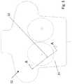
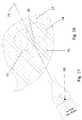
- FIG. 1is an AP (anterior posterior) view of a patient outline.
- FIG. 2is a section view of a breast taken along section line A-A from FIG. 1 .
- FIG. 3is a side view of a marker clip
- FIG. 4is an end view of a marker clip.
- FIG. 5is a section view of a marker clip taken along section line B-B from FIG. 3 .
- FIG. 6is a block diagram of the marker clip electronic components.
- FIG. 7is a side view of a deployment handheld.
- FIG. 8is a top view of a deployment handheld.
- FIG. 9is a enlarged end view of the deployment handheld taken from view line C-C from FIG. 7 .
- FIG. 10is a enlarged end view of the deployment handheld taken from view line D-D from FIG. 7 .
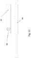
- FIG. 11is a side view of a separated deployment handheld.
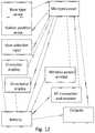
- FIG. 12is a block diagram of the deployment handheld electronic components.
- FIG. 13is an AP view of a patient outline with a deployment handheld in position.
- FIG. 14is a section view of breast with wide light pattern taken along section line F-F from FIG. 13 .
- FIG. 15is a close up top view of the off target display taken from FIG. 13 .
- FIG. 16is a section view of a breast with on target wide light pattern.
- FIG. 17is a close up top view of the approaching target display.
- FIG. 18is a section view of a breast with on target narrow light pattern.
- FIG. 19is a close up top view of the on target display.
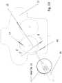
- FIG. 20is a section view of the deployment handheld taken along section line E-E from FIG. 8 .
- FIG. 21is a close up section view of the holder taken from FIG. 20 .
- FIG. 22is a close up section view of the needle tip taken from FIG. 21 .
- FIG. 23is a close up section view of the light pipe taken from FIG. 20 .
- FIG. 24is a close up section view of the button spool taken from FIG. 20 .
- FIG. 25is a close up section view of the spool wire taken from FIG. 24 .
- FIG. 26is a section view of the deployment handheld with the holder partially retracted.
- FIG. 27is a close up section view of the holder taken from FIG. 26 .
- FIG. 28is a section view of the deployment handheld with the button spool depressed.
- FIG. 29is a close up section view of the button spool taken from FIG. 28 .
- FIG. 30is a close up section view of the guide wire tip taken from FIG. 28 .
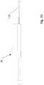
- FIG. 31is a side view of the deployment handheld with a extended button spool.
- FIG. 32is a modification of FIG. 28 with extended button spool.
- FIG. 33is a close up section view of the extended button spool taken from FIG. 32 .
- FIG. 34is a side view of a separated clip distance handheld.
- FIG. 35is a side view of a clip distance handheld.
- FIG. 36is a close up section view of the clip distance handheld tip taken along section line G-G from FIG. 35 .
- FIG. 37is a close up section view of the clip distance handheld flexible tip.
- FIG. 38is a close up section view of the clip distance handheld flexible tip in a bent position.
- FIG. 1is a an AP (anterior posterior) view of a patient outline.
- the patient 12is supine.
- the marker clip 15would have previously been placed in the breast 14 .
- This viewshows the X and Y position of the marker clip 15 .
- FIG. 2is a section view of a breast taken along section line A-A from FIG. 1 . This view shows the Z position of the marker clip 15 .
- FIG. 3is a side view of a marker clip.
- the size of the marker clip 15would be approximately 2 mm by 10 mm.
- the marker clip 15When placed in the breast 14 , the marker clip 15 would have pledgets attached to each end. Each pledget would be approximately 2 mm by ⁇ 10 mm.
- the purpose of the pledgetis to improve the attachment of the marker clip 15 to surrounding tissue and resist movement of the marker clip 15 within the breast 14 .
- the pledgetwould be constructed of a material that is translucent to light such as collagen.
- the pledgetwould also be constructed in a fibrous manner to provide pathways for light transmission. The pledget is not shown in any of the views of the marker clip 15 .
- the marker clip 15has a hexagon shape. This is to provide six flat surfaces on the sides for placement of photo cells 20 - 25 .
- FIG. 4is an end view of a marker clip.
- One end of the marker clip 15includes photocell 26 and the other end photocell 27 .
- FIG. 5is a section view of a marker clip taken along section line B-B from FIG. 3 .
- the marker clip 15includes an image bar 30 to facilitate location with existing imaging techniques such as x-ray or Mill.
- the image bar 30 materialwould be stainless steel or a similar imaging opaque material.
- Several shapes of the image bar 30would be possible to allow multiple marker clips 15 to be individually identified. These shapes could include as shown in FIG. 3 and also an L or a U. Different lengths on the legs of the image bar 30 would provide more variations.
- the image bar 30also provides a rigid structure for the marker clip 15 . After the internal marker clip 15 components are in place, the potting compound 32 is added. The sealant 34 is then added to provide a clear nonpervious surface for the marker clip 15 .
- the micro components 31include several devices. These devices would include the microprocessor, ultrasonic sensor, wireless power receiver, radio frequency transmitter/receiver, and the capacitor power supply. If possible, it would be desirable from a cost point of view for all these devices to be surface mounted on a circuit board. This circuit board would be placed in the marker clip 15 in the position shown as micro components 31 . Discrete lead wires would then be attached from the circuit board to each of the photocells.
- microprocessor die cutmay be used.
- Each of the other deviceswill be discrete silicon die cuts or micro components.
- Individual gold lead wireswill be welded from die to device.
- the microprocessor die cutit may be necessary for the microprocessor die cut to be rectangular in shape.
- An example die sizemay be 1 mm by 4 mm. A custom microprocessor mask with circuits in this rectangular shape would allow this.
- FIG. 6is a block diagram of the marker clip electronic components.
- a wireless power emitter 66is part of the deployment handheld 36 .
- the wireless power receiveris tuned to the emitter 66 frequency.
- the capacitor power supplyregulates the voltage and smooths any short term power interruptions.
- the ultrasonic sensorcould be a piezoelectric device or capacitive micromachined ultrasonic transducer (CMUT). Although ultrasonic would be preferred, an audio range sound sensor could be utilized. If an audio range sound sensor was utilized, the holder ultrasonic 77 would be replaced with a holder audio range emitter. Also the probe ultrasonic 104 would be replaced with a probe audio range emitter.
- sonicshall inclusively refer to ultrasonic and audio range.
- the radio frequency (RF) transmitter and receiverprovide the capability for the marker clip to digitally communicate with the deployment handheld 36 .
- the photocell sensorscould be photodiodes operating in photovoltaic mode.
- the key parameteris high sensitivity.
- FIG. 7is a side view of a deployment handheld.
- the deployment handheld 36includes a holder 40 which is fixed to the left pushrod 41 and the right pushrod 43 .
- the button spool 50which is used to deploy the guide wire 79 .
- FIG. 8is a top view of a deployment handheld. This view shows the pushrods 41 , 43 and the needle assembly 42 .
- the needle assembly 42does not move relative to the deployment handheld 36 .
- the holder 40 and pushrods 41 , 42can move toward the deployment handheld 36 when the pushrod release 48 is depressed.
- the directional display 44is used to show the relative alignment of the needle assembly 42 to the marker clip 15 position.
- the character display 45is used to indicate the identification number of the marker clip 15 and distance from the guide wire 79 to the marker clip 15 .
- the user input 46is to allow the operator to select from the character display. It could include up/down inputs with rocking action and select input with push action.
- FIG. 9is an enlarged end view of the deployment handheld taken from view line C-C from FIG. 7 .
- the needle assembly 42is visible from an opening in the holder 40 .
- Six LEDs (light-emitting diode) 53 - 62are shown. These LEDs are used to transmit light through the breast 14 tissue.
- the near infrared (NIR) window for breast tissue transmissionis 626 to 1316 nm.
- An LED light wavelength of 730 nmis optimal for this transmission.
- LEDshave been identified, alternate constructions of light emitters would provide function to the apparatus. Other types of light emitters include incandescent bulb, gas-discharge lamp and laser.
- LED A 53 , LED B 54 and LED C 55are the wide angle light transmitters. These LEDs would have a power of 1000 mW and total beam angle of 25 degrees.
- LED D 60 , LED E 61 and LED F 62are the narrow angle light transmitters. These LEDS would have a power of 500 mW and total beam angle of 10 degrees. These power ratings are constant duty and normal life. Due to this application having short duty cycle and limited life requirement, the LEDs could be overpowered by a factor of two or more.
- FIG. 10is a enlarged end view of the deployment handheld taken from view line D-D from FIG. 7 . This end view shows the position of the button spool 50 .
- FIG. 11is a side view of a separated deployment handheld.
- the deployment handheld 36is a combination of two devices. All patient contact is limited to the deployment assembly 65 which is a disposable device. As much as possible, the high cost electronics are included in the upper handle 64 which is reusable.
- the upper handle 64 and the deployment assembly 65would be easily connected with a snap fit. This connection would include any needed electrical and mechanical contact points.
- the wireless power emitter 66is shown as part of the upper handle 64 .
- the wireless power transmission systemwould use near field inductive coupling.
- FIG. 12is a block diagram of a deployment handheld electronic components.
- the base type sense and holder 40 position sensewould be electrical signals coming from the deployment assembly 65 . These signals would cross from the deployment assembly 65 to the upper handle 64 via electrical contacts.
- the base type sensewould communicate that a deployment assembly 65 is attached to the upper handle 64 .
- the deployment assembly 65would include a sensor for holder 40 position.
- FIG. 13is an AP view of a patient outline with a deployment handheld in position. Following are the initial steps of the guide wire placement procedure—
- FIG. 14is a section view of breast with wide light pattern taken along section line F-F from FIG. 13 . Following are the steps of the deployment handheld 36 alignment procedure—
- the LED shine outlineincludes the scattered light that is within the photocell sensitivity range.
- FIG. 15is a close up top view of the off target display taken from FIG. 13 .
- FIG. 15shows the display per the FIG. 14 light outlines.
- the alignment line 70shows the alignment of the deployment device 36 from FIG. 15 projected on to FIG. 14 .
- the marker clip 15 ID numberis shown in the character display 45 .
- the distance from the tip ultrasonic 85 to the marker clip 15is shown in the character display 45 .
- the marker spot 68shows the magnitude and angular orientation of the deployment handheld 36 misalignment relative to the marker clip 15 . Because LED B shine outline 74 was the only response, the marker spot 68 is indicated as shown just inside the 3 rd circle and in the angular direction of the LED B shine outline 74 .
- FIG. 16is a section view of a breast with on target wide light pattern. After the surgeon views the FIG. 15 display, the surgeon adjusts the deployment handheld 36 alignment resulting in the FIG. 16 light pattern. For this scan, all three LED outlines 73 - 75 are sensed by the marker clip 15 .
- FIG. 17is a close up top view of the approaching target display.
- FIG. 17shows the display per the FIG. 16 light outlines.
- the alignment line 71shows the alignment of the deployment device 36 from FIG. 17 projected on to FIG. 16 .
- the handheld device 36now switches to the narrow light pattern of LEDs 60 - 62 .
- An LED energizing sequence similar to LEDs 53 - 55is now employed for LEDs 60 - 62 .
- LED D 60was sensed by the marker clip 15 .
- LED D shine outline 78was the only response, the marker spot 68 is indicated as shown just inside the 2 rd circle and in the angular direction of the LED D shine outline 78 .
- FIG. 18is a section view of a breast with on target narrow light pattern. After the surgeon views the FIG. 17 display, the surgeon adjusts the deployment handheld 36 alignment resulting in the FIG. 18 light pattern. For this scan, all three LED outlines 78 , 84 and 87 are sensed by the marker clip 15 .
- FIG. 19is a close up top view of the on target display.
- FIG. 19shows the display per the FIG. 18 light outlines.
- the alignment line 72shows the alignment of the deployment device 36 from FIG. 19 projected on to FIG. 18 . Because all three LED outlines 78 , 84 and 87 are sensed by the marker clip, the marker spot 68 is indicated as shown inside the 1 st circle.
- the handheld device 36is now properly aligned and ready for needle assembly 42 insertion into the breast 14 .
- FIG. 20is a section view of the deployment handheld taken along section line E-E from FIG. 8 . Shown in this view are the holder 40 , light pipe LED G 92 , and button spool 50 . Note that some parts such as the upper handle 64 and the deployment assembly 65 are shown only in outline rather than cross section.
- FIG. 21is a close up section view of the holder taken from FIG. 20 . Shown in this view are LED A 53 and LED E 61 . Also shown is the right pushrod 43 and needle assembly 42 .
- the holder ultrasonic 77could be a piezoelectric or speaker device and is mounted inside the holder 40 . The purpose of the holder ultrasonic 77 is to transmit an ultrasonic pulse to the breast 14 . Since the holder 40 is pressed against the breast 14 , the surface to surface transmission loss will be small. If needed, air holes could be located within the holder 40 from the holder ultrasonic 77 to the breast 14 contact surface.
- All of the wiring for the holder 40would route through the right pushrod 43 . After exiting the end of the right pushrod 43 , extra wire and space would be provided to allow the right pushrod 43 to retract into the deployment assembly 65 .
- FIG. 22is a close up section view of the needle tip taken from FIG. 21 .
- the needle assembly 42includes the needle 88 , light pipes 82 , 83 and 89 , and guide wire 79 .
- the needle 88is made from stainless steel and is sharp to facilite insertion into the breast 14 .
- Surrounding the needle 88are light pipes 82 , 83 and 89 . These light pipes are shown in end view in FIG. 9 .
- Light pipes 82 , 83 and 89could be incorporated as either of two purposes:
- LEDs 60 - 62could be used as an alternate construction rather than LEDs 60 - 62 .
- the guide wire 79is made from a metallic alloy material and is sharp to facilite insertion into the breast 14 .
- the guide wire hook 80is shown in the stored position.
- the tip ultrasonic 85is a piezoelectric device attached to the guide wire 79 .
- the purpose of the tip ultrasonic 85is to provide greater accuracy for distance to the marker clip 15 rather than the holder ultrasonic 77 .
- the tip ultrasonic 85would not be enabled until the needle 88 has been inserted into the breast 14 . Due to the limited power of the tip ultrasonic 85 , the marker clip 15 would only be able to sense this device at short range.
- the deployment handheld 36would ignore the holder ultrasonic 77 signal, and instead display distance utilizing the tip ultrasonic 86 .
- the ultrasonic wire 86is a two conductor insulated wire that is positioned inside the guide wire 79 .
- the two conductorswould be attached to the tip ultrasonic 85 .
- the ultrasonic wire 86could be a single conductor insulated wire if the guide wire 79 was made from an electrically conductive material such as a metallic alloy. In this case, the guide wire 79 would be the second conductor. The tip ultrasonic 85 would be electrically connected to the guide wire 79 and the ultrasonic wire 86 .
- FIG. 23is a close up section view of the light pipe taken from FIG. 20 .
- Light pipe LED G 92is shown in position to shine into light pipe G 82 .
- the other two light pipeswould utilize similar LED shine construction.
- the pushrod brake 90is shown adjacent the right pushrod 43 .
- the holder 40 and pushrods 41 , 43retract into the deployment assembly 65 .
- the pushrod brake 90 in the engaged position as shownresist this movement.
- the pushrod release 48 button as shown in FIG. 8is depressed by the surgeon, the pushrod brake 90 moves to the release position and the holder 40 is free to move. This actuation between the pushrod release 48 and the pushrod brake 90 would cross the gap between the upper handle 64 and the deployment assembly 65 as a mechanical linkage.
- FIG. 24is a close up section view of the button spool taken from FIG. 20 . After the needle 88 has been fully inserted into the breast the proper distance, the surgeon would depress the button spool 50 to insert the guide wire 79 into the breast 14 . Note the needle end 95 of the needle 88 .
- the ultrasonic wire end 96would have extra wire and space to allow button spool 50 travel.
- FIG. 25is a close up section view of the spool wire taken from FIG. 24 .
- the guide wire end 81abuts the button spool shoulder 98 . This provides the forcing surface to move the guide wire 79 forward when the button spool 50 is depressed.
- FIG. 26is a section view of the deployment handheld with the holder partially retracted. The surgeon has pressed the pushrod release 48 to allow the holder 40 movement. The deployment assembly 65 has internal space to allow the pushrod end 99 clearance.
- LVDTlinear variable displacement transducer
- FIG. 27is a close up section view of the holder taken from FIG. 26 . This view shows the light pipes 82 , 33 and needle 88 exposed with the holder 40 retracted. The light pipes 82 , 83 , 89 and needle 88 are permanently attached to the deployment assembly 65 .
- FIG. 28is a section view of the deployment handheld with the button spool depressed. Note that the holder 40 has been further retracted. This retraction would be the amount of distance from the surface of the breast 14 to the marker clip 15 location. The button spool 50 has been depressed resulting in the forward movement of the guide wire 79 .
- FIG. 29is a close up section view of the button spool taken from FIG. 28 .
- the button spool 50has been depressed until it comes in contact with the deployment assembly 65 .
- FIG. 30is a close up section view of the guide wire tip taken from FIG. 28 .
- the guide wire hook 80is now in the deployed position.
- the extended guide wire hook 80would engage the breast 14 tissue to resist backward movement of the guide wire 79 .
- the next step in the procedurewould be for the surgeon to pull the deployment assembly 65 backward causing the needle 88 to exit the breast 14 .
- the guide wire 79would slide within the needle 88 .
- the ultrasonic wire 86would unwind within the button spool 50 and extend into the needle 88 .
- the final distance of the guide wire 79 to the marker clipcan be checked with still functioning tip ultrasonic 85 .
- the last step of the procedurewould be to cut the ultrasonic wire 86 and tape the loose end of the guide wire 79 outside the breast 14 .
- FIG. 31is a side view of the deployment handheld with an extended button spool. This is an alternate construction to the button spool 50 .
- the extended button spool 110provides a pushing force on the guide wire 79 during the entire extraction of the needle 88 from the breast 14 . This construction does not rely on the guide wire hook 80 pulling on the breast 14 tissue to cause guide wire 79 extraction from the needle 88 .
- FIG. 32is a modification of FIG. 28 with extended button spool. This view is from the same section lines as FIG. 28 but with the alternate extended button spool 110 construction. Note from this view, the approximate 100 mm length of guide wire 79 exposed past the end of the needle 88 . This length would provide full extraction of the needle 88 from the breast 14 and allow sufficient room for the surgeon to grasp the exposed guide wire 79 . After grasping the exposed guide wire 79 , the remainder of the guide wire 79 would be pulled through the needle 88 by continued retraction of the deployment handheld 36 .
- FIG. 33is a close up section view of the extended button spool taken from FIG. 32 . Note the overlap of the pushrod end 99 and the extended button spool 110 . The pushrods 41 , 43 would be relieved for this overlap distance to allow the extended button spool 110 movement.
- a length of ultrasonic wire 86would be coiled in the wire storage 114 area. This would allow the ultrasonic wire 86 to uncoil as the extended button spool 110 is depressed.
- the optimal distance from tip ultrasonic 85 to the marker clip 15is zero. To aid the surgeon, it is desirable for the guide wire 79 tip to be at the biopsy margin distance from the marker clip 15 . If the desired biopsy margin distance is 10 mm, the tip ultrasonic 85 would be placed 10 mm from the guide wire 79 tip.
- 10 mmis a standard margin distance. If a larger margin distance is desired (such as 15 mm), the following two adjustments would be followed.
- step (b)the insertion would be stopped when the distance indicates 0 mm.
- step (d)depression of the extended button spool 110 would cease when the distance reaches 5 mm.
- the preferred embodiment of the deployment handheld 36includes the holder 40 LEDs 53 - 55 , 60 - 62 ; and the extended button spool 110 .
- FIG. 34is a side view of a separated distance handheld. After the placement of the guide wire 79 , the upper handle 64 would be separated from the deployment assembly 65 . The upper handle 64 would then be attached to the clip distance assembly 101 . As long as the upper handle 64 has not been powered down, it will remain paired with the marker clip 15 .
- FIG. 35is a side view of a distance handheld.
- FIG. 36is a close up section view of the distance handheld tip taken along section line G-G from FIG. 35 .
- the probe 102is permanently fixed to clip distance assembly 101 .
- the probe ultrasonic 104a piezoelectric ultrasonic emitter, is located near the end of the probe 102 .
- the probe ultrasonic wires 120are connected to the probe ultrasonic 104 and the clip distance assembly 101 .
- probe openings 122are provided at the tip of the probe 102 . These probe openings 122 are to allow air transmission of the ultrasonic sound in the case when the probe 102 is not in direct contact with breast 14 tissue or the specimen.
- the function of the clip distance handheld 106is to provide a readout of the distance from the marker clip 15 to the probe ultrasonic 104 . It would use the same measurement methodology as the deployment handheld 36 .
- FIG. 37is a close up section view of the clip distance handheld flexible tip. This section view is similar to FIG. 36 except the flexible probe 124 includes two flex joints 126 .
- FIG. 38is a close up section view of the clip distance handheld flexible tip in a bent position. In this view one of the flex joints 126 has been manually bent approximately 85 degrees.
- the surgeonwould insert the clip distance handheld 106 into the surgical site to measure between the surgical specimen margin and the marker clip 15 .
- the flex joints 126could be molded to any angle to facilitate measuring precise margins on the lateral and deep aspects of the specimen.
- the clip distance handheld 106could then be used to confirm margins and to confirm that the marker clip 15 that was localized was included in the specimen. This would eliminate the need for immediate radiographic evaluation and allow the surgeon to close the patient 12 immediately without waiting for a radiology interpretation.
Landscapes
- Health & Medical Sciences (AREA)
- Life Sciences & Earth Sciences (AREA)
- Engineering & Computer Science (AREA)
- General Health & Medical Sciences (AREA)
- Surgery (AREA)
- Veterinary Medicine (AREA)
- Biomedical Technology (AREA)
- Heart & Thoracic Surgery (AREA)
- Public Health (AREA)
- Animal Behavior & Ethology (AREA)
- Anesthesiology (AREA)
- Hematology (AREA)
- Pulmonology (AREA)
- Nuclear Medicine, Radiotherapy & Molecular Imaging (AREA)
- Biophysics (AREA)
- Medical Informatics (AREA)
- Molecular Biology (AREA)
- Pathology (AREA)
- Oral & Maxillofacial Surgery (AREA)
- Physics & Mathematics (AREA)
- Optics & Photonics (AREA)
- Robotics (AREA)
- Ultra Sonic Daignosis Equipment (AREA)
Abstract
Description
| 12 | 14 | ||
| 15 | 20 | ||
| 21 | 22 | ||
| 23 | 24 | ||
| 25 | 26 | ||
| 27 | 30 | ||
| 31 | 32 | ||
| 34 | 36 | ||
| 40 | 41 | left | |
| 42 | 43 | ||
| 44 | 45 | ||
| 46 | 48 | ||
| 50 | 53 | ||
| 54 | 55 | ||
| 60 | 61 | ||
| 62 | 64 | ||
| 65 | 66 | ||
| 68 | 70 | ||
| 71 | 72 | ||
| 73 | LED | 74 | LED |
| 75 | LED | 77 | holder ultrasonic |
| 78 | LED | 79 | |
| 80 | 81 | ||
| 82 | 83 | ||
| 84 | LED | 85 | tip ultrasonic |
| 86 | 87 | LED | |
| 88 | 89 | light pipe I | |
| 90 | 92 | light | |
| 93 | light pipe LED H | 94 | light pipe LED I |
| 95 | needle | 96 | |
| 98 | 99 | ||
| 101 | 102 | ||
| 104 | probe ultrasonic | 106 | |
| 110 | 114 | ||
| 120 | probe | 122 | |
| 124 | 126 | flex joints | |
- a. The surgeon would know the approximate location of the
marker clip 15 from past imaging history. An example description would be lower outer quadrant right breast, approximately 6 to 7 o'clock position. - b. The surgeon would know the ID number of the desired
marker clip 15. - c. The surgeon would activate the
deployment handheld 36, verify it passes self-test, and hold thedeployment handheld 36 near thebreast 14. - d. The
deployment handheld 36 would perform a search for any responding marker clips15 within transmitting range. Thedeployment handheld 36 would activate the wireless power emitter. Any marker clips15 within range would receive this signal, wakeup themarker clip 15 power supply, and begin RF transmission of the ID number. - e.
Multiple marker clip 15 IDs may be found. There may be multiple marker clips15 in thebreast 14, in theother patient 12 breast, or potentially other staff in the proximity. - f. All identified
marker clip 15 IDs would be shown on thecharacter display 45. The surgeon would use theuser input 46 to select thecorrect marker clip 15. Thecorrect marker clip 15 and thedeployment handheld 36 are now paired. - g. The surgeon would orient the axis of the deployment handheld and place the
holder 40 against thebreast 14 as estimated from past imaging history. A slight compression of thebreast 14 tissue with theholder 40 is desirable. This slight compression (approximately 5 mm) will improve the light transmission through thebreast 14 tissue and the ultrasonic transmission through theholder 40 tobreast 14 interface surface. - h. The
deployment handheld 36 would provide information to the surgeon on distance and angular alignment to themarker clip 15. - i. The surgeon would repeat step (g) and step (h) until the
optimal holder 40 position and alignment are identified. The optimal position is the shortest distance with good alignment.
- a. The surgeon would know the approximate location of the
- a. The
deployment handheld 36 has been paired with themarker clip 15. - b. The
holder 40 has been placed at the optimum position on thebreast 14. Thebreast 14 tissue has been slightly compressed by theholder 40. - c. LED A53 is energized and a signal is sent to the
marker clip 15 thatLED A 53 has been energized. The light fromLED A 53 would impact the section ofbreast 14 as shown in LEDA shine outline 73. This shine outline would not impinge on themarker clip 15. None of the photocells on the marker clip would have sensed light and a signal would be sent to the deployment handheld. After receipt of this signal,LED A 53 would be de-energized. - d.
LED B 54 is energized and a signal is sent to themarker clip 15 thatLED B 54 has been energized. The light fromLED B 54 would impact the section ofbreast 14 as shown in LEDB shine outline 74. This shine outline would impinge on themarker clip 15. One or more of the photocells on the marker clip would have sensed light and a signal would be sent to the deployment handheld. After receipt of this signal,LED B 54 would be de-energized. - e.
LED C 55 is energized and a signal is sent to themarker clip 15 thatLED C 55 has been energized. The light fromLED C 55 would impact the section ofbreast 14 as shown in LEDC shine outline 75. This shine outline would not impinge on themarker clip 15. None of the photocells on the marker clip would have sensed light and a signal would be sent to thedeployment handheld 36. After receipt of this signal,LED C 55 would be de-energized. - f. The holder ultrasonic77 would be energized with a pulse and a signal sent to the marker clip that the holder ultrasonic77 has been energized. The
marker clip 77 would record a precise time interval from receipt of the RF signal that the holder ultrasonic77 has been energized until themarker clip 15 ultrasonic sensor provides a sense input signal. This time interval would be sent to thedeployment handheld 36. Thedeployment handheld 36 would convert this information to distance in mm. The RF signal would have essentially zero travel time fromdeployment handheld 36 to themarker clip 15. The ultrasonic pulse would travel throughbreast 14 tissue at approximately 1.5 mm per microsecond. For the example shown (approx. 30 mm), the time interval recorded by themarker clip 15 would be approx. 45 microseconds. - g. Steps c thru f would complete one
marker clip 15 scan. The data from this scan would be updated on thedeployment handheld 36 displays as shown inFIG. 15 . The total scan time for steps c thru f would be approximately 100 milliseconds. Thedeployment handheld 36 displays would be updated 10 times per second.
- a. The
- a. The
needle 88 is inserted into thebreast 14 keeping themarker spot 68 centered. The distance from the tip ultrasonic85 to themarker clip 15 would decrease as theneedle 88 is inserted. - b. The
needle 88 insertion would be stopped when the distance indicates 5 mm. - c. The
extended button spool 110 would be slightly depressed while holding thedeployment handheld 36 still. The distance from the tip ultrasonic85 to themarker clip 15 would decrease as theextended button spool 110 is depressed. - d. Depression of the
extended button spool 110 would cease when the distance reaches zero or the distance begins to increase. Theguide wire 79 is now in the optimal position. - e. The surgeon would concurrently depress the
extended button spool 110 while retracting thedeployment handheld 36 in an attempt to not change the distance from the tip ultrasonic85 to themarker clip 15. - f. Motion (e) would continue until the
needle 88 has exited thebreast 14 and theguide wire 79 is exposed. - g. The surgeon would grasp the exposed
guide wire 79 and retract thedeployment handheld 36 until theguide wire 79 completely exits the needle. As an alternate procedure, oncesufficient guide wire 79 is exposed outside the breast; the guide wire could be cut. This would leave a portion of theguide wire 79 remaining in theneedle 88.
- a. The
Claims (19)
Priority Applications (1)
| Application Number | Priority Date | Filing Date | Title |
|---|---|---|---|
| US15/448,299US11045626B2 (en) | 2016-03-06 | 2017-03-02 | Guide wire device and method |
Applications Claiming Priority (2)
| Application Number | Priority Date | Filing Date | Title |
|---|---|---|---|
| US201662304288P | 2016-03-06 | 2016-03-06 | |
| US15/448,299US11045626B2 (en) | 2016-03-06 | 2017-03-02 | Guide wire device and method |
Publications (2)
| Publication Number | Publication Date |
|---|---|
| US20170252060A1 US20170252060A1 (en) | 2017-09-07 |
| US11045626B2true US11045626B2 (en) | 2021-06-29 |
Family
ID=59722512
Family Applications (1)
| Application Number | Title | Priority Date | Filing Date |
|---|---|---|---|
| US15/448,299Expired - Fee RelatedUS11045626B2 (en) | 2016-03-06 | 2017-03-02 | Guide wire device and method |
Country Status (1)
| Country | Link |
|---|---|
| US (1) | US11045626B2 (en) |
Families Citing this family (178)
| Publication number | Priority date | Publication date | Assignee | Title |
|---|---|---|---|---|
| US9060770B2 (en) | 2003-05-20 | 2015-06-23 | Ethicon Endo-Surgery, Inc. | Robotically-driven surgical instrument with E-beam driver |
| US20070084897A1 (en) | 2003-05-20 | 2007-04-19 | Shelton Frederick E Iv | Articulating surgical stapling instrument incorporating a two-piece e-beam firing mechanism |
| US9072535B2 (en) | 2011-05-27 | 2015-07-07 | Ethicon Endo-Surgery, Inc. | Surgical stapling instruments with rotatable staple deployment arrangements |
| US11890012B2 (en) | 2004-07-28 | 2024-02-06 | Cilag Gmbh International | Staple cartridge comprising cartridge body and attached support |
| US11998198B2 (en) | 2004-07-28 | 2024-06-04 | Cilag Gmbh International | Surgical stapling instrument incorporating a two-piece E-beam firing mechanism |
| US7669746B2 (en) | 2005-08-31 | 2010-03-02 | Ethicon Endo-Surgery, Inc. | Staple cartridges for forming staples having differing formed staple heights |
| US10159482B2 (en) | 2005-08-31 | 2018-12-25 | Ethicon Llc | Fastener cartridge assembly comprising a fixed anvil and different staple heights |
| US11246590B2 (en) | 2005-08-31 | 2022-02-15 | Cilag Gmbh International | Staple cartridge including staple drivers having different unfired heights |
| US8708213B2 (en) | 2006-01-31 | 2014-04-29 | Ethicon Endo-Surgery, Inc. | Surgical instrument having a feedback system |
| US7845537B2 (en) | 2006-01-31 | 2010-12-07 | Ethicon Endo-Surgery, Inc. | Surgical instrument having recording capabilities |
| US11793518B2 (en) | 2006-01-31 | 2023-10-24 | Cilag Gmbh International | Powered surgical instruments with firing system lockout arrangements |
| US20120292367A1 (en) | 2006-01-31 | 2012-11-22 | Ethicon Endo-Surgery, Inc. | Robotically-controlled end effector |
| US8186555B2 (en) | 2006-01-31 | 2012-05-29 | Ethicon Endo-Surgery, Inc. | Motor-driven surgical cutting and fastening instrument with mechanical closure system |
| US8992422B2 (en) | 2006-03-23 | 2015-03-31 | Ethicon Endo-Surgery, Inc. | Robotically-controlled endoscopic accessory channel |
| US10568652B2 (en) | 2006-09-29 | 2020-02-25 | Ethicon Llc | Surgical staples having attached drivers of different heights and stapling instruments for deploying the same |
| US11980366B2 (en) | 2006-10-03 | 2024-05-14 | Cilag Gmbh International | Surgical instrument |
| US8684253B2 (en) | 2007-01-10 | 2014-04-01 | Ethicon Endo-Surgery, Inc. | Surgical instrument with wireless communication between a control unit of a robotic system and remote sensor |
| US8632535B2 (en) | 2007-01-10 | 2014-01-21 | Ethicon Endo-Surgery, Inc. | Interlock and surgical instrument including same |
| US20080169333A1 (en) | 2007-01-11 | 2008-07-17 | Shelton Frederick E | Surgical stapler end effector with tapered distal end |
| US8931682B2 (en) | 2007-06-04 | 2015-01-13 | Ethicon Endo-Surgery, Inc. | Robotically-controlled shaft based rotary drive systems for surgical instruments |
| US11564682B2 (en) | 2007-06-04 | 2023-01-31 | Cilag Gmbh International | Surgical stapler device |
| US11849941B2 (en) | 2007-06-29 | 2023-12-26 | Cilag Gmbh International | Staple cartridge having staple cavities extending at a transverse angle relative to a longitudinal cartridge axis |
| US8573465B2 (en) | 2008-02-14 | 2013-11-05 | Ethicon Endo-Surgery, Inc. | Robotically-controlled surgical end effector system with rotary actuated closure systems |
| US11986183B2 (en) | 2008-02-14 | 2024-05-21 | Cilag Gmbh International | Surgical cutting and fastening instrument comprising a plurality of sensors to measure an electrical parameter |
| JP5410110B2 (en) | 2008-02-14 | 2014-02-05 | エシコン・エンド−サージェリィ・インコーポレイテッド | Surgical cutting / fixing instrument with RF electrode |
| US8636736B2 (en) | 2008-02-14 | 2014-01-28 | Ethicon Endo-Surgery, Inc. | Motorized surgical cutting and fastening instrument |
| US9585657B2 (en) | 2008-02-15 | 2017-03-07 | Ethicon Endo-Surgery, Llc | Actuator for releasing a layer of material from a surgical end effector |
| US8210411B2 (en) | 2008-09-23 | 2012-07-03 | Ethicon Endo-Surgery, Inc. | Motor-driven surgical cutting instrument |
| US9386983B2 (en) | 2008-09-23 | 2016-07-12 | Ethicon Endo-Surgery, Llc | Robotically-controlled motorized surgical instrument |
| US9005230B2 (en) | 2008-09-23 | 2015-04-14 | Ethicon Endo-Surgery, Inc. | Motorized surgical instrument |
| US11648005B2 (en) | 2008-09-23 | 2023-05-16 | Cilag Gmbh International | Robotically-controlled motorized surgical instrument with an end effector |
| US8608045B2 (en) | 2008-10-10 | 2013-12-17 | Ethicon Endo-Sugery, Inc. | Powered surgical cutting and stapling apparatus with manually retractable firing system |
| US8220688B2 (en) | 2009-12-24 | 2012-07-17 | Ethicon Endo-Surgery, Inc. | Motor-driven surgical cutting instrument with electric actuator directional control assembly |
| US9788834B2 (en) | 2010-09-30 | 2017-10-17 | Ethicon Llc | Layer comprising deployable attachment members |
| US10945731B2 (en) | 2010-09-30 | 2021-03-16 | Ethicon Llc | Tissue thickness compensator comprising controlled release and expansion |
| US9386988B2 (en) | 2010-09-30 | 2016-07-12 | Ethicon End-Surgery, LLC | Retainer assembly including a tissue thickness compensator |
| US9629814B2 (en) | 2010-09-30 | 2017-04-25 | Ethicon Endo-Surgery, Llc | Tissue thickness compensator configured to redistribute compressive forces |
| US11925354B2 (en) | 2010-09-30 | 2024-03-12 | Cilag Gmbh International | Staple cartridge comprising staples positioned within a compressible portion thereof |
| US11812965B2 (en) | 2010-09-30 | 2023-11-14 | Cilag Gmbh International | Layer of material for a surgical end effector |
| US12213666B2 (en) | 2010-09-30 | 2025-02-04 | Cilag Gmbh International | Tissue thickness compensator comprising layers |
| AU2012250197B2 (en) | 2011-04-29 | 2017-08-10 | Ethicon Endo-Surgery, Inc. | Staple cartridge comprising staples positioned within a compressible portion thereof |
| US11207064B2 (en) | 2011-05-27 | 2021-12-28 | Cilag Gmbh International | Automated end effector component reloading system for use with a robotic system |
| MX358135B (en) | 2012-03-28 | 2018-08-06 | Ethicon Endo Surgery Inc | Tissue thickness compensator comprising a plurality of layers. |
| BR112014024098B1 (en) | 2012-03-28 | 2021-05-25 | Ethicon Endo-Surgery, Inc. | staple cartridge |
| US9101358B2 (en) | 2012-06-15 | 2015-08-11 | Ethicon Endo-Surgery, Inc. | Articulatable surgical instrument comprising a firing drive |
| US20140001231A1 (en) | 2012-06-28 | 2014-01-02 | Ethicon Endo-Surgery, Inc. | Firing system lockout arrangements for surgical instruments |
| US12383267B2 (en) | 2012-06-28 | 2025-08-12 | Cilag Gmbh International | Robotically powered surgical device with manually-actuatable reversing system |
| US9289256B2 (en) | 2012-06-28 | 2016-03-22 | Ethicon Endo-Surgery, Llc | Surgical end effectors having angled tissue-contacting surfaces |
| BR112015021082B1 (en) | 2013-03-01 | 2022-05-10 | Ethicon Endo-Surgery, Inc | surgical instrument |
| RU2672520C2 (en) | 2013-03-01 | 2018-11-15 | Этикон Эндо-Серджери, Инк. | Hingedly turnable surgical instruments with conducting ways for signal transfer |
| US9629629B2 (en) | 2013-03-14 | 2017-04-25 | Ethicon Endo-Surgey, LLC | Control systems for surgical instruments |
| BR112015026109B1 (en) | 2013-04-16 | 2022-02-22 | Ethicon Endo-Surgery, Inc | surgical instrument |
| US9775609B2 (en) | 2013-08-23 | 2017-10-03 | Ethicon Llc | Tamper proof circuit for surgical instrument battery pack |
| US20150272580A1 (en) | 2014-03-26 | 2015-10-01 | Ethicon Endo-Surgery, Inc. | Verification of number of battery exchanges/procedure count |
| US12232723B2 (en) | 2014-03-26 | 2025-02-25 | Cilag Gmbh International | Systems and methods for controlling a segmented circuit |
| US10013049B2 (en) | 2014-03-26 | 2018-07-03 | Ethicon Llc | Power management through sleep options of segmented circuit and wake up control |
| CN106456159B (en) | 2014-04-16 | 2019-03-08 | 伊西康内外科有限责任公司 | Fastener Cartridge Assembly and Nail Retainer Cover Arrangement |
| BR112016023825B1 (en) | 2014-04-16 | 2022-08-02 | Ethicon Endo-Surgery, Llc | STAPLE CARTRIDGE FOR USE WITH A SURGICAL STAPLER AND STAPLE CARTRIDGE FOR USE WITH A SURGICAL INSTRUMENT |
| CN106456176B (en) | 2014-04-16 | 2019-06-28 | 伊西康内外科有限责任公司 | Fastener Cartridge Including Extensions With Different Configurations |
| US10327764B2 (en) | 2014-09-26 | 2019-06-25 | Ethicon Llc | Method for creating a flexible staple line |
| US20150297225A1 (en) | 2014-04-16 | 2015-10-22 | Ethicon Endo-Surgery, Inc. | Fastener cartridges including extensions having different configurations |
| BR112017004361B1 (en) | 2014-09-05 | 2023-04-11 | Ethicon Llc | ELECTRONIC SYSTEM FOR A SURGICAL INSTRUMENT |
| US11311294B2 (en) | 2014-09-05 | 2022-04-26 | Cilag Gmbh International | Powered medical device including measurement of closure state of jaws |
| US10135242B2 (en) | 2014-09-05 | 2018-11-20 | Ethicon Llc | Smart cartridge wake up operation and data retention |
| US10105142B2 (en) | 2014-09-18 | 2018-10-23 | Ethicon Llc | Surgical stapler with plurality of cutting elements |
| US11523821B2 (en) | 2014-09-26 | 2022-12-13 | Cilag Gmbh International | Method for creating a flexible staple line |
| US9924944B2 (en) | 2014-10-16 | 2018-03-27 | Ethicon Llc | Staple cartridge comprising an adjunct material |
| US10517594B2 (en) | 2014-10-29 | 2019-12-31 | Ethicon Llc | Cartridge assemblies for surgical staplers |
| US10736636B2 (en) | 2014-12-10 | 2020-08-11 | Ethicon Llc | Articulatable surgical instrument system |
| MX389118B (en) | 2014-12-18 | 2025-03-20 | Ethicon Llc | SURGICAL INSTRUMENT WITH AN ANVIL THAT CAN BE SELECTIVELY MOVED ON A DISCRETE, NON-MOBILE AXIS RELATIVE TO A STAPLE CARTRIDGE. |
| US9987000B2 (en) | 2014-12-18 | 2018-06-05 | Ethicon Llc | Surgical instrument assembly comprising a flexible articulation system |
| US10085748B2 (en) | 2014-12-18 | 2018-10-02 | Ethicon Llc | Locking arrangements for detachable shaft assemblies with articulatable surgical end effectors |
| US11154301B2 (en) | 2015-02-27 | 2021-10-26 | Cilag Gmbh International | Modular stapling assembly |
| US10441279B2 (en) | 2015-03-06 | 2019-10-15 | Ethicon Llc | Multiple level thresholds to modify operation of powered surgical instruments |
| US10433844B2 (en) | 2015-03-31 | 2019-10-08 | Ethicon Llc | Surgical instrument with selectively disengageable threaded drive systems |
| US10105139B2 (en) | 2015-09-23 | 2018-10-23 | Ethicon Llc | Surgical stapler having downstream current-based motor control |
| US10299878B2 (en) | 2015-09-25 | 2019-05-28 | Ethicon Llc | Implantable adjunct systems for determining adjunct skew |
| US11890015B2 (en) | 2015-09-30 | 2024-02-06 | Cilag Gmbh International | Compressible adjunct with crossing spacer fibers |
| US10433846B2 (en) | 2015-09-30 | 2019-10-08 | Ethicon Llc | Compressible adjunct with crossing spacer fibers |
| US10478188B2 (en) | 2015-09-30 | 2019-11-19 | Ethicon Llc | Implantable layer comprising a constricted configuration |
| US10292704B2 (en) | 2015-12-30 | 2019-05-21 | Ethicon Llc | Mechanisms for compensating for battery pack failure in powered surgical instruments |
| US10265068B2 (en) | 2015-12-30 | 2019-04-23 | Ethicon Llc | Surgical instruments with separable motors and motor control circuits |
| US11213293B2 (en) | 2016-02-09 | 2022-01-04 | Cilag Gmbh International | Articulatable surgical instruments with single articulation link arrangements |
| US10448948B2 (en) | 2016-02-12 | 2019-10-22 | Ethicon Llc | Mechanisms for compensating for drivetrain failure in powered surgical instruments |
| US10828028B2 (en) | 2016-04-15 | 2020-11-10 | Ethicon Llc | Surgical instrument with multiple program responses during a firing motion |
| US10357247B2 (en) | 2016-04-15 | 2019-07-23 | Ethicon Llc | Surgical instrument with multiple program responses during a firing motion |
| US20170296173A1 (en) | 2016-04-18 | 2017-10-19 | Ethicon Endo-Surgery, Llc | Method for operating a surgical instrument |
| US10500000B2 (en) | 2016-08-16 | 2019-12-10 | Ethicon Llc | Surgical tool with manual control of end effector jaws |
| JP7010957B2 (en) | 2016-12-21 | 2022-01-26 | エシコン エルエルシー | Shaft assembly with lockout |
| US10813638B2 (en) | 2016-12-21 | 2020-10-27 | Ethicon Llc | Surgical end effectors with expandable tissue stop arrangements |
| US20180168625A1 (en) | 2016-12-21 | 2018-06-21 | Ethicon Endo-Surgery, Llc | Surgical stapling instruments with smart staple cartridges |
| JP7010956B2 (en) | 2016-12-21 | 2022-01-26 | エシコン エルエルシー | How to staple tissue |
| US10973516B2 (en) | 2016-12-21 | 2021-04-13 | Ethicon Llc | Surgical end effectors and adaptable firing members therefor |
| US11090048B2 (en) | 2016-12-21 | 2021-08-17 | Cilag Gmbh International | Method for resetting a fuse of a surgical instrument shaft |
| US10307170B2 (en) | 2017-06-20 | 2019-06-04 | Ethicon Llc | Method for closed loop control of motor velocity of a surgical stapling and cutting instrument |
| US10779820B2 (en) | 2017-06-20 | 2020-09-22 | Ethicon Llc | Systems and methods for controlling motor speed according to user input for a surgical instrument |
| US10881399B2 (en) | 2017-06-20 | 2021-01-05 | Ethicon Llc | Techniques for adaptive control of motor velocity of a surgical stapling and cutting instrument |
| US11484310B2 (en) | 2017-06-28 | 2022-11-01 | Cilag Gmbh International | Surgical instrument comprising a shaft including a closure tube profile |
| USD906355S1 (en) | 2017-06-28 | 2020-12-29 | Ethicon Llc | Display screen or portion thereof with a graphical user interface for a surgical instrument |
| EP3420947B1 (en) | 2017-06-28 | 2022-05-25 | Cilag GmbH International | Surgical instrument comprising selectively actuatable rotatable couplers |
| US10932772B2 (en) | 2017-06-29 | 2021-03-02 | Ethicon Llc | Methods for closed loop velocity control for robotic surgical instrument |
| US11974742B2 (en) | 2017-08-03 | 2024-05-07 | Cilag Gmbh International | Surgical system comprising an articulation bailout |
| US11944300B2 (en) | 2017-08-03 | 2024-04-02 | Cilag Gmbh International | Method for operating a surgical system bailout |
| US11134944B2 (en) | 2017-10-30 | 2021-10-05 | Cilag Gmbh International | Surgical stapler knife motion controls |
| US10842490B2 (en) | 2017-10-31 | 2020-11-24 | Ethicon Llc | Cartridge body design with force reduction based on firing completion |
| US10779826B2 (en) | 2017-12-15 | 2020-09-22 | Ethicon Llc | Methods of operating surgical end effectors |
| US10835330B2 (en) | 2017-12-19 | 2020-11-17 | Ethicon Llc | Method for determining the position of a rotatable jaw of a surgical instrument attachment assembly |
| US12336705B2 (en) | 2017-12-21 | 2025-06-24 | Cilag Gmbh International | Continuous use self-propelled stapling instrument |
| US11179151B2 (en) | 2017-12-21 | 2021-11-23 | Cilag Gmbh International | Surgical instrument comprising a display |
| US11207065B2 (en) | 2018-08-20 | 2021-12-28 | Cilag Gmbh International | Method for fabricating surgical stapler anvils |
| US11291440B2 (en) | 2018-08-20 | 2022-04-05 | Cilag Gmbh International | Method for operating a powered articulatable surgical instrument |
| US20200054321A1 (en) | 2018-08-20 | 2020-02-20 | Ethicon Llc | Surgical instruments with progressive jaw closure arrangements |
| US11696761B2 (en) | 2019-03-25 | 2023-07-11 | Cilag Gmbh International | Firing drive arrangements for surgical systems |
| US11406454B2 (en) | 2019-03-29 | 2022-08-09 | Gyrus Acmi, Inc. | Anti-perforation device |
| US20200345359A1 (en) | 2019-04-30 | 2020-11-05 | Ethicon Llc | Tissue stop for a surgical instrument |
| US11903581B2 (en) | 2019-04-30 | 2024-02-20 | Cilag Gmbh International | Methods for stapling tissue using a surgical instrument |
| US11660163B2 (en) | 2019-06-28 | 2023-05-30 | Cilag Gmbh International | Surgical system with RFID tags for updating motor assembly parameters |
| US12004740B2 (en) | 2019-06-28 | 2024-06-11 | Cilag Gmbh International | Surgical stapling system having an information decryption protocol |
| US11771419B2 (en) | 2019-06-28 | 2023-10-03 | Cilag Gmbh International | Packaging for a replaceable component of a surgical stapling system |
| US11241235B2 (en) | 2019-06-28 | 2022-02-08 | Cilag Gmbh International | Method of using multiple RFID chips with a surgical assembly |
| US11684434B2 (en) | 2019-06-28 | 2023-06-27 | Cilag Gmbh International | Surgical RFID assemblies for instrument operational setting control |
| US11844520B2 (en) | 2019-12-19 | 2023-12-19 | Cilag Gmbh International | Staple cartridge comprising driver retention members |
| US12035913B2 (en) | 2019-12-19 | 2024-07-16 | Cilag Gmbh International | Staple cartridge comprising a deployable knife |
| US11701111B2 (en) | 2019-12-19 | 2023-07-18 | Cilag Gmbh International | Method for operating a surgical stapling instrument |
| US20210290247A1 (en)* | 2020-03-23 | 2021-09-23 | Becton, Dickinson And Company | Vascular instrument delivery device and related systems and methods |
| WO2021217007A1 (en)* | 2020-04-23 | 2021-10-28 | DFC Medical LLC | Tissue marking device and methods of use thereof |
| US11871925B2 (en) | 2020-07-28 | 2024-01-16 | Cilag Gmbh International | Surgical instruments with dual spherical articulation joint arrangements |
| US11896217B2 (en) | 2020-10-29 | 2024-02-13 | Cilag Gmbh International | Surgical instrument comprising an articulation lock |
| US12053175B2 (en) | 2020-10-29 | 2024-08-06 | Cilag Gmbh International | Surgical instrument comprising a stowed closure actuator stop |
| US11931025B2 (en) | 2020-10-29 | 2024-03-19 | Cilag Gmbh International | Surgical instrument comprising a releasable closure drive lock |
| USD1013170S1 (en) | 2020-10-29 | 2024-01-30 | Cilag Gmbh International | Surgical instrument assembly |
| US11844518B2 (en) | 2020-10-29 | 2023-12-19 | Cilag Gmbh International | Method for operating a surgical instrument |
| US11779330B2 (en) | 2020-10-29 | 2023-10-10 | Cilag Gmbh International | Surgical instrument comprising a jaw alignment system |
| US11849943B2 (en) | 2020-12-02 | 2023-12-26 | Cilag Gmbh International | Surgical instrument with cartridge release mechanisms |
| US11653920B2 (en) | 2020-12-02 | 2023-05-23 | Cilag Gmbh International | Powered surgical instruments with communication interfaces through sterile barrier |
| US11737751B2 (en) | 2020-12-02 | 2023-08-29 | Cilag Gmbh International | Devices and methods of managing energy dissipated within sterile barriers of surgical instrument housings |
| US11653915B2 (en) | 2020-12-02 | 2023-05-23 | Cilag Gmbh International | Surgical instruments with sled location detection and adjustment features |
| US11744581B2 (en) | 2020-12-02 | 2023-09-05 | Cilag Gmbh International | Powered surgical instruments with multi-phase tissue treatment |
| US11890010B2 (en) | 2020-12-02 | 2024-02-06 | Cllag GmbH International | Dual-sided reinforced reload for surgical instruments |
| US11944296B2 (en) | 2020-12-02 | 2024-04-02 | Cilag Gmbh International | Powered surgical instruments with external connectors |
| US11925349B2 (en) | 2021-02-26 | 2024-03-12 | Cilag Gmbh International | Adjustment to transfer parameters to improve available power |
| US11793514B2 (en) | 2021-02-26 | 2023-10-24 | Cilag Gmbh International | Staple cartridge comprising sensor array which may be embedded in cartridge body |
| US11749877B2 (en) | 2021-02-26 | 2023-09-05 | Cilag Gmbh International | Stapling instrument comprising a signal antenna |
| US11730473B2 (en) | 2021-02-26 | 2023-08-22 | Cilag Gmbh International | Monitoring of manufacturing life-cycle |
| US12108951B2 (en) | 2021-02-26 | 2024-10-08 | Cilag Gmbh International | Staple cartridge comprising a sensing array and a temperature control system |
| US11812964B2 (en) | 2021-02-26 | 2023-11-14 | Cilag Gmbh International | Staple cartridge comprising a power management circuit |
| US11701113B2 (en) | 2021-02-26 | 2023-07-18 | Cilag Gmbh International | Stapling instrument comprising a separate power antenna and a data transfer antenna |
| US11744583B2 (en)* | 2021-02-26 | 2023-09-05 | Cilag Gmbh International | Distal communication array to tune frequency of RF systems |
| US11980362B2 (en) | 2021-02-26 | 2024-05-14 | Cilag Gmbh International | Surgical instrument system comprising a power transfer coil |
| US11696757B2 (en) | 2021-02-26 | 2023-07-11 | Cilag Gmbh International | Monitoring of internal systems to detect and track cartridge motion status |
| US11751869B2 (en) | 2021-02-26 | 2023-09-12 | Cilag Gmbh International | Monitoring of multiple sensors over time to detect moving characteristics of tissue |
| US11723657B2 (en) | 2021-02-26 | 2023-08-15 | Cilag Gmbh International | Adjustable communication based on available bandwidth and power capacity |
| US11950777B2 (en) | 2021-02-26 | 2024-04-09 | Cilag Gmbh International | Staple cartridge comprising an information access control system |
| US12324580B2 (en) | 2021-02-26 | 2025-06-10 | Cilag Gmbh International | Method of powering and communicating with a staple cartridge |
| US11717291B2 (en) | 2021-03-22 | 2023-08-08 | Cilag Gmbh International | Staple cartridge comprising staples configured to apply different tissue compression |
| US11826042B2 (en) | 2021-03-22 | 2023-11-28 | Cilag Gmbh International | Surgical instrument comprising a firing drive including a selectable leverage mechanism |
| US11737749B2 (en) | 2021-03-22 | 2023-08-29 | Cilag Gmbh International | Surgical stapling instrument comprising a retraction system |
| US11759202B2 (en) | 2021-03-22 | 2023-09-19 | Cilag Gmbh International | Staple cartridge comprising an implantable layer |
| US11806011B2 (en) | 2021-03-22 | 2023-11-07 | Cilag Gmbh International | Stapling instrument comprising tissue compression systems |
| US11723658B2 (en) | 2021-03-22 | 2023-08-15 | Cilag Gmbh International | Staple cartridge comprising a firing lockout |
| US11826012B2 (en) | 2021-03-22 | 2023-11-28 | Cilag Gmbh International | Stapling instrument comprising a pulsed motor-driven firing rack |
| US11896219B2 (en) | 2021-03-24 | 2024-02-13 | Cilag Gmbh International | Mating features between drivers and underside of a cartridge deck |
| US11786239B2 (en) | 2021-03-24 | 2023-10-17 | Cilag Gmbh International | Surgical instrument articulation joint arrangements comprising multiple moving linkage features |
| US11896218B2 (en) | 2021-03-24 | 2024-02-13 | Cilag Gmbh International | Method of using a powered stapling device |
| US11849944B2 (en) | 2021-03-24 | 2023-12-26 | Cilag Gmbh International | Drivers for fastener cartridge assemblies having rotary drive screws |
| US11849945B2 (en) | 2021-03-24 | 2023-12-26 | Cilag Gmbh International | Rotary-driven surgical stapling assembly comprising eccentrically driven firing member |
| US11832816B2 (en) | 2021-03-24 | 2023-12-05 | Cilag Gmbh International | Surgical stapling assembly comprising nonplanar staples and planar staples |
| US11793516B2 (en) | 2021-03-24 | 2023-10-24 | Cilag Gmbh International | Surgical staple cartridge comprising longitudinal support beam |
| US11744603B2 (en) | 2021-03-24 | 2023-09-05 | Cilag Gmbh International | Multi-axis pivot joints for surgical instruments and methods for manufacturing same |
| US11903582B2 (en) | 2021-03-24 | 2024-02-20 | Cilag Gmbh International | Leveraging surfaces for cartridge installation |
| US11786243B2 (en) | 2021-03-24 | 2023-10-17 | Cilag Gmbh International | Firing members having flexible portions for adapting to a load during a surgical firing stroke |
| US11857183B2 (en) | 2021-03-24 | 2024-01-02 | Cilag Gmbh International | Stapling assembly components having metal substrates and plastic bodies |
| US12102323B2 (en) | 2021-03-24 | 2024-10-01 | Cilag Gmbh International | Rotary-driven surgical stapling assembly comprising a floatable component |
| US11826047B2 (en) | 2021-05-28 | 2023-11-28 | Cilag Gmbh International | Stapling instrument comprising jaw mounts |
| US11980363B2 (en) | 2021-10-18 | 2024-05-14 | Cilag Gmbh International | Row-to-row staple array variations |
| US12089841B2 (en) | 2021-10-28 | 2024-09-17 | Cilag CmbH International | Staple cartridge identification systems |
| US12432790B2 (en) | 2021-10-28 | 2025-09-30 | Cilag Gmbh International | Method and device for transmitting UART communications over a security short range wireless communication |
| US11937816B2 (en) | 2021-10-28 | 2024-03-26 | Cilag Gmbh International | Electrical lead arrangements for surgical instruments |
Citations (22)
| Publication number | Priority date | Publication date | Assignee | Title |
|---|---|---|---|---|
| US5409004A (en)* | 1993-06-11 | 1995-04-25 | Cook Incorporated | Localization device with radiopaque markings |
| US6081741A (en) | 1998-06-05 | 2000-06-27 | Vector Medical, Inc. | Infrared surgical site locating device and method |
| US20020145207A1 (en)* | 1999-03-05 | 2002-10-10 | Anderson Sidney Larry | Method and structure for integrated circuit package |
| US20030004411A1 (en)* | 1999-03-11 | 2003-01-02 | Assaf Govari | Invasive medical device with position sensing and display |
| US20030023161A1 (en) | 1999-03-11 | 2003-01-30 | Assaf Govari | Position sensing system with integral location pad and position display |
| US20040138555A1 (en) | 1998-05-14 | 2004-07-15 | David Krag | Systems and methods for locating and defining a target location within a human body |
| US20080021308A1 (en) | 2002-12-30 | 2008-01-24 | Calypso Medical Technologies, Inc. | Implantable Marker with a Leadless Signal Transmitter Compatible for Use in Magnetic Resonance Devices |
| US20080071170A1 (en)* | 2004-09-13 | 2008-03-20 | The Regents Of The University Of California | Fluoroscopy-Free Guidewire Systems and Methods |
| US20080119726A1 (en) | 2006-10-20 | 2008-05-22 | Martin Immerz | Marker navigation device |
| US20080154125A1 (en) | 2006-10-17 | 2008-06-26 | Christian Maier | Marker navigation system for detecting and displaying the location of marker means |
| US7444178B2 (en) | 2004-10-05 | 2008-10-28 | Brainlab Ag | Positional marker system with point light sources |
| US20090018403A1 (en)* | 2007-07-12 | 2009-01-15 | Sicel Technologies, Inc. | Trackable implantable sensor devices, systems, and related methods of operation |
| US20100160752A1 (en) | 1998-02-11 | 2010-06-24 | Britton Chance | Detection, imaging and characterization of breast tumors |
| US7747307B2 (en) | 2003-03-04 | 2010-06-29 | Calypso Medical Technologies, Inc. | Method and system for marker localization |
| US20100305430A1 (en) | 2007-09-26 | 2010-12-02 | Volker Troesken | Tissue marker |
| US20130237912A1 (en) | 2009-09-24 | 2013-09-12 | Devicor Medical Products, Inc. | Biopsy marker delivery device |
| US20130245493A1 (en) | 2007-12-27 | 2013-09-19 | Devicor Medical Products, Inc. | Clutch and valving system for tetherless biopsy device |
| US20130324803A1 (en)* | 2009-01-23 | 2013-12-05 | Reza S. Mohajer | Veress needle with illuminated guidance and suturing capability |
| US20140309522A1 (en) | 2013-01-26 | 2014-10-16 | Larry W. Fullerton | Microwave antenna apparatus, systems, and methods for localizing markers or tissue structures within a body |
| US8892185B2 (en) | 2009-06-26 | 2014-11-18 | Cianna Medical, Inc. | Apparatus, systems, and methods for localizing markers or tissue structures within a body |
| US20150031989A1 (en) | 2012-01-20 | 2015-01-29 | Civco Medican Instruments Co., Inc. | Indicator guide for improved instrument navigation in image-guided medical procedures |
| US20160175064A1 (en) | 2013-08-13 | 2016-06-23 | Brainlab Ag | Moire marker device for medical navigation |
- 2017
- 2017-03-02USUS15/448,299patent/US11045626B2/ennot_activeExpired - Fee Related
Patent Citations (25)
| Publication number | Priority date | Publication date | Assignee | Title |
|---|---|---|---|---|
| US5409004A (en)* | 1993-06-11 | 1995-04-25 | Cook Incorporated | Localization device with radiopaque markings |
| US20100160752A1 (en) | 1998-02-11 | 2010-06-24 | Britton Chance | Detection, imaging and characterization of breast tumors |
| US8452375B2 (en) | 1998-05-14 | 2013-05-28 | Varian Medical Systems, Inc. | Systems and methods for locating and defining a target location within a human body |
| US20040138555A1 (en) | 1998-05-14 | 2004-07-15 | David Krag | Systems and methods for locating and defining a target location within a human body |
| US6081741A (en) | 1998-06-05 | 2000-06-27 | Vector Medical, Inc. | Infrared surgical site locating device and method |
| US20020145207A1 (en)* | 1999-03-05 | 2002-10-10 | Anderson Sidney Larry | Method and structure for integrated circuit package |
| US20030023161A1 (en) | 1999-03-11 | 2003-01-30 | Assaf Govari | Position sensing system with integral location pad and position display |
| US7174201B2 (en)* | 1999-03-11 | 2007-02-06 | Biosense, Inc. | Position sensing system with integral location pad and position display |
| US20030004411A1 (en)* | 1999-03-11 | 2003-01-02 | Assaf Govari | Invasive medical device with position sensing and display |
| US20080021308A1 (en) | 2002-12-30 | 2008-01-24 | Calypso Medical Technologies, Inc. | Implantable Marker with a Leadless Signal Transmitter Compatible for Use in Magnetic Resonance Devices |
| US7747307B2 (en) | 2003-03-04 | 2010-06-29 | Calypso Medical Technologies, Inc. | Method and system for marker localization |
| US20080071170A1 (en)* | 2004-09-13 | 2008-03-20 | The Regents Of The University Of California | Fluoroscopy-Free Guidewire Systems and Methods |
| US8412311B2 (en) | 2004-09-13 | 2013-04-02 | The Regents Of The University Of California | Fluoroscopy-free guidewire systems and methods |
| US7444178B2 (en) | 2004-10-05 | 2008-10-28 | Brainlab Ag | Positional marker system with point light sources |
| US20080154125A1 (en) | 2006-10-17 | 2008-06-26 | Christian Maier | Marker navigation system for detecting and displaying the location of marker means |
| US20080119726A1 (en) | 2006-10-20 | 2008-05-22 | Martin Immerz | Marker navigation device |
| US20090018403A1 (en)* | 2007-07-12 | 2009-01-15 | Sicel Technologies, Inc. | Trackable implantable sensor devices, systems, and related methods of operation |
| US20100305430A1 (en) | 2007-09-26 | 2010-12-02 | Volker Troesken | Tissue marker |
| US20130245493A1 (en) | 2007-12-27 | 2013-09-19 | Devicor Medical Products, Inc. | Clutch and valving system for tetherless biopsy device |
| US20130324803A1 (en)* | 2009-01-23 | 2013-12-05 | Reza S. Mohajer | Veress needle with illuminated guidance and suturing capability |
| US8892185B2 (en) | 2009-06-26 | 2014-11-18 | Cianna Medical, Inc. | Apparatus, systems, and methods for localizing markers or tissue structures within a body |
| US20130237912A1 (en) | 2009-09-24 | 2013-09-12 | Devicor Medical Products, Inc. | Biopsy marker delivery device |
| US20150031989A1 (en) | 2012-01-20 | 2015-01-29 | Civco Medican Instruments Co., Inc. | Indicator guide for improved instrument navigation in image-guided medical procedures |
| US20140309522A1 (en) | 2013-01-26 | 2014-10-16 | Larry W. Fullerton | Microwave antenna apparatus, systems, and methods for localizing markers or tissue structures within a body |
| US20160175064A1 (en) | 2013-08-13 | 2016-06-23 | Brainlab Ag | Moire marker device for medical navigation |
Also Published As
| Publication number | Publication date |
|---|---|
| US20170252060A1 (en) | 2017-09-07 |
Similar Documents
| Publication | Publication Date | Title |
|---|---|---|
| US11045626B2 (en) | Guide wire device and method | |
| JP6797229B2 (en) | Microwave antenna devices, systems and methods for locating markers or tissue structures in the body | |
| US7558616B2 (en) | Guidance of invasive medical procedures using implantable tags | |
| US4173228A (en) | Catheter locating device | |
| US20050203383A1 (en) | System, device, and method for determining a position of an object | |
| US7174201B2 (en) | Position sensing system with integral location pad and position display | |
| US8285363B2 (en) | Surgical tracker and implantable marker for use as part of a surgical navigation system | |
| CA2432625C (en) | Invasive medical device with position sensing and display | |
| US20090062739A1 (en) | Catheter Guidewire Tracking System and Method | |
| US20250160673A1 (en) | Systems and methods for imaging a body region using implanted markers | |
| JP2010540049A (en) | Tissue marker | |
| JP2019506969A (en) | Implantable markers, apparatus and methods for using them | |
| JP2018506323A (en) | Pulsed light emission marker device | |
| US20250090042A1 (en) | Systems and methods for localizing markers within a body | |
| JP2001008947A (en) | Microtumor tracking operation | |
| US20230028061A1 (en) | Needle localization reflectors, systems, and methods | |
| US20250235289A1 (en) | Marker reflector systems with light emitters | |
| US20200352549A1 (en) | Biopsy devices and methods of use thereof | |
| JP2018509945A (en) | Intraoperative detection head now coupled to the ablation tool | |
| US20240238066A1 (en) | Localization Apparatus | |
| US20240225474A1 (en) | Systems and methods for identifying and locating markers using rfid and orthogonal sequences | |
| WO2020163668A1 (en) | Lung biopsy devices, systems and methods for locating and biopsying an object | |
| HK1059368A (en) | Guidance of invasive medical procedures using implantable tags | |
| HK1059369A (en) | Position sensing system with integral location pad and position display |
Legal Events
| Date | Code | Title | Description |
|---|---|---|---|
| STPP | Information on status: patent application and granting procedure in general | Free format text:DOCKETED NEW CASE - READY FOR EXAMINATION | |
| STPP | Information on status: patent application and granting procedure in general | Free format text:RESPONSE TO NON-FINAL OFFICE ACTION ENTERED AND FORWARDED TO EXAMINER | |
| STPP | Information on status: patent application and granting procedure in general | Free format text:NON FINAL ACTION MAILED | |
| STPP | Information on status: patent application and granting procedure in general | Free format text:RESPONSE TO NON-FINAL OFFICE ACTION ENTERED AND FORWARDED TO EXAMINER | |
| STPP | Information on status: patent application and granting procedure in general | Free format text:NOTICE OF ALLOWANCE MAILED -- APPLICATION RECEIVED IN OFFICE OF PUBLICATIONS | |
| STPP | Information on status: patent application and granting procedure in general | Free format text:AWAITING TC RESP., ISSUE FEE NOT PAID | |
| STPP | Information on status: patent application and granting procedure in general | Free format text:NOTICE OF ALLOWANCE MAILED -- APPLICATION RECEIVED IN OFFICE OF PUBLICATIONS | |
| STPP | Information on status: patent application and granting procedure in general | Free format text:PUBLICATIONS -- ISSUE FEE PAYMENT RECEIVED | |
| STPP | Information on status: patent application and granting procedure in general | Free format text:PUBLICATIONS -- ISSUE FEE PAYMENT VERIFIED | |
| STCF | Information on status: patent grant | Free format text:PATENTED CASE | |
| FEPP | Fee payment procedure | Free format text:MAINTENANCE FEE REMINDER MAILED (ORIGINAL EVENT CODE: REM.); ENTITY STATUS OF PATENT OWNER: SMALL ENTITY | |
| LAPS | Lapse for failure to pay maintenance fees | Free format text:PATENT EXPIRED FOR FAILURE TO PAY MAINTENANCE FEES (ORIGINAL EVENT CODE: EXP.); ENTITY STATUS OF PATENT OWNER: SMALL ENTITY | |
| STCH | Information on status: patent discontinuation | Free format text:PATENT EXPIRED DUE TO NONPAYMENT OF MAINTENANCE FEES UNDER 37 CFR 1.362 | |
| FP | Lapsed due to failure to pay maintenance fee | Effective date:20250629 |