US11045619B2 - Patient interface systems - Google Patents
Patient interface systemsDownload PDFInfo
- Publication number
- US11045619B2 US11045619B2US16/032,722US201816032722AUS11045619B2US 11045619 B2US11045619 B2US 11045619B2US 201816032722 AUS201816032722 AUS 201816032722AUS 11045619 B2US11045619 B2US 11045619B2
- Authority
- US
- United States
- Prior art keywords
- cushion
- front plate
- patient interface
- patient
- interface structure
- Prior art date
- Legal status (The legal status is an assumption and is not a legal conclusion. Google has not performed a legal analysis and makes no representation as to the accuracy of the status listed.)
- Active, expires
Links
Images


Classifications
- A—HUMAN NECESSITIES
- A61—MEDICAL OR VETERINARY SCIENCE; HYGIENE
- A61M—DEVICES FOR INTRODUCING MEDIA INTO, OR ONTO, THE BODY; DEVICES FOR TRANSDUCING BODY MEDIA OR FOR TAKING MEDIA FROM THE BODY; DEVICES FOR PRODUCING OR ENDING SLEEP OR STUPOR
- A61M16/00—Devices for influencing the respiratory system of patients by gas treatment, e.g. ventilators; Tracheal tubes
- A61M16/06—Respiratory or anaesthetic masks
- A61M16/0666—Nasal cannulas or tubing
- A—HUMAN NECESSITIES
- A61—MEDICAL OR VETERINARY SCIENCE; HYGIENE
- A61M—DEVICES FOR INTRODUCING MEDIA INTO, OR ONTO, THE BODY; DEVICES FOR TRANSDUCING BODY MEDIA OR FOR TAKING MEDIA FROM THE BODY; DEVICES FOR PRODUCING OR ENDING SLEEP OR STUPOR
- A61M16/00—Devices for influencing the respiratory system of patients by gas treatment, e.g. ventilators; Tracheal tubes
- A61M16/06—Respiratory or anaesthetic masks
- A—HUMAN NECESSITIES
- A61—MEDICAL OR VETERINARY SCIENCE; HYGIENE
- A61M—DEVICES FOR INTRODUCING MEDIA INTO, OR ONTO, THE BODY; DEVICES FOR TRANSDUCING BODY MEDIA OR FOR TAKING MEDIA FROM THE BODY; DEVICES FOR PRODUCING OR ENDING SLEEP OR STUPOR
- A61M16/00—Devices for influencing the respiratory system of patients by gas treatment, e.g. ventilators; Tracheal tubes
- A61M16/0057—Pumps therefor
- A—HUMAN NECESSITIES
- A61—MEDICAL OR VETERINARY SCIENCE; HYGIENE
- A61M—DEVICES FOR INTRODUCING MEDIA INTO, OR ONTO, THE BODY; DEVICES FOR TRANSDUCING BODY MEDIA OR FOR TAKING MEDIA FROM THE BODY; DEVICES FOR PRODUCING OR ENDING SLEEP OR STUPOR
- A61M16/00—Devices for influencing the respiratory system of patients by gas treatment, e.g. ventilators; Tracheal tubes
- A61M16/06—Respiratory or anaesthetic masks
- A61M16/0605—Means for improving the adaptation of the mask to the patient
- A61M16/0611—Means for improving the adaptation of the mask to the patient with a gusset portion
- A—HUMAN NECESSITIES
- A61—MEDICAL OR VETERINARY SCIENCE; HYGIENE
- A61M—DEVICES FOR INTRODUCING MEDIA INTO, OR ONTO, THE BODY; DEVICES FOR TRANSDUCING BODY MEDIA OR FOR TAKING MEDIA FROM THE BODY; DEVICES FOR PRODUCING OR ENDING SLEEP OR STUPOR
- A61M16/00—Devices for influencing the respiratory system of patients by gas treatment, e.g. ventilators; Tracheal tubes
- A61M16/06—Respiratory or anaesthetic masks
- A61M16/0605—Means for improving the adaptation of the mask to the patient
- A61M16/0616—Means for improving the adaptation of the mask to the patient with face sealing means comprising a flap or membrane projecting inwards, such that sealing increases with increasing inhalation gas pressure
- A61M16/0622—Means for improving the adaptation of the mask to the patient with face sealing means comprising a flap or membrane projecting inwards, such that sealing increases with increasing inhalation gas pressure having an underlying cushion
- A—HUMAN NECESSITIES
- A61—MEDICAL OR VETERINARY SCIENCE; HYGIENE
- A61M—DEVICES FOR INTRODUCING MEDIA INTO, OR ONTO, THE BODY; DEVICES FOR TRANSDUCING BODY MEDIA OR FOR TAKING MEDIA FROM THE BODY; DEVICES FOR PRODUCING OR ENDING SLEEP OR STUPOR
- A61M16/00—Devices for influencing the respiratory system of patients by gas treatment, e.g. ventilators; Tracheal tubes
- A61M16/06—Respiratory or anaesthetic masks
- A61M16/0683—Holding devices therefor
- A61M16/0694—Chin straps
- A—HUMAN NECESSITIES
- A61—MEDICAL OR VETERINARY SCIENCE; HYGIENE
- A61M—DEVICES FOR INTRODUCING MEDIA INTO, OR ONTO, THE BODY; DEVICES FOR TRANSDUCING BODY MEDIA OR FOR TAKING MEDIA FROM THE BODY; DEVICES FOR PRODUCING OR ENDING SLEEP OR STUPOR
- A61M16/00—Devices for influencing the respiratory system of patients by gas treatment, e.g. ventilators; Tracheal tubes
- A61M16/08—Bellows; Connecting tubes ; Water traps; Patient circuits
- A61M16/0816—Joints or connectors
- A61M16/0825—Joints or connectors with ball-sockets
- A—HUMAN NECESSITIES
- A61—MEDICAL OR VETERINARY SCIENCE; HYGIENE
- A61M—DEVICES FOR INTRODUCING MEDIA INTO, OR ONTO, THE BODY; DEVICES FOR TRANSDUCING BODY MEDIA OR FOR TAKING MEDIA FROM THE BODY; DEVICES FOR PRODUCING OR ENDING SLEEP OR STUPOR
- A61M16/00—Devices for influencing the respiratory system of patients by gas treatment, e.g. ventilators; Tracheal tubes
- A61M16/08—Bellows; Connecting tubes ; Water traps; Patient circuits
- A61M16/0875—Connecting tubes
- A—HUMAN NECESSITIES
- A61—MEDICAL OR VETERINARY SCIENCE; HYGIENE
- A61M—DEVICES FOR INTRODUCING MEDIA INTO, OR ONTO, THE BODY; DEVICES FOR TRANSDUCING BODY MEDIA OR FOR TAKING MEDIA FROM THE BODY; DEVICES FOR PRODUCING OR ENDING SLEEP OR STUPOR
- A61M16/00—Devices for influencing the respiratory system of patients by gas treatment, e.g. ventilators; Tracheal tubes
- A61M16/20—Valves specially adapted to medical respiratory devices
- A61M16/208—Non-controlled one-way valves, e.g. exhalation, check, pop-off non-rebreathing valves
- A—HUMAN NECESSITIES
- A61—MEDICAL OR VETERINARY SCIENCE; HYGIENE
- A61M—DEVICES FOR INTRODUCING MEDIA INTO, OR ONTO, THE BODY; DEVICES FOR TRANSDUCING BODY MEDIA OR FOR TAKING MEDIA FROM THE BODY; DEVICES FOR PRODUCING OR ENDING SLEEP OR STUPOR
- A61M2202/00—Special media to be introduced, removed or treated
- A61M2202/0085—Special media to be introduced, removed or treated product washed out
- A—HUMAN NECESSITIES
- A61—MEDICAL OR VETERINARY SCIENCE; HYGIENE
- A61M—DEVICES FOR INTRODUCING MEDIA INTO, OR ONTO, THE BODY; DEVICES FOR TRANSDUCING BODY MEDIA OR FOR TAKING MEDIA FROM THE BODY; DEVICES FOR PRODUCING OR ENDING SLEEP OR STUPOR
- A61M2202/00—Special media to be introduced, removed or treated
- A61M2202/02—Gases
- A61M2202/0225—Carbon oxides, e.g. Carbon dioxide
- A—HUMAN NECESSITIES
- A61—MEDICAL OR VETERINARY SCIENCE; HYGIENE
- A61M—DEVICES FOR INTRODUCING MEDIA INTO, OR ONTO, THE BODY; DEVICES FOR TRANSDUCING BODY MEDIA OR FOR TAKING MEDIA FROM THE BODY; DEVICES FOR PRODUCING OR ENDING SLEEP OR STUPOR
- A61M2205/00—General characteristics of the apparatus
- A61M2205/02—General characteristics of the apparatus characterised by a particular materials
- A61M2205/0216—Materials providing elastic properties, e.g. for facilitating deformation and avoid breaking
- A—HUMAN NECESSITIES
- A61—MEDICAL OR VETERINARY SCIENCE; HYGIENE
- A61M—DEVICES FOR INTRODUCING MEDIA INTO, OR ONTO, THE BODY; DEVICES FOR TRANSDUCING BODY MEDIA OR FOR TAKING MEDIA FROM THE BODY; DEVICES FOR PRODUCING OR ENDING SLEEP OR STUPOR
- A61M2210/00—Anatomical parts of the body
- A61M2210/06—Head
- A61M2210/0618—Nose
- A—HUMAN NECESSITIES
- A61—MEDICAL OR VETERINARY SCIENCE; HYGIENE
- A61M—DEVICES FOR INTRODUCING MEDIA INTO, OR ONTO, THE BODY; DEVICES FOR TRANSDUCING BODY MEDIA OR FOR TAKING MEDIA FROM THE BODY; DEVICES FOR PRODUCING OR ENDING SLEEP OR STUPOR
- A61M2210/00—Anatomical parts of the body
- A61M2210/06—Head
- A61M2210/0625—Mouth
Definitions
- the present technologyrelates to a patient interface, or mask, system for treatment of sleep disordered breathing (SDB).
- SDBsleep disordered breathing
- SDBsleep disordered breathing
- OSAobstructive sleep apnea
- CPAPcontinuous positive airway pressure
- the maskshould be comfortable and unobtrusive so that a patient may tolerate therapy and maintain usage.
- Some patientsmay prefer a pillows or prongs type mask (as known in the art), or a nasal mask or a full face mask.
- Some patient'smay prefer to use one or a combination of these masks interchangeably. However, this would require the purchase of a number of different mask systems, which may be expensive and/or may not be covered by insurance.
- masks including oro-nasal maskstypically include a rigid frame. Patients may not find this comfortable. The frame may also dislodge the sealing portion of the mask away from the face of the patient if it is contacted or forced by bed clothing, pillows, etc.
- One aspect of the present technologyrelates to patent interface, or mask, systems that provide integrated nose and mouth seals that are less obtrusive than currently available systems.
- Another aspect of the present technologyrelates to patient interface systems that have reduced part counts compared to currently available systems.
- a further aspect of the present technologyrelates to patient interface systems, for example oro-nasal masks, that provide a visible mouth region of the patient.
- Still another aspect of the present technologyrelates to patient interface systems, for example oro-nasal masks, that do not obstruct the patient's line of sight.
- patient interface systemsfor example oro-nasal masks, that are easier and/or more intuitive to assemble, fit, and use by patients, dealers, and clinicians, and provide improved fitting and sealing.
- Yet another aspect of the present technologyrelates to patient interface systems, for example oro-nasal masks, that provide size selection from remote locations, and without assistance and/or instruction.
- Another aspect of the present technologyrelates to patient interface systems, for example oro-nasal masks, that are considered physiologically non-threatening and will increase patient selection of the system and adherence to therapy.
- patient interface systemsfor example oro-nasal masks, that are considered physiologically non-threatening and will increase patient selection of the system and adherence to therapy.
- patient interface systemsfor example oro-nasal masks, that seal the mouth and nasal airways but have no nasal bridge touch points and/or fewer total points of contacts with the patient's face than current systems.
- patient interface systemsfor example oro-nasal masks, that comprises a substantially planar fascia that may provide a visible mouth region of the patient.
- patient interface systemsfor example oro-nasal masks, that comprises a substantially curved and/or smooth fascia that may provide a visible mouth region of the patient.
- patient interface systemsfor example oro-nasal masks, that comprises a substantially curved and/or smooth fascia that may have no ridges, connector portions or other obstructions in the region of the patient's mouth, so that the fascia may provide a visible mouth region of the patient.
- FIG. 1Another aspect of the present technology relates to patient interface systems, for example oro-nasal masks, that comprises a substantially smooth fascia that may have no complex shapes, connector portions or other obstructions in the region of the patient's mouth, so that the fascia may provide a visible mouth region of the patient.
- patient interface systemsfor example oro-nasal masks, that comprises a substantially smooth fascia that may have no complex shapes, connector portions or other obstructions in the region of the patient's mouth, so that the fascia may provide a visible mouth region of the patient.
- patient interface systemsfor example oro-nasal masks, that comprises an air delivery tube connection, the air delivery tube connection positioned on the cushion.
- patient interface systemsfor example oro-nasal masks, that comprises an air delivery tube connection, the air delivery tube connection positioned on the fascia and offset from the centre of the fascia, that may provide a visible mouth region of the patient.
- Another aspect of the present technologyrelates to patient interface systems, for example oro-nasal masks, that are substantially comprised of flexible components.
- Another aspect of the present technologyrelates to patient interface systems, for example oro-nasal masks, that are stabilised at the nose sealing portion separately to the mouth sealing portion.
- a patient interface structure for delivery of respiratory therapy to a patientcomprises a front plate configured to conform to the shape of the patient's face; a mouth cushion defining a breathing chamber and provided to the front plate and configured to seal around the patient's mouth; and a nasal cushion configured to seal the patient's nasal airways, wherein the nasal cushion is supported by the mouth cushion, does not contact a bridge of the patient's nose in use, and extend at least partially into the breathing chamber.
- a patient interface structure for delivery of respiratory therapy to a patientcomprises a front plate configured to conform to the shape of the patient's face; a mouth cushion defining a breathing chamber and provided to the front plate and configured to seal around the patient's mouth; and a nasal cushion configured to seal the patient's nasal airways, wherein the nasal cushion is supported by the mouth cushion, does not contact a bridge of the patient's nose in use, and is raised above the breathing chamber.
- a patient interface systemcomprises a patient interface structure according to the present technology and a patient interface structure positioning system configured to position, stabilize and secure the patient interface structure in sealing engagement with the patient's face.
- a patient interface systemcomprises a cushion adapted to sealingly engage with a patient's airways, the cushion comprising a slot adapted to receive a headgear connecting portion of a fascia.
- FIGS. 1-6are front isometric, front, rear, left, right, and bottom views, respectively, of an example embodiment of a patient interface system according to the present technology
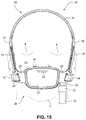
- FIGS. 7-13are front isometric, front, rear, top, bottom, right and left side views, respectively, of a fascia, or front plate, of the patient interface system of FIGS. 1-6 ;
- FIGS. 14-19are front isometric, front, left side, right side, rear and bottom views, respectively, of a patient interface system according to another example embodiment of the present technology
- FIGS. 20-25are front, rear, rear isometric, top, bottom, and left side views, respectively, of a fascia, frame or front plate, of the patient interface system of FIGS. 14-19 ;
- FIG. 26is a front isometric view of a patient interface according to another example embodiment of the present technology and FIGS. 27-33 are front isometric, front, rear, right side, left side, top, and bottom views, respectively, of a fascia, frame or front plate, of the patient interface system of FIG. 26 ;
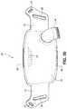
- FIGS. 34-40are front isometric, front, rear, left side, right side, top, and bottom views, respectively, of a patient interface system according to another example embodiment of the present technology
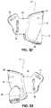
- FIGS. 41-47are front isometric, front, rear, left side, right side, top, and bottom views, respectively, of the fascia, frame or front plate, including an elbow and the patient interface positioning system of the patient interface system of FIGS. 34-40 ;
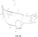
- FIG. 48is a front isometric view of the fascia, or front plate, including the elbow, and the seal (e.g. cushion) of the patient interface system of FIGS. 34-30 ;
- FIGS. 49-55are front isometric, front, rear, right side, left side, top, and bottom views, respectively, of the fascia, frame or front plate, including the elbow, of the patient interface system of FIGS. 34-40 ;
- FIGS. 56-62are front isometric, front, rear, rear isometric, right side, top, and bottom views, respectively, of a patient interface positioning system according to an example embodiment of the present technology
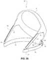
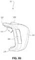
- FIGS. 63-69are front isometric, front, rear, top, bottom, right side, and left side views, respectively, of a mouth seal, or cushion, according to an example embodiment of the present technology
- FIGS. 70-76are front/bottom isometric, front, rear, top, bottom, side, and front/top isometric views, respectively, of a nasal seal, or cushion, according to an example embodiment of the present technology
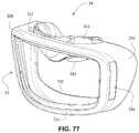
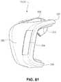
- FIGS. 77-83are front isometric, front, rear isometric, rear, right side, top, and bottom views, respectively, of a seal, or cushion, including the mouth and nasal seals, or cushions, of FIGS. 63-69 and 70-76 , respectively, according to an example embodiment of the present technology;
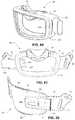
- FIG. 84is a front view of a patient interface system according to another example embodiment of the present technology.
- FIG. 85is a front view of a patient interface system according to another example embodiment of the present technology.
- FIG. 86is a front isometric view of a patient interface system according to another example embodiment of the present technology.
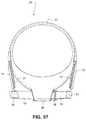
- FIG. 87is a rear view of a patient interface system according to another example embodiment of the present technology.
- FIGS. 88-94are views of a patient interface system according to another example embodiment of the present technology.
- FIG. 95is a front isometric view of a patient interface system according to another example embodiment of the present technology.
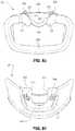
- FIG. 96is a front view of a patient interface system according to another example embodiment of the present technology.
- FIG. 97is a front view of a patient interface system according to another example embodiment of the present technology.
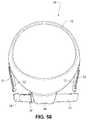
- FIG. 98is a front view of a patient interface system according to another example embodiment of the present technology.
- FIG. 99is a front view of a patient interface system according to another example embodiment of the present technology.
- FIG. 100is a front view of a patient interface system according to another example embodiment of the present technology.
- FIG. 101is a front isometric view of a patient interface system according to another example embodiment of the present technology.
- FIG. 102is an exploded assembly view of a patient interface system according to another example embodiment of the present technology.
- FIG. 103is a front isometric view of a patient interface system according to another example embodiment of the present technology.
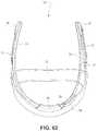
- FIG. 104is a rear view of a mouth seal, or cushion, according to an example embodiment of the present technology.
- FIG. 105is a left side view of the mouth seal, or cushion, of FIG. 104 ;
- FIG. 106is a schematic illustration of a fascia, or front plate, and a seal, or cushion, including an anti-asphyxia valve according to an example embodiment of the present technology
- FIG. 107is a schematic illustration of a fascia, or front plate, and a seal, or cushion, including an anti-asphyxia valve according to another example embodiment of the present technology
- FIG. 108is a schematic illustration of a fascia, or front plate, and a seal, or cushion, including a gusseted side wall according to an example embodiment of the present technology
- FIG. 109is a schematic illustration of a strap, for example a rear strap, of a patient interface positioning system (e.g. headgear) according to an example embodiment of the present technology;
- a patient interface positioning systeme.g. headgear
- FIG. 110is schematic illustration of the strap of FIG. 109 connected to a delivery tube or conduit or hose;
- FIG. 111is a schematic illustration of a strap, for example a rear strap, of a patient interface positioning system (e.g. headgear) according to another example embodiment of the present technology;
- a patient interface positioning systeme.g. headgear
- FIG. 112is a schematic illustration of a strap, for example a rear strap, of a patient interface positioning system (e.g. headgear) according to another example embodiment of the present technology;
- a patient interface positioning systeme.g. headgear
- FIG. 113is a schematic illustration of a fascia, or front plate, including a venting arrangement according to an example embodiment of the present technology
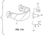
- FIG. 114is a schematic illustration of a patient interface system rotatably connectable to a patient interface positioning system according to an example embodiment of the present technology
- FIG. 115is a rear view of a cushion assembly, including a mouth seal or cushion and a nasal seal or cushion;
- FIG. 116is a front view of the cushion assembly of FIG. 115 including a cushion clip
- FIG. 117is a cross section view of the cushion assembly and cushion clip along line 117 - 117 in FIG. 116 ;
- FIG. 118is a detailed view of the connection of the cushion assembly and the cushion clip at a lower portion of the cushion assembly;
- FIG. 119is a detailed view of FIG. 118 ;
- FIG. 120is a detailed view of the connection of the cushion assembly and the cushion clip at an upper portion of the cushion assembly
- FIG. 121is a detailed view of FIG. 120 ;
- FIG. 122is a top view of the cushion assembly and cushion clip
- FIG. 123is a rear view of the cushion clip
- FIG. 124is a front view of the cushion clip
- FIG. 125is a cross section view of the cushion clip along line 125 - 125 in FIG. 124 ;
- FIG. 126is a left side view of the cushion clip
- FIG. 127is a detailed view of FIG. 125 ;
- FIG. 128is a top view of the cushion clip
- FIG. 129is a rear isometric view of a cushion assembly according to an embodiment of the present technology.
- FIG. 130is a rear view of the cushion assembly of FIG. 129 ;
- FIG. 131is a cross section view of the cushion assembly along line 131 - 131 in FIG. 130 ;
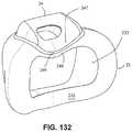
- FIG. 132is a rear isometric view of a cushion according to an embodiment of the present technology.
- FIG. 133is a rear view of the cushion assembly of FIG. 132 ;
- FIG. 134is a cross section view of the cushion assembly along line 134 - 134 in FIG. 133 ;
- FIG. 135is a front isometric view of the cushion assembly and cushion clip of FIG. 125 ;
- FIG. 136is a left side view of the cushion assembly and cushion clip of FIG. 135 .
- airwill be taken to include breathable gases, for example air with supplemental oxygen. It is also acknowledged that the blowers described herein may be designed to pump fluids other than air.
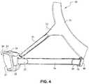
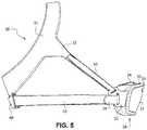
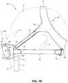
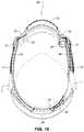
- a patient interface system or mask system 10in accordance with an example embodiment of the present technology comprises a patient interface structure or mask structure 20 that is positioned, stabilized and secured on a patient's head in sealing engagement with the patient's mouth and nasal airways by a patient interface positioning system 30 , e.g. a headgear.
- the patient interface structure 20comprises a fascia or lens or front plate or frame 21 having a mouth seal, or cushion 23 that is connected to the front plate 21 .
- the front plate 21includes patient interface positioning system connectors 22 (e.g. headgear connectors) to connect the patient interface positioning system (e.g. headgear) 30 to the patient interface structure (e.g. mask) 20 .
- the patient interface structurefurther comprises a nasal seal, or cushion 24 connected to the mouth seal, or cushion 23 to seal the patient's nasal airways.
- a vent 25may be provided in the front plate 21 to vent exhaled gases in a breathing chamber defined by the front plate 21 , the mouth cushion 23 and the nasal cushion 24 .
- the ventsmay be provided in the front plate 21 proximate the nares and/or mouth of the patient to improve CO.sub.2 washout.
- the array of vent holes 25may be laser cut, molded or otherwise formed in an upper region of front plate 21 .
- the patient interface positioning system 30comprises a crown strap 31 adapted to cup or encircle the crown of the patient's head.
- Top, or upper side straps 32extend from the crown strap 31 and connect to the front plate 21 through slots 27 .
- the ends 33 of the top side straps 32may be looped through the slots 27 and connect to the top side straps 32 by, for example, hook and loop material. It should also be appreciated that other connections, for example buckles, may be used to secure the ends 33 of the top side straps 32 .
- the top side straps 32may be thickened or widened at the region where they connect to the crown strap 31 to allow ends 33 a larger space to connect to and also a range of angles to position ends 33 relative to slots 27 , thereby improving the fit range of the headgear 30 . Such an arrangement may also improve comfort and/or to assist in stabilizing and positioning the top side straps 32 on the patient's cheek bone regions.
- the crown strap 31may further comprise a loop 40 through which a right bottom, or lower side strap 35 may pass and connect to a left bottom, or lower side strap 34 .
- the loopmay be formed in the lower strap(s) 34 and/or 35 , for example as shown in U.S. Applications 61/443,623 and 61/457,981, each of which is incorporated by reference herein in its entirety.
- other headgearmay be used with the patient interface system, for example as disclosed in U.S. Patent Application Publication 2008/0110466 A1, the entire contents of which are incorporated herein by reference.
- the bottom right side strap 35may comprise a first end 38 in the form of a loop or slot and a first end 36 of the bottom left side strap 34 may connect to the first end 38 by passing through the loop or slot and connecting through hook and loop material or buckles or other connectors.
- the second end 37 of the bottom left side strap 34 and the second end 39 of the bottom right side strap 35may be connected to the front plate 21 through slots 26 in the connectors 22 .
- Headgear 30may be formed from a composite e.g. fabric and foam, which may be flame laminated and may be ultrasonically die cut or welded along its edge to create a rounded, more comfortable edge.
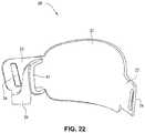
- the front plate 21is configured to conform to or accommodate the shape of the patient's face.
- the front plate 21may be flexible to allow the front plate to follow the shape of the patient's face.
- the front plate 21may be formed of, for example, a flexible polymer that is able to bend and conform around the patient's mouth once the front plate 21 is connected to the patient interface positioning system 30 and fitted to the patient.
- the front plate 21may also be malleable to allow the front plate to conform to the shape of the patient's face.
- a rib(s) 28may be provided to the front plate 21 .
- the ribs 28may be provided along the top and bottom of the front plate 21 and aid in alignment and engagement with the cushion 23 , as well as providing strength to the fascia.
- Front plate 21may be substantially planar, curved and/or smooth.
- Masks known in the arttend to include complex shapes and/or structures on the frame, and these complex shapes and/or structures make it difficult to see the patient's mouth clearly and to clean the frame.
- these complex shapes and/or structuresmay include elbows, elbow connectors, ports, ridges, contours, headgear connectors, etc.
- Front plate 21is adapted to be substantially smooth and without complex shapes or structures i.e. having a substantially planar surface in the region of the patient's mouth, to act as a window to permit clear visibility to the patient's mouth.
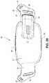
- the patient interface structure 20may be generally rectangularly or trapezoidally shaped and comprise the front panel 21 that wraps across the face of the patient 1 , and the cushion 23 , 24 attached to the front plate 21 .
- the cushion 23may comprise the integrated mouth seal or cushion 23 and the nasal seal or cushion 24 .
- the front plate 21may be generally convex when viewed from the non-patient contacting side, curved or rounded shaped and adapted to follow the contour of the patient's face.
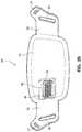
- the bottom side strap connector slots 26 and the top side strap connector slots 27 of the connectors 22 on either side of the front plate 21may receive the headgear straps 32 , 34 , 35 and the tension or force from the headgear straps 32 , 34 , 35 may bend or flex the front plate 21 to conform to the shape of the patient's face.
- the top side strap connector slots 27are directed generally upwards and are adapted to aid sealing of the nasal cushion 24 and direct the headgear away from the patient's eyes 4
- the bottom side strap connector slots 26are adapted to aid sealing of the mouth cushion 23 and direct the headgear straps 34 , 35 under the ears 2 of the patient 1 .
- the fascia or lens or front plate 21is positioned in front of the patient's mouth, and is adapted to provide support to the other components of the patient interface system 10 and aid in positioning these other components, for example the front plate has headgear connectors 22 and a cushion connection portion adapted to receive the patient interface positioning system 30 and a cushion 23 and position these components relative to one another.
- the front plate 21also provides some structure to the patient interface system 10 due to the comparatively greater rigidity of the front plate 21 when compared to the cushion 23 .
- the front plate 21may take the form of a lens made from a clear material such as nylon, polycarbonate or nearly clear material such as polypropylene.
- the lensmay be shaded, selectively shaded (e.g. gradient, patterned, random assortment of shapes), printed on or otherwise coloured.
- the lensmay also have colour changing properties e.g. it may be clear when the light is on, and may be opaque when the light it off.
- the lensmay also be customizable.
- the lensmay be provided with a skin or adhesive layer that may customize or otherwise alter the lens.
- the lensmay be surface treated e.g. frosted.
- the lensmay be die cut, drape formed, vacuum formed, molded, cast, ultrasonically cut or formed in any other method to create the desired shape.
- the lensmay also be formed with vent holes.
- the vent holesmay be molded in, laser cut or otherwise formed with the lens.
- the lensmay be flexible or capable of being shaped to fit the patient's face.
- the cushion or seal of the patient interface systemmay comprise two components the mouth cushion or seal 23 and the nasal cushion or seal 24 .
- the cushions 23 , 24may be molded together or otherwise permanently attached (e.g. glue, weld).
- the mouth cushion 23provides the mouth sealing portion and also the support for the nasal cushion 24 .
- the mouth cushion 23also connects to the front plate 21 .
- the nasal cushion 24is a nares sealing portion that may be molded from the same or alternative material to mouth cushion 23 . Separating the cushion into two components allows use of a lower durometer (i.e. lower hardness) material for the nasal seal or cushion 24 , and the tooling required to mold the nasal seal or cushion 24 with the mouth seal or cushion 24 is difficult, so molding them in two steps rather than one facilitates manufacturing.
- the cushions 23 , 24may be made from a single material such as silicone, TPE, TPU. However, combinations of materials and/or hardnesses of materials may be used.
- the mouth seal or cushion 23may have a TPE or silicone body, with a seal portion or flap adapted to interface with the patient.
- the nasal seal 24may comprise a seal portion formed of an alternative material, for example a lower hardness silicone, TPU, fabric, etc.
- the mouth cushion 23comprises a groove or channel 231 around a front portion 238 that is adapted to receive the front plate 21 .
- the channel 231may have a flap (or sealing wall) 232 around the inner side of the channel that is adapted to seal against the face of the patient around the patient's mouth.
- the flap 232may comprise a single wall seal, although it should be appreciated that the flap 232 may comprise more than one wall, for example two or three walls.
- the mouth cushion 23may be constructed from a deformable material such as TPE, TPU, silicone, foam (skinned or unskinned), or gel.
- the mouth cushion 23may be insert, over, or co-moulded to the front plate 21 .
- a cushion clipmay be provided to the cushion to clip to the front plate 21 .
- the clipmay be insert, over, or co-moulded into the cushion 23 as one part.
- the cushion clipmay add stiffness and rigidity to the cushion 23 where required, provide patient interaction points, and allow for a locating and attaching method of the cushion 23 to the front plate 21 , e.g. the cushion clip may snap onto the front plate 21 .
- the cushion clipmay simplify the process of attaching the cushion 23 to the front plate 21 by reducing stretching and warping of the cushion 23 during assembly.
- Slots 234are provided in side walls 233 of the cushion 23 and are adapted to receive the connectors 22 of the front plate 21 . Slots 234 may be generally rectangular, however any other shape may be possible, such that slots 234 may be complimentary to the shape of connectors 22 . Connectors 22 may sealingly engage with side walls 233 , for example side walls 233 may comprise a lip seal or other arrangement adapted to seal against connectors 22 .
- the upper portion 237 of the mouth seal or cushion 23has a greater depth when compared with the lower portion 239 of the mouth seal or cushion 23 , i.e. the distance of the seal portion to the clip portion of the upper portion may be longer than the distance from the seal portion to the clip portion of the lower portion, to tilt the cushion 23 when in use to reduce the profile of the mask 20 when in use.
- the upper portion 237 of the mouth seal or cushion 23may also have a greater depth than the lower portion 239 to accommodate nasal seal or cushion 24 and patients with long noses.
- Flaps 252are provided on nares support portions 235 to assist in positioning and stabilizing the nasal seal or cushion 24 to engage with the sides of the patient's nose or the patient's top lip. Raised portions 253 on the nares support portion 235 aid in positioning the nasal seal 24 against the flares of the patient's nostrils. Indents or apertures 254 are formed in the nasal support portions 235 and are adapted to receive lugs 241 on nasal seal or cushion 24 to aid in alignment.
- a channel 251may be provided around the nares support portions 235 to form a flexible region (e.g. could be localized thinning of material) adapted to permit movement of the nasal seal or cushion 24 to accommodate varying anthropometrics.
- the side walls 233 of the mouth seal or cushion 23may have a “question mark” cross section, i.e. the mouth seal portion does not have a straight wall section but rather has a gusseted side wall that acts as a built-in spring so that the mouth seal portion can flex to fit varying patient anthropometrics.
- a side wall cross sectionis disclosed in, for example, U.S. Patent Application Publication 2008/0110464 A1, the entire contents of which are incorporated herein by reference.
- the front portion 238 , the side walls 233 and the flap 232 of the mouth cushion 23may have different hardnesses.
- the front portion 238may have a Shore A durometer of about 30-50, for example about 40.
- the side walls 233 and/or the flap 232may have a Shore A durometer of 5-10, for example about 7.
- the cushion or sealmay be formed of a foam, gel, or low durometer material to seal with the patient.
- Two gusset or spring portions 288 , 289may be formed behind the seal portion to aid in adjustment of the positioned of the seal portion.
- the corner 287 of the nose regionmay be raised to ensure the seal abuts the patient's face and seals in this region.
- a gusset type arrangementmay be provided to permit flexibility of the cushion and aid sealing under air pressure, with the flap 232 turning outwards. This arrangement may increase the fit range.
- the nasal seal or cushion 24may comprise lugs 241 adapted to be received in indents 254 of the nare support portions 235 of the mouth seal or cushion 23 .
- the nasal seal or cushion 24may have a geometry the same as or similar to that disclosed in, for example, WO 2010/139014 A1, the entire contents of which are incorporated herein by reference.
- the nare support portions 235 and the cradle wall 236form a trampoline type join with the nasal seal or cushion 24 .
- the nasal seal or cushion 24may have a Shore A durometer of about 30-50, for example about 40.
- the nasal seal or cushion 24may have a Shore A durometer of about 5-10, for example about 7.
- the flaps 252 of the nares support portions 235 of the mouth seal or cushion 23attach to the respective sides of the nasal seal or cushion 24 .
- a central portion 242 of the nasal seal or cushion 24is left unsupported by the nares support portions 235 to allow the flexibility of the central portion 242 accommodate varying shaped lip regions of patients.
- the upper portion 237 of the mouth seal or cushion 23is generally in line with or vertically aligned to the nasal seal or cushion 24 so the patient's nose is likely to rest inside the cushion.
- the nasal seal or cushion 24is positioned to reside within the mouth cushion 23 which reduces visual bulk and streamlines the outer edge of the mask. As shown in FIG.
- the slots 234 for the connectors 22 of the front plate 21are positioned below the nasal seal 24 so as to direct the headgear straps 34 , 35 along or below the patient's cheeks.
- the patient interface systemmay comprise a number of nasal seals or cushions 24 .
- a single mouth cushion 23may be provided to fit a large percentage of the patient population and two or more nasal seals or cushions 24 may be provided to provide a more custom fit for individual patients nose sizes.
- a nasal seal or cushioncomprising nasal pillows may be provided to the mouth cushion. It should be appreciated that a plurality of nasal seals or cushions having different size nasal pillows may be provided to the patient interface system.
- the tube connectormay comprise an elbow 269 that is rotatably connected to the front plate 21 .
- Elbow 269may be lockable in the two positions as show, i.e. left and right horizontal orientations.
- the patient interface structure 20may include an anti-asphyxia valve 360 provided in the front plate 21 .
- the front plate 21may include a receptacle 270 configured to receive a clip 271 provided on a strap 35 of the patient interface positioning system. As shown in FIG. 100 , the front plate 21 may include receptacles 270 on opposing sides, each configured to receive a clip 271 attached to a strap 34 , 35 . The clips and receptacles may also be magnetic.
- a seal or cushion assemblyincludes a mouth seal or cushion 23 and a nasal seal or cushion 24 .
- the cushion assemblymay be similar to that disclosed with respect to FIGS. 63-83 except as otherwise described herein.
- the cushion assemblymay comprise a cushion clip 400 attached to the cushion assembly and configured to attach the cushion assembly to a fascia or front plate or lens as described herein.
- the cushion clip 400may comprise detents 402 on opposite sides to retain the cushion assembly on the fascia. As shown in, for example, FIG. 128 , the cushion clip 400 may have a curved portion 401 that curves away from the cushion assembly to allow the nasal seal 24 to have a greater depth than a top surface of the mouth cushion 23 .
- nasal seal 24may accommodate long noses.
- the central portion 242 of the mouth cushion 23may dip or curve downwards towards the patient's lip to avoid contacting the patient's septum.
- nasal seal 24may comprise raised upper corner regions, these raised upper corner regions adapted to engage a patient's nostrils or nasal flares, thereby reducing the force on the patient's nose tip.
- the height of the aperture in the mouth cushionmay be about 25-35 mm.
- the height of the aperture on the mouth cushionmay be about 25-30 mm.
- the heightis measured from the lowest portion of the opening at the chin region to the dip or curve of the opening at the top lip region.
- the height of the aperturemay increase towards the cheek or left and ride side regions.
- the height of the aperture in the nose cushionmay be about 5-15 mm.
- the height of the aperture in the nose cushionmay be about 7-12 mm.
- the height of the aperture in the nose cushionmay be less in the central region of the aperture compared to the height of the aperture at the side regions. That is, the nose cushion aperture may have a dip or curved portion at the central region. Such an arrangement may aid in alignment of the cushion, avoid placing excess pressure on the patient's septum and/or ensure that the lower portion of the nasal cushion is not under tension and therefore may not exert pressure on the patient's top lip.
- the width of the aperture in the mouth cushionmay be about 60-70 mm.
- the width of the aperture in the mouth cushionmay be about 63-68 mm. Such a width may accommodate varying mouth widths of patient's.
- the total width of the nose and mouth cushionmay be about 90-105 mm.
- the total width of the nose and mouth cushionmay be about 95-100 mm.
- Such a widthmay accommodate varying patient anthropometrics.
- the total height of the nose and mouth cushionmay be about 60-75 mm.
- the total height of the nose and mouth cushionmay be about 65-75 mm.
- Such a heightmay accommodate varying patient anthropometrics.
- the patient contacting portion of the nose and/or mouth cushionsmay be about 0.3-1.5 mm thick.
- patient contacting portion of the nose and/or mouth cushionsmay be about 0.3-0.7 mm thick. Such a thickness may ensure conformability of the cushion and comfort for the patient.
- the height of the clipmay be about 40-55 mm. Preferably, the height of the clip may be about 45-55 mm.
- the height of the clipmay be greater than the height of the mouth cushion aperture. Such an arrangement may be simpler to engage the clip with a fascia (for example) and may increase the structural integrity of the cushion.
- the width of the clipmay be about 70-85 mm.
- the width of the clipmay be about 75-80 mm.
- the width of the clipmay be greater than the width of the mouth cushion aperture. Such an arrangement may be simpler to engage the clip with a fascia (for example) and may increase the structural integrity of the cushion.
- the cushion clipmay be generally trapezoidal, with the top portion being wider than the lower portion.
- Such an arrangementmay mean that the overall shape of the mask is shaped to match the general shape of a humans face i.e. taper from a greater width at the top lip region to a lower width at the chin region.
- the top portionmay be, for example, about 75-85 mm wide.
- the lower portionmay be, for example, about 65-75 mm wide.
- the cushionmay be integrally formed in one piece.
- the mouth cushion 23may have a single sealing wall 232 and the nasal cushion 24 may have a dual wall construction comprising a sealing wall 243 and a supporting wall 244 .
- the mouth cushion 23 and the nasal cushion 24may each include a single wall, or each may include multiple walls.
- the sealing walls 232 and 243 of the mouth cushion 23 and the nasal cushion 24may curve inwards toward a breathing chamber or cavity formed by the cushions.
- only a portion of the supporting wall 244 of the nasal cushion 24may be present, for example, at the tip of the nose region and not at the top of the lip region.
- a parting line 245 of the mould used to form the cushion assemblymay be provided so as to be above the patient contacting areas of the cushion assembly.
- the cushion assembly and the cushion clip 400may be formed integrally in one piece.
- the cushion assemblymay be insert, over, or co-moulded into the cushion 23 as one part.
- the cushion assembly and the cushion clip 400may be chemically or mechanically bonded together.
- the cushion assembly and cushion clip 400may also be repeatably attachable and detachable from one another.
- the cushion clip 400may include a flange configured to be received in a channel in the cushion assembly.
- the cushion clip 400may include a flange or rib 403 to increase the surface area of the cushion clip 400 to enhance the bond between the cushion clip 400 and the cushion assembly.
- the cushion assemblyfor example the mouth cushion 23 , may include a thickened region 310 to provide support for the sealing wall 232 and to improve the bond to the cushion clip 400 .
- Rib 403may have a varying height around the perimeter of the cushion clip 400 . This varying height may support the cushion more in some regions (i.e. the regions with a greater rib height such as sensitive regions of the face such as the top lip) compared to support in other regions (i.e. regions with a lower rib height such as less sensitive regions of the face such as the cheeks).
- a cushion assembly including a mouth cushion 23 and a nasal cushion 24may comprise a continuous sealing surface 246 .
- the sealing surface 246is continuous with the mouth cushion sealing wall 232 and the nasal cushion sealing wall 243 .
- the curvature of the sealing surface 246may be constant or approximately constant. Such an arrangement may be comfortable for the patient as there are no ridges or undulations that may mark or otherwise irritate the patient's skin. In this arrangement, the definition between the nose and mouth seal portions is not distinct, such that the seal is continuous.
- a cushion assembly including a mouth cushion 23 and a nasal cushion 24includes separate sealing surfaces 247 , 248 .
- a channel 249is provided to separate the nasal sealing surface 247 from the mouth sealing surface 248 .
- Such an arrangementmay be preferable as the nose and mouth seal portions are visually distinct which may assist the patient with aligning the device.
- a patient interface system 10includes a delivery hose, or tube, or conduit 11 that is connected to the front panel 21 by a connector 12 , e.g. a swivel connector.
- the tube 11may be as disclosed in, for example, U.S. Patent Application Publication 2009/0078259 A1, the entire contents of which are incorporated herein by reference.
- the front panelincludes an air inlet or elbow 29 that may be integrally formed with the front plate 21 . It should be appreciated that the elbow 29 may be formed separately from the front plate 21 and attached or connected to the front plate 21 or the cushion 23 , for example by adhesive or mechanical fasteners.
- the elbow 29is positioned behind or adjacent to the connector 22 of the front plate 21 on the left side, although it should be appreciated that the elbow 29 may be provided on the right side of the front plate 21 .
- the shape of the elbow 29is curved to avoid obscuring the headgear connector 22 . However other configurations would be possible if the headgear connector 22 was located in an alternative position.
- the tube connection portion of the elbow 29is adapted to receive the tube 11 in a longitudinal (e.g. vertical) direction, however other orientations are possible.
- the elbow 29is not visible from the front as it is hidden behind the headgear connector 22 of the front plate 21 . This arrangement is advantageous as it is reduces the part count (i.e. no separate elbow is required) and the design may be more visually appealing.
- the tube 11is connected at the side of the patient interface or mask system 10 so as to permit clear view to the patient's mouth. Because the tube connection is positioned behind the headgear connector 22 at the front plate 21 , the tube 11 is less obtrusive.
- the eyes 4 of the patient 1are unobstructed and in the case of the front plate 21 being in the form of a lens, for example a clear polymer (e.g. polycarbonate), the patient's mouth would also be visible.
- the elbow 29may comprise a lip or protruding edge 41 , in the form of for example a chamfer, adapted to receive a slot or aperture of the cushion.
- the cushion 23may comprise a slot that may be positioned to abut or align with the chamfer to aid alignment, and also ensure an air tight seal between the cushion 23 and the front plate 21 is achieved.
- the patient interface structure 20sits under the patient's nose 3 and the nasal cushion 24 seals around or in the nares.
- the mouth cushion 23sits in the crease of the patient's chin 5 .
- the crown strap 31 of the headgear 30is positioned over the top of the patient's crown and generally in line with the patient's ears 2 , although it should be appreciated that the positioning of the crown strap 31 may vary between patients.
- front plate 21 shown in FIGS. 20-25includes only the bottom side strap connector slots 26 , it should be appreciated that the embodiment shown in FIGS. 20-25 may also comprise top sides strap connector slots 27 . It should also be appreciated that the front plate 21 may be provided with a vent, or alternatively another component, such as the tube 11 , the connector 12 , or the elbow 29 may have a vent.
- a tube connector 272may be positioned either on the front plate 21 or molded with the cushion 23 .
- the tube connector 272may receive an intermediate portion or portion 274 of a tube 273 that may interface with the tube connector 272 by an interference fit.
- the interference fitmay be achieved by pinching or otherwise misshaping the intermediate portion or portion 274 of the tube 273 and placing it within the tube connector 272 .
- the intermediate portion or portion 274 of the tube 273may resiliently flex back to its original shape and interface with an inner surface of the tube connector 272 .
- tube 273 that may interface with the tube connector 272 by an interference fitsuch as an isometric taper or a quarter turn lock.
- a patient interface system 10comprises a patient interface structure 20 comprising a front plate 21 , a mouth cushion 23 provided to the front plate 21 , and a nasal cushion 24 provided to the mouth cushion 23 .
- the front plate 21comprises a tube connector 42 on a front surface that is configured to receive a tube in a horizontal direction.
- a tubemay connect directly to the tube connector 42 or may have an intermediate structure such as an elbow or swivel between the tube and the tube connector 42 , possibly shaped to avoid the tube obscuring the headgear connector 22 .
- the tube connector 42may have vent holes 25 molded or otherwise formed in it.
- the tube connector 42may also have a lip or protruding edge 43 , which may aid in sealing the tube connector 42 to the tube or intermediate structure.
- the tube connector 42may have an anti-asphyxia valve (AAV) in form of a flap built in (described in more detail below) that may occlude or block some of the vent holes 25 when air is delivered from the tube and through the tube connector 42 . When air pressure is not supplied, the AAV may flip away from the vent holes to permit the patient to breath in sufficient atmospheric air.
- AAVanti-asphyxia valve
- the rear face of the front plate 21may have an aperture 44 adapted to permit the flow of air from the tube connector into the mask.
- the vents 25may have a thicker cross section than the rest of the tube connector 42 (e.g. they are on a raised rectangular portion) to improve manufacturability. This may also be to increase the length of the vent holes 25 as longer vent holes are typically quieter than comparatively shorter vent holes.
- the tube connector 42may follow the same general curvature of the front plate to reduce the visual bulk (i.e. more streamlined look) of the mask and aid in tube management.
- a patient interface system 10may comprise an elbow 45 connected substantially perpendicular to the front plate 21 .
- the elbow 45may be a swivel elbow or may be a ball joint elbow.
- the elbow 45may be removably attachable or molded with the front plate 21 .
- a patient interface system 10may comprise a front plate 21 having a vent 25 comprising a plurality of vent holes provided around a perimeter of the front plate 21 .
- the perimeter arrangementaids diffusivity of the exhaust gases and reduces the visibility of the vent 25 .
- a patient interface system 10may comprise a front plate 21 having a vent 25 that comprises micro-perforated holes over the front surface of the front plate 21 .
- a tortuous vent path through front plate 21may be provided for reducing noise.
- the tortuous pathwill slow down the exhaled gases 296 as it moves through the tortuous path, thereby having a lower sound power.
- the mouth sealmay have an interface seal 293 and a flap or castellation 294 that obstructs the vent holes 25 , with the exhaled gases 296 moving through the vented pathway 295 of a raised portion 292 of the front plate 21 rather than directly out of the vent holes 25 to increase the length of the path for exhaled gases to get out of the mask.
- a patient interface system 10may include a mouth cushion 23 having a tube cuff 255 attached to, for example, the side wall 233 of the cushion 23 .
- the tube cuff 255may be moulded onto the side wall 233 and may have a hardness greater than that of the side wall 233 .
- a tube cuff 268may be moulded onto the cushion 23 that is configured to be connected to a connector 12 , e.g. a swivel connector, that is configured to be connected to a tube 11 , for example a tube as disclosed in U.S. Patent Application Publication 2009/0078259 A1, the entire contents of which are incorporated herein by reference. It should be appreciated that the tube cuff 268 may be connected to the cushion by, for example, adhesive or mechanical connectors.
- a gap 286 between a tube connector 283 and a cuff 284may be adapted to receive a headgear strap that extends in a substantially vertical direction.
- the cuff 284may include a link or slot 285 to receive a headgear strap that extends in a substantially horizontal direction.
- the cuff 284may be soft or relatively flexible.
- the cuff 284may be glued on or otherwise attached to the tube connector 283 .
- the cuff 284may be formed with the tube connector 283 .
- a patient interface system 10may comprise a front plate or lens 21 having a hole 256 .
- An anti-asphyxia valve in the form of a flap 257 formed in the mouth seal or cushion 23is forced against the front plate 21 and covers the hole 256 when a flow of pressurized gas is delivered through a tube or hose or conduit 258 .
- the flap 257is released from contact with the front plate 21 and uncovers the hole 256 , allowing the patient to breathe ambient air through the hole 256 in the front plate 21 .
- a patient interface system 10may comprise a front plate 21 having a tube connector 42 configured for connection with a tube or hose or conduit 259 .
- the tube connector 42comprises an aperture or window 264 that may be closed by an anti-asphyxia valve 260 .
- the anti-asphyxia valve 260comprises a flap 261 that is configured to open and close the aperture 264 .
- the flap 261may comprise a vent 25 for venting exhalation gases when the flap 261 closes the aperture 264 .
- the anti-asphyxia valvefurther includes a tab 262 that secures the anti-asphyxia valve 260 in the tube connector 42 through a slot 265 in the tube connector 42 .
- the flap 261is pivotably connected to the tab 262 by a hinge 263 , e.g. a living hinge. As shown in FIG. 94 , in the absence of a flow of gas in the tube connector 42 , the flap 261 extends across the tube connector, and the patient may breathe through the aperture 264 . When gas flow 266 is delivered to the tube connector 42 , the pressure of the gas flow 266 pivots the flap 261 in the direction shown by arrow 267 to close the aperture 264 . Exhalation gases may be vented through the vent 25 . Referring to FIG. 92 , the flap 261 may include elongated vent holes 25 to reduce venting noise and increase diffusivity of the vent flow.
- a hinge 263e.g. a living hinge.
- the cushionmay have a flap or thin portion 290 around its perimeter that interfaces or otherwise abuts the front plate 21 .
- the flap 290may be pressure activated i.e. when air is delivered under pressure into the mask, the flap 290 may be forced to abut the front plate 21 causing an air tight seal. If air is no longer delivered to the mask, the flap 290 may relax and permit air from atmosphere into the mask via a gap 291 created between the flap 290 and the front plate 21 .
- a patient interface system 10may comprise a polyester front plate or window 279 having a TPE “macro” seal 280 and a low durometer nasal seal 281 comprising pillows, or a seal as disclosed in WO 2010/139014 A1, the entire contents of which are incorporated herein by reference.
- a foam “micro” seal 275may be attached to the seal 280 .
- a TPE or TPU headgear 276may be provided to position the patient interface system on the patient's head.
- Elastic webbing or ultrasonic die cut spacer fabric 277may be provided.
- a tube connect 278may be connected to a textile sock 282 .
- a headgear strape.g. a lower headgear strap that is positioned under the patient's ears and loops through a slot in the crown strap, may be connected to an air delivery tube 298 .
- the air delivery tube 298may connect to an end of the headgear strap 297 , with gases being delivered through the headgear clip 299 .
- the clips 299 , 300may interface with the front plate.
- the headgear strap 301may be configured to deliver gases through an air delivery tube 302 and the clips 303 , 304 may be formed in such a way that the strap 301 can be oriented either left ( FIG. 111 ) to right or right to left ( FIG. 112 ).
- the front plate 21may include a plurality of attachment locations 305 for the patient interface positioning system, e.g. headgear, and/or a rotatable attachment location 306 that provides adjustment of the angle between the patient interface structure, e.g. mask, and the patient interface positioning system, e.g. headgear.
- the attachment locationsmay be in the form of rings 307 .
- the fascia, frame or lens portionmay comprise a fixed elbow connection, the elbow connection directed horizontally. Such an arrangement can be seen in, for example, FIG. 99 .
- the fasciabe structured and arranged to be flipped or rotated, such that the direction of the elbow may be changed from pointing to the left, for example, to pointing to the right. This means that the fascia may be symmetrical.
Landscapes
- Health & Medical Sciences (AREA)
- Pulmonology (AREA)
- Life Sciences & Earth Sciences (AREA)
- Animal Behavior & Ethology (AREA)
- Anesthesiology (AREA)
- Biomedical Technology (AREA)
- Heart & Thoracic Surgery (AREA)
- Hematology (AREA)
- Emergency Medicine (AREA)
- Engineering & Computer Science (AREA)
- General Health & Medical Sciences (AREA)
- Public Health (AREA)
- Veterinary Medicine (AREA)
- Otolaryngology (AREA)
- Orthopedics, Nursing, And Contraception (AREA)
- Respiratory Apparatuses And Protective Means (AREA)
- Percussion Or Vibration Massage (AREA)
Abstract
Description
Claims (22)
Priority Applications (14)
| Application Number | Priority Date | Filing Date | Title |
|---|---|---|---|
| US16/032,722US11045619B2 (en) | 2010-09-30 | 2018-07-11 | Patient interface systems |
| US16/198,492US10456545B2 (en) | 2010-09-30 | 2018-11-21 | Patient interface systems |
| US16/204,912US10449317B2 (en) | 2010-09-30 | 2018-11-29 | Patient interface systems |
| US16/205,714US10537696B2 (en) | 2010-09-30 | 2018-11-30 | Patient interface systems |
| US16/994,904US11040164B2 (en) | 2010-09-30 | 2020-08-17 | Patient interface systems |
| US16/997,189US11213649B2 (en) | 2010-09-30 | 2020-08-19 | Patient interface systems |
| US17/076,368US11344691B2 (en) | 2010-09-30 | 2020-10-21 | Patient interface systems |
| US17/330,490US12390611B2 (en) | 2010-09-30 | 2021-05-26 | Patient interface systems |
| US17/509,221US11464931B2 (en) | 2010-09-30 | 2021-10-25 | Patient interface systems |
| US17/933,504US11638799B2 (en) | 2010-09-30 | 2022-09-20 | Patient interface systems |
| US18/188,905US11931514B2 (en) | 2010-09-30 | 2023-03-23 | Patient interface systems |
| US18/823,118US20240424239A1 (en) | 2010-09-30 | 2024-09-03 | Patient interface systems |
| US19/017,902US20250144348A1 (en) | 2010-09-30 | 2025-01-13 | Patient interface systems |
| US19/017,885US20250144347A1 (en) | 2010-09-30 | 2025-01-13 | Patient interface systems |
Applications Claiming Priority (8)
| Application Number | Priority Date | Filing Date | Title |
|---|---|---|---|
| US38835710P | 2010-09-30 | 2010-09-30 | |
| US201161443623P | 2011-02-16 | 2011-02-16 | |
| US201161457981P | 2011-07-27 | 2011-07-27 | |
| US201161528524P | 2011-08-29 | 2011-08-29 | |
| PCT/AU2011/001258WO2012040791A1 (en) | 2010-09-30 | 2011-09-30 | Patient interface systems |
| US201313876624A | 2013-03-28 | 2013-03-28 | |
| US14/645,457US10052448B2 (en) | 2010-09-30 | 2015-03-12 | Patient interface systems |
| US16/032,722US11045619B2 (en) | 2010-09-30 | 2018-07-11 | Patient interface systems |
Related Parent Applications (1)
| Application Number | Title | Priority Date | Filing Date |
|---|---|---|---|
| US14/645,457ContinuationUS10052448B2 (en) | 2010-09-30 | 2015-03-12 | Patient interface systems |
Related Child Applications (3)
| Application Number | Title | Priority Date | Filing Date |
|---|---|---|---|
| US16/198,492ContinuationUS10456545B2 (en) | 2010-09-30 | 2018-11-21 | Patient interface systems |
| US16/994,904ContinuationUS11040164B2 (en) | 2010-09-30 | 2020-08-17 | Patient interface systems |
| US17/330,490ContinuationUS12390611B2 (en) | 2010-09-30 | 2021-05-26 | Patient interface systems |
Publications (2)
| Publication Number | Publication Date |
|---|---|
| US20180318540A1 US20180318540A1 (en) | 2018-11-08 |
| US11045619B2true US11045619B2 (en) | 2021-06-29 |
Family
ID=76599570
Family Applications (16)
| Application Number | Title | Priority Date | Filing Date |
|---|---|---|---|
| US13/876,624ActiveUS9010330B2 (en) | 2010-09-30 | 2011-09-30 | Patient interface systems |
| US14/645,457Active2033-04-15US10052448B2 (en) | 2010-09-30 | 2015-03-12 | Patient interface systems |
| US16/032,722Active2032-10-26US11045619B2 (en) | 2010-09-30 | 2018-07-11 | Patient interface systems |
| US16/198,492ActiveUS10456545B2 (en) | 2010-09-30 | 2018-11-21 | Patient interface systems |
| US16/204,912ActiveUS10449317B2 (en) | 2010-09-30 | 2018-11-29 | Patient interface systems |
| US16/205,714ActiveUS10537696B2 (en) | 2010-09-30 | 2018-11-30 | Patient interface systems |
| US16/994,904ActiveUS11040164B2 (en) | 2010-09-30 | 2020-08-17 | Patient interface systems |
| US16/997,189ActiveUS11213649B2 (en) | 2010-09-30 | 2020-08-19 | Patient interface systems |
| US17/076,368ActiveUS11344691B2 (en) | 2010-09-30 | 2020-10-21 | Patient interface systems |
| US17/330,490Active2034-08-30US12390611B2 (en) | 2010-09-30 | 2021-05-26 | Patient interface systems |
| US17/509,221ActiveUS11464931B2 (en) | 2010-09-30 | 2021-10-25 | Patient interface systems |
| US17/933,504ActiveUS11638799B2 (en) | 2010-09-30 | 2022-09-20 | Patient interface systems |
| US18/188,905ActiveUS11931514B2 (en) | 2010-09-30 | 2023-03-23 | Patient interface systems |
| US18/823,118PendingUS20240424239A1 (en) | 2010-09-30 | 2024-09-03 | Patient interface systems |
| US19/017,885PendingUS20250144347A1 (en) | 2010-09-30 | 2025-01-13 | Patient interface systems |
| US19/017,902PendingUS20250144348A1 (en) | 2010-09-30 | 2025-01-13 | Patient interface systems |
Family Applications Before (2)
| Application Number | Title | Priority Date | Filing Date |
|---|---|---|---|
| US13/876,624ActiveUS9010330B2 (en) | 2010-09-30 | 2011-09-30 | Patient interface systems |
| US14/645,457Active2033-04-15US10052448B2 (en) | 2010-09-30 | 2015-03-12 | Patient interface systems |
Family Applications After (13)
| Application Number | Title | Priority Date | Filing Date |
|---|---|---|---|
| US16/198,492ActiveUS10456545B2 (en) | 2010-09-30 | 2018-11-21 | Patient interface systems |
| US16/204,912ActiveUS10449317B2 (en) | 2010-09-30 | 2018-11-29 | Patient interface systems |
| US16/205,714ActiveUS10537696B2 (en) | 2010-09-30 | 2018-11-30 | Patient interface systems |
| US16/994,904ActiveUS11040164B2 (en) | 2010-09-30 | 2020-08-17 | Patient interface systems |
| US16/997,189ActiveUS11213649B2 (en) | 2010-09-30 | 2020-08-19 | Patient interface systems |
| US17/076,368ActiveUS11344691B2 (en) | 2010-09-30 | 2020-10-21 | Patient interface systems |
| US17/330,490Active2034-08-30US12390611B2 (en) | 2010-09-30 | 2021-05-26 | Patient interface systems |
| US17/509,221ActiveUS11464931B2 (en) | 2010-09-30 | 2021-10-25 | Patient interface systems |
| US17/933,504ActiveUS11638799B2 (en) | 2010-09-30 | 2022-09-20 | Patient interface systems |
| US18/188,905ActiveUS11931514B2 (en) | 2010-09-30 | 2023-03-23 | Patient interface systems |
| US18/823,118PendingUS20240424239A1 (en) | 2010-09-30 | 2024-09-03 | Patient interface systems |
| US19/017,885PendingUS20250144347A1 (en) | 2010-09-30 | 2025-01-13 | Patient interface systems |
| US19/017,902PendingUS20250144348A1 (en) | 2010-09-30 | 2025-01-13 | Patient interface systems |
Country Status (7)
| Country | Link |
|---|---|
| US (16) | US9010330B2 (en) |
| EP (4) | EP2621572B1 (en) |
| JP (1) | JP6096662B2 (en) |
| CN (1) | CN103153379B (en) |
| AU (1) | AU2011308094B2 (en) |
| NZ (5) | NZ607679A (en) |
| WO (1) | WO2012040791A1 (en) |
Cited By (1)
| Publication number | Priority date | Publication date | Assignee | Title |
|---|---|---|---|---|
| US11464931B2 (en) | 2010-09-30 | 2022-10-11 | ResMed Pty Ltd | Patient interface systems |
Families Citing this family (126)
| Publication number | Priority date | Publication date | Assignee | Title |
|---|---|---|---|---|
| WO2005079726A1 (en) | 2004-02-23 | 2005-09-01 | Fisher & Paykel Healthcare Limited | Breathing assistance apparatus |
| EP3936180B1 (en) | 2004-04-02 | 2023-11-29 | Fisher & Paykel Healthcare Limited | Breathing assistance apparatus |
| DE202007019687U1 (en) | 2006-07-14 | 2015-07-14 | Fisher & Paykel Healthcare Ltd. | Respiratory support device |
| US10792451B2 (en) | 2008-05-12 | 2020-10-06 | Fisher & Paykel Healthcare Limited | Patient interface and aspects thereof |
| US11660413B2 (en) | 2008-07-18 | 2023-05-30 | Fisher & Paykel Healthcare Limited | Breathing assistance apparatus |
| EP2349428B1 (en) | 2008-10-10 | 2017-09-20 | Fisher & Paykel Healthcare Limited | Nasal pillows for a patient interface |
| CN108310580B (en) | 2009-06-02 | 2023-06-13 | 瑞思迈私人有限公司 | Non-highlighting nasal mask |
| CA3117178C (en) | 2009-12-23 | 2023-06-13 | Fisher & Paykel Healthcare Limited | An interface and a method of supplying breathing gas |
| EP2621573B1 (en) | 2010-09-30 | 2016-12-21 | ResMed Limited | Mask system |
| EP2624903B1 (en) | 2010-10-08 | 2018-05-16 | Fisher & Paykel Healthcare Limited | Breathing assistance apparatus |
| GB2529079B (en) | 2011-04-15 | 2016-06-22 | Fisher & Paykel Healthcare Ltd | An elbow assembly for a mask |
| US10603456B2 (en) | 2011-04-15 | 2020-03-31 | Fisher & Paykel Healthcare Limited | Interface comprising a nasal sealing portion |
| US20120325221A1 (en)* | 2011-06-24 | 2012-12-27 | Thong Quoc Tran | Lightweight Respirator |
| EP3566736B1 (en) | 2011-07-01 | 2020-12-09 | Fisher & Paykel Healthcare Limited | Nasal mask interface assembly |
| US20150136138A1 (en)* | 2012-01-03 | 2015-05-21 | Koninklijke Philips N.V. | Headgear assembly with improved stabiization |
| NZ627433A (en) | 2012-03-30 | 2016-03-31 | Resmed Ltd | Patient interface |
| EP2869878B1 (en)* | 2012-07-16 | 2015-12-23 | Koninklijke Philips N.V. | Cradle cushion having side stabilizers |
| KR102284537B1 (en)* | 2012-07-27 | 2021-08-03 | 레스메드 피티와이 엘티디 | Patient interface and method for making same |
| CN116764059A (en)* | 2012-07-27 | 2023-09-19 | 瑞思迈私人有限公司 | Patient interface and method for manufacturing the same |
| GB2553475B8 (en) | 2012-08-08 | 2019-01-02 | Fisher & Paykel Healthcare Ltd | Headgear for patient interface |
| EP4279106A3 (en) | 2012-09-04 | 2024-01-17 | Fisher & Paykel Healthcare Limited | Valsalva mask |
| EP3388102B1 (en)* | 2012-10-17 | 2023-02-22 | Fisher & Paykel Healthcare Limited | Interface comprising a nasal sealing portion and a rolling hinge |
| US10821250B2 (en)* | 2012-11-16 | 2020-11-03 | Fisher & Paykel Healthcare Limited | Nasal seal and respiratory interface |
| NZ728967A (en) | 2013-01-16 | 2018-08-31 | ResMed Pty Ltd | Patient interface and method for making same |
| JP6921916B2 (en)* | 2013-01-16 | 2021-08-18 | レスメド・プロプライエタリー・リミテッド | Patient interface and methods for forming the patient interface |
| WO2014110622A1 (en) | 2013-01-18 | 2014-07-24 | Resmed Limited | Patient interface and method for making same |
| US9149669B2 (en)* | 2013-02-01 | 2015-10-06 | 3M Innovative Properties Company | Respiratory protection device harness assembly |
| AU2014213016B2 (en)* | 2013-02-04 | 2017-03-16 | ResMed Pty Ltd | Respiratory apparatus |
| CN105188819B (en)* | 2013-03-13 | 2017-07-18 | 皇家飞利浦有限公司 | Liner and the patient interface device using the pad under nose |
| CN116899065A (en)* | 2013-03-15 | 2023-10-20 | 费雪派克医疗保健有限公司 | Nasal cannula assemblies and related components |
| BR112015026821A2 (en)* | 2013-04-26 | 2017-07-25 | Fisher & Paykel Healthcare Ltd | breathing mask head accessory |
| CN112439116B (en)* | 2013-05-14 | 2024-10-01 | 瑞思迈私人有限公司 | Patient interface and pad assembly for patient interface |
| NZ732754A (en)* | 2013-05-14 | 2018-12-21 | ResMed Pty Ltd | Oro-nasal patient interface |
| CA2919449C (en) | 2013-08-05 | 2022-04-12 | Fisher & Paykel Healthcare Limited | Seal for a patient interface, interface assemblies and aspects thereof |
| WO2015057087A2 (en)* | 2013-10-18 | 2015-04-23 | Fisher & Paykel Healthcare Limited | Headgear |
| US20160263339A1 (en)* | 2013-10-29 | 2016-09-15 | Koninklijke Philips N.V. | Convertible patient interface device |
| NZ720335A (en)* | 2013-11-15 | 2021-07-30 | ResMed Pty Ltd | Patient interface and method for making same |
| WO2015092621A1 (en)* | 2013-12-18 | 2015-06-25 | Koninklijke Philips N.V. | Oral sealing segment for patient interface device |
| SG11201607805SA (en) | 2014-03-27 | 2016-10-28 | Fisher & Paykel Healthcare Ltd | Pressurizing masks, systems and methods |
| US10828450B2 (en)* | 2014-05-09 | 2020-11-10 | Fisher & Paykel Healthcare Limited | Customizable respiratory mask |
| JP6271342B2 (en)* | 2014-05-30 | 2018-01-31 | アトムメディカル株式会社 | Gas supply mask device |
| US10159813B2 (en)* | 2014-05-21 | 2018-12-25 | Atom Medical Corporation | Gas supply mask apparatus |
| JP2017516593A (en)* | 2014-06-04 | 2017-06-22 | レボリューショナリー メディカル デバイシーズ,インコーポレイテッド | Mouth and mouth ventilation mask |
| CN106413788B (en)* | 2014-06-17 | 2019-12-20 | 费雪派克医疗保健有限公司 | Patient interface |
| CN106714885B (en) | 2014-07-02 | 2019-12-03 | 瑞思迈私人有限公司 | Customized patient interface and method of making the same |
| SG11201700351VA (en) | 2014-07-18 | 2017-02-27 | Fisher & Paykel Healthcare Ltd | Headgear clip arrangement |
| US20170173291A1 (en) | 2014-08-20 | 2017-06-22 | Revolutionary Medical Devices ,Inc. | Ventilation mask |
| WO2016032343A1 (en) | 2014-08-25 | 2016-03-03 | Fisher & Paykel Healthcare Limited | Respiratory mask and related portions, components or sub-assemblies |
| EP3782685B1 (en)* | 2014-11-07 | 2023-12-27 | Fisher & Paykel Healthcare Limited | Breathing apparatus |
| SG11201703928QA (en) | 2014-11-14 | 2017-06-29 | Fisher & Paykel Healthcare Ltd | Patient interface |
| EP3223894B1 (en) | 2014-11-26 | 2020-12-23 | ResMed Pty Ltd | Textile patient interface |
| USD825740S1 (en) | 2014-12-12 | 2018-08-14 | Revolutionary Medical Devices | Surgical mask |
| WO2016108112A1 (en)* | 2014-12-30 | 2016-07-07 | Koninklijke Philips N.V. | Rigid contoured ribbon and variable spring sealing |
| DE102015201124B4 (en) | 2015-01-23 | 2016-08-11 | B/E Aerospace Systems Gmbh | oxygen mask |
| CA2977729A1 (en) | 2015-03-04 | 2016-09-09 | Fisher & Paykel Healthcare Limited | Mask system headgear |
| KR102662489B1 (en) | 2015-03-31 | 2024-05-02 | 피셔 앤 페이켈 핼스케어 리미티드 | User interface and system for gassing the airway |
| US11446462B2 (en) | 2015-03-31 | 2022-09-20 | Fisher & Paykel Healthcare Limited | Apparatus for use in a respiratory support system |
| CN107635614A (en) | 2015-06-11 | 2018-01-26 | 革新医疗器械有限公司 | ventilation mask |
| SG10201913686XA (en) | 2015-07-31 | 2020-03-30 | Fisher & Paykel Healthcare Ltd | An elbow assembly of a patient interface, an anti-asphyxia valve for an elbow assembly and a connector |
| US10994090B2 (en)* | 2015-09-04 | 2021-05-04 | Fisher & Paykel Healthcare Limited | Patient interfaces |
| USD800895S1 (en) | 2015-09-25 | 2017-10-24 | Fisher & Paykel Healthcare Limited | Face mask cushion |
| USD784516S1 (en) | 2015-09-25 | 2017-04-18 | Fisher & Paykel Healthcare Limited | Face mask frame |
| USD784515S1 (en)* | 2015-09-25 | 2017-04-18 | Fisher & Paykel Healthcare Limited | Headgear |
| WO2017120643A1 (en)* | 2016-01-14 | 2017-07-20 | Resmed Limited | Oro-nasal patient interface |
| EP3202449B1 (en)* | 2016-02-02 | 2018-07-25 | Air Liquide Medical Systems | Elbow connector assembly with anti-asphyxia valve structure for respiratory mask |
| USD882066S1 (en) | 2016-05-13 | 2020-04-21 | Fisher & Paykel Healthcare Limited | Frame for a breathing mask |
| USD809656S1 (en) | 2016-06-10 | 2018-02-06 | Fisher & Paykel Healthcare Limited | Connector for a breathing circuit |
| EP3995168B8 (en) | 2016-08-11 | 2025-09-03 | Fisher & Paykel Healthcare Limited | A collapsible conduit, patient interface and headgear connector |
| US9629975B1 (en) | 2016-09-14 | 2017-04-25 | Revolutionary Medical Devices, Inc. | Ventilation mask |
| CN109937008B (en) | 2016-09-14 | 2022-04-15 | 革新医疗器械有限公司 | ventilation mask |
| CN118001537A (en)* | 2016-09-21 | 2024-05-10 | 瑞思迈私人有限公司 | Transfer port and transfer port adapter for patient interface |
| JP7187450B2 (en) | 2016-10-05 | 2022-12-12 | フィッシャー アンド ペイケル ヘルスケア リミテッド | patient interface |
| USD848606S1 (en) | 2016-11-07 | 2019-05-14 | Revolutionary Medical Devices, Inc. | Surgical mask |
| USD823454S1 (en) | 2017-02-23 | 2018-07-17 | Fisher & Paykel Healthcare Limited | Cushion assembly for breathing mask assembly |
| USD824020S1 (en) | 2017-02-23 | 2018-07-24 | Fisher & Paykel Healthcare Limited | Cushion assembly for breathing mask assembly |
| USD823455S1 (en) | 2017-02-23 | 2018-07-17 | Fisher & Paykel Healthcare Limited | Cushion assembly for breathing mask assembly |
| WO2018177794A1 (en)* | 2017-03-28 | 2018-10-04 | Koninklijke Philips N.V. | Valve arrangement for full face mask |
| USD868959S1 (en)* | 2017-05-02 | 2019-12-03 | Fisher & Paykel Healtcare Limited | Headgear for a patient interface |
| USD1078990S1 (en) | 2017-05-02 | 2025-06-10 | Fisher & Paykel Healthcare Limited | Headgear for a patient interface |
| USD870266S1 (en) | 2017-05-02 | 2019-12-17 | Fisher & Paykel Healthcare Limited | Headgear for a patient interface |
| CN110944704B (en)* | 2017-05-22 | 2022-12-23 | 菲舍尔和佩克尔保健有限公司 | Respiratory user interface |
| AU2017204362B1 (en)* | 2017-06-27 | 2018-06-21 | International Health Group Pty Ltd | Resuscitation and ventilation mask |
| USD898188S1 (en) | 2017-11-17 | 2020-10-06 | Revolutionary Medical Devices, Inc. | Surgical mask |
| MX2020006669A (en)* | 2017-12-22 | 2020-08-31 | ResMed Pty Ltd | Conduit headgear connector for patient interface. |
| EP3752232A4 (en)* | 2018-02-13 | 2021-12-01 | Fisher & Paykel Healthcare Limited | FOLDABLE LINE, PATIENT INTERFACE AND HEAD PROTECTION CONNECTOR |
| EP3773846B1 (en)* | 2018-03-29 | 2023-11-29 | ResMed Pty Ltd | Conduit with magnetic connector |
| USD884153S1 (en) | 2018-04-04 | 2020-05-12 | Fisher & Paykel Healthcare Limited | Frame for a mask assembly |
| US11169668B2 (en) | 2018-05-16 | 2021-11-09 | Google Llc | Selecting an input mode for a virtual assistant |
| EP4223342B1 (en)* | 2018-06-04 | 2025-08-13 | Fisher & Paykel Healthcare Limited | Interface assemblies for respiratory therapy |
| US11590310B2 (en)* | 2018-06-26 | 2023-02-28 | ResMed Pty Ltd | Headgear tubing for a patient interface |
| JP7361756B2 (en) | 2018-07-31 | 2023-10-16 | バイエア メディカル,インク. | ventilation mask |
| CN119185722A (en)* | 2018-08-20 | 2024-12-27 | 瑞思迈私人有限公司 | Patient interface |
| USD978331S1 (en)* | 2018-09-14 | 2023-02-14 | ResMed Asia Pte. Ltd. | Patient interface |
| USD977628S1 (en)* | 2018-09-14 | 2023-02-07 | ResMed Asia Pte. Ltd. | Cushion module for patient interface |
| US12115314B2 (en) | 2018-10-16 | 2024-10-15 | ResMed Pty Ltd | Textile seal-forming structure with multiple curvatures |
| MX2021004369A (en) | 2018-10-16 | 2021-09-21 | ResMed Pty Ltd | PATIENT INTERFACE. |
| US20200197650A1 (en)* | 2018-12-21 | 2020-06-25 | Koninklijke Philips N.V. | Flexible airway and seal and patient interface device including same |
| WO2020191463A1 (en)* | 2019-03-28 | 2020-10-01 | ResMed Pty Ltd | Patient interface |
| CN113795292B (en)* | 2019-05-31 | 2024-06-21 | 瑞思迈私人有限公司 | Scavenging port and AAV assembly |
| US11779724B2 (en) | 2019-06-11 | 2023-10-10 | Sunmed Group Holdings, Llc | Respiration sensor attachment device |
| CN114025817B (en)* | 2019-06-28 | 2025-01-21 | 瑞思迈亚洲私人有限公司 | Positioning and stabilizing structure for patient interface |
| CN114072190B (en) | 2019-06-28 | 2024-08-16 | 瑞思迈私人有限公司 | Adjustable headband for easy on and off |
| US20220257890A1 (en)* | 2019-07-18 | 2022-08-18 | Fisher & Paykel Healthcare Limited | Patient interface |
| CN110448778B (en) | 2019-09-02 | 2022-04-01 | 博义医疗器材(上海)有限公司 | Anesthetic mask using air bag made by unique method as air cushion and its making method |
| JP7667141B2 (en)* | 2019-09-10 | 2025-04-22 | レスメド・プロプライエタリー・リミテッド | Oronasal Patient Interface |
| USD948027S1 (en) | 2019-09-10 | 2022-04-05 | Fisher & Paykel Healthcare Limited | Connector for a breathing conduit |
| WO2021046593A1 (en) | 2019-09-10 | 2021-03-18 | ResMed Pty Ltd | Patient interface |
| CN112546384A (en)* | 2019-09-10 | 2021-03-26 | 瑞思迈私人有限公司 | Patient interface and positioning and stabilizing structure for a patient interface |
| US11844887B2 (en)* | 2019-10-16 | 2023-12-19 | ResMed Pty Ltd | Textile seal-forming structure with multiple curvatures |
| WO2021142512A1 (en) | 2020-01-14 | 2021-07-22 | ResMed Pty Ltd | Single flow and pressure activated aav |
| USD940861S1 (en) | 2020-03-03 | 2022-01-11 | Fisher & Paykel Healthcare Limited | Connector for a respiratory system conduit |
| US20210338959A1 (en)* | 2020-05-01 | 2021-11-04 | Sonal Asthana | Cpap mask with side ports for providing continuous positively pressurized air to a patient with respiratory distress and other respiratory medical conditions |
| CN116209492A (en)* | 2020-07-30 | 2023-06-02 | 瑞思迈私人有限公司 | Seal forming structure for patient interface with multiple seal materials |
| USD958324S1 (en) | 2020-08-19 | 2022-07-19 | Koller Enterprises, Inc. | Clear face mask |
| EP4221798A1 (en)* | 2020-09-30 | 2023-08-09 | Koninklijke Philips N.V. | Exhaust arrangement for patient interface device and patient interface including same |
| WO2022104432A1 (en)* | 2020-11-20 | 2022-05-27 | ResMed Pty Ltd | Vent and aav arrangement for patient interface |
| USD974551S1 (en) | 2020-12-09 | 2023-01-03 | Fisher & Paykel Healthcare Limited | Connector assembly and connector |
| USD1073919S1 (en) | 2021-05-17 | 2025-05-06 | Fisher & Paykel Healthcare Limited | Respiratory system conduit with connector |
| USD995758S1 (en) | 2021-06-11 | 2023-08-15 | Fisher & Paykel Healthcare Limited | Tube assembly and connector |
| CN114010902B (en)* | 2021-09-30 | 2024-03-19 | 天津怡和嘉业医疗科技有限公司 | Oral and nasal pads and patient interface devices |
| US11779781B2 (en)* | 2021-10-27 | 2023-10-10 | Kiomars Anvari | Face mask with a neck hanger |
| EP4536329A1 (en)* | 2022-06-10 | 2025-04-16 | Koninklijke Philips N.V. | Exhaust diffuser arrangement and cpap mask including same |
| US11931607B2 (en)* | 2022-08-19 | 2024-03-19 | Kiomars Anvari | Face mask with auxiliary oxygen |
| WO2024097168A2 (en)* | 2022-11-01 | 2024-05-10 | Mackey Mask Llc | Apparatus, methods, and systems for positioning and retaining a nasally introduced medical tube to a patient |
| US12076596B2 (en)* | 2022-11-14 | 2024-09-03 | Kiomars Anvari | Portable, lightweight, and wearable respirator |
| US12239570B2 (en)* | 2024-02-08 | 2025-03-04 | Kiomars Anvari | Sleep apnea detection and mitigation device |
Citations (56)
| Publication number | Priority date | Publication date | Assignee | Title |
|---|---|---|---|---|
| US1192186A (en) | 1910-09-20 | 1916-07-25 | Samuel Ward Greene | Respirator. |
| US1229050A (en) | 1917-03-29 | 1917-06-05 | Robert Donald | Respirator. |
| US1362766A (en) | 1919-11-07 | 1920-12-21 | Mcgargill James Martin | Gas-mask |
| US1445010A (en) | 1920-11-15 | 1923-02-13 | William S Feinberg | Breathing apparatus for swimmers |
| US3682171A (en) | 1971-03-31 | 1972-08-08 | Baxter Laboratories Inc | Nasal cannula |
| US4248218A (en) | 1978-09-22 | 1981-02-03 | Fischer Charles M | Gas administration scavenging mask |
| US4263908A (en) | 1979-07-25 | 1981-04-28 | Mizerak Vladimir S | Nasal cannula mask |
| US4676236A (en)* | 1983-09-09 | 1987-06-30 | Gentex Corporation | Helmet airflow system |
| US5005571A (en) | 1988-11-25 | 1991-04-09 | Dietz Henry G | Mouth nose mask for use with an inhalation therapy and/or breathing monitoring apparatus |
| DE4004157C1 (en) | 1990-02-10 | 1991-04-11 | Draegerwerk Ag, 2400 Luebeck, De | Respiratory nose-mouth half mask - has body with peripheral seal bead to define separate compartments |
| US5375593A (en) | 1994-02-10 | 1994-12-27 | Press; John R. | Oxygenating pacifier |
| US5513634A (en) | 1994-05-06 | 1996-05-07 | Chek-Med Systems, Inc. | Combination integral bite block airway and nasal cannula |
| US5560354A (en) | 1993-06-18 | 1996-10-01 | Rescare Limited | Facial masks for assisted respiration or CPAP |
| US6119694A (en) | 1997-07-24 | 2000-09-19 | Respironics Georgia, Inc. | Nasal mask and headgear |
| US6418928B1 (en) | 2000-09-25 | 2002-07-16 | Mallinckrodt Inc. | Multi-seal respirator mask |
| US20020134388A1 (en) | 2001-03-21 | 2002-09-26 | Ti-Li Chang | Anaesthetic medical facemask |
| US6584975B1 (en) | 2000-08-28 | 2003-07-01 | Eldridge Taylor | Respirator mask for filtering breathed air |
| GB2385533A (en) | 2002-02-22 | 2003-08-27 | Smiths Group Plc | Face mask with seal around nose |
| US20030172936A1 (en)* | 2000-06-19 | 2003-09-18 | Paul Wilkie | Mask |
| WO2003076020A2 (en) | 2002-03-08 | 2003-09-18 | Smiths Group Plc | Mask apparatus |
| US6644315B2 (en) | 1999-06-18 | 2003-11-11 | Saeed Ziaee | Nasal mask |
| WO2004052438A1 (en) | 2002-12-06 | 2004-06-24 | Fisher & Paykel Healthcare Limited | Mouthpiece |
| US6860270B2 (en) | 2001-08-02 | 2005-03-01 | Joseph A. Sniadach | Double barrel ventilation mask for a patient |
| WO2005063328A1 (en) | 2003-12-31 | 2005-07-14 | Resmed Ltd | Compact oronasal patient interface |
| US20050199240A1 (en) | 2003-01-09 | 2005-09-15 | Matthew Hall | Flexible full-face mask for CPAP treatment |
| US20060124131A1 (en)* | 2004-12-10 | 2006-06-15 | Respcare, Inc. | Hybrid ventilation mask with nasal interface and method for configuring such a mask |
| US20060174887A1 (en)* | 2004-12-10 | 2006-08-10 | Sanjay Chandran | Ventilation interface |
| US20060207597A1 (en) | 2005-03-15 | 2006-09-21 | Wright Clifford A | Adjustable bite block for respirator |
| US20070006879A1 (en) | 2005-07-11 | 2007-01-11 | Thornton W K | Multi-Chamber Mask and Method of Forming the Same |
| US7174893B2 (en) | 1999-02-09 | 2007-02-13 | Resmed Limited | Mask with anti-asphyxia valve |
| US7174575B1 (en) | 2004-07-26 | 2007-02-13 | E.D. Bullard Company | Ratchet mechanism for the headband of protective headgear used in high temperature environments |
| CN1919376A (en) | 2006-09-18 | 2007-02-28 | 朱桦 | Face mask and air leak real-time detection method |
| US20070125385A1 (en)* | 2005-12-07 | 2007-06-07 | Ho Peter C F | Full face respiratory mask with integrated nasal interface |
| WO2007130067A1 (en) | 2006-05-10 | 2007-11-15 | Respcare, Inc. | Ventilation interface |
| WO2007139531A1 (en) | 2006-05-25 | 2007-12-06 | Respcare, Inc. | Hybrid ventilation mask with nasal interface and method for configuring such a mask |
| WO2008007985A1 (en) | 2006-07-14 | 2008-01-17 | Fisher & Paykel Healthcare Limited | Breathing assistance apparatus |
| US20080110466A1 (en) | 2005-01-03 | 2008-05-15 | Resmed Limited | Headgear Assembly for Patient Interface |
| CN101237902A (en) | 2005-06-06 | 2008-08-06 | 雷斯梅德有限公司 | mask system |
| CN101252965A (en) | 2005-08-29 | 2008-08-27 | 雷斯梅德有限公司 | Mouth Seal Assembly for Nasal Mask Systems |
| US20090032026A1 (en) | 2007-08-02 | 2009-02-05 | Resmed Limited | Mask |
| US20090050156A1 (en) | 2007-08-24 | 2009-02-26 | Resmed Limited | Mask vent |
| US20090078259A1 (en) | 2007-09-20 | 2009-03-26 | Resmed Limited | Retractable tube for cpap |
| US7509958B2 (en) | 2002-11-08 | 2009-03-31 | Resmed Limited | Headgear assembly for a respiratory mask assembly |
| US7523754B2 (en) | 2001-09-07 | 2009-04-28 | Resmed Limited | Cushion for a respiratory mask assembly |
| WO2009052560A1 (en) | 2007-10-22 | 2009-04-30 | Resmed Ltd | Patient interface systems |
| AU2009902524A0 (en) | 2009-06-02 | 2009-06-18 | Resmed Limited | Unobtrusive Nasal Mask |
| WO2009108995A1 (en) | 2008-03-04 | 2009-09-11 | Resmed Ltd | Mask system |
| US20100018534A1 (en) | 2006-12-15 | 2010-01-28 | Veliss Lee James | Delivery of respiratory therapy |
| US20100139662A1 (en) | 2008-12-04 | 2010-06-10 | Hsiner Co., Ltd. | Respiratory mask |
| WO2010135785A1 (en) | 2009-05-29 | 2010-12-02 | Resmed Ltd | Nasal mask system |
| WO2010139014A1 (en) | 2009-06-02 | 2010-12-09 | Resmed Ltd | Unobtrusive nasal mask |
| US20110056497A1 (en) | 2006-10-02 | 2011-03-10 | Resmed Limited | Cushion for mask system |
| JP2011104096A (en) | 2009-11-17 | 2011-06-02 | Hsiner Co Ltd | Respiration aid mask |
| US8042538B2 (en) | 2003-02-21 | 2011-10-25 | Resmed Limited | Nasal mask assembly |
| WO2012040792A1 (en) | 2010-09-30 | 2012-04-05 | Resmed Limited | Mask system |
| US20130213400A1 (en) | 2010-09-30 | 2013-08-22 | Resmed Limited | Patient interface systems |
Family Cites Families (124)
| Publication number | Priority date | Publication date | Assignee | Title |
|---|---|---|---|---|
| US122905A (en) | 1872-01-23 | Improvement in hand-screws | ||
| US322318A (en) | 1885-07-14 | Beer-faucet | ||
| GB190901085A (en)* | 1909-01-15 | 1909-12-23 | Dental Mfg Co Ltd | Improvements in and relating to Anæsthetic Inhaling Apparatus. |
| GB191501085A (en) | 1915-01-22 | 1915-07-01 | Stothert & Pitt Ltd | Improvements in Controlling and Indicating Electric Motors from a Distance and in the application thereof to Weighing Machines. |
| US1710160A (en) | 1925-02-04 | 1929-04-23 | Gibbs Wahlert Mask Co Inc | Respirator |
| US2126755A (en) | 1934-08-04 | 1938-08-16 | Dreyfus Camille | Method of making a composite fabric |
| US2130555A (en) | 1936-04-06 | 1938-09-20 | Malcom Robert | Respirator filter |
| US2228218A (en) | 1936-11-25 | 1941-01-07 | Hygeia Filtering Corp | Respirator |
| US2415846A (en)* | 1944-10-23 | 1947-02-18 | Randall Francis Eugene | Oronasal mask |
| US2578621A (en) | 1945-12-29 | 1951-12-11 | Mine Safety Appliances Co | Respirator mask |
| US2706983A (en) | 1951-09-15 | 1955-04-26 | Willson Products Inc | Flexible construction in respirator mask facepiece |
| US3424633A (en) | 1964-07-10 | 1969-01-28 | Vanderbilt Co R T | Method of making strap material |
| US3330273A (en) | 1964-10-15 | 1967-07-11 | Puritan Compressed Gas Corp | Oro-nasal face mask with improved sealing cuff |
| US4537192A (en)* | 1980-07-11 | 1985-08-27 | Foster Billy R | Unitary endotracheal tube holder |
| DE3276924D1 (en) | 1981-04-24 | 1987-09-17 | Somed Pty Ltd | Device for treating snoring sickness |
| US4676241A (en) | 1984-01-16 | 1987-06-30 | W.L.G. Technology | Ventilation tube swivel |
| US4782832A (en) | 1987-07-30 | 1988-11-08 | Puritan-Bennett Corporation | Nasal puff with adjustable sealing means |
| US5062421A (en) | 1987-11-16 | 1991-11-05 | Minnesota Mining And Manufacturing Company | Respiratory mask having a soft, compliant facepiece and a thin, rigid insert and method of making |
| US4919128A (en) | 1988-08-26 | 1990-04-24 | University Technologies International Inc. | Nasal adaptor device and seal |
| US5042478A (en) | 1988-08-26 | 1991-08-27 | University Technologies International, Inc. | Method of ventilation using nares seal |
| AU108058S (en) | 1988-09-30 | 1990-06-28 | Resmed Ltd | A nasal manifold |
| US4989596A (en)* | 1989-02-14 | 1991-02-05 | Macris Allen G | Face chamber |
| US5265595A (en) | 1989-06-19 | 1993-11-30 | Hans Rudolph, Inc. | Mask for breath analysis |
| US5243971A (en) | 1990-05-21 | 1993-09-14 | The University Of Sydney | Nasal mask for CPAP having ballooning/moulding seal with wearer's nose and facial contours |
| FR2676650B1 (en) | 1991-05-22 | 1993-08-13 | Lemitouard Anne | FACIAL RESPIRATORY MASK. |
| US5438981A (en)* | 1993-09-30 | 1995-08-08 | Respironics, Inc. | Automatic safety valve and diffuser for nasal and/or oral gas delivery mask |
| US5526806A (en) | 1995-04-04 | 1996-06-18 | Sansoni; Jean | Non-invasive nasal cannula |
| US5724965A (en) | 1995-06-06 | 1998-03-10 | Respironics Inc. | Nasal mask |
| US5662101A (en) | 1995-12-07 | 1997-09-02 | Respironics, Inc. | Respiratory facial mask |
| US5657752A (en) | 1996-03-28 | 1997-08-19 | Airways Associates | Nasal positive airway pressure mask and method |
| AUPO126596A0 (en) | 1996-07-26 | 1996-08-22 | Resmed Limited | A nasal mask and mask cushion therefor |
| US6513526B2 (en)* | 1996-07-26 | 2003-02-04 | Resmed Limited | Full-face mask and mask cushion therefor |
| US6192886B1 (en) | 1996-10-17 | 2001-02-27 | Hans Rudolph, Inc. | Nasal mask |
| US5921239A (en) | 1997-01-07 | 1999-07-13 | Sunrise Medical Hhg Inc. | Face mask for patient breathing |
| US5746201A (en) | 1997-01-23 | 1998-05-05 | Nellcor Puritan-Bennett | CPAP nose mask |
| AUPO504597A0 (en) | 1997-02-10 | 1997-03-06 | Resmed Limited | A mask and a vent assembly therefor |
| US6062221A (en) | 1997-10-03 | 2000-05-16 | 3M Innovative Properties Company | Drop-down face mask assembly |
| US6016804A (en) | 1997-10-24 | 2000-01-25 | Scott Technologies, Inc. | Respiratory mask and method of making thereof |
| US5918598A (en) | 1998-04-10 | 1999-07-06 | Belfer; William A. | Strapless respiratory facial mask for customizing to the wearer's face |
| US6796308B2 (en) | 1998-12-09 | 2004-09-28 | Resmed Limited | Mask cushion and frame assembly |
| AUPQ102999A0 (en) | 1999-06-18 | 1999-07-08 | Resmed Limited | A connector for a respiratory mask and a respiratory mask |
| US6338342B1 (en) | 1999-02-22 | 2002-01-15 | Cabot Safety Intermediate Corporation | Respirator headpiece and release mechanism |
| US6478026B1 (en) | 1999-03-13 | 2002-11-12 | Thomas J. Wood | Nasal ventilation interface |
| US6412488B1 (en) | 1999-05-12 | 2002-07-02 | Respironics, Inc. | Low contact nasal mask and system using same |
| US7219669B1 (en) | 1999-06-08 | 2007-05-22 | Sleepnet Corporation | Nose mask |
| US6631718B1 (en) | 1999-06-08 | 2003-10-14 | Sleepnet Corporation | Air mask with seal |
| US6467483B1 (en) | 1999-07-28 | 2002-10-22 | Respironics, Inc. | Respiratory mask |
| US6435181B1 (en) | 1999-08-30 | 2002-08-20 | Sunrise Medical Hhg Inc. | Respiratory mask with adjustable exhaust vent |
| US6412481B1 (en) | 1999-12-23 | 2002-07-02 | Robert Bienvenu | Sealed backpressure attachment device for nebulizer |
| EP1900388B1 (en) | 2000-02-25 | 2013-06-05 | ResMed R&D Germany GmbH | Seal device for a respiratory mask |
| US6581594B1 (en) | 2000-05-15 | 2003-06-24 | Resmed Limited | Respiratory mask having gas washout vent and gas washout vent for respiratory mask |
| US6986352B2 (en) | 2000-06-22 | 2006-01-17 | Resmed Limited | Mask with gusset |
| DE10035946C2 (en) | 2000-07-21 | 2002-06-27 | Map Gmbh | Bracket for a breathing mask |
| US6530373B1 (en) | 2000-08-04 | 2003-03-11 | Mallinckrodt Inc. | Respirator mask |
| US20020020416A1 (en) | 2000-08-11 | 2002-02-21 | David Namey | Two-shot injection molded nasal/oral mask |
| DE20017940U1 (en) | 2000-10-19 | 2000-12-28 | MAP Medizintechnik für Arzt und Patient GmbH & Co KG, 82152 Planegg | Breathing mask for supplying a breathing gas to a mask user and a derivation device for deriving breathing gas |
| US6431172B1 (en) | 2000-10-20 | 2002-08-13 | Mallinckrodt Inc. | Nasal cannula with inflatable plenum chamber |
| US7188620B2 (en) | 2000-12-12 | 2007-03-13 | Resmed Limited | Headgear |
| US7007696B2 (en) | 2001-05-18 | 2006-03-07 | Tiara Medical Systems, Inc. | Mask cushion and method of using same |
| US6851425B2 (en) | 2001-05-25 | 2005-02-08 | Respironics, Inc. | Exhaust port assembly for a pressure support system |
| US6817362B2 (en) | 2001-08-10 | 2004-11-16 | North Safety Products Inc. | Respirator |
| US7011090B2 (en) | 2001-09-07 | 2006-03-14 | Resmed Limited | Elbow for mask assembly |
| AU2002301370B2 (en) | 2001-09-07 | 2008-09-25 | Resmed Limited | Mask Assembly |
| US7320323B2 (en) | 2001-10-22 | 2008-01-22 | Map Medizin-Technologie Gmbh | Breathing mask device and application device and frontal support device thereof |
| US6860268B2 (en)* | 2002-02-06 | 2005-03-01 | Shelly Bohn | Pediatric ventilation mask and headgear system |
| US7155133B2 (en) | 2002-02-12 | 2006-12-26 | Finisar Corporation | Avalanche photodiode controller circuit for fiber optics transceiver |
| AUPS192602A0 (en) | 2002-04-23 | 2002-05-30 | Resmed Limited | Nasal mask |
| US8042542B2 (en) | 2002-04-23 | 2011-10-25 | Resmed Limited | Respiratory mask assembly with magnetic coupling to headgear assembly |
| US7743767B2 (en) | 2002-04-23 | 2010-06-29 | Resmed Limited | Ergonomic and adjustable respiratory mask assembly with frame |
| US6786485B2 (en) | 2002-08-30 | 2004-09-07 | Shlomo Ruvane Frieman | Dice game apparatus and methods for using same |
| AU2003275762A1 (en) | 2002-11-06 | 2004-06-07 | Resmed Limited | Mask and components thereof |
| US7318437B2 (en) | 2003-02-21 | 2008-01-15 | Resmed Limited | Nasal assembly |
| US20040211428A1 (en) | 2003-02-28 | 2004-10-28 | Sunrise Medical Hhg Inc. | Nasal mask cushion |
| US7621274B2 (en) | 2003-03-22 | 2009-11-24 | Invacare Corporation | Nasal mask |
| CN101987221B (en) | 2003-05-02 | 2013-09-04 | 雷斯梅德有限公司 | A mask system |
| US20050011524A1 (en) | 2003-07-17 | 2005-01-20 | Marguerite Thomlinson | Nasal interface apparatus |
| US7353826B2 (en) | 2003-08-08 | 2008-04-08 | Cardinal Health 205, Inc. | Sealing nasal cannula |
| US7357136B2 (en) | 2003-08-18 | 2008-04-15 | Ric Investments, Llc | Patient interface assembly and system using same |
| US8714157B2 (en) | 2003-09-03 | 2014-05-06 | Fisher & Paykel Healthcare Limited | Mask |
| AU2004277844C1 (en) | 2003-10-08 | 2011-01-20 | Fisher & Paykel Healthcare Limited | Breathing assistance apparatus |
| USD505489S1 (en) | 2003-10-28 | 2005-05-24 | Tiara Medical Systems, Inc. | Headgear for a respirator mask |
| AU2004292336B2 (en) | 2003-11-25 | 2011-07-07 | ResMed Pty Ltd | Vent system for CPAP patient interface used in treatment of sleep disordered breathing |
| US7178525B2 (en) | 2004-02-06 | 2007-02-20 | Ric Investments, Llc | Patient interface assembly supported under the mandible |
| WO2005079726A1 (en) | 2004-02-23 | 2005-09-01 | Fisher & Paykel Healthcare Limited | Breathing assistance apparatus |
| US8807135B2 (en) | 2004-06-03 | 2014-08-19 | Resmed Limited | Cushion for a patient interface |
| NZ608551A (en) | 2004-06-16 | 2014-10-31 | Resmed Ltd | Cushion for a respiratory mask assembly |
| WO2006000046A1 (en) | 2004-06-25 | 2006-01-05 | Resmed Limited | Forehead support for a patient interface |
| GB0414372D0 (en) | 2004-06-26 | 2004-07-28 | Clarehill Plastics Ltd | Rotational moulding product and process |
| US7243650B2 (en) | 2004-07-12 | 2007-07-17 | Thornton W Keith | Custom fitted mask configured for coupling to an external gas supply system and method of forming same |
| US7353827B2 (en) | 2004-09-01 | 2008-04-08 | Vitol Signs, Inc. | Mask, mask shell and seal with improved mounting, mask seal, method of mask manufacture and mask with reduced exhalation noise |
| US7624735B2 (en) | 2004-09-21 | 2009-12-01 | Respironics Respiratory Drug Delivery (Uk) Ltd | Cheek-mounted patient interface |
| EP2471566B1 (en) | 2005-01-12 | 2016-04-27 | ResMed Limited | Cushion for patient interface |
| NZ589953A (en) | 2005-01-12 | 2012-07-27 | Resmed Ltd | Respiratory mask with gusseted cushions |
| US7178528B2 (en) | 2005-03-01 | 2007-02-20 | Lau Greg Y | Headgear for noninvasive ventilation interface |
| US7287528B2 (en)* | 2005-04-13 | 2007-10-30 | Ric Investments, Llc | Cushion inside a cushion patient interface |
| US7513255B2 (en) | 2005-06-03 | 2009-04-07 | Ric Investments, Llc | Patient interface device with universal headgear mounting member |
| WO2007006089A1 (en) | 2005-07-08 | 2007-01-18 | Resmed Limited | Headgear for mask assembly |
| WO2007014088A2 (en) | 2005-07-25 | 2007-02-01 | Cook Incorporated | Intraluminal prosthesis and stent |
| US8245711B2 (en) | 2005-08-15 | 2012-08-21 | Ric Investments, Llc | Patient interface with adjustable cushion |
| US8397728B2 (en) | 2005-10-14 | 2013-03-19 | Resmed Limited | Cushion to frame assembly mechanism |
| WO2007045008A1 (en) | 2005-10-17 | 2007-04-26 | Resmed Limited | Anti-asphyxia valve assembly for respiratory mask |
| US20090126739A1 (en) | 2005-10-25 | 2009-05-21 | Resmed Limited | Interchangeable Mask Assembly |
| US7762258B2 (en)* | 2005-12-02 | 2010-07-27 | Carefusion 2200, Inc. | Infant nasal interface mask |
| US7500480B2 (en) | 2006-06-16 | 2009-03-10 | Koninklijke Philips Electronics N.V. | Chin pivot patient interface device |
| US20110072553A1 (en) | 2006-09-07 | 2011-03-31 | Peter Chi Fai Ho | Headgear Assembly |
| MY149663A (en) | 2006-12-08 | 2013-09-30 | Teijin Pharma Ltd | Headgear and its manufacturing method |
| US8517023B2 (en) | 2007-01-30 | 2013-08-27 | Resmed Limited | Mask system with interchangeable headgear connectors |
| US9981102B2 (en)* | 2007-03-02 | 2018-05-29 | Resmed Limited | Respiratory mask |
| NZ578334A (en) | 2007-04-19 | 2011-01-28 | Resmed Ltd | Mask frame connected to face cushion via intervening clip |
| EP2452716B1 (en) | 2007-07-30 | 2017-06-21 | ResMed Ltd. | Patient interface |
| WO2009026627A1 (en) | 2007-08-31 | 2009-03-05 | Resmed Ltd | Respiratory mask with textile features |
| US8800563B2 (en) | 2007-11-05 | 2014-08-12 | Resmed Limited | Headgear for a respiratory mask and a method for donning a respiratory mask |
| US8397724B2 (en)* | 2007-12-21 | 2013-03-19 | Mergent Solutions | System, method and ventilation interface for providing pressurized breathable gas to the mouth and nose separately |
| US8714014B2 (en) | 2008-01-16 | 2014-05-06 | Life Technologies Corporation | System and method for acoustic focusing hardware and implementations |
| AU2009202524A1 (en) | 2008-06-27 | 2010-01-14 | Inform Energy Pty Ltd | Monitoring apparatus |
| CN108744216B (en)* | 2008-12-10 | 2024-07-19 | 瑞思迈私人有限公司 | Headgear for a mask |
| JP5823872B2 (en) | 2008-12-11 | 2015-11-25 | コーニンクレッカ フィリップス エヌ ヴェKoninklijke Philips N.V. | Respiratory interface with flexible faceplate |
| CN101919341A (en) | 2009-06-10 | 2010-12-22 | 科林·奥斯汀 | soil bed |
| WO2011060479A1 (en) | 2009-11-20 | 2011-05-26 | Resmed Ltd | Mask system |
| US10265492B2 (en) | 2010-04-30 | 2019-04-23 | Resmed Limited | Respiratory mask |
| AR091406A1 (en) | 2012-06-12 | 2015-02-04 | Jx Nippon Oil & Energy Corp | ELECTROCHEMICAL REDUCTION DEVICE AND METHOD FOR MANUFACTURING HYDROCARBON HYDROCARBON OR AROMATIC HYDROCARBON COMPOUND OR AROMATIC COMPOUND WITH NITROGEN CONTENT |
| EP4279106A3 (en) | 2012-09-04 | 2024-01-17 | Fisher & Paykel Healthcare Limited | Valsalva mask |
| US9858759B2 (en) | 2014-08-08 | 2018-01-02 | Gamblit Gaming, Llc | Fungible object interleaved wagering system |
| WO2020146137A1 (en) | 2019-01-07 | 2020-07-16 | Uv Partners, Inc. | Appliance disinfection |
- 2011
- 2011-09-30WOPCT/AU2011/001258patent/WO2012040791A1/enactiveApplication Filing
- 2011-09-30NZNZ607679Apatent/NZ607679A/enunknown
- 2011-09-30EPEP11827828.2Apatent/EP2621572B1/enactiveActive
- 2011-09-30JPJP2013530493Apatent/JP6096662B2/enactiveActive
- 2011-09-30USUS13/876,624patent/US9010330B2/enactiveActive
- 2011-09-30AUAU2011308094Apatent/AU2011308094B2/ennot_activeCeased
- 2011-09-30EPEP25153642.1Apatent/EP4534131A3/enactivePending
- 2011-09-30EPEP19207219.7Apatent/EP3669920B1/enactiveActive
- 2011-09-30NZNZ713455Apatent/NZ713455A/enunknown
- 2011-09-30NZNZ728600Apatent/NZ728600A/enunknown
- 2011-09-30CNCN201180047871.3Apatent/CN103153379B/enactiveActive
- 2011-09-30NZNZ625429Apatent/NZ625429A/enunknown
- 2011-09-30NZNZ746885Apatent/NZ746885A/enunknown
- 2011-09-30EPEP24209275.7Apatent/EP4494685A3/enactivePending
- 2015
- 2015-03-12USUS14/645,457patent/US10052448B2/enactiveActive
- 2018
- 2018-07-11USUS16/032,722patent/US11045619B2/enactiveActive
- 2018-11-21USUS16/198,492patent/US10456545B2/enactiveActive
- 2018-11-29USUS16/204,912patent/US10449317B2/enactiveActive
- 2018-11-30USUS16/205,714patent/US10537696B2/enactiveActive
- 2020
- 2020-08-17USUS16/994,904patent/US11040164B2/enactiveActive
- 2020-08-19USUS16/997,189patent/US11213649B2/enactiveActive
- 2020-10-21USUS17/076,368patent/US11344691B2/enactiveActive
- 2021
- 2021-05-26USUS17/330,490patent/US12390611B2/enactiveActive
- 2021-10-25USUS17/509,221patent/US11464931B2/enactiveActive
- 2022
- 2022-09-20USUS17/933,504patent/US11638799B2/enactiveActive
- 2023
- 2023-03-23USUS18/188,905patent/US11931514B2/enactiveActive
- 2024
- 2024-09-03USUS18/823,118patent/US20240424239A1/enactivePending
- 2025
- 2025-01-13USUS19/017,885patent/US20250144347A1/enactivePending
- 2025-01-13USUS19/017,902patent/US20250144348A1/enactivePending
Patent Citations (85)
| Publication number | Priority date | Publication date | Assignee | Title |
|---|---|---|---|---|
| US1192186A (en) | 1910-09-20 | 1916-07-25 | Samuel Ward Greene | Respirator. |
| US1229050A (en) | 1917-03-29 | 1917-06-05 | Robert Donald | Respirator. |
| US1362766A (en) | 1919-11-07 | 1920-12-21 | Mcgargill James Martin | Gas-mask |
| US1445010A (en) | 1920-11-15 | 1923-02-13 | William S Feinberg | Breathing apparatus for swimmers |
| US3682171A (en) | 1971-03-31 | 1972-08-08 | Baxter Laboratories Inc | Nasal cannula |
| US4248218A (en) | 1978-09-22 | 1981-02-03 | Fischer Charles M | Gas administration scavenging mask |
| US4263908A (en) | 1979-07-25 | 1981-04-28 | Mizerak Vladimir S | Nasal cannula mask |
| US4676236A (en)* | 1983-09-09 | 1987-06-30 | Gentex Corporation | Helmet airflow system |
| US5005571A (en) | 1988-11-25 | 1991-04-09 | Dietz Henry G | Mouth nose mask for use with an inhalation therapy and/or breathing monitoring apparatus |
| DE4004157C1 (en) | 1990-02-10 | 1991-04-11 | Draegerwerk Ag, 2400 Luebeck, De | Respiratory nose-mouth half mask - has body with peripheral seal bead to define separate compartments |
| US6123071A (en) | 1993-06-18 | 2000-09-26 | Resmed Limited | Facial masks for assisted respiration or CPAP |
| US5560354A (en) | 1993-06-18 | 1996-10-01 | Rescare Limited | Facial masks for assisted respiration or CPAP |
| US5375593A (en) | 1994-02-10 | 1994-12-27 | Press; John R. | Oxygenating pacifier |
| US5513634A (en) | 1994-05-06 | 1996-05-07 | Chek-Med Systems, Inc. | Combination integral bite block airway and nasal cannula |
| US6119694A (en) | 1997-07-24 | 2000-09-19 | Respironics Georgia, Inc. | Nasal mask and headgear |
| US7174893B2 (en) | 1999-02-09 | 2007-02-13 | Resmed Limited | Mask with anti-asphyxia valve |
| US6644315B2 (en) | 1999-06-18 | 2003-11-11 | Saeed Ziaee | Nasal mask |
| US20030172936A1 (en)* | 2000-06-19 | 2003-09-18 | Paul Wilkie | Mask |
| US6584975B1 (en) | 2000-08-28 | 2003-07-01 | Eldridge Taylor | Respirator mask for filtering breathed air |
| US6418928B1 (en) | 2000-09-25 | 2002-07-16 | Mallinckrodt Inc. | Multi-seal respirator mask |
| US20020134388A1 (en) | 2001-03-21 | 2002-09-26 | Ti-Li Chang | Anaesthetic medical facemask |
| US6860270B2 (en) | 2001-08-02 | 2005-03-01 | Joseph A. Sniadach | Double barrel ventilation mask for a patient |
| US7523754B2 (en) | 2001-09-07 | 2009-04-28 | Resmed Limited | Cushion for a respiratory mask assembly |
| GB2385533A (en) | 2002-02-22 | 2003-08-27 | Smiths Group Plc | Face mask with seal around nose |
| WO2003076020A2 (en) | 2002-03-08 | 2003-09-18 | Smiths Group Plc | Mask apparatus |
| US20050121030A1 (en) | 2002-03-08 | 2005-06-09 | Timothy Bateman | Mask apparatus |
| US7152602B2 (en) | 2002-03-08 | 2006-12-26 | Smiths Group Plc | Mask apparatus |
| US7509958B2 (en) | 2002-11-08 | 2009-03-31 | Resmed Limited | Headgear assembly for a respiratory mask assembly |
| WO2004052438A1 (en) | 2002-12-06 | 2004-06-24 | Fisher & Paykel Healthcare Limited | Mouthpiece |
| US20060112962A1 (en) | 2002-12-06 | 2006-06-01 | Tebbutt Adam A | Mouthpiece |
| US20050199240A1 (en) | 2003-01-09 | 2005-09-15 | Matthew Hall | Flexible full-face mask for CPAP treatment |
| US8042538B2 (en) | 2003-02-21 | 2011-10-25 | Resmed Limited | Nasal mask assembly |
| WO2005063328A1 (en) | 2003-12-31 | 2005-07-14 | Resmed Ltd | Compact oronasal patient interface |
| US7658189B2 (en) | 2003-12-31 | 2010-02-09 | Resmed Limited | Compact oronasal patient interface |
| US20160074613A1 (en) | 2003-12-31 | 2016-03-17 | Resmed Limited | Compact oronasal patient interface |
| US20060237017A1 (en) | 2003-12-31 | 2006-10-26 | Resmed Limited | Compact oronasal patient interface |
| US20070186930A1 (en) | 2003-12-31 | 2007-08-16 | Resmed Limited | Compact oronasal patient interface |
| US7174575B1 (en) | 2004-07-26 | 2007-02-13 | E.D. Bullard Company | Ratchet mechanism for the headband of protective headgear used in high temperature environments |
| US20060124131A1 (en)* | 2004-12-10 | 2006-06-15 | Respcare, Inc. | Hybrid ventilation mask with nasal interface and method for configuring such a mask |
| US20060174887A1 (en)* | 2004-12-10 | 2006-08-10 | Sanjay Chandran | Ventilation interface |
| US20080110466A1 (en) | 2005-01-03 | 2008-05-15 | Resmed Limited | Headgear Assembly for Patient Interface |
| US20060207597A1 (en) | 2005-03-15 | 2006-09-21 | Wright Clifford A | Adjustable bite block for respirator |
| CN101237902A (en) | 2005-06-06 | 2008-08-06 | 雷斯梅德有限公司 | mask system |
| US20090277452A1 (en) | 2005-06-06 | 2009-11-12 | Steven John Lubke | Mask System |
| US7909035B2 (en) | 2005-07-11 | 2011-03-22 | Airway Technologies, Llc | Multi-chamber mask and method of forming the same |
| WO2007008725A2 (en) | 2005-07-11 | 2007-01-18 | Thornton W Keith | Multi-chamber mask and method of forming the same |
| US20070006879A1 (en) | 2005-07-11 | 2007-01-11 | Thornton W K | Multi-Chamber Mask and Method of Forming the Same |
| CN101252965A (en) | 2005-08-29 | 2008-08-27 | 雷斯梅德有限公司 | Mouth Seal Assembly for Nasal Mask Systems |
| US20090114229A1 (en) | 2005-08-29 | 2009-05-07 | Resmed Ltd. | Mouth Seal Assembly for Nasal Mask System |
| US8028699B2 (en) | 2005-12-07 | 2011-10-04 | Ric Investments, Llc | Full face respiratory mask with integrated nasal interface |
| WO2007133332A2 (en) | 2005-12-07 | 2007-11-22 | Ric Investments, Llc | Full face respiratory mask with nasal interface |
| US20070125385A1 (en)* | 2005-12-07 | 2007-06-07 | Ho Peter C F | Full face respiratory mask with integrated nasal interface |
| US7448386B2 (en) | 2005-12-07 | 2008-11-11 | Ric Investments, Llc | Full face respiratory mask with integrated nasal interface |
| US20090038619A1 (en) | 2005-12-07 | 2009-02-12 | Koninklijke Philips Electronics N.V. | Full face respiratory mask with integrated nasal interface |
| US20070272249A1 (en)* | 2006-05-10 | 2007-11-29 | Sanjay Chandran | Ventilation interface |
| WO2007130067A1 (en) | 2006-05-10 | 2007-11-15 | Respcare, Inc. | Ventilation interface |
| WO2007139531A1 (en) | 2006-05-25 | 2007-12-06 | Respcare, Inc. | Hybrid ventilation mask with nasal interface and method for configuring such a mask |
| WO2008007985A1 (en) | 2006-07-14 | 2008-01-17 | Fisher & Paykel Healthcare Limited | Breathing assistance apparatus |
| CN1919376A (en) | 2006-09-18 | 2007-02-28 | 朱桦 | Face mask and air leak real-time detection method |
| US20110056497A1 (en) | 2006-10-02 | 2011-03-10 | Resmed Limited | Cushion for mask system |
| US8402971B2 (en)* | 2006-10-02 | 2013-03-26 | Resmed Limited | Cushion for mask system |
| US20100018534A1 (en) | 2006-12-15 | 2010-01-28 | Veliss Lee James | Delivery of respiratory therapy |
| US20090032026A1 (en) | 2007-08-02 | 2009-02-05 | Resmed Limited | Mask |
| US20090050156A1 (en) | 2007-08-24 | 2009-02-26 | Resmed Limited | Mask vent |
| US20090078259A1 (en) | 2007-09-20 | 2009-03-26 | Resmed Limited | Retractable tube for cpap |
| WO2009052560A1 (en) | 2007-10-22 | 2009-04-30 | Resmed Ltd | Patient interface systems |
| US8550084B2 (en) | 2008-03-04 | 2013-10-08 | Resmed Limited | Mask system |
| WO2009108995A1 (en) | 2008-03-04 | 2009-09-11 | Resmed Ltd | Mask system |
| US20100139662A1 (en) | 2008-12-04 | 2010-06-10 | Hsiner Co., Ltd. | Respiratory mask |
| WO2010135785A1 (en) | 2009-05-29 | 2010-12-02 | Resmed Ltd | Nasal mask system |
| WO2010139014A1 (en) | 2009-06-02 | 2010-12-09 | Resmed Ltd | Unobtrusive nasal mask |
| AU2009902524A0 (en) | 2009-06-02 | 2009-06-18 | Resmed Limited | Unobtrusive Nasal Mask |
| JP2011104096A (en) | 2009-11-17 | 2011-06-02 | Hsiner Co Ltd | Respiration aid mask |
| AU2009906101A0 (en) | 2009-12-15 | 2010-01-07 | Resmed Limited | Unobtrusive Nasal Mask |
| AU2010902359A0 (en) | 2010-05-28 | 2010-06-17 | Resmed Limited | Unobtrusive Nasal Mask |
| WO2012040792A1 (en) | 2010-09-30 | 2012-04-05 | Resmed Limited | Mask system |
| US20130213400A1 (en) | 2010-09-30 | 2013-08-22 | Resmed Limited | Patient interface systems |
| US9010330B2 (en)* | 2010-09-30 | 2015-04-21 | Resmed Limited | Patient interface systems |
| US20150190602A1 (en) | 2010-09-30 | 2015-07-09 | Resmed Limited | Patient interface systems |
| US10449317B2 (en) | 2010-09-30 | 2019-10-22 | ResMed Pty Ltd | Patient interface systems |
| US10456545B2 (en) | 2010-09-30 | 2019-10-29 | ResMed Pty Ltd | Patient interface systems |
| US10537696B2 (en) | 2010-09-30 | 2020-01-21 | ResMed Pty Ltd | Patient interface systems |
| US20200376223A1 (en) | 2010-09-30 | 2020-12-03 | ResMed Pty Ltd | Patient Interface Systems |
| US20200376222A1 (en) | 2010-09-30 | 2020-12-03 | ResMed Pty Ltd | Patient Interface Systems |
| US20210030992A1 (en) | 2010-09-30 | 2021-02-04 | ResMed Pty Ltd | Patient Interface Systems |
Non-Patent Citations (19)
| Title |
|---|
| Extended European Search Report dated May 18, 2020 issued in European Application No. 19207219.7 (10 pages). |
| Extended Search Report dated Mar. 31, 2017 issued in European Application No. 11827828.2 (8 pages). |
| First Examination Report dated May 9, 2017 issued in New Zealand Application No. 728600 (2 pages). |
| First Examination Report dated Nov. 9, 2015 issued in New Zealand Application No. 713455 (2 pages). |
| First Examination Report issued in corresponding New Zealand Application No. 625429, dated Jun. 18, 2014. |
| Further Examination Report dated Dec. 13, 2016 issued in New Zealand Application No. 713455 (2 pages). |
| Further Examination Report dated Mar. 8, 2019 issued in New Zealand Application No. 746885 (2 pages). |
| Further Examination Report dated Sep. 18, 2017 issued in New Zealand Application No. 728600 (3 pages). |
| International Search Report for PCT/AU2011/001258 dated Dec. 13, 2011. |
| Notice of Allowance dated Jan. 23, 2017 issued in Japanese Application No. 2013-530493 (3 pages). |
| Notice of Reasons for Rejection dated Aug. 3, 2015 issued in Japanese Application No. 2013-530493 with English translation (8 pages). |
| Notification of First Office Action dated Nov. 4, 2014 issued in Chinese Application No. 201180047871.3. |
| Notification of Second Office Action dated Apr. 10, 2015 issued in Chinese Application No. 201180047871.3 with English translation (26 pages). |
| Notification of Third Office Action dated Oct. 10, 2015 issued in Chinese Application No. 201180047871.3 with English language translation (22 pages). |
| Office Action dated Jun. 29, 2018 issued in European Application No. 11827828.2 (4 pages). |
| Office Action dated May 9, 2016 issued in Japanese Application No. 2013-530493 with English Translation (6 pages). |
| U.S. Appl. No. 16/994,904, filed Aug. 17, 2020 of Barlow et al., entitled "Patient Interface Systems," 211 pages. |
| U.S. Appl. No. 16/997,189, filed Aug. 19, 2020 of Barlow et al., entitled "Patient Interface Systems," 245 pages. |
| U.S. Appl. No. 17/076,368, filed Oct. 21, 2020 of Barlow et al., entitled "Patient Interface Systems," 250 pages. |
Cited By (3)
| Publication number | Priority date | Publication date | Assignee | Title |
|---|---|---|---|---|
| US11464931B2 (en) | 2010-09-30 | 2022-10-11 | ResMed Pty Ltd | Patient interface systems |
| US11638799B2 (en) | 2010-09-30 | 2023-05-02 | ResMed Pty Ltd | Patient interface systems |
| US11931514B2 (en) | 2010-09-30 | 2024-03-19 | ResMed Pty Ltd | Patient interface systems |
Also Published As
Similar Documents
| Publication | Publication Date | Title |
|---|---|---|
| US11464931B2 (en) | Patient interface systems | |
| US11633562B2 (en) | Compact oronasal patient interface | |
| AU2014202220C1 (en) | Patient Interface Systems |
Legal Events
| Date | Code | Title | Description |
|---|---|---|---|
| AS | Assignment | Owner name:RESMED LIMITED, AUSTRALIA Free format text:ASSIGNMENT OF ASSIGNORS INTEREST;ASSIGNORS:BARLOW, ADAM FRANCIS;STUEBIGER, KAI;DAVIDSON, AARON SAMUEL;AND OTHERS;REEL/FRAME:046322/0334 Effective date:20111130 | |
| FEPP | Fee payment procedure | Free format text:ENTITY STATUS SET TO UNDISCOUNTED (ORIGINAL EVENT CODE: BIG.); ENTITY STATUS OF PATENT OWNER: LARGE ENTITY | |
| STPP | Information on status: patent application and granting procedure in general | Free format text:DOCKETED NEW CASE - READY FOR EXAMINATION | |
| AS | Assignment | Owner name:RESMED PTY LTD, AUSTRALIA Free format text:ENTITY CONVERSION;ASSIGNOR:RESMED LIMITED;REEL/FRAME:048413/0440 Effective date:20181206 | |
| AS | Assignment | Owner name:RESMED LTD PTY, AUSTRALIA Free format text:CORRECTIVE ASSIGNMENT TO CORRECT THE APPLICATION NUMBER PREVIOUSLY RECORDED AT REEL: 048413 FRAME: 0440. ASSIGNOR(S) HEREBY CONFIRMS THE ASSIGNMENT;ASSIGNOR:RESMED LIMITED;REEL/FRAME:048539/0540 Effective date:20181206 | |
| AS | Assignment | Owner name:RESMED PTY LTD, AUSTRALIA Free format text:CORRECTIVE ASSIGNMENT TO CORRECT THE ASSIGNEE NAME FROM RESMED LTD PTY TO RESMED PTY LTD PREVIOUSLY RECORDED ON REEL 048539 FRAME 0540. ASSIGNOR(S) HEREBY CONFIRMS THE ENTITY CONVERSION TO RESMED PTY LTD;ASSIGNOR:RESMED LIMITED;REEL/FRAME:048701/0084 Effective date:20181206 | |
| STPP | Information on status: patent application and granting procedure in general | Free format text:NOTICE OF ALLOWANCE MAILED -- APPLICATION RECEIVED IN OFFICE OF PUBLICATIONS | |
| STPP | Information on status: patent application and granting procedure in general | Free format text:NOTICE OF ALLOWANCE MAILED -- APPLICATION RECEIVED IN OFFICE OF PUBLICATIONS | |
| STPP | Information on status: patent application and granting procedure in general | Free format text:NOTICE OF ALLOWANCE MAILED -- APPLICATION RECEIVED IN OFFICE OF PUBLICATIONS | |
| STPP | Information on status: patent application and granting procedure in general | Free format text:PUBLICATIONS -- ISSUE FEE PAYMENT VERIFIED | |
| STCF | Information on status: patent grant | Free format text:PATENTED CASE | |
| MAFP | Maintenance fee payment | Free format text:PAYMENT OF MAINTENANCE FEE, 4TH YEAR, LARGE ENTITY (ORIGINAL EVENT CODE: M1551); ENTITY STATUS OF PATENT OWNER: LARGE ENTITY Year of fee payment:4 |