US11045314B2 - Stent features for collapsible prosthetic heart valves - Google Patents
Stent features for collapsible prosthetic heart valvesDownload PDFInfo
- Publication number
- US11045314B2 US11045314B2US16/562,726US201916562726AUS11045314B2US 11045314 B2US11045314 B2US 11045314B2US 201916562726 AUS201916562726 AUS 201916562726AUS 11045314 B2US11045314 B2US 11045314B2
- Authority
- US
- United States
- Prior art keywords
- stent
- cells
- proximal
- support
- distal
- Prior art date
- Legal status (The legal status is an assumption and is not a legal conclusion. Google has not performed a legal analysis and makes no representation as to the accuracy of the status listed.)
- Active, expires
Links
Images


Classifications
- A—HUMAN NECESSITIES
- A61—MEDICAL OR VETERINARY SCIENCE; HYGIENE
- A61F—FILTERS IMPLANTABLE INTO BLOOD VESSELS; PROSTHESES; DEVICES PROVIDING PATENCY TO, OR PREVENTING COLLAPSING OF, TUBULAR STRUCTURES OF THE BODY, e.g. STENTS; ORTHOPAEDIC, NURSING OR CONTRACEPTIVE DEVICES; FOMENTATION; TREATMENT OR PROTECTION OF EYES OR EARS; BANDAGES, DRESSINGS OR ABSORBENT PADS; FIRST-AID KITS
- A61F2/00—Filters implantable into blood vessels; Prostheses, i.e. artificial substitutes or replacements for parts of the body; Appliances for connecting them with the body; Devices providing patency to, or preventing collapsing of, tubular structures of the body, e.g. stents
- A61F2/02—Prostheses implantable into the body
- A61F2/24—Heart valves ; Vascular valves, e.g. venous valves; Heart implants, e.g. passive devices for improving the function of the native valve or the heart muscle; Transmyocardial revascularisation [TMR] devices; Valves implantable in the body
- A61F2/2412—Heart valves ; Vascular valves, e.g. venous valves; Heart implants, e.g. passive devices for improving the function of the native valve or the heart muscle; Transmyocardial revascularisation [TMR] devices; Valves implantable in the body with soft flexible valve members, e.g. tissue valves shaped like natural valves
- A61F2/2418—Scaffolds therefor, e.g. support stents
- A—HUMAN NECESSITIES
- A61—MEDICAL OR VETERINARY SCIENCE; HYGIENE
- A61F—FILTERS IMPLANTABLE INTO BLOOD VESSELS; PROSTHESES; DEVICES PROVIDING PATENCY TO, OR PREVENTING COLLAPSING OF, TUBULAR STRUCTURES OF THE BODY, e.g. STENTS; ORTHOPAEDIC, NURSING OR CONTRACEPTIVE DEVICES; FOMENTATION; TREATMENT OR PROTECTION OF EYES OR EARS; BANDAGES, DRESSINGS OR ABSORBENT PADS; FIRST-AID KITS
- A61F2/00—Filters implantable into blood vessels; Prostheses, i.e. artificial substitutes or replacements for parts of the body; Appliances for connecting them with the body; Devices providing patency to, or preventing collapsing of, tubular structures of the body, e.g. stents
- A61F2/82—Devices providing patency to, or preventing collapsing of, tubular structures of the body, e.g. stents
- A61F2/86—Stents in a form characterised by the wire-like elements; Stents in the form characterised by a net-like or mesh-like structure
- A61F2/90—Stents in a form characterised by the wire-like elements; Stents in the form characterised by a net-like or mesh-like structure characterised by a net-like or mesh-like structure
- A61F2/91—Stents in a form characterised by the wire-like elements; Stents in the form characterised by a net-like or mesh-like structure characterised by a net-like or mesh-like structure made from perforated sheets or tubes, e.g. perforated by laser cuts or etched holes
- A61F2/915—Stents in a form characterised by the wire-like elements; Stents in the form characterised by a net-like or mesh-like structure characterised by a net-like or mesh-like structure made from perforated sheets or tubes, e.g. perforated by laser cuts or etched holes with bands having a meander structure, adjacent bands being connected to each other
- A61F2002/9155—Adjacent bands being connected to each other
- A61F2002/91575—Adjacent bands being connected to each other connected peak to trough
- A—HUMAN NECESSITIES
- A61—MEDICAL OR VETERINARY SCIENCE; HYGIENE
- A61F—FILTERS IMPLANTABLE INTO BLOOD VESSELS; PROSTHESES; DEVICES PROVIDING PATENCY TO, OR PREVENTING COLLAPSING OF, TUBULAR STRUCTURES OF THE BODY, e.g. STENTS; ORTHOPAEDIC, NURSING OR CONTRACEPTIVE DEVICES; FOMENTATION; TREATMENT OR PROTECTION OF EYES OR EARS; BANDAGES, DRESSINGS OR ABSORBENT PADS; FIRST-AID KITS
- A61F2220/00—Fixations or connections for prostheses classified in groups A61F2/00 - A61F2/26 or A61F2/82 or A61F9/00 or A61F11/00 or subgroups thereof
- A61F2220/0025—Connections or couplings between prosthetic parts, e.g. between modular parts; Connecting elements
- A61F2220/0075—Connections or couplings between prosthetic parts, e.g. between modular parts; Connecting elements sutured, ligatured or stitched, retained or tied with a rope, string, thread, wire or cable
- A—HUMAN NECESSITIES
- A61—MEDICAL OR VETERINARY SCIENCE; HYGIENE
- A61F—FILTERS IMPLANTABLE INTO BLOOD VESSELS; PROSTHESES; DEVICES PROVIDING PATENCY TO, OR PREVENTING COLLAPSING OF, TUBULAR STRUCTURES OF THE BODY, e.g. STENTS; ORTHOPAEDIC, NURSING OR CONTRACEPTIVE DEVICES; FOMENTATION; TREATMENT OR PROTECTION OF EYES OR EARS; BANDAGES, DRESSINGS OR ABSORBENT PADS; FIRST-AID KITS
- A61F2230/00—Geometry of prostheses classified in groups A61F2/00 - A61F2/26 or A61F2/82 or A61F9/00 or A61F11/00 or subgroups thereof
- A61F2230/0002—Two-dimensional shapes, e.g. cross-sections
- A61F2230/0028—Shapes in the form of latin or greek characters
- A61F2230/0054—V-shaped
- A—HUMAN NECESSITIES
- A61—MEDICAL OR VETERINARY SCIENCE; HYGIENE
- A61F—FILTERS IMPLANTABLE INTO BLOOD VESSELS; PROSTHESES; DEVICES PROVIDING PATENCY TO, OR PREVENTING COLLAPSING OF, TUBULAR STRUCTURES OF THE BODY, e.g. STENTS; ORTHOPAEDIC, NURSING OR CONTRACEPTIVE DEVICES; FOMENTATION; TREATMENT OR PROTECTION OF EYES OR EARS; BANDAGES, DRESSINGS OR ABSORBENT PADS; FIRST-AID KITS
- A61F2230/00—Geometry of prostheses classified in groups A61F2/00 - A61F2/26 or A61F2/82 or A61F9/00 or A61F11/00 or subgroups thereof
- A61F2230/0063—Three-dimensional shapes
- A61F2230/0067—Three-dimensional shapes conical
- A—HUMAN NECESSITIES
- A61—MEDICAL OR VETERINARY SCIENCE; HYGIENE
- A61F—FILTERS IMPLANTABLE INTO BLOOD VESSELS; PROSTHESES; DEVICES PROVIDING PATENCY TO, OR PREVENTING COLLAPSING OF, TUBULAR STRUCTURES OF THE BODY, e.g. STENTS; ORTHOPAEDIC, NURSING OR CONTRACEPTIVE DEVICES; FOMENTATION; TREATMENT OR PROTECTION OF EYES OR EARS; BANDAGES, DRESSINGS OR ABSORBENT PADS; FIRST-AID KITS
- A61F2230/00—Geometry of prostheses classified in groups A61F2/00 - A61F2/26 or A61F2/82 or A61F9/00 or A61F11/00 or subgroups thereof
- A61F2230/0063—Three-dimensional shapes
- A61F2230/0073—Quadric-shaped
- A61F2230/008—Quadric-shaped paraboloidal
Definitions
- a prosthetic heart valvein yet another embodiment, includes a stent having a proximal end, a distal end, an expanded condition and a collapsed condition.
- the stentincludes a plurality of cells, at least one support post connected to a multiplicity of the cells, and a reinforcement secured to the at least one support post.
- a valve structureis connected to the at least one support post, the reinforcement being adapted to secure leaflets of the valve.
- FIG. 1is a schematic longitudinal cross-section of an aortic root
- FIG. 6Bis a developed view of the stent of FIG. 6A in an expanded condition
- FIG. 10Bis a partial front elevational view of a stent in an expanded condition and including a plurality of substantially rigid posts and an interlocking feature;
- FIG. 10Fis a front elevational view of a stent flared to anchor within the ascending aorta
- FIG. 12Cis an enlarged view of an alternate post for incorporation into the stent of FIG. 12A ;
- FIG. 13Ais a partial developed view of a stent in an unexpanded condition and including a post with a slidable portion;
- FIG. 13Bis a partial developed view of the stent of FIG. 13A in an expanded condition
- FIG. 15Ais a partial developed view of a stent in an unexpanded condition with an elongated support post having a collapsible post feature;
- FIG. 16Bis a partial developed view of the stent of FIG. 16A in an expanded condition
- FIG. 17Bis a developed view of a proximal portion of the stent of FIG. 17A ;
- FIG. 18Cis a perspective view of the stent of FIG. 18A in an unexpanded condition
- FIG. 1illustrates the anatomy of an aortic root 10 to aid in the understanding of how the stent/valve interacts with the aortic root.
- FIG. 1is from Reul, H., et al., “The geometry of the aortic root in health, at valve disease and after valve replacement,” Journal of Biomechanics , Vol. 23, No. 2, 181-91, 1990).
- the aortic rootis the part of the aorta attached to the heart.
- the aortais the largest artery in the body, which extends from the left ventricle of the heart down to the abdomen, where it branches off into two smaller arteries.
- the aortasupplies oxygenated blood to all parts of the body.
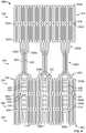
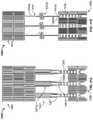
- Stent 100generally includes one or more rows of distal cells 102 , at least one support strut 104 , one or more rows of proximal cells 106 , at least one elongated support post 108 , and at least one post connection 110 coupling a support post 108 to at least some of the proximal cells 106 .
- One or more support struts 104connect distal cells 102 to proximal cells 106 .
- three support struts 104may interconnect proximal cells 106 and distal cells 102 .
- Stent 100may nonetheless include more or fewer support struts 104 .
- Support struts 104interconnect distal cells 102 and proximal cells 106 .
- stent 100may include one or more support struts 104 .
- stent 100may include one support strut 104 for every five proximal cells 106 .
- Stent 100may also include one support strut 104 for every seven distal cells 102 .
- these ratiosare not critical, and will depend on the size of proximal cells 106 and distal cells 102 , the desired stiffness of stent 100 and other considerations.
- Each support strut 104has a first end portion 104 a , a second end portion 104 b , and a middle portion 104 c located between the first and second end portions.
- the first end portion 104 a of each support strut 104is connected to the proximal end 102 b of a distal cell 102 .
- the second end portion 104 b of each support strut 104is connected to the distal end 106 a of a proximal cell 106 .
- a single support strut 104may couple a single distal cell 102 to a single proximal cell 106 .
- a usermay place a stent 100 (or any other stent disclosed herein) using any conventional methods. For instance, the user may first place stent 100 in a crimped condition and then insert it into a delivery instrument or system. The delivery instrument may be advanced through the patient's vasculature or through a transapical procedure until stent 100 reaches the desired destination near the aortic valve. Subsequently, the user deploys and expands stent 100 at the target site.
- the structure of stent 100 described aboveprovides very flexible support posts 108 which reduce the maximum amount of stress at the commissural interfaces on valve cycling. That is, since the distal ends of the support posts 108 are free from connections to the proximal cells 106 , these ends can move freely like a cantilever beam.
- Support struts 207each have a first end portion 207 a , a second end portion 207 b , and a middle portion 207 c between the first and second end portions.
- Each support strut 207includes a bifurcated section 207 d extending from the middle portion 207 c to the first end portion 207 a .
- Bifurcated section 207 d of each support strut 207includes two branches 207 e , 207 f .
- proximal cells 206are connected to an elongated support post 208 .
- one or more elongated support posts 208may extend beyond the first end 238 collectively defined by all the proximal cells 206 but may not extend past the second end 240 .
- Stent 200may have, for example, one elongated post 208 for every six proximal cells 206 .
- Post connections 310may be positioned at two locations along each elongated support post 308 . As noted above, such positioning reduces post flexibility and the strains experienced in post connections 310 .
- Two post connections 310may be positioned on opposite sides of the proximal end 308 b of an elongated support post 308 and join the elongated support post 308 to the proximal ends 306 b of certain proximal cells 306 in the second row 328 .
- Another two post connections 310may be located on opposite sides at or near the middle 308 c of an elongated support post 308 and join the middle of the support post to the middle portions 306 c of certain proximal cells 306 in the first row 324 .
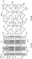
- Distal cells 602may be arranged in one or more longitudinal rows.
- stent 600 Amay include only one row 614 of distal cells 602 .
- Each distal cell 602has a distal end 602 a and a proximal end 602 b , and may have a diamond shape upon expansion.
- Distal cells 602are connected to one another along row 614 via cell connections 618 .
- Each cell connection 618is positioned at a valley formed between two adjacent distal cells 602 .
- the proximal ends 602 b of distal cells 602may be coupled in an alternating pattern to two different kinds of support struts 604 and 605 .
- Each distal cell 802has a distal end 802 a and a proximal end 802 b . All distal cells 802 are arranged in one or more longitudinal rows 814 . Cell connections 818 join adjacent distal cells 802 in the same row 814 . In the embodiment shown in FIGS. 9A and 9B , stent 800 includes only one row 814 .
- Each proximal cell 806may have an inverted arrow shape upon expansion defined by a pair of peaks 806 a on opposite sides of a valley 806 b in one stent section, another pair of peaks 806 a on opposite sides of a valley 806 b in another stent section, and a pair of bars 850 connecting the stent sections together.
- Proximal cells 806may be arranged in one or more longitudinal rows.
- stent 800includes proximal cells 806 in a first row 824 and in a second row 826 .
- Cell connections 830interconnect adjacent proximal cells 806 positioned in the same row.
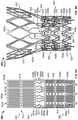
- stent 1300is substantially similar to the stent 1100 shown in FIG. 11A .
- Stent 1300includes distal cells 1302 , proximal cells 1306 , at least one elongated support post 1308 attached between the proximal cells 1306 , and at least one support strut array 1304 connecting the distal cells 1302 to the elongated support post 1308 .
- Each support strut array 1304includes one or more support struts 1307 . In the embodiment illustrated in FIG. 11C , each support strut array 1304 includes two support struts 1307 .
- Eyelets 1532extend from the distal end 1509 a of elongated support post 1509 along the section located distally of the reduced width portion 1509 d .
- Reduced width portion 1509 d and base portion 1509 edo not have eyelets 1532 .
- Base portion 1509 eis wider than reduced width portion 1509 d and may have a rectangular or paddle shape. In use, base portion 1509 e may function as an interlocking feature configured to be attached to a delivery system or another valve.
- stent 1500may alternatively incorporate elongated support post 1511 , which is substantially similar to elongated support post 1509 .
- Elongated support post 1511is narrower than both the shortened support post 1508 of FIG. 12A and the elongated support post 1509 of FIG. 12B , thus enabling an even smaller overall diameter when crimped.
- elongated support post 1511has a reduced width portion 1511 d , a base portion 1511 e and a plurality of merged eyelets 1533 .
- Merged eyelets 1533constitute two eyelets 1532 as shown in FIG. 12B merged together. Eyelets 1533 are larger than eyelets 1532 of FIG. 12A , thus making elongated support post 1511 more flexible than elongated support post 1509 .
- Base portion 1511 ecan function as an interlocking feature configured to be attached to a delivery system or another valve.
- FIG. 14Ashows a stent 1700 in a flat, rolled out, unexpanded condition
- FIG. 14Billustrates stent 1700 in a flat, rolled out, expanded condition
- Stent 1700is substantially similar to stent 1600 but does not include a sliding mechanism. Instead, stent 1700 includes an elongated support post 1708 having a collapsible feature 1760 which enables the length of the support post to shorten upon expansion of the stent. As with previous embodiments, elongated support post 1708 has a distal end 1708 a , a proximal end 1708 b , and a middle 1708 c . In addition, elongated support post 1708 includes eyelets or apertures 1732 .
- FIGS. 18A, 18B, and 18Cshow a stent 2100 which is substantially similar to stent 100 shown in FIG. 2 .
- Stent 2100includes support struts 2104 connected to proximal cells 2106 located midway between two elongated support posts 2108 .
- FIG. 18Aillustrates stent 2100 in a flat, rolled out, unexpanded condition
- FIG. 18Bshows stent 2100 perspectively in a fully expanded and deployed condition
- FIG. 18Cdepicts stent 2100 perspectively in an unexpanded condition.
- Each support strut 2104has a distal end 2104 a , a proximal end 2104 b and a middle portion 2104 c between the distal end and the proximal end.
- the distal end 2104 a of each support strut 2104is connected to a distal cell 2102 .
- the proximal end 2104 b of each support strut 2104is connected to a proximal cell 2106 .
- each support strut 2104is connected to a proximal cell 2106 f located midway between two elongated support posts 2108 in order to increase flexibility and minimize the dynamic loads exerted on the elongated support posts.
- Stent 2100may include at least three support struts 2104 connected to three proximal cells 2106 f , as seen in FIGS. 18A, 18B and 18C , for providing a stable connection of the aorta portion to the annulus portion while providing the greatest amount of stent frame flexibility.
- stent 2100has the same number of support struts 2104 as elongated support posts 2108 .
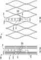
- FIGS. 20A and 20Bshow additional physiological concerns due to translational (shortening or lengthening) motion and the bending and straightening of the ascending aorta.
- the type and locations of the support struts 2104 of stent 2100also aid in maintaining proper physiological motion, reduce leaflet stress, improve relatively independent valve function, and reduce certain stent strains, all while maintaining the necessary valve anchoring.
- FIG. 20Aillustrates the ability of stent 2100 to conform to an aortic arch bend with little effect on its valve-functioning part (i.e., proximal cells 2106 ).
- FIG. 20Bshows stent 2100 with the valve section (i.e., proximal cells 2106 ) functioning relatively free of adverse contortion from shortening and lengthening motions of the relative anatomical structures.
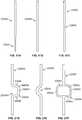
- FIG. 21Ashows a support strut 2204 A with a tapered proximal portion 2204 t .
- FIG. 21Billustrates a support strut 2204 B featuring a uniform diameter or cross-section along its entire length.
- FIG. 21Cdepicts a support strut 2204 C with a tapered middle portion 2204 k .
- the support struts shown in FIGS. 21A, 21B, and 21Ccan bend and twist but cannot elongate.
- FIG. 21Iillustrates a support strut 2204 I with a single serpentine or sinusoidal link 2204 y in its middle portion.
- Support strut 2204 Ican bend and twist and can also elongate more easily than previous embodiments.
- FIG. 21Jshows a pair of support struts 2204 J each having serpentine-shaped links 2204 z in their middle portions.
- the serpentine-shaped link 2204 z of one support strut 2204 Jis offset to the left (or away from the other support strut 2204 J), while the serpentine-shaped link 2204 z of the other support strut 2204 J is offset to the right (or away from the other support strut 2204 J).
- Stentsmay not only have both an annular portion (i.e., proximal cells) and an aortic/sinotubular junction portion (i.e., distal cells), but may alternatively have independently contouring support struts to conform to the differences in anatomy/physiology around the circumference of the aortic root. This can help to anchor the valve with the least amount of unwanted load transfer to the support post area of the valve.
- each support strut 2304has a curved profile 2304 c near its distal end 2304 a .
- the curved profiles 2304 cinitially bend outwardly or away from one another to anchor just distally of the sinotubular junction, but, closer to the distal ends 2304 a , the curved profiles 2304 c bend inwardly or toward one another to reduce the possibility of aortic perforation or dissection by a support strut 2304 .
- a single stent 2300may have the support struts shown in both FIGS. 23A and 23B . Additionally, support struts 2304 may be used to latch onto features of previously implanted prosthetic valves, such as the spacer 770 shown in FIGS. 8A and 8B .
- FIG. 25shows how the curved profile 2304 d of the support strut 2304 shown in FIG. 23B can be contoured to fasten above the stenotic leaflets or prosthetic valve 6 and below the sinotubular junction 4 .
- the curved profile or anchoring feature 2304 d of stent 2300anchors to the aortic root, thereby minimizing migration.
- a fabric or tissue layer Tmay be attached to the interior of stent 2300
- a leaflet Lmay be attached to the tissue layer.
- the tissue layer T and the leaflet Lact as a valve, preventing or least hindering backflow when in the closed condition, as indicated by arrow F.
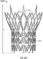
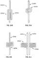
- FIG. 26is a top view of a stent 2500 having a support post 2508 and secondary posts 2510 used for reinforcement.
- Secondary posts 2510may be made from a material, such as stainless steel, which is more resistant to fatigue than Nitinol, from which stent 2500 may be made.
- Support post 2508has at least two eyelets or apertures 2532 .
- Each secondary post 2512has two eyelets 2512 oriented substantially perpendicular to each other in a crossing pattern.
- Secondary posts 2510may be attached to support post 2508 using sutures S.
- One suture Spasses through one eyelet 2532 of support post 2508 and through a corresponding eyelet 2512 of one secondary post 2510 , thereby attaching that secondary post to the support post.
- Another suture Spasses through another eyelet 2532 of support post 2508 and through a corresponding eyelet 2512 of the other secondary post 2510 , thereby attaching that secondary post to the support post.
- both secondary posts 2510are attached to support post 2508 with sutures S.
- FIG. 31Ashows a pliable reinforcement 3000 folded over a free edge of a leaflet and sutured to itself and to the stent frame or post.
- reinforcement 3000may be attached to a free edge of a leaflet at the commissure 9 , but away from the belly region 8 of the valve leaflet, as shown in FIG. 31A .
- reinforcement 3000may be attached to the entire sutured edge of the leaflet, which would result in the shape seen in FIG. 31B .
Landscapes
- Health & Medical Sciences (AREA)
- Engineering & Computer Science (AREA)
- Biomedical Technology (AREA)
- Cardiology (AREA)
- Oral & Maxillofacial Surgery (AREA)
- Transplantation (AREA)
- Heart & Thoracic Surgery (AREA)
- Vascular Medicine (AREA)
- Life Sciences & Earth Sciences (AREA)
- Animal Behavior & Ethology (AREA)
- General Health & Medical Sciences (AREA)
- Public Health (AREA)
- Veterinary Medicine (AREA)
- Physics & Mathematics (AREA)
- Optics & Photonics (AREA)
- Prostheses (AREA)
Abstract
Description
- Flexibility of Stent Via Post Connections
Claims (17)
Priority Applications (1)
| Application Number | Priority Date | Filing Date | Title |
|---|---|---|---|
| US16/562,726US11045314B2 (en) | 2009-02-27 | 2019-09-06 | Stent features for collapsible prosthetic heart valves |
Applications Claiming Priority (7)
| Application Number | Priority Date | Filing Date | Title |
|---|---|---|---|
| US20883409P | 2009-02-27 | 2009-02-27 | |
| PCT/US2010/000561WO2010098857A1 (en) | 2009-02-27 | 2010-02-25 | Stent features for collapsible prosthetic heart valves |
| US201113203627A | 2011-12-07 | 2011-12-07 | |
| US14/304,293US9387072B2 (en) | 2009-02-27 | 2014-06-13 | Stent features for collapsible prosthetic heart valves |
| US15/181,708US9901447B2 (en) | 2009-02-27 | 2016-06-14 | Stent features for collapsible prosthetic heart valves |
| US15/868,031US10441417B2 (en) | 2009-02-27 | 2018-01-11 | Stent features for collapsible prosthetic heart valves |
| US16/562,726US11045314B2 (en) | 2009-02-27 | 2019-09-06 | Stent features for collapsible prosthetic heart valves |
Related Parent Applications (1)
| Application Number | Title | Priority Date | Filing Date |
|---|---|---|---|
| US15/868,031ContinuationUS10441417B2 (en) | 2009-02-27 | 2018-01-11 | Stent features for collapsible prosthetic heart valves |
Publications (2)
| Publication Number | Publication Date |
|---|---|
| US20190388224A1 US20190388224A1 (en) | 2019-12-26 |
| US11045314B2true US11045314B2 (en) | 2021-06-29 |
Family
ID=42173856
Family Applications (5)
| Application Number | Title | Priority Date | Filing Date |
|---|---|---|---|
| US13/203,627Active2031-05-14US8808366B2 (en) | 2009-02-27 | 2010-02-25 | Stent features for collapsible prosthetic heart valves |
| US14/304,293Active2030-08-06US9387072B2 (en) | 2009-02-27 | 2014-06-13 | Stent features for collapsible prosthetic heart valves |
| US15/181,708ActiveUS9901447B2 (en) | 2009-02-27 | 2016-06-14 | Stent features for collapsible prosthetic heart valves |
| US15/868,031Active2030-04-11US10441417B2 (en) | 2009-02-27 | 2018-01-11 | Stent features for collapsible prosthetic heart valves |
| US16/562,726Active2030-06-23US11045314B2 (en) | 2009-02-27 | 2019-09-06 | Stent features for collapsible prosthetic heart valves |
Family Applications Before (4)
| Application Number | Title | Priority Date | Filing Date |
|---|---|---|---|
| US13/203,627Active2031-05-14US8808366B2 (en) | 2009-02-27 | 2010-02-25 | Stent features for collapsible prosthetic heart valves |
| US14/304,293Active2030-08-06US9387072B2 (en) | 2009-02-27 | 2014-06-13 | Stent features for collapsible prosthetic heart valves |
| US15/181,708ActiveUS9901447B2 (en) | 2009-02-27 | 2016-06-14 | Stent features for collapsible prosthetic heart valves |
| US15/868,031Active2030-04-11US10441417B2 (en) | 2009-02-27 | 2018-01-11 | Stent features for collapsible prosthetic heart valves |
Country Status (7)
| Country | Link |
|---|---|
| US (5) | US8808366B2 (en) |
| EP (1) | EP2400924B1 (en) |
| JP (3) | JP5659168B2 (en) |
| AU (1) | AU2010218384B2 (en) |
| BR (1) | BRPI1008902A2 (en) |
| CR (1) | CR20110451A (en) |
| WO (1) | WO2010098857A1 (en) |
Families Citing this family (415)
| Publication number | Priority date | Publication date | Assignee | Title |
|---|---|---|---|---|
| EP1309289A2 (en) | 2000-08-18 | 2003-05-14 | Atritech, Inc. | Expandable implant devices for filtering blood flow from atrial appendages |
| US9579194B2 (en)* | 2003-10-06 | 2017-02-28 | Medtronic ATS Medical, Inc. | Anchoring structure with concave landing zone |
| US20050137687A1 (en) | 2003-12-23 | 2005-06-23 | Sadra Medical | Heart valve anchor and method |
| US7959666B2 (en) | 2003-12-23 | 2011-06-14 | Sadra Medical, Inc. | Methods and apparatus for endovascularly replacing a heart valve |
| US8840663B2 (en) | 2003-12-23 | 2014-09-23 | Sadra Medical, Inc. | Repositionable heart valve method |
| US8828078B2 (en) | 2003-12-23 | 2014-09-09 | Sadra Medical, Inc. | Methods and apparatus for endovascular heart valve replacement comprising tissue grasping elements |
| US8603160B2 (en) | 2003-12-23 | 2013-12-10 | Sadra Medical, Inc. | Method of using a retrievable heart valve anchor with a sheath |
| US8579962B2 (en) | 2003-12-23 | 2013-11-12 | Sadra Medical, Inc. | Methods and apparatus for performing valvuloplasty |
| US7381219B2 (en) | 2003-12-23 | 2008-06-03 | Sadra Medical, Inc. | Low profile heart valve and delivery system |
| US11278398B2 (en) | 2003-12-23 | 2022-03-22 | Boston Scientific Scimed, Inc. | Methods and apparatus for endovascular heart valve replacement comprising tissue grasping elements |
| US9526609B2 (en) | 2003-12-23 | 2016-12-27 | Boston Scientific Scimed, Inc. | Methods and apparatus for endovascularly replacing a patient's heart valve |
| US20120041550A1 (en) | 2003-12-23 | 2012-02-16 | Sadra Medical, Inc. | Methods and Apparatus for Endovascular Heart Valve Replacement Comprising Tissue Grasping Elements |
| US8343213B2 (en) | 2003-12-23 | 2013-01-01 | Sadra Medical, Inc. | Leaflet engagement elements and methods for use thereof |
| JP5219518B2 (en) | 2004-12-09 | 2013-06-26 | ザ ファウンドリー, エルエルシー | Aortic valve repair |
| DE102005003632A1 (en) | 2005-01-20 | 2006-08-17 | Fraunhofer-Gesellschaft zur Förderung der angewandten Forschung e.V. | Catheter for the transvascular implantation of heart valve prostheses |
| US8608797B2 (en) | 2005-03-17 | 2013-12-17 | Valtech Cardio Ltd. | Mitral valve treatment techniques |
| US8333777B2 (en) | 2005-04-22 | 2012-12-18 | Benvenue Medical, Inc. | Catheter-based tissue remodeling devices and methods |
| US8951285B2 (en) | 2005-07-05 | 2015-02-10 | Mitralign, Inc. | Tissue anchor, anchoring system and methods of using the same |
| CA2881760C (en) | 2005-11-10 | 2017-06-13 | Arshad Quadri | Balloon-expandable, self-expanding, vascular prosthesis connecting stent |
| US20070213813A1 (en) | 2005-12-22 | 2007-09-13 | Symetis Sa | Stent-valves for valve replacement and associated methods and systems for surgery |
| EP1988851A2 (en) | 2006-02-14 | 2008-11-12 | Sadra Medical, Inc. | Systems and methods for delivering a medical implant |
| US8652201B2 (en)* | 2006-04-26 | 2014-02-18 | The Cleveland Clinic Foundation | Apparatus and method for treating cardiovascular diseases |
| US11259924B2 (en) | 2006-12-05 | 2022-03-01 | Valtech Cardio Ltd. | Implantation of repair devices in the heart |
| US9883943B2 (en) | 2006-12-05 | 2018-02-06 | Valtech Cardio, Ltd. | Implantation of repair devices in the heart |
| US11660190B2 (en) | 2007-03-13 | 2023-05-30 | Edwards Lifesciences Corporation | Tissue anchors, systems and methods, and devices |
| US7896915B2 (en) | 2007-04-13 | 2011-03-01 | Jenavalve Technology, Inc. | Medical device for treating a heart valve insufficiency |
| DE102007034363A1 (en)* | 2007-07-24 | 2009-01-29 | Biotronik Vi Patent Ag | endoprosthesis |
| US8728154B2 (en) | 2007-08-24 | 2014-05-20 | St. Jude Medical, Inc. | Prosthetic aortic heart valves |
| DE102007043830A1 (en) | 2007-09-13 | 2009-04-02 | Lozonschi, Lucian, Madison | Heart valve stent |
| EP3443938B1 (en) | 2007-09-26 | 2024-01-24 | St. Jude Medical, LLC | Collapsible prosthetic heart valves |
| US9532868B2 (en) | 2007-09-28 | 2017-01-03 | St. Jude Medical, Inc. | Collapsible-expandable prosthetic heart valves with structures for clamping native tissue |
| WO2009045334A1 (en) | 2007-09-28 | 2009-04-09 | St. Jude Medical, Inc. | Collapsible/expandable prosthetic heart valves with native calcified leaflet retention features |
| EP2679198B1 (en) | 2007-10-25 | 2021-03-24 | Symetis SA | Valved-stents and systems for delivery thereof |
| WO2009061389A2 (en)* | 2007-11-05 | 2009-05-14 | St. Jude Medical, Inc. | Collapsible/expandable prosthetic heart valves with non-expanding stent posts and retrieval features |
| US8715337B2 (en) | 2007-11-09 | 2014-05-06 | Cook Medical Technologies Llc | Aortic valve stent graft |
| WO2009067432A1 (en)* | 2007-11-19 | 2009-05-28 | Cook Incorporated | Valve frame |
| US8628566B2 (en)* | 2008-01-24 | 2014-01-14 | Medtronic, Inc. | Stents for prosthetic heart valves |
| US8157853B2 (en)* | 2008-01-24 | 2012-04-17 | Medtronic, Inc. | Delivery systems and methods of implantation for prosthetic heart valves |
| US9044318B2 (en) | 2008-02-26 | 2015-06-02 | Jenavalve Technology Gmbh | Stent for the positioning and anchoring of a valvular prosthesis |
| BR112012021347A2 (en) | 2008-02-26 | 2019-09-24 | Jenavalve Tecnology Inc | stent for positioning and anchoring a valve prosthesis at an implantation site in a patient's heart |
| US8382829B1 (en) | 2008-03-10 | 2013-02-26 | Mitralign, Inc. | Method to reduce mitral regurgitation by cinching the commissure of the mitral valve |
| US20090276040A1 (en)* | 2008-05-01 | 2009-11-05 | Edwards Lifesciences Corporation | Device and method for replacing mitral valve |
| EP2815724B2 (en) | 2008-07-15 | 2024-03-13 | St. Jude Medical, Inc. | Collapsible and re-expandable prosthetic heart valve cuff designs and complementary technological applications |
| US8652202B2 (en)* | 2008-08-22 | 2014-02-18 | Edwards Lifesciences Corporation | Prosthetic heart valve and delivery apparatus |
| CN102292053A (en) | 2008-09-29 | 2011-12-21 | 卡迪尔克阀门技术公司 | Heart valve |
| WO2010040009A1 (en) | 2008-10-01 | 2010-04-08 | Cardiaq Valve Technologies, Inc. | Delivery system for vascular implant |
| EP3238661B1 (en) | 2008-10-10 | 2019-05-22 | Boston Scientific Scimed, Inc. | Medical devices and delivery systems for delivering medical devices |
| WO2010073246A2 (en) | 2008-12-22 | 2010-07-01 | Valtech Cardio, Ltd. | Adjustable annuloplasty devices and adjustment mechanisms therefor |
| US8911494B2 (en) | 2009-05-04 | 2014-12-16 | Valtech Cardio, Ltd. | Deployment techniques for annuloplasty ring |
| US10517719B2 (en) | 2008-12-22 | 2019-12-31 | Valtech Cardio, Ltd. | Implantation of repair devices in the heart |
| US8241351B2 (en) | 2008-12-22 | 2012-08-14 | Valtech Cardio, Ltd. | Adjustable partial annuloplasty ring and mechanism therefor |
| US8715342B2 (en) | 2009-05-07 | 2014-05-06 | Valtech Cardio, Ltd. | Annuloplasty ring with intra-ring anchoring |
| US8353956B2 (en) | 2009-02-17 | 2013-01-15 | Valtech Cardio, Ltd. | Actively-engageable movement-restriction mechanism for use with an annuloplasty structure |
| AU2010218384B2 (en) | 2009-02-27 | 2014-11-20 | St. Jude Medical, Inc. | Stent features for collapsible prosthetic heart valves |
| CA2961053C (en) | 2009-04-15 | 2019-04-30 | Edwards Lifesciences Cardiaq Llc | Vascular implant and delivery system |
| US9968452B2 (en) | 2009-05-04 | 2018-05-15 | Valtech Cardio, Ltd. | Annuloplasty ring delivery cathethers |
| CN102481190A (en)* | 2009-06-05 | 2012-05-30 | 美敦力Ats医药股份有限公司 | Flexible commissure structure for attaching valve bioprosthesis |
| US8652203B2 (en)* | 2010-09-23 | 2014-02-18 | Cardiaq Valve Technologies, Inc. | Replacement heart valves, delivery devices and methods |
| US9730790B2 (en) | 2009-09-29 | 2017-08-15 | Edwards Lifesciences Cardiaq Llc | Replacement valve and method |
| US9180007B2 (en) | 2009-10-29 | 2015-11-10 | Valtech Cardio, Ltd. | Apparatus and method for guide-wire based advancement of an adjustable implant |
| US10098737B2 (en) | 2009-10-29 | 2018-10-16 | Valtech Cardio, Ltd. | Tissue anchor for annuloplasty device |
| US8734467B2 (en) | 2009-12-02 | 2014-05-27 | Valtech Cardio, Ltd. | Delivery tool for implantation of spool assembly coupled to a helical anchor |
| EP3300695B1 (en) | 2009-12-08 | 2023-05-24 | Avalon Medical Ltd. | Device and system for transcatheter mitral valve replacement |
| US8870950B2 (en) | 2009-12-08 | 2014-10-28 | Mitral Tech Ltd. | Rotation-based anchoring of an implant |
| US9307980B2 (en) | 2010-01-22 | 2016-04-12 | 4Tech Inc. | Tricuspid valve repair using tension |
| US10058323B2 (en) | 2010-01-22 | 2018-08-28 | 4 Tech Inc. | Tricuspid valve repair using tension |
| US8475525B2 (en) | 2010-01-22 | 2013-07-02 | 4Tech Inc. | Tricuspid valve repair using tension |
| US10433956B2 (en)* | 2010-02-24 | 2019-10-08 | Medtronic Ventor Technologies Ltd. | Mitral prosthesis and methods for implantation |
| US9522062B2 (en) | 2010-02-24 | 2016-12-20 | Medtronic Ventor Technologies, Ltd. | Mitral prosthesis and methods for implantation |
| US20110224785A1 (en) | 2010-03-10 | 2011-09-15 | Hacohen Gil | Prosthetic mitral valve with tissue anchors |
| US9480557B2 (en)* | 2010-03-25 | 2016-11-01 | Medtronic, Inc. | Stents for prosthetic heart valves |
| WO2011120050A1 (en)* | 2010-03-26 | 2011-09-29 | Thubrikar Aortic Valve, Inc. | Valve component, frame component and prosthetic valve device including the same for implantation in a body lumen |
| US8579964B2 (en) | 2010-05-05 | 2013-11-12 | Neovasc Inc. | Transcatheter mitral valve prosthesis |
| US10856978B2 (en) | 2010-05-20 | 2020-12-08 | Jenavalve Technology, Inc. | Catheter system |
| WO2011147849A1 (en) | 2010-05-25 | 2011-12-01 | Jenavalve Technology Inc. | Prosthetic heart valve and transcatheter delivered endoprosthesis comprising a prosthetic heart valve and a stent |
| US9795476B2 (en) | 2010-06-17 | 2017-10-24 | St. Jude Medical, Llc | Collapsible heart valve with angled frame |
| US9763657B2 (en) | 2010-07-21 | 2017-09-19 | Mitraltech Ltd. | Techniques for percutaneous mitral valve replacement and sealing |
| US11653910B2 (en) | 2010-07-21 | 2023-05-23 | Cardiovalve Ltd. | Helical anchor implantation |
| US9039759B2 (en) | 2010-08-24 | 2015-05-26 | St. Jude Medical, Cardiology Division, Inc. | Repositioning of prosthetic heart valve and deployment |
| US8814931B2 (en) | 2010-08-24 | 2014-08-26 | St. Jude Medical, Cardiology Division, Inc. | Staged deployment devices and methods for transcatheter heart valve delivery systems |
| AU2011300644B2 (en) | 2010-09-10 | 2015-08-20 | Symetis Sa | Valve replacement devices and a system comprising the valve replacement device and a delivery device therefor |
| WO2012036741A2 (en) | 2010-09-17 | 2012-03-22 | St. Jude Medical, Cardiology Division, Inc. | Staged deployment devices and methods for transcatheter heart valve delivery |
| USD653343S1 (en) | 2010-09-20 | 2012-01-31 | St. Jude Medical, Inc. | Surgical cuff |
| USD653342S1 (en) | 2010-09-20 | 2012-01-31 | St. Jude Medical, Inc. | Stent connections |
| USD660432S1 (en) | 2010-09-20 | 2012-05-22 | St. Jude Medical, Inc. | Commissure point |
| USD652926S1 (en) | 2010-09-20 | 2012-01-24 | St. Jude Medical, Inc. | Forked end |
| USD652927S1 (en) | 2010-09-20 | 2012-01-24 | St. Jude Medical, Inc. | Surgical stent |
| USD648854S1 (en) | 2010-09-20 | 2011-11-15 | St. Jude Medical, Inc. | Commissure points |
| AU2011306028B2 (en) | 2010-09-20 | 2014-07-17 | St. Jude Medical, Cardiology Division, Inc. | Valve leaflet attachment in collapsible prosthetic valves |
| USD684692S1 (en) | 2010-09-20 | 2013-06-18 | St. Jude Medical, Inc. | Forked ends |
| USD654170S1 (en) | 2010-09-20 | 2012-02-14 | St. Jude Medical, Inc. | Stent connections |
| USD654169S1 (en) | 2010-09-20 | 2012-02-14 | St. Jude Medical Inc. | Forked ends |
| USD660967S1 (en) | 2010-09-20 | 2012-05-29 | St. Jude Medical, Inc. | Surgical stent |
| USD660433S1 (en) | 2010-09-20 | 2012-05-22 | St. Jude Medical, Inc. | Surgical stent assembly |
| USD653341S1 (en) | 2010-09-20 | 2012-01-31 | St. Jude Medical, Inc. | Surgical stent |
| DK4233795T3 (en) | 2010-10-05 | 2024-08-26 | Edwards Lifesciences Corp | Prosthetic heart valve |
| EP2629699B1 (en)* | 2010-10-21 | 2017-01-04 | Medtronic, Inc. | Mitral bioprosthesis with low ventricular profile |
| US20120116496A1 (en) | 2010-11-05 | 2012-05-10 | Chuter Timothy A | Stent structures for use with valve replacements |
| CA2822381C (en) | 2010-12-23 | 2019-04-02 | Foundry Newco Xii, Inc. | System for mitral valve repair and replacement |
| EP2478868A1 (en)* | 2011-01-25 | 2012-07-25 | The Provost, Fellows, Foundation Scholars, and the other Members of Board, of the College of the Holy and Undivided Trinity of Queen Elizabeth | Implant device |
| US9717593B2 (en) | 2011-02-01 | 2017-08-01 | St. Jude Medical, Cardiology Division, Inc. | Leaflet suturing to commissure points for prosthetic heart valve |
| US9155619B2 (en)* | 2011-02-25 | 2015-10-13 | Edwards Lifesciences Corporation | Prosthetic heart valve delivery apparatus |
| US9554897B2 (en) | 2011-04-28 | 2017-01-31 | Neovasc Tiara Inc. | Methods and apparatus for engaging a valve prosthesis with tissue |
| US9308087B2 (en) | 2011-04-28 | 2016-04-12 | Neovasc Tiara Inc. | Sequentially deployed transcatheter mitral valve prosthesis |
| EP2520251A1 (en) | 2011-05-05 | 2012-11-07 | Symetis SA | Method and Apparatus for Compressing Stent-Valves |
| EP2713905B1 (en)* | 2011-06-03 | 2022-03-16 | Pulsar Vascular, Inc. | Systems for enclosing an anatomical opening, including shock absorbing aneurysm devices |
| US10285798B2 (en) | 2011-06-03 | 2019-05-14 | Merit Medical Systems, Inc. | Esophageal stent |
| EP2720641B1 (en) | 2011-06-15 | 2019-02-20 | St. Jude Medical, LLC | Prosthetic heart valve with multi-layer stent |
| JP5872692B2 (en) | 2011-06-21 | 2016-03-01 | トゥエルヴ, インコーポレイテッド | Artificial therapy device |
| US10792152B2 (en) | 2011-06-23 | 2020-10-06 | Valtech Cardio, Ltd. | Closed band for percutaneous annuloplasty |
| EP3345573B1 (en) | 2011-06-23 | 2020-01-29 | Valtech Cardio, Ltd. | Closure element for use with annuloplasty structure |
| US9918840B2 (en) | 2011-06-23 | 2018-03-20 | Valtech Cardio, Ltd. | Closed band for percutaneous annuloplasty |
| US8998976B2 (en) | 2011-07-12 | 2015-04-07 | Boston Scientific Scimed, Inc. | Coupling system for medical devices |
| EP2734157B1 (en) | 2011-07-21 | 2018-09-05 | 4Tech Inc. | Apparatus for tricuspid valve repair using tension |
| US20140324164A1 (en) | 2011-08-05 | 2014-10-30 | Mitraltech Ltd. | Techniques for percutaneous mitral valve replacement and sealing |
| WO2013021374A2 (en) | 2011-08-05 | 2013-02-14 | Mitraltech Ltd. | Techniques for percutaneous mitral valve replacement and sealing |
| EP2739214B1 (en) | 2011-08-05 | 2018-10-10 | Cardiovalve Ltd | Percutaneous mitral valve replacement and sealing |
| US8852272B2 (en) | 2011-08-05 | 2014-10-07 | Mitraltech Ltd. | Techniques for percutaneous mitral valve replacement and sealing |
| EP4289398A3 (en) | 2011-08-11 | 2024-03-13 | Tendyne Holdings, Inc. | Improvements for prosthetic valves and related inventions |
| US9060860B2 (en) | 2011-08-18 | 2015-06-23 | St. Jude Medical, Cardiology Division, Inc. | Devices and methods for transcatheter heart valve delivery |
| EA201400478A1 (en)* | 2011-10-19 | 2014-10-30 | Твелв, Инк. | DEVICES, SYSTEMS AND METHODS OF PROTESIZING THE HEART VALVE |
| JP6133309B2 (en) | 2011-10-19 | 2017-05-24 | トゥエルヴ, インコーポレイテッド | Prosthetic heart valve device |
| US9763780B2 (en) | 2011-10-19 | 2017-09-19 | Twelve, Inc. | Devices, systems and methods for heart valve replacement |
| US9655722B2 (en) | 2011-10-19 | 2017-05-23 | Twelve, Inc. | Prosthetic heart valve devices, prosthetic mitral valves and associated systems and methods |
| US9039757B2 (en) | 2011-10-19 | 2015-05-26 | Twelve, Inc. | Prosthetic heart valve devices, prosthetic mitral valves and associated systems and methods |
| US11202704B2 (en) | 2011-10-19 | 2021-12-21 | Twelve, Inc. | Prosthetic heart valve devices, prosthetic mitral valves and associated systems and methods |
| US8986368B2 (en) | 2011-10-31 | 2015-03-24 | Merit Medical Systems, Inc. | Esophageal stent with valve |
| US8858623B2 (en) | 2011-11-04 | 2014-10-14 | Valtech Cardio, Ltd. | Implant having multiple rotational assemblies |
| EP3656434B1 (en) | 2011-11-08 | 2021-10-20 | Valtech Cardio, Ltd. | Controlled steering functionality for implant-delivery tool |
| CN104114127B (en)* | 2011-12-09 | 2017-09-05 | 爱德华兹生命科学公司 | Prosthetic heart valve with improved commissural support |
| EP2881083B1 (en) | 2011-12-12 | 2017-03-22 | David Alon | Heart valve repair device |
| US9827092B2 (en) | 2011-12-16 | 2017-11-28 | Tendyne Holdings, Inc. | Tethers for prosthetic mitral valve |
| WO2013112547A1 (en) | 2012-01-25 | 2013-08-01 | Boston Scientific Scimed, Inc. | Valve assembly with a bioabsorbable gasket and a replaceable valve implant |
| EP3281608B1 (en) | 2012-02-10 | 2020-09-16 | CVDevices, LLC | Medical product comprising a frame and visceral pleura |
| US9579198B2 (en) | 2012-03-01 | 2017-02-28 | Twelve, Inc. | Hydraulic delivery systems for prosthetic heart valve devices and associated methods |
| US8992595B2 (en)* | 2012-04-04 | 2015-03-31 | Trivascular, Inc. | Durable stent graft with tapered struts and stable delivery methods and devices |
| US9427315B2 (en) | 2012-04-19 | 2016-08-30 | Caisson Interventional, LLC | Valve replacement systems and methods |
| US9011515B2 (en) | 2012-04-19 | 2015-04-21 | Caisson Interventional, LLC | Heart valve assembly systems and methods |
| CA2871153A1 (en)* | 2012-05-09 | 2013-11-14 | Boston Scientific Scimed, Inc. | Reduced profile valve with locking elements |
| US9345573B2 (en) | 2012-05-30 | 2016-05-24 | Neovasc Tiara Inc. | Methods and apparatus for loading a prosthesis onto a delivery system |
| US8961594B2 (en) | 2012-05-31 | 2015-02-24 | 4Tech Inc. | Heart valve repair system |
| KR102313261B1 (en) | 2012-06-05 | 2021-10-14 | 메리트 메디컬 시스템즈, 인크. | Esophageal stent |
| US9883941B2 (en) | 2012-06-19 | 2018-02-06 | Boston Scientific Scimed, Inc. | Replacement heart valve |
| US9554902B2 (en) | 2012-06-28 | 2017-01-31 | St. Jude Medical, Cardiology Division, Inc. | Leaflet in configuration for function in various shapes and sizes |
| US9289292B2 (en) | 2012-06-28 | 2016-03-22 | St. Jude Medical, Cardiology Division, Inc. | Valve cuff support |
| US9241791B2 (en) | 2012-06-29 | 2016-01-26 | St. Jude Medical, Cardiology Division, Inc. | Valve assembly for crimp profile |
| US9615920B2 (en) | 2012-06-29 | 2017-04-11 | St. Jude Medical, Cardiology Divisions, Inc. | Commissure attachment feature for prosthetic heart valve |
| US20140005776A1 (en) | 2012-06-29 | 2014-01-02 | St. Jude Medical, Cardiology Division, Inc. | Leaflet attachment for function in various shapes and sizes |
| US9808342B2 (en) | 2012-07-03 | 2017-11-07 | St. Jude Medical, Cardiology Division, Inc. | Balloon sizing device and method of positioning a prosthetic heart valve |
| US10004597B2 (en) | 2012-07-03 | 2018-06-26 | St. Jude Medical, Cardiology Division, Inc. | Stent and implantable valve incorporating same |
| WO2014022124A1 (en) | 2012-07-28 | 2014-02-06 | Tendyne Holdings, Inc. | Improved multi-component designs for heart valve retrieval device, sealing structures and stent assembly |
| WO2014021905A1 (en) | 2012-07-30 | 2014-02-06 | Tendyne Holdings, Inc. | Improved delivery systems and methods for transcatheter prosthetic valves |
| US9216018B2 (en) | 2012-09-29 | 2015-12-22 | Mitralign, Inc. | Plication lock delivery system and method of use thereof |
| US9801721B2 (en) | 2012-10-12 | 2017-10-31 | St. Jude Medical, Cardiology Division, Inc. | Sizing device and method of positioning a prosthetic heart valve |
| US10524909B2 (en) | 2012-10-12 | 2020-01-07 | St. Jude Medical, Cardiology Division, Inc. | Retaining cage to permit resheathing of a tavi aortic-first transapical system |
| EP2911593B1 (en) | 2012-10-23 | 2020-03-25 | Valtech Cardio, Ltd. | Percutaneous tissue anchor techniques |
| WO2014064694A2 (en) | 2012-10-23 | 2014-05-01 | Valtech Cardio, Ltd. | Controlled steering functionality for implant-delivery tool |
| US8628571B1 (en) | 2012-11-13 | 2014-01-14 | Mitraltech Ltd. | Percutaneously-deliverable mechanical valve |
| WO2014087402A1 (en) | 2012-12-06 | 2014-06-12 | Valtech Cardio, Ltd. | Techniques for guide-wire based advancement of a tool |
| CN105007832B (en) | 2013-01-09 | 2018-01-23 | 4科技有限公司 | Organize ancora equipment |
| US20150351906A1 (en) | 2013-01-24 | 2015-12-10 | Mitraltech Ltd. | Ventricularly-anchored prosthetic valves |
| US9186238B2 (en) | 2013-01-29 | 2015-11-17 | St. Jude Medical, Cardiology Division, Inc. | Aortic great vessel protection |
| US9314163B2 (en) | 2013-01-29 | 2016-04-19 | St. Jude Medical, Cardiology Division, Inc. | Tissue sensing device for sutureless valve selection |
| US9655719B2 (en) | 2013-01-29 | 2017-05-23 | St. Jude Medical, Cardiology Division, Inc. | Surgical heart valve flexible stent frame stiffener |
| CA2900862C (en)* | 2013-02-11 | 2017-10-03 | Cook Medical Technologies Llc | Expandable support frame and medical device |
| EP2961351B1 (en) | 2013-02-26 | 2018-11-28 | Mitralign, Inc. | Devices for percutaneous tricuspid valve repair |
| US9844435B2 (en) | 2013-03-01 | 2017-12-19 | St. Jude Medical, Cardiology Division, Inc. | Transapical mitral valve replacement |
| US9901470B2 (en) | 2013-03-01 | 2018-02-27 | St. Jude Medical, Cardiology Division, Inc. | Methods of repositioning a transcatheter heart valve after full deployment |
| EP2964148A4 (en) | 2013-03-05 | 2016-08-24 | Merit Medical Systems Inc | REINFORCED VALVE |
| US9480563B2 (en) | 2013-03-08 | 2016-11-01 | St. Jude Medical, Cardiology Division, Inc. | Valve holder with leaflet protection |
| US10583002B2 (en) | 2013-03-11 | 2020-03-10 | Neovasc Tiara Inc. | Prosthetic valve with anti-pivoting mechanism |
| US10314698B2 (en) | 2013-03-12 | 2019-06-11 | St. Jude Medical, Cardiology Division, Inc. | Thermally-activated biocompatible foam occlusion device for self-expanding heart valves |
| US9636222B2 (en) | 2013-03-12 | 2017-05-02 | St. Jude Medical, Cardiology Division, Inc. | Paravalvular leak protection |
| US10271949B2 (en) | 2013-03-12 | 2019-04-30 | St. Jude Medical, Cardiology Division, Inc. | Paravalvular leak occlusion device for self-expanding heart valves |
| EP2967849B1 (en) | 2013-03-12 | 2025-08-13 | St. Jude Medical, Cardiology Division, Inc. | Self-actuating sealing portions for paravalvular leak protection |
| US9398951B2 (en) | 2013-03-12 | 2016-07-26 | St. Jude Medical, Cardiology Division, Inc. | Self-actuating sealing portions for paravalvular leak protection |
| US9339274B2 (en) | 2013-03-12 | 2016-05-17 | St. Jude Medical, Cardiology Division, Inc. | Paravalvular leak occlusion device for self-expanding heart valves |
| US10449333B2 (en) | 2013-03-14 | 2019-10-22 | Valtech Cardio, Ltd. | Guidewire feeder |
| US9131982B2 (en) | 2013-03-14 | 2015-09-15 | St. Jude Medical, Cardiology Division, Inc. | Mediguide-enabled renal denervation system for ensuring wall contact and mapping lesion locations |
| US9326856B2 (en) | 2013-03-14 | 2016-05-03 | St. Jude Medical, Cardiology Division, Inc. | Cuff configurations for prosthetic heart valve |
| US9730791B2 (en) | 2013-03-14 | 2017-08-15 | Edwards Lifesciences Cardiaq Llc | Prosthesis for atraumatically grasping intralumenal tissue and methods of delivery |
| US9907681B2 (en) | 2013-03-14 | 2018-03-06 | 4Tech Inc. | Stent with tether interface |
| US9681951B2 (en) | 2013-03-14 | 2017-06-20 | Edwards Lifesciences Cardiaq Llc | Prosthesis with outer skirt and anchors |
| CN105283214B (en) | 2013-03-15 | 2018-10-16 | 北京泰德制药股份有限公司 | Translate conduit, system and its application method |
| WO2014150130A1 (en) | 2013-03-15 | 2014-09-25 | Merit Medical Systems, Inc. | Esophageal stent |
| US10463489B2 (en) | 2013-04-02 | 2019-11-05 | Tendyne Holdings, Inc. | Prosthetic heart valve and systems and methods for delivering the same |
| US11224510B2 (en) | 2013-04-02 | 2022-01-18 | Tendyne Holdings, Inc. | Prosthetic heart valve and systems and methods for delivering the same |
| US9572665B2 (en) | 2013-04-04 | 2017-02-21 | Neovasc Tiara Inc. | Methods and apparatus for delivering a prosthetic valve to a beating heart |
| US10478293B2 (en) | 2013-04-04 | 2019-11-19 | Tendyne Holdings, Inc. | Retrieval and repositioning system for prosthetic heart valve |
| AU2014268631B2 (en) | 2013-05-20 | 2019-08-01 | Twelve, Inc. | Implantable heart valve devices, mitral valve repair devices and associated systems and methods |
| US20140358224A1 (en)* | 2013-05-30 | 2014-12-04 | Tendyne Holdlings, Inc. | Six cell inner stent device for prosthetic mitral valves |
| US9610159B2 (en) | 2013-05-30 | 2017-04-04 | Tendyne Holdings, Inc. | Structural members for prosthetic mitral valves |
| CA2919221C (en)* | 2013-06-17 | 2021-09-21 | Alan HELDMAN | Prosthetic heart valve with linking element and methods for implanting same |
| WO2014204807A1 (en) | 2013-06-19 | 2014-12-24 | Aga Medical Corporation | Collapsible valve having paravalvular leak protection |
| AU2014284216B2 (en) | 2013-06-21 | 2017-10-05 | Boston Scientific Scimed, Inc. | Stent with deflecting connector |
| CN105658178B (en) | 2013-06-25 | 2018-05-08 | 坦迪尼控股股份有限公司 | Thrombus management and structural compliance features for prosthetic heart valves |
| US9668856B2 (en) | 2013-06-26 | 2017-06-06 | St. Jude Medical, Cardiology Division, Inc. | Puckering seal for reduced paravalvular leakage |
| WO2015013666A1 (en) | 2013-07-26 | 2015-01-29 | Cardiaq Valve Technologies, Inc. | Systems and methods for sealing openings in an anatomical wall |
| AU2014296087B2 (en) | 2013-08-01 | 2019-08-01 | Tendyne Holdings, Inc. | Epicardial anchor devices and methods |
| CN105491978A (en) | 2013-08-30 | 2016-04-13 | 耶拿阀门科技股份有限公司 | Radially collapsible frame for a prosthetic valve and method for manufacturing such a frame |
| US10070857B2 (en) | 2013-08-31 | 2018-09-11 | Mitralign, Inc. | Devices and methods for locating and implanting tissue anchors at mitral valve commissure |
| USD730521S1 (en) | 2013-09-04 | 2015-05-26 | St. Jude Medical, Cardiology Division, Inc. | Stent with commissure attachments |
| US9968448B2 (en)* | 2013-09-04 | 2018-05-15 | St. Jude Medical, Cardiology Division, Inc. | Commissure attachment features for improved delivery flexibility and tracking |
| USD730520S1 (en) | 2013-09-04 | 2015-05-26 | St. Jude Medical, Cardiology Division, Inc. | Stent with commissure attachments |
| US9867611B2 (en) | 2013-09-05 | 2018-01-16 | St. Jude Medical, Cardiology Division, Inc. | Anchoring studs for transcatheter valve implantation |
| US10117742B2 (en) | 2013-09-12 | 2018-11-06 | St. Jude Medical, Cardiology Division, Inc. | Stent designs for prosthetic heart valves |
| WO2015058039A1 (en) | 2013-10-17 | 2015-04-23 | Robert Vidlund | Apparatus and methods for alignment and deployment of intracardiac devices |
| US9050188B2 (en) | 2013-10-23 | 2015-06-09 | Caisson Interventional, LLC | Methods and systems for heart valve therapy |
| WO2015059699A2 (en) | 2013-10-23 | 2015-04-30 | Valtech Cardio, Ltd. | Anchor magazine |
| EP3062744B1 (en) | 2013-10-28 | 2020-01-22 | Tendyne Holdings, Inc. | Prosthetic heart valve and systems for delivering the same |
| US9526611B2 (en) | 2013-10-29 | 2016-12-27 | Tendyne Holdings, Inc. | Apparatus and methods for delivery of transcatheter prosthetic valves |
| US10052095B2 (en) | 2013-10-30 | 2018-08-21 | 4Tech Inc. | Multiple anchoring-point tension system |
| US10022114B2 (en) | 2013-10-30 | 2018-07-17 | 4Tech Inc. | Percutaneous tether locking |
| WO2015063580A2 (en) | 2013-10-30 | 2015-05-07 | 4Tech Inc. | Multiple anchoring-point tension system |
| EP4176844B1 (en) | 2013-11-06 | 2025-08-20 | St. Jude Medical, Cardiology Division, Inc. | Reduced profile prosthetic heart valve |
| US9913715B2 (en) | 2013-11-06 | 2018-03-13 | St. Jude Medical, Cardiology Division, Inc. | Paravalvular leak sealing mechanism |
| EP2870946B1 (en) | 2013-11-06 | 2018-10-31 | St. Jude Medical, Cardiology Division, Inc. | Paravalvular leak sealing mechanism |
| WO2015073287A1 (en) | 2013-11-12 | 2015-05-21 | St. Jude Medical, Cardiology Division, Inc. | Pneumatically power-assisted tavi delivery system |
| WO2015077274A1 (en) | 2013-11-19 | 2015-05-28 | St. Jude Medical, Cardiology Division, Inc. | Sealing structures for paravalvular leak protection |
| US10314693B2 (en) | 2013-11-27 | 2019-06-11 | St. Jude Medical, Cardiology Division, Inc. | Cuff stitching reinforcement |
| US9597185B2 (en) | 2013-12-19 | 2017-03-21 | St. Jude Medical, Cardiology Division, Inc. | Leaflet-cuff attachments for prosthetic heart valve |
| US9610162B2 (en) | 2013-12-26 | 2017-04-04 | Valtech Cardio, Ltd. | Implantation of flexible implant |
| US9820852B2 (en) | 2014-01-24 | 2017-11-21 | St. Jude Medical, Cardiology Division, Inc. | Stationary intra-annular halo designs for paravalvular leak (PVL) reduction—active channel filling cuff designs |
| US20150209141A1 (en) | 2014-01-24 | 2015-07-30 | St. Jude Medical, Cardiology Division, Inc. | Stationary intra-annular halo designs for paravalvular leak (pvl) reduction-passive channel filling cuff designs |
| WO2015120122A2 (en) | 2014-02-05 | 2015-08-13 | Robert Vidlund | Apparatus and methods for transfemoral delivery of prosthetic mitral valve |
| US10292711B2 (en) | 2014-02-07 | 2019-05-21 | St. Jude Medical, Cardiology Division, Inc. | Mitral valve treatment device having left atrial appendage closure |
| US9867556B2 (en) | 2014-02-07 | 2018-01-16 | St. Jude Medical, Cardiology Division, Inc. | System and method for assessing dimensions and eccentricity of valve annulus for trans-catheter valve implantation |
| US9986993B2 (en) | 2014-02-11 | 2018-06-05 | Tendyne Holdings, Inc. | Adjustable tether and epicardial pad system for prosthetic heart valve |
| WO2015126712A1 (en) | 2014-02-18 | 2015-08-27 | St. Jude Medical, Cardiology Division, Inc. | Bowed runners for paravalvular leak protection |
| EP3110367B1 (en)* | 2014-02-28 | 2020-04-29 | Highlife SAS | Transcatheter valve prosthesis |
| USD755384S1 (en) | 2014-03-05 | 2016-05-03 | Edwards Lifesciences Cardiaq Llc | Stent |
| JP6865037B2 (en) | 2014-03-10 | 2021-04-28 | テンダイン ホールディングス,インコーポレイテッド | Devices and methods for positioning the artificial mitral valve and monitoring the tether load of the artificial mitral valve |
| US9763778B2 (en)* | 2014-03-18 | 2017-09-19 | St. Jude Medical, Cardiology Division, Inc. | Aortic insufficiency valve percutaneous valve anchoring |
| US10085834B2 (en) | 2014-03-18 | 2018-10-02 | St. Jude Medical, Cardiology Divsion, Inc. | Mitral valve replacement toggle cell securement |
| US9610157B2 (en) | 2014-03-21 | 2017-04-04 | St. Jude Medical, Cardiology Division, Inc. | Leaflet abrasion mitigation |
| EP3122289A1 (en) | 2014-03-26 | 2017-02-01 | St. Jude Medical, Cardiology Division, Inc. | Transcatheter mitral valve stent frames |
| WO2015152980A1 (en) | 2014-03-31 | 2015-10-08 | St. Jude Medical, Cardiology Division, Inc. | Paravalvular sealing via extended cuff mechanisms |
| EP3131504B1 (en) | 2014-04-14 | 2023-03-15 | St. Jude Medical, Cardiology Division, Inc. | Leaflet abrasion mitigation in prosthetic heart valves |
| US20170189175A1 (en) | 2014-05-07 | 2017-07-06 | Baylor College Of Medicine | Artificial, flexible valves and methods of fabricating and serially expanding the same |
| US9757230B2 (en) | 2014-05-16 | 2017-09-12 | St. Jude Medical, Cardiology Division, Inc. | Stent assembly for use in prosthetic heart valves |
| ES2795358T3 (en) | 2014-05-16 | 2020-11-23 | St Jude Medical Cardiology Div Inc | Subannular sealing for paravalvular leak protection |
| EP3142604B1 (en) | 2014-05-16 | 2024-01-10 | St. Jude Medical, Cardiology Division, Inc. | Transcatheter valve with paravalvular leak sealing ring |
| US10321993B2 (en) | 2014-05-21 | 2019-06-18 | St. Jude Medical, Cardiology Division, Inc. | Self-expanding heart valves for coronary perfusion and sealing |
| WO2015179473A1 (en) | 2014-05-22 | 2015-11-26 | St. Jude Medical, Cardiology Division, Inc. | Stents with anchoring sections |
| EP2954875B1 (en) | 2014-06-10 | 2017-11-15 | St. Jude Medical, Cardiology Division, Inc. | Stent cell bridge for cuff attachment |
| US9974647B2 (en) | 2014-06-12 | 2018-05-22 | Caisson Interventional, LLC | Two stage anchor and mitral valve assembly |
| WO2015193728A2 (en) | 2014-06-19 | 2015-12-23 | 4Tech Inc. | Cardiac tissue cinching |
| WO2015200554A1 (en) | 2014-06-26 | 2015-12-30 | Boston Scientific Scimed, Inc. | Medical devices and methods to prevent bile reflux after bariatric procedures |
| EP3174502B1 (en) | 2014-07-30 | 2022-04-06 | Cardiovalve Ltd | Apparatus for implantation of an articulatable prosthetic valve |
| WO2016028583A1 (en) | 2014-08-18 | 2016-02-25 | St. Jude Medical, Cardiology Division, Inc. | Sensors for prosthetic heart devices |
| EP3182927B1 (en) | 2014-08-18 | 2024-11-13 | St. Jude Medical, Cardiology Division, Inc. | Prosthetic heart devices having diagnostic capabilities |
| US9737264B2 (en) | 2014-08-18 | 2017-08-22 | St. Jude Medical, Cardiology Division, Inc. | Sensors for prosthetic heart devices |
| EP3922213A1 (en) | 2014-10-14 | 2021-12-15 | Valtech Cardio, Ltd. | Leaflet-restraining techniques |
| US9750605B2 (en) | 2014-10-23 | 2017-09-05 | Caisson Interventional, LLC | Systems and methods for heart valve therapy |
| US9750607B2 (en) | 2014-10-23 | 2017-09-05 | Caisson Interventional, LLC | Systems and methods for heart valve therapy |
| US9907547B2 (en) | 2014-12-02 | 2018-03-06 | 4Tech Inc. | Off-center tissue anchors |
| EP3028668B1 (en)* | 2014-12-05 | 2024-10-30 | Nvt Ag | Prosthetic heart valve system and delivery system therefor |
| AU2016205371B2 (en) | 2015-01-07 | 2019-10-10 | Tendyne Holdings, Inc. | Prosthetic mitral valves and apparatus and methods for delivery of same |
| WO2016126524A1 (en) | 2015-02-03 | 2016-08-11 | Boston Scientific Scimed, Inc. | Prosthetic heart valve having tubular seal |
| CN110141399B (en) | 2015-02-05 | 2021-07-27 | 卡迪尔维尔福股份有限公司 | Prosthetic valve with axial sliding frame |
| US9974651B2 (en) | 2015-02-05 | 2018-05-22 | Mitral Tech Ltd. | Prosthetic valve with axially-sliding frames |
| AU2016215197B2 (en) | 2015-02-05 | 2020-01-02 | Tendyne Holdings Inc. | Expandable epicardial pads and devices and methods for their delivery |
| US20160256269A1 (en) | 2015-03-05 | 2016-09-08 | Mitralign, Inc. | Devices for treating paravalvular leakage and methods use thereof |
| US10426617B2 (en) | 2015-03-06 | 2019-10-01 | Boston Scientific Scimed, Inc. | Low profile valve locking mechanism and commissure assembly |
| US10314699B2 (en) | 2015-03-13 | 2019-06-11 | St. Jude Medical, Cardiology Division, Inc. | Recapturable valve-graft combination and related methods |
| US10231827B2 (en)* | 2015-03-18 | 2019-03-19 | Medtronic Vascular, Inc. | Valve prostheses having an integral centering mechanism and methods of use thereof |
| EP3270825B1 (en) | 2015-03-20 | 2020-04-22 | JenaValve Technology, Inc. | Heart valve prosthesis delivery system |
| EP3273912A1 (en) | 2015-03-23 | 2018-01-31 | St. Jude Medical, Cardiology Division, Inc. | Heart valve repair |
| US10070954B2 (en) | 2015-03-24 | 2018-09-11 | St. Jude Medical, Cardiology Division, Inc. | Mitral heart valve replacement |
| US9962260B2 (en) | 2015-03-24 | 2018-05-08 | St. Jude Medical, Cardiology Division, Inc. | Prosthetic mitral valve |
| US10716672B2 (en) | 2015-04-07 | 2020-07-21 | St. Jude Medical, Cardiology Division, Inc. | System and method for intraprocedural assessment of geometry and compliance of valve annulus for trans-catheter valve implantation |
| CA2983002C (en) | 2015-04-16 | 2023-07-04 | Tendyne Holdings, Inc. | Apparatus and methods for delivery, repositioning, and retrieval of transcatheter prosthetic valves |
| CN107847320B (en) | 2015-04-30 | 2020-03-17 | 瓦尔泰克卡迪欧有限公司 | Valvuloplasty techniques |
| US10709555B2 (en) | 2015-05-01 | 2020-07-14 | Jenavalve Technology, Inc. | Device and method with reduced pacemaker rate in heart valve replacement |
| AU2016262564B2 (en) | 2015-05-14 | 2020-11-05 | Cephea Valve Technologies, Inc. | Replacement mitral valves |
| WO2018136959A1 (en) | 2017-01-23 | 2018-07-26 | Cephea Valve Technologies, Inc. | Replacement mitral valves |
| EP3307207A1 (en) | 2015-06-12 | 2018-04-18 | St. Jude Medical, Cardiology Division, Inc. | Heart valve repair and replacement |
| US10639149B2 (en) | 2015-07-16 | 2020-05-05 | St. Jude Medical, Cardiology Division, Inc. | Sutureless prosthetic heart valve |
| WO2017027541A1 (en) | 2015-08-12 | 2017-02-16 | St. Jude Medical, Cardiology Division, Inc. | Collapsible heart valve including stents with tapered struts |
| US10238490B2 (en) | 2015-08-21 | 2019-03-26 | Twelve, Inc. | Implant heart valve devices, mitral valve repair devices and associated systems and methods |
| US10327894B2 (en) | 2015-09-18 | 2019-06-25 | Tendyne Holdings, Inc. | Methods for delivery of prosthetic mitral valves |
| US9872765B2 (en) | 2015-10-12 | 2018-01-23 | Venus Medtech (Hangzhou) Inc | Mitral valve assembly |
| AU2016362474B2 (en) | 2015-12-03 | 2021-04-22 | Tendyne Holdings, Inc. | Frame features for prosthetic mitral valves |
| CA3007660A1 (en) | 2015-12-15 | 2017-06-22 | Neovasc Tiara Inc. | Transseptal delivery system |
| WO2017117109A1 (en) | 2015-12-28 | 2017-07-06 | Tendyne Holdings, Inc. | Atrial pocket closures for prosthetic heart valves |
| US10828160B2 (en) | 2015-12-30 | 2020-11-10 | Edwards Lifesciences Corporation | System and method for reducing tricuspid regurgitation |
| US10751182B2 (en) | 2015-12-30 | 2020-08-25 | Edwards Lifesciences Corporation | System and method for reshaping right heart |
| WO2017117388A1 (en) | 2015-12-30 | 2017-07-06 | Caisson Interventional, LLC | Systems and methods for heart valve therapy |
| US10433952B2 (en) | 2016-01-29 | 2019-10-08 | Neovasc Tiara Inc. | Prosthetic valve for avoiding obstruction of outflow |
| US10531866B2 (en) | 2016-02-16 | 2020-01-14 | Cardiovalve Ltd. | Techniques for providing a replacement valve and transseptal communication |
| DE102016106575A1 (en)* | 2016-04-11 | 2017-10-12 | Biotronik Ag | Heart valve prosthesis |
| WO2017189276A1 (en) | 2016-04-29 | 2017-11-02 | Medtronic Vascular Inc. | Prosthetic heart valve devices with tethered anchors and associated systems and methods |
| US10470877B2 (en) | 2016-05-03 | 2019-11-12 | Tendyne Holdings, Inc. | Apparatus and methods for anterior valve leaflet management |
| WO2017196909A1 (en)* | 2016-05-12 | 2017-11-16 | St. Jude Medical, Cardiology Division, Inc. | Mitral heart valve replacement |
| USD802766S1 (en) | 2016-05-13 | 2017-11-14 | St. Jude Medical, Cardiology Division, Inc. | Surgical stent |
| WO2017195125A1 (en) | 2016-05-13 | 2017-11-16 | Jenavalve Technology, Inc. | Heart valve prosthesis delivery system and method for delivery of heart valve prosthesis with introducer sheath and loading system |
| EP3454785B1 (en) | 2016-05-13 | 2021-11-17 | St. Jude Medical, Cardiology Division, Inc. | Heart valve with stent having varying cell densities |
| USD802765S1 (en) | 2016-05-13 | 2017-11-14 | St. Jude Medical, Cardiology Division, Inc. | Surgical stent |
| USD802764S1 (en) | 2016-05-13 | 2017-11-14 | St. Jude Medical, Cardiology Division, Inc. | Surgical stent |
| US10201416B2 (en) | 2016-05-16 | 2019-02-12 | Boston Scientific Scimed, Inc. | Replacement heart valve implant with invertible leaflets |
| US10702274B2 (en) | 2016-05-26 | 2020-07-07 | Edwards Lifesciences Corporation | Method and system for closing left atrial appendage |
| US11039921B2 (en) | 2016-06-13 | 2021-06-22 | Tendyne Holdings, Inc. | Sequential delivery of two-part prosthetic mitral valve |
| JP6968113B2 (en) | 2016-06-30 | 2021-11-17 | テンダイン ホールディングス,インコーポレイテッド | Transapical delivery device for artificial heart valves |
| GB201611910D0 (en) | 2016-07-08 | 2016-08-24 | Valtech Cardio Ltd | Adjustable annuloplasty device with alternating peaks and troughs |
| WO2018013515A1 (en) | 2016-07-12 | 2018-01-18 | Tendyne Holdings, Inc. | Apparatus and methods for trans-septal retrieval of prosthetic heart valves |
| US20190231525A1 (en) | 2016-08-01 | 2019-08-01 | Mitraltech Ltd. | Minimally-invasive delivery systems |
| USD800908S1 (en) | 2016-08-10 | 2017-10-24 | Mitraltech Ltd. | Prosthetic valve element |
| CA3031187A1 (en) | 2016-08-10 | 2018-02-15 | Cardiovalve Ltd. | Prosthetic valve with concentric frames |
| US10548722B2 (en) | 2016-08-26 | 2020-02-04 | St. Jude Medical, Cardiology Division, Inc. | Prosthetic heart valve with paravalvular leak mitigation features |
| US10456249B2 (en) | 2016-09-15 | 2019-10-29 | St. Jude Medical, Cardiology Division, Inc. | Prosthetic heart valve with paravalvular leak mitigation features |
| EP3531977B1 (en) | 2016-10-28 | 2024-06-26 | St. Jude Medical, Cardiology Division, Inc. | Prosthetic mitral valve |
| US10456247B2 (en)* | 2016-11-04 | 2019-10-29 | Highlife Sas | Transcatheter valve prosthesis |
| US9999502B2 (en)* | 2016-11-04 | 2018-06-19 | Highlife Sas | Transcather valve prosthesis |
| US10188514B2 (en) | 2016-11-04 | 2019-01-29 | Highlife Sas | Transcatheter valve prosthesis |
| US10195027B2 (en)* | 2016-11-04 | 2019-02-05 | Highlife Sas | Transcatheter valve prosthesis |
| US11376121B2 (en) | 2016-11-04 | 2022-07-05 | Highlife Sas | Transcatheter valve prosthesis |
| CA3042588A1 (en) | 2016-11-21 | 2018-05-24 | Neovasc Tiara Inc. | Methods and systems for rapid retraction of a transcatheter heart valve delivery system |
| WO2018102520A1 (en) | 2016-12-02 | 2018-06-07 | St. Jude Medical, Cardiology Division, Inc. | Transcatheter delivery system with transverse wheel actuation |
| WO2018102525A1 (en) | 2016-12-02 | 2018-06-07 | St. Jude Medical, Cardiology Division, Inc. | Transcatheter delivery system with two modes of actuation |
| CN106618819B (en)* | 2017-01-11 | 2021-07-30 | 南华大学 | Vascular stents and stent components |
| AU2018203053B2 (en) | 2017-01-23 | 2020-03-05 | Cephea Valve Technologies, Inc. | Replacement mitral valves |
| WO2018138658A1 (en) | 2017-01-27 | 2018-08-02 | Jenavalve Technology, Inc. | Heart valve mimicry |
| WO2018160790A1 (en) | 2017-03-03 | 2018-09-07 | St. Jude Medical, Cardiology Division, Inc. | Transcatheter mitral valve design |
| US10433961B2 (en) | 2017-04-18 | 2019-10-08 | Twelve, Inc. | Delivery systems with tethers for prosthetic heart valve devices and associated methods |
| US11045627B2 (en) | 2017-04-18 | 2021-06-29 | Edwards Lifesciences Corporation | Catheter system with linear actuation control mechanism |
| US10702378B2 (en) | 2017-04-18 | 2020-07-07 | Twelve, Inc. | Prosthetic heart valve device and associated systems and methods |
| US10575950B2 (en) | 2017-04-18 | 2020-03-03 | Twelve, Inc. | Hydraulic systems for delivering prosthetic heart valve devices and associated methods |
| US10792151B2 (en) | 2017-05-11 | 2020-10-06 | Twelve, Inc. | Delivery systems for delivering prosthetic heart valve devices and associated methods |
| USD875250S1 (en) | 2017-05-15 | 2020-02-11 | St. Jude Medical, Cardiology Division, Inc. | Stent having tapered aortic struts |
| USD889653S1 (en) | 2017-05-15 | 2020-07-07 | St. Jude Medical, Cardiology Division, Inc. | Stent having tapered struts |
| WO2018213091A1 (en) | 2017-05-15 | 2018-11-22 | St. Jude Medical, Cardiology Division, Inc. | Transcatheter delivery system with wheel actuation |
| USD875935S1 (en) | 2017-05-15 | 2020-02-18 | St. Jude Medical, Cardiology Division, Inc. | Stent having tapered struts |
| US10646338B2 (en) | 2017-06-02 | 2020-05-12 | Twelve, Inc. | Delivery systems with telescoping capsules for deploying prosthetic heart valve devices and associated methods |
| US10709591B2 (en) | 2017-06-06 | 2020-07-14 | Twelve, Inc. | Crimping device and method for loading stents and prosthetic heart valves |
| US10828154B2 (en) | 2017-06-08 | 2020-11-10 | Boston Scientific Scimed, Inc. | Heart valve implant commissure support structure |
| WO2018237020A1 (en)* | 2017-06-21 | 2018-12-27 | Edwards Lifesciences Corporation | CARDIAC EXPANDED CARDIAC VALVES IN THE FORM OF DOUBLE THREAD |
| CN116196149A (en)* | 2017-06-30 | 2023-06-02 | 爱德华兹生命科学公司 | Transcatheter valve docking station |
| EP4397285A3 (en) | 2017-06-30 | 2024-09-25 | Edwards Lifesciences Corporation | Lock and release mechanisms for trans-catheter implantable devices |
| US10729541B2 (en) | 2017-07-06 | 2020-08-04 | Twelve, Inc. | Prosthetic heart valve devices and associated systems and methods |
| US10786352B2 (en) | 2017-07-06 | 2020-09-29 | Twelve, Inc. | Prosthetic heart valve devices and associated systems and methods |
| CN111050702B (en) | 2017-07-13 | 2022-07-05 | 坦迪尼控股股份有限公司 | Prosthetic heart valve and devices and methods for delivering the prosthetic heart valve |
| US10709543B2 (en) | 2017-07-19 | 2020-07-14 | Cook Medical Technologies Llc | Non-cylindrical mesh top stent with twisted sections |
| US10709544B2 (en) | 2017-07-19 | 2020-07-14 | Cook Medical Technologies Llc | Non-cylindrical variable pitch mesh top stent |
| EP3661458A1 (en) | 2017-08-01 | 2020-06-10 | Boston Scientific Scimed, Inc. | Medical implant locking mechanism |
| US10888421B2 (en) | 2017-09-19 | 2021-01-12 | Cardiovalve Ltd. | Prosthetic heart valve with pouch |
| US11793633B2 (en) | 2017-08-03 | 2023-10-24 | Cardiovalve Ltd. | Prosthetic heart valve |
| US10537426B2 (en) | 2017-08-03 | 2020-01-21 | Cardiovalve Ltd. | Prosthetic heart valve |
| US11246704B2 (en) | 2017-08-03 | 2022-02-15 | Cardiovalve Ltd. | Prosthetic heart valve |
| US10575948B2 (en) | 2017-08-03 | 2020-03-03 | Cardiovalve Ltd. | Prosthetic heart valve |
| US12064347B2 (en) | 2017-08-03 | 2024-08-20 | Cardiovalve Ltd. | Prosthetic heart valve |
| US10939996B2 (en) | 2017-08-16 | 2021-03-09 | Boston Scientific Scimed, Inc. | Replacement heart valve commissure assembly |
| CA3073834A1 (en) | 2017-08-25 | 2019-02-28 | Neovasc Tiara Inc. | Sequentially deployed transcatheter mitral valve prosthesis |
| AU2018323900A1 (en) | 2017-08-28 | 2020-02-27 | Tendyne Holdings, Inc. | Prosthetic heart valves with tether coupling features |
| US11648108B2 (en)* | 2017-09-25 | 2023-05-16 | Lifetech Scientific (Shenzhen) Co., Ltd | Heart valve prosthesis |
| US11382751B2 (en) | 2017-10-24 | 2022-07-12 | St. Jude Medical, Cardiology Division, Inc. | Self-expandable filler for mitigating paravalvular leak |
| US10835221B2 (en) | 2017-11-02 | 2020-11-17 | Valtech Cardio, Ltd. | Implant-cinching devices and systems |
| US11135062B2 (en) | 2017-11-20 | 2021-10-05 | Valtech Cardio Ltd. | Cinching of dilated heart muscle |
| AU2018383609B2 (en) | 2017-12-11 | 2024-11-21 | California Institute Of Technology | Systems, devices, and methods relating to the manufacture of intravascularly implantable prosthetic valves |
| GB201720803D0 (en) | 2017-12-13 | 2018-01-24 | Mitraltech Ltd | Prosthetic Valve and delivery tool therefor |
| GB201800399D0 (en) | 2018-01-10 | 2018-02-21 | Mitraltech Ltd | Temperature-control during crimping of an implant |
| US11246625B2 (en) | 2018-01-19 | 2022-02-15 | Boston Scientific Scimed, Inc. | Medical device delivery system with feedback loop |
| EP3740160A2 (en) | 2018-01-19 | 2020-11-25 | Boston Scientific Scimed Inc. | Inductance mode deployment sensors for transcatheter valve system |
| CN116531147A (en) | 2018-01-24 | 2023-08-04 | 爱德华兹生命科学创新(以色列)有限公司 | Contraction of annuloplasty structures |
| EP4248904A3 (en) | 2018-01-26 | 2023-11-29 | Edwards Lifesciences Innovation (Israel) Ltd. | Techniques for facilitating heart valve tethering and chord replacement |
| EP3749252A1 (en) | 2018-02-07 | 2020-12-16 | Boston Scientific Scimed, Inc. | Medical device delivery system with alignment feature |
| EP3758651B1 (en) | 2018-02-26 | 2022-12-07 | Boston Scientific Scimed, Inc. | Embedded radiopaque marker in adaptive seal |
| US11813413B2 (en) | 2018-03-27 | 2023-11-14 | St. Jude Medical, Cardiology Division, Inc. | Radiopaque outer cuff for transcatheter valve |
| US11234812B2 (en) | 2018-04-18 | 2022-02-01 | St. Jude Medical, Cardiology Division, Inc. | Methods for surgical valve expansion |
| CN112399836B (en) | 2018-05-15 | 2024-10-15 | 波士顿科学国际有限公司 | Replacement heart valve commissure assembly |
| US11241310B2 (en) | 2018-06-13 | 2022-02-08 | Boston Scientific Scimed, Inc. | Replacement heart valve delivery device |
| EP3820406B1 (en) | 2018-07-12 | 2023-12-20 | Edwards Lifesciences Innovation (Israel) Ltd. | Annuloplasty systems and locking tools therefor |
| WO2020060828A1 (en) | 2018-09-20 | 2020-03-26 | St. Jude Medical, Cardiology Division, Inc. | Attachment of leaflets to prosthetic heart valve |
| CN113260337A (en) | 2018-10-05 | 2021-08-13 | 施菲姆德控股有限责任公司 | Prosthetic heart valve devices, systems, and methods |
| US11364117B2 (en) | 2018-10-15 | 2022-06-21 | St. Jude Medical, Cardiology Division, Inc. | Braid connections for prosthetic heart valves |
| CN113056302B (en) | 2018-10-19 | 2023-03-28 | 施菲姆德控股有限责任公司 | Adjustable medical device |
| CN113271890B (en) | 2018-11-08 | 2024-08-30 | 内奥瓦斯克迪亚拉公司 | Ventricular deployment of transcatheter mitral valve prosthesis |
| US11471277B2 (en) | 2018-12-10 | 2022-10-18 | St. Jude Medical, Cardiology Division, Inc. | Prosthetic tricuspid valve replacement design |
| US11241312B2 (en) | 2018-12-10 | 2022-02-08 | Boston Scientific Scimed, Inc. | Medical device delivery system including a resistance member |
| EP3897461A1 (en)* | 2018-12-20 | 2021-10-27 | Biotronik AG | Prosthetic heart valve comprising a stent structure having a conical-convex inflow region and a linear cylindrical outflow region |
| EP3902503B1 (en) | 2018-12-26 | 2025-01-29 | St. Jude Medical, Cardiology Division, Inc. | Elevated outer cuff for reducing paravalvular leakage and increasing stent fatigue life |
| WO2020150378A1 (en)* | 2019-01-17 | 2020-07-23 | Edwards Lifesciences Corporation | Frame for prosthetic heart valve |
| US11648109B2 (en) | 2019-02-04 | 2023-05-16 | Medtronic, Inc. | Balloon expandable frame for transcatheter implantation of a cardiac valve prosthesis |
| CA3132873A1 (en) | 2019-03-08 | 2020-09-17 | Neovasc Tiara Inc. | Retrievable prosthesis delivery system |
| WO2020190855A1 (en) | 2019-03-18 | 2020-09-24 | Foldax, Inc. | Systems, devices, and methods relating to the manufacture of implantable prosthetic valves |
| CA3135753C (en) | 2019-04-01 | 2023-10-24 | Neovasc Tiara Inc. | Controllably deployable prosthetic valve |
| US11491006B2 (en) | 2019-04-10 | 2022-11-08 | Neovasc Tiara Inc. | Prosthetic valve with natural blood flow |
| US12186188B2 (en) | 2019-05-01 | 2025-01-07 | Twelve, Inc. | Support devices for transcatheter delivery system handles |
| US11452599B2 (en) | 2019-05-02 | 2022-09-27 | Twelve, Inc. | Fluid diversion devices for hydraulic delivery systems and associated methods |
| US11439504B2 (en) | 2019-05-10 | 2022-09-13 | Boston Scientific Scimed, Inc. | Replacement heart valve with improved cusp washout and reduced loading |
| WO2020236520A1 (en) | 2019-05-17 | 2020-11-26 | Medtronic, Inc. | Supra annular tapered balloon expandable stent for transcatheter implantation of a cardiac valve prosthesis |
| US11779742B2 (en) | 2019-05-20 | 2023-10-10 | Neovasc Tiara Inc. | Introducer with hemostasis mechanism |
| SG11202112651QA (en) | 2019-05-29 | 2021-12-30 | Valtech Cardio Ltd | Tissue anchor handling systems and methods |
| JP7520897B2 (en) | 2019-06-20 | 2024-07-23 | ニオバスク ティアラ インコーポレイテッド | Thin prosthetic mitral valve |
| US12364606B2 (en) | 2019-07-23 | 2025-07-22 | Edwards Lifesciences Innovation (Israel) Ltd. | Fluoroscopic visualization of heart valve anatomy |
| JP2022546160A (en) | 2019-08-30 | 2022-11-04 | エドワーズ ライフサイエンシーズ イノベーション (イスラエル) リミテッド | Anchor channel tip |
| EP4034042A1 (en) | 2019-09-25 | 2022-08-03 | Cardiac Implants LLC | Cardiac valve annulus reduction system |
| EP4193934A1 (en) | 2019-10-29 | 2023-06-14 | Edwards Lifesciences Innovation (Israel) Ltd. | Annuloplasty and tissue anchor technologies |
| EP3831343B1 (en) | 2019-12-05 | 2024-01-31 | Tendyne Holdings, Inc. | Braided anchor for mitral valve |
| US11648114B2 (en) | 2019-12-20 | 2023-05-16 | Tendyne Holdings, Inc. | Distally loaded sheath and loading funnel |
| EP4114313B1 (en)* | 2020-03-03 | 2025-10-01 | Shifamed Holdings, LLC | Prosthetic cardiac valve devices, systems |
| US12011349B2 (en)* | 2020-03-04 | 2024-06-18 | Medtronic, Inc. | Balloon expandable stent with lengthened commissure posts for transcatheter implantation of a cardiac valve prosthesis |
| US11951002B2 (en) | 2020-03-30 | 2024-04-09 | Tendyne Holdings, Inc. | Apparatus and methods for valve and tether fixation |
| US12427018B2 (en) | 2020-05-11 | 2025-09-30 | St. Jude Medical, Cardiology Division, Inc. | Transcatheter mitral valve fixation concepts |
| US12023247B2 (en) | 2020-05-20 | 2024-07-02 | Edwards Lifesciences Corporation | Reducing the diameter of a cardiac valve annulus with independent control over each of the anchors that are launched into the annulus |
| CA3182316A1 (en) | 2020-06-19 | 2021-12-23 | Edwards Lifesciences Innovation (Israel) Ltd. | Self-stopping tissue anchors |
| US20230248513A1 (en)* | 2020-07-07 | 2023-08-10 | Anteris Technologies Corporation | Expandable frame for improved hemodynamic performance of transcatheter replacement heart valve |
| WO2022015634A1 (en) | 2020-07-15 | 2022-01-20 | Tendyne Holdings, Inc. | Tether attachment for mitral valve |
| EP4199860A1 (en) | 2020-08-19 | 2023-06-28 | Tendyne Holdings, Inc. | Fully-transseptal apical pad with pulley for tensioning |
| US12357459B2 (en) | 2020-12-03 | 2025-07-15 | Cardiovalve Ltd. | Transluminal delivery system |
| US12329635B2 (en)* | 2020-12-04 | 2025-06-17 | Shifamed Holdings, Llc | Flared prosthetic cardiac valve delivery devices and systems |
| US20220287830A1 (en)* | 2021-03-09 | 2022-09-15 | St. Jude Medical, Cardiology Division, Inc. | Expandable Stent For A Transcatheter Prosthetic Heart Valve |
| WO2024102411A1 (en) | 2022-11-09 | 2024-05-16 | Jenavalve Technology, Inc. | Catheter system for sequential deployment of an expandable implant |
| US20240164894A1 (en)* | 2022-11-23 | 2024-05-23 | St. Jude Medical, Cardiology Division, Inc. | Transcatheter Prosthetic Atrioventricular Valve with Hinged Stent |
| WO2024151544A1 (en)* | 2023-01-10 | 2024-07-18 | Edwards Lifesciences Corporation | Sealing caval docking implants |
| WO2025099766A1 (en)* | 2023-11-09 | 2025-05-15 | Sahajanand Medical Technologies Limited | Heart implant |
Citations (231)
| Publication number | Priority date | Publication date | Assignee | Title |
|---|---|---|---|---|
| US3657744A (en) | 1970-05-08 | 1972-04-25 | Univ Minnesota | Method for fixing prosthetic implants in a living body |
| US4275469A (en) | 1979-12-13 | 1981-06-30 | Shelhigh Inc. | Prosthetic heart valve |
| US4491986A (en) | 1976-05-12 | 1985-01-08 | Shlomo Gabbay | Heart valve |
| US4759758A (en) | 1984-12-07 | 1988-07-26 | Shlomo Gabbay | Prosthetic heart valve |
| US4878906A (en) | 1986-03-25 | 1989-11-07 | Servetus Partnership | Endoprosthesis for repairing a damaged vessel |
| US4922905A (en) | 1985-11-30 | 1990-05-08 | Strecker Ernst P | Dilatation catheter |
| US4994077A (en) | 1989-04-21 | 1991-02-19 | Dobben Richard L | Artificial heart valve for implantation in a blood vessel |
| WO1991017720A1 (en) | 1990-05-18 | 1991-11-28 | Henning Rud Andersen | A valve prosthesis for implantation in the body and a catheter for implantating such valve prosthesis |
| US5411552A (en) | 1990-05-18 | 1995-05-02 | Andersen; Henning R. | Valve prothesis for implantation in the body and a catheter for implanting such valve prothesis |
| US5415664A (en) | 1994-03-30 | 1995-05-16 | Corvita Corporation | Method and apparatus for introducing a stent or a stent-graft |
| US5480423A (en) | 1993-05-20 | 1996-01-02 | Boston Scientific Corporation | Prosthesis delivery |
| WO1997016133A1 (en) | 1995-11-01 | 1997-05-09 | Biocompatibles Limited | Braided stent |
| US5697971A (en) | 1996-06-11 | 1997-12-16 | Fischell; Robert E. | Multi-cell stent with cells having differing characteristics |
| EP0850607A1 (en) | 1996-12-31 | 1998-07-01 | Cordis Corporation | Valve prosthesis for implantation in body channels |
| WO1998032412A2 (en) | 1997-01-24 | 1998-07-30 | Scimed Life Systems Inc | Bistable spring construction for a stent and other medical apparatus |
| US5843167A (en) | 1993-04-22 | 1998-12-01 | C. R. Bard, Inc. | Method and apparatus for recapture of hooked endoprosthesis |
| US5855601A (en) | 1996-06-21 | 1999-01-05 | The Trustees Of Columbia University In The City Of New York | Artificial heart valve and method and device for implanting the same |
| WO1999013801A1 (en) | 1997-09-16 | 1999-03-25 | Zadno Azizi Gholam Reza | Body fluid flow control device |
| US5935163A (en) | 1998-03-31 | 1999-08-10 | Shelhigh, Inc. | Natural tissue heart valve prosthesis |
| US5961549A (en) | 1997-04-03 | 1999-10-05 | Baxter International Inc. | Multi-leaflet bioprosthetic heart valve |
| US5984973A (en) | 1995-06-07 | 1999-11-16 | St. Jude Medical, Inc. | Integral supporting structure for bioprosthetic heart valve |
| US6045576A (en) | 1997-09-16 | 2000-04-04 | Baxter International Inc. | Sewing ring having increased annular coaptation |
| EP1000590A1 (en) | 1998-11-09 | 2000-05-17 | Cordis Corporation | An improved stent which is easly recaptured and repositioned within the body |
| US6077297A (en) | 1993-11-04 | 2000-06-20 | C. R. Bard, Inc. | Non-migrating vascular prosthesis and minimally invasive placement system therefor |
| DE19857887A1 (en) | 1998-12-15 | 2000-07-06 | Fraunhofer Ges Forschung | Anchoring support for a heart valve prosthesis comprises a single-piece component which is formed of rod shaped elements made of a memory metal, and has at least in part a lattice structure |
| US6090140A (en) | 1999-02-17 | 2000-07-18 | Shelhigh, Inc. | Extra-anatomic heart valve apparatus |
| WO2001028459A1 (en) | 1999-10-21 | 2001-04-26 | Scimed Life Systems, Inc. | Implantable prosthetic valve |
| WO2001049213A2 (en) | 1999-12-31 | 2001-07-12 | Advanced Bio Prosthetic Surfaces, Ltd. | Endoluminal cardiac and venous valve prostheses and methods of manufacture and delivery thereof |
| US6264691B1 (en) | 1999-04-23 | 2001-07-24 | Shlomo Gabbay | Apparatus and method for supporting a heart valve |
| WO2001054625A1 (en) | 2000-01-31 | 2001-08-02 | Cook Biotech Incorporated | Stent valves and uses of same |
| WO2001056500A2 (en) | 2000-02-03 | 2001-08-09 | Cook Incorporated | Implantable vascular device |
| WO2001076510A2 (en) | 2000-04-06 | 2001-10-18 | Edwards Lifesciences Corporation | Minimally-invasive heart valves and methods of use |
| US20020036220A1 (en) | 2000-09-26 | 2002-03-28 | Shlomo Gabbay | Curved implantable sheath and method of making same |
| US6368348B1 (en) | 2000-05-15 | 2002-04-09 | Shlomo Gabbay | Annuloplasty prosthesis for supporting an annulus of a heart valve |
| WO2002036048A1 (en) | 2000-10-31 | 2002-05-10 | Jacques Seguin | Tubular support for setting, by percutaneous route, a substitution cusp |
| WO2002047575A2 (en) | 2000-12-15 | 2002-06-20 | Angiomed Gmbh & Co. Medizintechnik Kg | Stent with valve |
| US6419695B1 (en) | 2000-05-22 | 2002-07-16 | Shlomo Gabbay | Cardiac prosthesis for helping improve operation of a heart valve |
| WO2002067782A2 (en) | 2001-02-26 | 2002-09-06 | Ev3 Peripheral, Inc. | Implant delivery system with interlock |
| US6468660B2 (en) | 2000-12-29 | 2002-10-22 | St. Jude Medical, Inc. | Biocompatible adhesives |
| DE10121210A1 (en) | 2001-04-30 | 2002-11-14 | Universitaetsklinikum Freiburg | Replacement heart valve, comprises an anchoring element, and has a starting volume which is opened up to the normal volume using a catheter |
| US20030023303A1 (en) | 1999-11-19 | 2003-01-30 | Palmaz Julio C. | Valvular prostheses having metal or pseudometallic construction and methods of manufacture |
| US6517576B2 (en) | 2000-12-11 | 2003-02-11 | Shlomo Gabbay | Implantable patch prosthesis having one or more cusps for improved competency |
| US20030050694A1 (en) | 2001-09-13 | 2003-03-13 | Jibin Yang | Methods and apparatuses for deploying minimally-invasive heart valves |
| US6533810B2 (en) | 1995-11-27 | 2003-03-18 | Schneider (Europe) Ag | Conical stent |
| WO2003047468A1 (en) | 2001-10-11 | 2003-06-12 | Percutaneous Valve Technologies | Implantable prosthetic valve |
| US6582464B2 (en) | 2000-05-03 | 2003-06-24 | Shlomo Gabbay | Biomechanical heart valve prosthesis and method for making same |
| US20030130726A1 (en) | 1999-09-10 | 2003-07-10 | Thorpe Patricia E. | Combination valve and stent for treating vascular reflux |
| US6623518B2 (en) | 2001-02-26 | 2003-09-23 | Ev3 Peripheral, Inc. | Implant delivery system with interlock |
| EP1360942A1 (en) | 2002-05-11 | 2003-11-12 | Willy Rüsch GmbH | Stent |
| US6685625B2 (en) | 2000-09-26 | 2004-02-03 | Shlomo Gabbay | Curved implantable sheath and method of making same |
| US6716244B2 (en) | 2000-12-20 | 2004-04-06 | Carbomedics, Inc. | Sewing cuff assembly for heart valves |
| US6719789B2 (en) | 1993-11-01 | 2004-04-13 | 3F Therapeutics, Inc. | Replacement heart valve |
| US20040111111A1 (en) | 2002-12-10 | 2004-06-10 | Scimed Life Systems, Inc. | Intravascular filter membrane with shape memory |
| FR2850008A1 (en) | 2003-01-17 | 2004-07-23 | Daniel Roux | Vascular prosthesis has tube and collar for adapting to blood vessel ends of different diameters |
| US6783556B1 (en) | 2000-09-26 | 2004-08-31 | Shlomo Gabbay | System and method for making a calotte-shaped implantable sheath |
| US20040210304A1 (en) | 1999-11-17 | 2004-10-21 | Corevalve, S.A. | Prosthetic valve for transluminal delivery |
| US6814746B2 (en) | 2002-11-01 | 2004-11-09 | Ev3 Peripheral, Inc. | Implant delivery system with marker interlock |
| US6830584B1 (en) | 1999-11-17 | 2004-12-14 | Jacques Seguin | Device for replacing a cardiac valve by percutaneous route |
| US20040260389A1 (en) | 2003-04-24 | 2004-12-23 | Cook Incorporated | Artificial valve prosthesis with improved flow dynamics |
| US6869444B2 (en) | 2000-05-22 | 2005-03-22 | Shlomo Gabbay | Low invasive implantable cardiac prosthesis and method for helping improve operation of a heart valve |
| US20050096726A1 (en) | 2000-05-30 | 2005-05-05 | Jacques Sequin | Noncylindrical stent deployment system for treating vascular bifurcations |
| US20050137697A1 (en) | 2003-12-23 | 2005-06-23 | Amr Salahieh | Leaflet engagement elements and methods for use thereof |
| US20050137695A1 (en) | 2003-12-23 | 2005-06-23 | Sadra Medical | Replacement valve and anchor |
| US20050137682A1 (en) | 2003-12-22 | 2005-06-23 | Henri Justino | Stent mounted valve |
| WO2005062980A2 (en) | 2003-12-23 | 2005-07-14 | Sadra Medical, Inc. | Repositionable heart valve |
| WO2005070343A1 (en) | 2003-12-23 | 2005-08-04 | Laboratoires Perouse | Kit which is intended to be implanted in a conduit |
| US20050203605A1 (en) | 2004-03-15 | 2005-09-15 | Medtronic Vascular, Inc. | Radially crush-resistant stent |
| US6951573B1 (en) | 2001-12-22 | 2005-10-04 | Dilling Emery W | Prosthetic aortic valve |
| EP1584306A1 (en) | 1999-02-02 | 2005-10-12 | Bard Peripheral Vascular, Inc. | Partial encapsulation of stents using bands |
| FR2847800B1 (en) | 2002-11-28 | 2005-10-14 | Perouse Laboratoires | INTERCHANGEABLE PROTHETIC VALVE |
| US20050240200A1 (en) | 2004-04-23 | 2005-10-27 | Bjarne Bergheim | Method and system for cardiac valve delivery |
| US20050256566A1 (en) | 2004-05-03 | 2005-11-17 | Shlomo Gabbay | Apparatus and method for improving ventricular function |
| EP1598031A2 (en) | 1998-03-04 | 2005-11-23 | Boston Scientific Limited | Stent having variable properties |
| US20060008497A1 (en) | 2004-07-09 | 2006-01-12 | Shlomo Gabbay | Implantable apparatus having improved biocompatibility and process of making the same |
| US7018406B2 (en) | 1999-11-17 | 2006-03-28 | Corevalve Sa | Prosthetic valve for transluminal delivery |
| US20060074484A1 (en) | 2004-10-02 | 2006-04-06 | Huber Christoph H | Methods and devices for repair or replacement of heart valves or adjacent tissue without the need for full cardiopulmonary support |
| US7025780B2 (en) | 2000-09-12 | 2006-04-11 | Shlomo Gabbay | Valvular prosthesis |
| US20060122692A1 (en) | 2004-05-10 | 2006-06-08 | Ran Gilad | Stent valve and method of using same |
| US20060149360A1 (en) | 2003-07-08 | 2006-07-06 | Ventor Technologies Ltd. | Fluid flow prosthetic device |
| WO2006073626A2 (en) | 2005-01-05 | 2006-07-13 | The Cleveland Clinic Foundation | Method for fixing tissue |
| US20060161249A1 (en) | 2004-11-22 | 2006-07-20 | Fidel Realyvasquez | Ring-shaped valve prosthesis attachment device |
| US20060173532A1 (en) | 2004-12-20 | 2006-08-03 | Jacob Flagle | Intraluminal support frame and medical devices including the support frame |
| US20060178740A1 (en) | 2005-02-10 | 2006-08-10 | Sorin Biomedica Cardio S.R.L. | Cardiac-valve prosthesis |
| DE102005003632A1 (en) | 2005-01-20 | 2006-08-17 | Fraunhofer-Gesellschaft zur Förderung der angewandten Forschung e.V. | Catheter for the transvascular implantation of heart valve prostheses |
| US20060195180A1 (en) | 2005-02-25 | 2006-08-31 | Arash Kheradvar | Implantable small percutaneous valve and methods of delivery |
| US20060206202A1 (en) | 2004-11-19 | 2006-09-14 | Philippe Bonhoeffer | Apparatus for treatment of cardiac valves and method of its manufacture |
| US20060241744A1 (en) | 2003-03-20 | 2006-10-26 | Aortech International Plc | Valve |
| US20060241745A1 (en) | 2005-04-21 | 2006-10-26 | Solem Jan O | Blood flow controlling apparatus |
| US20060259120A1 (en) | 2005-05-12 | 2006-11-16 | Ev3, Inc. | Implant delivery system with interlocked RX port orientation |
| US20060259137A1 (en) | 2003-10-06 | 2006-11-16 | Jason Artof | Minimally invasive valve replacement system |
| US7137184B2 (en) | 2002-09-20 | 2006-11-21 | Edwards Lifesciences Corporation | Continuous heart valve support frame and method of manufacture |
| US20060265056A1 (en) | 2005-05-13 | 2006-11-23 | Corevalve, Inc. | Heart valve prosthesis and methods of manufacture and use |
| WO2006127756A2 (en) | 2005-05-24 | 2006-11-30 | Edwards Lifesciences Corporation | Rapid deployment prosthetic heart valve |
| US20060276874A1 (en) | 2005-05-27 | 2006-12-07 | Heart Leaflet Technologies, Inc. | Intravascular cuff |
| US20060276813A1 (en) | 2005-05-20 | 2006-12-07 | The Cleveland Clinic Foundation | Apparatus and methods for repairing the function of a diseased valve and method for making same |
| US7160322B2 (en) | 2003-08-13 | 2007-01-09 | Shlomo Gabbay | Implantable cardiac prosthesis for mitigating prolapse of a heart valve |
| US20070010876A1 (en) | 2003-12-23 | 2007-01-11 | Amr Salahieh | Externally Expandable Heart Valve Anchor and Method |
| US20070027534A1 (en) | 2005-07-27 | 2007-02-01 | Bjarne Bergheim | Methods and systems for cardiac valve delivery |
| US20070043435A1 (en) | 1999-11-17 | 2007-02-22 | Jacques Seguin | Non-cylindrical prosthetic valve system for transluminal delivery |
| US20070055358A1 (en) | 2005-08-22 | 2007-03-08 | Krolik Jeffrey A | Axially compressible flared stents and apparatus and methods for delivering them |
| US20070067029A1 (en) | 2005-09-16 | 2007-03-22 | Shlomo Gabbay | Support apparatus to facilitate implantation of cardiac prosthesis |
| US20070093890A1 (en) | 2005-10-26 | 2007-04-26 | Eliasen Kenneth A | Heart valve implant |
| US20070100435A1 (en) | 2003-04-24 | 2007-05-03 | Cook Incorporated | Artificial prostheses with preferred geometries |
| US20070118210A1 (en) | 2005-11-18 | 2007-05-24 | Leonard Pinchuk | Trileaflet Heart Valve |
| WO2007071436A2 (en) | 2005-12-22 | 2007-06-28 | Symetis Sa | Stent-valves for valve replacement and associated methods and systems for surgery |
| US7247167B2 (en) | 2004-02-19 | 2007-07-24 | Shlomo Gabbay | Low profile heart valve prosthesis |
| US20070213813A1 (en) | 2005-12-22 | 2007-09-13 | Symetis Sa | Stent-valves for valve replacement and associated methods and systems for surgery |
| US7276078B2 (en) | 2004-06-30 | 2007-10-02 | Edwards Lifesciences Pvt | Paravalvular leak detection, sealing, and prevention |
| US20070233228A1 (en) | 2006-03-28 | 2007-10-04 | Medtronic, Inc. | Prosthetic cardiac valve formed from pericardium material and methods of making same |
| US20070244545A1 (en) | 2006-04-14 | 2007-10-18 | Medtronic Vascular, Inc. | Prosthetic Conduit With Radiopaque Symmetry Indicators |
| US20070244552A1 (en) | 2003-12-23 | 2007-10-18 | Amr Salahieh | Assessing the location and performance of replacement heart valves |
| WO2007130537A1 (en) | 2006-05-05 | 2007-11-15 | Children's Medical Center Corporation | Transcatheter heart valve prostheses |
| JP2007534381A (en) | 2004-04-23 | 2007-11-29 | スリーエフ・セラピューティクス・インコーポレイテッド | Implantable prosthetic valve |
| US20070288087A1 (en) | 2006-05-30 | 2007-12-13 | Cook Incorporated | Artificial valve prosthesis |
| US7311730B2 (en) | 2004-02-13 | 2007-12-25 | Shlomo Gabbay | Support apparatus and heart valve prosthesis for sutureless implantation |
| US7320704B2 (en) | 2004-05-05 | 2008-01-22 | Direct Flow Medical, Inc. | Nonstented temporary valve for cardiovascular therapy |
| US20080021552A1 (en) | 2001-10-09 | 2008-01-24 | Shlomo Gabbay | Apparatus To Facilitate Implantation |
| US20080039934A1 (en) | 2004-09-07 | 2008-02-14 | Laboratoires Perouse | Interchangeable Prosthetic Valve |
| US20080071369A1 (en) | 2006-09-19 | 2008-03-20 | Yosi Tuval | Valve fixation member having engagement arms |
| US20080082164A1 (en) | 2006-10-02 | 2008-04-03 | Friedman Robert S | Sutureless heart valve attachment |
| US20080097595A1 (en) | 2006-08-22 | 2008-04-24 | Shlomo Gabbay | Intraventricular cardiac prosthesis |
| US20080114452A1 (en) | 2007-11-14 | 2008-05-15 | Shlomo Gabbay | Prosthesis exhibiting post-implantation size change |
| US7374573B2 (en) | 2004-05-03 | 2008-05-20 | Shlomo Gabbay | System and method for improving ventricular function |
| US7381219B2 (en) | 2003-12-23 | 2008-06-03 | Sadra Medical, Inc. | Low profile heart valve and delivery system |
| EP1926455A2 (en) | 2005-09-20 | 2008-06-04 | Sadra Medical, Inc. | Methods and apparatus for endovascular heart valve replacement comprising tissue grasping elements |
| WO2008070797A2 (en) | 2006-12-06 | 2008-06-12 | Medtronic Corevalve, Inc. | System and method for transapical delivery of an annulus anchored self-expanding valve |
| US20080147183A1 (en) | 2006-12-14 | 2008-06-19 | Mikolaj Styrc | Endovalve |
| US20080154355A1 (en) | 2006-12-22 | 2008-06-26 | Netanel Benichou | Implantable prosthetic valve assembly and method of making the same |
| US20080243245A1 (en) | 2004-03-11 | 2008-10-02 | Percutaneous Cardiovascular Solutions Pty Limited | Percutaneous Heart Valve Prosthesis |
| US20080255662A1 (en) | 2004-03-03 | 2008-10-16 | Sorin Biomedica Cardio S.R.L. | Minimally-invasive cardiac-valve prosthesis |
| US20080262602A1 (en) | 1998-09-10 | 2008-10-23 | Jenavalve Technology, Inc. | Methods and conduits for flowing blood from a heart chamber to a blood vessel |
| US20080269879A1 (en) | 2005-07-27 | 2008-10-30 | Rahul Dilip Sathe | Implantable Prosthetic Vascular Valve |
| US7452371B2 (en) | 1999-06-02 | 2008-11-18 | Cook Incorporated | Implantable vascular device |
| DE202008009610U1 (en) | 2008-07-17 | 2008-12-11 | Nvt Ag | Prosthetic heart valve system |
| WO2008150529A1 (en) | 2007-06-04 | 2008-12-11 | St. Jude Medical, Inc. | Prosthetic heart valves |
| WO2009024716A2 (en) | 2007-08-09 | 2009-02-26 | UNIVERSITE DE HAUTE ALSACE - ECOLE NATIONALE SUPERIEURE D'INGENIEURS SUD ALSACE (Etablissement Public à Caractère Scientifique, Culturel et Professionnel) | Valve endoprosthesis |
| WO2009029199A1 (en) | 2007-08-24 | 2009-03-05 | St. Jude Medical, Inc. | Prosthetic aortic heart valves |
| US7510572B2 (en) | 2000-09-12 | 2009-03-31 | Shlomo Gabbay | Implantation system for delivery of a heart valve prosthesis |
| WO2009045338A1 (en) | 2007-09-28 | 2009-04-09 | St. Jude Medical, Inc. | Collapsible-expandable prosthetic heart valves with structures for clamping native tissue |
| US20090099653A1 (en) | 2007-10-12 | 2009-04-16 | Sorin Biomedica Cardio S.R.L. | Expandable valve prosthesis with sealing mechanism |
| US7524331B2 (en) | 2006-04-06 | 2009-04-28 | Medtronic Vascular, Inc. | Catheter delivered valve having a barrier to provide an enhanced seal |
| US20090112309A1 (en) | 2005-07-21 | 2009-04-30 | The Florida International University Board Of Trustees | Collapsible Heart Valve with Polymer Leaflets |
| US20090138079A1 (en) | 2007-10-10 | 2009-05-28 | Vector Technologies Ltd. | Prosthetic heart valve for transfemoral delivery |
| US20090276027A1 (en) | 2008-05-01 | 2009-11-05 | Medtronic Vasscular, Inc. | Stent Graft Delivery System and Method of Use |
| US20100004740A1 (en) | 1999-11-17 | 2010-01-07 | Jacques Seguin | Prosthetic Valve for Transluminal Delivery |
| WO2010008548A2 (en) | 2008-07-15 | 2010-01-21 | St. Jude Medical, Inc. | Collapsible and re-expandable prosthetic heart valve cuff designs and complementary technological applications |
| WO2010008549A1 (en) | 2008-07-15 | 2010-01-21 | St. Jude Medical, Inc. | Axially anchoring collapsible and re-expandable prosthetic heart valves for various disease states |
| US20100036484A1 (en) | 2008-06-06 | 2010-02-11 | Edwards Lifesciences Corporation | Low profile transcatheter heart valve |
| US20100049306A1 (en) | 2008-02-25 | 2010-02-25 | Medtronic Vascular, Inc. | Infundibular Reducer Devices |
| US7682390B2 (en) | 2001-07-31 | 2010-03-23 | Medtronic, Inc. | Assembly for setting a valve prosthesis in a corporeal duct |
| US20100087907A1 (en) | 2007-02-16 | 2010-04-08 | Emory University | Apparatus And Methods For Treating The Aorta |
| US20100168844A1 (en) | 2007-01-26 | 2010-07-01 | 3F Therapeutics, Inc. | Methods and systems for reducing paravalvular leakage in heart valves |
| US20100168778A1 (en) | 2007-06-08 | 2010-07-01 | Braido Peter N | Devices for transcatheter prosthetic heart valve implantation and access closure |
| US7748389B2 (en) | 2003-12-23 | 2010-07-06 | Sadra Medical, Inc. | Leaflet engagement elements and methods for use thereof |
| US20100185277A1 (en) | 2007-09-26 | 2010-07-22 | St. Jude Medical, Inc. | Collapsible prosthetic heart valves |
| US20100191326A1 (en) | 2007-06-26 | 2010-07-29 | Alkhatib Yousef F | Apparatus and method for implanting collapsible/expandable prosthetic heart valves |
| US20100204785A1 (en) | 2007-09-28 | 2010-08-12 | Alkhatib Yousef F | Two-stage collapsible/expandable prosthetic heart valves and anchoring systems |
| US7780725B2 (en) | 2004-06-16 | 2010-08-24 | Sadra Medical, Inc. | Everting heart valve |
| US20100217382A1 (en) | 2009-02-25 | 2010-08-26 | Edwards Lifesciences | Mitral valve replacement with atrial anchoring |
| WO2010096176A1 (en) | 2009-02-20 | 2010-08-26 | St. Jude Medical, Inc. | Devices and methods for collapsing prosthetic heart valves |
| WO2010098857A1 (en) | 2009-02-27 | 2010-09-02 | St. Jude Medical, Inc. | Stent features for collapsible prosthetic heart valves |
| US20100234940A1 (en) | 2009-03-12 | 2010-09-16 | Medtronic Vascular , Inc. | Prosthetic Valve Delivery System |
| US20100249911A1 (en) | 2007-11-05 | 2010-09-30 | St Jude Medical Inc. | Collapsible/expandable prosthetic heart valves with non-expanding stent posts and retrieval features |
| US20100249923A1 (en) | 2007-09-28 | 2010-09-30 | St Jude Medical Inc. | Collapsible/expandable prosthetic heart valves with native calcified leaflet retention features |
| US7824442B2 (en) | 2003-12-23 | 2010-11-02 | Sadra Medical, Inc. | Methods and apparatus for endovascularly replacing a heart valve |
| US20100286768A1 (en) | 2008-01-16 | 2010-11-11 | Alkhatib Yousef F | Delivery and retrieval systems for collapsible/expandable prosthetic heart valves |
| US7837727B2 (en) | 2006-02-16 | 2010-11-23 | Transcatheter Technologies Gmbh | Minimally invasive heart valve replacement |
| US20100298931A1 (en) | 2009-04-15 | 2010-11-25 | Arshad Quadri | Vascular implant and delivery system |
| US20110029072A1 (en) | 2009-08-03 | 2011-02-03 | Shlomo Gabbay | Heart valve prosthesis and method of implantation thereof |
| US20110054466A1 (en) | 2009-08-27 | 2011-03-03 | Medtronic, Inc. | Paravalvular Leak Closure Devices and Methods |
| US20110137397A1 (en) | 2009-12-04 | 2011-06-09 | Edwards Lifesciences Corporation | Prosthetic valve for replacing mitral valve |
| US7959666B2 (en) | 2003-12-23 | 2011-06-14 | Sadra Medical, Inc. | Methods and apparatus for endovascularly replacing a heart valve |
| US7972378B2 (en) | 2008-01-24 | 2011-07-05 | Medtronic, Inc. | Stents for prosthetic heart valves |
| US7988724B2 (en) | 2003-12-23 | 2011-08-02 | Sadra Medical, Inc. | Systems and methods for delivering a medical implant |
| US20110208283A1 (en) | 2010-02-24 | 2011-08-25 | Rust Matthew J | Transcatheter valve structure and methods for valve delivery |
| US20110264206A1 (en) | 2010-04-21 | 2011-10-27 | Medtronic, Inc. | Prosthetic Valve with Sealing Members and Methods of Use Thereof |
| US8052741B2 (en) | 2009-03-23 | 2011-11-08 | Medtronic Vascular, Inc. | Branch vessel prosthesis with a roll-up sealing assembly |
| USD648854S1 (en) | 2010-09-20 | 2011-11-15 | St. Jude Medical, Inc. | Commissure points |
| US8062355B2 (en) | 2005-11-04 | 2011-11-22 | Jenavalve Technology, Inc. | Self-expandable medical instrument for treating defects in a patient's heart |
| US8075611B2 (en) | 2009-06-02 | 2011-12-13 | Medtronic, Inc. | Stented prosthetic heart valves |
| USD652926S1 (en) | 2010-09-20 | 2012-01-24 | St. Jude Medical, Inc. | Forked end |
| USD652927S1 (en) | 2010-09-20 | 2012-01-24 | St. Jude Medical, Inc. | Surgical stent |
| USD653341S1 (en) | 2010-09-20 | 2012-01-31 | St. Jude Medical, Inc. | Surgical stent |
| USD653343S1 (en) | 2010-09-20 | 2012-01-31 | St. Jude Medical, Inc. | Surgical cuff |
| USD653342S1 (en) | 2010-09-20 | 2012-01-31 | St. Jude Medical, Inc. | Stent connections |
| US20120035722A1 (en) | 2010-02-24 | 2012-02-09 | Medtronic Ventor Technologies, Ltd | Mitral Prosthesis and Methods for Implantation |
| USD654170S1 (en) | 2010-09-20 | 2012-02-14 | St. Jude Medical, Inc. | Stent connections |
| USD654169S1 (en) | 2010-09-20 | 2012-02-14 | St. Jude Medical Inc. | Forked ends |
| US8137398B2 (en) | 2008-10-13 | 2012-03-20 | Medtronic Ventor Technologies Ltd | Prosthetic valve having tapered tip when compressed for delivery |
| US20120101572A1 (en) | 2010-10-21 | 2012-04-26 | Medtronic, Inc. | Mitral Bioprosthesis with Low Ventricular Profile |
| US20120123529A1 (en) | 2010-10-05 | 2012-05-17 | Edwards Lifesciences Corporation | Prosthetic heart valve |
| USD660432S1 (en) | 2010-09-20 | 2012-05-22 | St. Jude Medical, Inc. | Commissure point |
| USD660433S1 (en) | 2010-09-20 | 2012-05-22 | St. Jude Medical, Inc. | Surgical stent assembly |
| USD660967S1 (en) | 2010-09-20 | 2012-05-29 | St. Jude Medical, Inc. | Surgical stent |
| US8231670B2 (en) | 2003-12-23 | 2012-07-31 | Sadra Medical, Inc. | Repositionable heart valve and method |
| US8230717B2 (en) | 2008-12-18 | 2012-07-31 | Ethicon, Inc. | Paravalvular leak test apparatus and method |
| US8308798B2 (en) | 2008-12-19 | 2012-11-13 | Edwards Lifesciences Corporation | Quick-connect prosthetic heart valve and methods |
| US8313525B2 (en) | 2008-03-18 | 2012-11-20 | Medtronic Ventor Technologies, Ltd. | Valve suturing and implantation procedures |
| US20120303116A1 (en) | 2009-11-05 | 2012-11-29 | The Trustees Of The University Of Pennsylvania | Valve prosthesis |
| US8323335B2 (en) | 2008-06-20 | 2012-12-04 | Edwards Lifesciences Corporation | Retaining mechanisms for prosthetic valves and methods for using |
| US8323336B2 (en) | 2008-04-23 | 2012-12-04 | Medtronic, Inc. | Prosthetic heart valve devices and methods of valve replacement |
| EP2537487A1 (en) | 2003-12-23 | 2012-12-26 | Sadra Medical, Inc. | Repositionable heart valve |
| US8348998B2 (en) | 2009-06-26 | 2013-01-08 | Edwards Lifesciences Corporation | Unitary quick connect prosthetic heart valve and deployment system and methods |
| US8366769B2 (en) | 2000-06-01 | 2013-02-05 | Edwards Lifesciences Corporation | Low-profile, pivotable heart valve sewing ring |
| US8403983B2 (en) | 2008-09-29 | 2013-03-26 | Cardiaq Valve Technologies, Inc. | Heart valve |
| US8408214B2 (en) | 2010-07-08 | 2013-04-02 | Benjamin Spenser | Method for implanting prosthetic valve |
| US8449604B2 (en) | 2005-12-16 | 2013-05-28 | Micardia Corporation | Adjustable prosthetic valve implant |
| US20130274873A1 (en) | 2012-03-22 | 2013-10-17 | Symetis Sa | Transcatheter Stent-Valves and Methods, Systems and Devices for Addressing Para-Valve Leakage |
| US8568474B2 (en) | 2010-04-26 | 2013-10-29 | Medtronic, Inc. | Transcatheter prosthetic heart valve post-dilatation remodeling devices and methods |
| US8579962B2 (en) | 2003-12-23 | 2013-11-12 | Sadra Medical, Inc. | Methods and apparatus for performing valvuloplasty |
| US8603160B2 (en) | 2003-12-23 | 2013-12-10 | Sadra Medical, Inc. | Method of using a retrievable heart valve anchor with a sheath |
| US8613765B2 (en) | 2008-02-28 | 2013-12-24 | Medtronic, Inc. | Prosthetic heart valve systems |
| US8623074B2 (en) | 2007-02-16 | 2014-01-07 | Medtronic, Inc. | Delivery systems and methods of implantation for replacement prosthetic heart valves |
| US8652204B2 (en) | 2010-04-01 | 2014-02-18 | Medtronic, Inc. | Transcatheter valve with torsion spring fixation and related systems and methods |
| US8663322B2 (en) | 2006-11-13 | 2014-03-04 | Medtentia International Ltd. Oy | Device and method for improving function of heart valve |
| US8685080B2 (en) | 2008-07-21 | 2014-04-01 | Jenesis Surgical, Llc | Repositionable endoluminal support structure and its applications |
| US20140121763A1 (en) | 2012-10-31 | 2014-05-01 | Medtronic Vascular Galway Limited | Prosthetic Mitral Valve and Delivery Method |
| US8764820B2 (en) | 2005-11-16 | 2014-07-01 | Edwards Lifesciences Corporation | Transapical heart valve delivery system and method |
| US20140214159A1 (en) | 2011-08-11 | 2014-07-31 | Tendyne Holdings, Inc. | Prosthetic valves and related inventions |
| US8795357B2 (en) | 2011-07-15 | 2014-08-05 | Edwards Lifesciences Corporation | Perivalvular sealing for transcatheter heart valve |
| US8834563B2 (en) | 2008-12-23 | 2014-09-16 | Sorin Group Italia S.R.L. | Expandable prosthetic valve having anchoring appendages |
| US8840663B2 (en) | 2003-12-23 | 2014-09-23 | Sadra Medical, Inc. | Repositionable heart valve method |
| US8840661B2 (en) | 2008-05-16 | 2014-09-23 | Sorin Group Italia S.R.L. | Atraumatic prosthetic heart valve prosthesis |
| US20140303719A1 (en) | 2011-06-24 | 2014-10-09 | Inceptus Medical, Llc | Percutaneously implantable artificial heart valve system and associated methods and devices |
| US20140324164A1 (en) | 2011-08-05 | 2014-10-30 | Mitraltech Ltd. | Techniques for percutaneous mitral valve replacement and sealing |
| US20140350668A1 (en) | 2013-03-13 | 2014-11-27 | Symetis Sa | Prosthesis Seals and Methods for Sealing an Expandable Prosthesis |
| US20140350669A1 (en) | 2011-12-01 | 2014-11-27 | The Trustees if The University of Pennsylvania | Percutaneous valve replacement devices |
| US8940040B2 (en) | 2011-12-06 | 2015-01-27 | Aortic Innovations, Llc | Device for endovascular aortic repair and method of using the same |
| US8945209B2 (en) | 2011-05-20 | 2015-02-03 | Edwards Lifesciences Corporation | Encapsulated heart valve |
| US8974523B2 (en) | 2005-05-27 | 2015-03-10 | Hlt, Inc. | Stentless support structure |
| US8974524B2 (en) | 2009-09-21 | 2015-03-10 | Medtronic, Inc. | Stented transcatheter prosthetic heart valve delivery system and method |
Family Cites Families (1)
| Publication number | Priority date | Publication date | Assignee | Title |
|---|---|---|---|---|
| WO2000042950A2 (en)* | 1999-01-26 | 2000-07-27 | Edwards Lifesciences Corporation | Flexible heart valve |
- 2010
- 2010-02-25AUAU2010218384Apatent/AU2010218384B2/ennot_activeCeased
- 2010-02-25BRBRPI1008902Apatent/BRPI1008902A2/ennot_activeApplication Discontinuation
- 2010-02-25EPEP10707703.4Apatent/EP2400924B1/ennot_activeRevoked
- 2010-02-25WOPCT/US2010/000561patent/WO2010098857A1/enactiveApplication Filing
- 2010-02-25USUS13/203,627patent/US8808366B2/enactiveActive
- 2010-02-25JPJP2011552027Apatent/JP5659168B2/ennot_activeExpired - Fee Related
- 2011
- 2011-08-23CRCR20110451Apatent/CR20110451A/enunknown
- 2014
- 2014-06-13USUS14/304,293patent/US9387072B2/enactiveActive
- 2014-11-28JPJP2014240873Apatent/JP5964396B2/ennot_activeExpired - Fee Related
- 2016
- 2016-06-14USUS15/181,708patent/US9901447B2/enactiveActive
- 2016-06-27JPJP2016126497Apatent/JP6291526B2/ennot_activeExpired - Fee Related
- 2018
- 2018-01-11USUS15/868,031patent/US10441417B2/enactiveActive
- 2019
- 2019-09-06USUS16/562,726patent/US11045314B2/enactiveActive
Patent Citations (318)
| Publication number | Priority date | Publication date | Assignee | Title |
|---|---|---|---|---|
| US3657744A (en) | 1970-05-08 | 1972-04-25 | Univ Minnesota | Method for fixing prosthetic implants in a living body |
| US4491986A (en) | 1976-05-12 | 1985-01-08 | Shlomo Gabbay | Heart valve |
| US4275469A (en) | 1979-12-13 | 1981-06-30 | Shelhigh Inc. | Prosthetic heart valve |
| US4759758A (en) | 1984-12-07 | 1988-07-26 | Shlomo Gabbay | Prosthetic heart valve |
| US4922905A (en) | 1985-11-30 | 1990-05-08 | Strecker Ernst P | Dilatation catheter |
| US4878906A (en) | 1986-03-25 | 1989-11-07 | Servetus Partnership | Endoprosthesis for repairing a damaged vessel |
| US4994077A (en) | 1989-04-21 | 1991-02-19 | Dobben Richard L | Artificial heart valve for implantation in a blood vessel |
| WO1991017720A1 (en) | 1990-05-18 | 1991-11-28 | Henning Rud Andersen | A valve prosthesis for implantation in the body and a catheter for implantating such valve prosthesis |
| US5411552A (en) | 1990-05-18 | 1995-05-02 | Andersen; Henning R. | Valve prothesis for implantation in the body and a catheter for implanting such valve prothesis |
| US5843167A (en) | 1993-04-22 | 1998-12-01 | C. R. Bard, Inc. | Method and apparatus for recapture of hooked endoprosthesis |
| US5480423A (en) | 1993-05-20 | 1996-01-02 | Boston Scientific Corporation | Prosthesis delivery |
| US6719789B2 (en) | 1993-11-01 | 2004-04-13 | 3F Therapeutics, Inc. | Replacement heart valve |
| US6077297A (en) | 1993-11-04 | 2000-06-20 | C. R. Bard, Inc. | Non-migrating vascular prosthesis and minimally invasive placement system therefor |
| US5415664A (en) | 1994-03-30 | 1995-05-16 | Corvita Corporation | Method and apparatus for introducing a stent or a stent-graft |
| US5984973A (en) | 1995-06-07 | 1999-11-16 | St. Jude Medical, Inc. | Integral supporting structure for bioprosthetic heart valve |
| US6083257A (en) | 1995-11-01 | 2000-07-04 | Biocompatibles Limited | Braided stent |
| USRE40816E1 (en) | 1995-11-01 | 2009-06-30 | Biocompatibles Uk Limited | Biocompatible crosslinked coating and crosslinkable coating polymer composition for forming such a coating |
| WO1997016133A1 (en) | 1995-11-01 | 1997-05-09 | Biocompatibles Limited | Braided stent |
| US6533810B2 (en) | 1995-11-27 | 2003-03-18 | Schneider (Europe) Ag | Conical stent |
| US5697971A (en) | 1996-06-11 | 1997-12-16 | Fischell; Robert E. | Multi-cell stent with cells having differing characteristics |
| US5855601A (en) | 1996-06-21 | 1999-01-05 | The Trustees Of Columbia University In The City Of New York | Artificial heart valve and method and device for implanting the same |
| US8591575B2 (en) | 1996-12-31 | 2013-11-26 | Edwards Lifesciences Pvt, Inc. | Method of dilating a stenotic aortic valve and implanting a prosthetic valve |
| US6908481B2 (en) | 1996-12-31 | 2005-06-21 | Edwards Lifesciences Pvt, Inc. | Value prosthesis for implantation in body channels |
| EP0850607A1 (en) | 1996-12-31 | 1998-07-01 | Cordis Corporation | Valve prosthesis for implantation in body channels |
| US7585321B2 (en) | 1996-12-31 | 2009-09-08 | Edwards Lifesciences Pvt, Inc. | Methods of implanting a prosthetic heart valve within a native heart valve |
| US7846204B2 (en) | 1996-12-31 | 2010-12-07 | Edwards Lifesciences Pvt, Inc. | Aortic valve prosthesis having natural tissue and an internal cover |
| US7846203B2 (en) | 1996-12-31 | 2010-12-07 | Edwards Lifesciences Pvt, Inc. | Implanting a stent valve prosthesis at the native aortic valve |
| US6488702B1 (en) | 1997-01-24 | 2002-12-03 | Jomed Gmbh | Bistable spring construction for a stent and other medical apparatus |
| WO1998032412A2 (en) | 1997-01-24 | 1998-07-30 | Scimed Life Systems Inc | Bistable spring construction for a stent and other medical apparatus |
| US5961549A (en) | 1997-04-03 | 1999-10-05 | Baxter International Inc. | Multi-leaflet bioprosthetic heart valve |
| US6045576A (en) | 1997-09-16 | 2000-04-04 | Baxter International Inc. | Sewing ring having increased annular coaptation |
| WO1999013801A1 (en) | 1997-09-16 | 1999-03-25 | Zadno Azizi Gholam Reza | Body fluid flow control device |
| EP1598031A2 (en) | 1998-03-04 | 2005-11-23 | Boston Scientific Limited | Stent having variable properties |
| US5935163A (en) | 1998-03-31 | 1999-08-10 | Shelhigh, Inc. | Natural tissue heart valve prosthesis |
| US20080262602A1 (en) | 1998-09-10 | 2008-10-23 | Jenavalve Technology, Inc. | Methods and conduits for flowing blood from a heart chamber to a blood vessel |
| EP1000590A1 (en) | 1998-11-09 | 2000-05-17 | Cordis Corporation | An improved stent which is easly recaptured and repositioned within the body |
| US6267783B1 (en) | 1998-11-09 | 2001-07-31 | Cordis Corporation | Stent which is easily recaptured and repositioned within the body |
| US6214036B1 (en) | 1998-11-09 | 2001-04-10 | Cordis Corporation | Stent which is easily recaptured and repositioned within the body |
| DE19857887A1 (en) | 1998-12-15 | 2000-07-06 | Fraunhofer Ges Forschung | Anchoring support for a heart valve prosthesis comprises a single-piece component which is formed of rod shaped elements made of a memory metal, and has at least in part a lattice structure |
| EP1584306A1 (en) | 1999-02-02 | 2005-10-12 | Bard Peripheral Vascular, Inc. | Partial encapsulation of stents using bands |
| US6090140A (en) | 1999-02-17 | 2000-07-18 | Shelhigh, Inc. | Extra-anatomic heart valve apparatus |
| US6264691B1 (en) | 1999-04-23 | 2001-07-24 | Shlomo Gabbay | Apparatus and method for supporting a heart valve |
| US7452371B2 (en) | 1999-06-02 | 2008-11-18 | Cook Incorporated | Implantable vascular device |
| US20030130726A1 (en) | 1999-09-10 | 2003-07-10 | Thorpe Patricia E. | Combination valve and stent for treating vascular reflux |
| US7267686B2 (en) | 1999-10-21 | 2007-09-11 | Boston Scientific Scimed, Inc | Implantable prosthetic valve |
| WO2001028459A1 (en) | 1999-10-21 | 2001-04-26 | Scimed Life Systems, Inc. | Implantable prosthetic valve |
| US7892281B2 (en) | 1999-11-17 | 2011-02-22 | Medtronic Corevalve Llc | Prosthetic valve for transluminal delivery |
| US20100004740A1 (en) | 1999-11-17 | 2010-01-07 | Jacques Seguin | Prosthetic Valve for Transluminal Delivery |
| US8579966B2 (en) | 1999-11-17 | 2013-11-12 | Medtronic Corevalve Llc | Prosthetic valve for transluminal delivery |
| US20070043435A1 (en) | 1999-11-17 | 2007-02-22 | Jacques Seguin | Non-cylindrical prosthetic valve system for transluminal delivery |
| US8603159B2 (en) | 1999-11-17 | 2013-12-10 | Medtronic Corevalve, Llc | Prosthetic valve for transluminal delivery |
| US8016877B2 (en) | 1999-11-17 | 2011-09-13 | Medtronic Corevalve Llc | Prosthetic valve for transluminal delivery |
| US7329278B2 (en) | 1999-11-17 | 2008-02-12 | Corevalve, Inc. | Prosthetic valve for transluminal delivery |
| US7018406B2 (en) | 1999-11-17 | 2006-03-28 | Corevalve Sa | Prosthetic valve for transluminal delivery |
| US6830584B1 (en) | 1999-11-17 | 2004-12-14 | Jacques Seguin | Device for replacing a cardiac valve by percutaneous route |
| US20040210304A1 (en) | 1999-11-17 | 2004-10-21 | Corevalve, S.A. | Prosthetic valve for transluminal delivery |
| US20030023303A1 (en) | 1999-11-19 | 2003-01-30 | Palmaz Julio C. | Valvular prostheses having metal or pseudometallic construction and methods of manufacture |
| US7195641B2 (en) | 1999-11-19 | 2007-03-27 | Advanced Bio Prosthetic Surfaces, Ltd. | Valvular prostheses having metal or pseudometallic construction and methods of manufacture |
| US6652578B2 (en) | 1999-12-31 | 2003-11-25 | Abps Venture One, Ltd. | Endoluminal cardiac and venous valve prostheses and methods of manufacture and delivery thereof |
| WO2001049213A2 (en) | 1999-12-31 | 2001-07-12 | Advanced Bio Prosthetic Surfaces, Ltd. | Endoluminal cardiac and venous valve prostheses and methods of manufacture and delivery thereof |
| US8221493B2 (en) | 1999-12-31 | 2012-07-17 | Abps Venture One, Ltd. | Endoluminal cardiac and venous valve prostheses and methods of manufacture and delivery thereof |
| US7799069B2 (en) | 1999-12-31 | 2010-09-21 | Abps Venture One, Ltd. | Endoluminal cardiac and venous valve prostheses and methods of manufacture and delivery thereof |
| US6458153B1 (en) | 1999-12-31 | 2002-10-01 | Abps Venture One, Ltd. | Endoluminal cardiac and venous valve prostheses and methods of manufacture and delivery thereof |
| US20080125853A1 (en) | 1999-12-31 | 2008-05-29 | Abps Venture One, Ltd. | Endoluminal cardiac and venous valve prostheses and methods of manufacture and delivery thereof |
| WO2001054625A1 (en) | 2000-01-31 | 2001-08-02 | Cook Biotech Incorporated | Stent valves and uses of same |
| US20080154356A1 (en) | 2000-01-31 | 2008-06-26 | Obermiller Joseph F | Percutaneous heart valve devices |
| US20040049262A1 (en) | 2000-01-31 | 2004-03-11 | Obermiller Joseph F. | Stent valves and uses of same |
| WO2001056500A2 (en) | 2000-02-03 | 2001-08-09 | Cook Incorporated | Implantable vascular device |
| US7381218B2 (en) | 2000-04-06 | 2008-06-03 | Edwards Lifesciences Corporation | System and method for implanting a two-part prosthetic heart valve |
| WO2001076510A2 (en) | 2000-04-06 | 2001-10-18 | Edwards Lifesciences Corporation | Minimally-invasive heart valves and methods of use |
| US6610088B1 (en) | 2000-05-03 | 2003-08-26 | Shlomo Gabbay | Biologically covered heart valve prosthesis |
| US6582464B2 (en) | 2000-05-03 | 2003-06-24 | Shlomo Gabbay | Biomechanical heart valve prosthesis and method for making same |
| US6368348B1 (en) | 2000-05-15 | 2002-04-09 | Shlomo Gabbay | Annuloplasty prosthesis for supporting an annulus of a heart valve |
| US6869444B2 (en) | 2000-05-22 | 2005-03-22 | Shlomo Gabbay | Low invasive implantable cardiac prosthesis and method for helping improve operation of a heart valve |
| US6419695B1 (en) | 2000-05-22 | 2002-07-16 | Shlomo Gabbay | Cardiac prosthesis for helping improve operation of a heart valve |
| US20050096726A1 (en) | 2000-05-30 | 2005-05-05 | Jacques Sequin | Noncylindrical stent deployment system for treating vascular bifurcations |
| US8366769B2 (en) | 2000-06-01 | 2013-02-05 | Edwards Lifesciences Corporation | Low-profile, pivotable heart valve sewing ring |
| US7025780B2 (en) | 2000-09-12 | 2006-04-11 | Shlomo Gabbay | Valvular prosthesis |
| US7803185B2 (en) | 2000-09-12 | 2010-09-28 | Shlomo Gabbay | Method of implantation of a heart valve prosthesis through a tubular catheter |
| US7510572B2 (en) | 2000-09-12 | 2009-03-31 | Shlomo Gabbay | Implantation system for delivery of a heart valve prosthesis |
| US20020036220A1 (en) | 2000-09-26 | 2002-03-28 | Shlomo Gabbay | Curved implantable sheath and method of making same |
| US6783556B1 (en) | 2000-09-26 | 2004-08-31 | Shlomo Gabbay | System and method for making a calotte-shaped implantable sheath |
| US6685625B2 (en) | 2000-09-26 | 2004-02-03 | Shlomo Gabbay | Curved implantable sheath and method of making same |
| WO2002036048A1 (en) | 2000-10-31 | 2002-05-10 | Jacques Seguin | Tubular support for setting, by percutaneous route, a substitution cusp |
| US6517576B2 (en) | 2000-12-11 | 2003-02-11 | Shlomo Gabbay | Implantable patch prosthesis having one or more cusps for improved competency |
| US20040093075A1 (en) | 2000-12-15 | 2004-05-13 | Titus Kuehne | Stent with valve and method of use thereof |
| WO2002047575A2 (en) | 2000-12-15 | 2002-06-20 | Angiomed Gmbh & Co. Medizintechnik Kg | Stent with valve |
| JP2004520879A (en) | 2000-12-20 | 2004-07-15 | サルザー カーボメディクス インコーポレイテッド | Sewn cuff assembly for heart valve |
| US6716244B2 (en) | 2000-12-20 | 2004-04-06 | Carbomedics, Inc. | Sewing cuff assembly for heart valves |
| US6468660B2 (en) | 2000-12-29 | 2002-10-22 | St. Jude Medical, Inc. | Biocompatible adhesives |
| US6623518B2 (en) | 2001-02-26 | 2003-09-23 | Ev3 Peripheral, Inc. | Implant delivery system with interlock |
| WO2002067782A2 (en) | 2001-02-26 | 2002-09-06 | Ev3 Peripheral, Inc. | Implant delivery system with interlock |
| US6790230B2 (en) | 2001-04-30 | 2004-09-14 | Universitatsklinikum Freiburg | Vascular implant |
| DE10121210A1 (en) | 2001-04-30 | 2002-11-14 | Universitaetsklinikum Freiburg | Replacement heart valve, comprises an anchoring element, and has a starting volume which is opened up to the normal volume using a catheter |
| US7682390B2 (en) | 2001-07-31 | 2010-03-23 | Medtronic, Inc. | Assembly for setting a valve prosthesis in a corporeal duct |
| US20030050694A1 (en) | 2001-09-13 | 2003-03-13 | Jibin Yang | Methods and apparatuses for deploying minimally-invasive heart valves |
| US20080021552A1 (en) | 2001-10-09 | 2008-01-24 | Shlomo Gabbay | Apparatus To Facilitate Implantation |
| WO2003047468A1 (en) | 2001-10-11 | 2003-06-12 | Percutaneous Valve Technologies | Implantable prosthetic valve |
| US7510575B2 (en) | 2001-10-11 | 2009-03-31 | Edwards Lifesciences Corporation | Implantable prosthetic valve |
| US6730118B2 (en) | 2001-10-11 | 2004-05-04 | Percutaneous Valve Technologies, Inc. | Implantable prosthetic valve |
| US6893460B2 (en) | 2001-10-11 | 2005-05-17 | Percutaneous Valve Technologies Inc. | Implantable prosthetic valve |
| US6951573B1 (en) | 2001-12-22 | 2005-10-04 | Dilling Emery W | Prosthetic aortic valve |
| US7731742B2 (en) | 2002-05-11 | 2010-06-08 | Boston Scientific Scimed, Inc. | Stent |
| EP1360942A1 (en) | 2002-05-11 | 2003-11-12 | Willy Rüsch GmbH | Stent |
| US7137184B2 (en) | 2002-09-20 | 2006-11-21 | Edwards Lifesciences Corporation | Continuous heart valve support frame and method of manufacture |
| US6814746B2 (en) | 2002-11-01 | 2004-11-09 | Ev3 Peripheral, Inc. | Implant delivery system with marker interlock |
| FR2847800B1 (en) | 2002-11-28 | 2005-10-14 | Perouse Laboratoires | INTERCHANGEABLE PROTHETIC VALVE |
| US20040111111A1 (en) | 2002-12-10 | 2004-06-10 | Scimed Life Systems, Inc. | Intravascular filter membrane with shape memory |
| FR2850008A1 (en) | 2003-01-17 | 2004-07-23 | Daniel Roux | Vascular prosthesis has tube and collar for adapting to blood vessel ends of different diameters |
| US20060241744A1 (en) | 2003-03-20 | 2006-10-26 | Aortech International Plc | Valve |
| US20040260389A1 (en) | 2003-04-24 | 2004-12-23 | Cook Incorporated | Artificial valve prosthesis with improved flow dynamics |
| US20070100435A1 (en) | 2003-04-24 | 2007-05-03 | Cook Incorporated | Artificial prostheses with preferred geometries |
| US20100131055A1 (en) | 2003-04-24 | 2010-05-27 | Cook Incorporated | Artificial valve prosthesis with improved flow dynamics |
| US20060149360A1 (en) | 2003-07-08 | 2006-07-06 | Ventor Technologies Ltd. | Fluid flow prosthetic device |
| US7160322B2 (en) | 2003-08-13 | 2007-01-09 | Shlomo Gabbay | Implantable cardiac prosthesis for mitigating prolapse of a heart valve |
| US20060259137A1 (en) | 2003-10-06 | 2006-11-16 | Jason Artof | Minimally invasive valve replacement system |
| US20050137682A1 (en) | 2003-12-22 | 2005-06-23 | Henri Justino | Stent mounted valve |
| WO2005070343A1 (en) | 2003-12-23 | 2005-08-04 | Laboratoires Perouse | Kit which is intended to be implanted in a conduit |
| US20050137697A1 (en) | 2003-12-23 | 2005-06-23 | Amr Salahieh | Leaflet engagement elements and methods for use thereof |
| US8182528B2 (en) | 2003-12-23 | 2012-05-22 | Sadra Medical, Inc. | Locking heart valve anchor |
| US8052749B2 (en) | 2003-12-23 | 2011-11-08 | Sadra Medical, Inc. | Methods and apparatus for endovascular heart valve replacement comprising tissue grasping elements |
| US8048153B2 (en) | 2003-12-23 | 2011-11-01 | Sadra Medical, Inc. | Low profile heart valve and delivery system |
| US8840663B2 (en) | 2003-12-23 | 2014-09-23 | Sadra Medical, Inc. | Repositionable heart valve method |
| US8828078B2 (en) | 2003-12-23 | 2014-09-09 | Sadra Medical, Inc. | Methods and apparatus for endovascular heart valve replacement comprising tissue grasping elements |
| US7748389B2 (en) | 2003-12-23 | 2010-07-06 | Sadra Medical, Inc. | Leaflet engagement elements and methods for use thereof |
| US8603160B2 (en) | 2003-12-23 | 2013-12-10 | Sadra Medical, Inc. | Method of using a retrievable heart valve anchor with a sheath |
| US8231670B2 (en) | 2003-12-23 | 2012-07-31 | Sadra Medical, Inc. | Repositionable heart valve and method |
| EP2537487A1 (en) | 2003-12-23 | 2012-12-26 | Sadra Medical, Inc. | Repositionable heart valve |
| US20070244552A1 (en) | 2003-12-23 | 2007-10-18 | Amr Salahieh | Assessing the location and performance of replacement heart valves |
| US7988724B2 (en) | 2003-12-23 | 2011-08-02 | Sadra Medical, Inc. | Systems and methods for delivering a medical implant |
| US20050137695A1 (en) | 2003-12-23 | 2005-06-23 | Sadra Medical | Replacement valve and anchor |
| US8343213B2 (en) | 2003-12-23 | 2013-01-01 | Sadra Medical, Inc. | Leaflet engagement elements and methods for use thereof |
| US7381219B2 (en) | 2003-12-23 | 2008-06-03 | Sadra Medical, Inc. | Low profile heart valve and delivery system |
| WO2005062980A2 (en) | 2003-12-23 | 2005-07-14 | Sadra Medical, Inc. | Repositionable heart valve |
| US7959666B2 (en) | 2003-12-23 | 2011-06-14 | Sadra Medical, Inc. | Methods and apparatus for endovascularly replacing a heart valve |
| US7959672B2 (en) | 2003-12-23 | 2011-06-14 | Sadra Medical | Replacement valve and anchor |
| US20070010876A1 (en) | 2003-12-23 | 2007-01-11 | Amr Salahieh | Externally Expandable Heart Valve Anchor and Method |
| US8579962B2 (en) | 2003-12-23 | 2013-11-12 | Sadra Medical, Inc. | Methods and apparatus for performing valvuloplasty |
| US7824442B2 (en) | 2003-12-23 | 2010-11-02 | Sadra Medical, Inc. | Methods and apparatus for endovascularly replacing a heart valve |
| US7311730B2 (en) | 2004-02-13 | 2007-12-25 | Shlomo Gabbay | Support apparatus and heart valve prosthesis for sutureless implantation |
| US7247167B2 (en) | 2004-02-19 | 2007-07-24 | Shlomo Gabbay | Low profile heart valve prosthesis |
| US20080255662A1 (en) | 2004-03-03 | 2008-10-16 | Sorin Biomedica Cardio S.R.L. | Minimally-invasive cardiac-valve prosthesis |
| US20080243245A1 (en) | 2004-03-11 | 2008-10-02 | Percutaneous Cardiovascular Solutions Pty Limited | Percutaneous Heart Valve Prosthesis |
| US20050203605A1 (en) | 2004-03-15 | 2005-09-15 | Medtronic Vascular, Inc. | Radially crush-resistant stent |
| US20050240200A1 (en) | 2004-04-23 | 2005-10-27 | Bjarne Bergheim | Method and system for cardiac valve delivery |
| JP2007534381A (en) | 2004-04-23 | 2007-11-29 | スリーエフ・セラピューティクス・インコーポレイテッド | Implantable prosthetic valve |
| US7374573B2 (en) | 2004-05-03 | 2008-05-20 | Shlomo Gabbay | System and method for improving ventricular function |
| US20050256566A1 (en) | 2004-05-03 | 2005-11-17 | Shlomo Gabbay | Apparatus and method for improving ventricular function |
| US7320704B2 (en) | 2004-05-05 | 2008-01-22 | Direct Flow Medical, Inc. | Nonstented temporary valve for cardiovascular therapy |
| US20060122692A1 (en) | 2004-05-10 | 2006-06-08 | Ran Gilad | Stent valve and method of using same |
| US8668733B2 (en) | 2004-06-16 | 2014-03-11 | Sadra Medical, Inc. | Everting heart valve |
| US7780725B2 (en) | 2004-06-16 | 2010-08-24 | Sadra Medical, Inc. | Everting heart valve |
| US7628805B2 (en) | 2004-06-30 | 2009-12-08 | Edwards Lifesciences Pvt, Inc. | Paravalvular leak detection, sealing and prevention |
| US7276078B2 (en) | 2004-06-30 | 2007-10-02 | Edwards Lifesciences Pvt | Paravalvular leak detection, sealing, and prevention |
| US20060008497A1 (en) | 2004-07-09 | 2006-01-12 | Shlomo Gabbay | Implantable apparatus having improved biocompatibility and process of making the same |
| US20080039934A1 (en) | 2004-09-07 | 2008-02-14 | Laboratoires Perouse | Interchangeable Prosthetic Valve |
| US20060074484A1 (en) | 2004-10-02 | 2006-04-06 | Huber Christoph H | Methods and devices for repair or replacement of heart valves or adjacent tissue without the need for full cardiopulmonary support |
| US20060206202A1 (en) | 2004-11-19 | 2006-09-14 | Philippe Bonhoeffer | Apparatus for treatment of cardiac valves and method of its manufacture |
| US20060161249A1 (en) | 2004-11-22 | 2006-07-20 | Fidel Realyvasquez | Ring-shaped valve prosthesis attachment device |
| US20060173532A1 (en) | 2004-12-20 | 2006-08-03 | Jacob Flagle | Intraluminal support frame and medical devices including the support frame |
| JP2008537891A (en) | 2004-12-30 | 2008-10-02 | ベンター テクノロジーズ リミティド | Artificial fluid flow prosthesis |
| WO2006070372A2 (en) | 2004-12-30 | 2006-07-06 | Ventor Technologies, Ltd. | Fluid flow prosthetic device |
| WO2006073626A2 (en) | 2005-01-05 | 2006-07-13 | The Cleveland Clinic Foundation | Method for fixing tissue |
| DE102005003632A1 (en) | 2005-01-20 | 2006-08-17 | Fraunhofer-Gesellschaft zur Förderung der angewandten Forschung e.V. | Catheter for the transvascular implantation of heart valve prostheses |
| US20090234443A1 (en) | 2005-01-20 | 2009-09-17 | Ottma Ruediger | Catheter for the Transvascular Implantation of Prosthetic Heart Valves |
| US7857845B2 (en) | 2005-02-10 | 2010-12-28 | Sorin Biomedica Cardio S.R.L. | Cardiac-valve prosthesis |
| EP1913901A1 (en) | 2005-02-10 | 2008-04-23 | SORIN BIOMEDICA CARDIO S.r.l. | Cardiac-valve prosthesis |
| US20060178740A1 (en) | 2005-02-10 | 2006-08-10 | Sorin Biomedica Cardio S.R.L. | Cardiac-valve prosthesis |
| EP1690515A1 (en) | 2005-02-10 | 2006-08-16 | Sorin Biomedica Cardio S.R.L. | Cardiac-valve prosthesis |
| US20060195180A1 (en) | 2005-02-25 | 2006-08-31 | Arash Kheradvar | Implantable small percutaneous valve and methods of delivery |
| US20060241745A1 (en) | 2005-04-21 | 2006-10-26 | Solem Jan O | Blood flow controlling apparatus |
| US20060259120A1 (en) | 2005-05-12 | 2006-11-16 | Ev3, Inc. | Implant delivery system with interlocked RX port orientation |
| US7914569B2 (en) | 2005-05-13 | 2011-03-29 | Medtronics Corevalve Llc | Heart valve prosthesis and methods of manufacture and use |
| US20060265056A1 (en) | 2005-05-13 | 2006-11-23 | Corevalve, Inc. | Heart valve prosthesis and methods of manufacture and use |
| US20110172765A1 (en) | 2005-05-13 | 2011-07-14 | Medtronic Corevalve Llc | Heart Valve Prosthesis and Methods of Manufacture and Use |
| US20060276813A1 (en) | 2005-05-20 | 2006-12-07 | The Cleveland Clinic Foundation | Apparatus and methods for repairing the function of a diseased valve and method for making same |
| JP2008541863A (en) | 2005-05-24 | 2008-11-27 | エドワーズ ライフサイエンシーズ コーポレイション | Rapid placement prosthetic heart valve |
| WO2006127756A2 (en) | 2005-05-24 | 2006-11-30 | Edwards Lifesciences Corporation | Rapid deployment prosthetic heart valve |
| US8500798B2 (en) | 2005-05-24 | 2013-08-06 | Edwards Lifesciences Corporation | Rapid deployment prosthetic heart valve |
| US7708775B2 (en) | 2005-05-24 | 2010-05-04 | Edwards Lifesciences Corporation | Methods for rapid deployment of prosthetic heart valves |
| US20060276874A1 (en) | 2005-05-27 | 2006-12-07 | Heart Leaflet Technologies, Inc. | Intravascular cuff |
| US8974523B2 (en) | 2005-05-27 | 2015-03-10 | Hlt, Inc. | Stentless support structure |
| US20090112309A1 (en) | 2005-07-21 | 2009-04-30 | The Florida International University Board Of Trustees | Collapsible Heart Valve with Polymer Leaflets |
| US20070027534A1 (en) | 2005-07-27 | 2007-02-01 | Bjarne Bergheim | Methods and systems for cardiac valve delivery |
| US20080269879A1 (en) | 2005-07-27 | 2008-10-30 | Rahul Dilip Sathe | Implantable Prosthetic Vascular Valve |
| US20070055358A1 (en) | 2005-08-22 | 2007-03-08 | Krolik Jeffrey A | Axially compressible flared stents and apparatus and methods for delivering them |
| US20070067029A1 (en) | 2005-09-16 | 2007-03-22 | Shlomo Gabbay | Support apparatus to facilitate implantation of cardiac prosthesis |
| EP1926455A2 (en) | 2005-09-20 | 2008-06-04 | Sadra Medical, Inc. | Methods and apparatus for endovascular heart valve replacement comprising tissue grasping elements |
| US20070093890A1 (en) | 2005-10-26 | 2007-04-26 | Eliasen Kenneth A | Heart valve implant |
| US8062355B2 (en) | 2005-11-04 | 2011-11-22 | Jenavalve Technology, Inc. | Self-expandable medical instrument for treating defects in a patient's heart |
| US8764820B2 (en) | 2005-11-16 | 2014-07-01 | Edwards Lifesciences Corporation | Transapical heart valve delivery system and method |
| US20070118210A1 (en) | 2005-11-18 | 2007-05-24 | Leonard Pinchuk | Trileaflet Heart Valve |
| US8449604B2 (en) | 2005-12-16 | 2013-05-28 | Micardia Corporation | Adjustable prosthetic valve implant |
| US20070213813A1 (en) | 2005-12-22 | 2007-09-13 | Symetis Sa | Stent-valves for valve replacement and associated methods and systems for surgery |
| WO2007071436A2 (en) | 2005-12-22 | 2007-06-28 | Symetis Sa | Stent-valves for valve replacement and associated methods and systems for surgery |
| US7837727B2 (en) | 2006-02-16 | 2010-11-23 | Transcatheter Technologies Gmbh | Minimally invasive heart valve replacement |
| US20070233228A1 (en) | 2006-03-28 | 2007-10-04 | Medtronic, Inc. | Prosthetic cardiac valve formed from pericardium material and methods of making same |
| US7524331B2 (en) | 2006-04-06 | 2009-04-28 | Medtronic Vascular, Inc. | Catheter delivered valve having a barrier to provide an enhanced seal |
| US20070244545A1 (en) | 2006-04-14 | 2007-10-18 | Medtronic Vascular, Inc. | Prosthetic Conduit With Radiopaque Symmetry Indicators |
| WO2007130537A1 (en) | 2006-05-05 | 2007-11-15 | Children's Medical Center Corporation | Transcatheter heart valve prostheses |
| US20070288087A1 (en) | 2006-05-30 | 2007-12-13 | Cook Incorporated | Artificial valve prosthesis |
| WO2008010817A1 (en) | 2006-07-17 | 2008-01-24 | 3F Therapeutics, Inc. | Minimally invasive valve replacement system |
| US20080097595A1 (en) | 2006-08-22 | 2008-04-24 | Shlomo Gabbay | Intraventricular cardiac prosthesis |
| EP2074964A1 (en) | 2006-09-07 | 2009-07-01 | Symetis SA | Stent-valves for valve replacement and associated methods and systems for surgery |
| WO2008028569A1 (en) | 2006-09-07 | 2008-03-13 | Symetis Sa | Stent-valves for valve replacement and associated methods and systems for surgery |
| US8348996B2 (en) | 2006-09-19 | 2013-01-08 | Medtronic Ventor Technologies Ltd. | Valve prosthesis implantation techniques |
| US8348995B2 (en) | 2006-09-19 | 2013-01-08 | Medtronic Ventor Technologies, Ltd. | Axial-force fixation member for valve |
| US8414643B2 (en) | 2006-09-19 | 2013-04-09 | Medtronic Ventor Technologies Ltd. | Sinus-engaging valve fixation member |
| US8876895B2 (en) | 2006-09-19 | 2014-11-04 | Medtronic Ventor Technologies Ltd. | Valve fixation member having engagement arms |
| US8876894B2 (en) | 2006-09-19 | 2014-11-04 | Medtronic Ventor Technologies Ltd. | Leaflet-sensitive valve fixation member |
| US8052750B2 (en) | 2006-09-19 | 2011-11-08 | Medtronic Ventor Technologies Ltd | Valve prosthesis fixation techniques using sandwiching |
| US20080071369A1 (en) | 2006-09-19 | 2008-03-20 | Yosi Tuval | Valve fixation member having engagement arms |
| US7534261B2 (en) | 2006-10-02 | 2009-05-19 | Edwards Lifesciences Corporation | Sutureless heart valve attachment |
| US20080082164A1 (en) | 2006-10-02 | 2008-04-03 | Friedman Robert S | Sutureless heart valve attachment |
| US8142497B2 (en) | 2006-10-02 | 2012-03-27 | Edwards Lifesciences Corporation | Sutureless heart valve attachment |
| US8663322B2 (en) | 2006-11-13 | 2014-03-04 | Medtentia International Ltd. Oy | Device and method for improving function of heart valve |
| US8747459B2 (en) | 2006-12-06 | 2014-06-10 | Medtronic Corevalve Llc | System and method for transapical delivery of an annulus anchored self-expanding valve |
| WO2008070797A2 (en) | 2006-12-06 | 2008-06-12 | Medtronic Corevalve, Inc. | System and method for transapical delivery of an annulus anchored self-expanding valve |
| US20080140189A1 (en) | 2006-12-06 | 2008-06-12 | Corevalve, Inc. | System and method for transapical delivery of an annulus anchored self-expanding valve |
| US20080147183A1 (en) | 2006-12-14 | 2008-06-19 | Mikolaj Styrc | Endovalve |
| US20080154355A1 (en) | 2006-12-22 | 2008-06-26 | Netanel Benichou | Implantable prosthetic valve assembly and method of making the same |
| US20100168844A1 (en) | 2007-01-26 | 2010-07-01 | 3F Therapeutics, Inc. | Methods and systems for reducing paravalvular leakage in heart valves |
| US8623074B2 (en) | 2007-02-16 | 2014-01-07 | Medtronic, Inc. | Delivery systems and methods of implantation for replacement prosthetic heart valves |
| US20100087907A1 (en) | 2007-02-16 | 2010-04-08 | Emory University | Apparatus And Methods For Treating The Aorta |
| JP2010528761A (en) | 2007-06-04 | 2010-08-26 | セント ジュード メディカル インコーポレイテッド | Prosthetic heart valve |
| US20100168839A1 (en) | 2007-06-04 | 2010-07-01 | Braido Peter N | Prosthetic heart valves |
| WO2008150529A1 (en) | 2007-06-04 | 2008-12-11 | St. Jude Medical, Inc. | Prosthetic heart valves |
| US20100168778A1 (en) | 2007-06-08 | 2010-07-01 | Braido Peter N | Devices for transcatheter prosthetic heart valve implantation and access closure |
| US20100191326A1 (en) | 2007-06-26 | 2010-07-29 | Alkhatib Yousef F | Apparatus and method for implanting collapsible/expandable prosthetic heart valves |
| WO2009024716A2 (en) | 2007-08-09 | 2009-02-26 | UNIVERSITE DE HAUTE ALSACE - ECOLE NATIONALE SUPERIEURE D'INGENIEURS SUD ALSACE (Etablissement Public à Caractère Scientifique, Culturel et Professionnel) | Valve endoprosthesis |
| US20100204781A1 (en) | 2007-08-24 | 2010-08-12 | Alkhatib Yousef F | Prosthetic aortic heart valves |
| US8728154B2 (en) | 2007-08-24 | 2014-05-20 | St. Jude Medical, Inc. | Prosthetic aortic heart valves |
| WO2009029199A1 (en) | 2007-08-24 | 2009-03-05 | St. Jude Medical, Inc. | Prosthetic aortic heart valves |
| US20100185277A1 (en) | 2007-09-26 | 2010-07-22 | St. Jude Medical, Inc. | Collapsible prosthetic heart valves |
| US8425593B2 (en) | 2007-09-26 | 2013-04-23 | St. Jude Medical, Inc. | Collapsible prosthetic heart valves |
| WO2009045338A1 (en) | 2007-09-28 | 2009-04-09 | St. Jude Medical, Inc. | Collapsible-expandable prosthetic heart valves with structures for clamping native tissue |
| US20140155997A1 (en) | 2007-09-28 | 2014-06-05 | Peter Nicholas Braido | Collapsible-expandable prosthetic heart valves with structures for clamping native tissue |
| US8454686B2 (en) | 2007-09-28 | 2013-06-04 | St. Jude Medical, Inc. | Two-stage collapsible/expandable prosthetic heart valves and anchoring systems |
| US8961595B2 (en) | 2007-09-28 | 2015-02-24 | St. Jude Medical, Inc. | Two-stage collapsible/expandable prosthetic heart valves and anchoring systems |
| US20100249923A1 (en) | 2007-09-28 | 2010-09-30 | St Jude Medical Inc. | Collapsible/expandable prosthetic heart valves with native calcified leaflet retention features |
| US20100204785A1 (en) | 2007-09-28 | 2010-08-12 | Alkhatib Yousef F | Two-stage collapsible/expandable prosthetic heart valves and anchoring systems |
| US20090138079A1 (en) | 2007-10-10 | 2009-05-28 | Vector Technologies Ltd. | Prosthetic heart valve for transfemoral delivery |
| US20090099653A1 (en) | 2007-10-12 | 2009-04-16 | Sorin Biomedica Cardio S.R.L. | Expandable valve prosthesis with sealing mechanism |
| US8597349B2 (en) | 2007-11-05 | 2013-12-03 | St. Jude Medical, Inc. | Collapsible/expandable prosthetic heart valves with non-expanding stent posts and retrieval features |
| US20100249911A1 (en) | 2007-11-05 | 2010-09-30 | St Jude Medical Inc. | Collapsible/expandable prosthetic heart valves with non-expanding stent posts and retrieval features |
| US20080114452A1 (en) | 2007-11-14 | 2008-05-15 | Shlomo Gabbay | Prosthesis exhibiting post-implantation size change |
| US20100286768A1 (en) | 2008-01-16 | 2010-11-11 | Alkhatib Yousef F | Delivery and retrieval systems for collapsible/expandable prosthetic heart valves |
| US7972378B2 (en) | 2008-01-24 | 2011-07-05 | Medtronic, Inc. | Stents for prosthetic heart valves |
| US20100049306A1 (en) | 2008-02-25 | 2010-02-25 | Medtronic Vascular, Inc. | Infundibular Reducer Devices |
| US8801776B2 (en) | 2008-02-25 | 2014-08-12 | Medtronic Vascular, Inc. | Infundibular reducer devices |
| US8613765B2 (en) | 2008-02-28 | 2013-12-24 | Medtronic, Inc. | Prosthetic heart valve systems |
| US8313525B2 (en) | 2008-03-18 | 2012-11-20 | Medtronic Ventor Technologies, Ltd. | Valve suturing and implantation procedures |
| US8323336B2 (en) | 2008-04-23 | 2012-12-04 | Medtronic, Inc. | Prosthetic heart valve devices and methods of valve replacement |
| US20090276027A1 (en) | 2008-05-01 | 2009-11-05 | Medtronic Vasscular, Inc. | Stent Graft Delivery System and Method of Use |
| US8840661B2 (en) | 2008-05-16 | 2014-09-23 | Sorin Group Italia S.R.L. | Atraumatic prosthetic heart valve prosthesis |
| US20100036484A1 (en) | 2008-06-06 | 2010-02-11 | Edwards Lifesciences Corporation | Low profile transcatheter heart valve |
| US7993394B2 (en) | 2008-06-06 | 2011-08-09 | Ilia Hariton | Low profile transcatheter heart valve |
| US8323335B2 (en) | 2008-06-20 | 2012-12-04 | Edwards Lifesciences Corporation | Retaining mechanisms for prosthetic valves and methods for using |
| WO2010008548A2 (en) | 2008-07-15 | 2010-01-21 | St. Jude Medical, Inc. | Collapsible and re-expandable prosthetic heart valve cuff designs and complementary technological applications |
| US20110098800A1 (en) | 2008-07-15 | 2011-04-28 | St. Jude Medical, Inc | Axially anchoring collapsible and re-expandable prosthetic heart valves for various disease states |
| WO2010008549A1 (en) | 2008-07-15 | 2010-01-21 | St. Jude Medical, Inc. | Axially anchoring collapsible and re-expandable prosthetic heart valves for various disease states |
| US8808356B2 (en) | 2008-07-15 | 2014-08-19 | St. Jude Medical, Inc. | Collapsible and re-expandable prosthetic heart valve cuff designs and complementary technological applications |
| US20110098802A1 (en) | 2008-07-15 | 2011-04-28 | St. Jude Medical, Inc. | Collapsible and re-expandable prosthetic heart valve cuff designs and complementary technological applications |
| DE202008009610U1 (en) | 2008-07-17 | 2008-12-11 | Nvt Ag | Prosthetic heart valve system |
| US8685080B2 (en) | 2008-07-21 | 2014-04-01 | Jenesis Surgical, Llc | Repositionable endoluminal support structure and its applications |
| US8403983B2 (en) | 2008-09-29 | 2013-03-26 | Cardiaq Valve Technologies, Inc. | Heart valve |
| US8137398B2 (en) | 2008-10-13 | 2012-03-20 | Medtronic Ventor Technologies Ltd | Prosthetic valve having tapered tip when compressed for delivery |
| US8230717B2 (en) | 2008-12-18 | 2012-07-31 | Ethicon, Inc. | Paravalvular leak test apparatus and method |
| US8308798B2 (en) | 2008-12-19 | 2012-11-13 | Edwards Lifesciences Corporation | Quick-connect prosthetic heart valve and methods |
| US8834563B2 (en) | 2008-12-23 | 2014-09-16 | Sorin Group Italia S.R.L. | Expandable prosthetic valve having anchoring appendages |
| WO2010096176A1 (en) | 2009-02-20 | 2010-08-26 | St. Jude Medical, Inc. | Devices and methods for collapsing prosthetic heart valves |
| US8252051B2 (en) | 2009-02-25 | 2012-08-28 | Edwards Lifesciences Corporation | Method of implanting a prosthetic valve in a mitral valve with pulmonary vein anchoring |
| US20100217382A1 (en) | 2009-02-25 | 2010-08-26 | Edwards Lifesciences | Mitral valve replacement with atrial anchoring |
| WO2010098857A1 (en) | 2009-02-27 | 2010-09-02 | St. Jude Medical, Inc. | Stent features for collapsible prosthetic heart valves |
| US20120078347A1 (en) | 2009-02-27 | 2012-03-29 | St. Jude Medical, Inc. | Stent features for collapsible prosthetic heart valves |
| US20100234940A1 (en) | 2009-03-12 | 2010-09-16 | Medtronic Vascular , Inc. | Prosthetic Valve Delivery System |
| US8052741B2 (en) | 2009-03-23 | 2011-11-08 | Medtronic Vascular, Inc. | Branch vessel prosthesis with a roll-up sealing assembly |
| US20100298931A1 (en) | 2009-04-15 | 2010-11-25 | Arshad Quadri | Vascular implant and delivery system |
| US8075611B2 (en) | 2009-06-02 | 2011-12-13 | Medtronic, Inc. | Stented prosthetic heart valves |
| US8348998B2 (en) | 2009-06-26 | 2013-01-08 | Edwards Lifesciences Corporation | Unitary quick connect prosthetic heart valve and deployment system and methods |
| US20110029072A1 (en) | 2009-08-03 | 2011-02-03 | Shlomo Gabbay | Heart valve prosthesis and method of implantation thereof |
| US20110054466A1 (en) | 2009-08-27 | 2011-03-03 | Medtronic, Inc. | Paravalvular Leak Closure Devices and Methods |
| US8974524B2 (en) | 2009-09-21 | 2015-03-10 | Medtronic, Inc. | Stented transcatheter prosthetic heart valve delivery system and method |
| US20120303116A1 (en) | 2009-11-05 | 2012-11-29 | The Trustees Of The University Of Pennsylvania | Valve prosthesis |
| US20140228946A1 (en) | 2009-12-04 | 2014-08-14 | Edwards Lifesciences Corporation | Apparatus for treating a mitral valve |
| US8449599B2 (en) | 2009-12-04 | 2013-05-28 | Edwards Lifesciences Corporation | Prosthetic valve for replacing mitral valve |
| US8585755B2 (en) | 2009-12-04 | 2013-11-19 | Edwards Lifesciences Corporation | Prosthetic apparatus for implantation at mitral valve |
| US20110137397A1 (en) | 2009-12-04 | 2011-06-09 | Edwards Lifesciences Corporation | Prosthetic valve for replacing mitral valve |
| US20110208283A1 (en) | 2010-02-24 | 2011-08-25 | Rust Matthew J | Transcatheter valve structure and methods for valve delivery |
| US20120035722A1 (en) | 2010-02-24 | 2012-02-09 | Medtronic Ventor Technologies, Ltd | Mitral Prosthesis and Methods for Implantation |
| US8652204B2 (en) | 2010-04-01 | 2014-02-18 | Medtronic, Inc. | Transcatheter valve with torsion spring fixation and related systems and methods |
| US20110264206A1 (en) | 2010-04-21 | 2011-10-27 | Medtronic, Inc. | Prosthetic Valve with Sealing Members and Methods of Use Thereof |
| US8568474B2 (en) | 2010-04-26 | 2013-10-29 | Medtronic, Inc. | Transcatheter prosthetic heart valve post-dilatation remodeling devices and methods |
| US8408214B2 (en) | 2010-07-08 | 2013-04-02 | Benjamin Spenser | Method for implanting prosthetic valve |
| USD648854S1 (en) | 2010-09-20 | 2011-11-15 | St. Jude Medical, Inc. | Commissure points |
| USD653342S1 (en) | 2010-09-20 | 2012-01-31 | St. Jude Medical, Inc. | Stent connections |
| USD660967S1 (en) | 2010-09-20 | 2012-05-29 | St. Jude Medical, Inc. | Surgical stent |
| USD654169S1 (en) | 2010-09-20 | 2012-02-14 | St. Jude Medical Inc. | Forked ends |
| USD652927S1 (en) | 2010-09-20 | 2012-01-24 | St. Jude Medical, Inc. | Surgical stent |
| USD654170S1 (en) | 2010-09-20 | 2012-02-14 | St. Jude Medical, Inc. | Stent connections |
| USD652926S1 (en) | 2010-09-20 | 2012-01-24 | St. Jude Medical, Inc. | Forked end |
| USD660432S1 (en) | 2010-09-20 | 2012-05-22 | St. Jude Medical, Inc. | Commissure point |
| USD660433S1 (en) | 2010-09-20 | 2012-05-22 | St. Jude Medical, Inc. | Surgical stent assembly |
| USD653341S1 (en) | 2010-09-20 | 2012-01-31 | St. Jude Medical, Inc. | Surgical stent |
| USD653343S1 (en) | 2010-09-20 | 2012-01-31 | St. Jude Medical, Inc. | Surgical cuff |
| US20120123529A1 (en) | 2010-10-05 | 2012-05-17 | Edwards Lifesciences Corporation | Prosthetic heart valve |
| US20120101572A1 (en) | 2010-10-21 | 2012-04-26 | Medtronic, Inc. | Mitral Bioprosthesis with Low Ventricular Profile |
| US8945209B2 (en) | 2011-05-20 | 2015-02-03 | Edwards Lifesciences Corporation | Encapsulated heart valve |
| US20140303719A1 (en) | 2011-06-24 | 2014-10-09 | Inceptus Medical, Llc | Percutaneously implantable artificial heart valve system and associated methods and devices |
| US20140343671A1 (en) | 2011-07-15 | 2014-11-20 | Edwards Lifesciences Corporation | Perivalvular sealing for transcatheter heart valve |
| US8795357B2 (en) | 2011-07-15 | 2014-08-05 | Edwards Lifesciences Corporation | Perivalvular sealing for transcatheter heart valve |
| US20140324164A1 (en) | 2011-08-05 | 2014-10-30 | Mitraltech Ltd. | Techniques for percutaneous mitral valve replacement and sealing |
| US20140214159A1 (en) | 2011-08-11 | 2014-07-31 | Tendyne Holdings, Inc. | Prosthetic valves and related inventions |
| US20140350669A1 (en) | 2011-12-01 | 2014-11-27 | The Trustees if The University of Pennsylvania | Percutaneous valve replacement devices |
| US8940040B2 (en) | 2011-12-06 | 2015-01-27 | Aortic Innovations, Llc | Device for endovascular aortic repair and method of using the same |
| US20130274873A1 (en) | 2012-03-22 | 2013-10-17 | Symetis Sa | Transcatheter Stent-Valves and Methods, Systems and Devices for Addressing Para-Valve Leakage |
| US20140121763A1 (en) | 2012-10-31 | 2014-05-01 | Medtronic Vascular Galway Limited | Prosthetic Mitral Valve and Delivery Method |
| US20140350668A1 (en) | 2013-03-13 | 2014-11-27 | Symetis Sa | Prosthesis Seals and Methods for Sealing an Expandable Prosthesis |
Non-Patent Citations (29)
| Title |
|---|
| Andersen et al., "Transluminal implantation of artificial heart valves", European Heart Journal, vol. 13, Issue 5, 704-708, May 1992. |
| Andersen, "Transluminal Catheter Implanted Prosthetic Heart Valves", International Journal of Angiology 7:102-106, Mar. 1998. |
| Buellesfeld et al., "Treatment of paravalvular leaks through inverventional techniques", Multimed Man Cardiothorac Surg MMCTS, 924, Jan. 2011. |
| Christie, G.W., et al., "On Stress Reduction in Bioprosthetic Valve Leaflets by the Use of a Flexible Stent," Journal of Cardiac Surgery, vol. 6, No. 4, 476-481, Dec. 1991. |
| De Cicco et al., "Aortic valve periprosthetic leakage: anatomic observations and surgical results", The Annals of thoracic surgery 79.5 (May 2005): 1480-1485. |
| Dewey et al., "Transapical aortic valve implantation: an animal feasibility study"; The annals of thoracic surgery, 82:110-6 (Feb. 13, 2006). |
| Gössl et al., "Percutaneous treatment of aortic and mitral valve paravalvular regurgitation", Current cardiology reports, vol. 15:388, pp. 1-8, Aug. 2013. |
| Heat Advisor, "Heart repairs without surgery. Minimally invasive procedures aim to correct valve leakage", Sep. 2004, PubMed ID 15586429. |
| Hourihan et al., "Transcatheter Umbrella Closure of Valvular and Paravalvular Leaks", Journal of the American College of Cardiology, vol. 20, No. 6, pp. 1371-1377, (Nov. 1992). |
| Huber, et al., "Direct-Access Valve Replacement", Journal of the American College of Cardiology, vol. 46, No. 2, (Jul. 19, 2005). |
| International Search Report and Written Opinion, PCT/US2010/000561, dated Jun. 1, 2010. |
| Japanese Office Action for Application No. 2011-552027 dated Dec. 10, 2013. |
| Knudsen et al., "Catheter-implanted prosthetic heart valves", The International Journal of Artificial Organs, vol. 16, No. 5, pp. 253-262, May 1993. |
| Krucinski, S., et al., "Numerical Simulation of Leaflet Flexure in Bioprosthetic Valves Mounted on Rigid and Expansile Stents," Journal of Biomechanics, vol. 26, No. 8, 929-943, Aug. 1993. |
| Lichtenstein et al., "Transapical Transcatheter Aortic Valve Implantation in Humans", Circulation, vol. 114, pp. 591-596 (Jul. 31, 2006). |
| Lichtenstein, "Closed heart surgery: Back to the future", The Journal of Thoracic and Cardiovascular Surgery, May 2006, vol. 131, No. 5, pp. 941-943. |
| Mack, "Minimally invasive cardiac surgery", Surgical Endoscopy, vol. 20, Supplement 2, pp. S488-S492, Apr. 2006. |
| Moazami et al., "Transluminal Aortic Valve Placement", ASAIO Journal, vol. 42(5), pp. M381-M385, Sep. 1996. |
| Mu{umlaut over (n)}oz et al., "Guidance of treatment of perivalvular prosthetic leaks", Current cardiology reports, vol. 16(1), p. 430, Jan. 2014. |
| Quaden et al., "Percutaneous aortic valve replacement: resection before implantation", European J. of Cardio-thoracic Surgery, vol. 27, Issue 5, pp. 836-840, May 2005. |
| Reis, R.L., et al., "The Flexible Stent: A New Concept in the Fabrication of Tissue Heart Valve Prostheses", The Journal of Thoracic and Cardiovascular Surgery, 683-689, Nov. 1971. |
| Reul, H., et al., "The geometry of the aortic root in health, at valve disease and after valve replacement," Journal of Biomechanics, vol. 23, No. 2, 181-91, 1990. |
| Rohde et al., "Resection of Calcified Aortic Heart Leaflets In Vitro by Q-Switched 2μm Microsecond Laser Radiation", Journal of Cardiac Surgery, vol. 30(2), pp. 157-162, Feb. 2015. |
| Ruiz, "Overview of PRE-CE Mark Transcatheter Aortic Valve Technologies", Euro PCR, dated May 25, 2010. |
| Swiatkiewicz et al., "Percutaneous closure of mitral perivalvular leak", Kardiologia polska, vol. 67(7), pp. 762-764, Jun. 2009. |
| Textbook "Transcatheter Valve Repair", 2006, pp. 165-186. |
| Walther et al., "Transapical approach for sutureless stent-fixed aortic valve implantation: experimental results", European Journal of Cardio-thoracic Surgery, vol. 29(5), pp. 703-708 (Jan. 30, 2006). |
| Webb et al., "Percutaneous Aortic Valve Implantation Retrograde From the Femoral Artery", Circulation, vol. 113:842-850, Jun. 2006. |
| Zegdi, Rachid, MD, PhD et al., "Is It Reasonable to Treat All Calcified Stenotic Aortic Valves With a Valved Stent?", 579-584, J. of the American College of Cardiology, vol. 51, No. 5, Feb. 5, 2008. |
Also Published As
| Publication number | Publication date |
|---|---|
| CR20110451A (en) | 2011-09-21 |
| US20120078347A1 (en) | 2012-03-29 |
| US9901447B2 (en) | 2018-02-27 |
| JP2012519024A (en) | 2012-08-23 |
| JP2015071064A (en) | 2015-04-16 |
| JP5964396B2 (en) | 2016-08-03 |
| JP5659168B2 (en) | 2015-01-28 |
| WO2010098857A1 (en) | 2010-09-02 |
| US20180133005A1 (en) | 2018-05-17 |
| US20160354204A1 (en) | 2016-12-08 |
| EP2400924A1 (en) | 2012-01-04 |
| AU2010218384B2 (en) | 2014-11-20 |
| US9387072B2 (en) | 2016-07-12 |
| US20190388224A1 (en) | 2019-12-26 |
| EP2400924B1 (en) | 2017-06-28 |
| US8808366B2 (en) | 2014-08-19 |
| JP6291526B2 (en) | 2018-03-14 |
| AU2010218384A1 (en) | 2011-09-01 |
| JP2016193221A (en) | 2016-11-17 |
| US10441417B2 (en) | 2019-10-15 |
| US20140296966A1 (en) | 2014-10-02 |
| BRPI1008902A2 (en) | 2016-03-15 |
Similar Documents
| Publication | Publication Date | Title |
|---|---|---|
| US11045314B2 (en) | Stent features for collapsible prosthetic heart valves | |
| US20250281285A1 (en) | Commissure attachment feature having multiple bodies | |
| US12409030B2 (en) | Cuff stitching reinforcement | |
| JP5795009B2 (en) | Stent for positioning and securing a valve prosthesis at a patient's heart implantation site | |
| EP2866742B1 (en) | Commissure attachment feature for prosthetic heart valve | |
| US20170042673A1 (en) | Collapsible heart valve including stents with tapered struts | |
| CN113952078A (en) | Heart valve replacement prosthesis | |
| CN112739292B (en) | Heart valve replacement prosthesis with good sealing and loading characteristics | |
| US20230065795A1 (en) | Prosthetic heart valve leaflet commissure assemblies and methods | |
| AU2015200678A1 (en) | Stent features for collapsible prosthetic heart valves |
Legal Events
| Date | Code | Title | Description |
|---|---|---|---|
| FEPP | Fee payment procedure | Free format text:ENTITY STATUS SET TO UNDISCOUNTED (ORIGINAL EVENT CODE: BIG.); ENTITY STATUS OF PATENT OWNER: LARGE ENTITY | |
| AS | Assignment | Owner name:ST. JUDE MEDICAL, INC., MINNESOTA Free format text:ASSIGNMENT OF ASSIGNORS INTEREST;ASSIGNORS:BRAIDO, PETER N.;ALKHATIB, YOUSEF F.;BENSON, THOMAS M.;AND OTHERS;SIGNING DATES FROM 20140630 TO 20140826;REEL/FRAME:050474/0004 | |
| AS | Assignment | Owner name:ST. JUDE MEDICAL, LLC, ILLINOIS Free format text:MERGER AND CHANGE OF NAME;ASSIGNORS:ST. JUDE MEDICAL, INC.;VAULT MERGER SUB, LLC;REEL/FRAME:050486/0319 Effective date:20170104 | |
| STPP | Information on status: patent application and granting procedure in general | Free format text:DOCKETED NEW CASE - READY FOR EXAMINATION | |
| STPP | Information on status: patent application and granting procedure in general | Free format text:NON FINAL ACTION MAILED | |
| STPP | Information on status: patent application and granting procedure in general | Free format text:RESPONSE TO NON-FINAL OFFICE ACTION ENTERED AND FORWARDED TO EXAMINER | |
| STPP | Information on status: patent application and granting procedure in general | Free format text:NOTICE OF ALLOWANCE MAILED -- APPLICATION RECEIVED IN OFFICE OF PUBLICATIONS | |
| STPP | Information on status: patent application and granting procedure in general | Free format text:PUBLICATIONS -- ISSUE FEE PAYMENT RECEIVED | |
| STPP | Information on status: patent application and granting procedure in general | Free format text:PUBLICATIONS -- ISSUE FEE PAYMENT VERIFIED | |
| STCF | Information on status: patent grant | Free format text:PATENTED CASE | |
| MAFP | Maintenance fee payment | Free format text:PAYMENT OF MAINTENANCE FEE, 4TH YEAR, LARGE ENTITY (ORIGINAL EVENT CODE: M1551); ENTITY STATUS OF PATENT OWNER: LARGE ENTITY Year of fee payment:4 |