US11045221B2 - Steerable percutaneous paddle stimulation lead - Google Patents
Steerable percutaneous paddle stimulation leadDownload PDFInfo
- Publication number
- US11045221B2 US11045221B2US12/905,456US90545610AUS11045221B2US 11045221 B2US11045221 B2US 11045221B2US 90545610 AUS90545610 AUS 90545610AUS 11045221 B2US11045221 B2US 11045221B2
- Authority
- US
- United States
- Prior art keywords
- lead body
- lead
- percutaneous
- paddle
- length
- Prior art date
- Legal status (The legal status is an assumption and is not a legal conclusion. Google has not performed a legal analysis and makes no representation as to the accuracy of the status listed.)
- Active, expires
Links
- 230000000638stimulationEffects0.000titleclaimsabstractdescription81
- 239000004020conductorSubstances0.000claimsdescription4
- 239000000463materialSubstances0.000claimsdescription2
- 238000002513implantationMethods0.000abstractdescription8
- 238000010586diagramMethods0.000description15
- 230000000926neurological effectEffects0.000description13
- WABPQHHGFIMREM-NOHWODKXSA-Nlead-200Chemical compound[200Pb]WABPQHHGFIMREM-NOHWODKXSA-N0.000description6
- 238000000034methodMethods0.000description5
- 210000001519tissueAnatomy0.000description4
- 238000001356surgical procedureMethods0.000description3
- 210000003205muscleAnatomy0.000description2
- 238000002560therapeutic procedureMethods0.000description2
- 208000020446Cardiac diseaseDiseases0.000description1
- 208000016285Movement diseaseDiseases0.000description1
- 208000008238Muscle SpasticityDiseases0.000description1
- 206010028980NeoplasmDiseases0.000description1
- 210000004556brainAnatomy0.000description1
- 210000001217buttockAnatomy0.000description1
- 201000011510cancerDiseases0.000description1
- 230000000747cardiac effectEffects0.000description1
- 208000037265diseases, disorders, signs and symptomsDiseases0.000description1
- 208000035475disorderDiseases0.000description1
- 230000002496gastric effectEffects0.000description1
- 208000019622heart diseaseDiseases0.000description1
- 238000001802infusionMethods0.000description1
- 238000003780insertionMethods0.000description1
- 230000037431insertionEffects0.000description1
- 238000009413insulationMethods0.000description1
- 238000002684laminectomyMethods0.000description1
- 238000012544monitoring processMethods0.000description1
- 210000005036nerveAnatomy0.000description1
- 210000000653nervous systemAnatomy0.000description1
- 210000000578peripheral nerveAnatomy0.000description1
- 230000000704physical effectEffects0.000description1
- 238000005096rolling processMethods0.000description1
- 238000012216screeningMethods0.000description1
- 208000018198spasticityDiseases0.000description1
- 210000000278spinal cordAnatomy0.000description1
- 238000007920subcutaneous administrationMethods0.000description1
- 239000000126substanceSubstances0.000description1
- 230000001225therapeutic effectEffects0.000description1
Images


Classifications
- A—HUMAN NECESSITIES
- A61—MEDICAL OR VETERINARY SCIENCE; HYGIENE
- A61B—DIAGNOSIS; SURGERY; IDENTIFICATION
- A61B17/00—Surgical instruments, devices or methods
- A61B17/34—Trocars; Puncturing needles
- A61B17/3468—Trocars; Puncturing needles for implanting or removing devices, e.g. prostheses, implants, seeds, wires
- A—HUMAN NECESSITIES
- A61—MEDICAL OR VETERINARY SCIENCE; HYGIENE
- A61N—ELECTROTHERAPY; MAGNETOTHERAPY; RADIATION THERAPY; ULTRASOUND THERAPY
- A61N1/00—Electrotherapy; Circuits therefor
- A61N1/02—Details
- A61N1/04—Electrodes
- A61N1/05—Electrodes for implantation or insertion into the body, e.g. heart electrode
- A61N1/0551—Spinal or peripheral nerve electrodes
- A61N1/0553—Paddle shaped electrodes, e.g. for laminotomy
- A—HUMAN NECESSITIES
- A61—MEDICAL OR VETERINARY SCIENCE; HYGIENE
- A61B—DIAGNOSIS; SURGERY; IDENTIFICATION
- A61B17/00—Surgical instruments, devices or methods
- A61B2017/00017—Electrical control of surgical instruments
- A61B2017/00022—Sensing or detecting at the treatment site
- A61B2017/00026—Conductivity or impedance, e.g. of tissue
- A—HUMAN NECESSITIES
- A61—MEDICAL OR VETERINARY SCIENCE; HYGIENE
- A61B—DIAGNOSIS; SURGERY; IDENTIFICATION
- A61B17/00—Surgical instruments, devices or methods
- A61B17/00234—Surgical instruments, devices or methods for minimally invasive surgery
- A61B2017/00292—Surgical instruments, devices or methods for minimally invasive surgery mounted on or guided by flexible, e.g. catheter-like, means
- A61B2017/003—Steerable
- A61B2017/00305—Constructional details of the flexible means
- A61B2017/00309—Cut-outs or slits
- A—HUMAN NECESSITIES
- A61—MEDICAL OR VETERINARY SCIENCE; HYGIENE
- A61B—DIAGNOSIS; SURGERY; IDENTIFICATION
- A61B17/00—Surgical instruments, devices or methods
- A61B17/00234—Surgical instruments, devices or methods for minimally invasive surgery
- A61B2017/00292—Surgical instruments, devices or methods for minimally invasive surgery mounted on or guided by flexible, e.g. catheter-like, means
- A61B2017/003—Steerable
- A61B2017/00305—Constructional details of the flexible means
- A61B2017/00314—Separate linked members
- A—HUMAN NECESSITIES
- A61—MEDICAL OR VETERINARY SCIENCE; HYGIENE
- A61B—DIAGNOSIS; SURGERY; IDENTIFICATION
- A61B17/00—Surgical instruments, devices or methods
- A61B17/00234—Surgical instruments, devices or methods for minimally invasive surgery
- A61B2017/00292—Surgical instruments, devices or methods for minimally invasive surgery mounted on or guided by flexible, e.g. catheter-like, means
- A61B2017/003—Steerable
- A61B2017/00318—Steering mechanisms
- A61B2017/00323—Cables or rods
- A61B2017/00327—Cables or rods with actuating members moving in opposite directions
- A—HUMAN NECESSITIES
- A61—MEDICAL OR VETERINARY SCIENCE; HYGIENE
- A61B—DIAGNOSIS; SURGERY; IDENTIFICATION
- A61B17/00—Surgical instruments, devices or methods
- A61B17/00234—Surgical instruments, devices or methods for minimally invasive surgery
- A61B2017/00292—Surgical instruments, devices or methods for minimally invasive surgery mounted on or guided by flexible, e.g. catheter-like, means
- A61B2017/003—Steerable
- A61B2017/00318—Steering mechanisms
- A61B2017/00331—Steering mechanisms with preformed bends
Definitions
- Medical devicescan be configured to be surgically implanted or connected externally to the patient receiving treatment and can be used either alone or in combination with pharmaceutical therapies and surgery to treat patient medical conditions. For certain medical conditions, medical devices provide the best and sometimes the only therapy to restore an individual to a more healthful condition and a fuller life.
- an implantable neurological stimulation systemtypically includes a neurostimulator, an electrical stimulation lead, and an extension.
- An implantable neurological stimulation systemdelivers electrical signals to tissue such as neurological tissue or muscle to treat a medical condition.
- Electrical stimulation leadscan be configured as surgical leads that require an incision for implantation and as percutaneous leads that are implanted through a needle or introducer.
- Surgical leadsare typically less constrained in their shape because the incision used for implantation can be easily varied according to the surgical lead shape.
- Percutaneous leadsare often constrained in their shape because of the requirement to be inserted through a needle or introducer.
- a paddle style or flat leadis generally a rectangular shaped flat paddle that is surgically implanted.
- the paddle leadcan be rolled to a circular shape to slide through the circular cross section needle.
- the method of rolling the paddle lead and inserting through a needle and unrolling the paddle style leadhas not been perfected for use.
- Implanting a paddle style leadis accomplished by a surgical procedure known as a laminotomy, a laminectomy, or similar surgical procedure.
- the present disclosurerelates to a percutaneous paddle stimulation lead.
- the present disclosurerelates to a percutaneous paddle stimulation lead that can be steered during implantation.
- the percutaneous paddle stimulation leadthat can be steered in a thickness plane of percutaneous paddle stimulation lead during implantation.
- a percutaneous paddle stimulation leadin one illustrative embodiment, includes a lead body defining a paddle structure.
- the lead bodyhas two opposing major surfaces and extends between a proximal end and a distal end.
- a plurality of electrical contactsdisposed on the lead body.
- a lumenextends through a length of the lead body from the proximal end to the distal end. The lumen is configured to receive a guide wire and allow the lead body to move along the guide wire.
- a percutaneous paddle stimulation leadis steering by first placing a guidewire into a body.
- the guidewireextends between a distal end and a proximal end.
- the distal endis placed in a target area of the body.
- a percutaneous paddle stimulation leadis slid along the guidewire until at least a portion of the percutaneous paddle stimulation lead is placed in the target area of the body.
- the methodthen includes removing the guidewire from the body, and the percutaneous paddle stimulation lead remains in the target area of the body.
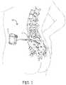
- FIG. 1is a schematic diagram of a neurological lead implanted within a human body or patient.
- FIG. 2A to FIG. 2Care a schematic diagrams of an illustrative method of steering a percutaneous paddle stimulation lead to a target area in a body;
- FIG. 3Ais a schematic diagram top view of an illustrative percutaneous paddle stimulation lead
- FIG. 3Bis a schematic diagram cross-sectional view of the percutaneous paddle stimulation lead of FIG. 3A taken along line 3 B- 3 B;
- FIG. 3Cis a schematic diagram cross-sectional view of another percutaneous paddle stimulation lead embodiment of FIG. 3A taken along line 3 B- 3 B;
- FIG. 4Ais a schematic diagram top view of another illustrative percutaneous paddle stimulation lead
- FIG. 4Bis a schematic diagram cross-sectional view of the percutaneous paddle stimulation lead of FIG. 4A taken along line 4 B- 4 B;
- FIG. 5is a schematic diagram view of another illustrative percutaneous paddle stimulation lead.
- spatially related termsincluding but not limited to, “lower”, “upper”, “beneath”, “below”, “above”, and “on top”, if used herein, are utilized for ease of description to describe spatial relationships of an element(s) to another.
- Such spatially related termsencompass different orientations of the device in use or operation in addition to the particular orientations depicted in the figures and described herein. For example, if a cell depicted in the figures is turned over or flipped over, portions previously described as below or beneath other elements would then be above those other elements.
- an element, component or layer for examplewhen an element, component or layer for example is described as being “on” “connected to”, “coupled with” or “in contact with” another element, component or layer, it can be directly on, directly connected to, directly coupled with, in direct contact with, or intervening elements, components or layers may be on, connected, coupled or in contact with the particular element, component or layer, for example.
- an element, component or layer for exampleis referred to as begin “directly on”, “directly connected to”, “directly coupled with”, or “directly in contact with” another element, there are no intervening elements, components or layers for example.
- the present disclosurerelates to a percutaneous paddle stimulation lead.
- the present disclosurerelates to a percutaneous paddle stimulation lead that can be steered during implantation.
- the percutaneous paddle stimulation leadthat can be steered in a thickness plane of percutaneous paddle stimulation lead during implantation. While the present disclosure is not so limited, an appreciation of various aspects of the disclosure will be gained through a discussion of the examples provided below.
- the teachings presented hereinare applicable to any implantable medical device system employing lead for delivering electrical signals to a tissue of a patient.
- the systemmay include a neurostimulator, such as a peripheral nerve stimulator, a spinal cord stimulator, or a deep brain stimulator; a cardiac pacemaker or defibrillator; a gastric stimulator; or the like.
- a neurostimulatorsuch as a peripheral nerve stimulator, a spinal cord stimulator, or a deep brain stimulator
- a cardiac pacemaker or defibrillatorsuch as a cardiac pacemaker or defibrillator
- a gastric stimulatoror the like.
- FIG. 1shows an environment of an implantable neurological stimulation system 20 .
- the implantable neurological stimulation system 20includes an implantable neurological stimulator 22 , and a stimulation lead 23 .
- the implantable neurological stimulator 22provides a programmable stimulation signal that is delivered to a desired location or target to stimulate selected nerves or muscle tissue.
- the implantable neurological stimulator 22can be implanted in a subcutaneous pocket around the upper buttocks, for example.
- the neurological lead 23is a medical wire with special insulation attached to a planar paddle having a plurality of electrodes (described in more detail below).
- the neurological paddle leads described hereinare designed to be inserted into a patient percutaneously.
- the neurological lead 23can be percutaneously implanted and positioned to stimulate a specific site or area of the patient nervous system.
- the implanted stimulator 22can be any “active medical device” or “signal generator” as described above and can be placed external to or in any location within a body cavity or tissue within the body, or on the surface of a patient's skin, as desired.
- FIG. 2A to FIG. 2Care a schematic diagrams of an illustrative method of steering a percutaneous paddle stimulation lead 70 to a target area 55 in a body 50 .
- FIG. 2Aillustrates schematically a guidewire 60 placed into a body 50 I the direction of the arrow.
- the guidewire 60extends between a distal end 64 and a proximal end 62 .
- the distal end 64is placed in a target area 64 of the body 50 .
- FIG. 2Billustrates schematically sliding a percutaneous paddle stimulation lead 70 along the guidewire 60 until at least a portion of the percutaneous paddle stimulation lead 70 is placed in the target area 55 of the body 50 .
- the percutaneous paddle stimulation lead 70can be formed of materials that provide enough stiffness to the percutaneous paddle stimulation lead 70 so that the percutaneous paddle stimulation lead 70 can be pushed along the guidewire 60 . In other embodiments the percutaneous paddle stimulation lead 70 can be pushed along the guidewire 60 with the assistance of a stylet.
- FIG. 2Cillustrates schematically removing the guidewire 60 from the body 50 .
- the percutaneous paddle stimulation lead 70remains in the target area 55 of the body 50 . Once the guidewire 60 is removed from the body 50 , the percutaneous paddle stimulation lead 70 can be electrically connected to a neurostimulator.
- FIG. 3Ais a schematic diagram top view of an illustrative percutaneous paddle stimulation lead 70 .
- FIG. 3Bis a schematic diagram cross-sectional view of the percutaneous paddle stimulation lead 70 of FIG. 3A taken along line 3 B- 3 B.
- FIG. 3Cis a schematic diagram cross-sectional view of another percutaneous paddle stimulation lead embodiment of FIG. 3A taken along line 3 B- 3 B.
- the embodiment illustrated in FIG. 3Cincludes a second lumen 78 that terminates within the percutaneous paddle stimulation lead 70 includes a lead body 74 .
- the second lumen 78can be configured to receive a stylet (not shown).
- the styletcan be utilized to “push” the percutaneous paddle stimulation lead 70 along the guidewire 60 . Once the percutaneous paddle stimulation lead 70 is placed in the target area, the stylet can be removed from the percutaneous paddle stimulation lead 70 .
- the percutaneous paddle stimulation lead 70includes a lead body 74 defining a paddle structure 72 .
- the paddle structure 72having two opposing major surfaces 73 , 79 .
- the lead body 74extending between a proximal end 76 and a distal end 77 .
- a plurality of electrical contacts 75are disposed on the lead body 74 paddle structure 72 .
- the electrical contacts 75are disposed on only one major surface 73 of the two opposing major surfaces 73 , 79 . While four electrical contacts 75 are illustrated, it is understood that the lead body 74 paddle structure 72 can have any useful number electrical contacts 75 disposed on the lead body 74 paddle structure 72 .
- a lumen 71extends through a length of the lead body 74 from the proximal end 76 to the distal end 77 .
- the lumen 71is configured to receive a guidewire 60 and allow the lead body 74 to move along the guide wire 60 .
- the guidewire 60can be placed and the percutaneous paddle stimulation lead 70 is then loaded onto the guidewire 60 and slid along the guidewire 60 in an “over-the-wire” manner.
- the lead body paddle structure 72has a width W value that is greater than a thickness value T of the lead body paddle structure 72 .
- the lead body paddle structure 72has a width:thickness (W:T) aspect ratio of at least 2:1 or at least 3:1 or at least 4:1 or at least 5:1.
- W:Twidth:thickness
- the lead body 74 and in particular, the paddle structure 72is configured to allow the lead body 74 and in particular, the paddle structure 72 to steer within a thickness plane T defined between the two opposing major surfaces 73 , 79 of the paddle structure 72 .
- the paddle structure 72is configured to allow the lead body 74 and in particular, the paddle structure 72 (having a top surface 73 and an opposing bottom surface 79 ) to steer in a lateral direction (or side surface direction).
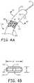
- FIG. 4Ais a schematic diagram top view of another illustrative percutaneous paddle stimulation lead.
- FIG. 4Bis a schematic diagram cross-sectional view of the percutaneous paddle stimulation lead of FIG. 4A taken along line 4 B- 4 B.
- the percutaneous paddle stimulation leadincludes a lead body 174 defining a paddle structure 172 .
- the paddle structure 172having two opposing major surfaces 173 , 179 including a polymeric sheath 150 .
- the lead body 174extending between a proximal end and a distal end.
- a plurality of electrical contacts 175are disposed on the lead body 174 paddle structure 172 .
- the electrical contacts 175are disposed on only one major surface 173 of the two opposing major surfaces 173 , 179 . While three electrical contacts 175 are illustrated, it is understood that the lead body 174 paddle structure 172 can have any useful number electrical contacts 175 disposed on the lead body 174 paddle structure 172 .
- a lumen 171extends through a length of the lead body 174 from the proximal end to the distal end (as described above).
- the lumen 171is configured to receive a guidewire 60 and allow the lead body 174 to move along the guide wire 60 .
- the guidewire 60can be placed and the percutaneous paddle stimulation lead is then loaded onto the guidewire 60 and slid along the guidewire 60 in an “over-the-wire” manner.
- the lead body paddle structure 172has a width W value that is greater than a thickness value T of the lead body paddle structure 172 .
- the lead body paddle structure 172has a width:thickness (W:T) aspect ratio of at least 2:1 or at least 3:1 or at least 4:1 or at least 5:1.
- W:Twidth:thickness
- the lead body 174 and in particular, the paddle structure 172is configured to allow the lead body 174 and in particular, the paddle structure 172 to steer within a thickness plane T defined between the two opposing major surfaces 173 , 179 of the paddle structure 172 .
- the paddle structure 172includes a plurality of fins 120 . Fins disposed along the length of the lead body 174 .
- the fins 120are configured to allow the lead body 174 to steer within a thickness plane T defined between the two opposing major surfaces 173 , 179 of the paddle structure 172 .
- the fins 120are separated by lateral spaces to allow the fins to flex and steer the paddle structure 172 within a thickness plane T defined between the two opposing major surfaces 173 , 179 of the paddle structure 172 .
- FIG. 5is a schematic diagram view of another illustrative percutaneous paddle stimulation lead 200 including paddle structure 272 .
- This embodimentsis similar to the percutaneous paddle stimulation lead shown in FIG. 4A and FIG. 4B except that the lead body 274 is formed of a plurality of stacked segments 220 that are able to move somewhat independently of each other. In many embodiments the plurality of stacked segments 220 are not fixed to one another.
- a polymeric sheath 250is disposed about the plurality of stacked segments 220 .
- a lumen 272is disposed within a notch of each segment 220 and extends along a length of the percutaneous paddle stimulation lead 200 .
- the lumen 272includes a conductor coil assembly that is electrically connected to electrical contacts on the paddle structure as described above.
- the lumen 272can be utilized to receive a guidewire as described above.
- a first steering cable 222 and a second steering cable 224are each extend along a length of the percutaneous paddle stimulation lead 200 and can extend through each of the plurality of stacked segments 220 .
- the lumen 272can be disposed parallel with and between the first steering cable 222 and the second steering cable 224 as illustrated.
- the steering cables 222 , 224are fixed to or near a distal end of the percutaneous paddle stimulation lead 200 .
- the percutaneous paddle stimulation lead 200When the first steering cable 222 is pulled, the percutaneous paddle stimulation lead 200 is deflected in a first direction that can be within a thickness plane defined between the two opposing major surfaces of the paddle structure, as described above.
- the percutaneous paddle stimulation lead 200When the second steering cable 224 is pulled, the percutaneous paddle stimulation lead 200 is deflected in a second direction that can be a direction opposing the first direction and that can be within a thickness plane defined between the two opposing major surfaces of the paddle structure, as described above.
- the first and second steering cables 222 , 224can be utilized in all of the percutaneous paddle stimulation leads described herein either in addition to the guidewire or without the guidewire to steer the percutaneous paddle stimulation leads described herein.
Landscapes
- Health & Medical Sciences (AREA)
- Life Sciences & Earth Sciences (AREA)
- Animal Behavior & Ethology (AREA)
- General Health & Medical Sciences (AREA)
- Nuclear Medicine, Radiotherapy & Molecular Imaging (AREA)
- Engineering & Computer Science (AREA)
- Biomedical Technology (AREA)
- Heart & Thoracic Surgery (AREA)
- Veterinary Medicine (AREA)
- Public Health (AREA)
- Surgery (AREA)
- Pathology (AREA)
- Molecular Biology (AREA)
- Medical Informatics (AREA)
- Neurology (AREA)
- Neurosurgery (AREA)
- Orthopedic Medicine & Surgery (AREA)
- Cardiology (AREA)
- Radiology & Medical Imaging (AREA)
- Electrotherapy Devices (AREA)
Abstract
Description
Claims (17)
Priority Applications (1)
| Application Number | Priority Date | Filing Date | Title |
|---|---|---|---|
| US12/905,456US11045221B2 (en) | 2009-10-30 | 2010-10-15 | Steerable percutaneous paddle stimulation lead |
Applications Claiming Priority (2)
| Application Number | Priority Date | Filing Date | Title |
|---|---|---|---|
| US25637509P | 2009-10-30 | 2009-10-30 | |
| US12/905,456US11045221B2 (en) | 2009-10-30 | 2010-10-15 | Steerable percutaneous paddle stimulation lead |
Publications (2)
| Publication Number | Publication Date |
|---|---|
| US20110106100A1 US20110106100A1 (en) | 2011-05-05 |
| US11045221B2true US11045221B2 (en) | 2021-06-29 |
Family
ID=43926191
Family Applications (1)
| Application Number | Title | Priority Date | Filing Date |
|---|---|---|---|
| US12/905,456Active2035-07-06US11045221B2 (en) | 2009-10-30 | 2010-10-15 | Steerable percutaneous paddle stimulation lead |
Country Status (1)
| Country | Link |
|---|---|
| US (1) | US11045221B2 (en) |
Families Citing this family (35)
| Publication number | Priority date | Publication date | Assignee | Title |
|---|---|---|---|---|
| US9561053B2 (en) | 2007-04-25 | 2017-02-07 | Medtronic, Inc. | Implant tool to facilitate medical device implantation |
| US9399130B2 (en) | 2007-04-25 | 2016-07-26 | Medtronic, Inc. | Cannula configured to deliver test stimulation |
| ES2528474T3 (en)* | 2011-02-16 | 2015-02-10 | Boston Scientific Neuromodulation Corporation | Systems and methods for implanting sets of shovel conductors of electrical stimulation systems |
| CN103648583B (en) | 2011-05-13 | 2016-01-20 | 萨鲁达医疗有限公司 | For measuring method and the instrument of nerves reaction-A |
| WO2012155185A1 (en) | 2011-05-13 | 2012-11-22 | National Ict Australia Ltd | Method and apparatus for measurement of neural response |
| US10588524B2 (en) | 2011-05-13 | 2020-03-17 | Saluda Medical Pty Ltd | Method and apparatus for measurement of neural response |
| WO2012155189A1 (en) | 2011-05-13 | 2012-11-22 | National Ict Australia Ltd | Method and apparatus for estimating neural recruitment - f |
| US9872990B2 (en) | 2011-05-13 | 2018-01-23 | Saluda Medical Pty Limited | Method and apparatus for application of a neural stimulus |
| WO2013075171A1 (en)* | 2011-11-24 | 2013-05-30 | National Ict Australia Ltd | Electrode assembly for an active implantable medical device |
| US10206596B2 (en) | 2012-11-06 | 2019-02-19 | Saluda Medical Pty Ltd | Method and system for controlling electrical conditions of tissue |
| EP2908905B1 (en) | 2012-11-06 | 2020-09-23 | Saluda Medical Pty Limited | System for controlling electrical conditions of tissue |
| US9308022B2 (en) | 2012-12-10 | 2016-04-12 | Nevro Corporation | Lead insertion devices and associated systems and methods |
| JP6730185B2 (en) | 2013-11-15 | 2020-07-29 | サルーダ・メディカル・ピーティーワイ・リミテッド | Cerebral nerve potential monitoring |
| CA2929874C (en) | 2013-11-22 | 2023-06-13 | Saluda Medical Pty Ltd | Method and device for detecting a neural response in a neural measurement |
| EP3122247B1 (en) | 2014-03-28 | 2025-05-07 | Saluda Medical Pty Ltd | Assessing neural state from action potentials |
| ES2801348T3 (en) | 2014-05-05 | 2021-01-11 | Saluda Medical Pty Ltd | Improved neurological measurement |
| WO2016011512A1 (en) | 2014-07-25 | 2016-01-28 | Saluda Medical Pty Ltd | Neural stimulation dosing |
| US9643003B2 (en) | 2014-11-10 | 2017-05-09 | Steven Sounyoung Yu | Craniofacial neurostimulation for treatment of pain conditions |
| AU2015349614B2 (en) | 2014-11-17 | 2020-10-22 | Saluda Medical Pty Ltd | Method and device for detecting a neural response in neural measurements |
| WO2016090436A1 (en) | 2014-12-11 | 2016-06-16 | Saluda Medical Pty Ltd | Method and device for feedback control of neural stimulation |
| EP3229890B1 (en) | 2014-12-11 | 2020-05-27 | Saluda Medical Pty Limited | Implantable electrode positioning |
| US10918872B2 (en) | 2015-01-19 | 2021-02-16 | Saluda Medical Pty Ltd | Method and device for neural implant communication |
| US9789321B2 (en) | 2015-04-03 | 2017-10-17 | Nevro Corp. | Couplings for implanted leads and external stimulators, and associated systems and methods |
| US10894158B2 (en) | 2015-04-09 | 2021-01-19 | Saluda Medical Pty Ltd | Electrode to nerve distance estimation |
| CN107614055B (en) | 2015-05-31 | 2022-02-25 | 闭环医疗私人有限公司 | Brain nerve stimulator electrode assembly |
| WO2016191808A1 (en) | 2015-05-31 | 2016-12-08 | Saluda Medical Pty Ltd | Monitoring brain neural activity |
| WO2016191815A1 (en) | 2015-06-01 | 2016-12-08 | Saluda Medical Pty Ltd | Motor fibre neuromodulation |
| US10328271B2 (en) | 2015-11-12 | 2019-06-25 | Medtronic, Inc. | Implantable electrical stimulator with deflecting tip lead |
| ES2888773T3 (en) | 2016-04-05 | 2022-01-07 | Saluda Medical Pty Ltd | Improved neuromodulation feedback control |
| EP3474747A4 (en) | 2016-06-24 | 2020-01-22 | Saluda Medical Pty Ltd | NERVOUS STIMULATION FOR REDUCED ARTIFACT |
| US10980999B2 (en) | 2017-03-09 | 2021-04-20 | Nevro Corp. | Paddle leads and delivery tools, and associated systems and methods |
| DE102017216424B4 (en)* | 2017-09-15 | 2025-07-10 | AdjuCor GmbH | Lead system for a medical implant |
| WO2019191423A1 (en) | 2018-03-29 | 2019-10-03 | Nevro Corp. | Leads having sidewall openings, and associated systems and methods |
| EP4434461A3 (en) | 2018-04-27 | 2025-03-05 | Saluda Medical Pty Ltd | Neurostimulation of mixed nerves |
| US20240238587A1 (en)* | 2021-05-06 | 2024-07-18 | Foresite Capital Holdings, Llc | Implantable medical lead and related devices and methods |
Citations (88)
| Publication number | Priority date | Publication date | Assignee | Title |
|---|---|---|---|---|
| US4332259A (en)* | 1979-09-19 | 1982-06-01 | Mccorkle Jr Charles E | Intravenous channel cardiac electrode and lead assembly and method |
| US4920980A (en) | 1987-09-14 | 1990-05-01 | Cordis Corporation | Catheter with controllable tip |
| US4991603A (en)* | 1989-10-30 | 1991-02-12 | Siemens-Pacesetter, Inc. | Transvenously placed defibrillation leads via an inferior vena cava access site and method of use |
| US5195968A (en)* | 1990-02-02 | 1993-03-23 | Ingemar Lundquist | Catheter steering mechanism |
| US5279299A (en)* | 1991-02-15 | 1994-01-18 | Cardiac Pathways Corporation | Endocardial mapping and ablation system and catheter probe |
| US5396902A (en)* | 1993-02-03 | 1995-03-14 | Medtronic, Inc. | Steerable stylet and manipulative handle assembly |
| US5501703A (en) | 1994-01-24 | 1996-03-26 | Medtronic, Inc. | Multichannel apparatus for epidural spinal cord stimulator |
| US5505201A (en)* | 1994-04-20 | 1996-04-09 | Case Western Reserve University | Implantable helical spiral cuff electrode |
| US5575814A (en)* | 1995-01-27 | 1996-11-19 | Medtronic, Inc. | Active fixation medical electrical lead having mapping capability |
| US5676653A (en)* | 1995-06-27 | 1997-10-14 | Arrow International Investment Corp. | Kink-resistant steerable catheter assembly |
| US5733322A (en)* | 1995-05-23 | 1998-03-31 | Medtronic, Inc. | Positive fixation percutaneous epidural neurostimulation lead |
| US5800482A (en)* | 1996-03-06 | 1998-09-01 | Cardiac Pathways Corporation | Apparatus and method for linear lesion ablation |
| US5895416A (en)* | 1997-03-12 | 1999-04-20 | Medtronic, Inc. | Method and apparatus for controlling and steering an electric field |
| US5954761A (en)* | 1997-03-25 | 1999-09-21 | Intermedics Inc. | Implantable endocardial lead assembly having a stent |
| US5967977A (en)* | 1997-10-03 | 1999-10-19 | Medtronic, Inc. | Transesophageal medical lead |
| US6038480A (en) | 1996-04-04 | 2000-03-14 | Medtronic, Inc. | Living tissue stimulation and recording techniques with local control of active sites |
| US6106522A (en)* | 1993-10-14 | 2000-08-22 | Ep Technologies, Inc. | Systems and methods for forming elongated lesion patterns in body tissue using straight or curvilinear electrode elements |
| US6112124A (en)* | 1996-01-24 | 2000-08-29 | Advanced Bionics Corporation | Cochlear electrode array employing dielectric members |
| US6192280B1 (en)* | 1999-06-02 | 2001-02-20 | Medtronic, Inc. | Guidewire placed implantable lead with tip seal |
| US6205361B1 (en)* | 1998-02-10 | 2001-03-20 | Advanced Bionics Corporation | Implantable expandable multicontact electrodes |
| US6216045B1 (en)* | 1999-04-26 | 2001-04-10 | Advanced Neuromodulation Systems, Inc. | Implantable lead and method of manufacture |
| US6236892B1 (en)* | 1999-10-07 | 2001-05-22 | Claudio A. Feler | Spinal cord stimulation lead |
| US6249707B1 (en)* | 1999-04-30 | 2001-06-19 | Medtronic, Inc. | Apparatus and method for percutaneous implant of a paddle style lead |
| US20010018607A1 (en)* | 1999-03-18 | 2001-08-30 | Medtronic, Inc. | Co-extruded, multi-lumen medical lead |
| US20010025192A1 (en)* | 1999-04-29 | 2001-09-27 | Medtronic, Inc. | Single and multi-polar implantable lead for sacral nerve electrical stimulation |
| US6319241B1 (en)* | 1998-04-30 | 2001-11-20 | Medtronic, Inc. | Techniques for positioning therapy delivery elements within a spinal cord or a brain |
| US20020022873A1 (en)* | 2000-08-10 | 2002-02-21 | Erickson John H. | Stimulation/sensing lead adapted for percutaneous insertion |
| US6374143B1 (en)* | 1999-08-18 | 2002-04-16 | Epic Biosonics, Inc. | Modiolar hugging electrode array |
| US20020065544A1 (en)* | 1999-11-29 | 2002-05-30 | Medtronic, Inc. | Medical electrical lead having variable bending stiffness |
| US6415187B1 (en)* | 1998-02-10 | 2002-07-02 | Advanced Bionics Corporation | Implantable, expandable, multicontact electrodes and insertion needle for use therewith |
| US6447506B1 (en)* | 1993-10-15 | 2002-09-10 | Ep Technologies, Inc. | Systems and methods for creating long, thin lesions in body tissue |
| US20020128700A1 (en)* | 2001-03-08 | 2002-09-12 | Cross Thomas E. | Lead with adjustable angular and spatial relationships between electrodes |
| US20020173785A1 (en)* | 2000-03-31 | 2002-11-21 | Medtronic, Inc. | System and method for positioning implantable medical devices within coronary veins |
| US20030009095A1 (en)* | 2001-05-21 | 2003-01-09 | Skarda James R. | Malleable elongated medical device |
| US6512958B1 (en)* | 2001-04-26 | 2003-01-28 | Medtronic, Inc. | Percutaneous medical probe and flexible guide wire |
| US20030028147A1 (en)* | 2001-08-02 | 2003-02-06 | Teodulo Aves | Medical needle |
| US6522932B1 (en)* | 1998-02-10 | 2003-02-18 | Advanced Bionics Corporation | Implantable, expandable, multicontact electrodes and tools for use therewith |
| US6587733B1 (en) | 2000-02-08 | 2003-07-01 | Medtronic, Inc. | Percutaneous surgical lead body with directed stimulation |
| US20030163171A1 (en)* | 2002-02-28 | 2003-08-28 | Kast John E. | In-line lead header for an implantable medical device |
| US20030204228A1 (en)* | 2002-04-25 | 2003-10-30 | Cross Thomas E. | Surgical lead paddle |
| US20030220677A1 (en)* | 2002-05-22 | 2003-11-27 | Doan Phong D. | Implantable coronary sinus lead and lead system |
| US20040059404A1 (en)* | 2002-09-24 | 2004-03-25 | Bjorklund Vicki L. | Deployable medical lead fixation system and method |
| US6721604B1 (en) | 2000-07-27 | 2004-04-13 | Micronet Medical, Inc. | Reduced diameter, low resistance medical electrical lead |
| US20040230268A1 (en)* | 2003-05-13 | 2004-11-18 | Medtronic, Inc. | Medical lead adaptor assembly |
| US20040236397A1 (en)* | 1999-04-05 | 2004-11-25 | The Spectranetics Corporation | Lead locking device and method |
| US20040260310A1 (en)* | 2002-10-23 | 2004-12-23 | Medtronic, Inc. | Medical lead and method |
| US6847849B2 (en)* | 2000-11-15 | 2005-01-25 | Medtronic, Inc. | Minimally invasive apparatus for implanting a sacral stimulation lead |
| US20050027338A1 (en)* | 2003-07-29 | 2005-02-03 | Advanced Neuromodulation Systems, Inc. | Stretchable lead body, method of manufacture, and system |
| US20050033393A1 (en)* | 2003-08-08 | 2005-02-10 | Advanced Neuromodulation Systems, Inc. | Apparatus and method for implanting an electrical stimulation system and a paddle style electrical stimulation lead |
| US20050049664A1 (en)* | 2003-08-29 | 2005-03-03 | Harris Charmaine K. | Percutaneous flat lead introducer |
| US20050090885A1 (en)* | 2003-10-23 | 2005-04-28 | Medtronic, Inc. | Medical lead and manufacturing method therefor |
| US6909918B2 (en)* | 2001-10-10 | 2005-06-21 | Medtronic, Inc. | Implantable percutaneous stimulation lead with lead carrier |
| US20050182470A1 (en)* | 2002-10-23 | 2005-08-18 | Medtronic, Inc. | Paddle-style medical lead and method |
| US20050203600A1 (en)* | 2004-03-12 | 2005-09-15 | Scimed Life Systems, Inc. | Collapsible/expandable tubular electrode leads |
| US20050203599A1 (en)* | 2004-03-12 | 2005-09-15 | Scimed Life Systems, Inc. | Modular stimulation lead network |
| US20050222658A1 (en)* | 2004-03-30 | 2005-10-06 | Medtronic, Inc. | Lead electrode for use in an MRI-safe implantable medical device |
| US20050288759A1 (en)* | 2003-08-08 | 2005-12-29 | Jones Timothy S | Method and apparatus for implanting an electrical stimulation lead using a flexible introducer |
| US20060089691A1 (en)* | 2004-10-21 | 2006-04-27 | Medtronic, Inc. | Implantable medical lead with axially oriented coiled wire conductors |
| US7047082B1 (en) | 1999-09-16 | 2006-05-16 | Micronet Medical, Inc. | Neurostimulating lead |
| US7063682B1 (en)* | 1996-12-19 | 2006-06-20 | Ep Technologies, Inc. | Catheter distal assembly with pull wires |
| US7072719B2 (en)* | 2001-09-20 | 2006-07-04 | Medtronic, Inc. | Implantable percutaneous stimulation lead with interlocking elements |
| US7082335B2 (en)* | 2002-09-30 | 2006-07-25 | Medtronic, Inc. | Multipolar pacing method and apparatus |
| US7146224B2 (en) | 2005-01-19 | 2006-12-05 | Medtronic, Inc. | Apparatus for multiple site stimulation |
| US20070027514A1 (en)* | 2005-07-29 | 2007-02-01 | Medtronic, Inc. | Electrical stimulation lead with conformable array of electrodes |
| US20070038279A1 (en)* | 2005-08-15 | 2007-02-15 | Fifer Daniel W | Electrodes for implantable medical devices |
| US7184838B2 (en)* | 2003-10-02 | 2007-02-27 | Medtronic, Inc. | Implantable medical lead and method of manufacture |
| US20070049846A1 (en)* | 2005-08-24 | 2007-03-01 | C.R.Bard, Inc. | Stylet Apparatuses and Methods of Manufacture |
| US20070078455A1 (en)* | 1997-06-20 | 2007-04-05 | Rassoll Rashidi | Electrophysiology/ablation catheter and remote actuator therefor |
| US20070135803A1 (en)* | 2005-09-14 | 2007-06-14 | Amir Belson | Methods and apparatus for performing transluminal and other procedures |
| US7238883B2 (en)* | 2004-08-11 | 2007-07-03 | Cardiac Pacemakers, Inc. | Lead assembly with flexible portions and method therefor |
| US7241180B1 (en)* | 2006-01-31 | 2007-07-10 | Medtronic, Inc. | Medical electrical lead connector assembly |
| US20070179579A1 (en)* | 2006-01-26 | 2007-08-02 | Feler Claudio A | Method of neurostimulation of distinct neural structures using single paddle lead to treat multiple pain locations and multi-column, multi-row paddle lead for such neurostimulation |
| EP1818074A1 (en) | 2006-02-10 | 2007-08-15 | Advanced Neuromodulation Systems, Inc. | Self-folding paddle lead and method of fabricating a paddle lead |
| US20070213795A1 (en)* | 2003-05-08 | 2007-09-13 | Kerry Bradley | Implantable medical lead |
| US20080140169A1 (en)* | 2006-12-06 | 2008-06-12 | Spinal Modulation, Inc. | Delivery devices, systems and methods for stimulating nerve tissue on multiple spinal levels |
| US20080147158A1 (en)* | 2006-12-18 | 2008-06-19 | Quan Emerteq Corp. | Implantable Medical Lead Having Coil Electrode |
| US7396335B2 (en) | 2000-09-12 | 2008-07-08 | Medtronic, Inc. | Method and apparatus for deflecting a screw-in lead |
| WO2008085528A1 (en) | 2007-01-12 | 2008-07-17 | Medtronic, Inc. | Expandable systems for medical electrical stimulation |
| US7496410B2 (en)* | 2005-01-10 | 2009-02-24 | Cardiac Pacemakers, Inc. | Spring fixation mechanism for epicardial leads |
| US20090187221A1 (en)* | 2008-01-23 | 2009-07-23 | Andrew Digiore | Paddle lead configurations for electrical stimulation systems and methods of making and using |
| US20090270960A1 (en)* | 2008-04-29 | 2009-10-29 | Weiying Zhao | Systems and methods for delivering electric current for spinal cord stimulation |
| US20100179540A1 (en)* | 2006-10-06 | 2010-07-15 | Stanislaw Marczyk | Endoscopic Vessel Sealer and Divider Having a Flexible Articulating Shaft |
| US7761985B2 (en)* | 2005-01-31 | 2010-07-27 | Medtronic, Inc. | Method of manufacturing a medical lead |
| US7894913B2 (en)* | 2004-06-10 | 2011-02-22 | Medtronic Urinary Solutions, Inc. | Systems and methods of neuromodulation stimulation for the restoration of sexual function |
| US7925352B2 (en)* | 2008-03-27 | 2011-04-12 | Synecor Llc | System and method for transvascularly stimulating contents of the carotid sheath |
| US7949412B1 (en)* | 2005-06-02 | 2011-05-24 | Advanced Bionics, Llc | Coated electrode array having uncoated electrode contacts |
| US8147486B2 (en)* | 2003-09-22 | 2012-04-03 | St. Jude Medical, Atrial Fibrillation Division, Inc. | Medical device with flexible printed circuit |
| US8380325B2 (en)* | 2009-08-05 | 2013-02-19 | Boston Scientific Neuromodulation Corporation | Systems and methods for coupling coiled conductors to conductive contacts of an electrical stimulation system |
- 2010
- 2010-10-15USUS12/905,456patent/US11045221B2/enactiveActive
Patent Citations (102)
| Publication number | Priority date | Publication date | Assignee | Title |
|---|---|---|---|---|
| US4332259A (en)* | 1979-09-19 | 1982-06-01 | Mccorkle Jr Charles E | Intravenous channel cardiac electrode and lead assembly and method |
| US4920980A (en) | 1987-09-14 | 1990-05-01 | Cordis Corporation | Catheter with controllable tip |
| US4991603A (en)* | 1989-10-30 | 1991-02-12 | Siemens-Pacesetter, Inc. | Transvenously placed defibrillation leads via an inferior vena cava access site and method of use |
| US5195968A (en)* | 1990-02-02 | 1993-03-23 | Ingemar Lundquist | Catheter steering mechanism |
| US5279299A (en)* | 1991-02-15 | 1994-01-18 | Cardiac Pathways Corporation | Endocardial mapping and ablation system and catheter probe |
| US5396902A (en)* | 1993-02-03 | 1995-03-14 | Medtronic, Inc. | Steerable stylet and manipulative handle assembly |
| US6106522A (en)* | 1993-10-14 | 2000-08-22 | Ep Technologies, Inc. | Systems and methods for forming elongated lesion patterns in body tissue using straight or curvilinear electrode elements |
| US6447506B1 (en)* | 1993-10-15 | 2002-09-10 | Ep Technologies, Inc. | Systems and methods for creating long, thin lesions in body tissue |
| US5501703A (en) | 1994-01-24 | 1996-03-26 | Medtronic, Inc. | Multichannel apparatus for epidural spinal cord stimulator |
| US5643330A (en) | 1994-01-24 | 1997-07-01 | Medtronic, Inc. | Multichannel apparatus for epidural spinal cord stimulation |
| US5505201A (en)* | 1994-04-20 | 1996-04-09 | Case Western Reserve University | Implantable helical spiral cuff electrode |
| US5575814A (en)* | 1995-01-27 | 1996-11-19 | Medtronic, Inc. | Active fixation medical electrical lead having mapping capability |
| US5733322A (en)* | 1995-05-23 | 1998-03-31 | Medtronic, Inc. | Positive fixation percutaneous epidural neurostimulation lead |
| US5676653A (en)* | 1995-06-27 | 1997-10-14 | Arrow International Investment Corp. | Kink-resistant steerable catheter assembly |
| US6112124A (en)* | 1996-01-24 | 2000-08-29 | Advanced Bionics Corporation | Cochlear electrode array employing dielectric members |
| US5800482A (en)* | 1996-03-06 | 1998-09-01 | Cardiac Pathways Corporation | Apparatus and method for linear lesion ablation |
| US6038480A (en) | 1996-04-04 | 2000-03-14 | Medtronic, Inc. | Living tissue stimulation and recording techniques with local control of active sites |
| US7063682B1 (en)* | 1996-12-19 | 2006-06-20 | Ep Technologies, Inc. | Catheter distal assembly with pull wires |
| US5895416A (en)* | 1997-03-12 | 1999-04-20 | Medtronic, Inc. | Method and apparatus for controlling and steering an electric field |
| US5954761A (en)* | 1997-03-25 | 1999-09-21 | Intermedics Inc. | Implantable endocardial lead assembly having a stent |
| US20070078455A1 (en)* | 1997-06-20 | 2007-04-05 | Rassoll Rashidi | Electrophysiology/ablation catheter and remote actuator therefor |
| US7881809B2 (en)* | 1997-06-20 | 2011-02-01 | St. Jude Medical, Atrial Fibrillation Division, Inc. | Electrophysiology/ablation catheter and remote actuator therefor |
| US5967977A (en)* | 1997-10-03 | 1999-10-19 | Medtronic, Inc. | Transesophageal medical lead |
| US6205361B1 (en)* | 1998-02-10 | 2001-03-20 | Advanced Bionics Corporation | Implantable expandable multicontact electrodes |
| US6415187B1 (en)* | 1998-02-10 | 2002-07-02 | Advanced Bionics Corporation | Implantable, expandable, multicontact electrodes and insertion needle for use therewith |
| US6522932B1 (en)* | 1998-02-10 | 2003-02-18 | Advanced Bionics Corporation | Implantable, expandable, multicontact electrodes and tools for use therewith |
| US7191018B2 (en)* | 1998-04-30 | 2007-03-13 | Medtronic, Inc. | Techniques for positioning therapy delivery elements within a spinal cord or brain |
| US6319241B1 (en)* | 1998-04-30 | 2001-11-20 | Medtronic, Inc. | Techniques for positioning therapy delivery elements within a spinal cord or a brain |
| US20010018607A1 (en)* | 1999-03-18 | 2001-08-30 | Medtronic, Inc. | Co-extruded, multi-lumen medical lead |
| US8428747B2 (en)* | 1999-04-05 | 2013-04-23 | The Spectranetics Corp. | Lead locking device and method |
| US20040236397A1 (en)* | 1999-04-05 | 2004-11-25 | The Spectranetics Corporation | Lead locking device and method |
| US6216045B1 (en)* | 1999-04-26 | 2001-04-10 | Advanced Neuromodulation Systems, Inc. | Implantable lead and method of manufacture |
| US20080188917A1 (en)* | 1999-04-29 | 2008-08-07 | Medtronic, Inc. | Single and multipolar implantable lead for sacral nerve electrical stimulation |
| US20010025192A1 (en)* | 1999-04-29 | 2001-09-27 | Medtronic, Inc. | Single and multi-polar implantable lead for sacral nerve electrical stimulation |
| US6249707B1 (en)* | 1999-04-30 | 2001-06-19 | Medtronic, Inc. | Apparatus and method for percutaneous implant of a paddle style lead |
| US6192280B1 (en)* | 1999-06-02 | 2001-02-20 | Medtronic, Inc. | Guidewire placed implantable lead with tip seal |
| US6374143B1 (en)* | 1999-08-18 | 2002-04-16 | Epic Biosonics, Inc. | Modiolar hugging electrode array |
| US7047082B1 (en) | 1999-09-16 | 2006-05-16 | Micronet Medical, Inc. | Neurostimulating lead |
| US6236892B1 (en)* | 1999-10-07 | 2001-05-22 | Claudio A. Feler | Spinal cord stimulation lead |
| US20020065544A1 (en)* | 1999-11-29 | 2002-05-30 | Medtronic, Inc. | Medical electrical lead having variable bending stiffness |
| US7319904B2 (en) | 2000-02-08 | 2008-01-15 | Medtronic, Inc. | Percutaneous Surgical lead body |
| US6587733B1 (en) | 2000-02-08 | 2003-07-01 | Medtronic, Inc. | Percutaneous surgical lead body with directed stimulation |
| US7497844B2 (en) | 2000-03-31 | 2009-03-03 | Medtronic, Inc. | System and method for positioning implantable medical devices within coronary veins |
| US20020173785A1 (en)* | 2000-03-31 | 2002-11-21 | Medtronic, Inc. | System and method for positioning implantable medical devices within coronary veins |
| US6721604B1 (en) | 2000-07-27 | 2004-04-13 | Micronet Medical, Inc. | Reduced diameter, low resistance medical electrical lead |
| US6895283B2 (en)* | 2000-08-10 | 2005-05-17 | Advanced Neuromodulation Systems, Inc. | Stimulation/sensing lead adapted for percutaneous insertion |
| US20020022873A1 (en)* | 2000-08-10 | 2002-02-21 | Erickson John H. | Stimulation/sensing lead adapted for percutaneous insertion |
| US7396335B2 (en) | 2000-09-12 | 2008-07-08 | Medtronic, Inc. | Method and apparatus for deflecting a screw-in lead |
| US6847849B2 (en)* | 2000-11-15 | 2005-01-25 | Medtronic, Inc. | Minimally invasive apparatus for implanting a sacral stimulation lead |
| US20020128700A1 (en)* | 2001-03-08 | 2002-09-12 | Cross Thomas E. | Lead with adjustable angular and spatial relationships between electrodes |
| US6512958B1 (en)* | 2001-04-26 | 2003-01-28 | Medtronic, Inc. | Percutaneous medical probe and flexible guide wire |
| US20030009095A1 (en)* | 2001-05-21 | 2003-01-09 | Skarda James R. | Malleable elongated medical device |
| US20030028147A1 (en)* | 2001-08-02 | 2003-02-06 | Teodulo Aves | Medical needle |
| US7072719B2 (en)* | 2001-09-20 | 2006-07-04 | Medtronic, Inc. | Implantable percutaneous stimulation lead with interlocking elements |
| US6909918B2 (en)* | 2001-10-10 | 2005-06-21 | Medtronic, Inc. | Implantable percutaneous stimulation lead with lead carrier |
| US6895276B2 (en)* | 2002-02-28 | 2005-05-17 | Medtronic, Inc. | In-line lead header for an implantable medical device |
| US20030163171A1 (en)* | 2002-02-28 | 2003-08-28 | Kast John E. | In-line lead header for an implantable medical device |
| US20030204228A1 (en)* | 2002-04-25 | 2003-10-30 | Cross Thomas E. | Surgical lead paddle |
| US20030220677A1 (en)* | 2002-05-22 | 2003-11-27 | Doan Phong D. | Implantable coronary sinus lead and lead system |
| US20040059404A1 (en)* | 2002-09-24 | 2004-03-25 | Bjorklund Vicki L. | Deployable medical lead fixation system and method |
| US7082335B2 (en)* | 2002-09-30 | 2006-07-25 | Medtronic, Inc. | Multipolar pacing method and apparatus |
| US7499755B2 (en) | 2002-10-23 | 2009-03-03 | Medtronic, Inc. | Paddle-style medical lead and method |
| US20040260310A1 (en)* | 2002-10-23 | 2004-12-23 | Medtronic, Inc. | Medical lead and method |
| US20050182470A1 (en)* | 2002-10-23 | 2005-08-18 | Medtronic, Inc. | Paddle-style medical lead and method |
| US20070213795A1 (en)* | 2003-05-08 | 2007-09-13 | Kerry Bradley | Implantable medical lead |
| US20040230268A1 (en)* | 2003-05-13 | 2004-11-18 | Medtronic, Inc. | Medical lead adaptor assembly |
| US20050027338A1 (en)* | 2003-07-29 | 2005-02-03 | Advanced Neuromodulation Systems, Inc. | Stretchable lead body, method of manufacture, and system |
| US20050288759A1 (en)* | 2003-08-08 | 2005-12-29 | Jones Timothy S | Method and apparatus for implanting an electrical stimulation lead using a flexible introducer |
| US7359755B2 (en)* | 2003-08-08 | 2008-04-15 | Advanced Neuromodulation Systems, Inc. | Method and apparatus for implanting an electrical stimulation lead using a flexible introducer |
| US20050033393A1 (en)* | 2003-08-08 | 2005-02-10 | Advanced Neuromodulation Systems, Inc. | Apparatus and method for implanting an electrical stimulation system and a paddle style electrical stimulation lead |
| US20050049664A1 (en)* | 2003-08-29 | 2005-03-03 | Harris Charmaine K. | Percutaneous flat lead introducer |
| US8147486B2 (en)* | 2003-09-22 | 2012-04-03 | St. Jude Medical, Atrial Fibrillation Division, Inc. | Medical device with flexible printed circuit |
| US7184838B2 (en)* | 2003-10-02 | 2007-02-27 | Medtronic, Inc. | Implantable medical lead and method of manufacture |
| US7437197B2 (en)* | 2003-10-23 | 2008-10-14 | Medtronic, Inc. | Medical lead and manufacturing method therefor |
| US20050090885A1 (en)* | 2003-10-23 | 2005-04-28 | Medtronic, Inc. | Medical lead and manufacturing method therefor |
| US20050203600A1 (en)* | 2004-03-12 | 2005-09-15 | Scimed Life Systems, Inc. | Collapsible/expandable tubular electrode leads |
| US20050203599A1 (en)* | 2004-03-12 | 2005-09-15 | Scimed Life Systems, Inc. | Modular stimulation lead network |
| US20050222658A1 (en)* | 2004-03-30 | 2005-10-06 | Medtronic, Inc. | Lead electrode for use in an MRI-safe implantable medical device |
| US7894913B2 (en)* | 2004-06-10 | 2011-02-22 | Medtronic Urinary Solutions, Inc. | Systems and methods of neuromodulation stimulation for the restoration of sexual function |
| US7238883B2 (en)* | 2004-08-11 | 2007-07-03 | Cardiac Pacemakers, Inc. | Lead assembly with flexible portions and method therefor |
| US20060089691A1 (en)* | 2004-10-21 | 2006-04-27 | Medtronic, Inc. | Implantable medical lead with axially oriented coiled wire conductors |
| US7496410B2 (en)* | 2005-01-10 | 2009-02-24 | Cardiac Pacemakers, Inc. | Spring fixation mechanism for epicardial leads |
| US7146224B2 (en) | 2005-01-19 | 2006-12-05 | Medtronic, Inc. | Apparatus for multiple site stimulation |
| US7761985B2 (en)* | 2005-01-31 | 2010-07-27 | Medtronic, Inc. | Method of manufacturing a medical lead |
| US7949412B1 (en)* | 2005-06-02 | 2011-05-24 | Advanced Bionics, Llc | Coated electrode array having uncoated electrode contacts |
| US20070027514A1 (en)* | 2005-07-29 | 2007-02-01 | Medtronic, Inc. | Electrical stimulation lead with conformable array of electrodes |
| US20070038279A1 (en)* | 2005-08-15 | 2007-02-15 | Fifer Daniel W | Electrodes for implantable medical devices |
| US20070049846A1 (en)* | 2005-08-24 | 2007-03-01 | C.R.Bard, Inc. | Stylet Apparatuses and Methods of Manufacture |
| US8784336B2 (en)* | 2005-08-24 | 2014-07-22 | C. R. Bard, Inc. | Stylet apparatuses and methods of manufacture |
| US20070135803A1 (en)* | 2005-09-14 | 2007-06-14 | Amir Belson | Methods and apparatus for performing transluminal and other procedures |
| US20070179579A1 (en)* | 2006-01-26 | 2007-08-02 | Feler Claudio A | Method of neurostimulation of distinct neural structures using single paddle lead to treat multiple pain locations and multi-column, multi-row paddle lead for such neurostimulation |
| US7241180B1 (en)* | 2006-01-31 | 2007-07-10 | Medtronic, Inc. | Medical electrical lead connector assembly |
| US20070191709A1 (en)* | 2006-02-10 | 2007-08-16 | Swanson John W | Self-folding paddle lead and method of fabricating a paddle lead |
| EP1818074A1 (en) | 2006-02-10 | 2007-08-15 | Advanced Neuromodulation Systems, Inc. | Self-folding paddle lead and method of fabricating a paddle lead |
| US20100179540A1 (en)* | 2006-10-06 | 2010-07-15 | Stanislaw Marczyk | Endoscopic Vessel Sealer and Divider Having a Flexible Articulating Shaft |
| US20080140169A1 (en)* | 2006-12-06 | 2008-06-12 | Spinal Modulation, Inc. | Delivery devices, systems and methods for stimulating nerve tissue on multiple spinal levels |
| US20080147158A1 (en)* | 2006-12-18 | 2008-06-19 | Quan Emerteq Corp. | Implantable Medical Lead Having Coil Electrode |
| WO2008085528A1 (en) | 2007-01-12 | 2008-07-17 | Medtronic, Inc. | Expandable systems for medical electrical stimulation |
| US20090187221A1 (en)* | 2008-01-23 | 2009-07-23 | Andrew Digiore | Paddle lead configurations for electrical stimulation systems and methods of making and using |
| US7925352B2 (en)* | 2008-03-27 | 2011-04-12 | Synecor Llc | System and method for transvascularly stimulating contents of the carotid sheath |
| US20090270960A1 (en)* | 2008-04-29 | 2009-10-29 | Weiying Zhao | Systems and methods for delivering electric current for spinal cord stimulation |
| US8380325B2 (en)* | 2009-08-05 | 2013-02-19 | Boston Scientific Neuromodulation Corporation | Systems and methods for coupling coiled conductors to conductive contacts of an electrical stimulation system |
Non-Patent Citations (4)
| Title |
|---|
| Claeys, L., "Spinal Cord Stimulation and Chronic Critical Limb Ischemia", Neuromodulation, 1999, vol. 2, No. 1. |
| Hoisheimer, J., et al., "Clinical Evaluation of Paresthesia Steering with a New System for Spinal Cord Stimulation", Neurosurgery, 1998, No. 3, pp. 541-547. |
| Holsheimer, J., et al., "Effect of Anode-Chaode Configuration on Paresthesia Coverage in Spinal Cord Stimulation", Neurosurgery, Sep. 1997, pp. 654-659. |
| Slavin, K.V., et al., "Efficacy of Transverse Tripolar Stimulation for Relief of Chronic Low Back Pain", Stereotactic and Functional Neurosurgery, 1999, pp. 126-130, vol. 73. |
Also Published As
| Publication number | Publication date |
|---|---|
| US20110106100A1 (en) | 2011-05-05 |
Similar Documents
| Publication | Publication Date | Title |
|---|---|---|
| US11045221B2 (en) | Steerable percutaneous paddle stimulation lead | |
| US8738153B2 (en) | Implantable lead with braided conductors | |
| US9757555B2 (en) | Pre-molded sub-assemblies for implantable medical leads | |
| US20210085959A1 (en) | Self-tunneling lead | |
| US8606367B2 (en) | Insertion tool for paddle-style electrode | |
| US8112159B2 (en) | Kit for implantation of therapy elements | |
| US7072719B2 (en) | Implantable percutaneous stimulation lead with interlocking elements | |
| US6909918B2 (en) | Implantable percutaneous stimulation lead with lead carrier | |
| US10391304B2 (en) | Neurostimulation lead with stiffened proximal array | |
| EP2252365B1 (en) | Temporary neurostimulation lead identification device | |
| US8805544B2 (en) | Insertion tool for paddle-style electrode | |
| US20120016377A1 (en) | Tunneling tool for implantable leads | |
| US20110029055A1 (en) | Spiral lead | |
| US9144673B2 (en) | Self anchoring lead | |
| US20140018885A1 (en) | Systems and methods for making and using an electrical stimulation system with a tissue-penetrating electrode | |
| US20180021569A1 (en) | Systems and methods for making and using an electrical stimulation system for stimulation of dorsal root ganglia | |
| US8401670B2 (en) | Neurological screening connector | |
| US9067056B2 (en) | Lead spacer tool |
Legal Events
| Date | Code | Title | Description |
|---|---|---|---|
| AS | Assignment | Owner name:MEDTRONIC, INC., MINNESOTA Free format text:ASSIGNMENT OF ASSIGNORS INTEREST;ASSIGNOR:BISCHOFF, THOMAS C.;REEL/FRAME:025145/0904 Effective date:20101015 | |
| STPP | Information on status: patent application and granting procedure in general | Free format text:RESPONSE TO NON-FINAL OFFICE ACTION ENTERED AND FORWARDED TO EXAMINER | |
| STPP | Information on status: patent application and granting procedure in general | Free format text:FINAL REJECTION MAILED | |
| STPP | Information on status: patent application and granting procedure in general | Free format text:RESPONSE AFTER FINAL ACTION FORWARDED TO EXAMINER | |
| STPP | Information on status: patent application and granting procedure in general | Free format text:ADVISORY ACTION MAILED | |
| STPP | Information on status: patent application and granting procedure in general | Free format text:DOCKETED NEW CASE - READY FOR EXAMINATION | |
| STPP | Information on status: patent application and granting procedure in general | Free format text:NOTICE OF ALLOWANCE MAILED -- APPLICATION RECEIVED IN OFFICE OF PUBLICATIONS | |
| STPP | Information on status: patent application and granting procedure in general | Free format text:PUBLICATIONS -- ISSUE FEE PAYMENT RECEIVED | |
| STPP | Information on status: patent application and granting procedure in general | Free format text:PUBLICATIONS -- ISSUE FEE PAYMENT VERIFIED | |
| STCF | Information on status: patent grant | Free format text:PATENTED CASE | |
| MAFP | Maintenance fee payment | Free format text:PAYMENT OF MAINTENANCE FEE, 4TH YEAR, LARGE ENTITY (ORIGINAL EVENT CODE: M1551); ENTITY STATUS OF PATENT OWNER: LARGE ENTITY Year of fee payment:4 |